EP2720056B1 - Isolation resistance measuring apparatus having fault self-diagnosing function and self-diagnosing method using the same - Google Patents
Isolation resistance measuring apparatus having fault self-diagnosing function and self-diagnosing method using the same Download PDFInfo
- Publication number
- EP2720056B1 EP2720056B1 EP13772234.4A EP13772234A EP2720056B1 EP 2720056 B1 EP2720056 B1 EP 2720056B1 EP 13772234 A EP13772234 A EP 13772234A EP 2720056 B1 EP2720056 B1 EP 2720056B1
- Authority
- EP
- European Patent Office
- Prior art keywords
- isolation resistance
- resistance measuring
- measuring apparatus
- unit
- isolation
- Prior art date
- Legal status (The legal status is an assumption and is not a legal conclusion. Google has not performed a legal analysis and makes no representation as to the accuracy of the status listed.)
- Active
Links
- 238000002955 isolation Methods 0.000 title claims description 179
- 238000000034 method Methods 0.000 title claims description 21
- 238000003745 diagnosis Methods 0.000 claims description 35
- 230000006870 function Effects 0.000 claims description 26
- 238000001514 detection method Methods 0.000 claims description 23
- 230000000007 visual effect Effects 0.000 claims description 6
- 230000005540 biological transmission Effects 0.000 claims description 5
- 238000012545 processing Methods 0.000 claims description 5
- 238000004891 communication Methods 0.000 claims description 3
- 238000010586 diagram Methods 0.000 description 12
- 239000003990 capacitor Substances 0.000 description 3
- PXHVJJICTQNCMI-UHFFFAOYSA-N Nickel Chemical compound [Ni] PXHVJJICTQNCMI-UHFFFAOYSA-N 0.000 description 2
- 230000000694 effects Effects 0.000 description 2
- 238000005259 measurement Methods 0.000 description 2
- UFHFLCQGNIYNRP-UHFFFAOYSA-N Hydrogen Chemical compound [H][H] UFHFLCQGNIYNRP-UHFFFAOYSA-N 0.000 description 1
- WHXSMMKQMYFTQS-UHFFFAOYSA-N Lithium Chemical compound [Li] WHXSMMKQMYFTQS-UHFFFAOYSA-N 0.000 description 1
- HBBGRARXTFLTSG-UHFFFAOYSA-N Lithium ion Chemical compound [Li+] HBBGRARXTFLTSG-UHFFFAOYSA-N 0.000 description 1
- 230000004397 blinking Effects 0.000 description 1
- OJIJEKBXJYRIBZ-UHFFFAOYSA-N cadmium nickel Chemical compound [Ni].[Cd] OJIJEKBXJYRIBZ-UHFFFAOYSA-N 0.000 description 1
- 230000015556 catabolic process Effects 0.000 description 1
- 238000012217 deletion Methods 0.000 description 1
- 230000037430 deletion Effects 0.000 description 1
- 230000001419 dependent effect Effects 0.000 description 1
- 238000011161 development Methods 0.000 description 1
- 238000004146 energy storage Methods 0.000 description 1
- 238000003912 environmental pollution Methods 0.000 description 1
- 229910052739 hydrogen Inorganic materials 0.000 description 1
- 239000001257 hydrogen Substances 0.000 description 1
- 230000001939 inductive effect Effects 0.000 description 1
- 229910052744 lithium Inorganic materials 0.000 description 1
- 229910001416 lithium ion Inorganic materials 0.000 description 1
- 230000007257 malfunction Effects 0.000 description 1
- 238000012986 modification Methods 0.000 description 1
- 230000004048 modification Effects 0.000 description 1
- 229910052759 nickel Inorganic materials 0.000 description 1
- QELJHCBNGDEXLD-UHFFFAOYSA-N nickel zinc Chemical compound [Ni].[Zn] QELJHCBNGDEXLD-UHFFFAOYSA-N 0.000 description 1
- 229920000642 polymer Polymers 0.000 description 1
- 238000004092 self-diagnosis Methods 0.000 description 1
- 239000004065 semiconductor Substances 0.000 description 1
Images


Classifications
-
- G—PHYSICS
- G01—MEASURING; TESTING
- G01R—MEASURING ELECTRIC VARIABLES; MEASURING MAGNETIC VARIABLES
- G01R27/00—Arrangements for measuring resistance, reactance, impedance, or electric characteristics derived therefrom
- G01R27/02—Measuring real or complex resistance, reactance, impedance, or other two-pole characteristics derived therefrom, e.g. time constant
- G01R27/025—Measuring very high resistances, e.g. isolation resistances, i.e. megohm-meters
-
- G—PHYSICS
- G01—MEASURING; TESTING
- G01R—MEASURING ELECTRIC VARIABLES; MEASURING MAGNETIC VARIABLES
- G01R31/00—Arrangements for testing electric properties; Arrangements for locating electric faults; Arrangements for electrical testing characterised by what is being tested not provided for elsewhere
- G01R31/36—Arrangements for testing, measuring or monitoring the electrical condition of accumulators or electric batteries, e.g. capacity or state of charge [SoC]
-
- G—PHYSICS
- G01—MEASURING; TESTING
- G01R—MEASURING ELECTRIC VARIABLES; MEASURING MAGNETIC VARIABLES
- G01R27/00—Arrangements for measuring resistance, reactance, impedance, or electric characteristics derived therefrom
-
- G—PHYSICS
- G01—MEASURING; TESTING
- G01R—MEASURING ELECTRIC VARIABLES; MEASURING MAGNETIC VARIABLES
- G01R31/00—Arrangements for testing electric properties; Arrangements for locating electric faults; Arrangements for electrical testing characterised by what is being tested not provided for elsewhere
- G01R31/12—Testing dielectric strength or breakdown voltage ; Testing or monitoring effectiveness or level of insulation, e.g. of a cable or of an apparatus, for example using partial discharge measurements; Electrostatic testing
-
- G—PHYSICS
- G01—MEASURING; TESTING
- G01R—MEASURING ELECTRIC VARIABLES; MEASURING MAGNETIC VARIABLES
- G01R31/00—Arrangements for testing electric properties; Arrangements for locating electric faults; Arrangements for electrical testing characterised by what is being tested not provided for elsewhere
- G01R31/36—Arrangements for testing, measuring or monitoring the electrical condition of accumulators or electric batteries, e.g. capacity or state of charge [SoC]
- G01R31/382—Arrangements for monitoring battery or accumulator variables, e.g. SoC
-
- G—PHYSICS
- G01—MEASURING; TESTING
- G01R—MEASURING ELECTRIC VARIABLES; MEASURING MAGNETIC VARIABLES
- G01R31/00—Arrangements for testing electric properties; Arrangements for locating electric faults; Arrangements for electrical testing characterised by what is being tested not provided for elsewhere
- G01R31/50—Testing of electric apparatus, lines, cables or components for short-circuits, continuity, leakage current or incorrect line connections
- G01R31/52—Testing for short-circuits, leakage current or ground faults
-
- G—PHYSICS
- G01—MEASURING; TESTING
- G01R—MEASURING ELECTRIC VARIABLES; MEASURING MAGNETIC VARIABLES
- G01R35/00—Testing or calibrating of apparatus covered by the other groups of this subclass
-
- H—ELECTRICITY
- H01—ELECTRIC ELEMENTS
- H01M—PROCESSES OR MEANS, e.g. BATTERIES, FOR THE DIRECT CONVERSION OF CHEMICAL ENERGY INTO ELECTRICAL ENERGY
- H01M10/00—Secondary cells; Manufacture thereof
- H01M10/42—Methods or arrangements for servicing or maintenance of secondary cells or secondary half-cells
- H01M10/48—Accumulators combined with arrangements for measuring, testing or indicating the condition of cells, e.g. the level or density of the electrolyte
-
- H—ELECTRICITY
- H01—ELECTRIC ELEMENTS
- H01M—PROCESSES OR MEANS, e.g. BATTERIES, FOR THE DIRECT CONVERSION OF CHEMICAL ENERGY INTO ELECTRICAL ENERGY
- H01M50/00—Constructional details or processes of manufacture of the non-active parts of electrochemical cells other than fuel cells, e.g. hybrid cells
- H01M50/50—Current conducting connections for cells or batteries
- H01M50/569—Constructional details of current conducting connections for detecting conditions inside cells or batteries, e.g. details of voltage sensing terminals
-
- G—PHYSICS
- G01—MEASURING; TESTING
- G01R—MEASURING ELECTRIC VARIABLES; MEASURING MAGNETIC VARIABLES
- G01R27/00—Arrangements for measuring resistance, reactance, impedance, or electric characteristics derived therefrom
- G01R27/02—Measuring real or complex resistance, reactance, impedance, or other two-pole characteristics derived therefrom, e.g. time constant
- G01R27/16—Measuring impedance of element or network through which a current is passing from another source, e.g. cable, power line
- G01R27/18—Measuring resistance to earth, i.e. line to ground
-
- G—PHYSICS
- G01—MEASURING; TESTING
- G01R—MEASURING ELECTRIC VARIABLES; MEASURING MAGNETIC VARIABLES
- G01R31/00—Arrangements for testing electric properties; Arrangements for locating electric faults; Arrangements for electrical testing characterised by what is being tested not provided for elsewhere
- G01R31/36—Arrangements for testing, measuring or monitoring the electrical condition of accumulators or electric batteries, e.g. capacity or state of charge [SoC]
- G01R31/392—Determining battery ageing or deterioration, e.g. state of health
-
- H—ELECTRICITY
- H01—ELECTRIC ELEMENTS
- H01M—PROCESSES OR MEANS, e.g. BATTERIES, FOR THE DIRECT CONVERSION OF CHEMICAL ENERGY INTO ELECTRICAL ENERGY
- H01M2220/00—Batteries for particular applications
- H01M2220/20—Batteries in motive systems, e.g. vehicle, ship, plane
-
- H—ELECTRICITY
- H01—ELECTRIC ELEMENTS
- H01M—PROCESSES OR MEANS, e.g. BATTERIES, FOR THE DIRECT CONVERSION OF CHEMICAL ENERGY INTO ELECTRICAL ENERGY
- H01M50/00—Constructional details or processes of manufacture of the non-active parts of electrochemical cells other than fuel cells, e.g. hybrid cells
- H01M50/20—Mountings; Secondary casings or frames; Racks, modules or packs; Suspension devices; Shock absorbers; Transport or carrying devices; Holders
- H01M50/204—Racks, modules or packs for multiple batteries or multiple cells
-
- Y—GENERAL TAGGING OF NEW TECHNOLOGICAL DEVELOPMENTS; GENERAL TAGGING OF CROSS-SECTIONAL TECHNOLOGIES SPANNING OVER SEVERAL SECTIONS OF THE IPC; TECHNICAL SUBJECTS COVERED BY FORMER USPC CROSS-REFERENCE ART COLLECTIONS [XRACs] AND DIGESTS
- Y02—TECHNOLOGIES OR APPLICATIONS FOR MITIGATION OR ADAPTATION AGAINST CLIMATE CHANGE
- Y02E—REDUCTION OF GREENHOUSE GAS [GHG] EMISSIONS, RELATED TO ENERGY GENERATION, TRANSMISSION OR DISTRIBUTION
- Y02E60/00—Enabling technologies; Technologies with a potential or indirect contribution to GHG emissions mitigation
- Y02E60/10—Energy storage using batteries
Definitions
- the present disclosure relates to an isolation resistance measuring apparatus having a fault self-diagnosing function and a fault self-diagnosing method using the same, and more particularly, to an apparatus and method for diagnosing a fault of a device which may measure isolation resistance of a battery adopted by a battery power supply system demanding a high voltage.
- a device using a high-power large-capacity battery such as an electric vehicle or a hybrid vehicle, needs to maintain good isolation between the device and the battery. If not, bad isolation of the battery brings a leakage current, which causes various problems. For reference, a leakage current causes unexpected discharge of the battery or malfunctions of electronic components provided at the device. In addition, in case of a device using a high voltage battery, such as an electric vehicle, a leakage current may give a fatal electric shock to a person. Therefore, in order to solve problems caused by such a leakage current, various kinds of isolation resistance measuring devices for determining an isolation state of a secondary battery are being developed and used.
- an isolation resistance calculated by an isolation resistance measuring device is not accurate, the advantageous effects of the device deteriorates and is not able to solve various problems caused by a leakage current.
- a problem arises at a voltage detection element included in a device for measuring isolation resistance or a control element for calculating isolation resistance it is impossible to measure an accurate isolation resistance value, and the measured isolation resistance value is untrustworthy. Therefore, there is a demand for an apparatus and method which may diagnose whether a fault arises at the isolation resistance measuring device
- the document EP 1 437 600 A1 discloses a circuit and method for ground fault detection.
- the document WO 2010 029 353 A1 discloses a device for isolation detection.
- the present disclosure is designed to solve the problems of the related art, and therefore the present disclosure is directed to providing an isolation resistance measuring apparatus having a fault self-diagnosing function and a fault self-diagnosing method using the same.
- the present invention is directed to an isolation resistance measuring apparatus according to claim 1 and to a fault self-diagnosis method according to claim 9. Embodiments are described in the dependent claims.
- Fig. 1 is a circuit diagram schematically showing an equivalent circuit of an isolation resistance measuring apparatus 100 having a fault self-diagnosing function and a battery power supply system according to an embodiment of the present disclosure.
- the isolation resistance measuring apparatus 100 having a fault self-diagnosing function according to the present disclosure is connected between cathode and anode terminals of the battery 10.
- the battery 10 is an electric energy storage unit and includes a plurality of rechargeable unit cells to be electrically connected.
- the unit cell is an electric double layer capacitor including an ultra capacitor or a secondary battery such as a lithium ion battery, a lithium polymer battery, a nickel cadmium battery, a nickel hydrogen battery and a nickel zinc battery.
- a lithium ion battery a lithium polymer battery
- a nickel cadmium battery a nickel hydrogen battery and a nickel zinc battery.
- the battery 10 outputs high voltage DC power over 200V.
- the present disclosure is not limited to the battery kind, output power, charge capacity or the like.
- the load 20 may be configured with a motor M of an electric vehicle or a hybrid vehicle, a DC to DC converter (noise) or the like.
- the load 20 may include a DC/DC cap C1 and Y-caps C2, C3 in order to remove noise generated at the motor M.
- the DC/DC cap C1 adopts a capacitor with a large capacity to remove high frequency noise generated at the motor M, and the Y-caps C2, C3 remove low frequency noise generated at the motor M.
- the isolation resistance measuring apparatus 100 having a fault self-diagnosing function according to the present disclosure is connected between cathode and anode terminals of the battery 10 and measures isolation resistance of the battery 10.
- an isolation resistance measuring algorithm will be described in brief with reference to Fig. 2 .
- Fig. 2 is a circuit diagram schematically showing an equivalent circuit of an isolation resistance measuring apparatus 100 having a fault self-diagnosing function according to an embodiment of the present disclosure.
- the isolation resistance measuring apparatus 100 having a fault self-diagnosing function includes a first isolation resistance measuring unit 110, a second isolation resistance measuring unit 120, a first switch SW1, a second switch SW2, a voltage detection unit 130 and a control unit 140.
- the first switch SW1 selectively connects the first isolation resistance measuring unit 110 to a cathode terminal of the battery 10.
- the first switch SW1 turns on or off according to a control signal of the control unit 140. Therefore, the first isolation resistance measuring unit 110 is selectively connected to the cathode terminal of the battery 10 according to a control signal of the control unit 140.
- the circuit formed by connecting the first isolation resistance measuring unit 110 to the cathode terminal of the battery 10 is called a first circuit for better understanding of the present disclosure.
- a voltage at the cathode terminal of the battery is applied to the first isolation resistance measuring unit 110.
- the second switch SW2 selectively connects the second isolation resistance measuring unit 120 to an anode terminal of the battery 10.
- the second switch SW2 turns on or off according to a control signal of the control unit 140. Therefore, the second isolation resistance measuring unit 120 is selectively connected to the anode terminal of the battery 10 according to a control signal of the control unit 140.
- the circuit formed by connecting the second isolation resistance measuring unit 120 to the anode terminal of the battery 10 is called a second circuit for better understanding of the present disclosure.
- a voltage at the anode terminal of the battery is applied to the second isolation resistance measuring unit 120.
- the second isolation resistance measuring unit 120 further includes a DC power applying unit DC. Therefore, when the second circuit is formed, a positive voltage may be applied to the second isolation resistance measuring unit 120, which ensures a voltage value other than 0 to be sensed by the voltage detection unit 130.
- the first and second isolation resistance measuring units 110, 120 include a plurality of resistor elements.
- a range of voltages applied to the plurality of resistor elements by the battery 10 may be set by arbitrarily selecting a resistance value of each of the plurality of resistor elements.
- a range of voltage sensed by the voltage detection unit 130 may be set to be 5V or below by suitably selecting a resistance value of the resistor element, as an example.
- Fig. 2 shows an example in which the first and second isolation resistance measuring units 110, 120 are configured with first and second resistors R 1 , R 2 .
- first and second isolation resistance measuring units 110, 120 are identically configured with the first and second resistors R 1 , R 2 for better understanding of the present disclosure and simple drawing. It is obvious to those skilled in the art that the number of resistor elements, a resistance value of each resistor element or the like may be set in various ways.
- first isolation resistance measuring unit 110 and the second isolation resistance measuring unit 120 are depicted as including only resistor elements, it should be understood that an existing electric component capable of receiving a voltage applied from the battery 10 and measuring a voltage may be added in addition to the resistor element or substituted for the resistor element.
- the voltage detection unit 130 senses a detected isolation voltage applied to the first and second isolation resistance measuring units 110, 120.
- the detected isolation voltage is a voltage applied to the second resistor R 2 .
- the detected isolation voltage is used for calculating an isolation resistance value of the battery 10.
- a voltage applied to the second resistor R 2 included in the first isolation resistance measuring unit 110 is called a first detected isolation voltage V 1 .
- a voltage applied to the second resistor R 2 included in the second isolation resistance measuring unit 120 is called a second detected isolation voltage V 2 .
- the voltage detection unit 130 outputs signals corresponding to the first and second detected isolation voltages V 1 , V 2 to the control unit 140.
- the control unit 140 outputs a control signal to the first and second switches SW1, SW2 to turn on or off.
- the control unit 140 controls the second switch SW2 to maintain a turn-off state.
- the control unit 140 controls the first switch SW1 to maintain a turn-off state.
- the control unit 140 allows the first and second isolation resistance measuring units 110, 120 to be connected to the cathode terminal and the anode terminal of the battery 10 at different time points.
- the first and second switches SW1, SW2 are named to be distinguishable from each other and do not represent an order in which the control unit 140 outputs control signals or an order in which the isolation resistance measuring apparatus 100 operates.
- the control unit 140 receives signals corresponding to first and second detected isolation voltages V 1 , V 2 received from the voltage detection unit 130. In this case, the control unit 140 calculates an isolation resistance R Leak(+) of the cathode terminal and an isolation resistance R Leak(-) of the anode terminal from simultaneous circuit equations derived from the first and second detected isolation voltages V 1 , V 2 and the first and second circuits.
- a calculating algorithm for the isolation resistance value using the simultaneous circuit equations will be described later in detail.
- the voltage of the battery 10 is expressed as V Bat
- the isolation resistance R Leak(+) of the cathode terminal and the isolation resistance R Leak(-) of the anode terminal respectively displayed at the cathode and anode terminals of the battery 10 express virtual resistance values which represent an isolation state of the battery 10. Therefore, if the isolation state of the battery 10 is destroyed, the isolation resistance R Leak(+) of the cathode terminal and the isolation resistance R Leak(-) of the anode terminal are measured as low values, which can be interpreted that a leakage current has occurred.
- Fig. 3 is a circuit diagram schematically showing the first circuit according to an embodiment of the present disclosure.
- a current flowing at the first isolation resistance measuring unit 110 is marked as I 1
- a current flowing at the isolation resistance R Leak(+) of the cathode terminal is marked as I 2
- a current flowing at the isolation resistance R Leak(-) of the anode terminal is marked as I 3 .
- V 1 I 1 R 2
- Equation 3 V 1 R 2 + V 1 R 2 R 1 + V 1 R Leak +
- Equation 5 I 2 R Leak + + I 3 R Leak ⁇
- V Bat V 1 R 2 R 1 + V 1 R Leak + + V 1 R 2 + V 1 R 2 R 1 + V 1 R Leak + R Leak ⁇
- V Bat V 1 R 2 R 1 + V 1 + V 1 R 2 + V 1 R 2 R 1 + V 1 R Leak + R Leak ⁇
- Equation 5 The equation in the last line included in Equation 5 is one of simultaneous circuit equations for calculating the isolation resistance R Leak(+) of the cathode terminal and the isolation resistance R Leak(-) of the anode terminal and is used together with other circuit equations described below.
- Fig. 4 is a circuit diagram schematically showing the second circuit according to an embodiment of the present disclosure.
- a current flowing at the second isolation resistance measuring unit 120 is marked as I 1
- a current flowing at the isolation resistance R Leak(-) of the anode terminal is marked as I 2
- a current flowing at the isolation resistance R Leak(+) of the cathode terminal is marked as I 3 .
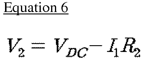
- V 2 V DC ⁇ I 1 R 2
- Equation 8 I 3 + I 2
- Equation 8 may be expressed like Equation 9 below.
- I 3 V DC ⁇ V 2 R 2 + V DC ⁇ V 2 R 2 R 1 ⁇ V 2 R Leak ⁇
- Equation 10 a equation in the first line included in Equation 10 below is derived.
- the equation in the first line is arranged using I 2 and I 3 obtained through Equations 6 to 9, an equation in the last line included in Equation 10 below may be induced.
- the equation in the last line included in Equation 10 is other circuit equations among the simultaneous circuit equations for calculating the isolation resistance R Leak(+) of the cathode terminal and the isolation resistance R Leak(-) of the anode terminal. Therefore, if solutions for the isolation resistance R Leak(+) of the cathode terminal and the isolation resistance R Leak(-) of the anode terminal are obtained by simultaneously using the equation in the last line included in Equation 5 and the equation in the last line included in Equation 10, Equation 11 below may be obtained.
- R Leak + V Bat ⁇ A V Bat ⁇ C ⁇ AC D V Bat ⁇ A + BC
- the control unit 140 may quantitatively calculate the isolation resistance R Leak(+) of the cathode terminal and the isolation resistance R Leak(-) of the anode terminal of the battery 10 by putting the first and second detected isolation voltages V 1 , V 2 received from the voltage detection unit 130 to Equation 11.
- isolation resistance R Leak(+) of the cathode terminal and the isolation resistance R Leak(-) of the anode terminal of the battery 10 are respectively calculated, an electrode of the battery where an isolation breakdown occurs may be accurately figured out.
- Fig. 5 is a circuit diagram schematically showing a diagnosis circuit according to an embodiment of the present disclosure.
- both the first and second isolation resistance measuring units 110, 120 are connected to the cathode terminal and the anode terminal of the battery 10.
- the control unit 140 outputs control signals to both the first and second switches SW1, SW2 to turn on.
- the control unit 140 connects the first and second isolation resistance measuring units 110, 120 to the cathode and anode terminals of the battery 10 at different time points.
- the control unit 140 connects the first and second isolation resistance measuring units 110, 120 to the cathode and anode terminals of the battery 10 at the same time point. Therefore, Fig. 5 shows that the first and second isolation resistance measuring units 110, 120 are simultaneously connected to the cathode and anode terminals of the battery 10 to form a diagnosis circuit.
- the voltage detection unit 130 senses diagnosis voltages applied to the first and second isolation resistance measuring units 110, 120.
- the diagnosis voltage is a voltage applied to the second resistor R 2 , similar to the detected isolation voltage described above.
- the diagnosis voltage is used for diagnosing whether a fault arises at the isolation resistance measuring apparatus 100 according to the present disclosure.
- the voltage applied to the second resistor R 2 included in the first isolation resistance measuring unit 110 is called a first diagnosis voltage V diag1 .
- a voltage applied to the second resistor R 2 included in the second isolation resistance measuring unit 120 is called a second diagnosis voltage V diag2 .
- the voltage detection unit 130 outputs signals corresponding to the first and second diagnosis voltages V diag1 , V diga2 to the control unit 140.
- the control unit 140 determines whether a fault arises at the isolation resistance measuring apparatus by using a circuit equation derived from the diagnosis circuit and the first and second diagnosis voltages V diag1 , V diag2 .
- a circuit equation derived from the diagnosis circuit and the first and second diagnosis voltages V diag1 , V diag2 derived from the diagnosis circuit and the first and second diagnosis voltages V diag1 , V diag2 .
- a current flowing at the first isolation resistance measuring unit 110 is marked as I 1
- a current flowing at the second isolation resistance measuring unit 110 ( ⁇ 120) is marked as I 12
- a voltage between the cathode terminal of the battery and the ground is marked as V Top
- a voltage between the anode terminal of the battery and the ground is marked as V Bottom .
- V diag1 I 1 R 2
- Equation 12 V diag 1 R 2
- V Top V diag 1 + I 1 R 1
- Equation 14 may be expressed like Equation 15 below.
- V Top V diag 1 + V diag 1 R 2 R 1
- V diag2 V DC ⁇ I 2 R 2
- Equation 16 V DC ⁇ V diag 2 R 2
- V Bottom I 2 R 1 ⁇ V diag 2
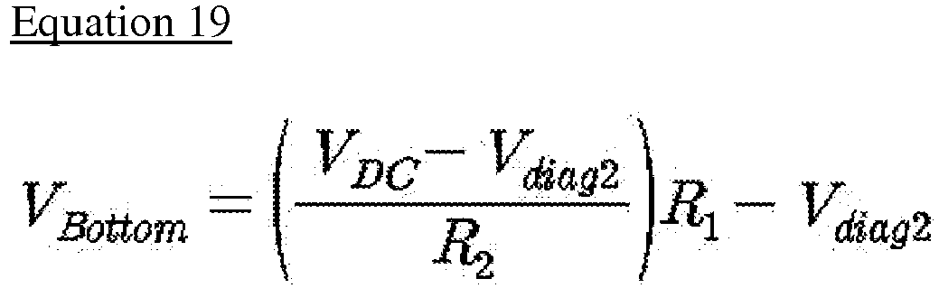
- Equation 18 may be expressed like Equation 19 below.
- V Bottom V DC ⁇ V diag 2 R 2 R 1 ⁇ V diag 2
- Equation 20 The equation in the last line included in Equation 20 is a circuit equation for diagnosing whether a fault arises at the isolation resistance measuring apparatus.
- the voltage value V Bat of the battery, the resistance values of the first and second resistors R 1 , R 2 and the voltage value V DC of the DC power applying unit are already known, and the first and second diagnosis voltages V diag1 , V diag2 may be obtained by means of the voltage detection unit 130.
- the voltage value V Bat of the battery may be a value measured using the voltage detection unit 130. Therefore, in the case the circuit equation is satisfied, if a fault does not arise at the isolation resistance measuring apparatus, the calculated isolation resistance value is reliable.
- the control unit 140 determines whether a fault arises by checking whether a value calculated from Equation 20 falls within an error range preset based on the voltage value V Bat of the battery. Due to errors such as a measurement error which may occur during a process of detecting the first and second diagnosis voltages V diag1 , V diag2 , an error of the voltage value V Bat of the battery, deletion of values other than effective values below the decimal point during a calculating process using the equations, or the like, which may occur when an actual apparatus is implemented, it will be difficult to perfectly satisfy the diagnosis circuit equation.
- an error range is set in advance based on the voltage value V Bat of the battery, and then it will be reliable whether a fault arises at the isolation resistance measuring apparatus if the value calculated from Equation 20 falls within the error range.
- the error range may be set to determine that a fault arises when the value calculated from Equation 20 is different by 1% or more based on the voltage value of the battery.
- control unit 140 may include a switch controller 143, an A/D converter 141 and a central processing unit 142.
- Fig. 6 is a block diagram showing a control unit 140 according to an embodiment of the present disclosure.
- the switch controller 143 outputs switch control signals to control the first and second switches SW1, SW2 to turn on or off.
- the control unit 140 receives a voltage measurement signal from the voltage detection unit 130.
- the A/D converter 141 converts an analog voltage signal output from the voltage detection unit 130 into a digital voltage signal.
- the central processing unit 142 receives the digital voltage signal from the A/D converter 141 and determines whether a fault arises at the isolation resistance measuring apparatus 100.
- the control unit 140 or the central processing unit 142 may include processors known in the art, an application-specific integrated circuit (ASIC), other chipsets, logic circuits, registers, communication modems, data processors or the like in order to execute various control logics described above.
- ASIC application-specific integrated circuit
- the control unit 140 or the central processing unit 142 may be implemented as a group of program modules. At this time, the program modules may be stored in a memory and executed by a processor.
- the isolation resistance measuring apparatus 100 having a fault self-diagnosing function further includes a memory unit 150 which stores the battery voltage value V Bat , the voltage value V DC of the DC power applying unit, the first resistance value R 1 and the second resistance value R 2 .
- the memory unit 150 may be provided in or out of the control unit 140 and connected to the control unit 140 through a device well known in the art.
- the memory unit 150 is a mass storage medium such as a semiconductor device or a hard disk, which are known as being capable of recording or eliminating data, like RAM, ROM, EEPROM or the like, and is a generic term calling devices which store information, regardless of their kinds. Without being limited to a specific memory device.
- the isolation resistance measuring apparatus 100 having a fault self-diagnosing function further includes a transmission unit 160 for forming a communication interface with an external device.
- the control unit 140 may transmit information about whether a fault arises at the isolation resistance measuring apparatus 100 to the external device by means of the transmission unit 160.
- the external device may be a battery analyzing device or a control device of a system on which a battery is loaded.
- the isolation resistance measuring apparatus 100 having a fault self-diagnosing function further includes an alarming unit 170 for outputting a visual or audio alarming signal.
- the control unit 140 may output a visual or audio alarming signal by means of the alarming unit 170.
- the alarming unit 170 may notify the fault occurrence to a user so that the user may take necessary measures.
- the alarming unit 170 may include an LED, an LCD, an alarm, or their combinations. In this case, the alarming unit 170 may notify the fault occurrence by blinking the LED, outputting a warning message at the LCD, or generating an alarm. In addition, the alarming unit 170 may be included in an external device connected to the transmission unit 160. However, the present disclosure is not limited thereto. Moreover, the LED, the LCD and the alarm are just examples of the alarming unit 170, and it is apparent to those skilled in the art that various modified visual or audio alarming devices may be used as the alarming unit 170.
- Fig. 7 is a flowchart for illustrating a fault self-diagnosing method using the isolation resistance measuring apparatus according to an embodiment of the present disclosure.
- Step S400 the battery voltage value V Bat , the voltage value V DC of the DC power applying unit, the first resistance value R 1 and the second resistance value R 2 are stored in the memory unit 150.
- the stored values are put into Equation 20 together with detected isolation voltages and used for diagnosing whether a fault arises at the isolation resistance measuring apparatus.
- the battery voltage value V Bat may be a value measured by using a separate voltage detection circuit (noise).
- Step S410 the control unit 140 outputs control signals to both the first and second switches SW1, SW2 to turn on.
- the first and second isolation resistance measuring units 110, 120 are connected to the cathode and anode terminals of the battery 10 at the same time point. By doing so, a diagnosis circuit is formed.
- Step S420 a signal corresponding to the voltage applied to each second resistor R 2 , namely to the first and second diagnosis voltages V diag1 , V diag2 , is received from the voltage detection unit 130.
- Step S430 the control unit 140 puts the first and second diagnosis voltages V diag1 , V diag2 received in Step S420 to a circuit equation derived from the diagnosis circuit, and compares the value calculated from the equation with the battery voltage value V Bat .
- the process for inducing an equation from the diagnosis circuit and the algorithm for diagnosing whether a fault arises have been described in detail and are not described in detail here.
- Step S440 it is determined whether a fault arises at the isolation resistance measuring apparatus 100.
- Step S440 if a fault arises at the isolation resistance measuring apparatus 100 (YES in Step S440), the process moves to Step S450 to transmit information about the fault occurrence to an external device or moves to Step S460 to give an alarm to a user.
- the present disclosure it is possible to diagnose whether a fault arises at an isolation resistance measuring apparatus of a battery.
- components employed in the isolation resistance measuring apparatus having a fault self-diagnosing function according to the present disclosure as shown in Figs. 1 to 6 should be understood as logically distinguishable components, rather than physically distinguishable components.
Description
- The present disclosure relates to an isolation resistance measuring apparatus having a fault self-diagnosing function and a fault self-diagnosing method using the same, and more particularly, to an apparatus and method for diagnosing a fault of a device which may measure isolation resistance of a battery adopted by a battery power supply system demanding a high voltage.
- Recently, due to the exhaustion of fossil energy and environmental pollution, the interest in electric products, which may operate with electric energy instead of fossil energy, is growing more and more.
- Accordingly, with the increasing development and consumption of mobile devices, electric vehicles, hybrid vehicles, power storage devices, uninterrupted power supplies, or the like, the consumption of secondary batteries as energy sources are rapidly increasing as well as its various forms thereof. Therefore, secondary batteries are being studied very actively to cope with such diverse demands.
- In particular, a device using a high-power large-capacity battery, such as an electric vehicle or a hybrid vehicle, needs to maintain good isolation between the device and the battery. If not, bad isolation of the battery brings a leakage current, which causes various problems. For reference, a leakage current causes unexpected discharge of the battery or malfunctions of electronic components provided at the device. In addition, in case of a device using a high voltage battery, such as an electric vehicle, a leakage current may give a fatal electric shock to a person. Therefore, in order to solve problems caused by such a leakage current, various kinds of isolation resistance measuring devices for determining an isolation state of a secondary battery are being developed and used.
- Meanwhile, if an isolation resistance calculated by an isolation resistance measuring device is not accurate, the advantageous effects of the device deteriorates and is not able to solve various problems caused by a leakage current. In particular, if a problem arises at a voltage detection element included in a device for measuring isolation resistance or a control element for calculating isolation resistance, it is impossible to measure an accurate isolation resistance value, and the measured isolation resistance value is untrustworthy. Therefore, there is a demand for an apparatus and method which may diagnose whether a fault arises at the isolation resistance measuring device
- The document
EP 1 437 600 A1 discloses a circuit and method for ground fault detection. The documentWO 2010 029 353 A1 discloses a device for isolation detection. - The present disclosure is designed to solve the problems of the related art, and therefore the present disclosure is directed to providing an isolation resistance measuring apparatus having a fault self-diagnosing function and a fault self-diagnosing method using the same.
- The present invention is directed to an isolation resistance measuring apparatus according to claim 1 and to a fault self-diagnosis method according to claim 9. Embodiments are described in the dependent claims.
- According to an aspect of the present disclosure, it is possible to diagnose whether a fault arises at an isolation resistance measuring apparatus of a battery.
- According to another aspect of the present disclosure, it is possible to diagnose a fault by using an original configuration, namely without adding any further component to the isolation resistance measuring apparatus of a battery.
- According to another aspect of the present disclosure, it is possible to notify the fault occurrence to a user or an external device, which enables the user to take necessary measures.
- The accompanying drawings illustrate preferred embodiments of the present disclosure and, together with the foregoing disclosure, serve to provide further understanding of the technical spirit of the present disclosure. However, the present disclosure is not to be construed as being limited to the drawings in which:
-
Fig. 1 is a circuit diagram schematically showing an equivalent circuit of an isolation resistance measuring apparatus having a fault self-diagnosing function and a battery power supply system according to an embodiment of the present disclosure; -
Fig. 2 is a circuit diagram schematically showing an equivalent circuit of an isolation resistance measuring apparatus having a fault self-diagnosing function according to an embodiment of the present disclosure; -
Fig. 3 is a circuit diagram schematically showing a first circuit according to an embodiment of the present disclosure; -
Fig. 4 is a circuit diagram schematically showing a second circuit according to an embodiment of the present disclosure; -
Fig. 5 is a circuit diagram schematically showing a diagnosis circuit according to an embodiment of the present disclosure; -
Fig. 6 is a block diagram showing a control unit according to an embodiment of the present disclosure; and -
Fig. 7 is a flowchart for illustrating a fault self-diagnosing method using the isolation resistance measuring apparatus according to an embodiment of the present disclosure. - Hereinafter, preferred embodiments of the present disclosure will be described in detail with reference to the accompanying drawings. Therefore, the description proposed herein is just a preferable example for the purpose of illustrations only, not intended to limit the scope of the invention, which is defined by the appended claims.
-
Fig. 1 is a circuit diagram schematically showing an equivalent circuit of an isolationresistance measuring apparatus 100 having a fault self-diagnosing function and a battery power supply system according to an embodiment of the present disclosure. - As shown in
Fig. 1 , in a battery power supply system including abattery 10 in which a plurality of cells are connected in series or in parallel to form a cell assembly and aload 20 for receiving power output from thebattery 10, the isolationresistance measuring apparatus 100 having a fault self-diagnosing function according to the present disclosure is connected between cathode and anode terminals of thebattery 10. - The
battery 10 is an electric energy storage unit and includes a plurality of rechargeable unit cells to be electrically connected. The unit cell is an electric double layer capacitor including an ultra capacitor or a secondary battery such as a lithium ion battery, a lithium polymer battery, a nickel cadmium battery, a nickel hydrogen battery and a nickel zinc battery. For example, in the case thebattery 10 is a battery used in an electric vehicle or a hybrid vehicle, thebattery 10 outputs high voltage DC power over 200V. However, the present disclosure is not limited to the battery kind, output power, charge capacity or the like. - The
load 20 may be configured with a motor M of an electric vehicle or a hybrid vehicle, a DC to DC converter (noise) or the like. In addition, theload 20 may include a DC/DC cap C1 and Y-caps C2, C3 in order to remove noise generated at the motor M. The DC/DC cap C1 adopts a capacitor with a large capacity to remove high frequency noise generated at the motor M, and the Y-caps C2, C3 remove low frequency noise generated at the motor M. - The isolation
resistance measuring apparatus 100 having a fault self-diagnosing function according to the present disclosure is connected between cathode and anode terminals of thebattery 10 and measures isolation resistance of thebattery 10. Prior to explaining the fault self-diagnosing algorithm of the isolationresistance measuring apparatus 100 having a fault self-diagnosing function according to the present disclosure, an isolation resistance measuring algorithm will be described in brief with reference toFig. 2 . -
Fig. 2 is a circuit diagram schematically showing an equivalent circuit of an isolationresistance measuring apparatus 100 having a fault self-diagnosing function according to an embodiment of the present disclosure. - Referring to
Fig. 2 , the isolationresistance measuring apparatus 100 having a fault self-diagnosing function according to the present disclosure includes a first isolationresistance measuring unit 110, a second isolationresistance measuring unit 120, a first switch SW1, a second switch SW2, avoltage detection unit 130 and acontrol unit 140. - The first switch SW1 selectively connects the first isolation
resistance measuring unit 110 to a cathode terminal of thebattery 10. The first switch SW1 turns on or off according to a control signal of thecontrol unit 140. Therefore, the first isolationresistance measuring unit 110 is selectively connected to the cathode terminal of thebattery 10 according to a control signal of thecontrol unit 140. In this specification, the circuit formed by connecting the first isolationresistance measuring unit 110 to the cathode terminal of thebattery 10 is called a first circuit for better understanding of the present disclosure. When the first circuit is formed, a voltage at the cathode terminal of the battery is applied to the first isolationresistance measuring unit 110. - The second switch SW2 selectively connects the second isolation
resistance measuring unit 120 to an anode terminal of thebattery 10. The second switch SW2 turns on or off according to a control signal of thecontrol unit 140. Therefore, the second isolationresistance measuring unit 120 is selectively connected to the anode terminal of thebattery 10 according to a control signal of thecontrol unit 140. In this specification, the circuit formed by connecting the second isolationresistance measuring unit 120 to the anode terminal of thebattery 10 is called a second circuit for better understanding of the present disclosure. When the second circuit is formed, a voltage at the anode terminal of the battery is applied to the second isolationresistance measuring unit 120. - The second isolation
resistance measuring unit 120 further includes a DC power applying unit DC. Therefore, when the second circuit is formed, a positive voltage may be applied to the second isolationresistance measuring unit 120, which ensures a voltage value other than 0 to be sensed by thevoltage detection unit 130. - Preferably, the first and second isolation
resistance measuring units battery 10 may be set by arbitrarily selecting a resistance value of each of the plurality of resistor elements. A range of voltage sensed by thevoltage detection unit 130 may be set to be 5V or below by suitably selecting a resistance value of the resistor element, as an example. -
Fig. 2 shows an example in which the first and second isolationresistance measuring units Fig. 2 shows that first and second isolationresistance measuring units - In addition, even though the first isolation
resistance measuring unit 110 and the second isolationresistance measuring unit 120 are depicted as including only resistor elements, it should be understood that an existing electric component capable of receiving a voltage applied from thebattery 10 and measuring a voltage may be added in addition to the resistor element or substituted for the resistor element. - The
voltage detection unit 130 senses a detected isolation voltage applied to the first and second isolationresistance measuring units battery 10. In this specification, when the first circuit is formed, a voltage applied to the second resistor R2 included in the first isolationresistance measuring unit 110 is called a first detected isolation voltage V1. In addition, when the second circuit is formed, a voltage applied to the second resistor R2 included in the second isolationresistance measuring unit 120 is called a second detected isolation voltage V2. Thevoltage detection unit 130 outputs signals corresponding to the first and second detected isolation voltages V1, V2 to thecontrol unit 140. - The
control unit 140 outputs a control signal to the first and second switches SW1, SW2 to turn on or off. When sending a control signal to the first switch SW1 to turn on, thecontrol unit 140 controls the second switch SW2 to maintain a turn-off state. On the contrary, when sending a control signal to the second switch SW2 to turn on, thecontrol unit 140 controls the first switch SW1 to maintain a turn-off state. By doing so, thecontrol unit 140 allows the first and second isolationresistance measuring units battery 10 at different time points. Meanwhile, the first and second switches SW1, SW2 are named to be distinguishable from each other and do not represent an order in which thecontrol unit 140 outputs control signals or an order in which the isolationresistance measuring apparatus 100 operates. - The
control unit 140 receives signals corresponding to first and second detected isolation voltages V1, V2 received from thevoltage detection unit 130. In this case, thecontrol unit 140 calculates an isolation resistance RLeak(+) of the cathode terminal and an isolation resistance RLeak(-) of the anode terminal from simultaneous circuit equations derived from the first and second detected isolation voltages V1, V2 and the first and second circuits. A calculating algorithm for the isolation resistance value using the simultaneous circuit equations will be described later in detail. - Meanwhile, the voltage of the
battery 10 is expressed as VBat, and the isolation resistance RLeak(+) of the cathode terminal and the isolation resistance RLeak(-) of the anode terminal respectively displayed at the cathode and anode terminals of thebattery 10 express virtual resistance values which represent an isolation state of thebattery 10. Therefore, if the isolation state of thebattery 10 is destroyed, the isolation resistance RLeak(+) of the cathode terminal and the isolation resistance RLeak(-) of the anode terminal are measured as low values, which can be interpreted that a leakage current has occurred. - Hereinafter, an algorithm to calculate the isolation resistance RLeak(+) of the cathode terminal and the isolation resistance RLeak(-) of the anode terminal of the isolation
resistance measuring apparatus 100 having a fault self-diagnosing function according to the present disclosure will be described in detail with reference toFigs. 3 and 4 . -
Fig. 3 is a circuit diagram schematically showing the first circuit according to an embodiment of the present disclosure. - Referring to
Fig. 3 , a current flowing at the first isolationresistance measuring unit 110 is marked as I1, a current flowing at the isolation resistance RLeak(+) of the cathode terminal is marked as I2, and a current flowing at the isolation resistance RLeak(-) of the anode terminal is marked as I3. - First, a value of the first detected isolation voltage V1 may be expressed with I1 as in Equation 1 below.

- In addition, since the first isolation
resistance measuring unit 110 is in parallel with the isolation resistance RLeak(+) of the cathode terminal, a relationship likeEquation 2 below is established.
- Meanwhile, if Kirchhoff's current law is applied based on a node n connected to the ground, Equation 3 below is derived.

- If
Equations 1 and 2 are put into Equation 3 and then arranged with respect to I3, Equation 3 may be expressed like Equation 4 below.
- Meanwhile, if Kirchhoff's voltage low is applied based on Mesh 1 shown in
Fig. 3 , an equation in the first line included in Equation 5 below is derived. In addition, if the equation in the first line is arranged using I2 and I3 obtained through Equations 1 to 4, an equation in the last line included in Equation 5 below may be induced.
- The equation in the last line included in Equation 5 is one of simultaneous circuit equations for calculating the isolation resistance RLeak(+) of the cathode terminal and the isolation resistance RLeak(-) of the anode terminal and is used together with other circuit equations described below.
-
Fig. 4 is a circuit diagram schematically showing the second circuit according to an embodiment of the present disclosure. - Referring to
Fig. 4 , a current flowing at the second isolationresistance measuring unit 120 is marked as I1, a current flowing at the isolation resistance RLeak(-) of the anode terminal is marked as I2, and a current flowing at the isolation resistance RLeak(+) of the cathode terminal is marked as I3. - First, a value of the second detected isolation voltage V2 is expressed with I1 as in Equation 6 below.
- In addition, since the second isolation
resistance measuring unit 120 is in parallel with the isolation resistance RLeak(-) of the anode terminal, a relationship as in Equation 7 below is established.
- Meanwhile, if Kirchhoff's current law is applied based on a node n connected to the ground, Equation 8 below is derived.

- If Equations 6 and 7 are put into Equation 8 and then arranged with respect to I3, Equation 8 may be expressed like Equation 9 below.

- Meanwhile, if Kirchhoff's voltage low is applied based on
Mesh 2 shown inFig. 4 , an equation in the first line included inEquation 10 below is derived. In addition, if the equation in the first line is arranged using I2 and I3 obtained through Equations 6 to 9, an equation in the last line included inEquation 10 below may be induced.
- The equation in the last line included in
Equation 10 is other circuit equations among the simultaneous circuit equations for calculating the isolation resistance RLeak(+) of the cathode terminal and the isolation resistance RLeak(-) of the anode terminal. Therefore, if solutions for the isolation resistance RLeak(+) of the cathode terminal and the isolation resistance RLeak(-) of the anode terminal are obtained by simultaneously using the equation in the last line included in Equation 5 and the equation in the last line included inEquation 10, Equation 11 below may be obtained.
- In Equation 11, the voltage value VBat of the battery, the resistance values of the first and second resistors R1, R2 and the voltage value VDC of the DC power applying unit are already known, and the first and second detected isolation voltages V1, V2 may be obtained by means of the
voltage detection unit 130. Therefore, thecontrol unit 140 may quantitatively calculate the isolation resistance RLeak(+) of the cathode terminal and the isolation resistance RLeak(-) of the anode terminal of thebattery 10 by putting the first and second detected isolation voltages V1, V2 received from thevoltage detection unit 130 to Equation 11. - If the isolation resistance RLeak(+) of the cathode terminal and the isolation resistance RLeak(-) of the anode terminal of the
battery 10 are respectively calculated, an electrode of the battery where an isolation breakdown occurs may be accurately figured out. - Heretofore, an algorithm for the isolation
resistance measuring apparatus 100 having a fault self-diagnosing function according to the present disclosure to calculate an isolation resistance value has been described in brief. Hereinafter, a fault self-diagnosing algorithm of the isolationresistance measuring apparatus 100 having a fault self-diagnosing function according to the present disclosure will be described. -
Fig. 5 is a circuit diagram schematically showing a diagnosis circuit according to an embodiment of the present disclosure. - Referring to
Fig. 5 , it may be found that both the first and second isolationresistance measuring units battery 10. - The
control unit 140 outputs control signals to both the first and second switches SW1, SW2 to turn on. When measuring isolation resistance, thecontrol unit 140 connects the first and second isolationresistance measuring units battery 10 at different time points. However, when diagnosing whether a fault arises, thecontrol unit 140 connects the first and second isolationresistance measuring units battery 10 at the same time point. Therefore,Fig. 5 shows that the first and second isolationresistance measuring units battery 10 to form a diagnosis circuit. - The
voltage detection unit 130 senses diagnosis voltages applied to the first and second isolationresistance measuring units resistance measuring apparatus 100 according to the present disclosure. In this specification, the voltage applied to the second resistor R2 included in the first isolationresistance measuring unit 110 is called a first diagnosis voltage Vdiag1. In addition, a voltage applied to the second resistor R2 included in the second isolationresistance measuring unit 120 is called a second diagnosis voltage Vdiag2. Thevoltage detection unit 130 outputs signals corresponding to the first and second diagnosis voltages Vdiag1, Vdiga2 to thecontrol unit 140. - The
control unit 140 determines whether a fault arises at the isolation resistance measuring apparatus by using a circuit equation derived from the diagnosis circuit and the first and second diagnosis voltages Vdiag1, Vdiag2. Hereinafter, an algorithm for diagnosing whether a fault arises at the isolation resistance measuring apparatus according to the present disclosure will be described in detail with reference to following equations andFig. 5 . - Referring to
Fig. 5 , a current flowing at the first isolationresistance measuring unit 110 is marked as I1, and a current flowing at the second isolation resistance measuring unit 110 (→ 120) is marked as I12. In addition, a voltage between the cathode terminal of the battery and the ground is marked as VTop, and a voltage between the anode terminal of the battery and the ground is marked as VBottom. - First, a value of the first diagnosis voltage Vdiag1 may be expressed with I1 as in Equation 12 below.

- If Equation 12 is arranged with respect to I1, Equation 13 below may be expressed.

- In addition, since the voltage VTop between the cathode terminal of the battery and the ground is a voltage applied to the first isolation
resistance measuring unit 110, a relationship like Equation 14 below is established.
- If I1 arranged in Equation 13 is put into Equation 14, Equation 14 may be expressed like Equation 15 below.

- Meanwhile, a value of the second diagnosis voltage Vdiag2 may be expressed with I2 as in Equation 16 below.

- If Equation 16 is arranged with respect to I2, Equation 17 below may be expressed.

- In addition, since the voltage VBottom between the ground and the anode terminal of the battery is a voltage applied to the second isolation
resistance measuring unit 120, a relationship like Equation 18 below is established.
- If I2 arranged in Equation 17 is put into Equation 18, Equation 18 may be expressed like Equation 19 below.
- Finally, since the voltage VBat of the battery is expressed as the sum of VTop and VBottom, an equation in the first line included in
Equation 20 below is derived. In addition, if the equation in the first line is arranged using VTop and VBottom obtained through Equations 15 and 19, an equation in the last line included inEquation 20 below may be induced.
- The equation in the last line included in
Equation 20 is a circuit equation for diagnosing whether a fault arises at the isolation resistance measuring apparatus. InEquation 20, the voltage value VBat of the battery, the resistance values of the first and second resistors R1, R2 and the voltage value VDC of the DC power applying unit are already known, and the first and second diagnosis voltages Vdiag1, Vdiag2 may be obtained by means of thevoltage detection unit 130. Here, the voltage value VBat of the battery may be a value measured using thevoltage detection unit 130. Therefore, in the case the circuit equation is satisfied, if a fault does not arise at the isolation resistance measuring apparatus, the calculated isolation resistance value is reliable. - According to another embodiment of the present disclosure, the
control unit 140 determines whether a fault arises by checking whether a value calculated fromEquation 20 falls within an error range preset based on the voltage value VBat of the battery. Due to errors such as a measurement error which may occur during a process of detecting the first and second diagnosis voltages Vdiag1, Vdiag2, an error of the voltage value VBat of the battery, deletion of values other than effective values below the decimal point during a calculating process using the equations, or the like, which may occur when an actual apparatus is implemented, it will be difficult to perfectly satisfy the diagnosis circuit equation. Therefore, by considering such potential errors, an error range is set in advance based on the voltage value VBat of the battery, and then it will be reliable whether a fault arises at the isolation resistance measuring apparatus if the value calculated fromEquation 20 falls within the error range. Preferably, the error range may be set to determine that a fault arises when the value calculated fromEquation 20 is different by 1% or more based on the voltage value of the battery. - In order to execute the diagnosing algorithm described above, the
control unit 140 may include aswitch controller 143, an A/D converter 141 and acentral processing unit 142. -
Fig. 6 is a block diagram showing acontrol unit 140 according to an embodiment of the present disclosure. - Referring to
Fig. 6 , theswitch controller 143 outputs switch control signals to control the first and second switches SW1, SW2 to turn on or off. In addition, thecontrol unit 140 receives a voltage measurement signal from thevoltage detection unit 130. At this time, the A/D converter 141 converts an analog voltage signal output from thevoltage detection unit 130 into a digital voltage signal. In addition, thecentral processing unit 142 receives the digital voltage signal from the A/D converter 141 and determines whether a fault arises at the isolationresistance measuring apparatus 100. - The
control unit 140 or thecentral processing unit 142 may include processors known in the art, an application-specific integrated circuit (ASIC), other chipsets, logic circuits, registers, communication modems, data processors or the like in order to execute various control logics described above. In addition, when the control logics described above are implemented with software, thecontrol unit 140 or thecentral processing unit 142 may be implemented as a group of program modules. At this time, the program modules may be stored in a memory and executed by a processor. - Preferably, the isolation
resistance measuring apparatus 100 having a fault self-diagnosing function according to the present disclosure further includes amemory unit 150 which stores the battery voltage value VBat, the voltage value VDC of the DC power applying unit, the first resistance value R1 and the second resistance value R2. Thememory unit 150 may be provided in or out of thecontrol unit 140 and connected to thecontrol unit 140 through a device well known in the art. Thememory unit 150 is a mass storage medium such as a semiconductor device or a hard disk, which are known as being capable of recording or eliminating data, like RAM, ROM, EEPROM or the like, and is a generic term calling devices which store information, regardless of their kinds. Without being limited to a specific memory device. - According to another aspect of the present disclosure, the isolation
resistance measuring apparatus 100 having a fault self-diagnosing function according to the present disclosure further includes atransmission unit 160 for forming a communication interface with an external device. In this case, thecontrol unit 140 may transmit information about whether a fault arises at the isolationresistance measuring apparatus 100 to the external device by means of thetransmission unit 160. The external device may be a battery analyzing device or a control device of a system on which a battery is loaded. - According to another aspect of the present disclosure, the isolation
resistance measuring apparatus 100 having a fault self-diagnosing function according to the present disclosure further includes analarming unit 170 for outputting a visual or audio alarming signal. In this case, if a fault arises at the isolationresistance measuring apparatus 100, thecontrol unit 140 may output a visual or audio alarming signal by means of thealarming unit 170. When a fault arises, thealarming unit 170 may notify the fault occurrence to a user so that the user may take necessary measures. - For example, the
alarming unit 170 may include an LED, an LCD, an alarm, or their combinations. In this case, thealarming unit 170 may notify the fault occurrence by blinking the LED, outputting a warning message at the LCD, or generating an alarm. In addition, thealarming unit 170 may be included in an external device connected to thetransmission unit 160. However, the present disclosure is not limited thereto. Moreover, the LED, the LCD and the alarm are just examples of thealarming unit 170, and it is apparent to those skilled in the art that various modified visual or audio alarming devices may be used as thealarming unit 170. - Hereinafter, a fault self-diagnosing method of the isolation resistance measuring apparatus, which corresponds to an operating mechanism of the apparatus, will be described. However, the configuration of the isolation
resistance measuring apparatus 100 having a fault self-diagnosing function is not described again here. -
Fig. 7 is a flowchart for illustrating a fault self-diagnosing method using the isolation resistance measuring apparatus according to an embodiment of the present disclosure. - First, in Step S400, the battery voltage value VBat, the voltage value VDC of the DC power applying unit, the first resistance value R1 and the second resistance value R2 are stored in the
memory unit 150. The stored values are put intoEquation 20 together with detected isolation voltages and used for diagnosing whether a fault arises at the isolation resistance measuring apparatus. Here, the battery voltage value VBat may be a value measured by using a separate voltage detection circuit (noise). - Next, in Step S410, the
control unit 140 outputs control signals to both the first and second switches SW1, SW2 to turn on. In this step, the first and second isolationresistance measuring units battery 10 at the same time point. By doing so, a diagnosis circuit is formed. - Next, in Step S420, a signal corresponding to the voltage applied to each second resistor R2, namely to the first and second diagnosis voltages Vdiag1, Vdiag2, is received from the
voltage detection unit 130. - Next, in Step S430, the
control unit 140 puts the first and second diagnosis voltages Vdiag1, Vdiag2 received in Step S420 to a circuit equation derived from the diagnosis circuit, and compares the value calculated from the equation with the battery voltage value VBat. The process for inducing an equation from the diagnosis circuit and the algorithm for diagnosing whether a fault arises have been described in detail and are not described in detail here. In addition, in Step S440, it is determined whether a fault arises at the isolationresistance measuring apparatus 100. - Preferably, if a fault arises at the isolation resistance measuring apparatus 100 (YES in Step S440), the process moves to Step S450 to transmit information about the fault occurrence to an external device or moves to Step S460 to give an alarm to a user.
- According to the present disclosure, it is possible to diagnose whether a fault arises at an isolation resistance measuring apparatus of a battery. In addition, it is possible to diagnose a fault by using an original configuration, namely without adding any further component to the isolation resistance measuring apparatus of a battery. Moreover, it is possible to notify the fault occurrence to a user or an external device, which enables the user to take necessary measures.
- Meanwhile, in the present disclosure, components employed in the isolation resistance measuring apparatus having a fault self-diagnosing function according to the present disclosure as shown in
Figs. 1 to 6 should be understood as logically distinguishable components, rather than physically distinguishable components. - The present disclosure has been described in detail. However, it should be understood that the detailed description and specific examples, while indicating preferred embodiments of the disclosure, are given by way of illustration only, since various changes and modifications within the scope of the disclosure will become apparent to those skilled in the art from this detailed description The scope of the invention is defined by the appended claims.
Claims (14)
- An isolation resistance measuring apparatus (100) having a fault self-diagnosing function, the apparatus comprising:a first isolation resistance measuring unit (110) and a second isolation resistance measuring unit (120) respectively connected to a cathode terminal and an anode terminal of a battery;a first switch (SW1) and a second switch (SW2) configured to connect the first isolation resistance measuring unit (110) and the second isolation resistance measuring unit (120) to the cathode terminal and the anode terminal, respectively, for measuring respectively a first and second detected isolation voltages (V1, V2);a voltage detection unit (130) configured to sense first and second voltages applied to the first and second isolation resistance measuring units (110, 120) respectively; anda control unit (140) configured to:turn on the first switch (SW1) and control the second switch (SW2) to maintain a turn-off state to form a first circuit,turn on the second switch (SW2) and control the first switch (SW1) to maintain a turn-off state to form a second circuit,receive signals corresponding to the first and second detected isolation voltage (V1, V2),calculate an isolation resistance of the cathode terminal and an isolation resistance of the anode terminal by obtaining a solution of simultaneous circuit equations composed of a circuit equation derived from the first circuit and a circuit equation derived from the second circuit by using the first and second detected isolation voltages (V1, V2) andoutput control signals respectively to the first and second switches (SW1, SW2) to turn on the first and second switches (SW1, SW2) to form a diagnosis circuit, the control unit (140) configured to determine whether a fault arises at the isolation resistance measuring apparatus (100) by using a circuit equation derived from the diagnosis circuit and the first and second diagnosis voltages respectively corresponding to the first and second voltages received from the voltage detection unit (130)when the diagnosis circuit is formed;wherein the second isolation resistance measuring unit further includes a DC power applying unit,characterised in that:each of the first isolation resistance measuring unit (110) and the second isolation resistance measuring unit (120) includes a first resistor (R1) having a first resistance and a second resistor (R2) having a second resistance, the first resistor (R1) and the second resistor (R2) being connected to each other in series,the voltage detection unit (130) is configured to sense a voltage applied to the second resistor (R2) of the first isolation resistance measuring unit (110) and a voltage applied to the second resistor (R2) of the second isolation resistance measuring unit (120),the control unit (140) is configured to determine whether a fault arises at the isolation resistance measuring apparatus, by comparing the solution of simultaneous circuit equations with the battery voltage value andthe control unit (140) is configured to determine whether a fault arises at the isolation resistance measuring apparatus, by checking whether the following equation is valid when the first and second diagnosis voltages are put therein:

- The isolation resistance measuring apparatus having a fault self-diagnosing function according to claim 1,
wherein the control unit (140) is configured to determine whether a fault arises, by checking whether a value calculated from the equation falls within an error range preset based on the voltage value of the battery. - The isolation resistance measuring apparatus having a fault self-diagnosing function according to claim 2,
wherein the control unit (140) is configured to determine that a fault arises when the value calculated from the equation is different by 1% or more based on the voltage value of the battery. - The isolation resistance measuring apparatus having a fault self-diagnosing function according to claim 1, further comprising a memory unit (150) which is configured to store a battery voltage value (VBat), a voltage value of the DC power applying unit, a first resistance value (R1) and a second resistance value (R2).
- The isolation resistance measuring apparatus having a fault self-diagnosing function according to claim 1, wherein the control unit (140) includes:a switch controller (143) configured to control the first and second switches to turn on or off;an A/D converter (141) configured to convert an analog voltage signal output from the voltage detection unit into a digital voltage signal; anda central processing unit (142) configured to receive the digital voltage signal from the A/D converter and determine whether a fault arises at the isolation resistance measuring apparatus.
- The isolation resistance measuring apparatus having a fault self-diagnosing function according to claim 1, further comprising a transmission unit (160) configured to form a communication interface with an external device,
wherein the control unit (140) is configured to transmit information about whether a fault arises at the isolation resistance measuring apparatus to the external device by means of the transmission unit. - The isolation resistance measuring apparatus having a fault self-diagnosing function according to claim 6,
wherein the external device is a battery analyzing device or a control device of a system on which a battery is loaded. - The isolation resistance measuring apparatus having a fault self-diagnosing function according to claim 1, further comprising an alarming unit (170) configured to output a visual or audio alarming signal,
wherein the control unit (140) is configured to output a visual or audio alarming signal by means of the alarming unit when it is determined that a fault arises at the isolation resistance measuring apparatus. - A fault self-diagnosing method for an isolation resistance measuring apparatus as claimed in claims 1 to 8, the method comprising:(a) outputting control signals respectively to the first switch (SW1) and second switch (SW2) to turn on the first and second switches to form a diagnosis circuit;(b) receiving first and second diagnosis voltages (Vdiag1, Vdiag2) respectively corresponding to the first and second voltages detected by the first and second isolation resistance measuring units (110, 120); and(c) determining whether a fault arises at the isolation resistance measuring apparatus by using a circuit equation derived from the diagnosis circuit and the first and second diagnosis voltages;wherein the step (c) determines whether a fault arises at the isolation resistance measuring apparatus, by comparing the solution of simultaneous circuit equations with the battery voltage value andwherein the step (c) determines whether a fault arises at the isolation resistance measuring apparatus, by checking whether the following equation is valid when the first and second diagnosis voltages are put therein:

- The fault self-diagnosing method of an isolation resistance measuring apparatus according to claim 9,
wherein the step (c) determines whether a fault arises, by checking whether a value calculated from the equation falls within an error range preset based on the voltage value of the battery. - The fault self-diagnosing method of an isolation resistance measuring apparatus according to claim 10,
wherein the step (c) determines that a fault arises when the value calculated from the equation is different by 1% or more based on the voltage value of the battery. - The fault self-diagnosing method of an isolation resistance measuring apparatus according to claim 9, further comprising:
storing a battery voltage value (Vbat), a voltage value of the DC power applying unit, a first resistance value (R1) and a second resistance value (R2). - The fault self-diagnosing method of an isolation resistance measuring apparatus according to claim 9, further comprising:
transmitting information about whether a fault arises at the isolation resistance measuring apparatus to an external device. - The fault self-diagnosing method of an isolation resistance measuring apparatus according to claim 9, further comprising:
outputting a visual or audio alarming signal to a user when it is determined in the step (c) that a fault arises at the isolation resistance measuring apparatus.
Priority Applications (1)
| Application Number | Priority Date | Filing Date | Title |
|---|---|---|---|
| PL13772234T PL2720056T3 (en) | 2012-04-04 | 2013-04-04 | Isolation resistance measuring apparatus having fault self-diagnosing function and self-diagnosing method using the same |
Applications Claiming Priority (2)
| Application Number | Priority Date | Filing Date | Title |
|---|---|---|---|
| KR20120034907 | 2012-04-04 | ||
| PCT/KR2013/002817 WO2013151355A1 (en) | 2012-04-04 | 2013-04-04 | Insulation resistance measurement device having failure self-diagnosis function, and self-diagnosis method using same |
Publications (3)
| Publication Number | Publication Date |
|---|---|
| EP2720056A1 EP2720056A1 (en) | 2014-04-16 |
| EP2720056A4 EP2720056A4 (en) | 2015-10-21 |
| EP2720056B1 true EP2720056B1 (en) | 2021-03-17 |
Family
ID=49633645
Family Applications (1)
| Application Number | Title | Priority Date | Filing Date |
|---|---|---|---|
| EP13772234.4A Active EP2720056B1 (en) | 2012-04-04 | 2013-04-04 | Isolation resistance measuring apparatus having fault self-diagnosing function and self-diagnosing method using the same |
Country Status (7)
| Country | Link |
|---|---|
| US (1) | US8952701B2 (en) |
| EP (1) | EP2720056B1 (en) |
| JP (1) | JP5745694B2 (en) |
| KR (1) | KR101453786B1 (en) |
| CN (1) | CN103688183B (en) |
| PL (1) | PL2720056T3 (en) |
| WO (1) | WO2013151355A1 (en) |
Families Citing this family (36)
| Publication number | Priority date | Publication date | Assignee | Title |
|---|---|---|---|---|
| WO2013147493A1 (en) * | 2012-03-27 | 2013-10-03 | 주식회사 엘지화학 | Insulation resistance measurement device having malfuction self-diagnosis function, and method for self-diagnosing malfuction using same |
| US9720049B2 (en) | 2014-07-22 | 2017-08-01 | Robert Bosch Battery Systems Llc | System and method for high voltage system isolation resistance measurement |
| DE102014220017A1 (en) | 2014-10-02 | 2016-04-07 | Robert Bosch Gmbh | Battery system with a trained for supplying a high-voltage network with electrical energy battery and a measuring device for measuring at least one insulation resistance of the battery |
| KR101771226B1 (en) | 2014-10-02 | 2017-09-05 | 주식회사 엘지화학 | Isolation resistance measurement apparatus that can rapidly measure isolation resistance |
| CN104677407B (en) * | 2015-02-14 | 2017-03-29 | 徐勤朗 | A kind of detection method of the failure detector circuit for being applied to photo-electronic directly reading register |
| DE102015208411A1 (en) * | 2015-05-06 | 2016-11-10 | Robert Bosch Gmbh | Electronic module and method and apparatus for testing an electronic module |
| KR101936220B1 (en) * | 2015-11-16 | 2019-01-08 | 주식회사 엘지화학 | System and apparatus for measuring of insulation resistance |
| DE102016207197B3 (en) * | 2016-04-27 | 2017-07-13 | Bender Gmbh & Co. Kg | Method and devices for functional testing of an insulation monitoring device |
| US10161981B2 (en) * | 2016-09-14 | 2018-12-25 | Johnson Controls Technology Company | Isolation barrier fault detection circuit |
| KR101991910B1 (en) * | 2016-11-16 | 2019-06-21 | 주식회사 엘지화학 | Apparatus and method for measuring isolation resistance of battery |
| TWM569100U (en) | 2017-01-09 | 2018-10-21 | 美商米沃奇電子工具公司 | Battery pack |
| KR102069942B1 (en) * | 2017-01-24 | 2020-01-23 | 주식회사 엘지화학 | Measuring apparatus and method of insulation resistance of the battery pack using the negative relay |
| EP3361271B1 (en) * | 2017-02-08 | 2022-06-01 | Fico Triad, S.A. | Device and method for measuring isolation resistance of battery powered systems |
| CN106680579A (en) * | 2017-02-22 | 2017-05-17 | 浙江零跑科技有限公司 | Circuit module of integrated multi-function detection and sampling method |
| DE102017108207A1 (en) * | 2017-04-18 | 2018-10-18 | Knorr-Bremse Systeme für Nutzfahrzeuge GmbH | Device for power supply for a control device and method for monitoring a power supply |
| CN107728066A (en) | 2017-08-29 | 2018-02-23 | 宁德时代新能源科技股份有限公司 | Insulation detection circuit and method and battery management system |
| KR102256099B1 (en) * | 2017-11-29 | 2021-05-25 | 주식회사 엘지에너지솔루션 | Battery back |
| KR102270232B1 (en) | 2017-12-11 | 2021-06-25 | 주식회사 엘지에너지솔루션 | Method and apparatus for diagnosing fault of positive contactor of battery pack |
| KR102270233B1 (en) * | 2017-12-12 | 2021-06-25 | 주식회사 엘지에너지솔루션 | Method and apparatus for diagnosing fault of negative contactor of battery pack |
| KR102259382B1 (en) | 2017-12-15 | 2021-06-01 | 주식회사 엘지에너지솔루션 | Method and apparatus for detecting a battery leakage |
| CN108333548A (en) * | 2017-12-30 | 2018-07-27 | 宁德时代新能源科技股份有限公司 | Insulation resistance measuring apparatus and fault self-diagnosis method |
| CN110726907A (en) | 2018-07-17 | 2020-01-24 | 宁德时代新能源科技股份有限公司 | Insulation detection device and method for energy storage system |
| KR102256096B1 (en) | 2018-08-27 | 2021-05-27 | 주식회사 엘지에너지솔루션 | Apparatus and method for diagnosing insulation state between battery pack and ground, and the battery pack including the apparatus |
| CN109061307A (en) * | 2018-09-06 | 2018-12-21 | 北京长城华冠汽车科技股份有限公司 | The method for diagnosing faults of insulating resistor detecting circuit |
| CN109765495B (en) * | 2019-01-15 | 2020-11-10 | 宁德时代新能源科技股份有限公司 | Insulation detection circuit, insulation detection method and battery management system |
| CN110967606A (en) * | 2019-01-15 | 2020-04-07 | 宁德时代新能源科技股份有限公司 | Insulation detection circuit, insulation detection method and battery management system |
| KR20210029598A (en) * | 2019-09-06 | 2021-03-16 | 주식회사 엘지화학 | Apparatus and method for diagnosing isolation resistance measurement circuit |
| CN112526424B (en) | 2019-09-18 | 2021-09-28 | 宁德时代新能源科技股份有限公司 | Detection method of insulation detection circuit and battery management system |
| JP7248220B2 (en) * | 2019-11-13 | 2023-03-29 | エルジー エナジー ソリューション リミテッド | Device and method for diagnosing failure of switch unit included in multi-battery pack |
| CN111697689B (en) * | 2020-05-13 | 2021-09-24 | 北京四方继保工程技术有限公司 | Power supply equipment hidden fault monitoring method and system |
| CN114002502B (en) * | 2020-07-27 | 2023-01-13 | 宁德时代新能源科技股份有限公司 | Insulation resistance detection circuit and method |
| CN112327681A (en) * | 2020-10-14 | 2021-02-05 | 北京三快在线科技有限公司 | Power supply control device, fault positioning method, device, medium, and unmanned device |
| KR102463637B1 (en) * | 2020-11-03 | 2022-11-09 | 한국전기안전공사 | Online insulation resistance application and method of DC system |
| US11714111B2 (en) | 2021-02-12 | 2023-08-01 | Samsung Sdi Co., Ltd. | Isolation measurement monitoring for ASIL applications |
| HUE063379T2 (en) * | 2021-02-12 | 2024-01-28 | Samsung Sdi Co Ltd | Isolation measurement monitoring for asil applications |
| KR20230069593A (en) * | 2021-11-12 | 2023-05-19 | 주식회사 엘지에너지솔루션 | Apparatus for measuring insulation resistance |
Family Cites Families (14)
| Publication number | Priority date | Publication date | Assignee | Title |
|---|---|---|---|---|
| JP3957598B2 (en) * | 2002-09-10 | 2007-08-15 | 松下電器産業株式会社 | Insulation resistance detection method and apparatus |
| DE10300539B4 (en) * | 2003-01-09 | 2007-05-24 | Daimlerchrysler Ag | Circuit and method for detecting insulation faults |
| JP4198019B2 (en) * | 2003-10-07 | 2008-12-17 | 矢崎総業株式会社 | State detection method and insulation resistance drop detector |
| JP4280145B2 (en) * | 2003-10-23 | 2009-06-17 | 矢崎総業株式会社 | Insulation resistance drop detector and self-diagnosis method thereof |
| JPWO2007026603A1 (en) * | 2005-08-29 | 2009-03-26 | トヨタ自動車株式会社 | Insulation resistance drop detector and self-abnormality diagnosis method for insulation resistance drop detector |
| JP4682037B2 (en) * | 2005-12-22 | 2011-05-11 | 矢崎総業株式会社 | Insulation detector |
| WO2008016179A1 (en) * | 2006-08-04 | 2008-02-07 | Toyota Jidosha Kabushiki Kaisha | Insulation resistance determining system, insulation resistance determining apparatus and insulation resistance determining method |
| KR101291724B1 (en) * | 2007-09-04 | 2013-07-31 | 주식회사 엘지화학 | Apparatus and Method for sensing leakage current of battery |
| GB0816452D0 (en) * | 2008-09-09 | 2008-10-15 | Ricardo Uk Ltd | Isolation detection |
| JP5234282B2 (en) * | 2009-02-09 | 2013-07-10 | 三菱自動車工業株式会社 | Battery pack inspection device |
| KR20100104139A (en) * | 2009-03-16 | 2010-09-29 | 주식회사 크라또 | On-line insulation resistance measurement system and apparatus |
| EP2256506B1 (en) * | 2009-05-27 | 2019-07-03 | Bender GmbH & Co. KG | Method and device for insulation monitoring of unearthed direct voltage and alternating current networks |
| CN102341714B (en) * | 2009-12-15 | 2016-01-20 | 株式会社Pues | Insulation-degradation detecting device |
| KR101354583B1 (en) * | 2010-09-17 | 2014-01-22 | 에스케이이노베이션 주식회사 | Insulation resistance measurement circuit |
-
2013
- 2013-04-04 CN CN201380002318.7A patent/CN103688183B/en active Active
- 2013-04-04 EP EP13772234.4A patent/EP2720056B1/en active Active
- 2013-04-04 PL PL13772234T patent/PL2720056T3/en unknown
- 2013-04-04 JP JP2014516931A patent/JP5745694B2/en active Active
- 2013-04-04 KR KR1020130036809A patent/KR101453786B1/en active IP Right Grant
- 2013-04-04 WO PCT/KR2013/002817 patent/WO2013151355A1/en active Application Filing
- 2013-11-26 US US14/090,719 patent/US8952701B2/en active Active
Non-Patent Citations (1)
| Title |
|---|
| None * |
Also Published As
| Publication number | Publication date |
|---|---|
| KR101453786B1 (en) | 2014-11-03 |
| PL2720056T3 (en) | 2021-07-12 |
| JP2014522966A (en) | 2014-09-08 |
| CN103688183B (en) | 2016-04-20 |
| EP2720056A1 (en) | 2014-04-16 |
| JP5745694B2 (en) | 2015-07-08 |
| CN103688183A (en) | 2014-03-26 |
| US20140084933A1 (en) | 2014-03-27 |
| EP2720056A4 (en) | 2015-10-21 |
| KR20130112802A (en) | 2013-10-14 |
| US8952701B2 (en) | 2015-02-10 |
| WO2013151355A1 (en) | 2013-10-10 |
Similar Documents
| Publication | Publication Date | Title |
|---|---|---|
| EP2720056B1 (en) | Isolation resistance measuring apparatus having fault self-diagnosing function and self-diagnosing method using the same | |
| EP2796887B1 (en) | Isolation resistance measurement apparatus having fault self-diagnosis function and fault self-diagnosing method using the same | |
| EP2801837B1 (en) | Device and method for measuring insulation resistance of battery | |
| KR101504274B1 (en) | Apparatus and method for diagnosis of electric contactor | |
| JP5299397B2 (en) | Battery status monitoring device | |
| WO2014115513A1 (en) | System for estimating failure in cell module | |
| CN111886511B (en) | Current sensor diagnosis device, battery management system, and battery pack | |
| US20220179008A1 (en) | Battery Diagnosing Apparatus and Method | |
| KR101473395B1 (en) | Apparatus for measuring isolation resistance having malfunction self-diagnosing and method thereof | |
| KR102421368B1 (en) | Apparatus and method for diagnosing current sensor error | |
| KR101475914B1 (en) | Apparatus for measuring isolation resistance having malfunction self-diagnosing and method thereof | |
| US20220299558A1 (en) | Apparatus and Method for Diagnosing Insulation Resistance Measurement Circuit | |
| KR20210058717A (en) | Diagnosing Apparatus for Malfunction of Switch means included in Multi Battery Pack and Method thereof | |
| KR20210051539A (en) | Apparatus for diagnosing isolation of battery | |
| KR20200058999A (en) | Apparatus and method for diagnosing software compatibility of BMS | |
| CN117665598A (en) | Battery abnormality detection method, device and medium | |
| KR20200060147A (en) | Apparatus and method for diagnosing software compatibility of BMS |
Legal Events
| Date | Code | Title | Description |
|---|---|---|---|
| PUAI | Public reference made under article 153(3) epc to a published international application that has entered the european phase |
Free format text: ORIGINAL CODE: 0009012 |
|
| 17P | Request for examination filed |
Effective date: 20140110 |
|
| AK | Designated contracting states |
Kind code of ref document: A1 Designated state(s): AL AT BE BG CH CY CZ DE DK EE ES FI FR GB GR HR HU IE IS IT LI LT LU LV MC MK MT NL NO PL PT RO RS SE SI SK SM TR |
|
| DAX | Request for extension of the european patent (deleted) | ||
| RA4 | Supplementary search report drawn up and despatched (corrected) |
Effective date: 20150922 |
|
| RIC1 | Information provided on ipc code assigned before grant |
Ipc: G01R 31/12 20060101ALI20150916BHEP Ipc: H01M 10/48 20060101ALI20150916BHEP Ipc: G01R 27/00 20060101ALI20150916BHEP Ipc: G01R 31/36 20060101AFI20150916BHEP |
|
| STAA | Information on the status of an ep patent application or granted ep patent |
Free format text: STATUS: EXAMINATION IS IN PROGRESS |
|
| 17Q | First examination report despatched |
Effective date: 20181008 |
|
| GRAP | Despatch of communication of intention to grant a patent |
Free format text: ORIGINAL CODE: EPIDOSNIGR1 |
|
| STAA | Information on the status of an ep patent application or granted ep patent |
Free format text: STATUS: GRANT OF PATENT IS INTENDED |
|
| RIC1 | Information provided on ipc code assigned before grant |
Ipc: G01R 31/36 20200101AFI20201028BHEP Ipc: G01R 27/00 20060101ALI20201028BHEP Ipc: H01M 2/10 20060101ALI20201028BHEP Ipc: G01R 27/02 20060101ALI20201028BHEP Ipc: G01R 27/18 20060101ALI20201028BHEP Ipc: G01R 31/52 20200101ALI20201028BHEP Ipc: H01M 10/48 20060101ALI20201028BHEP Ipc: G01R 31/12 20200101ALI20201028BHEP |
|
| INTG | Intention to grant announced |
Effective date: 20201119 |
|
| GRAS | Grant fee paid |
Free format text: ORIGINAL CODE: EPIDOSNIGR3 |
|
| GRAA | (expected) grant |
Free format text: ORIGINAL CODE: 0009210 |
|
| STAA | Information on the status of an ep patent application or granted ep patent |
Free format text: STATUS: THE PATENT HAS BEEN GRANTED |
|
| AK | Designated contracting states |
Kind code of ref document: B1 Designated state(s): AL AT BE BG CH CY CZ DE DK EE ES FI FR GB GR HR HU IE IS IT LI LT LU LV MC MK MT NL NO PL PT RO RS SE SI SK SM TR |
|
| RAP1 | Party data changed (applicant data changed or rights of an application transferred) |
Owner name: LG CHEM, LTD. |
|
| REG | Reference to a national code |
Ref country code: GB Ref legal event code: FG4D |
|
| REG | Reference to a national code |
Ref country code: CH Ref legal event code: EP |
|
| REG | Reference to a national code |
Ref country code: DE Ref legal event code: R096 Ref document number: 602013076325 Country of ref document: DE |
|
| REG | Reference to a national code |
Ref country code: IE Ref legal event code: FG4D |
|
| REG | Reference to a national code |
Ref country code: AT Ref legal event code: REF Ref document number: 1372730 Country of ref document: AT Kind code of ref document: T Effective date: 20210415 |
|
| REG | Reference to a national code |
Ref country code: SE Ref legal event code: TRGR |
|
| REG | Reference to a national code |
Ref country code: LT Ref legal event code: MG9D |
|
| PG25 | Lapsed in a contracting state [announced via postgrant information from national office to epo] |
Ref country code: GR Free format text: LAPSE BECAUSE OF FAILURE TO SUBMIT A TRANSLATION OF THE DESCRIPTION OR TO PAY THE FEE WITHIN THE PRESCRIBED TIME-LIMIT Effective date: 20210618 Ref country code: HR Free format text: LAPSE BECAUSE OF FAILURE TO SUBMIT A TRANSLATION OF THE DESCRIPTION OR TO PAY THE FEE WITHIN THE PRESCRIBED TIME-LIMIT Effective date: 20210317 Ref country code: FI Free format text: LAPSE BECAUSE OF FAILURE TO SUBMIT A TRANSLATION OF THE DESCRIPTION OR TO PAY THE FEE WITHIN THE PRESCRIBED TIME-LIMIT Effective date: 20210317 Ref country code: NO Free format text: LAPSE BECAUSE OF FAILURE TO SUBMIT A TRANSLATION OF THE DESCRIPTION OR TO PAY THE FEE WITHIN THE PRESCRIBED TIME-LIMIT Effective date: 20210617 Ref country code: BG Free format text: LAPSE BECAUSE OF FAILURE TO SUBMIT A TRANSLATION OF THE DESCRIPTION OR TO PAY THE FEE WITHIN THE PRESCRIBED TIME-LIMIT Effective date: 20210617 |
|
| REG | Reference to a national code |
Ref country code: AT Ref legal event code: MK05 Ref document number: 1372730 Country of ref document: AT Kind code of ref document: T Effective date: 20210317 |
|
| REG | Reference to a national code |
Ref country code: NL Ref legal event code: MP Effective date: 20210317 |
|
| PG25 | Lapsed in a contracting state [announced via postgrant information from national office to epo] |
Ref country code: LV Free format text: LAPSE BECAUSE OF FAILURE TO SUBMIT A TRANSLATION OF THE DESCRIPTION OR TO PAY THE FEE WITHIN THE PRESCRIBED TIME-LIMIT Effective date: 20210317 Ref country code: RS Free format text: LAPSE BECAUSE OF FAILURE TO SUBMIT A TRANSLATION OF THE DESCRIPTION OR TO PAY THE FEE WITHIN THE PRESCRIBED TIME-LIMIT Effective date: 20210317 |
|
| PG25 | Lapsed in a contracting state [announced via postgrant information from national office to epo] |
Ref country code: NL Free format text: LAPSE BECAUSE OF FAILURE TO SUBMIT A TRANSLATION OF THE DESCRIPTION OR TO PAY THE FEE WITHIN THE PRESCRIBED TIME-LIMIT Effective date: 20210317 |
|
| PG25 | Lapsed in a contracting state [announced via postgrant information from national office to epo] |
Ref country code: CZ Free format text: LAPSE BECAUSE OF FAILURE TO SUBMIT A TRANSLATION OF THE DESCRIPTION OR TO PAY THE FEE WITHIN THE PRESCRIBED TIME-LIMIT Effective date: 20210317 Ref country code: EE Free format text: LAPSE BECAUSE OF FAILURE TO SUBMIT A TRANSLATION OF THE DESCRIPTION OR TO PAY THE FEE WITHIN THE PRESCRIBED TIME-LIMIT Effective date: 20210317 Ref country code: LT Free format text: LAPSE BECAUSE OF FAILURE TO SUBMIT A TRANSLATION OF THE DESCRIPTION OR TO PAY THE FEE WITHIN THE PRESCRIBED TIME-LIMIT Effective date: 20210317 Ref country code: AT Free format text: LAPSE BECAUSE OF FAILURE TO SUBMIT A TRANSLATION OF THE DESCRIPTION OR TO PAY THE FEE WITHIN THE PRESCRIBED TIME-LIMIT Effective date: 20210317 Ref country code: SM Free format text: LAPSE BECAUSE OF FAILURE TO SUBMIT A TRANSLATION OF THE DESCRIPTION OR TO PAY THE FEE WITHIN THE PRESCRIBED TIME-LIMIT Effective date: 20210317 |
|
| PG25 | Lapsed in a contracting state [announced via postgrant information from national office to epo] |
Ref country code: IS Free format text: LAPSE BECAUSE OF FAILURE TO SUBMIT A TRANSLATION OF THE DESCRIPTION OR TO PAY THE FEE WITHIN THE PRESCRIBED TIME-LIMIT Effective date: 20210717 Ref country code: RO Free format text: LAPSE BECAUSE OF FAILURE TO SUBMIT A TRANSLATION OF THE DESCRIPTION OR TO PAY THE FEE WITHIN THE PRESCRIBED TIME-LIMIT Effective date: 20210317 Ref country code: SK Free format text: LAPSE BECAUSE OF FAILURE TO SUBMIT A TRANSLATION OF THE DESCRIPTION OR TO PAY THE FEE WITHIN THE PRESCRIBED TIME-LIMIT Effective date: 20210317 Ref country code: PT Free format text: LAPSE BECAUSE OF FAILURE TO SUBMIT A TRANSLATION OF THE DESCRIPTION OR TO PAY THE FEE WITHIN THE PRESCRIBED TIME-LIMIT Effective date: 20210719 Ref country code: ES Free format text: LAPSE BECAUSE OF FAILURE TO SUBMIT A TRANSLATION OF THE DESCRIPTION OR TO PAY THE FEE WITHIN THE PRESCRIBED TIME-LIMIT Effective date: 20210317 |
|
| REG | Reference to a national code |
Ref country code: DE Ref legal event code: R097 Ref document number: 602013076325 Country of ref document: DE |
|
| PG25 | Lapsed in a contracting state [announced via postgrant information from national office to epo] |
Ref country code: LU Free format text: LAPSE BECAUSE OF NON-PAYMENT OF DUE FEES Effective date: 20210404 |
|
| RAP2 | Party data changed (patent owner data changed or rights of a patent transferred) |
Owner name: LG ENERGY SOLUTION LTD. |
|
| REG | Reference to a national code |
Ref country code: BE Ref legal event code: MM Effective date: 20210430 |
|
| PLBE | No opposition filed within time limit |
Free format text: ORIGINAL CODE: 0009261 |
|
| STAA | Information on the status of an ep patent application or granted ep patent |
Free format text: STATUS: NO OPPOSITION FILED WITHIN TIME LIMIT |
|
| PG25 | Lapsed in a contracting state [announced via postgrant information from national office to epo] |
Ref country code: LI Free format text: LAPSE BECAUSE OF NON-PAYMENT OF DUE FEES Effective date: 20210430 Ref country code: MC Free format text: LAPSE BECAUSE OF FAILURE TO SUBMIT A TRANSLATION OF THE DESCRIPTION OR TO PAY THE FEE WITHIN THE PRESCRIBED TIME-LIMIT Effective date: 20210317 Ref country code: CH Free format text: LAPSE BECAUSE OF NON-PAYMENT OF DUE FEES Effective date: 20210430 Ref country code: AL Free format text: LAPSE BECAUSE OF FAILURE TO SUBMIT A TRANSLATION OF THE DESCRIPTION OR TO PAY THE FEE WITHIN THE PRESCRIBED TIME-LIMIT Effective date: 20210317 Ref country code: DK Free format text: LAPSE BECAUSE OF FAILURE TO SUBMIT A TRANSLATION OF THE DESCRIPTION OR TO PAY THE FEE WITHIN THE PRESCRIBED TIME-LIMIT Effective date: 20210317 |
|
| 26N | No opposition filed |
Effective date: 20211220 |
|
| PG25 | Lapsed in a contracting state [announced via postgrant information from national office to epo] |
Ref country code: SI Free format text: LAPSE BECAUSE OF FAILURE TO SUBMIT A TRANSLATION OF THE DESCRIPTION OR TO PAY THE FEE WITHIN THE PRESCRIBED TIME-LIMIT Effective date: 20210317 |
|
| PG25 | Lapsed in a contracting state [announced via postgrant information from national office to epo] |
Ref country code: IT Free format text: LAPSE BECAUSE OF FAILURE TO SUBMIT A TRANSLATION OF THE DESCRIPTION OR TO PAY THE FEE WITHIN THE PRESCRIBED TIME-LIMIT Effective date: 20210317 Ref country code: IE Free format text: LAPSE BECAUSE OF NON-PAYMENT OF DUE FEES Effective date: 20210404 |
|
| PG25 | Lapsed in a contracting state [announced via postgrant information from national office to epo] |
Ref country code: IS Free format text: LAPSE BECAUSE OF FAILURE TO SUBMIT A TRANSLATION OF THE DESCRIPTION OR TO PAY THE FEE WITHIN THE PRESCRIBED TIME-LIMIT Effective date: 20210717 |
|
| PG25 | Lapsed in a contracting state [announced via postgrant information from national office to epo] |
Ref country code: BE Free format text: LAPSE BECAUSE OF NON-PAYMENT OF DUE FEES Effective date: 20210430 |
|
| PGFP | Annual fee paid to national office [announced via postgrant information from national office to epo] |
Ref country code: FR Payment date: 20230321 Year of fee payment: 11 |
|
| REG | Reference to a national code |
Ref country code: DE Ref legal event code: R081 Ref document number: 602013076325 Country of ref document: DE Owner name: LG ENERGY SOLUTION, LTD., KR Free format text: FORMER OWNER: LG CHEM, LTD., SEOUL, KR |
|
| PG25 | Lapsed in a contracting state [announced via postgrant information from national office to epo] |
Ref country code: HU Free format text: LAPSE BECAUSE OF FAILURE TO SUBMIT A TRANSLATION OF THE DESCRIPTION OR TO PAY THE FEE WITHIN THE PRESCRIBED TIME-LIMIT; INVALID AB INITIO Effective date: 20130404 |
|
| PGFP | Annual fee paid to national office [announced via postgrant information from national office to epo] |
Ref country code: SE Payment date: 20230314 Year of fee payment: 11 Ref country code: PL Payment date: 20230322 Year of fee payment: 11 Ref country code: GB Payment date: 20230320 Year of fee payment: 11 |
|
| P01 | Opt-out of the competence of the unified patent court (upc) registered |
Effective date: 20230512 |
|
| PG25 | Lapsed in a contracting state [announced via postgrant information from national office to epo] |
Ref country code: CY Free format text: LAPSE BECAUSE OF FAILURE TO SUBMIT A TRANSLATION OF THE DESCRIPTION OR TO PAY THE FEE WITHIN THE PRESCRIBED TIME-LIMIT Effective date: 20210317 |
|
| PGFP | Annual fee paid to national office [announced via postgrant information from national office to epo] |
Ref country code: DE Payment date: 20230320 Year of fee payment: 11 |
|
| REG | Reference to a national code |
Ref country code: GB Ref legal event code: 732E Free format text: REGISTERED BETWEEN 20230901 AND 20230906 |