EP3360209B1 - Lasersystem zur erzeugung eines subnanosekundenbreiten spektrums - Google Patents
Lasersystem zur erzeugung eines subnanosekundenbreiten spektrums Download PDFInfo
- Publication number
- EP3360209B1 EP3360209B1 EP16854070.6A EP16854070A EP3360209B1 EP 3360209 B1 EP3360209 B1 EP 3360209B1 EP 16854070 A EP16854070 A EP 16854070A EP 3360209 B1 EP3360209 B1 EP 3360209B1
- Authority
- EP
- European Patent Office
- Prior art keywords
- gain medium
- nanosecond
- sub
- pulse
- bulk
- Prior art date
- Legal status (The legal status is an assumption and is not a legal conclusion. Google has not performed a legal analysis and makes no representation as to the accuracy of the status listed.)
- Active
Links
Images

Classifications
-
- G—PHYSICS
- G02—OPTICS
- G02F—OPTICAL DEVICES OR ARRANGEMENTS FOR THE CONTROL OF LIGHT BY MODIFICATION OF THE OPTICAL PROPERTIES OF THE MEDIA OF THE ELEMENTS INVOLVED THEREIN; NON-LINEAR OPTICS; FREQUENCY-CHANGING OF LIGHT; OPTICAL LOGIC ELEMENTS; OPTICAL ANALOGUE/DIGITAL CONVERTERS
- G02F1/00—Devices or arrangements for the control of the intensity, colour, phase, polarisation or direction of light arriving from an independent light source, e.g. switching, gating or modulating; Non-linear optics
- G02F1/35—Non-linear optics
- G02F1/3511—Self-focusing or self-trapping of light; Light-induced birefringence; Induced optical Kerr-effect
-
- H—ELECTRICITY
- H01—ELECTRIC ELEMENTS
- H01S—DEVICES USING THE PROCESS OF LIGHT AMPLIFICATION BY STIMULATED EMISSION OF RADIATION [LASER] TO AMPLIFY OR GENERATE LIGHT; DEVICES USING STIMULATED EMISSION OF ELECTROMAGNETIC RADIATION IN WAVE RANGES OTHER THAN OPTICAL
- H01S3/00—Lasers, i.e. devices using stimulated emission of electromagnetic radiation in the infrared, visible or ultraviolet wave range
- H01S3/005—Optical devices external to the laser cavity, specially adapted for lasers, e.g. for homogenisation of the beam or for manipulating laser pulses, e.g. pulse shaping
- H01S3/0092—Nonlinear frequency conversion, e.g. second harmonic generation [SHG] or sum- or difference-frequency generation outside the laser cavity
-
- G—PHYSICS
- G02—OPTICS
- G02F—OPTICAL DEVICES OR ARRANGEMENTS FOR THE CONTROL OF LIGHT BY MODIFICATION OF THE OPTICAL PROPERTIES OF THE MEDIA OF THE ELEMENTS INVOLVED THEREIN; NON-LINEAR OPTICS; FREQUENCY-CHANGING OF LIGHT; OPTICAL LOGIC ELEMENTS; OPTICAL ANALOGUE/DIGITAL CONVERTERS
- G02F1/00—Devices or arrangements for the control of the intensity, colour, phase, polarisation or direction of light arriving from an independent light source, e.g. switching, gating or modulating; Non-linear optics
- G02F1/35—Non-linear optics
- G02F1/353—Frequency conversion, i.e. wherein a light beam is generated with frequency components different from those of the incident light beams
- G02F1/3536—Four-wave interaction
-
- G—PHYSICS
- G02—OPTICS
- G02F—OPTICAL DEVICES OR ARRANGEMENTS FOR THE CONTROL OF LIGHT BY MODIFICATION OF THE OPTICAL PROPERTIES OF THE MEDIA OF THE ELEMENTS INVOLVED THEREIN; NON-LINEAR OPTICS; FREQUENCY-CHANGING OF LIGHT; OPTICAL LOGIC ELEMENTS; OPTICAL ANALOGUE/DIGITAL CONVERTERS
- G02F1/00—Devices or arrangements for the control of the intensity, colour, phase, polarisation or direction of light arriving from an independent light source, e.g. switching, gating or modulating; Non-linear optics
- G02F1/35—Non-linear optics
- G02F1/353—Frequency conversion, i.e. wherein a light beam is generated with frequency components different from those of the incident light beams
- G02F1/3542—Multipass arrangements, i.e. arrangements to make light pass multiple times through the same element, e.g. using an enhancement cavity
-
- G—PHYSICS
- G02—OPTICS
- G02F—OPTICAL DEVICES OR ARRANGEMENTS FOR THE CONTROL OF LIGHT BY MODIFICATION OF THE OPTICAL PROPERTIES OF THE MEDIA OF THE ELEMENTS INVOLVED THEREIN; NON-LINEAR OPTICS; FREQUENCY-CHANGING OF LIGHT; OPTICAL LOGIC ELEMENTS; OPTICAL ANALOGUE/DIGITAL CONVERTERS
- G02F1/00—Devices or arrangements for the control of the intensity, colour, phase, polarisation or direction of light arriving from an independent light source, e.g. switching, gating or modulating; Non-linear optics
- G02F1/35—Non-linear optics
- G02F1/355—Non-linear optics characterised by the materials used
- G02F1/3551—Crystals
-
- H—ELECTRICITY
- H01—ELECTRIC ELEMENTS
- H01S—DEVICES USING THE PROCESS OF LIGHT AMPLIFICATION BY STIMULATED EMISSION OF RADIATION [LASER] TO AMPLIFY OR GENERATE LIGHT; DEVICES USING STIMULATED EMISSION OF ELECTROMAGNETIC RADIATION IN WAVE RANGES OTHER THAN OPTICAL
- H01S3/00—Lasers, i.e. devices using stimulated emission of electromagnetic radiation in the infrared, visible or ultraviolet wave range
- H01S3/005—Optical devices external to the laser cavity, specially adapted for lasers, e.g. for homogenisation of the beam or for manipulating laser pulses, e.g. pulse shaping
- H01S3/0057—Temporal shaping, e.g. pulse compression, frequency chirping
-
- H—ELECTRICITY
- H01—ELECTRIC ELEMENTS
- H01S—DEVICES USING THE PROCESS OF LIGHT AMPLIFICATION BY STIMULATED EMISSION OF RADIATION [LASER] TO AMPLIFY OR GENERATE LIGHT; DEVICES USING STIMULATED EMISSION OF ELECTROMAGNETIC RADIATION IN WAVE RANGES OTHER THAN OPTICAL
- H01S3/00—Lasers, i.e. devices using stimulated emission of electromagnetic radiation in the infrared, visible or ultraviolet wave range
- H01S3/02—Constructional details
- H01S3/04—Arrangements for thermal management
- H01S3/0407—Liquid cooling, e.g. by water
-
- H—ELECTRICITY
- H01—ELECTRIC ELEMENTS
- H01S—DEVICES USING THE PROCESS OF LIGHT AMPLIFICATION BY STIMULATED EMISSION OF RADIATION [LASER] TO AMPLIFY OR GENERATE LIGHT; DEVICES USING STIMULATED EMISSION OF ELECTROMAGNETIC RADIATION IN WAVE RANGES OTHER THAN OPTICAL
- H01S3/00—Lasers, i.e. devices using stimulated emission of electromagnetic radiation in the infrared, visible or ultraviolet wave range
- H01S3/02—Constructional details
- H01S3/04—Arrangements for thermal management
- H01S3/042—Arrangements for thermal management for solid state lasers
-
- H—ELECTRICITY
- H01—ELECTRIC ELEMENTS
- H01S—DEVICES USING THE PROCESS OF LIGHT AMPLIFICATION BY STIMULATED EMISSION OF RADIATION [LASER] TO AMPLIFY OR GENERATE LIGHT; DEVICES USING STIMULATED EMISSION OF ELECTROMAGNETIC RADIATION IN WAVE RANGES OTHER THAN OPTICAL
- H01S3/00—Lasers, i.e. devices using stimulated emission of electromagnetic radiation in the infrared, visible or ultraviolet wave range
- H01S3/05—Construction or shape of optical resonators; Accommodation of active medium therein; Shape of active medium
- H01S3/06—Construction or shape of active medium
- H01S3/0619—Coatings, e.g. AR, HR, passivation layer
-
- H—ELECTRICITY
- H01—ELECTRIC ELEMENTS
- H01S—DEVICES USING THE PROCESS OF LIGHT AMPLIFICATION BY STIMULATED EMISSION OF RADIATION [LASER] TO AMPLIFY OR GENERATE LIGHT; DEVICES USING STIMULATED EMISSION OF ELECTROMAGNETIC RADIATION IN WAVE RANGES OTHER THAN OPTICAL
- H01S3/00—Lasers, i.e. devices using stimulated emission of electromagnetic radiation in the infrared, visible or ultraviolet wave range
- H01S3/05—Construction or shape of optical resonators; Accommodation of active medium therein; Shape of active medium
- H01S3/08—Construction or shape of optical resonators or components thereof
- H01S3/08059—Constructional details of the reflector, e.g. shape
-
- H—ELECTRICITY
- H01—ELECTRIC ELEMENTS
- H01S—DEVICES USING THE PROCESS OF LIGHT AMPLIFICATION BY STIMULATED EMISSION OF RADIATION [LASER] TO AMPLIFY OR GENERATE LIGHT; DEVICES USING STIMULATED EMISSION OF ELECTROMAGNETIC RADIATION IN WAVE RANGES OTHER THAN OPTICAL
- H01S3/00—Lasers, i.e. devices using stimulated emission of electromagnetic radiation in the infrared, visible or ultraviolet wave range
- H01S3/10—Controlling the intensity, frequency, phase, polarisation or direction of the emitted radiation, e.g. switching, gating, modulating or demodulating
- H01S3/106—Controlling the intensity, frequency, phase, polarisation or direction of the emitted radiation, e.g. switching, gating, modulating or demodulating by controlling devices placed within the cavity
- H01S3/108—Controlling the intensity, frequency, phase, polarisation or direction of the emitted radiation, e.g. switching, gating, modulating or demodulating by controlling devices placed within the cavity using non-linear optical devices, e.g. exhibiting Brillouin or Raman scattering
-
- H—ELECTRICITY
- H01—ELECTRIC ELEMENTS
- H01S—DEVICES USING THE PROCESS OF LIGHT AMPLIFICATION BY STIMULATED EMISSION OF RADIATION [LASER] TO AMPLIFY OR GENERATE LIGHT; DEVICES USING STIMULATED EMISSION OF ELECTROMAGNETIC RADIATION IN WAVE RANGES OTHER THAN OPTICAL
- H01S3/00—Lasers, i.e. devices using stimulated emission of electromagnetic radiation in the infrared, visible or ultraviolet wave range
- H01S3/10—Controlling the intensity, frequency, phase, polarisation or direction of the emitted radiation, e.g. switching, gating, modulating or demodulating
- H01S3/106—Controlling the intensity, frequency, phase, polarisation or direction of the emitted radiation, e.g. switching, gating, modulating or demodulating by controlling devices placed within the cavity
- H01S3/108—Controlling the intensity, frequency, phase, polarisation or direction of the emitted radiation, e.g. switching, gating, modulating or demodulating by controlling devices placed within the cavity using non-linear optical devices, e.g. exhibiting Brillouin or Raman scattering
- H01S3/109—Frequency multiplication, e.g. harmonic generation
-
- H—ELECTRICITY
- H01—ELECTRIC ELEMENTS
- H01S—DEVICES USING THE PROCESS OF LIGHT AMPLIFICATION BY STIMULATED EMISSION OF RADIATION [LASER] TO AMPLIFY OR GENERATE LIGHT; DEVICES USING STIMULATED EMISSION OF ELECTROMAGNETIC RADIATION IN WAVE RANGES OTHER THAN OPTICAL
- H01S3/00—Lasers, i.e. devices using stimulated emission of electromagnetic radiation in the infrared, visible or ultraviolet wave range
- H01S3/10—Controlling the intensity, frequency, phase, polarisation or direction of the emitted radiation, e.g. switching, gating, modulating or demodulating
- H01S3/106—Controlling the intensity, frequency, phase, polarisation or direction of the emitted radiation, e.g. switching, gating, modulating or demodulating by controlling devices placed within the cavity
- H01S3/108—Controlling the intensity, frequency, phase, polarisation or direction of the emitted radiation, e.g. switching, gating, modulating or demodulating by controlling devices placed within the cavity using non-linear optical devices, e.g. exhibiting Brillouin or Raman scattering
- H01S3/109—Frequency multiplication, e.g. harmonic generation
- H01S3/1095—Frequency multiplication, e.g. harmonic generation self doubling, e.g. lasing and frequency doubling by the same active medium
-
- H—ELECTRICITY
- H01—ELECTRIC ELEMENTS
- H01S—DEVICES USING THE PROCESS OF LIGHT AMPLIFICATION BY STIMULATED EMISSION OF RADIATION [LASER] TO AMPLIFY OR GENERATE LIGHT; DEVICES USING STIMULATED EMISSION OF ELECTROMAGNETIC RADIATION IN WAVE RANGES OTHER THAN OPTICAL
- H01S3/00—Lasers, i.e. devices using stimulated emission of electromagnetic radiation in the infrared, visible or ultraviolet wave range
- H01S3/10—Controlling the intensity, frequency, phase, polarisation or direction of the emitted radiation, e.g. switching, gating, modulating or demodulating
- H01S3/11—Mode locking; Q-switching; Other giant-pulse techniques, e.g. cavity dumping
- H01S3/1106—Mode locking
- H01S3/1112—Passive mode locking
-
- H—ELECTRICITY
- H01—ELECTRIC ELEMENTS
- H01S—DEVICES USING THE PROCESS OF LIGHT AMPLIFICATION BY STIMULATED EMISSION OF RADIATION [LASER] TO AMPLIFY OR GENERATE LIGHT; DEVICES USING STIMULATED EMISSION OF ELECTROMAGNETIC RADIATION IN WAVE RANGES OTHER THAN OPTICAL
- H01S3/00—Lasers, i.e. devices using stimulated emission of electromagnetic radiation in the infrared, visible or ultraviolet wave range
- H01S3/14—Lasers, i.e. devices using stimulated emission of electromagnetic radiation in the infrared, visible or ultraviolet wave range characterised by the material used as the active medium
- H01S3/16—Solid materials
- H01S3/1601—Solid materials characterised by an active (lasing) ion
- H01S3/1603—Solid materials characterised by an active (lasing) ion rare earth
- H01S3/1608—Solid materials characterised by an active (lasing) ion rare earth erbium
-
- H—ELECTRICITY
- H01—ELECTRIC ELEMENTS
- H01S—DEVICES USING THE PROCESS OF LIGHT AMPLIFICATION BY STIMULATED EMISSION OF RADIATION [LASER] TO AMPLIFY OR GENERATE LIGHT; DEVICES USING STIMULATED EMISSION OF ELECTROMAGNETIC RADIATION IN WAVE RANGES OTHER THAN OPTICAL
- H01S3/00—Lasers, i.e. devices using stimulated emission of electromagnetic radiation in the infrared, visible or ultraviolet wave range
- H01S3/14—Lasers, i.e. devices using stimulated emission of electromagnetic radiation in the infrared, visible or ultraviolet wave range characterised by the material used as the active medium
- H01S3/16—Solid materials
- H01S3/1601—Solid materials characterised by an active (lasing) ion
- H01S3/162—Solid materials characterised by an active (lasing) ion transition metal
- H01S3/1623—Solid materials characterised by an active (lasing) ion transition metal chromium, e.g. Alexandrite
-
- H—ELECTRICITY
- H01—ELECTRIC ELEMENTS
- H01S—DEVICES USING THE PROCESS OF LIGHT AMPLIFICATION BY STIMULATED EMISSION OF RADIATION [LASER] TO AMPLIFY OR GENERATE LIGHT; DEVICES USING STIMULATED EMISSION OF ELECTROMAGNETIC RADIATION IN WAVE RANGES OTHER THAN OPTICAL
- H01S3/00—Lasers, i.e. devices using stimulated emission of electromagnetic radiation in the infrared, visible or ultraviolet wave range
- H01S3/14—Lasers, i.e. devices using stimulated emission of electromagnetic radiation in the infrared, visible or ultraviolet wave range characterised by the material used as the active medium
- H01S3/16—Solid materials
- H01S3/1628—Solid materials characterised by a semiconducting matrix
-
- H—ELECTRICITY
- H01—ELECTRIC ELEMENTS
- H01S—DEVICES USING THE PROCESS OF LIGHT AMPLIFICATION BY STIMULATED EMISSION OF RADIATION [LASER] TO AMPLIFY OR GENERATE LIGHT; DEVICES USING STIMULATED EMISSION OF ELECTROMAGNETIC RADIATION IN WAVE RANGES OTHER THAN OPTICAL
- H01S3/00—Lasers, i.e. devices using stimulated emission of electromagnetic radiation in the infrared, visible or ultraviolet wave range
- H01S3/14—Lasers, i.e. devices using stimulated emission of electromagnetic radiation in the infrared, visible or ultraviolet wave range characterised by the material used as the active medium
- H01S3/16—Solid materials
- H01S3/1685—Ceramics
-
- H—ELECTRICITY
- H01—ELECTRIC ELEMENTS
- H01S—DEVICES USING THE PROCESS OF LIGHT AMPLIFICATION BY STIMULATED EMISSION OF RADIATION [LASER] TO AMPLIFY OR GENERATE LIGHT; DEVICES USING STIMULATED EMISSION OF ELECTROMAGNETIC RADIATION IN WAVE RANGES OTHER THAN OPTICAL
- H01S3/00—Lasers, i.e. devices using stimulated emission of electromagnetic radiation in the infrared, visible or ultraviolet wave range
- H01S3/23—Arrangements of two or more lasers not provided for in groups H01S3/02 - H01S3/22, e.g. tandem arrangements of separate active media
- H01S3/2308—Amplifier arrangements, e.g. MOPA
-
- G—PHYSICS
- G02—OPTICS
- G02F—OPTICAL DEVICES OR ARRANGEMENTS FOR THE CONTROL OF LIGHT BY MODIFICATION OF THE OPTICAL PROPERTIES OF THE MEDIA OF THE ELEMENTS INVOLVED THEREIN; NON-LINEAR OPTICS; FREQUENCY-CHANGING OF LIGHT; OPTICAL LOGIC ELEMENTS; OPTICAL ANALOGUE/DIGITAL CONVERTERS
- G02F2203/00—Function characteristic
- G02F2203/11—Function characteristic involving infrared radiation
-
- G—PHYSICS
- G02—OPTICS
- G02F—OPTICAL DEVICES OR ARRANGEMENTS FOR THE CONTROL OF LIGHT BY MODIFICATION OF THE OPTICAL PROPERTIES OF THE MEDIA OF THE ELEMENTS INVOLVED THEREIN; NON-LINEAR OPTICS; FREQUENCY-CHANGING OF LIGHT; OPTICAL LOGIC ELEMENTS; OPTICAL ANALOGUE/DIGITAL CONVERTERS
- G02F2203/00—Function characteristic
- G02F2203/26—Pulse shaping; Apparatus or methods therefor
-
- H—ELECTRICITY
- H01—ELECTRIC ELEMENTS
- H01S—DEVICES USING THE PROCESS OF LIGHT AMPLIFICATION BY STIMULATED EMISSION OF RADIATION [LASER] TO AMPLIFY OR GENERATE LIGHT; DEVICES USING STIMULATED EMISSION OF ELECTROMAGNETIC RADIATION IN WAVE RANGES OTHER THAN OPTICAL
- H01S3/00—Lasers, i.e. devices using stimulated emission of electromagnetic radiation in the infrared, visible or ultraviolet wave range
- H01S3/05—Construction or shape of optical resonators; Accommodation of active medium therein; Shape of active medium
- H01S3/08—Construction or shape of optical resonators or components thereof
- H01S3/081—Construction or shape of optical resonators or components thereof comprising three or more reflectors
- H01S3/0813—Configuration of resonator
-
- H—ELECTRICITY
- H01—ELECTRIC ELEMENTS
- H01S—DEVICES USING THE PROCESS OF LIGHT AMPLIFICATION BY STIMULATED EMISSION OF RADIATION [LASER] TO AMPLIFY OR GENERATE LIGHT; DEVICES USING STIMULATED EMISSION OF ELECTROMAGNETIC RADIATION IN WAVE RANGES OTHER THAN OPTICAL
- H01S3/00—Lasers, i.e. devices using stimulated emission of electromagnetic radiation in the infrared, visible or ultraviolet wave range
- H01S3/09—Processes or apparatus for excitation, e.g. pumping
- H01S3/091—Processes or apparatus for excitation, e.g. pumping using optical pumping
- H01S3/094—Processes or apparatus for excitation, e.g. pumping using optical pumping by coherent light
- H01S3/094042—Processes or apparatus for excitation, e.g. pumping using optical pumping by coherent light of a fibre laser
-
- H—ELECTRICITY
- H01—ELECTRIC ELEMENTS
- H01S—DEVICES USING THE PROCESS OF LIGHT AMPLIFICATION BY STIMULATED EMISSION OF RADIATION [LASER] TO AMPLIFY OR GENERATE LIGHT; DEVICES USING STIMULATED EMISSION OF ELECTROMAGNETIC RADIATION IN WAVE RANGES OTHER THAN OPTICAL
- H01S3/00—Lasers, i.e. devices using stimulated emission of electromagnetic radiation in the infrared, visible or ultraviolet wave range
- H01S3/09—Processes or apparatus for excitation, e.g. pumping
- H01S3/091—Processes or apparatus for excitation, e.g. pumping using optical pumping
- H01S3/094—Processes or apparatus for excitation, e.g. pumping using optical pumping by coherent light
- H01S3/094076—Pulsed or modulated pumping
Definitions
- the disclosure relates to novel laser system configurations and outputs premised upon the simultaneous seeding and pumping of a solid state material with gain and nonlinear properties whereby the solid state material at least amplifies and spectrally broadens a seed pulse in a single pass through the solid state material. Further nonlinear optical effects such as pulse compression are also evident.
- Pulsed laser sources which combine ultra-short or femtosecond (fs) pulse duration, high average power, and broad optical spectrum are in great demand for a variety of applications in spectroscopy, sensing, coherence tomography, bio-medical, and so on. Extending the spectrally broad laser oscillations to 2-10 ⁇ m, the so-called mid-IR range, is highly desired for detection of the substances which feature the resonant fingerprints in mid-IR, e.g. common molecules (including, but not limited to H 2 O, CO 2 , CO, and NH 4 ), biomedical materials, air pollutants, hazardous materials. Moreover, high power mid-IR fs sources with broad and coherent optical spectrum are of extreme importance for the time-resolved studies of the fundamental processes in physics and chemistry.
- fs femtosecond
- SCG supercontinuum generation
- SCG in bulk materials started to show new opportunities with its advantages such as relative simplicity, flexibility, high peak and average power. Moreover, SCG in some bulk materials features compression of femtosecond input pulse to even shorter output pulse comprising only few optical cycles.
- An important parameter, which defines the ability of the bulk medium to generate a broad continuum, is so called critical power for self-focusing P C .
- the critical power is a material-specific parameter and is defined by third-order nonlinearity of the material via the nonlinear refractive index n2: P C ⁇ ⁇ 2 /n 2 .
- the critical power may vary from hundreds of kW (e.g. in II-VI semiconductors like ZnSe and ZnS) to tens of MW (e.g. in YAG or CaF 2 ).
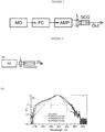
- FIG.1 A generic mid-IR bulk SCG setup is shown in Fig.1 .
- the system consists of a fs master oscillator (MO), frequency conversion stage (FC), fs laser amplifier (AMP), focusing optics (e.g. lens L), bulk medium for continuum generation (SCG).
- the system is configured to spectrally broad mid-IR continuum (Out).
- the frequency conversion stage FC is optional and could be employed prior or after the amplifier (AMP).
- the peak power levels in excess of the critical power cannot be reached directly from the fs oscillator. Therefore, the amplification of fs pulses is required prior to their delivery to SCG stage. Furthermore, many standard fs oscillators (Ti:Sa, fiber-based) emit in near-IR. Therefore, an additional stage for frequency conversion of near-IR fs pulses to mid-IR range is required (prior or after the amplifier stage). On the one hand, the techniques for frequency conversion and amplification of fs pulses are well developed. On the other hand, the overall setup is very complex, bulky and high-cost, which greatly limits the practical use of existing mid-IR bulk SCG sources.
- the present inventors have satisfied that need by constructing a laser system with a single pass amplifier that simultaneously amplifies, spectrally broadens and compresses seed pulses.
- the invention relates to a method of enhancing properties of sub-nanosecond pulses as defined in claim 1 and to a sub-nanosecond, broad spectrum generating laser system as defined in claim 5. Further embodiments are subject of the dependent claims.
- the present invention provides short-pulse, broad spectrum generating laser systems that benefit from an optical scheme configured to amplify and spectrally broaden a seed pulse in a gain media.
- a bulk gain medium having non-linear properties concurrently receives a continuous or discontinuous pump output and a seed pulse.
- Guiding optics is utilized to superimpose the pump and master oscillator emissions on the bulk in a single pass which are emitted from respective optical pump and master oscillator devices. Additional optics is utilized for separating the output pulses from transmitted pump emission.
- the peak power of pulses from the master oscillator approximately equals or exceeds the critical power (PC) for self-focusing in the bulk medium.
- PC critical power
- nonlinear interaction of input pulses from the master oscillator with said bulk results in non-linear optical effects.
- These nonlinear optical effects may include any one or any combination of self-focusing, self-phase modulation, cross-phase modulation, four-wave mixing, filamentation and pulse compression.
- the bulk media comprise TM:II-VI nanocrystals or polycrystals.
- the TM:II-VI nanocrystals or polycrystals are one of Cr:ZnS, Cr:ZnSe, Cr:CdS, Fe:ZnSe or Fe:ZnS
- the pump utilized for the present invention in any of the above formulated aspects, it is preferable that it is configured as a laser selected from one of Er- or Tm- doped fiber, but TM:II-VI lasers are also contemplated within the scope of the invention.
- the pump may operate a continuous wave (CW) regime.
- the present invention allows for the use of a master oscillator within the context of any of the above-mentioned aspects to produce the seed pulses that are input into the bulk.
- the wavelength of the pulses must significantly exceed the bandgap of a material.
- the master oscillator is a laser selected from pico- or femtosecond TM:II-VI lasers.
- the laser system of the present invention can further benefit from additional optical components integrated in structures of any of the above-disclosed aspects.
- the laser system includes at least one dispersive element placed before or after the bulk medium.
- Such dispersive elements may include any one or a combination of a plane-parallel plate, set of dispersive prisms, or dispersive mirror.
- the dispersive element is configured to compensate for the dispersion of said bulk and other components of the system and in another embodiment the dispersive element is configured to control the parameters of the input pulses from the master oscillator.
- the present invention also provides a method implemented by a laser system configured in accordance with any of and a combination of the above disclosed aspects.
- the inventive method allows for enhancing the properties of a pico-second or femtosecond seed pulse by first inputting the seed pulse from a master oscillator into a bulk medium capable of increasing peak power and broadening the spectrum of the seed; and concurrently pumping the bulk medium with an optical pump sufficient to create a laser interaction with the seed pulse in the bulk medium such that output pulses with greater pulse energy and broader spectrum than those of the seed pulse are emitted from the bulk.
- the nonlinear interactions between propagating optical pulses and the bulk medium are enhanced by the laser interactions induced by optically pumping the bulk medium.
- the spectrum of output pulses is significantly broadened in comparison with the spectrum of input seed pulses from the master oscillator.
- the duration of output pulses is significantly shortened in comparison with the duration of input pulses from the master oscillator.
- femtosecond (fs) oscillators based on transition-metal-doped II-VI semiconductors (TM:II-VI) has allowed one to obtain fs optical pulses directly in mid-IR spectral range, thus avoiding the need for complex and bulky setups for frequency conversion of standard near-IR fs oscillators to mid-IR.
- fs femtosecond
- TM:II-VI transition-metal-doped II-VI semiconductors
- ⁇ 0.5 MW peak power which has been obtained directly from mid-IR polycrystalline Cr2+:ZnS fs oscillator, approximately equals the critical power for self-focusing in Cr2+:ZnS, Cr2+:ZnSe and other II-VI semiconductors.
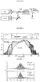
- Figs. 2 (a) and 2 (b) set forth respective optical schematic and the measured spectra of the present invention where a mid-IR fs laser is used as the seed laser and the bulk is any one of the following II-VI materials: Cr2+:ZnS/ZnSe/CdSe.
- Figure 2(a) provides a schematic of the setup consisting of: fs master oscillator (MO), focusing lens (L), bulk Cr2+:ZnS/ZnSe/CdSe material.
- Fig 2(b) illustrates the measured spectra of pulses shown on in logarithmic scale: input (dashed line) and output (solid lines). In this configuration, the bulk is not pumped and as such this considered a "cold amplifier", whereby the only energy imparted into the bulk is from the seed pulses.
- Fig. 3 sets forth an optical schematic of the present invention whereby a "hot amplifier” is used.
- the pump used for his configuration was an Erbium fiber laser sold by IPG Photonics, Oxford, MA, model number ELR-20-1567-LP.
- a "hot amplifier” is bulk that is concurrently pumped and subject to the seed pulse. This setup produces spectral broadening and amplification of fs optical pulses in a single pass.
- the system provided in Fig. 3 comprises a fs master oscillator (MO); focusing optics for MO beam (L1); pump laser (Pump); focusing optics for Pump beam (L2); optics for superimposing Pump and MO beams (e.g.
- dichroic mirror DM1 dichroic mirror DM1; optional optics for beam steering (M); a bulk material, which combines properties of the laser gain medium and nonlinear medium (GM-NM), e.g. polycrystalline Cr2+:ZnS/ZnSe; and optics for separation of the output beam (Out) from the residual pump radiation (e.g. dichroic mirror DM2).
- M optional optics for beam steering
- GM-NM nonlinear medium
- GM-NM nonlinear medium
- Out optics for separation of the output beam (Out) from the residual pump radiation
- the emission from mid-IR fs master oscillator (MO) is superimposed with CW emission of the Er-doped fiber laser (Pump) using a dichroic mirror DM1.
- the MO and Pump beams are focused with the GM-NM - polycrystalline Cr2+:ZnS or Cr2+:ZnSe (GM-NM).
- the latter combines properties of the laser gain medium and the nonlinear medium: (i) optical pumping of GM-NM results in amplification of input pulses from MO (like in conventional laser amplifier); (ii) nonlinearity of GM-NM results in spectral broadening of input pulses; (iii) amplification of pulses during their propagation through GM-NM results in increase of their peak power and, hence, in further spectral broadening, etc. Apparently, the initial spectral broadening is achieved at high enough peak power of the input pulses.
- the device is based on polycrystalline Cr2+:ZnS or Cr2+:ZnSe, which is optically pumped by low cost and efficient cw fiber laser. There is little doubt that the output characteristics of the device can be further significantly improved.
- Fig. 4 sets forth the measured spectra of output pulses.
- 'Cold spectrum' was measured with the pump laser turned off; that is, with a "cold amplifier”.
- the 'hot spectrum' was measured at 20 W CW pump power input concurrent with the seed pulses, such that is was a "hot amplifier” and 7.1 W average output power was an increase from the 1.9 W of the seed.
- the grey lines illustrate spectral broadening with increase of the pump power.
- Top graph shows transmissions of 1 m standard air and of the pump separator (DM2). As can be seen, the obtained spectrum completely fills 2.0-2.5 ⁇ m atmospheric transparency window.
- Fig. 5 provides the measured autocorrelations of output pulses. 'Cold autocorrelation' was measured with the Pump laser turned off; 'hot autocorrelation' was measured at 20 W CW pump power and 7.1 W output power; As can be seen, amplification of input pulses is accompanied by their compression from 44 fs to about 33 fs.
- Fig. 6 provides the measured characteristics of the device vs pump power.
- Top graph compares spectral bandwidth (at -10 dB level) and pulse duration.
- the bottom graph compares gain of the amplifier.
- an increase of the pump power results in (i) spectral broadening, (ii) pulse compression, (iii) increase of output power. It is important to note that amplification of fs pulses occurs as efficiently as amplification of CW laser.
- the master oscillator used in the present invention is shown in Fig. 7 .
- This laser was described in greater detail in PCT/US2015/23232 filed on 30 March 2015 , see also WO2015153391 A1 .
- EDFL Er- doped fiber laser
- An anti-reflective (AR) coated polycrystalline Cr2+:ZnS gain element is mounted in the resonator at normal incidence between two curved mirrors.
- the gain element is 5 mm long with 11% low-signal transmission and is cooled with room temperature water.
- the resonator's legs are unequal with a typical ratio of 2:5.
- the laser has two optical outputs: mid-IR through the output coupler (OC) and SHG trough curved dichroic mirror (DM) with high transmission in SHG wavelength range.
- the reflectivity and the group delay dispersion (GDD) of the optical coatings were optimized in the 2200 - 2700 nm wavelength range. Net GDD of the resonator can be adjusted in discrete steps by changing a type and the number of installed high reflectors (HR) with negative GDD.
- Third order dispersion (TOD) of the gain element was compensated by a dedicated mirror (HR*). The laser was optimized for maximum CW output power.
- the distance between the curved mirrors was then fine-adjusted in order to enable Kerr-Lens mode-locked regime (initiated by OC translation).
Landscapes
- Physics & Mathematics (AREA)
- Electromagnetism (AREA)
- Optics & Photonics (AREA)
- Nonlinear Science (AREA)
- Engineering & Computer Science (AREA)
- Plasma & Fusion (AREA)
- General Physics & Mathematics (AREA)
- Chemical & Material Sciences (AREA)
- Crystallography & Structural Chemistry (AREA)
- Inorganic Chemistry (AREA)
- Ceramic Engineering (AREA)
- Lasers (AREA)
- Optical Modulation, Optical Deflection, Nonlinear Optics, Optical Demodulation, Optical Logic Elements (AREA)
Claims (8)
- Verfahren zum Verbessern von Eigenschaften von Sub-Nanosekunden-Impulsen, wobei das Verfahren umfasst:Erzeugen von Sub-Nanosekunden-gepulstem Eingangssignallicht durch Pico- oder Femtosekunden-TM:II-VI-Laser, die in einem Spektralbereich des mittleren Infrarot emittieren, wobei jeder Sub-Nanosekunden-Eingangsimpuls des Signallichts eine erste Impulsdauer, eine erste Spektralbreite und eine erste Impulsspitzenleistung aufweist;Koppeln des Sub-Nanosekunden-gepulsten Eingangssignallichts mit einer ersten Wellenlänge in ein Bulk-Verstärkungsmedium, dadurch Leiten des Sub-Nanosekunden-gepulsten Eingangssignallichts in einem einzigen Durchlauf durch das Bulk-Verstärkungsmedium, wobei die erste Impulsspitzenleistung wenigstens gleich einer kritischen Leistung (Pc) zum Selbstfokussieren in dem Bulk-Verstärkungsmedium ist, wobei das Bulk-Verstärkungsmedium nichtlineare Eigenschaften aufweist und aus Polykristallen ausgewählt ist, die aus Cr:ZnS, Cr:ZnSe, Cr:CdS, Fe:ZnSe oder Fe:ZnS hergestellt sind;Koppeln von Pumplicht mit einer zweiten Wellenlänge, die von der ersten Wellenlänge verschieden ist, in das Bulk-Verstärkungsmedium, während die Sub-Nanosekunden-Eingangsimpulse dadurch geleitet werden, dadurch Ausgeben von Sub-Nanosekunden-Impulsen mit der ersten Wellenlänge in der Weise, dass jeder ausgegebene Sub-Nanosekundenimpuls aufweist:eine zweite Impulsdauer, die kürzer als die erste Impulsdauer ist,eine zweite Spektralbreite, die größer als die erste Spektralbreite ist, undeine zweite Impulsspitzenleistung, die höher als die erste Impulsspitzenleistung ist; undoptisches Trennen der Ausgangs-Sub-Nanosekunden-Impulse des Signallichts und des Pumplichts.
- Verfahren nach Anspruch 1, wobei das Pumpen des Bulk-Verstärkungsmediums ein Dauerstrichpumpen oder ein gepulstes Pumpen durch einen Pumpfaserlaser, der aus Er- oder Tm-dotieren Faserlasern ausgewählt ist, enthält
- Verfahren nach Anspruch 1, das ferner das optische Überlagern und das Fokussieren des Signallichts und des Pumplichts in dem Bulk-Verstärkungsmedium umfasst.
- Verfahren nach Anspruch 1, wobei das Leiten der Sub-Nanosekunden-Eingangsimpulse durch das Bulk-Verstärkungsmedium die Wechselwirkung zwischen den Sub-Nanosekunden-Eingangsimpulsen und dem Bulk-Medium, dadurch das Erzeugen eines nichtlinearen Effekts, der Selbstfokussierung, Selbstphasenmodulation, Querphasenmodulation oder Vierwellenmischung oder eine Kombination davon enthält, enthält.
- Sub- Nanosekunden- Breitspektrumerzeugungs- Lasersystem, das umfasst:einen Master-Oszillator, der aus Pico- oder Femtosekunden-TM:II-VI-Lasern ausgewählt ist und entlang eines Wegs gepulstes Signallicht von Sub-Nanosekunden-Eingangsimpulsen mit einer ersten Wellenlänge in einem Spektralbereich des mittleren Infrarot emittiert, wobei die Sub-Nanosekunden-Eingangsimpulse jeweils eine erste Impulsdauer, eine erste Spektralbreite und eine erste Impulsspitzenleistung aufweisen;ein nichtlineares Bulk-Verstärkungsmedium ausgangsseitig des Master-Oszillators, wobei das nichtlineare Bulk-Verstärkungsmedium Polykristalle enthält, die aus Cr:ZnS, Cr:ZnSe, Cr:CdS, Fe:ZnSe oder Fe:ZnS hergestellt sind;eine optische Pumpe, die Dauerstrich- oder diskontinuierliches Pumplicht mit einer zweiten Wellenlänge, die von der ersten Wellenlänge verschieden ist, emittiert;eine optische Eingangsanordnung zwischen dem Master-Oszillator und dem nichtlinearen Bulk-Verstärkungsmedium, wobei die optische Eingangsanordnung dafür konfiguriert ist, das gepulste Signal und das Pumplicht in dem Bulk-Verstärkungsmedium in einem einzigen Durchgang zu überlagern und zu fokussieren, so dass das nichtlineare Bulk-Verstärkungsmedium Sub-Nanosekundenimpulse mit der ersten Wellenlänge ausgibt, wobei jeder ausgegebene Sub-Nanosekundenimpuls aufweist:eine zweite Impulsdauer, die kürzer als die erste Impulsdauer ist,eine zweite Spektralbreite, die größer als die erste Spektralbreite ist, undeine zweite Impulsspitzenleistung, die höher als die erste Impulsspitzenleistung ist; undeine optische Ausgangsanordnung, die dafür konfiguriert ist, die Sub-Nanosekunden-Ausgangsimpulse ausgangsseitig des nichtlinearen Bulk-Verstärkungsmediums von dem Pumplicht zu trennen.
- Lasersystem nach Anspruch 5, wobei der Master-Oszillator dafür betreibbar ist, die Eingangs-Sub-Nanosekunden-Impulse jeweils mit einer Spitzenleistung wenigstens gleich der kritischen Leistung (Pc) zu erzeugen, um in dem nichtlinearen Bulk-Verstärkungsmedium einen nichtlinearen Effekt zu erzeugen, der Selbstfokussierung oder Selbstphasenmodulation oder Querphasenmodulation oder Vierwellenmischung oder Filamentierung oder Impulskompression oder eine Kombination dieser enthält.
- Lasersystem nach Anspruch 5, wobei die optische Pumpe aus Er-, Tm-dotierten Faserlasern ausgewählt ist.
- System nach Anspruch 5, das ferner wenigstens ein dispergierendes Element umfasst, das sich eingangsseitig oder ausgangsseitig des nichtlinearen Bulk-Verstärkungsmediums befindet, wobei das dispergierende Element eine planparallele Platte oder ein Satz dispergierender Prismen oder dispergierende Spiegel oder eine Kombination dieser ist, wobei das dispergierende Element dafür konfiguriert ist, Parameter der Sub-Nanosekunden-Eingangsimpulse zu steuern.
Applications Claiming Priority (2)
| Application Number | Priority Date | Filing Date | Title |
|---|---|---|---|
| US201562237821P | 2015-10-06 | 2015-10-06 | |
| PCT/US2016/053008 WO2017062181A1 (en) | 2015-10-06 | 2016-09-22 | Sub-nanosecond broad spectrum generating laser system |
Publications (3)
| Publication Number | Publication Date |
|---|---|
| EP3360209A1 EP3360209A1 (de) | 2018-08-15 |
| EP3360209A4 EP3360209A4 (de) | 2019-07-10 |
| EP3360209B1 true EP3360209B1 (de) | 2020-09-02 |
Family
ID=58488323
Family Applications (1)
| Application Number | Title | Priority Date | Filing Date |
|---|---|---|---|
| EP16854070.6A Active EP3360209B1 (de) | 2015-10-06 | 2016-09-22 | Lasersystem zur erzeugung eines subnanosekundenbreiten spektrums |
Country Status (6)
| Country | Link |
|---|---|
| US (1) | US10483709B2 (de) |
| EP (1) | EP3360209B1 (de) |
| JP (1) | JP6946282B2 (de) |
| KR (1) | KR102550608B1 (de) |
| LT (1) | LT3360209T (de) |
| WO (1) | WO2017062181A1 (de) |
Families Citing this family (8)
| Publication number | Priority date | Publication date | Assignee | Title |
|---|---|---|---|---|
| US10608401B2 (en) * | 2014-04-01 | 2020-03-31 | Ipg Photonics Corporation | Mid-IR Kerr lens mode locked laser with normal incidence mounting of polycrystalline TM:II-VI materials and method for controlling parameters of polycrystalline TM:II-VI Kerr lens mode locked laser |
| WO2017062181A1 (en) * | 2015-10-06 | 2017-04-13 | Ipg Photonics Corporation | Sub-nanosecond broad spectrum generating laser system |
| EP4343989A3 (de) * | 2015-10-06 | 2024-07-31 | IPG Photonics Corporation | Eingängiger laserverstärker mit gepulstem pumpen |
| JP6711600B2 (ja) * | 2015-12-09 | 2020-06-17 | キヤノン株式会社 | 光源装置及び情報取得装置 |
| JP6839787B2 (ja) * | 2017-09-29 | 2021-03-10 | エーエスエムエル ネザーランズ ビー.ブイ. | 放射源 |
| WO2020092707A2 (en) * | 2018-11-01 | 2020-05-07 | Ofs Fitel, Llc | Wavelength-swept light source |
| CN119097413A (zh) | 2019-01-15 | 2024-12-10 | 波士顿科学医学有限公司 | 对准方法和工具 |
| JP2024502021A (ja) * | 2020-12-29 | 2024-01-17 | アイピージー フォトニクス コーポレーション | バルク誘電体と半導体における低閾値スーパーコンティニウム発生 |
Family Cites Families (18)
| Publication number | Priority date | Publication date | Assignee | Title |
|---|---|---|---|---|
| KR960705250A (ko) * | 1993-10-11 | 1996-10-09 | 사이먼 크리스토퍼 로버츠 | 비선형 광 위상스위치 및 그 광 신호 스위칭 방법(optical switching device) |
| US5880877A (en) * | 1997-01-28 | 1999-03-09 | Imra America, Inc. | Apparatus and method for the generation of high-power femtosecond pulses from a fiber amplifier |
| US6181463B1 (en) * | 1997-03-21 | 2001-01-30 | Imra America, Inc. | Quasi-phase-matched parametric chirped pulse amplification systems |
| JP2000340870A (ja) * | 1999-05-27 | 2000-12-08 | Oki Electric Ind Co Ltd | 光ファイバ増幅器および光パルス圧縮装置 |
| JP3536058B2 (ja) * | 2000-02-28 | 2004-06-07 | 独立行政法人理化学研究所 | 短パルス・レーザー光のパルス幅圧縮方法 |
| US7606274B2 (en) * | 2001-09-20 | 2009-10-20 | The Uab Research Foundation | Mid-IR instrument for analyzing a gaseous sample and method for using the same |
| US20090122816A1 (en) * | 2005-09-22 | 2009-05-14 | Lockheed Martin Coherent Technologies, Inc. | Rapidly and electronically broadly tunable IR laser source |
| US8000373B2 (en) * | 2007-11-20 | 2011-08-16 | Itt Manufacturing Enterprises, Inc. | Methods and apparatus for generating RGB laser light |
| TWI408481B (zh) * | 2009-09-23 | 2013-09-11 | Univ Nat Taiwan | 波長可調單程光學參數放大器 |
| GB201001051D0 (en) * | 2010-01-22 | 2010-03-10 | Fianium Ltd | Optical sources |
| US8526772B2 (en) * | 2010-08-26 | 2013-09-03 | The Board Of Trustees Of The University Of Illinois | Compression of polarized supercontinuum pulses generated in birefringent all normal-dispersion photonic crystal fiber |
| FR2989475B1 (fr) * | 2012-04-12 | 2014-12-05 | Amplitude Systemes | Systeme et procede d'amplification optique d'impulsions lumineuses ultra-breves au-dela de la limite de la bande spectrale de gain |
| US9240663B2 (en) * | 2013-11-14 | 2016-01-19 | Coherent, Inc. | Tunable femtosecond laser-pulse source including a super-continuum generator |
| JP6640733B2 (ja) * | 2014-04-01 | 2020-02-05 | アイピージー フォトニクス コーポレーション | 垂直入射取付けの多結晶tm:ii−vi材料を有する中赤外線カーレンズモードロックレーザー及び、多結晶tm:ii−viカーレンズモードロックレーザーのパラメータを制御するための方法 |
| US10608401B2 (en) * | 2014-04-01 | 2020-03-31 | Ipg Photonics Corporation | Mid-IR Kerr lens mode locked laser with normal incidence mounting of polycrystalline TM:II-VI materials and method for controlling parameters of polycrystalline TM:II-VI Kerr lens mode locked laser |
| CN104009376A (zh) * | 2014-05-06 | 2014-08-27 | 北京工业大学 | Cr:Ⅱ-Ⅵ族晶体激光器泵浦的中红外超连续谱光源 |
| EP4343989A3 (de) * | 2015-10-06 | 2024-07-31 | IPG Photonics Corporation | Eingängiger laserverstärker mit gepulstem pumpen |
| WO2017062181A1 (en) * | 2015-10-06 | 2017-04-13 | Ipg Photonics Corporation | Sub-nanosecond broad spectrum generating laser system |
-
2016
- 2016-09-22 WO PCT/US2016/053008 patent/WO2017062181A1/en not_active Ceased
- 2016-09-22 JP JP2018517577A patent/JP6946282B2/ja active Active
- 2016-09-22 EP EP16854070.6A patent/EP3360209B1/de active Active
- 2016-09-22 LT LTEP16854070.6T patent/LT3360209T/lt unknown
- 2016-09-22 US US15/764,686 patent/US10483709B2/en active Active
- 2016-09-22 KR KR1020187009515A patent/KR102550608B1/ko active Active
Non-Patent Citations (1)
| Title |
|---|
| None * |
Also Published As
| Publication number | Publication date |
|---|---|
| EP3360209A4 (de) | 2019-07-10 |
| US10483709B2 (en) | 2019-11-19 |
| LT3360209T (lt) | 2021-01-11 |
| WO2017062181A1 (en) | 2017-04-13 |
| US20180278006A1 (en) | 2018-09-27 |
| KR20180063108A (ko) | 2018-06-11 |
| KR102550608B1 (ko) | 2023-06-30 |
| EP3360209A1 (de) | 2018-08-15 |
| JP2018534615A (ja) | 2018-11-22 |
| JP6946282B2 (ja) | 2021-10-06 |
Similar Documents
| Publication | Publication Date | Title |
|---|---|---|
| EP3360209B1 (de) | Lasersystem zur erzeugung eines subnanosekundenbreiten spektrums | |
| US10216063B2 (en) | Single pass laser amplifier with pulsed pumping | |
| Polyanskiy et al. | Demonstration of a 2 ps, 5 TW peak power, long-wave infrared laser based on chirped-pulse amplification with mixed-isotope CO2 amplifiers | |
| US9184549B2 (en) | Compact coherent high brightness light source for the mid-IR and far IR | |
| CN103762496B (zh) | 基于全固态飞秒激光器的天文光学频率梳装置 | |
| CN111712761B (zh) | 具有可快速调节的中心波长的超短脉冲激光系统 | |
| US8000574B2 (en) | Method of generating supercontinuum optical radiation, supercontinuum optical radiation source, and use thereof | |
| CN110492346B (zh) | 一种二阶非线性晶体的差频过程获取宽带光辐射的方法 | |
| WO2010136761A1 (en) | Optical apparatus | |
| CN101677173B (zh) | 载波相位自稳定的中红外飞秒激光脉冲产生方法及装置 | |
| US10404029B2 (en) | Light source apparatus shaping a waveform of a pump light source and using optical parametric process with information acquisition apparatus using same | |
| Ionin et al. | Mode‐locked CO laser frequency doubling in ZnGeP2 with 25% efficiency | |
| CN118213842A (zh) | 一种红外飞秒脉冲产生装置、其产生方法及超快光纤激光器 | |
| Farinella et al. | Demonstration of thin film compression for short-pulse X-ray generation | |
| CN111146670A (zh) | 一种紫外脉冲激光器 | |
| KR100525566B1 (ko) | 유도 브릴루앙 산란과 2차 라만-스토크스파 발생을 이용한라만 레이저 발진 장치 및 방법 | |
| Vasilye et al. | Long-wave IR femtosecond supercontinuum generation with Cr: ZnS lasers | |
| US20130259437A1 (en) | Pulse excited thz waveguide source based on optical rectification | |
| JP2001066653A (ja) | 超短光パルス発生装置 | |
| CN120497739A (zh) | 双波段调谐的光纤非线性显微光谱混合激发源装置及方法 | |
| Sharping et al. | Pulsed Fiber-Optical Parametric Oscillators in the Near Infrared | |
| Yamane et al. | The development of angularly-dispersed non-collinear optical parametric amplifier for generation of high power optical pulses in monocycle regime | |
| Goulart-Pailo et al. | Full characterization of femtosecond pulses at 1225-1350 nm produced by a high power fiber optical parametric oscillator | |
| Steinmann et al. | Tunable fs Laser Pulses from OPA with MHz Repetition Rate | |
| Loza-Alvarez et al. | Periodically poled RbTiOAsO/sub 4/femtosecond optical parametric oscillator tunable from 1.38 to 1.58/spl mu/m |
Legal Events
| Date | Code | Title | Description |
|---|---|---|---|
| STAA | Information on the status of an ep patent application or granted ep patent |
Free format text: STATUS: THE INTERNATIONAL PUBLICATION HAS BEEN MADE |
|
| PUAI | Public reference made under article 153(3) epc to a published international application that has entered the european phase |
Free format text: ORIGINAL CODE: 0009012 |
|
| STAA | Information on the status of an ep patent application or granted ep patent |
Free format text: STATUS: REQUEST FOR EXAMINATION WAS MADE |
|
| 17P | Request for examination filed |
Effective date: 20180329 |
|
| AK | Designated contracting states |
Kind code of ref document: A1 Designated state(s): AL AT BE BG CH CY CZ DE DK EE ES FI FR GB GR HR HU IE IS IT LI LT LU LV MC MK MT NL NO PL PT RO RS SE SI SK SM TR |
|
| AX | Request for extension of the european patent |
Extension state: BA ME |
|
| DAV | Request for validation of the european patent (deleted) | ||
| DAX | Request for extension of the european patent (deleted) | ||
| A4 | Supplementary search report drawn up and despatched |
Effective date: 20190613 |
|
| RIC1 | Information provided on ipc code assigned before grant |
Ipc: H01S 3/16 20060101ALI20190606BHEP Ipc: H01S 3/108 20060101AFI20190606BHEP Ipc: H01S 3/094 20060101ALN20190606BHEP Ipc: H01S 3/23 20060101ALI20190606BHEP |
|
| RIC1 | Information provided on ipc code assigned before grant |
Ipc: H01S 3/23 20060101ALI20200212BHEP Ipc: H01S 3/16 20060101ALI20200212BHEP Ipc: H01S 3/108 20060101AFI20200212BHEP Ipc: H01S 3/094 20060101ALN20200212BHEP |
|
| GRAP | Despatch of communication of intention to grant a patent |
Free format text: ORIGINAL CODE: EPIDOSNIGR1 |
|
| STAA | Information on the status of an ep patent application or granted ep patent |
Free format text: STATUS: GRANT OF PATENT IS INTENDED |
|
| INTG | Intention to grant announced |
Effective date: 20200415 |
|
| GRAS | Grant fee paid |
Free format text: ORIGINAL CODE: EPIDOSNIGR3 |
|
| GRAA | (expected) grant |
Free format text: ORIGINAL CODE: 0009210 |
|
| STAA | Information on the status of an ep patent application or granted ep patent |
Free format text: STATUS: THE PATENT HAS BEEN GRANTED |
|
| AK | Designated contracting states |
Kind code of ref document: B1 Designated state(s): AL AT BE BG CH CY CZ DE DK EE ES FI FR GB GR HR HU IE IS IT LI LT LU LV MC MK MT NL NO PL PT RO RS SE SI SK SM TR |
|
| REG | Reference to a national code |
Ref country code: GB Ref legal event code: FG4D |
|
| REG | Reference to a national code |
Ref country code: AT Ref legal event code: REF Ref document number: 1309902 Country of ref document: AT Kind code of ref document: T Effective date: 20200915 Ref country code: CH Ref legal event code: EP |
|
| REG | Reference to a national code |
Ref country code: DE Ref legal event code: R096 Ref document number: 602016043448 Country of ref document: DE |
|
| REG | Reference to a national code |
Ref country code: IE Ref legal event code: FG4D |
|
| REG | Reference to a national code |
Ref country code: CH Ref legal event code: NV Representative=s name: BOVARD AG PATENT- UND MARKENANWAELTE, CH Ref country code: SE Ref legal event code: TRGR |
|
| REG | Reference to a national code |
Ref country code: NL Ref legal event code: FP |
|
| PG25 | Lapsed in a contracting state [announced via postgrant information from national office to epo] |
Ref country code: HR Free format text: LAPSE BECAUSE OF FAILURE TO SUBMIT A TRANSLATION OF THE DESCRIPTION OR TO PAY THE FEE WITHIN THE PRESCRIBED TIME-LIMIT Effective date: 20200902 Ref country code: GR Free format text: LAPSE BECAUSE OF FAILURE TO SUBMIT A TRANSLATION OF THE DESCRIPTION OR TO PAY THE FEE WITHIN THE PRESCRIBED TIME-LIMIT Effective date: 20201203 Ref country code: NO Free format text: LAPSE BECAUSE OF FAILURE TO SUBMIT A TRANSLATION OF THE DESCRIPTION OR TO PAY THE FEE WITHIN THE PRESCRIBED TIME-LIMIT Effective date: 20201202 Ref country code: BG Free format text: LAPSE BECAUSE OF FAILURE TO SUBMIT A TRANSLATION OF THE DESCRIPTION OR TO PAY THE FEE WITHIN THE PRESCRIBED TIME-LIMIT Effective date: 20201202 Ref country code: FI Free format text: LAPSE BECAUSE OF FAILURE TO SUBMIT A TRANSLATION OF THE DESCRIPTION OR TO PAY THE FEE WITHIN THE PRESCRIBED TIME-LIMIT Effective date: 20200902 |
|
| PG25 | Lapsed in a contracting state [announced via postgrant information from national office to epo] |
Ref country code: LV Free format text: LAPSE BECAUSE OF FAILURE TO SUBMIT A TRANSLATION OF THE DESCRIPTION OR TO PAY THE FEE WITHIN THE PRESCRIBED TIME-LIMIT Effective date: 20200902 Ref country code: PL Free format text: LAPSE BECAUSE OF FAILURE TO SUBMIT A TRANSLATION OF THE DESCRIPTION OR TO PAY THE FEE WITHIN THE PRESCRIBED TIME-LIMIT Effective date: 20200902 Ref country code: RS Free format text: LAPSE BECAUSE OF FAILURE TO SUBMIT A TRANSLATION OF THE DESCRIPTION OR TO PAY THE FEE WITHIN THE PRESCRIBED TIME-LIMIT Effective date: 20200902 |
|
| PG25 | Lapsed in a contracting state [announced via postgrant information from national office to epo] |
Ref country code: RO Free format text: LAPSE BECAUSE OF FAILURE TO SUBMIT A TRANSLATION OF THE DESCRIPTION OR TO PAY THE FEE WITHIN THE PRESCRIBED TIME-LIMIT Effective date: 20200902 Ref country code: PT Free format text: LAPSE BECAUSE OF FAILURE TO SUBMIT A TRANSLATION OF THE DESCRIPTION OR TO PAY THE FEE WITHIN THE PRESCRIBED TIME-LIMIT Effective date: 20210104 Ref country code: CZ Free format text: LAPSE BECAUSE OF FAILURE TO SUBMIT A TRANSLATION OF THE DESCRIPTION OR TO PAY THE FEE WITHIN THE PRESCRIBED TIME-LIMIT Effective date: 20200902 Ref country code: EE Free format text: LAPSE BECAUSE OF FAILURE TO SUBMIT A TRANSLATION OF THE DESCRIPTION OR TO PAY THE FEE WITHIN THE PRESCRIBED TIME-LIMIT Effective date: 20200902 Ref country code: SM Free format text: LAPSE BECAUSE OF FAILURE TO SUBMIT A TRANSLATION OF THE DESCRIPTION OR TO PAY THE FEE WITHIN THE PRESCRIBED TIME-LIMIT Effective date: 20200902 |
|
| PG25 | Lapsed in a contracting state [announced via postgrant information from national office to epo] |
Ref country code: IS Free format text: LAPSE BECAUSE OF FAILURE TO SUBMIT A TRANSLATION OF THE DESCRIPTION OR TO PAY THE FEE WITHIN THE PRESCRIBED TIME-LIMIT Effective date: 20210102 Ref country code: ES Free format text: LAPSE BECAUSE OF FAILURE TO SUBMIT A TRANSLATION OF THE DESCRIPTION OR TO PAY THE FEE WITHIN THE PRESCRIBED TIME-LIMIT Effective date: 20200902 Ref country code: AL Free format text: LAPSE BECAUSE OF FAILURE TO SUBMIT A TRANSLATION OF THE DESCRIPTION OR TO PAY THE FEE WITHIN THE PRESCRIBED TIME-LIMIT Effective date: 20200902 |
|
| REG | Reference to a national code |
Ref country code: DE Ref legal event code: R097 Ref document number: 602016043448 Country of ref document: DE |
|
| REG | Reference to a national code |
Ref country code: BE Ref legal event code: MM Effective date: 20200930 |
|
| PG25 | Lapsed in a contracting state [announced via postgrant information from national office to epo] |
Ref country code: LU Free format text: LAPSE BECAUSE OF NON-PAYMENT OF DUE FEES Effective date: 20200922 Ref country code: MC Free format text: LAPSE BECAUSE OF FAILURE TO SUBMIT A TRANSLATION OF THE DESCRIPTION OR TO PAY THE FEE WITHIN THE PRESCRIBED TIME-LIMIT Effective date: 20200902 Ref country code: SK Free format text: LAPSE BECAUSE OF FAILURE TO SUBMIT A TRANSLATION OF THE DESCRIPTION OR TO PAY THE FEE WITHIN THE PRESCRIBED TIME-LIMIT Effective date: 20200902 |
|
| PLBE | No opposition filed within time limit |
Free format text: ORIGINAL CODE: 0009261 |
|
| STAA | Information on the status of an ep patent application or granted ep patent |
Free format text: STATUS: NO OPPOSITION FILED WITHIN TIME LIMIT |
|
| 26N | No opposition filed |
Effective date: 20210603 |
|
| PG25 | Lapsed in a contracting state [announced via postgrant information from national office to epo] |
Ref country code: DK Free format text: LAPSE BECAUSE OF FAILURE TO SUBMIT A TRANSLATION OF THE DESCRIPTION OR TO PAY THE FEE WITHIN THE PRESCRIBED TIME-LIMIT Effective date: 20200902 Ref country code: BE Free format text: LAPSE BECAUSE OF NON-PAYMENT OF DUE FEES Effective date: 20200930 Ref country code: SI Free format text: LAPSE BECAUSE OF FAILURE TO SUBMIT A TRANSLATION OF THE DESCRIPTION OR TO PAY THE FEE WITHIN THE PRESCRIBED TIME-LIMIT Effective date: 20200902 Ref country code: IE Free format text: LAPSE BECAUSE OF NON-PAYMENT OF DUE FEES Effective date: 20200922 |
|
| REG | Reference to a national code |
Ref country code: AT Ref legal event code: UEP Ref document number: 1309902 Country of ref document: AT Kind code of ref document: T Effective date: 20200902 |
|
| PG25 | Lapsed in a contracting state [announced via postgrant information from national office to epo] |
Ref country code: TR Free format text: LAPSE BECAUSE OF FAILURE TO SUBMIT A TRANSLATION OF THE DESCRIPTION OR TO PAY THE FEE WITHIN THE PRESCRIBED TIME-LIMIT Effective date: 20200902 Ref country code: MT Free format text: LAPSE BECAUSE OF FAILURE TO SUBMIT A TRANSLATION OF THE DESCRIPTION OR TO PAY THE FEE WITHIN THE PRESCRIBED TIME-LIMIT Effective date: 20200902 Ref country code: CY Free format text: LAPSE BECAUSE OF FAILURE TO SUBMIT A TRANSLATION OF THE DESCRIPTION OR TO PAY THE FEE WITHIN THE PRESCRIBED TIME-LIMIT Effective date: 20200902 |
|
| PG25 | Lapsed in a contracting state [announced via postgrant information from national office to epo] |
Ref country code: MK Free format text: LAPSE BECAUSE OF FAILURE TO SUBMIT A TRANSLATION OF THE DESCRIPTION OR TO PAY THE FEE WITHIN THE PRESCRIBED TIME-LIMIT Effective date: 20200902 |
|
| PGFP | Annual fee paid to national office [announced via postgrant information from national office to epo] |
Ref country code: NL Payment date: 20250820 Year of fee payment: 10 |
|
| REG | Reference to a national code |
Ref country code: CH Ref legal event code: U11 Free format text: ST27 STATUS EVENT CODE: U-0-0-U10-U11 (AS PROVIDED BY THE NATIONAL OFFICE) Effective date: 20251001 |
|
| PGFP | Annual fee paid to national office [announced via postgrant information from national office to epo] |
Ref country code: LT Payment date: 20250820 Year of fee payment: 10 Ref country code: DE Payment date: 20250820 Year of fee payment: 10 |
|
| PGFP | Annual fee paid to national office [announced via postgrant information from national office to epo] |
Ref country code: IT Payment date: 20250820 Year of fee payment: 10 |
|
| PGFP | Annual fee paid to national office [announced via postgrant information from national office to epo] |
Ref country code: GB Payment date: 20250822 Year of fee payment: 10 |
|
| PGFP | Annual fee paid to national office [announced via postgrant information from national office to epo] |
Ref country code: FR Payment date: 20250820 Year of fee payment: 10 Ref country code: AT Payment date: 20250822 Year of fee payment: 10 |
|
| PGFP | Annual fee paid to national office [announced via postgrant information from national office to epo] |
Ref country code: SE Payment date: 20250820 Year of fee payment: 10 |
|
| PGFP | Annual fee paid to national office [announced via postgrant information from national office to epo] |
Ref country code: CH Payment date: 20251001 Year of fee payment: 10 |