EP3359794B1 - Dispositif de lubrification d'un palier recevant un arbre rotatif d'un élément d'un circuit fermé fonctionnant selon un cycle de rankine et procédé utilisant un tel dispositif - Google Patents
Dispositif de lubrification d'un palier recevant un arbre rotatif d'un élément d'un circuit fermé fonctionnant selon un cycle de rankine et procédé utilisant un tel dispositif Download PDFInfo
- Publication number
- EP3359794B1 EP3359794B1 EP16766008.3A EP16766008A EP3359794B1 EP 3359794 B1 EP3359794 B1 EP 3359794B1 EP 16766008 A EP16766008 A EP 16766008A EP 3359794 B1 EP3359794 B1 EP 3359794B1
- Authority
- EP
- European Patent Office
- Prior art keywords
- lubrication
- fluid
- bearing
- working fluid
- duct
- Prior art date
- Legal status (The legal status is an assumption and is not a legal conclusion. Google has not performed a legal analysis and makes no representation as to the accuracy of the status listed.)
- Active
Links
- 230000001050 lubricating effect Effects 0.000 title claims description 18
- 238000000034 method Methods 0.000 title claims description 11
- 239000012530 fluid Substances 0.000 claims description 93
- 238000005461 lubrication Methods 0.000 claims description 62
- 239000007788 liquid Substances 0.000 claims description 14
- 238000001816 cooling Methods 0.000 claims description 12
- 230000006835 compression Effects 0.000 claims description 6
- 238000007906 compression Methods 0.000 claims description 6
- 230000005679 Peltier effect Effects 0.000 claims description 5
- 239000000203 mixture Substances 0.000 claims description 4
- 238000002347 injection Methods 0.000 claims description 3
- 239000007924 injection Substances 0.000 claims description 3
- 125000006850 spacer group Chemical group 0.000 claims description 3
- 230000001105 regulatory effect Effects 0.000 claims description 2
- 238000011144 upstream manufacturing Methods 0.000 claims description 2
- 239000010687 lubricating oil Substances 0.000 description 4
- 238000002485 combustion reaction Methods 0.000 description 3
- 238000009833 condensation Methods 0.000 description 3
- 230000005494 condensation Effects 0.000 description 3
- 239000012809 cooling fluid Substances 0.000 description 3
- QGZKDVFQNNGYKY-UHFFFAOYSA-N Ammonia Chemical compound N QGZKDVFQNNGYKY-UHFFFAOYSA-N 0.000 description 2
- CURLTUGMZLYLDI-UHFFFAOYSA-N Carbon dioxide Chemical compound O=C=O CURLTUGMZLYLDI-UHFFFAOYSA-N 0.000 description 2
- LFQSCWFLJHTTHZ-UHFFFAOYSA-N Ethanol Chemical compound CCO LFQSCWFLJHTTHZ-UHFFFAOYSA-N 0.000 description 2
- 238000001704 evaporation Methods 0.000 description 2
- 230000008020 evaporation Effects 0.000 description 2
- 239000007789 gas Substances 0.000 description 2
- 239000013529 heat transfer fluid Substances 0.000 description 2
- 239000000243 solution Substances 0.000 description 2
- 238000009834 vaporization Methods 0.000 description 2
- 230000008016 vaporization Effects 0.000 description 2
- XLYOFNOQVPJJNP-UHFFFAOYSA-N water Substances O XLYOFNOQVPJJNP-UHFFFAOYSA-N 0.000 description 2
- 230000003213 activating effect Effects 0.000 description 1
- 229910021529 ammonia Inorganic materials 0.000 description 1
- 239000001273 butane Substances 0.000 description 1
- 229910002092 carbon dioxide Inorganic materials 0.000 description 1
- 239000001569 carbon dioxide Substances 0.000 description 1
- 230000015556 catabolic process Effects 0.000 description 1
- 230000001276 controlling effect Effects 0.000 description 1
- 238000006731 degradation reaction Methods 0.000 description 1
- 230000008014 freezing Effects 0.000 description 1
- 238000007710 freezing Methods 0.000 description 1
- 238000010438 heat treatment Methods 0.000 description 1
- 238000009434 installation Methods 0.000 description 1
- 239000007791 liquid phase Substances 0.000 description 1
- IJDNQMDRQITEOD-UHFFFAOYSA-N n-butane Chemical compound CCCC IJDNQMDRQITEOD-UHFFFAOYSA-N 0.000 description 1
- OFBQJSOFQDEBGM-UHFFFAOYSA-N n-pentane Natural products CCCCC OFBQJSOFQDEBGM-UHFFFAOYSA-N 0.000 description 1
- 230000000750 progressive effect Effects 0.000 description 1
- 230000007704 transition Effects 0.000 description 1
Images
Classifications
-
- F—MECHANICAL ENGINEERING; LIGHTING; HEATING; WEAPONS; BLASTING
- F02—COMBUSTION ENGINES; HOT-GAS OR COMBUSTION-PRODUCT ENGINE PLANTS
- F02G—HOT GAS OR COMBUSTION-PRODUCT POSITIVE-DISPLACEMENT ENGINE PLANTS; USE OF WASTE HEAT OF COMBUSTION ENGINES; NOT OTHERWISE PROVIDED FOR
- F02G5/00—Profiting from waste heat of combustion engines, not otherwise provided for
- F02G5/02—Profiting from waste heat of exhaust gases
-
- F—MECHANICAL ENGINEERING; LIGHTING; HEATING; WEAPONS; BLASTING
- F01—MACHINES OR ENGINES IN GENERAL; ENGINE PLANTS IN GENERAL; STEAM ENGINES
- F01D—NON-POSITIVE DISPLACEMENT MACHINES OR ENGINES, e.g. STEAM TURBINES
- F01D25/00—Component parts, details, or accessories, not provided for in, or of interest apart from, other groups
- F01D25/08—Cooling; Heating; Heat-insulation
- F01D25/12—Cooling
- F01D25/125—Cooling of bearings
-
- F—MECHANICAL ENGINEERING; LIGHTING; HEATING; WEAPONS; BLASTING
- F01—MACHINES OR ENGINES IN GENERAL; ENGINE PLANTS IN GENERAL; STEAM ENGINES
- F01D—NON-POSITIVE DISPLACEMENT MACHINES OR ENGINES, e.g. STEAM TURBINES
- F01D25/00—Component parts, details, or accessories, not provided for in, or of interest apart from, other groups
- F01D25/18—Lubricating arrangements
-
- F—MECHANICAL ENGINEERING; LIGHTING; HEATING; WEAPONS; BLASTING
- F01—MACHINES OR ENGINES IN GENERAL; ENGINE PLANTS IN GENERAL; STEAM ENGINES
- F01K—STEAM ENGINE PLANTS; STEAM ACCUMULATORS; ENGINE PLANTS NOT OTHERWISE PROVIDED FOR; ENGINES USING SPECIAL WORKING FLUIDS OR CYCLES
- F01K17/00—Using steam or condensate extracted or exhausted from steam engine plant
-
- F—MECHANICAL ENGINEERING; LIGHTING; HEATING; WEAPONS; BLASTING
- F01—MACHINES OR ENGINES IN GENERAL; ENGINE PLANTS IN GENERAL; STEAM ENGINES
- F01K—STEAM ENGINE PLANTS; STEAM ACCUMULATORS; ENGINE PLANTS NOT OTHERWISE PROVIDED FOR; ENGINES USING SPECIAL WORKING FLUIDS OR CYCLES
- F01K23/00—Plants characterised by more than one engine delivering power external to the plant, the engines being driven by different fluids
- F01K23/02—Plants characterised by more than one engine delivering power external to the plant, the engines being driven by different fluids the engine cycles being thermally coupled
- F01K23/06—Plants characterised by more than one engine delivering power external to the plant, the engines being driven by different fluids the engine cycles being thermally coupled combustion heat from one cycle heating the fluid in another cycle
- F01K23/065—Plants characterised by more than one engine delivering power external to the plant, the engines being driven by different fluids the engine cycles being thermally coupled combustion heat from one cycle heating the fluid in another cycle the combustion taking place in an internal combustion piston engine, e.g. a diesel engine
-
- F—MECHANICAL ENGINEERING; LIGHTING; HEATING; WEAPONS; BLASTING
- F01—MACHINES OR ENGINES IN GENERAL; ENGINE PLANTS IN GENERAL; STEAM ENGINES
- F01K—STEAM ENGINE PLANTS; STEAM ACCUMULATORS; ENGINE PLANTS NOT OTHERWISE PROVIDED FOR; ENGINES USING SPECIAL WORKING FLUIDS OR CYCLES
- F01K7/00—Steam engine plants characterised by the use of specific types of engine; Plants or engines characterised by their use of special steam systems, cycles or processes; Control means specially adapted for such systems, cycles or processes; Use of withdrawn or exhaust steam for feed-water heating
- F01K7/16—Steam engine plants characterised by the use of specific types of engine; Plants or engines characterised by their use of special steam systems, cycles or processes; Control means specially adapted for such systems, cycles or processes; Use of withdrawn or exhaust steam for feed-water heating the engines being only of turbine type
-
- F—MECHANICAL ENGINEERING; LIGHTING; HEATING; WEAPONS; BLASTING
- F01—MACHINES OR ENGINES IN GENERAL; ENGINE PLANTS IN GENERAL; STEAM ENGINES
- F01M—LUBRICATING OF MACHINES OR ENGINES IN GENERAL; LUBRICATING INTERNAL COMBUSTION ENGINES; CRANKCASE VENTILATING
- F01M5/00—Heating, cooling, or controlling temperature of lubricant; Lubrication means facilitating engine starting
- F01M5/002—Cooling
-
- F—MECHANICAL ENGINEERING; LIGHTING; HEATING; WEAPONS; BLASTING
- F01—MACHINES OR ENGINES IN GENERAL; ENGINE PLANTS IN GENERAL; STEAM ENGINES
- F01K—STEAM ENGINE PLANTS; STEAM ACCUMULATORS; ENGINE PLANTS NOT OTHERWISE PROVIDED FOR; ENGINES USING SPECIAL WORKING FLUIDS OR CYCLES
- F01K25/00—Plants or engines characterised by use of special working fluids, not otherwise provided for; Plants operating in closed cycles and not otherwise provided for
- F01K25/08—Plants or engines characterised by use of special working fluids, not otherwise provided for; Plants operating in closed cycles and not otherwise provided for using special vapours
- F01K25/10—Plants or engines characterised by use of special working fluids, not otherwise provided for; Plants operating in closed cycles and not otherwise provided for using special vapours the vapours being cold, e.g. ammonia, carbon dioxide, ether
- F01K25/106—Ammonia
-
- F—MECHANICAL ENGINEERING; LIGHTING; HEATING; WEAPONS; BLASTING
- F01—MACHINES OR ENGINES IN GENERAL; ENGINE PLANTS IN GENERAL; STEAM ENGINES
- F01M—LUBRICATING OF MACHINES OR ENGINES IN GENERAL; LUBRICATING INTERNAL COMBUSTION ENGINES; CRANKCASE VENTILATING
- F01M5/00—Heating, cooling, or controlling temperature of lubricant; Lubrication means facilitating engine starting
- F01M5/02—Conditioning lubricant for aiding engine starting, e.g. heating
- F01M5/025—Conditioning lubricant for aiding engine starting, e.g. heating by prelubricating, e.g. using an accumulator
-
- F—MECHANICAL ENGINEERING; LIGHTING; HEATING; WEAPONS; BLASTING
- F16—ENGINEERING ELEMENTS AND UNITS; GENERAL MEASURES FOR PRODUCING AND MAINTAINING EFFECTIVE FUNCTIONING OF MACHINES OR INSTALLATIONS; THERMAL INSULATION IN GENERAL
- F16C—SHAFTS; FLEXIBLE SHAFTS; ELEMENTS OR CRANKSHAFT MECHANISMS; ROTARY BODIES OTHER THAN GEARING ELEMENTS; BEARINGS
- F16C33/00—Parts of bearings; Special methods for making bearings or parts thereof
- F16C33/02—Parts of sliding-contact bearings
- F16C33/04—Brasses; Bushes; Linings
- F16C33/06—Sliding surface mainly made of metal
- F16C33/10—Construction relative to lubrication
- F16C33/1025—Construction relative to lubrication with liquid, e.g. oil, as lubricant
- F16C33/1045—Details of supply of the liquid to the bearing
- F16C33/105—Conditioning, e.g. metering, cooling, filtering
-
- F—MECHANICAL ENGINEERING; LIGHTING; HEATING; WEAPONS; BLASTING
- F16—ENGINEERING ELEMENTS AND UNITS; GENERAL MEASURES FOR PRODUCING AND MAINTAINING EFFECTIVE FUNCTIONING OF MACHINES OR INSTALLATIONS; THERMAL INSULATION IN GENERAL
- F16N—LUBRICATING
- F16N2260/00—Fail safe
- F16N2260/40—Pre-lubrication
-
- Y—GENERAL TAGGING OF NEW TECHNOLOGICAL DEVELOPMENTS; GENERAL TAGGING OF CROSS-SECTIONAL TECHNOLOGIES SPANNING OVER SEVERAL SECTIONS OF THE IPC; TECHNICAL SUBJECTS COVERED BY FORMER USPC CROSS-REFERENCE ART COLLECTIONS [XRACs] AND DIGESTS
- Y02—TECHNOLOGIES OR APPLICATIONS FOR MITIGATION OR ADAPTATION AGAINST CLIMATE CHANGE
- Y02T—CLIMATE CHANGE MITIGATION TECHNOLOGIES RELATED TO TRANSPORTATION
- Y02T10/00—Road transport of goods or passengers
- Y02T10/10—Internal combustion engine [ICE] based vehicles
- Y02T10/12—Improving ICE efficiencies
Definitions
- the present invention relates to a device for lubricating a bearing receiving a rotary shaft of an element of a closed circuit operating according to a Rankine cycle and to a method using such a device.
- It relates more particularly but not exclusively to a device for lubricating a ball bearing bearing supporting the shaft of the turbine that the circuit comprises.
- the Rankine cycle is a thermodynamic cycle by which heat from an external heat source is transmitted to a closed circuit which contains a working fluid.
- This cycle generally breaks down into a step during which the low freezing point working fluid is compressed isentropically, followed by a step where this compressed fluid is heated and vaporized in contact with a heat source. This vapor is then expanded, during another step, isentropically in an expansion machine, then, in a last step, this expanded vapor is cooled and condensed in contact with a cold source.
- the circuit comprises a pump for compressing the working fluid in liquid form and circulating it in the circuit, a heat exchanger (or evaporator) which is swept by a hot fluid to carry out at least partial vaporization.
- compressed fluid an expansion machine to expand the steam, such as a turbine, which transforms the energy of this steam into another energy, such as mechanical or electrical energy, and another heat exchanger (or condenser) thanks to to which the heat contained in the vapor is transferred to a cold source, generally a cooling fluid or the outside air which sweeps this condenser, to transform this vapor into a liquid.
- the bearings of the expansion machine need to be lubricated to ensure the free rotation of the shaft of the expansion machine in these bearings.
- This pollution results in a degradation of the performance of the working circuit, by the loss of the thermodynamic qualities of the working fluid and by the fouling of the heat exchangers.
- One of the known solutions consists in replacing the lubricating oil with the working fluid to ensure the lubricating function.
- the leaks between the two circuits do not lead to pollution of the working fluid, but to a mixture between the working fluid with a “thermodynamic vocation” and this same working fluid with a “lubricating vocation”.
- the drawback lies in the fact that the working fluid generally exhibits poor lubricating qualities.
- the working fluid has a propensity to vaporize easily and, in this physical state, it does not perform any lubricating function.
- the present invention proposes to remedy the aforementioned drawbacks by virtue of a lubricating device which makes it possible to control the state of the working fluid in order to ensure that it does not vaporize before having performed its lubricating function of the bearings.
- the invention relates to a device for lubricating at least one bearing receiving a rotary shaft of an element of a closed circuit operating according to a Rankine cycle, said circuit comprising a compression / circulation pump of a working fluid in liquid form, a heat exchanger swept by a hot source for the evaporation of said fluid, means for expanding the fluid in vapor form, a cooling exchanger swept by a cold source for the condensation of the working fluid, a working fluid reservoir, working fluid circulation pipes and a lubrication circuit for lubricating said bearing, characterized in that the lubrication circuit comprises a lubrication pipe connected to the closed circuit and comprising sub-cooling means fluid circulating in said lubrication line.
- the lubrication line can originate from one of the lines located between the tank and the heat exchanger.
- the lubrication line may carry a regulator and / or a pressure and / or flow limiter.
- the lubrication line can originate from the line upstream of the compression / circulation pump.
- the lubrication line may include a circulation pump.
- the lubrication line may include a temperature sensor.
- the lubrication line may include a pressure sensor.
- the sub-cooling means may include a Peltier effect device.
- the bearing may include a circumferential diffuser for the working fluid.
- the diffuser may include a spacer provided with injection points regularly distributed circumferentially.
- the working fluid can be an organic fluid or mixtures of organic fluids.
- the expansion means may comprise a turbine (30) and in that the bearing receiving the rotary shaft is the bearing of the turbine.
- the invention also relates to a method of lubricating at least one bearing receiving a rotary shaft of an element of a closed circuit operating according to a Rankine cycle, said circuit comprising a compression / circulation pump for a working fluid. in liquid form, a heat exchanger swept by a hot source for the evaporation of said fluid, means for expanding the fluid in vapor form, a cooling exchanger swept by a cold source for the condensation of the working fluid, a storage tank working fluid, pipes for circulating the working fluid, and a lubrication circuit for lubricating said bearing, characterized in that it consists in diverting part of the working fluid from the closed circuit to the bearing and in subcooling this fluid before its admission into said bearing.
- the method may consist in regulating and / or limiting the pressure and / or the flow rate of the fluid in order to control the quantity of fluid admitted into the bearing.
- the method may consist in starting up a circulation pump placed on the pipe for lubricating the bearings and activating the sub-cooling means before starting up the compression / circulation pump so as to ensure lubrication. of said bearing.
- the method may consist in distributing the fluid over the entire circumference of the bearing.
- the Rankine cycle closed circuit 10 is advantageously of the ORC (Organic Rankine Cycle) type which uses an organic fluid or a mixture of organic fluids, such as butane, ethanol, hydrofluorocarbons or carbon dioxide.
- ORC Organic Rankine Cycle
- the closed circuit can operate with a non-organic fluid such as ammonia or water.
- This circuit comprises a pump 12 for circulating and compressing the working fluid, called a pump in the remainder of the description, with an inlet 14 for the working fluid in liquid form and an outlet 16 for this working fluid also in liquid form but compressed under high pressure.
- This pump is advantageously driven in rotation by any means; like an electric motor (not shown).
- This circuit also comprises a heat exchanger 18, called an evaporator, through which the working fluid compressed between an inlet 20 of this liquid fluid and an outlet 22 through which the working fluid leaves this evaporator in the form of compressed vapor.
- This evaporator is traversed by a hot source 24 in liquid or gaseous form.
- This hot source can come from the exhaust gases circulating in the exhaust line 26 of an internal combustion engine 28, the cooling fluid of an internal combustion engine, the cooling fluid of an industrial furnace, or heat transfer fluid heated in thermal installations or by a burner.
- This circuit also comprises an expansion machine 30 receiving through its inlet 32 the working fluid in the form of high pressure compressed steam, this fluid leaving through the outlet 34 of this machine in the form of low pressure expanded steam.
- this expansion machine is in the form of an expansion turbine, the rotor shaft of which is placed on two bearings 36a and 36b and which is driven in rotation by the working fluid in the form of steam by controlling a rotation of a link shaft 37.
- this shaft makes it possible to transmit the recovered energy to any transformer device, such as for example an electric generator 38.
- the circuit also comprises a cooling exchanger 40, or condenser, with an inlet 42 for the expanded low-pressure steam and an outlet 44 for the working fluid transformed into liquid form after it has passed through this condenser.
- This condenser is swept by a cold source, generally a flow of cold air (Arrow F) generally at room temperature, so as to cool the expanded vapor so that it condenses and turns into a liquid.
- a cold source generally a flow of cold air (Arrow F) generally at room temperature
- any other cold source of cooling such as water, can be used to ensure the condensation of the vapor.
- This circuit also comprises a closed reservoir 46 which makes it possible to keep the working fluid in the liquid state and, preferably, a filter 48, such as a cartridge filter, to filter the working fluid leaving the reservoir before its introduction into the pump.
- a filter 48 such as a cartridge filter
- the various elements of the circuit are interconnected by fluid circulation pipes 50, 52, 54, 56, 58, 60 allowing the pump to be successively connected with the evaporator (evaporator pipe 50), the evaporator with the turbine (turbine pipe 52), this turbine with the condenser (turbine pipe condenser 54), the condenser with the tank (tank line 56), the tank to the filter (filter line 58) and the filter to the pump (pump line 60) so that the working fluid flows in the direction indicated by arrows A.
- the closed circuit comprises a lubrication circuit 62 using the fluid which circulates therein to lubricate at least one bearing receiving a rotary shaft of an element of the closed circuit and more particularly the bearings 36a, 36b of the turbine 30.
- this lubrication circuit can be used to lubricate the bearings of any other rotating element of the closed circuit, such as the pump 12.
- This lubrication circuit comprises a lubrication pipe 64 which originates on one of the pipes located between the reservoir 46 and the evaporator 18 and which ends at the bearings 36a, 36b of the turbine 30.
- this lubrication line originates on the pump line 60 between the filter and the pump 12.
- This pipe carries in the direction of circulation according to arrow A ', a circulation pump 68, or lubrication pump, making it possible to circulate this fluid in the pipe and means for sub-cooling 66 of the fluid circulating in the lubrication pipe. .
- the cooling means comprise an electrically powered Peltier effect device.
- the pipe also carries, between the pump 68 and the bearings, a temperature sensor T and a pressure sensor P of the fluid circulating in this pipe.
- the heat transfer fluid which is filtered by the filter 48 after leaving the reservoir 46 and which is in the liquid phase, is partly diverted into the lubrication pipe to circulate there under the impulse of the lubrication pump 68.
- This pump also makes it possible to regulate the flow of fluid intended for the lubrication of the bearings.
- this fluid is sub-cooled by the Peltier effect device before being introduced into the bearings 36a and 36b.
- the sub-cooling device makes it possible, if necessary, to regulate the temperature of the fluid intended for lubrication by means of the sensors, it has the essential role of delaying the transition to the gaseous state of the fluid after it has been injected, in the liquid state, into the bearings.
- the circulation pump 68 intended for the lubrication of the bearings and the Peltier effect device are started up before the start-up of the main pump 12 of the closed circuit so as to ensure the lubrication of the turbine before it is put into rotation. .
- this pipe begins downstream of the pump 12, considering the direction of flow A of the fluid, and ends at the bearings 36a, 36b of the turbine 30.
- the pipe carries a regulator and / or a pressure and / or flow limiter so as to control the quantity of fluid which arrives at the bearings.
- the shaft 70 of the turbine is carried by a ball bearing 72 housed between this shaft and the closed casing 74 of the bearing 36a.
- This casing also includes an inlet 76 for the sub-cooled fluid via line 64.
- a circumferential diffuser 77 of the fluid is placed between the inlet and the ball bearing.
- This diffuser is here a spacer 78 provided with several injection points 80 distributed circumferentially in a regular manner.
- the fluid is better distributed over the entire circumference of the bearing and the lubrication is more homogeneous and more efficient.
Description
- La présente invention se rapporte à un dispositif de lubrification d'un palier recevant un arbre rotatif d'un élément d'un circuit fermé fonctionnant selon un cycle de Rankine et à un procédé utilisant un tel dispositif.
- Elle concerne plus particulièrement mais non exclusivement un dispositif de lubrification d'un palier à roulement à billes supportant l'arbre de la turbine que comporte le circuit.
- Comme cela est largement connu, le cycle de Rankine est un cycle thermodynamique par lequel de la chaleur provenant d'une source de chaleur externe est transmise à un circuit fermé qui contient un fluide de travail.
- Ce cycle se décompose généralement en une étape durant laquelle le fluide de travail à bas point de congélation est comprimé de manière isentropique, suivie d'une étape où ce fluide comprimé est chauffé et vaporisé au contact d'une source de chaleur. Cette vapeur est ensuite détendue, au cours d'une autre étape, de manière isentropique dans une machine de détente, puis, dans une dernière étape, cette vapeur détendue est refroidie et condensée au contact d'une source froide.
- Pour réaliser ces différentes étapes, le circuit comprend une pompe pour comprimer le fluide de travail sous forme liquide et le faire circuler dans le circuit, un échangeur de chaleur (ou évaporateur) qui est balayé par un fluide chaud pour réaliser la vaporisation au moins partielle du fluide comprimé, une machine de détente pour détendre la vapeur, telle qu'une turbine, qui transforme l'énergie de cette vapeur en une autre énergie, comme une énergie mécanique ou électrique, et un autre échangeur de chaleur (ou condenseur) grâce auquel la chaleur contenue dans la vapeur est cédée à une source froide, généralement un fluide de refroidissement ou de l'air extérieur qui balaye ce condenseur, pour transformer cette vapeur en un liquide.
- Il est également connu, notamment par les documents
FR 2884555 A1 DE 102007041944 B3 , d'utiliser l'énergie calorifique véhiculée par les gaz d'échappement d'un moteur à combustion interne, en particulier celui utilisé pour des véhicules automobiles, comme source chaude pour assurer le chauffage et la vaporisation du fluide traversant l'évaporateur. - Ceci permet d'améliorer l'efficacité énergétique de ce moteur en récupérant une grande partie de l'énergie perdue à l'échappement pour la transformer en une énergie qui peut être utilisée pour le véhicule automobile au travers du circuit à cycle de Rankine.
- Comme cela est connu, les paliers de la machine de détente nécessitent d'être lubrifiés pour assurer la libre rotation de l'arbre de la machine de détente dans ces paliers.
- Généralement, pour assurer cette lubrification, la pratique consiste à utiliser une huile lubrifiante.
- Cependant, une telle utilisation d'une huile lubrifiante entraîne des inconvénients non négligeables.
- En effet, l'étanchéité, au sein de la machine de détente, entre les différents circuits (en l'occurrence entre le circuit du fluide de travail et le circuit de lubrification), n'est jamais parfaite. Il se produit donc couramment une pollution progressive du fluide de travail par l'huile lubrifiante.
- Cette pollution se traduit par une dégradation des performances du circuit de travail, par la perte des qualités thermodynamiques du fluide de travail et par l'encrassement des échangeurs de chaleur.
- Une des solutions connues consiste à remplacer l'huile lubrifiante par le fluide de travail pour assurer la fonction de lubrification.
- Ainsi, les défauts d'étanchéité entre les deux circuits ne conduisent pas à une pollution du fluide de travail, mais à un mélange entre du fluide de travail à "vocation thermodynamique" et ce même fluide de travail à "vocation lubrifiante".
- Avec cette solution, l'inconvénient réside dans le fait que le fluide de travail présente généralement des qualités lubrifiantes médiocres.
- En particulier, le fluide de travail a une propension à se vaporiser facilement et il n'assure, dans cet état physique, aucune fonction lubrifiante.
- La présente invention se propose de remédier aux inconvénients précités grâce à un dispositif de lubrification qui permet de contrôler l'état du fluide de travail afin de s'assurer qu'il ne se vaporise pas avant d'avoir assuré sa fonction lubrifiante des paliers.
- A cet effet, l'invention concerne un dispositif de lubrification d'au moins un palier recevant un arbre rotatif d'un élément d'un circuit fermé fonctionnant selon un cycle de Rankine, ledit circuit comprenant une pompe de compression/circulation d'un fluide de travail sous forme liquide, un échangeur de chaleur balayé par une source chaude pour l'évaporation dudit fluide, des moyens de détente du fluide sous forme vapeur, un échangeur de refroidissement balayé par une source froide pour la condensation du fluide de travail, un réservoir de fluide de travail, des conduites de circulation du fluide de travail et un circuit de lubrification pour lubrifier ledit palier, caractérisé en ce que le circuit de lubrification comporte une conduite de lubrification raccordée au circuit fermé et comprenant des moyens de sous-refroidissement du fluide circulant dans ladite conduite de lubrification.
- La conduite de lubrification peut prendre naissance sur une des conduites situées entre le réservoir et l'échangeur de chaleur.
- La conduite de lubrification peut porter un régulateur et/ou un limiteur de pression et/ou de débit.
- La conduite de lubrification peut prendre naissance sur la conduite en amont de la pompe de compression/circulation.
- La conduite de lubrification peut comprendre une pompe de circulation.
- La conduite de lubrification peut comprendre un capteur de température.
- La conduite de lubrification peut comprendre un capteur de pression.
- Les moyens de sous-refroidissement peuvent comprendre un dispositif à effet Peltier.
- Le palier peut comprendre un diffuseur circonférentiel du fluide de travail.
- Le diffuseur peut comprendre une entretoise munie de points d'injection régulièrement repartis circonférentiellement.
- Le fluide de travail peut être un fluide organique ou des mélanges de fluides organiques.
- Les moyens de détente peuvent comprendre une turbine (30) et en ce que le palier recevant l'arbre rotatif est le palier de la turbine.
- L'invention concerne également un procédé de lubrification d'au moins un palier recevant un arbre rotatif d'un élément d'un circuit fermé fonctionnant selon un cycle de Rankine, ledit circuit comprenant une pompe de compression/circulation d'un fluide de travail sous forme liquide, un échangeur de chaleur balayé par une source chaude pour l'évaporation dudit fluide, des moyens de détente du fluide sous forme vapeur, un échangeur de refroidissement balayé par une source froide pour la condensation du fluide de travail, un réservoir de fluide de travail, des conduites de circulation du fluide de travail, et un circuit de lubrification pour lubrifier ledit palier, caractérisé en ce qu'il consiste à dériver une partie du fluide de travail du circuit fermé vers le palier et à sous-refroidir ce fluide avant son admission dans ledit palier.
- Le procédé peut consister à réguler et/ou à limiter la pression et/ou le débit du fluide pour contrôler la quantité de fluide admis dans le palier.
- Le procédé peut consister à mettre met en route une pompe de circulation placée sur la conduite de pour la lubrification des paliers et on actionne les moyens de sous-refroidissement avant la mise en route de la pompe de compression/circulation de manière à assurer la lubrification dudit palier.
- Le procédé peut consister à repartir le fluide sur toute la circonférence du palier.
- Les autres caractéristiques et avantages de l'invention vont apparaître à la lecture de la description qui va suivre, donnée à titre uniquement illustratif et non limitatif, et à laquelle sont annexées :
- la
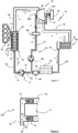
figure 1 qui illustre un circuit fermé fonctionnant selon un cycle de Rankine de l'art antérieur avec le dispositif de lubrification selon l'invention et - la
figure 2 qui montre un détail d'un des paliers de la turbine du circuit fermé de lafigure 1 . - Sur la
figure1 , le circuit fermé à cycle de Rankine 10 est avantageusement de type ORC (Organic Rankine Cycle) qui utilise un fluide organique ou un mélange de fluides organiques, comme du butane, de l'éthanol, des hydrofluorocarbures, du dioxyde de carbone. - Il est bien entendu que le circuit fermé peut fonctionner avec un fluide non organique comme de l'ammoniac ou de l'eau.
- Ce circuit comprend une pompe de circulation et de compression 12 du fluide de travail, dénommée pompe dans la suite de la description, avec une entrée 14 du fluide de travail sous forme liquide et une sortie 16 de ce fluide de travail également sous forme liquide mais comprimé sous une pression élevée. Cette pompe est avantageusement entraînée en rotation par tous moyens; comme un moteur électrique (non représenté).
- Ce circuit comporte aussi un échangeur de chaleur 18, dénommé évaporateur, traversé par le fluide de travail comprimé entre une entrée 20 de ce fluide liquide et une sortie 22 au travers de laquelle le fluide de travail ressort de cet évaporateur sous forme de vapeur comprimée. Cet évaporateur est parcouru par une source chaude 24 sous forme liquide ou gazeuse. Cette source chaude peut provenir des gaz d'échappement circulant dans la ligne d'échappement 26 d'un moteur à combustion interne 28, du fluide de refroidissement d'un moteur à combustion interne, du fluide de refroidissement d'un four industriel, ou du fluide caloporteur chauffé dans des installations thermiques ou par un bruleur.
- Ce circuit comporte également une machine de détente 30 recevant par son entrée 32 le fluide de travail sous forme de vapeur comprimée à haute pression, ce fluide ressortant par la sortie 34 de cette machine sous forme de vapeur détendue à basse pression.
- Avantageusement, cette machine de détente est sous la forme d'une turbine de détente dont l'arbre du rotor est placé sur deux paliers 36a et 36b et qui est entraîné en rotation par le fluide de travail sous forme de vapeur en commandant en rotation un arbre de liaison 37. De manière préférentielle, cet arbre permet de transmettre l'énergie récupérée à tout dispositif transformateur, comme par exemple une génératrice électrique 38.
- Le circuit comporte encore un échangeur de refroidissement 40, ou condenseur, avec une entrée 42 pour la vapeur basse pression détendue et une sortie 44 pour le fluide de travail transformé sous forme liquide après son passage dans ce condenseur. Ce condenseur est balayé par une source froide, généralement un flux d'air froid (Flèche F) généralement à température ambiante, de manière à refroidir la vapeur détendue pour qu'elle se condense et se transforme en un liquide. Bien entendu, toute autre source froide de refroidissement, comme de l'eau, peut être utilisée pour assurer la condensation de la vapeur.
- Ce circuit comporte également un réservoir fermé 46 qui permet de conserver le fluide de travail à l'état liquide et, de manière préférentielle, un filtre 48, comme un filtre à cartouche, pour filtrer le fluide de travail sortant du réservoir avant son introduction dans la pompe.
- Les différents éléments du circuit sont reliés entre eux par des conduites de circulation de fluide 50, 52, 54, 56, 58, 60 permettant de relier successivement la pompe avec l'évaporateur (conduite d'évaporateur 50), l'évaporateur avec la turbine (conduite de turbine 52), cette turbine avec le condenseur (conduite de condenseur 54), le condenseur avec le réservoir (conduite de réservoir 56), le réservoir au filtre (conduite de filtre 58) et le filtre à la pompe (conduite de pompe 60) pour que le fluide de travail circule selon le sens indiqué par les flèches A.
- Comme mieux visible sur la
figure 1 , le circuit fermé comprend un circuit de lubrification 62 utilisant le fluide qui y circule pour lubrifier au moins un palier recevant un arbre rotatif d'un élément du circuit fermé et plus particulièrement les paliers 36a, 36b de la turbine 30. - Bien entendu et cela sans sortir du cadre de l'invention, ce circuit de lubrification peut être utilisé pour lubrifier les paliers de tout autre élément tournant du circuit fermé, comme la pompe 12.
- Ce circuit de lubrification comprend une conduite de lubrification 64 qui prend naissance sur une des conduites situées entre le réservoir 46 et l'évaporateur 18 et qui aboutit aux paliers 36a, 36b de la turbine 30.
- Comme illustré à titre d'exemple sur la
figure 1 , cette conduite de lubrification prend naissance sur la conduite de pompe 60 entre le filtre et la pompe 12. - Cette conduite porte dans le sens de circulation selon la flèche A', une pompe de circulation 68, ou pompe de lubrification, permettant de faire circuler ce fluide dans la conduite et des moyens de sous-refroidissement 66 du fluide circulant dans la conduite de lubrification.
- Avantageusement, les moyens de refroidissement comprennent un dispositif à effet Peltier alimenté électriquement.
- La conduite porte également, entre la pompe 68 et les paliers, un capteur de température T et un capteur de pression P du fluide circulant dans cette conduite.
- Pour assurer la lubrification des paliers 36a et 36b, le fluide caloporteur, qui est filtré par le filtre 48 après sa sortie du réservoir 46 et qui est en phase liquide, est en partie dévié dans la conduite de lubrification pour y circuler sous l'impulsion de la pompe de lubrification 68. Cette pompe permet également de réguler le débit de fluide destiné à la lubrification des paliers.
- Lors de cette circulation, ce fluide est sous-refroidi par le dispositif à effet Peltier avant d'être introduit dans les paliers 36a et 36b.
- Outre le fait que le dispositif de sous-refroidissement permet, si nécessaire, de réguler la température du fluide destiné à la lubrification grâce aux capteurs, il a le rôle essentiel de retarder le passage à l'état gazeux du fluide après qu'il ait été injecté, à l'état liquide, dans les paliers.
- Avantageusement, la pompe de circulation 68 destinée à la lubrification des paliers et le dispositif à effet Peltier sont mis en route avant la mise en route de la pompe principale 12 du circuit fermé de manière à assurer la lubrification de la turbine avant sa mise en rotation.
- Par cela, la fonction lubrifiante des paliers est mieux assurée.
- Bien entendu et cela sans sortir du cadre de l'invention, il peut être envisagé de se dispenser de placer une pompe de circulation dans la conduite de lubrification et de se servir de la pompe 12 pour faire circuler le fluide dans cette conduite.
- Pour cela, cette conduite prend naissance en aval de la pompe 12, en considérant le sens de circulation A du fluide, et aboutit aux paliers 36a, 36b de la turbine 30.
- Avantageusement, la conduite porte un régulateur et/ou un limiteur de pression et/ou de débit de manière à contrôler la quantité de fluide qui arrive aux paliers.
- A titre d'exemple, comme illustré à la
figure 2 , l'arbre 70 de la turbine est porté par un roulement à billes 72 logé entre cet arbre et l'enveloppe fermée 74 du palier 36a. Cette enveloppe comporte également une admission 76 du fluide sous-refroidi par la conduite 64. - Comme mieux visible sur cette figure, un diffuseur circonférentiel 77 du fluide est placé entre l'admission et le roulement à billes.
- Ce diffuseur est ici une entretoise 78 munie de plusieurs points d'injection 80 répartis circonférentiellement de manière régulière.
- Ainsi, le fluide est mieux réparti sur toute la circonférence du roulement et la lubrification est plus homogène et plus efficace.
Claims (17)
- Dispositif de lubrification d'au moins un palier recevant un arbre rotatif d'un élément d'un circuit fermé (10) fonctionnant selon un cycle de Rankine, ledit circuit comprenant une pompe de compression/circulation (12) d'un fluide de travail sous forme liquide, un échangeur de chaleur (18) balayé par une source chaude (24) pour l'évaporation dudit fluide, des moyens de détente (30) du fluide sous forme vapeur, un échangeur de refroidissement (40) balayé par une source froide (F) pour la condensation du fluide de travail, un réservoir de fluide de travail (46), des conduites de circulation du fluide de travail (50, 52, 54, 56, 58, 60) et un circuit de lubrification (62) pour lubrifier ledit palier, caractérisé en ce que le circuit de lubrification comporte une conduite de lubrification (64) raccordée au circuit fermé (10) et comprenant des moyens de sous-refroidissement (66) du fluide circulant dans ladite conduite de lubrification, ladite conduite de lubrification (64) dérivant une partie du fluide de travail du circuit fermé vers ledit palier.
- Dispositif de lubrification selon la revendication 1, caractérisé en ce que la conduite de lubrification (64) prend naissance sur une des conduites (50, 58, 60) situées entre le réservoir (46) et l'échangeur de chaleur (18).
- Dispositif de lubrification selon la revendication 1 ou 2, caractérisé en ce que la conduite de lubrification (64) porte un régulateur et/ou un limiteur de pression et/ou de débit.
- Dispositif de lubrification selon la revendication 1 ou 2, caractérisé en ce que la conduite de lubrification (64) prend naissance sur la conduite (60, 58) en amont de la pompe de compression/circulation (12).
- Dispositif de lubrification selon l'une des revendications précédentes, caractérisé en ce que la conduite de lubrification (64) comprend une pompe de circulation (68).
- Dispositif de lubrification selon l'une des revendications précédentes, caractérisé en ce que la conduite de lubrification (64) comprend un capteur de température.
- Dispositif de lubrification selon l'une des revendications précédentes, caractérisé en ce que la conduite de lubrification (64) comprend un capteur de pression.
- Dispositif de lubrification selon l'une des revendications précédentes, caractérisé en ce que les moyens de sous-refroidissement (66) comprennent un dispositif à effet Peltier.
- Dispositif de lubrification selon l'une des revendications précédentes, caractérisé en ce que le palier comprend un diffuseur circonférentiel (77) du fluide de travail.
- Dispositif de lubrification selon la revendication 9, caractérisé en ce que le diffuseur comprend une entretoise (78) munie de points d'injection (80) régulièrement repartis circonférentiellement.
- Dispositif de lubrification selon l'une des revendications précédentes, caractérisé en ce que le fluide de travail est un fluide organique ou des mélanges de fluides organiques.
- Dispositif de lubrification selon l'une des revendications précédentes, caractérisé en ce que les moyens de détente comprennent une turbine (30) et en ce que le palier recevant l'arbre rotatif est le palier de la turbine.
- Procédé de lubrification d'au moins un palier recevant un arbre rotatif d'un élément d'un circuit fermé fonctionnant selon un cycle de Rankine, ledit circuit comprenant une pompe de compression/circulation (12) d'un fluide de travail sous forme liquide, un échangeur de chaleur (18) balayé par une source chaude (24) pour l'évaporation dudit fluide, des moyens de détente (30) du fluide sous forme vapeur, un échangeur de refroidissement (42) balayé par une source froide (F) pour la condensation du fluide de travail, un réservoir de fluide de travail (48), des conduites de circulation du fluide de travail (50, 52, 54 ,56, 58, 60), et un circuit de lubrification (62) pour lubrifier ledit palier, caractérisé en ce qu'on dérive dans une conduite de lubrification (64) une partie du fluide de travail du circuit fermé vers le palier et on sous-refroidit cette partie de fluide avant son admission dans ledit palier.
- Procédé de lubrification selon la revendication 13, caractérisé en ce qu'on régule et/ou limite la pression et/ou le débit du fluide pour contrôler la quantité de fluide admis dans le palier.
- Procédé de lubrification selon la revendication 13 ou 14, caractérisé en ce qu'on met en route une pompe de circulation (68) placée sur la conduite de pour la lubrification des paliers et on actionne les moyens de sous-refroidissement (66) avant la mise en route de la pompe de compression/circulation de manière à assurer la lubrification dudit palier.
- Procédé de lubrification selon l'une des revendications 13 à 15, caractérisé en ce qu'on repartit le fluide sur toute la circonférence du palier.
- Circuit fermé (10) fonctionnant selon un cycle de Rankine, caractérisé en ce qu'il comprend le dispositif de lubrification selon l'une des revendications 1 à 12 ou en ce qu'il utilise le procédé selon l'une des revendications 13 à 16.
Priority Applications (1)
| Application Number | Priority Date | Filing Date | Title |
|---|---|---|---|
| PL16766008T PL3359794T3 (pl) | 2015-10-09 | 2016-09-15 | Urządzenie do smarowania łożyska przyjmującego obracający się wał elementu obiegu zamkniętego działającego zgodnie z cyklem rankine’a i sposób stosujący takie urządzenie |
Applications Claiming Priority (2)
| Application Number | Priority Date | Filing Date | Title |
|---|---|---|---|
| FR1559607A FR3042216B1 (fr) | 2015-10-09 | 2015-10-09 | Dispositif de lubrification d'un palier recevant un arbre rotatif d'un element d'un circuit ferme fonctionnant selon un cycle de rankine et procede utilisant un tel dispositif. |
| PCT/EP2016/071840 WO2017060055A1 (fr) | 2015-10-09 | 2016-09-15 | Dispositif de lubrification d'un palier recevant un arbre rotatif d'un élément d'un circuit fermé fonctionnant selon un cycle de rankine et procédé utilisant un tel dispositif |
Publications (2)
| Publication Number | Publication Date |
|---|---|
| EP3359794A1 EP3359794A1 (fr) | 2018-08-15 |
| EP3359794B1 true EP3359794B1 (fr) | 2021-12-15 |
Family
ID=55072895
Family Applications (1)
| Application Number | Title | Priority Date | Filing Date |
|---|---|---|---|
| EP16766008.3A Active EP3359794B1 (fr) | 2015-10-09 | 2016-09-15 | Dispositif de lubrification d'un palier recevant un arbre rotatif d'un élément d'un circuit fermé fonctionnant selon un cycle de rankine et procédé utilisant un tel dispositif |
Country Status (8)
| Country | Link |
|---|---|
| EP (1) | EP3359794B1 (fr) |
| JP (3) | JP2018534485A (fr) |
| KR (1) | KR20180063882A (fr) |
| CN (1) | CN108138695A (fr) |
| ES (1) | ES2906130T3 (fr) |
| FR (1) | FR3042216B1 (fr) |
| PL (1) | PL3359794T3 (fr) |
| WO (1) | WO2017060055A1 (fr) |
Families Citing this family (3)
| Publication number | Priority date | Publication date | Assignee | Title |
|---|---|---|---|---|
| FR3077122B1 (fr) * | 2018-01-19 | 2019-12-20 | Psa Automobiles Sa | Systeme a cycle thermodynamique de rankine integre a une boucle de climatisation pour vehicule automobile |
| CN111894692B (zh) * | 2020-08-03 | 2022-11-25 | 河北亚迎科技有限公司 | 一种工业余热二次利用监控系统 |
| US20220199270A1 (en) * | 2020-12-22 | 2022-06-23 | Ge-Hitachi Nuclear Energy Americas Llc | Coolant cleanup systems with direct mixing and methods of using the same |
Family Cites Families (8)
| Publication number | Priority date | Publication date | Assignee | Title |
|---|---|---|---|---|
| JP4071552B2 (ja) * | 2001-07-10 | 2008-04-02 | 本田技研工業株式会社 | ランキンサイクル装置 |
| JP2004278570A (ja) * | 2003-03-13 | 2004-10-07 | Koyo Seiko Co Ltd | 軸受装置の冷却機構 |
| JP4286062B2 (ja) * | 2003-05-29 | 2009-06-24 | 株式会社荏原製作所 | 発電装置および発電方法 |
| FR2884555A1 (fr) | 2005-04-13 | 2006-10-20 | Peugeot Citroen Automobiles Sa | Dispositif de recuperation d'energie d'un moteur a combustion interne |
| GB0511864D0 (en) * | 2005-06-10 | 2005-07-20 | Univ City | Expander lubrication in vapour power systems |
| JP2007327359A (ja) * | 2006-06-06 | 2007-12-20 | Ebara Corp | 排熱発電装置、及びその運転方法 |
| DE102007041944B3 (de) * | 2007-09-04 | 2009-02-19 | Gesellschaft für Motoren und Kraftanlagen mbH | Vorrichtung zur Energieumwandlung, Kraft-Wärme-Kopplungsanlage mit einer derartigen Vorrichtung und Verfahren zum Betreiben einer ORC-Anlage |
| EP2746543B1 (fr) * | 2012-12-21 | 2016-09-28 | Orcan Energy AG | Lubrification de machines d'expansion |
-
2015
- 2015-10-09 FR FR1559607A patent/FR3042216B1/fr active Active
-
2016
- 2016-09-15 PL PL16766008T patent/PL3359794T3/pl unknown
- 2016-09-15 ES ES16766008T patent/ES2906130T3/es active Active
- 2016-09-15 CN CN201680057467.7A patent/CN108138695A/zh active Pending
- 2016-09-15 KR KR1020187009340A patent/KR20180063882A/ko not_active Application Discontinuation
- 2016-09-15 WO PCT/EP2016/071840 patent/WO2017060055A1/fr active Application Filing
- 2016-09-15 EP EP16766008.3A patent/EP3359794B1/fr active Active
- 2016-09-15 JP JP2018537717A patent/JP2018534485A/ja active Pending
-
2021
- 2021-05-25 JP JP2021087436A patent/JP2021156292A/ja active Pending
-
2023
- 2023-01-13 JP JP2023003460A patent/JP7402358B2/ja active Active
Also Published As
| Publication number | Publication date |
|---|---|
| PL3359794T3 (pl) | 2022-04-04 |
| FR3042216A1 (fr) | 2017-04-14 |
| ES2906130T3 (es) | 2022-04-13 |
| JP2023052373A (ja) | 2023-04-11 |
| JP7402358B2 (ja) | 2023-12-20 |
| EP3359794A1 (fr) | 2018-08-15 |
| KR20180063882A (ko) | 2018-06-12 |
| CN108138695A (zh) | 2018-06-08 |
| JP2018534485A (ja) | 2018-11-22 |
| FR3042216B1 (fr) | 2019-06-28 |
| WO2017060055A1 (fr) | 2017-04-13 |
| JP2021156292A (ja) | 2021-10-07 |
Similar Documents
| Publication | Publication Date | Title |
|---|---|---|
| EP2933444A1 (fr) | Dispositif de contrôle d'un circuit fermé fonctionnant selon un cycle de Rankine et procédé utilisant un tel dispositif. | |
| EP2805032B1 (fr) | Dispositif de contrôle d'un fluide de travail dans un circuit fermé fonctionnant selon un cycle de rankine et procédé utilisant un tel dispositif | |
| EP2360355B1 (fr) | Dispositif de contrôle d'un fluide de travail à bas point de congélation circulant dans un circuit fermé fonctionnant selon un cycle de Rankine et procédé utilisant un tel dispositif | |
| JP7402358B2 (ja) | ランキンサイクルに従って動作する閉回路の一部材の回転軸を受け入れる軸受を潤滑する装置およびそのような装置を使用する方法 | |
| EP2381072B1 (fr) | Circuit fermé fonctionnant selon un cycle de rankine et procede utilisant un tel circuit | |
| EP3500734B1 (fr) | Circuit fermé fonctionnant selon un cycle de rankine avec un dispositif pour l'arrèt d'urgence du circuit et procédé utilisant un tel circuit | |
| FR3004487A1 (fr) | Procede de controle du fonctionnement d'un circuit ferme fonctionnant selon un cycle de rankine et circuit utilisant un tel procede. | |
| FR2503335A1 (fr) | Installation pour utiliser la chaleur perdue de faible potentiel d'une station de compression pour pipelines de gaz | |
| EP3363101B1 (fr) | Dispositif d'isolation thermique entre une turbine dont la roue est entraînée en rotation par un fluide chaud et une génératrice électrique avec un rotor accouplé à cette roue, notamment pour une turbogénératrice | |
| EP3472439B1 (fr) | Procédé de détection et d'extraction de fluide gazeux contenu dans un circuit fermé fonctionnant selon un cycle de rankine et dispositif utilisant un tel procédé | |
| EP3724459A1 (fr) | Ensemble de turbopompe electrifiee pour un circuit ferme, en particulier de type a cycle de rankine, comportant un refroidissement integre | |
| FR3065254B1 (fr) | Ensemble de turbopompe pour un circuit ferme, en particulier de type a cycle de rankine, associe a un moteur a combustion interne, notamment pour vehicule automobile | |
| WO2016128527A1 (fr) | Système thermodynamique | |
| FR3045726A1 (fr) | Dispositifs et procede d'extraction et de valorisation de l'energie de detente d'un gaz sous pression non chauffe | |
| FR2981144A1 (fr) | Turbo pompe a chaleur. | |
| WO2017092922A1 (fr) | Système thermodynamique | |
| FR3050238A1 (fr) | Systeme de gestion d'air d'admission pour un moteur thermique de vehicule automobile | |
| FR3032520A1 (fr) | Systeme thermodynamique |
Legal Events
| Date | Code | Title | Description |
|---|---|---|---|
| STAA | Information on the status of an ep patent application or granted ep patent |
Free format text: STATUS: THE INTERNATIONAL PUBLICATION HAS BEEN MADE |
|
| PUAI | Public reference made under article 153(3) epc to a published international application that has entered the european phase |
Free format text: ORIGINAL CODE: 0009012 |
|
| STAA | Information on the status of an ep patent application or granted ep patent |
Free format text: STATUS: REQUEST FOR EXAMINATION WAS MADE |
|
| 17P | Request for examination filed |
Effective date: 20180509 |
|
| AK | Designated contracting states |
Kind code of ref document: A1 Designated state(s): AL AT BE BG CH CY CZ DE DK EE ES FI FR GB GR HR HU IE IS IT LI LT LU LV MC MK MT NL NO PL PT RO RS SE SI SK SM TR |
|
| AX | Request for extension of the european patent |
Extension state: BA ME |
|
| DAV | Request for validation of the european patent (deleted) | ||
| DAX | Request for extension of the european patent (deleted) | ||
| GRAP | Despatch of communication of intention to grant a patent |
Free format text: ORIGINAL CODE: EPIDOSNIGR1 |
|
| STAA | Information on the status of an ep patent application or granted ep patent |
Free format text: STATUS: GRANT OF PATENT IS INTENDED |
|
| INTG | Intention to grant announced |
Effective date: 20210810 |
|
| GRAS | Grant fee paid |
Free format text: ORIGINAL CODE: EPIDOSNIGR3 |
|
| GRAA | (expected) grant |
Free format text: ORIGINAL CODE: 0009210 |
|
| STAA | Information on the status of an ep patent application or granted ep patent |
Free format text: STATUS: THE PATENT HAS BEEN GRANTED |
|
| AK | Designated contracting states |
Kind code of ref document: B1 Designated state(s): AL AT BE BG CH CY CZ DE DK EE ES FI FR GB GR HR HU IE IS IT LI LT LU LV MC MK MT NL NO PL PT RO RS SE SI SK SM TR |
|
| REG | Reference to a national code |
Ref country code: GB Ref legal event code: FG4D Free format text: NOT ENGLISH Ref country code: CH Ref legal event code: EP |
|
| REG | Reference to a national code |
Ref country code: IE Ref legal event code: FG4D Free format text: LANGUAGE OF EP DOCUMENT: FRENCH Ref country code: DE Ref legal event code: R096 Ref document number: 602016067402 Country of ref document: DE |
|
| REG | Reference to a national code |
Ref country code: AT Ref legal event code: REF Ref document number: 1455661 Country of ref document: AT Kind code of ref document: T Effective date: 20220115 |
|
| REG | Reference to a national code |
Ref country code: SE Ref legal event code: TRGR |
|
| REG | Reference to a national code |
Ref country code: LT Ref legal event code: MG9D |
|
| REG | Reference to a national code |
Ref country code: ES Ref legal event code: FG2A Ref document number: 2906130 Country of ref document: ES Kind code of ref document: T3 Effective date: 20220413 |
|
| REG | Reference to a national code |
Ref country code: NL Ref legal event code: MP Effective date: 20211215 |
|
| PG25 | Lapsed in a contracting state [announced via postgrant information from national office to epo] |
Ref country code: RS Free format text: LAPSE BECAUSE OF FAILURE TO SUBMIT A TRANSLATION OF THE DESCRIPTION OR TO PAY THE FEE WITHIN THE PRESCRIBED TIME-LIMIT Effective date: 20211215 Ref country code: LT Free format text: LAPSE BECAUSE OF FAILURE TO SUBMIT A TRANSLATION OF THE DESCRIPTION OR TO PAY THE FEE WITHIN THE PRESCRIBED TIME-LIMIT Effective date: 20211215 Ref country code: FI Free format text: LAPSE BECAUSE OF FAILURE TO SUBMIT A TRANSLATION OF THE DESCRIPTION OR TO PAY THE FEE WITHIN THE PRESCRIBED TIME-LIMIT Effective date: 20211215 Ref country code: BG Free format text: LAPSE BECAUSE OF FAILURE TO SUBMIT A TRANSLATION OF THE DESCRIPTION OR TO PAY THE FEE WITHIN THE PRESCRIBED TIME-LIMIT Effective date: 20220315 |
|
| REG | Reference to a national code |
Ref country code: AT Ref legal event code: MK05 Ref document number: 1455661 Country of ref document: AT Kind code of ref document: T Effective date: 20211215 |
|
| PG25 | Lapsed in a contracting state [announced via postgrant information from national office to epo] |
Ref country code: NO Free format text: LAPSE BECAUSE OF FAILURE TO SUBMIT A TRANSLATION OF THE DESCRIPTION OR TO PAY THE FEE WITHIN THE PRESCRIBED TIME-LIMIT Effective date: 20220315 Ref country code: LV Free format text: LAPSE BECAUSE OF FAILURE TO SUBMIT A TRANSLATION OF THE DESCRIPTION OR TO PAY THE FEE WITHIN THE PRESCRIBED TIME-LIMIT Effective date: 20211215 Ref country code: HR Free format text: LAPSE BECAUSE OF FAILURE TO SUBMIT A TRANSLATION OF THE DESCRIPTION OR TO PAY THE FEE WITHIN THE PRESCRIBED TIME-LIMIT Effective date: 20211215 Ref country code: GR Free format text: LAPSE BECAUSE OF FAILURE TO SUBMIT A TRANSLATION OF THE DESCRIPTION OR TO PAY THE FEE WITHIN THE PRESCRIBED TIME-LIMIT Effective date: 20220316 |
|
| PG25 | Lapsed in a contracting state [announced via postgrant information from national office to epo] |
Ref country code: NL Free format text: LAPSE BECAUSE OF FAILURE TO SUBMIT A TRANSLATION OF THE DESCRIPTION OR TO PAY THE FEE WITHIN THE PRESCRIBED TIME-LIMIT Effective date: 20211215 |
|
| PG25 | Lapsed in a contracting state [announced via postgrant information from national office to epo] |
Ref country code: SM Free format text: LAPSE BECAUSE OF FAILURE TO SUBMIT A TRANSLATION OF THE DESCRIPTION OR TO PAY THE FEE WITHIN THE PRESCRIBED TIME-LIMIT Effective date: 20211215 Ref country code: SK Free format text: LAPSE BECAUSE OF FAILURE TO SUBMIT A TRANSLATION OF THE DESCRIPTION OR TO PAY THE FEE WITHIN THE PRESCRIBED TIME-LIMIT Effective date: 20211215 Ref country code: RO Free format text: LAPSE BECAUSE OF FAILURE TO SUBMIT A TRANSLATION OF THE DESCRIPTION OR TO PAY THE FEE WITHIN THE PRESCRIBED TIME-LIMIT Effective date: 20211215 Ref country code: PT Free format text: LAPSE BECAUSE OF FAILURE TO SUBMIT A TRANSLATION OF THE DESCRIPTION OR TO PAY THE FEE WITHIN THE PRESCRIBED TIME-LIMIT Effective date: 20220418 Ref country code: EE Free format text: LAPSE BECAUSE OF FAILURE TO SUBMIT A TRANSLATION OF THE DESCRIPTION OR TO PAY THE FEE WITHIN THE PRESCRIBED TIME-LIMIT Effective date: 20211215 Ref country code: CZ Free format text: LAPSE BECAUSE OF FAILURE TO SUBMIT A TRANSLATION OF THE DESCRIPTION OR TO PAY THE FEE WITHIN THE PRESCRIBED TIME-LIMIT Effective date: 20211215 |
|
| PG25 | Lapsed in a contracting state [announced via postgrant information from national office to epo] |
Ref country code: AT Free format text: LAPSE BECAUSE OF FAILURE TO SUBMIT A TRANSLATION OF THE DESCRIPTION OR TO PAY THE FEE WITHIN THE PRESCRIBED TIME-LIMIT Effective date: 20211215 |
|
| REG | Reference to a national code |
Ref country code: DE Ref legal event code: R097 Ref document number: 602016067402 Country of ref document: DE |
|
| PG25 | Lapsed in a contracting state [announced via postgrant information from national office to epo] |
Ref country code: IS Free format text: LAPSE BECAUSE OF FAILURE TO SUBMIT A TRANSLATION OF THE DESCRIPTION OR TO PAY THE FEE WITHIN THE PRESCRIBED TIME-LIMIT Effective date: 20220415 |
|
| PLBE | No opposition filed within time limit |
Free format text: ORIGINAL CODE: 0009261 |
|
| STAA | Information on the status of an ep patent application or granted ep patent |
Free format text: STATUS: NO OPPOSITION FILED WITHIN TIME LIMIT |
|
| PG25 | Lapsed in a contracting state [announced via postgrant information from national office to epo] |
Ref country code: DK Free format text: LAPSE BECAUSE OF FAILURE TO SUBMIT A TRANSLATION OF THE DESCRIPTION OR TO PAY THE FEE WITHIN THE PRESCRIBED TIME-LIMIT Effective date: 20211215 Ref country code: AL Free format text: LAPSE BECAUSE OF FAILURE TO SUBMIT A TRANSLATION OF THE DESCRIPTION OR TO PAY THE FEE WITHIN THE PRESCRIBED TIME-LIMIT Effective date: 20211215 |
|
| 26N | No opposition filed |
Effective date: 20220916 |
|
| PG25 | Lapsed in a contracting state [announced via postgrant information from national office to epo] |
Ref country code: SI Free format text: LAPSE BECAUSE OF FAILURE TO SUBMIT A TRANSLATION OF THE DESCRIPTION OR TO PAY THE FEE WITHIN THE PRESCRIBED TIME-LIMIT Effective date: 20211215 |
|
| PG25 | Lapsed in a contracting state [announced via postgrant information from national office to epo] |
Ref country code: MC Free format text: LAPSE BECAUSE OF FAILURE TO SUBMIT A TRANSLATION OF THE DESCRIPTION OR TO PAY THE FEE WITHIN THE PRESCRIBED TIME-LIMIT Effective date: 20211215 |
|
| REG | Reference to a national code |
Ref country code: CH Ref legal event code: PL |
|
| REG | Reference to a national code |
Ref country code: BE Ref legal event code: MM Effective date: 20220930 |
|
| PG25 | Lapsed in a contracting state [announced via postgrant information from national office to epo] |
Ref country code: LU Free format text: LAPSE BECAUSE OF NON-PAYMENT OF DUE FEES Effective date: 20220915 |
|
| PG25 | Lapsed in a contracting state [announced via postgrant information from national office to epo] |
Ref country code: LI Free format text: LAPSE BECAUSE OF NON-PAYMENT OF DUE FEES Effective date: 20220930 Ref country code: CH Free format text: LAPSE BECAUSE OF NON-PAYMENT OF DUE FEES Effective date: 20220930 |
|
| PG25 | Lapsed in a contracting state [announced via postgrant information from national office to epo] |
Ref country code: BE Free format text: LAPSE BECAUSE OF NON-PAYMENT OF DUE FEES Effective date: 20220930 |
|
| PGFP | Annual fee paid to national office [announced via postgrant information from national office to epo] |
Ref country code: IT Payment date: 20230920 Year of fee payment: 8 Ref country code: IE Payment date: 20230919 Year of fee payment: 8 Ref country code: GB Payment date: 20230926 Year of fee payment: 8 |
|
| PGFP | Annual fee paid to national office [announced via postgrant information from national office to epo] |
Ref country code: SE Payment date: 20230926 Year of fee payment: 8 Ref country code: PL Payment date: 20230904 Year of fee payment: 8 Ref country code: FR Payment date: 20230926 Year of fee payment: 8 Ref country code: DE Payment date: 20230928 Year of fee payment: 8 |
|
| PGFP | Annual fee paid to national office [announced via postgrant information from national office to epo] |
Ref country code: ES Payment date: 20231017 Year of fee payment: 8 |
|
| PG25 | Lapsed in a contracting state [announced via postgrant information from national office to epo] |
Ref country code: HU Free format text: LAPSE BECAUSE OF FAILURE TO SUBMIT A TRANSLATION OF THE DESCRIPTION OR TO PAY THE FEE WITHIN THE PRESCRIBED TIME-LIMIT; INVALID AB INITIO Effective date: 20160915 |
|
| PG25 | Lapsed in a contracting state [announced via postgrant information from national office to epo] |
Ref country code: CY Free format text: LAPSE BECAUSE OF FAILURE TO SUBMIT A TRANSLATION OF THE DESCRIPTION OR TO PAY THE FEE WITHIN THE PRESCRIBED TIME-LIMIT Effective date: 20211215 |