EP3359366B1 - Blasformanordnung - Google Patents
Blasformanordnung Download PDFInfo
- Publication number
- EP3359366B1 EP3359366B1 EP16854160.5A EP16854160A EP3359366B1 EP 3359366 B1 EP3359366 B1 EP 3359366B1 EP 16854160 A EP16854160 A EP 16854160A EP 3359366 B1 EP3359366 B1 EP 3359366B1
- Authority
- EP
- European Patent Office
- Prior art keywords
- neck
- mold
- neck insert
- mold component
- mold assembly
- Prior art date
- Legal status (The legal status is an assumption and is not a legal conclusion. Google has not performed a legal analysis and makes no representation as to the accuracy of the status listed.)
- Active
Links
Images



Classifications
-
- B—PERFORMING OPERATIONS; TRANSPORTING
- B29—WORKING OF PLASTICS; WORKING OF SUBSTANCES IN A PLASTIC STATE IN GENERAL
- B29C—SHAPING OR JOINING OF PLASTICS; SHAPING OF MATERIAL IN A PLASTIC STATE, NOT OTHERWISE PROVIDED FOR; AFTER-TREATMENT OF THE SHAPED PRODUCTS, e.g. REPAIRING
- B29C49/00—Blow-moulding, i.e. blowing a preform or parison to a desired shape within a mould; Apparatus therefor
- B29C49/42—Component parts, details or accessories; Auxiliary operations
- B29C49/48—Moulds
-
- B—PERFORMING OPERATIONS; TRANSPORTING
- B29—WORKING OF PLASTICS; WORKING OF SUBSTANCES IN A PLASTIC STATE IN GENERAL
- B29C—SHAPING OR JOINING OF PLASTICS; SHAPING OF MATERIAL IN A PLASTIC STATE, NOT OTHERWISE PROVIDED FOR; AFTER-TREATMENT OF THE SHAPED PRODUCTS, e.g. REPAIRING
- B29C49/00—Blow-moulding, i.e. blowing a preform or parison to a desired shape within a mould; Apparatus therefor
- B29C49/02—Combined blow-moulding and manufacture of the preform or the parison
- B29C49/04—Extrusion blow-moulding
- B29C49/04102—Extrusion blow-moulding extruding the material continuously
-
- B—PERFORMING OPERATIONS; TRANSPORTING
- B29—WORKING OF PLASTICS; WORKING OF SUBSTANCES IN A PLASTIC STATE IN GENERAL
- B29C—SHAPING OR JOINING OF PLASTICS; SHAPING OF MATERIAL IN A PLASTIC STATE, NOT OTHERWISE PROVIDED FOR; AFTER-TREATMENT OF THE SHAPED PRODUCTS, e.g. REPAIRING
- B29C49/00—Blow-moulding, i.e. blowing a preform or parison to a desired shape within a mould; Apparatus therefor
- B29C49/42—Component parts, details or accessories; Auxiliary operations
- B29C49/48—Moulds
- B29C49/4802—Moulds with means for locally compressing part(s) of the parison in the main blowing cavity
- B29C49/4817—Moulds with means for locally compressing part(s) of the parison in the main blowing cavity with means for closing off parison ends
-
- B—PERFORMING OPERATIONS; TRANSPORTING
- B29—WORKING OF PLASTICS; WORKING OF SUBSTANCES IN A PLASTIC STATE IN GENERAL
- B29C—SHAPING OR JOINING OF PLASTICS; SHAPING OF MATERIAL IN A PLASTIC STATE, NOT OTHERWISE PROVIDED FOR; AFTER-TREATMENT OF THE SHAPED PRODUCTS, e.g. REPAIRING
- B29C49/00—Blow-moulding, i.e. blowing a preform or parison to a desired shape within a mould; Apparatus therefor
- B29C49/42—Component parts, details or accessories; Auxiliary operations
- B29C49/48—Moulds
- B29C49/50—Moulds having cutting or deflashing means
-
- B—PERFORMING OPERATIONS; TRANSPORTING
- B29—WORKING OF PLASTICS; WORKING OF SUBSTANCES IN A PLASTIC STATE IN GENERAL
- B29C—SHAPING OR JOINING OF PLASTICS; SHAPING OF MATERIAL IN A PLASTIC STATE, NOT OTHERWISE PROVIDED FOR; AFTER-TREATMENT OF THE SHAPED PRODUCTS, e.g. REPAIRING
- B29C49/00—Blow-moulding, i.e. blowing a preform or parison to a desired shape within a mould; Apparatus therefor
- B29C49/42—Component parts, details or accessories; Auxiliary operations
- B29C49/48—Moulds
- B29C2049/4856—Mounting, exchanging or centering moulds or parts thereof
- B29C2049/4858—Exchanging mould parts, e.g. for changing the mould size or geometry for making different products in the same mould
- B29C2049/4861—Neck portions of bottle producing moulds
-
- B—PERFORMING OPERATIONS; TRANSPORTING
- B29—WORKING OF PLASTICS; WORKING OF SUBSTANCES IN A PLASTIC STATE IN GENERAL
- B29C—SHAPING OR JOINING OF PLASTICS; SHAPING OF MATERIAL IN A PLASTIC STATE, NOT OTHERWISE PROVIDED FOR; AFTER-TREATMENT OF THE SHAPED PRODUCTS, e.g. REPAIRING
- B29C49/00—Blow-moulding, i.e. blowing a preform or parison to a desired shape within a mould; Apparatus therefor
- B29C49/42—Component parts, details or accessories; Auxiliary operations
- B29C49/56—Opening, closing or clamping means
- B29C2049/563—Clamping means
-
- B—PERFORMING OPERATIONS; TRANSPORTING
- B29—WORKING OF PLASTICS; WORKING OF SUBSTANCES IN A PLASTIC STATE IN GENERAL
- B29L—INDEXING SCHEME ASSOCIATED WITH SUBCLASS B29C, RELATING TO PARTICULAR ARTICLES
- B29L2031/00—Other particular articles
- B29L2031/712—Containers; Packaging elements or accessories, Packages
-
- B—PERFORMING OPERATIONS; TRANSPORTING
- B29—WORKING OF PLASTICS; WORKING OF SUBSTANCES IN A PLASTIC STATE IN GENERAL
- B29L—INDEXING SCHEME ASSOCIATED WITH SUBCLASS B29C, RELATING TO PARTICULAR ARTICLES
- B29L2031/00—Other particular articles
- B29L2031/712—Containers; Packaging elements or accessories, Packages
- B29L2031/7158—Bottles
-
- B—PERFORMING OPERATIONS; TRANSPORTING
- B29—WORKING OF PLASTICS; WORKING OF SUBSTANCES IN A PLASTIC STATE IN GENERAL
- B29L—INDEXING SCHEME ASSOCIATED WITH SUBCLASS B29C, RELATING TO PARTICULAR ARTICLES
- B29L2031/00—Other particular articles
- B29L2031/712—Containers; Packaging elements or accessories, Packages
- B29L2031/7172—Fuel tanks, jerry cans
Definitions
- This invention relates generally to blow molded containers.
- this invention relates to mold assemblies wherein the so-called “neck finish” (surface feature for engaging a container closure) is formed in the blow molding process.
- Blow molding is a cyclic process wherein a hollow tubular preform of material in a moldable condition is centered on the parting plane of a mold assembly, the mold assembly is closed around the preform, the preform is expanded so the exterior of the preform abuts molding surfaces defined by the closed mold assembly, the blow molded article is conditioned to be sufficiently rigid to retain its size and shape while unsupported, the mold assembly is opened and the blow molded article is removed.
- the moldable condition of the preform is achieved when the material of the preform is at an elevated temperature
- the rigid condition of the blow molded article is achieved when the temperature of the material has been reduced.
- a blow molding machine comprises a press for opening and closing the mold assembly and pressurizing apparatus for introducing a pressurized fluid (typically air) to expand the preform in the closed mold assembly.
- a pressurized fluid typically air
- One type of blow molding equipment produces blow molded containers from tubular extrusions produced by extruding equipment arranged relative a molding assembly to position one or more extrusions in the parting plane of the mold assembly.
- a substantially tubular extrusion extends below the lower end of a cavity defined by mating mold members and, with abutment of the mating mold members, the lower extremity of the extrusion is closed leaving the upper end of the extrusion open so as to create a blow moldable preform.
- Blow molding is commonly used for production of containers for transporting, storing and dispensing liquids
- the blow molded article comprises a body portion and a neck connecting the container body with a mouth opening for filling the container and dispensing the contents therefrom.
- the neck portion of the container comprises an exterior surface having one or more features, referred to herein as the "neck finish", for engaging a separable closure for covering the mouth opening.
- Known neck finish features include: (i) screw type threads for engaging mating threads on a shank of a closure; and, (ii) at least one protruding circumferential ring, such as a so-called "snap ring" for engaging compatible features in a shank of a closure to resist detachment of the closure from the neck finish.
- Mold assemblies for blow molding containers comprise mating mold components wherein molding surfaces open to the mating faces of the mold components define the exterior of the container.
- mold assemblies comprise replaceable insert components for forming the neck portion, wherein the neck insert mold components define the exterior surface of at least the neck finish.
- US 5 894 024A discloses a pinch-off neck assembly for use in a container blow mold system
- US 2007/087075 A1 shows blow molded containers wherein the so called bumper roll or transfer ring is formed in the blow molding process
- US 8 770 961 B1 and US 2014/017353 A1 relate to the fixation of a mold to a mold-carrier.
- each removable neck insert mold component comprises (i) a neck finish member for forming, at least in part, the exterior surface of the portion of the container that engages a removable container closure; (ii) a shear member for parting a tubular parison so as to define a preform below the shear member; and, the mold assembly comprises at least one manually operable retention device for retaining the neck insert mold component with a mating mold component of the blow mold assembly.
- the present invention provides a blow mold assembly for blow molding a container having a neck portion for engaging a removable container closure, the blow mold assembly comprising opposed mating mold components for forming the container wherein each mating mold component comprises a removable neck insert mold component for forming the container closure engaging features of the container neck and at least one manually operable retention device for retaining the neck insert mold component with a mating mold component of the blow mold assembly.
- each neck insert mold component comprises a shear member for parting the tubular parison to define the preform from the portion of the parison below the shear member, a neck finish member for forming the container closure engaging features on the preform and a plurality of pins for aligning the shear member with the neck finish member.
- each manually operable retention device comprises a toggle mechanism comprising a clamp arm for contacting a neck insert mold component and a lever arm, the clamp arm being rotated between a release position and a clamp position by operation of the lever arm and with the clamp arm in the clamp position, the toggle mechanism effective to resist forces acting on the clamp arm to rotate the clamp arm toward the release position.
- the manually operable retention devices are retained with the mating mold component when the neck insert mold component is removed or installed
- container 2 comprises a closed end at base 4 and a mouth opening 6 joined to hollow body 8 by neck 7.
- Neck 7 comprises neck finish 5 shown as a thread flight for engaging a closure (not shown) for covering mouth opening 6.
- bumper roll 9 is interposed between neck finish 5 and body 8 and serves to improve resistance to deformation of the body 8 in consequence of compressive forces applied vertically to neck 7 when the container is filled and/or a closure is applied.
- mold assembly 10 comprises opposed mating mold components 12 and 22 each referred to herein as a "mold half", “mating mold half” or “mating mold component”.
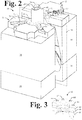
- mold components 12 and 22 are carried by a member of a molding machine press (not shown) for translating the mold components between open and closed positions relative to each other (the open position depicted in Fig.2 ). In the open position, mating mold components 12 and 22 are separated permitting admission of a so-called parison such as tubular extrusion 40 there between and removal of a molded article upon completion of a blow molding operation.
- tubular extrusion 40 is formed as a single continuous tubular extrusion and extends below the lowest molding surface of the cavity created with abutment of mating mold components 12 and 22.
- each mold half comprises a neck insert block such as neck insert blocks 20 and 21 for receiving a neck insert mold component such as neck insert mold components 42 and 43.
- Neck insert mold components 42 and 43 comprise molding surfaces that create closure retention surface features on the exterior of the neck of a container such as neck 7 of the container of Fig. 1 .
- each neck insert mold component is held in place in its associated neck insert block by clamping devices such as clamping mechanisms 70, 71, 72 and 73.
- Clamping mechanisms 70, 71, 72 and 73 are manually operable between closed (clamping) and open (release) conditions to allow neck insert mold components 42 and 43 to be removed from and installed in neck insert blocks 20 and 21, respectively.
- Fig. 2 illustrates the closed condition of manually operable clamping mechanisms 70, 71, 72 and 73.
- Fig. 3 illustrates details of a neck insert mold component such as neck insert mold component 42.
- each neck insert mold component comprises three molding elements: (i) neck insert "master" member 44 effective to seal the interior of parison 40 when a nozzle is inserted in the open end thereof; (ii) sheer member 46; and. (iii) neck finish member 48.
- Shear member 46 is effective to separate the neck 7 from parison 40 on closure of mold assembly 10.
- the portion of parison 40 between shear member 46 and mold base blocks 14 and 24 constitutes a blow moldable preform having a closed end formed by abutment of base blocks 14 and 24 and an open end at neck insert mold components 42 and 43.
- Neck finish member 48 is shown with molding surfaces for forming threads on the exterior of neck 7 as would be used to engage mating threads on the interior of a closure element (not shown). Movement of the neck insert members of neck insert components 42 and 43 relative to each other and relative to neck insert blocks 20 and 21, respectively, is prevented by alignment pins such as alignment pins 60, 62, 64 and 68 passing through the neck insert members and into the associated neck insert block such as neck insert block 20. As seen in Fig. 3 , recessed areas comprise the face ends of master member 44, shear member 46 and neck finish member 48 to allow room for the relatively large volume of material of parison 40 captured at the neck insert mold components when mating mold components 12 and 22 are brought into abutment.
- mating mold component 12 will be described with reference to Fig. 4 .
- neck insert mold component 42 has been removed and clamping mechanisms 70 and 72 are shown in their "open" or release condition.
- Step 36 in the face side of neck insert block 20 provides support surfaces for a neck insert mold component such as neck insert mold component 42.
- Through holes, such as through holes 36a, 36b, 36c and 36d receive the ends of alignment pins 60, 62, 64 and 68, respectively, that project below neck insert mold component 42.
- alignment pins 60, 62, 64 and 68 prevent horizontal translation and rotation of neck insert mold component 42 relative to neck insert block 20.
- Mold half 12 comprises molding surfaces defining portion 32 of the cavity created by abutment of mating mold components 12 and 22.
- cavity portion 32 comprises molding surfaces 34 that define the body of a container such as body 8 of the container of Fig. 1 ; and, molding surfaces 38 that define the base portion of a container such as base 4 of the container of Fig. 1 .
- mating mold component 12 comprises center section 16 comprising molding surfaces 34 and base block 14 comprising molding surfaces 38.
- Neck insert block 20 is attached to mold component 12 by fasteners (not shown).
- the corresponding sections of mating mold component 22 are center section 26, base block 24 and neck insert block 21.
- Mating mold component 22 comprises molding surfaces substantially mirroring molding surfaces 34 and 38 of mating mold component 12 and neck insert mold component 43 includes elements comprising features including molding surfaces substantially mirroring elements of neck insert mold component 42. With mating mold components 12 and 22 abutting, the molding surfaces of base blocks 14 and 24, center sections 16 and 26, and neck insert mold components 42 and 43 define a complete cavity of mold assembly 10.
- each neck insert mold component comprises a neck finish member, such as neck finish member 48, a shear member, such as shear member 46 and a master member, such as master member 44.
- Stacking and alignment of members of neck insert mold components such as neck insert mold component 42 shall be described with reference to Figs 5a and 5b .
- members of neck insert mold component 42 are shown spaced apart to reveal through holes of each component.
- through holes 44a, 44b, 44c and 44d of neck master component 44 comprise counter-bores and are shown with alignment pins 60, 62, 64 and 68 partially inserted therein.
- FIG. 5b illustrates a partial cross section of members of a neck insert mold component when in place in a neck insert block together with a partial cross section of a portion of parison 40.
- neck insert mold component members such as neck master member 44, shear member 46 and neck finish member 48 are stacked one atop the other and seated on step 36 of neck insert block 20.
- alignment pin 62 when seated in the counter-bores of through holes of neck master component 44, the alignment pins project into a through hole of neck insert block 20, such as through hole 36b, but do not extend through neck insert block 20. Alignment of members of neck insert mold component 42 to one another is effected by contact of the sides of spatially in line through holes thereof with the enlarged barrel segments of the associated alignment pins as illustrated by contact of the sides of through holes 44b, 46b, and 48b with enlarged barrel segment 62a of alignment pin 62.
- Alignment of the stack of members of neck insert mold component 42 with neck insert block 20 is effected by contact of the end segments of the alignment pin shanks with the sides of through holes of the insert block as illustrated by contact of end segment 62b of alignment pin 62 with sides of through hole 36b of insert block 20.
- Shear member 46 of neck insert mold component 42 is effective to part a tubular parison such as parison 40 of Fig.2 .
- shear member 46 comprises a circumferential projecting edge 46e.
- the circumferential projecting edges of the opposed shear members form a circle of a diameter substantially the same as the outside diameter of a so-called "blow pin" inserted into the open end of parison 40.
- the profile of blow pin 90 is illustrated by a dashed line abutting the interior of parison 40. Parison 40 is parted by contact between blow pin 90 and the projecting edges of shear members, such as projecting edge 46e.
- An enlarged portion of blow pin 90 is effective to force parison 40 against master member 44 so as to seal the portion of parison 40 below master member 44 to allow pressurization of the interior of the preform defined by the portion of parison 40 below shear member 46.
- a manually operable retention device such as clamp mechanism 72, suitable for retaining neck insert mold components 42 and 43 with mold assembly 10 as illustrated in Fig 2 shall be described with reference to Figs. 6, 7a and 7b .
- Clamp mechanism 72 comprises a pair of supports such as supports 74 and 75 each having a mounting flange such as mounting flange 76 of support 74 and support upright such as support upright 78 of support 74. Mounting flanges of each support pair are attached to the associated neck insert block by fasteners such as fasteners 74a and 74b.
- a clamp arm such as clamp arm 80 and a link such as link 84 are rotatably supported by the support uprights of each pair of supports.
- a lever arm such as lever arm 82 is rotatably connected to an end of the link away from the end rotatably supported by the support pair and is rotatably connected to the clamp arm at the end thereof proximate the support pair.
- a shank of axle 80a passes through the support uprights of the support pair and through the lower end of the rearmost portion of clamp arm 80 permitting rotation of clamp arm 80 relative to the support pair.
- a shank of axle 84a passes through the support uprights of the support pair and through the rearward end of link 84 (see cross section of Figs. 7a and 7b ) so as to allow rotation of link 84 relative to the support pair.
- a shank of axle 82a passes through lever arm 82 between its forward and rearward ends and through the forward end of link 84 so as to allow rotation of lever arm 82 relative to link 84.
- a shank of axle 80b passes through the forward end of lever arm 82 and the upper end of the rearmost portion of clamp arm 80 to allow rotation of clamp arm 80 relative to lever arm 82.
- the arrangement of clamp arm 80, lever arm 82 and link 84 creates a so-called “toggle mechanism” whereby rotation and translation of lever arm 82 is effective to rotate clamp arm 80.
- Clamp arm 80 comprises a contact button 80c attached to the forward end of clamp arm 80 for contact with a neck insert mold component. Contact button 80c makes contact with the top surface of a neck insert mold component when clamp mechanism 72 is in the "clamp" configuration, that is, clamp arm 80 is rotated to the clamp position and a neck insert mold component is in place in neck insert block 20.
- the release position of clamp arm 80 is illustrated where lever arm 82 is shown rotated to elevate the rearward end thereof and translate lever arm rearwardly (away from axle 80a) relative to the support pair. Rearward translation of lever arm 82 is a consequence of the connection thereof with link 84 and with clamp arm 80 and the rotatable connection of link 84 and clamp arm 80 with supports 74 and 75. As lever arm 82 is rotated towards clamp arm 80, each of link 84 and clamp arm 80 pivot relative to supports 74 and 75 and effect rearward translation of lever arm 82.
- the clamp position of clamp arm 80 is illustrated in Fig. 7b where lever arm 82 and clamp arm 80 are shown substantially horizontal and link 84 is at its lowest angle of inclination.
- neck mold insert components 42 and 43 In use, removal and installation of neck mold insert components 42 and 43 is achieved by setting clamping mechanisms 70, 72, 71 and 73 to their release configuration illustrated in Fig. 7a by manual rotation of the associated lever arms towards the associated clamp arms. With the clamping mechanisms in the release configuration, the associated clamp arms are sufficiently vertically disposed so as to allow neck insert mold components 42 and 43 to be removed from or installed into respective neck insert blocks 20 and 21. With neck insert mold components 42 and 43 in place in neck insert blocks 20 and 21, clamping mechanisms 70, 71, 72 and 73 are placed in their clamp configurations by rotating the respective lever arms thereof to be substantially horizontal as shown in Fig. 7b .
- Clamping mechanisms 70, 71, 72 and 73 are constructed to be configured by application of force solely to the associated lever arms by hand and without resort to tools. By elimination of fasteners as known for securing neck insert mold components, time required to remove and install such mold components is greatly reduced.
Landscapes
- Engineering & Computer Science (AREA)
- Manufacturing & Machinery (AREA)
- Mechanical Engineering (AREA)
- Moulds For Moulding Plastics Or The Like (AREA)
- Blow-Moulding Or Thermoforming Of Plastics Or The Like (AREA)
Claims (10)
- Blasformanordnung (10), die umfasst:entgegengesetzte Paarungsformkomponenten (12, 22) für die Herstellung von Behältern, wobei Außenoberflächenmerkmale eines Abschnitts von jedem Behälter, der mit einem abnehmbaren Behälterverschluss in Eingriff kommt, aus einem Kontakt einer röhrenförmigen Vorform mit Formoberflächen der Blasformanordnung ausgebildet werden, wobei jede Paarungsformkomponente umfassteine entfernbare Halseinsatzformkomponente (42, 43) mit mindestens einem Element zum zumindest teilweisen Ausbilden des Behälterverschlusses, der mit Merkmalen des Behälters in Eingriff kommt, und gekennzeichnet durchmindestens eine manuell betätigbare Haltevorrichtung (70, 71, 72, 73) zum Halten der Halseinsatzformkomponente an der Paarungsformkomponente, wobei die manuell betätigbare Haltevorrichtung einen Klemmmechanismus (70, 71, 72, 73) umfasst, der an der Paarungsformkomponente befestigt bleibt, wenn die Halseinsatzformkomponente aus der Formanordnung entfernt oder in dieser installiert wird.
- Formanordnung nach Anspruch 1, wobei jede Paarungsformkomponente ferner einen Halseinsatzblock (20, 21) umfasst, der an der Paarungsformkomponente befestigt ist, und die entfernbaren Halseinsatzformkomponenten in den Halseinsatzblöcken durch die manuell betätigbaren Haltevorrichtungen gehalten werden.
- Formanordnung nach Anspruch 1, wobei der Klemmmechanismus einen Kippmechanismus mit einem Klemmarm (80), einem manuell betätigbaren Hebelarm (82) und einem Bindeglied (84) umfasst, der so beschaffen ist, dass der Klemmarm zwischen einer Löseposition und einer Klemmposition durch manuelle Betätigung des Hebelarms gedreht wird, und wenn sich der Klemmarm in der Klemmposition befindet, der Kippmechanismus wirksam ist, um Kräften Widerstand zu leisten, die auf den Klemmarm in einer Richtung aufgebracht werden, um den Klemmarm in Richtung der Löseposition zu drehen.
- Formanordnung nach Anspruch 1, wobei die röhrenförmige Vorform aus einem röhrenförmigen Blasrohling (40) gebildet ist, der sich durch die Formanordnung in einer offenen Position von oberhalb der Paarungsformkomponenten erstreckt, und jede entfernbare Halseinsatzformkomponente ein Scherelement (46) mit einer vorstehenden Umfangskante (46e) umfasst, so dass mit der Formanordnung in einer geschlossenen Position die entgegengesetzten Scherelemente zum Trennen des röhrenförmigen Blasrohlings an den vorstehenden Umfangskanten davon wirksam sind, um eine Vorform von dem Abschnitt des Blasrohlings unterhalb der entgegengesetzten Scherelemente zu definieren.
- Formanordnung nach Anspruch 4, wobei jede entfernbare Halseinsatzformkomponente ein Halsabschlusselement (48) mit Halsabschlussdefinitionsoberflächenmerkmalen umfasst, wobei das Scherelement und das Halsabschlusselement so angeordnet sind, dass der röhrenförmige Blasrohling über dem Halsabschlusselement getrennt wird, wenn die Formanordnung geschlossen wird.
- Formanordnung nach Anspruch 5, wobei jede entfernbare Halseinsatzformkomponente ferner zwei oder mehr Stifte (60, 62, 64, 68), die durch das Scherelement und das Halsabschlusselement verlaufen, zum Ausrichten des Halsabschlusselements relativ zum Scherelement umfasst.
- Formanordnung nach Anspruch 6, wobei jeder Halseinsatzblock eine Stufe (36) umfasst, an der seine jeweilige Halseinsatzformkomponente abgesetzt wird, und wobei die Stifte in Löcher (36a, 36b, 36c, 36d) in der Stufe des Halseinsatzblocks vorstehen und wirksam sind, um die Halseinsatzformkomponente auf den Halseinsatzblock auszurichten.
- Formanordnung nach Anspruch 5, wobei jede entfernbare Halseinsatzformkomponente ein Masterelement (44) umfasst, das zum Abdichten der Vorform gegenüber einem Blasdorn (90) wirksam ist, um eine Druckbeaufschlagung der Vorform zu ermöglichen.
- Formanordnung nach Anspruch 8, wobei jede entfernbare Halseinsatzformkomponente ferner zwei oder mehr Stifte (60, 62, 64, 68), die durch das Masterelement, das Scherelement und das Halsabschlusselement verlaufen, zum Ausrichten des Halsabschlusselements relativ zum Scherelement und des Scherelements relativ zum Masterelement umfasst.
- Formanordnung nach Anspruch 9, wobei jeder Halseinsatzblock eine Stufe umfasst, auf der seine jeweilige Halseinsatzformkomponente entfernbar abgesetzt wird, und wobei die Stifte in Löcher (36a, 36b, 36c, 36d) in der Stufe des Halseinsatzblocks vorstehen und wirksam sind, um die Halseinsatzformkomponente auf den Halseinsatzblock auszurichten.
Applications Claiming Priority (2)
| Application Number | Priority Date | Filing Date | Title |
|---|---|---|---|
| US14/874,494 US9688012B2 (en) | 2015-10-05 | 2015-10-05 | Blow mold assembly |
| PCT/US2016/055295 WO2017062346A1 (en) | 2015-10-05 | 2016-10-04 | Blow mold assembly |
Publications (3)
| Publication Number | Publication Date |
|---|---|
| EP3359366A1 EP3359366A1 (de) | 2018-08-15 |
| EP3359366A4 EP3359366A4 (de) | 2019-05-22 |
| EP3359366B1 true EP3359366B1 (de) | 2021-08-11 |
Family
ID=58447364
Family Applications (1)
| Application Number | Title | Priority Date | Filing Date |
|---|---|---|---|
| EP16854160.5A Active EP3359366B1 (de) | 2015-10-05 | 2016-10-04 | Blasformanordnung |
Country Status (8)
| Country | Link |
|---|---|
| US (1) | US9688012B2 (de) |
| EP (1) | EP3359366B1 (de) |
| CN (1) | CN108136653B (de) |
| AU (1) | AU2016335983B2 (de) |
| CA (1) | CA3000199C (de) |
| MX (1) | MX364153B (de) |
| WO (1) | WO2017062346A1 (de) |
| ZA (2) | ZA201802146B (de) |
Families Citing this family (2)
| Publication number | Priority date | Publication date | Assignee | Title |
|---|---|---|---|---|
| CN107902873A (zh) * | 2017-12-19 | 2018-04-13 | 常熟市伟恒模具铸造有限公司 | 头颈镶嵌式成模 |
| CN111791466A (zh) * | 2020-07-15 | 2020-10-20 | 安徽省力天新材料股份有限公司 | 一种用于塑料瓶生产的可调节模具 |
Family Cites Families (11)
| Publication number | Priority date | Publication date | Assignee | Title |
|---|---|---|---|---|
| US4032278A (en) * | 1976-03-02 | 1977-06-28 | Forest Mechanical Products Corporation | Sealing and shearing member in a plastic resin blow molding machine |
| FR2733176B1 (fr) * | 1995-04-19 | 1997-06-27 | Sidel Sa | Dispositif pour fabriquer des recipients en une matiere thermoplastique par soufflage ou etirage-soufflage |
| US5894024A (en) * | 1997-05-06 | 1999-04-13 | Hoover Universal, Inc. | Adjustable, pinch-off neck assembly |
| US6648623B2 (en) | 1999-02-05 | 2003-11-18 | Sidel, Inc. | Quick change blow mold shell assembly |
| US6966764B2 (en) * | 2002-02-05 | 2005-11-22 | Ultraseal Technologies, Corporation | Method and apparatus for positioning a top block assembly and neck finish components of a blow molding machine |
| US7335007B2 (en) | 2005-04-18 | 2008-02-26 | Graham Packaging Company, L.P. | Quick change mold |
| US7713055B2 (en) | 2005-10-18 | 2010-05-11 | Milacron Llc | Blow mold assembly |
| CN201165049Y (zh) * | 2008-01-30 | 2008-12-17 | 广州达意隆包装机械股份有限公司 | 吹瓶机模具组件 |
| FR2949706A1 (fr) * | 2009-09-07 | 2011-03-11 | Sidel Participations | Dispositif de moulage equipe de moyens commandes de fixation avec serrage d'un demi-moule par des penes de fixation coulissants |
| DE102010030752A1 (de) | 2009-12-23 | 2011-06-30 | Surface Technologies GmbH & Co. KG, 15837 | Verfahren und Vorrichtung zur Herstellung einer beidseitig beschichteten dekorierten Platte |
| ITRM20110165A1 (it) * | 2011-03-30 | 2012-10-01 | Sipa Progettazione Automaz | Stampo di soffiaggio |
-
2015
- 2015-10-05 US US14/874,494 patent/US9688012B2/en active Active
-
2016
- 2016-10-04 CA CA3000199A patent/CA3000199C/en active Active
- 2016-10-04 EP EP16854160.5A patent/EP3359366B1/de active Active
- 2016-10-04 WO PCT/US2016/055295 patent/WO2017062346A1/en not_active Ceased
- 2016-10-04 CN CN201680057548.7A patent/CN108136653B/zh active Active
- 2016-10-04 AU AU2016335983A patent/AU2016335983B2/en active Active
- 2016-10-04 MX MX2018004110A patent/MX364153B/es active IP Right Grant
-
2018
- 2018-04-03 ZA ZA2018/02146A patent/ZA201802146B/en unknown
-
2019
- 2019-02-27 ZA ZA2019/01242A patent/ZA201901242B/en unknown
Also Published As
| Publication number | Publication date |
|---|---|
| EP3359366A4 (de) | 2019-05-22 |
| AU2016335983A1 (en) | 2018-04-19 |
| ZA201802146B (en) | 2023-03-29 |
| EP3359366A1 (de) | 2018-08-15 |
| CN108136653A (zh) | 2018-06-08 |
| ZA201901242B (en) | 2020-10-28 |
| US9688012B2 (en) | 2017-06-27 |
| CN108136653B (zh) | 2019-08-23 |
| AU2016335983B2 (en) | 2018-09-27 |
| CA3000199C (en) | 2019-08-13 |
| CA3000199A1 (en) | 2017-04-13 |
| US20170095964A1 (en) | 2017-04-06 |
| MX364153B (es) | 2019-04-12 |
| MX2018004110A (es) | 2018-05-17 |
| WO2017062346A1 (en) | 2017-04-13 |
Similar Documents
| Publication | Publication Date | Title |
|---|---|---|
| EP1789247B1 (de) | Vorrichtung zur blasformung von behältern | |
| EP2445698A2 (de) | Verfahren zur herstellung eines kunststoffartikels sowie blasformwerkzeug | |
| EP1864782A1 (de) | Verfahren zur Herstellung von Hohlkörpern aus Kunststoff mit Einlageteilen an der Innen- bzw. Aussenseite | |
| DE102010025006A1 (de) | Verfahren zur Herstellung von Hohlkörpern aus thermoplastischem Kunststoff sowie Vorrichtung zur Durchführung des Verfahrens | |
| WO2011050781A2 (de) | Vorrichtung zur handhabung von werkstücken | |
| EP1535719B1 (de) | Vorrichtung zur Blasformung von Behältern | |
| EP2588294A2 (de) | Verfahren zur herstellung eines kunststoffartikels sowie blasformwerkzeug zur durchführung des verfahrens | |
| CA3000199C (en) | Blow mold assembly | |
| DE102012006043A1 (de) | Verfahren zur Herstellung von Hohlkörpern aus thermolplastischem Kunststoff sowie Vorrichtung zur Durchführung des Verfahrens | |
| US10052810B2 (en) | Blow mold assembly | |
| US20170021551A1 (en) | Tooling, system, and process for injection stretch blow molded container with integral handle | |
| CA3009000A1 (en) | Blow mold assembly | |
| DE2321694C2 (de) | Formeinheit einer Blasformmaschine | |
| EP1612031B1 (de) | Verfahren zur Herstellung von Hohlkörpern aus thermoplastischem Kunststoff sowie Vorrichtung zur Durchführung des Verfahrens | |
| EP3882002B1 (de) | Verfahren zur herstellung eines kunststoff-kanisters und entsprechender blasform | |
| EP4100230B1 (de) | Blasform zum streckblasformen von kunststoffbehältern mit griffhalterung und kassette hierfür | |
| US7713055B2 (en) | Blow mold assembly | |
| US7270529B2 (en) | Apparatus for blow molding | |
| US20060177537A1 (en) | Apparatus for blow molding | |
| EP1614524B1 (de) | Hohlkörperblasanlage | |
| EP0640457A1 (de) | Verfahren zum Entformen von Hohlkörpern mit Innenhinterscheidungen und Spritzgiesswerkzeug zur Durchführung dieses Verfahrens | |
| US7108497B2 (en) | Interchangeable blow mold parison closing apparatus | |
| KR20130126933A (ko) | 용기를 제조하기 위한 장치 | |
| EP4701831A1 (de) | Blasmodul für eine blasanlage | |
| EP3691857A1 (de) | Mehrteilig ausgebildete form für die umformende herstellung von behältern mit griff, umformstation, umformrad und umformmaschine mit einer solchen form, verfahren zur herstellung eines behälters mit griff und nach diesem verfahren hergestellter behälter |
Legal Events
| Date | Code | Title | Description |
|---|---|---|---|
| STAA | Information on the status of an ep patent application or granted ep patent |
Free format text: STATUS: THE INTERNATIONAL PUBLICATION HAS BEEN MADE |
|
| PUAI | Public reference made under article 153(3) epc to a published international application that has entered the european phase |
Free format text: ORIGINAL CODE: 0009012 |
|
| STAA | Information on the status of an ep patent application or granted ep patent |
Free format text: STATUS: REQUEST FOR EXAMINATION WAS MADE |
|
| 17P | Request for examination filed |
Effective date: 20180426 |
|
| AK | Designated contracting states |
Kind code of ref document: A1 Designated state(s): AL AT BE BG CH CY CZ DE DK EE ES FI FR GB GR HR HU IE IS IT LI LT LU LV MC MK MT NL NO PL PT RO RS SE SI SK SM TR |
|
| AX | Request for extension of the european patent |
Extension state: BA ME |
|
| RIN1 | Information on inventor provided before grant (corrected) |
Inventor name: PADLEY, ROBERT L. Inventor name: ISAAC, CHRISTOPHER BRIAN Inventor name: SPAGNOLI, ROBERT ANTHONY |
|
| DAV | Request for validation of the european patent (deleted) | ||
| DAX | Request for extension of the european patent (deleted) | ||
| A4 | Supplementary search report drawn up and despatched |
Effective date: 20190424 |
|
| RIC1 | Information provided on ipc code assigned before grant |
Ipc: B29C 49/56 20060101ALN20190416BHEP Ipc: B29C 49/04 20060101ALI20190416BHEP Ipc: B29C 49/00 20060101AFI20190416BHEP Ipc: B29C 49/48 20060101ALI20190416BHEP Ipc: B29L 31/00 20060101ALN20190416BHEP |
|
| GRAP | Despatch of communication of intention to grant a patent |
Free format text: ORIGINAL CODE: EPIDOSNIGR1 |
|
| STAA | Information on the status of an ep patent application or granted ep patent |
Free format text: STATUS: GRANT OF PATENT IS INTENDED |
|
| INTG | Intention to grant announced |
Effective date: 20210312 |
|
| RIC1 | Information provided on ipc code assigned before grant |
Ipc: B29L 31/00 20060101ALN20210226BHEP Ipc: B29C 49/48 20060101ALI20210226BHEP Ipc: B29C 49/00 20060101AFI20210226BHEP Ipc: B29C 49/04 20060101ALI20210226BHEP Ipc: B29C 49/56 20060101ALN20210226BHEP |
|
| GRAS | Grant fee paid |
Free format text: ORIGINAL CODE: EPIDOSNIGR3 |
|
| GRAA | (expected) grant |
Free format text: ORIGINAL CODE: 0009210 |
|
| STAA | Information on the status of an ep patent application or granted ep patent |
Free format text: STATUS: THE PATENT HAS BEEN GRANTED |
|
| AK | Designated contracting states |
Kind code of ref document: B1 Designated state(s): AL AT BE BG CH CY CZ DE DK EE ES FI FR GB GR HR HU IE IS IT LI LT LU LV MC MK MT NL NO PL PT RO RS SE SI SK SM TR |
|
| REG | Reference to a national code |
Ref country code: CH Ref legal event code: EP |
|
| REG | Reference to a national code |
Ref country code: DE Ref legal event code: R096 Ref document number: 602016062162 Country of ref document: DE |
|
| REG | Reference to a national code |
Ref country code: IE Ref legal event code: FG4D Ref country code: AT Ref legal event code: REF Ref document number: 1418930 Country of ref document: AT Kind code of ref document: T Effective date: 20210915 |
|
| REG | Reference to a national code |
Ref country code: LT Ref legal event code: MG9D |
|
| REG | Reference to a national code |
Ref country code: NL Ref legal event code: MP Effective date: 20210811 |
|
| REG | Reference to a national code |
Ref country code: AT Ref legal event code: MK05 Ref document number: 1418930 Country of ref document: AT Kind code of ref document: T Effective date: 20210811 |
|
| PG25 | Lapsed in a contracting state [announced via postgrant information from national office to epo] |
Ref country code: LT Free format text: LAPSE BECAUSE OF FAILURE TO SUBMIT A TRANSLATION OF THE DESCRIPTION OR TO PAY THE FEE WITHIN THE PRESCRIBED TIME-LIMIT Effective date: 20210811 Ref country code: BG Free format text: LAPSE BECAUSE OF FAILURE TO SUBMIT A TRANSLATION OF THE DESCRIPTION OR TO PAY THE FEE WITHIN THE PRESCRIBED TIME-LIMIT Effective date: 20211111 Ref country code: AT Free format text: LAPSE BECAUSE OF FAILURE TO SUBMIT A TRANSLATION OF THE DESCRIPTION OR TO PAY THE FEE WITHIN THE PRESCRIBED TIME-LIMIT Effective date: 20210811 Ref country code: HR Free format text: LAPSE BECAUSE OF FAILURE TO SUBMIT A TRANSLATION OF THE DESCRIPTION OR TO PAY THE FEE WITHIN THE PRESCRIBED TIME-LIMIT Effective date: 20210811 Ref country code: FI Free format text: LAPSE BECAUSE OF FAILURE TO SUBMIT A TRANSLATION OF THE DESCRIPTION OR TO PAY THE FEE WITHIN THE PRESCRIBED TIME-LIMIT Effective date: 20210811 Ref country code: ES Free format text: LAPSE BECAUSE OF FAILURE TO SUBMIT A TRANSLATION OF THE DESCRIPTION OR TO PAY THE FEE WITHIN THE PRESCRIBED TIME-LIMIT Effective date: 20210811 Ref country code: NO Free format text: LAPSE BECAUSE OF FAILURE TO SUBMIT A TRANSLATION OF THE DESCRIPTION OR TO PAY THE FEE WITHIN THE PRESCRIBED TIME-LIMIT Effective date: 20211111 Ref country code: PT Free format text: LAPSE BECAUSE OF FAILURE TO SUBMIT A TRANSLATION OF THE DESCRIPTION OR TO PAY THE FEE WITHIN THE PRESCRIBED TIME-LIMIT Effective date: 20211213 Ref country code: SE Free format text: LAPSE BECAUSE OF FAILURE TO SUBMIT A TRANSLATION OF THE DESCRIPTION OR TO PAY THE FEE WITHIN THE PRESCRIBED TIME-LIMIT Effective date: 20210811 Ref country code: RS Free format text: LAPSE BECAUSE OF FAILURE TO SUBMIT A TRANSLATION OF THE DESCRIPTION OR TO PAY THE FEE WITHIN THE PRESCRIBED TIME-LIMIT Effective date: 20210811 |
|
| PG25 | Lapsed in a contracting state [announced via postgrant information from national office to epo] |
Ref country code: PL Free format text: LAPSE BECAUSE OF FAILURE TO SUBMIT A TRANSLATION OF THE DESCRIPTION OR TO PAY THE FEE WITHIN THE PRESCRIBED TIME-LIMIT Effective date: 20210811 Ref country code: LV Free format text: LAPSE BECAUSE OF FAILURE TO SUBMIT A TRANSLATION OF THE DESCRIPTION OR TO PAY THE FEE WITHIN THE PRESCRIBED TIME-LIMIT Effective date: 20210811 Ref country code: GR Free format text: LAPSE BECAUSE OF FAILURE TO SUBMIT A TRANSLATION OF THE DESCRIPTION OR TO PAY THE FEE WITHIN THE PRESCRIBED TIME-LIMIT Effective date: 20211112 |
|
| PG25 | Lapsed in a contracting state [announced via postgrant information from national office to epo] |
Ref country code: NL Free format text: LAPSE BECAUSE OF FAILURE TO SUBMIT A TRANSLATION OF THE DESCRIPTION OR TO PAY THE FEE WITHIN THE PRESCRIBED TIME-LIMIT Effective date: 20210811 |
|
| PG25 | Lapsed in a contracting state [announced via postgrant information from national office to epo] |
Ref country code: DK Free format text: LAPSE BECAUSE OF FAILURE TO SUBMIT A TRANSLATION OF THE DESCRIPTION OR TO PAY THE FEE WITHIN THE PRESCRIBED TIME-LIMIT Effective date: 20210811 |
|
| REG | Reference to a national code |
Ref country code: DE Ref legal event code: R097 Ref document number: 602016062162 Country of ref document: DE |
|
| REG | Reference to a national code |
Ref country code: CH Ref legal event code: PL |
|
| PG25 | Lapsed in a contracting state [announced via postgrant information from national office to epo] |
Ref country code: SM Free format text: LAPSE BECAUSE OF FAILURE TO SUBMIT A TRANSLATION OF THE DESCRIPTION OR TO PAY THE FEE WITHIN THE PRESCRIBED TIME-LIMIT Effective date: 20210811 Ref country code: SK Free format text: LAPSE BECAUSE OF FAILURE TO SUBMIT A TRANSLATION OF THE DESCRIPTION OR TO PAY THE FEE WITHIN THE PRESCRIBED TIME-LIMIT Effective date: 20210811 Ref country code: RO Free format text: LAPSE BECAUSE OF FAILURE TO SUBMIT A TRANSLATION OF THE DESCRIPTION OR TO PAY THE FEE WITHIN THE PRESCRIBED TIME-LIMIT Effective date: 20210811 Ref country code: EE Free format text: LAPSE BECAUSE OF FAILURE TO SUBMIT A TRANSLATION OF THE DESCRIPTION OR TO PAY THE FEE WITHIN THE PRESCRIBED TIME-LIMIT Effective date: 20210811 Ref country code: CZ Free format text: LAPSE BECAUSE OF FAILURE TO SUBMIT A TRANSLATION OF THE DESCRIPTION OR TO PAY THE FEE WITHIN THE PRESCRIBED TIME-LIMIT Effective date: 20210811 Ref country code: AL Free format text: LAPSE BECAUSE OF FAILURE TO SUBMIT A TRANSLATION OF THE DESCRIPTION OR TO PAY THE FEE WITHIN THE PRESCRIBED TIME-LIMIT Effective date: 20210811 |
|
| PLBE | No opposition filed within time limit |
Free format text: ORIGINAL CODE: 0009261 |
|
| STAA | Information on the status of an ep patent application or granted ep patent |
Free format text: STATUS: NO OPPOSITION FILED WITHIN TIME LIMIT |
|
| REG | Reference to a national code |
Ref country code: BE Ref legal event code: MM Effective date: 20211031 |
|
| PG25 | Lapsed in a contracting state [announced via postgrant information from national office to epo] |
Ref country code: MC Free format text: LAPSE BECAUSE OF FAILURE TO SUBMIT A TRANSLATION OF THE DESCRIPTION OR TO PAY THE FEE WITHIN THE PRESCRIBED TIME-LIMIT Effective date: 20210811 |
|
| 26N | No opposition filed |
Effective date: 20220512 |
|
| PG25 | Lapsed in a contracting state [announced via postgrant information from national office to epo] |
Ref country code: LU Free format text: LAPSE BECAUSE OF NON-PAYMENT OF DUE FEES Effective date: 20211004 Ref country code: BE Free format text: LAPSE BECAUSE OF NON-PAYMENT OF DUE FEES Effective date: 20211031 |
|
| PG25 | Lapsed in a contracting state [announced via postgrant information from national office to epo] |
Ref country code: SI Free format text: LAPSE BECAUSE OF FAILURE TO SUBMIT A TRANSLATION OF THE DESCRIPTION OR TO PAY THE FEE WITHIN THE PRESCRIBED TIME-LIMIT Effective date: 20210811 Ref country code: LI Free format text: LAPSE BECAUSE OF NON-PAYMENT OF DUE FEES Effective date: 20211031 Ref country code: CH Free format text: LAPSE BECAUSE OF NON-PAYMENT OF DUE FEES Effective date: 20211031 |
|
| PG25 | Lapsed in a contracting state [announced via postgrant information from national office to epo] |
Ref country code: IE Free format text: LAPSE BECAUSE OF NON-PAYMENT OF DUE FEES Effective date: 20211004 |
|
| PG25 | Lapsed in a contracting state [announced via postgrant information from national office to epo] |
Ref country code: HU Free format text: LAPSE BECAUSE OF FAILURE TO SUBMIT A TRANSLATION OF THE DESCRIPTION OR TO PAY THE FEE WITHIN THE PRESCRIBED TIME-LIMIT; INVALID AB INITIO Effective date: 20161004 |
|
| PG25 | Lapsed in a contracting state [announced via postgrant information from national office to epo] |
Ref country code: CY Free format text: LAPSE BECAUSE OF FAILURE TO SUBMIT A TRANSLATION OF THE DESCRIPTION OR TO PAY THE FEE WITHIN THE PRESCRIBED TIME-LIMIT Effective date: 20210811 |
|
| PG25 | Lapsed in a contracting state [announced via postgrant information from national office to epo] |
Ref country code: MK Free format text: LAPSE BECAUSE OF FAILURE TO SUBMIT A TRANSLATION OF THE DESCRIPTION OR TO PAY THE FEE WITHIN THE PRESCRIBED TIME-LIMIT Effective date: 20210811 |
|
| PG25 | Lapsed in a contracting state [announced via postgrant information from national office to epo] |
Ref country code: TR Free format text: LAPSE BECAUSE OF FAILURE TO SUBMIT A TRANSLATION OF THE DESCRIPTION OR TO PAY THE FEE WITHIN THE PRESCRIBED TIME-LIMIT Effective date: 20210811 |
|
| PG25 | Lapsed in a contracting state [announced via postgrant information from national office to epo] |
Ref country code: MT Free format text: LAPSE BECAUSE OF FAILURE TO SUBMIT A TRANSLATION OF THE DESCRIPTION OR TO PAY THE FEE WITHIN THE PRESCRIBED TIME-LIMIT Effective date: 20210811 |
|
| PGFP | Annual fee paid to national office [announced via postgrant information from national office to epo] |
Ref country code: DE Payment date: 20251029 Year of fee payment: 10 |
|
| PGFP | Annual fee paid to national office [announced via postgrant information from national office to epo] |
Ref country code: GB Payment date: 20251027 Year of fee payment: 10 |
|
| PGFP | Annual fee paid to national office [announced via postgrant information from national office to epo] |
Ref country code: IT Payment date: 20251021 Year of fee payment: 10 |
|
| PGFP | Annual fee paid to national office [announced via postgrant information from national office to epo] |
Ref country code: FR Payment date: 20251027 Year of fee payment: 10 |