EP3359005B1 - Réservoir de fluide pouvant être chauffé par induction destiné à divers types de fluide - Google Patents
Réservoir de fluide pouvant être chauffé par induction destiné à divers types de fluide Download PDFInfo
- Publication number
- EP3359005B1 EP3359005B1 EP16781650.3A EP16781650A EP3359005B1 EP 3359005 B1 EP3359005 B1 EP 3359005B1 EP 16781650 A EP16781650 A EP 16781650A EP 3359005 B1 EP3359005 B1 EP 3359005B1
- Authority
- EP
- European Patent Office
- Prior art keywords
- fluid
- reservoir
- dispenser
- heating structure
- valve
- Prior art date
- Legal status (The legal status is an assumption and is not a legal conclusion. Google has not performed a legal analysis and makes no representation as to the accuracy of the status listed.)
- Active
Links
- 239000012530 fluid Substances 0.000 title claims description 573
- 238000010438 heat treatment Methods 0.000 claims description 363
- 238000013519 translation Methods 0.000 claims description 52
- 230000001939 inductive effect Effects 0.000 claims description 19
- 230000006835 compression Effects 0.000 claims description 16
- 238000007906 compression Methods 0.000 claims description 16
- 230000004044 response Effects 0.000 claims description 13
- 238000004891 communication Methods 0.000 claims description 8
- 238000003825 pressing Methods 0.000 description 56
- 230000014616 translation Effects 0.000 description 51
- 239000000314 lubricant Substances 0.000 description 16
- 230000007246 mechanism Effects 0.000 description 13
- 230000037361 pathway Effects 0.000 description 12
- 238000005086 pumping Methods 0.000 description 12
- 238000000034 method Methods 0.000 description 11
- 229920001296 polysiloxane Polymers 0.000 description 9
- XLYOFNOQVPJJNP-UHFFFAOYSA-N water Substances O XLYOFNOQVPJJNP-UHFFFAOYSA-N 0.000 description 9
- 230000009471 action Effects 0.000 description 8
- 239000004020 conductor Substances 0.000 description 8
- 229910001220 stainless steel Inorganic materials 0.000 description 8
- 239000010935 stainless steel Substances 0.000 description 8
- 239000000463 material Substances 0.000 description 7
- 239000000126 substance Substances 0.000 description 7
- 230000000712 assembly Effects 0.000 description 6
- 238000000429 assembly Methods 0.000 description 6
- 230000001960 triggered effect Effects 0.000 description 6
- 230000003247 decreasing effect Effects 0.000 description 5
- 238000003780 insertion Methods 0.000 description 5
- 230000037431 insertion Effects 0.000 description 5
- 238000003860 storage Methods 0.000 description 5
- 230000008859 change Effects 0.000 description 4
- 239000003086 colorant Substances 0.000 description 4
- 238000006073 displacement reaction Methods 0.000 description 4
- 229920001971 elastomer Polymers 0.000 description 4
- 230000006870 function Effects 0.000 description 4
- 239000005060 rubber Substances 0.000 description 4
- 239000010409 thin film Substances 0.000 description 4
- 230000000007 visual effect Effects 0.000 description 4
- 238000010792 warming Methods 0.000 description 4
- RYGMFSIKBFXOCR-UHFFFAOYSA-N Copper Chemical compound [Cu] RYGMFSIKBFXOCR-UHFFFAOYSA-N 0.000 description 3
- 230000008901 benefit Effects 0.000 description 3
- 229910052802 copper Inorganic materials 0.000 description 3
- 239000010949 copper Substances 0.000 description 3
- 230000007423 decrease Effects 0.000 description 3
- PCHJSUWPFVWCPO-UHFFFAOYSA-N gold Chemical compound [Au] PCHJSUWPFVWCPO-UHFFFAOYSA-N 0.000 description 3
- 229910052737 gold Inorganic materials 0.000 description 3
- 239000010931 gold Substances 0.000 description 3
- 230000001965 increasing effect Effects 0.000 description 3
- 230000002401 inhibitory effect Effects 0.000 description 3
- 238000004519 manufacturing process Methods 0.000 description 3
- 210000002445 nipple Anatomy 0.000 description 3
- 230000000284 resting effect Effects 0.000 description 3
- 238000007789 sealing Methods 0.000 description 3
- 229910052709 silver Inorganic materials 0.000 description 3
- 239000004332 silver Substances 0.000 description 3
- 229910000811 surgical stainless steel Inorganic materials 0.000 description 3
- BQCADISMDOOEFD-UHFFFAOYSA-N Silver Chemical compound [Ag] BQCADISMDOOEFD-UHFFFAOYSA-N 0.000 description 2
- 230000004888 barrier function Effects 0.000 description 2
- 230000004397 blinking Effects 0.000 description 2
- 238000004140 cleaning Methods 0.000 description 2
- 235000013409 condiments Nutrition 0.000 description 2
- 238000010276 construction Methods 0.000 description 2
- 230000000994 depressogenic effect Effects 0.000 description 2
- 230000000694 effects Effects 0.000 description 2
- 238000005516 engineering process Methods 0.000 description 2
- 239000011888 foil Substances 0.000 description 2
- 230000013011 mating Effects 0.000 description 2
- 238000010297 mechanical methods and process Methods 0.000 description 2
- 229910052751 metal Inorganic materials 0.000 description 2
- 239000002184 metal Substances 0.000 description 2
- 230000003287 optical effect Effects 0.000 description 2
- 230000008569 process Effects 0.000 description 2
- 230000002829 reductive effect Effects 0.000 description 2
- 230000000717 retained effect Effects 0.000 description 2
- 238000004904 shortening Methods 0.000 description 2
- 238000012546 transfer Methods 0.000 description 2
- 230000007704 transition Effects 0.000 description 2
- 230000005355 Hall effect Effects 0.000 description 1
- 229910000639 Spring steel Inorganic materials 0.000 description 1
- 230000003213 activating effect Effects 0.000 description 1
- 229910052782 aluminium Inorganic materials 0.000 description 1
- XAGFODPZIPBFFR-UHFFFAOYSA-N aluminium Chemical compound [Al] XAGFODPZIPBFFR-UHFFFAOYSA-N 0.000 description 1
- 239000003990 capacitor Substances 0.000 description 1
- 238000011109 contamination Methods 0.000 description 1
- 239000002537 cosmetic Substances 0.000 description 1
- 238000005520 cutting process Methods 0.000 description 1
- 230000001419 dependent effect Effects 0.000 description 1
- JXSJBGJIGXNWCI-UHFFFAOYSA-N diethyl 2-[(dimethoxyphosphorothioyl)thio]succinate Chemical compound CCOC(=O)CC(SP(=S)(OC)OC)C(=O)OCC JXSJBGJIGXNWCI-UHFFFAOYSA-N 0.000 description 1
- 238000005286 illumination Methods 0.000 description 1
- 230000006698 induction Effects 0.000 description 1
- 238000009434 installation Methods 0.000 description 1
- 230000003993 interaction Effects 0.000 description 1
- 230000002452 interceptive effect Effects 0.000 description 1
- 235000008960 ketchup Nutrition 0.000 description 1
- 239000004816 latex Substances 0.000 description 1
- 229920000126 latex Polymers 0.000 description 1
- 230000014759 maintenance of location Effects 0.000 description 1
- 239000003550 marker Substances 0.000 description 1
- 238000002156 mixing Methods 0.000 description 1
- 239000000203 mixture Substances 0.000 description 1
- 230000000737 periodic effect Effects 0.000 description 1
- 239000004033 plastic Substances 0.000 description 1
- 229920003023 plastic Polymers 0.000 description 1
- 150000003071 polychlorinated biphenyls Chemical class 0.000 description 1
- 230000009467 reduction Effects 0.000 description 1
- 239000012858 resilient material Substances 0.000 description 1
- 230000000630 rising effect Effects 0.000 description 1
- 238000005096 rolling process Methods 0.000 description 1
- 239000007787 solid Substances 0.000 description 1
- 230000008093 supporting effect Effects 0.000 description 1
- 229920003051 synthetic elastomer Polymers 0.000 description 1
- 239000005061 synthetic rubber Substances 0.000 description 1
- 210000002105 tongue Anatomy 0.000 description 1
- 238000001429 visible spectrum Methods 0.000 description 1
- 239000002699 waste material Substances 0.000 description 1
Images


Classifications
-
- B—PERFORMING OPERATIONS; TRANSPORTING
- B05—SPRAYING OR ATOMISING IN GENERAL; APPLYING FLUENT MATERIALS TO SURFACES, IN GENERAL
- B05B—SPRAYING APPARATUS; ATOMISING APPARATUS; NOZZLES
- B05B11/00—Single-unit hand-held apparatus in which flow of contents is produced by the muscular force of the operator at the moment of use
- B05B11/0002—Single-unit hand-held apparatus in which flow of contents is produced by the muscular force of the operator at the moment of use incorporating means for heating or cooling, e.g. the material to be sprayed
-
- B—PERFORMING OPERATIONS; TRANSPORTING
- B05—SPRAYING OR ATOMISING IN GENERAL; APPLYING FLUENT MATERIALS TO SURFACES, IN GENERAL
- B05B—SPRAYING APPARATUS; ATOMISING APPARATUS; NOZZLES
- B05B9/00—Spraying apparatus for discharge of liquids or other fluent material, without essentially mixing with gas or vapour
- B05B9/002—Spraying apparatus for discharge of liquids or other fluent material, without essentially mixing with gas or vapour incorporating means for heating or cooling, e.g. the material to be sprayed
-
- A—HUMAN NECESSITIES
- A47—FURNITURE; DOMESTIC ARTICLES OR APPLIANCES; COFFEE MILLS; SPICE MILLS; SUCTION CLEANERS IN GENERAL
- A47K—SANITARY EQUIPMENT NOT OTHERWISE PROVIDED FOR; TOILET ACCESSORIES
- A47K5/00—Holders or dispensers for soap, toothpaste, or the like
- A47K5/06—Dispensers for soap
- A47K5/12—Dispensers for soap for liquid or pasty soap
- A47K5/1202—Dispensers for soap for liquid or pasty soap dispensing dosed volume
- A47K5/1204—Dispensers for soap for liquid or pasty soap dispensing dosed volume by means of a rigid dispensing chamber and pistons
- A47K5/1205—Dispensing from the top of the dispenser with a vertical piston
-
- A—HUMAN NECESSITIES
- A47—FURNITURE; DOMESTIC ARTICLES OR APPLIANCES; COFFEE MILLS; SPICE MILLS; SUCTION CLEANERS IN GENERAL
- A47K—SANITARY EQUIPMENT NOT OTHERWISE PROVIDED FOR; TOILET ACCESSORIES
- A47K5/00—Holders or dispensers for soap, toothpaste, or the like
- A47K5/06—Dispensers for soap
- A47K5/12—Dispensers for soap for liquid or pasty soap
- A47K5/1217—Electrical control means for the dispensing mechanism
-
- B—PERFORMING OPERATIONS; TRANSPORTING
- B05—SPRAYING OR ATOMISING IN GENERAL; APPLYING FLUENT MATERIALS TO SURFACES, IN GENERAL
- B05B—SPRAYING APPARATUS; ATOMISING APPARATUS; NOZZLES
- B05B11/00—Single-unit hand-held apparatus in which flow of contents is produced by the muscular force of the operator at the moment of use
- B05B11/01—Single-unit hand-held apparatus in which flow of contents is produced by the muscular force of the operator at the moment of use characterised by the means producing the flow
- B05B11/02—Membranes or pistons acting on the contents inside the container, e.g. follower pistons
-
- B—PERFORMING OPERATIONS; TRANSPORTING
- B05—SPRAYING OR ATOMISING IN GENERAL; APPLYING FLUENT MATERIALS TO SURFACES, IN GENERAL
- B05B—SPRAYING APPARATUS; ATOMISING APPARATUS; NOZZLES
- B05B11/00—Single-unit hand-held apparatus in which flow of contents is produced by the muscular force of the operator at the moment of use
- B05B11/01—Single-unit hand-held apparatus in which flow of contents is produced by the muscular force of the operator at the moment of use characterised by the means producing the flow
- B05B11/04—Deformable containers producing the flow, e.g. squeeze bottles
- B05B11/048—Deformable containers producing the flow, e.g. squeeze bottles characterised by the container, e.g. this latter being surrounded by an enclosure, or the means for deforming it
-
- B—PERFORMING OPERATIONS; TRANSPORTING
- B05—SPRAYING OR ATOMISING IN GENERAL; APPLYING FLUENT MATERIALS TO SURFACES, IN GENERAL
- B05B—SPRAYING APPARATUS; ATOMISING APPARATUS; NOZZLES
- B05B12/00—Arrangements for controlling delivery; Arrangements for controlling the spray area
- B05B12/08—Arrangements for controlling delivery; Arrangements for controlling the spray area responsive to condition of liquid or other fluent material to be discharged, of ambient medium or of target ; responsive to condition of spray devices or of supply means, e.g. pipes, pumps or their drive means
- B05B12/12—Arrangements for controlling delivery; Arrangements for controlling the spray area responsive to condition of liquid or other fluent material to be discharged, of ambient medium or of target ; responsive to condition of spray devices or of supply means, e.g. pipes, pumps or their drive means responsive to conditions of ambient medium or target, e.g. humidity, temperature position or movement of the target relative to the spray apparatus
- B05B12/122—Arrangements for controlling delivery; Arrangements for controlling the spray area responsive to condition of liquid or other fluent material to be discharged, of ambient medium or of target ; responsive to condition of spray devices or of supply means, e.g. pipes, pumps or their drive means responsive to conditions of ambient medium or target, e.g. humidity, temperature position or movement of the target relative to the spray apparatus responsive to presence or shape of target
-
- B—PERFORMING OPERATIONS; TRANSPORTING
- B05—SPRAYING OR ATOMISING IN GENERAL; APPLYING FLUENT MATERIALS TO SURFACES, IN GENERAL
- B05B—SPRAYING APPARATUS; ATOMISING APPARATUS; NOZZLES
- B05B9/00—Spraying apparatus for discharge of liquids or other fluent material, without essentially mixing with gas or vapour
- B05B9/03—Spraying apparatus for discharge of liquids or other fluent material, without essentially mixing with gas or vapour characterised by means for supplying liquid or other fluent material
- B05B9/04—Spraying apparatus for discharge of liquids or other fluent material, without essentially mixing with gas or vapour characterised by means for supplying liquid or other fluent material with pressurised or compressible container; with pump
- B05B9/08—Apparatus to be carried on or by a person, e.g. of knapsack type
- B05B9/0805—Apparatus to be carried on or by a person, e.g. of knapsack type comprising a pressurised or compressible container for liquid or other fluent material
- B05B9/0838—Apparatus to be carried on or by a person, e.g. of knapsack type comprising a pressurised or compressible container for liquid or other fluent material supply being effected by follower in container, e.g. membrane or floating piston, or by deformation of container
-
- H—ELECTRICITY
- H05—ELECTRIC TECHNIQUES NOT OTHERWISE PROVIDED FOR
- H05B—ELECTRIC HEATING; ELECTRIC LIGHT SOURCES NOT OTHERWISE PROVIDED FOR; CIRCUIT ARRANGEMENTS FOR ELECTRIC LIGHT SOURCES, IN GENERAL
- H05B6/00—Heating by electric, magnetic or electromagnetic fields
- H05B6/02—Induction heating
- H05B6/10—Induction heating apparatus, other than furnaces, for specific applications
- H05B6/105—Induction heating apparatus, other than furnaces, for specific applications using a susceptor
- H05B6/108—Induction heating apparatus, other than furnaces, for specific applications using a susceptor for heating a fluid
Definitions
- the present invention is directed to a fluid delivery pod.
- the dispenser includes a controller mounted within the housing and operably coupled to the actuator, the controller configured to selectively activate the actuator.
- the dispenser may include a proximity sensor mounted in the housing and configured to detect movement within the gap.
- the sensor may be a motion detector or other sensor.
- the proximity sensor is operably coupled to the controller and the controller configured to activate the actuator in response to an output of the proximity sensor.
- the proximity sensor is mounted within the top portion and the controller is mounted within the base.
- the dispenser may further include a light emitting device mounted within a portion of the housing, preferably within the top portion. The top portion in such embodiment includes a downward facing translucent panel positioned below the light emitting device.
- the opening extends in a first direction through the lower surface of the top portion and the pressing member is positionable at a starting position having the cavity positioned between the opening and the pressing member.
- the actuator is configured to urge the pressing member from the starting position toward the opening along the first direction.
- the lower surface of the top portion defines an aperture and a lid is hingedly secured to the lower surface and is selectively positionable over the aperture, the opening being defined in the lid.
- one or more members extend from the cavity to a position offset from the cavity, each member of the one or more members being pivotally mounted to the top portion and including a first arm extending over the pressing member having the pressing member positioned between the first arm and the opening; and a second arm engaging the actuator.
- a dispenser in various embodiments, includes a housing, an aperture in the housing, a receptacle within the housing, a heating element, and an actuator.
- the aperture may be a dispensing aperture.
- the receptacle or cavity is configured and arranged to removably receive a reservoir. When the reservoir is received by the receptacle, an outlet port of the reservoir is exposed through the aperture.
- the heating element is configured and arranged to energize or heat fluid housed within the reservoir.
- the actuator When the actuator is actuated, the actuator provides a dispensing force that induces a flow of a predetermined volume of energized fluid within the reservoir through the exposed outlet port of the reservoir. Accordingly, the dispenser dispenses the energized predetermined volume through the aperture.
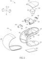
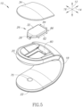
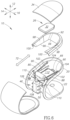
- the upper portion 20 may define an opening 186 for receiving the reservoir 26 and include a sloped surface 188 surrounding the opening 186 to guide the reservoir 26 into the opening 186.
- a seat 190 shaped to engage the shoulder 184 may also be positioned adjacent the opening 186.
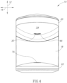
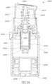
- a dispenser actuator drives a translation of piston 1904 along the translation axis.
- piston 1904 is driven to decrease an available storage volume in fluid reservoir 1950
- fluid housed in fluid reservoir 1950 flows out of reservoir 1950 through outlet port 1914.
- An available storage volume in fluid reservoir 1950 may be based on the cross section of reservoir body 1902 and a distance between piston 1904 and the second end of reservoir body 1902.
- the second end is a closed end.
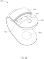
- Various user controls and/or user interfaces are included in dispenser 2100. At least one of the controls may be a touch sensitive control or sensor. Touch sensitive controls may be capacitive touch sensors. Touch sensitive sensors, controls, or components may be housed within dispenser's 2100 housing. The touch sensitive components can sense at least one of a touch, proximity of, or motion of a user's hand through housing. In preferred embodiments, sensing the proximity or motion of a user's hand underneath the dispensing aperture turns on the heating element to prepare the dispenser for use. Once the dispenser has heated the fluid adequately, a second positioning of the user's hand triggers a single dispensing event. For instance, when a user places a hand underneath the dispensing aperture, a proximity sensor may trigger the dispensing mechanism such that a volume of fluid is dispensed onto the user's hand.
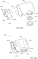
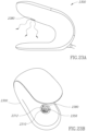
- Figs. 26A-26B provide views of another embodiment of a dispenser 2600 that includes a pivoting fluid reservoir receptacle assembly.
- Dispenser 2600 includes a housing and an aperture in the housing.
- the pivoting assembly is included as part of the dispenser housing.
- the pivoting assembly includes a receptacle, such as fluid reservoir receptacle 2770 of Fig. 27 .
- the receptacle is configured to removably receive a fluid reservoir, such as fluid reservoir 2650 of Fig. 26B . When the reservoir is received by the receptacle, an outlet port of the reservoir is exposed through the aperture.
- dispenser 2600 includes an actuator, such as stepper motor 2246 of Fig. 22C .
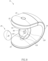
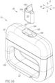
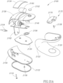
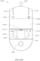
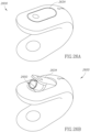
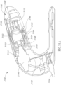
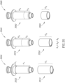
- reservoir 3150 is received by dispenser 3100.
- Reservoir 3150 includes a downwardly angled (when oriented in a vertical position) nozzle 3112.
- angled nozzle 3112 When received in the upwardly angled dispenser arm 3180, angled nozzle 3112 is oriented substantially vertical. This vertical orientation of nozzle 3112 enables a clear line of sight with the vertical for the dispensed fluid to flow into the hands of a user. The clear line of sight prevents dispensed fluid from contacting surfaces of the dispenser, thus decreasing the need for periodic cleaning of a dispenser's dispensing aperture, such as dispensing aperture 2380 of Figs. 23A-23B .
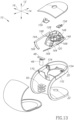
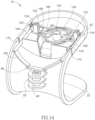
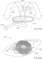
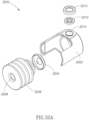
- Fig. 30 illustrates the downward translation of a nozzle assembly of reservoir 3050.
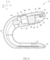
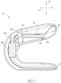
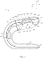
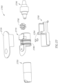
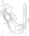
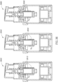
- dispenser 3100 includes one or more circuited boards that are populated with electronic components to control the operation of dispenser 3100. At least one of the circuit boards may be a printed circuit board (PCB).
- PCB printed circuit board
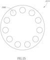
- dispenser 3100 includes an upper PCB 3164 that is populated with electronic components to control dispenser's 3100 night light, motion/touch sensors, various LED indicator's, inductive heating coils 3180, user controls, and the like.
- lower PCB 3162 houses electronics to control actuator 3146.
- Power cord 3104 provides electric power to upper PCB 3164, lower PCB 3162, actuator 3146, and other electrically driven elements of dispenser 3100. In preferred embodiments, power cord 3104 provides alternating current (AC) electrical power.
- AC alternating current
Landscapes
- Health & Medical Sciences (AREA)
- Public Health (AREA)
- Physics & Mathematics (AREA)
- Electromagnetism (AREA)
- Containers And Packaging Bodies Having A Special Means To Remove Contents (AREA)
- Coating Apparatus (AREA)
- Infusion, Injection, And Reservoir Apparatuses (AREA)
- Rigid Pipes And Flexible Pipes (AREA)
Claims (12)
- Capsule de distribution de fluide comprenant:une première surface (3306);une seconde surface (3330) opposée à la première surface;un corps de réservoir (3302) situé entre les première et seconde surfaces (3306, 3330), dans laquelle le corps de réservoir (3302) est configuré pour loger un fluide;un orifice de sortie (3312) en communication fluidique avec le corps de réservoir (3302);une structure chauffante située à l'intérieur du corps de réservoir (3302) et électriquement conductrice pour recevoir sans fil de l'énergie inductive d'une source d'énergie (3180) qui est externe au corps de réservoir de fluide (3302) pour chauffer au moins une partie du fluide à l'intérieur du corps de réservoir; etun ensemble soupape (3432) qui est opérationnel pour, en réponse à une application de forces de compression sur les première et seconde surfaces opposées (3306, 3330), distribuer au moins une partie du fluide chauffé à travers l'orifice de sortie (3312);dans laquelle la structure chauffante est un tube conducteur (3410) ayant une longueur qui est basée sur une capacité thermique spécifique du fluide logé dans le corps de réservoir (3302);dans laquelle l'ensemble soupape (3432) comporte une chambre inférieure (3424) et le tube chauffant conducteur (3410) est positionné autour d'au moins une partie de la chambre inférieure de l'ensemble soupape (3432); etdans laquelle le tube chauffant conducteur (3410) a des bords longitudinaux qui sont soudés ou sertis pour être assemblés.
- Capsule selon la revendication 1, dans laquelle une dimension physique du tube chauffant conducteur (3410) est basée sur un type de fluide du fluide logé à l'intérieur du corps de réservoir (3302).
- Capsule selon la revendication 1, dans laquelle la chambre inférieure (3424) de l'ensemble soupape (3432) et le tube chauffant conducteur (3410) sont coaxiaux le long d'un axe qui s'étend entre les première et seconde surfaces (3306, 3330).
- Capsule selon la revendication 1, dans laquelle le tube chauffant conducteur (3410) présente une longueur, un rayon intérieur, et un rayon extérieur.
- Capsule selon la revendication 4, dans laquelle la longueur du tube chauffant conducteur (3410) est comprise entre 13 et 17 millimètres.
- Capsule selon la revendication 4, dans laquelle la longueur du tube chauffant conducteur (3410) est comprise entre 3 et 7 millimètres.
- Capsule selon la revendication 1, dans laquelle une chambre inférieure (3424) de l'ensemble soupape (3432) reçoit de manière coulissante le tube chauffant conducteur (3410).
- Capsule selon la revendication 1, dans laquelle le tube chauffant conducteur (3410) comporte une ouverture (3426) dotée d'un rayon intérieur et d'un rayon extérieur, ladite ouverture (3426) étant configurée et agencée pour recevoir au moins une partie d'une chambre inférieure (3424) de l'ensemble soupape (3432) .
- Capsule selon la revendication 8, dans laquelle au moins l'un parmi le rayon extérieur ou le rayon intérieur du tube chauffant conducteur (3410) est basé sur un type de fluide du fluide logé dans le volume du corps de réservoir (3302).
- Capsule selon la revendication 8, dans laquelle le rayon extérieur du tube chauffant conducteur (3410) est compris entre 6 mm et 10 mm.
- Capsule selon la revendication 8, dans lequel le tube chauffant conducteur (3410) comporte au moins une région soudée.
- Capsule selon la revendication 1, comprenant en outre:
un piston (2804) logé dans le volume du corps de réservoir (3302) et configuré et agencé pour se déplacer le long d'un axe de translation lors d'une application des forces de compression, les forces de compression étant appliquées à l'aide d'un actionneur (3146), l'actionneur s'accouple avec le piston (2804) et l'actionneur fournit les forces de distribution sur le piston.
Applications Claiming Priority (2)
| Application Number | Priority Date | Filing Date | Title |
|---|---|---|---|
| US14/879,014 US10189038B2 (en) | 2013-12-20 | 2015-10-08 | Inductively heatable fluid reservoir for various fluid types |
| PCT/US2016/055375 WO2017062387A1 (fr) | 2015-10-08 | 2016-10-04 | Réservoir de fluide pouvant être chauffé par induction destiné à divers types de fluide |
Publications (3)
| Publication Number | Publication Date |
|---|---|
| EP3359005A1 EP3359005A1 (fr) | 2018-08-15 |
| EP3359005C0 EP3359005C0 (fr) | 2023-09-20 |
| EP3359005B1 true EP3359005B1 (fr) | 2023-09-20 |
Family
ID=58488404
Family Applications (1)
| Application Number | Title | Priority Date | Filing Date |
|---|---|---|---|
| EP16781650.3A Active EP3359005B1 (fr) | 2015-10-08 | 2016-10-04 | Réservoir de fluide pouvant être chauffé par induction destiné à divers types de fluide |
Country Status (6)
| Country | Link |
|---|---|
| EP (1) | EP3359005B1 (fr) |
| JP (1) | JP2018538203A (fr) |
| KR (1) | KR102414083B1 (fr) |
| CN (1) | CN108471914B (fr) |
| CA (1) | CA3003724C (fr) |
| WO (1) | WO2017062387A1 (fr) |
Families Citing this family (1)
| Publication number | Priority date | Publication date | Assignee | Title |
|---|---|---|---|---|
| FR3076198B1 (fr) * | 2018-01-02 | 2020-01-03 | Sebastien Fauconnier | Dispositif de distribution experientiel d'un produit cosmetique |
Family Cites Families (16)
| Publication number | Priority date | Publication date | Assignee | Title |
|---|---|---|---|---|
| CN2179090Y (zh) * | 1993-03-08 | 1994-10-12 | 苗超英 | 自动洁手器 |
| JP3144399B2 (ja) * | 1998-11-04 | 2001-03-12 | タイガー魔法瓶株式会社 | 電気貯湯容器 |
| US6454127B1 (en) * | 2000-08-17 | 2002-09-24 | Sheree Suomela | Self-contained liquid dispenser with heating means |
| MXPA06000112A (es) * | 2003-06-27 | 2006-04-27 | Johnson & Son Inc S C | Sistemas y ensambles distribuidores incluyendo una unidad de almacenamiento de calor. |
| US7774096B2 (en) * | 2003-12-31 | 2010-08-10 | Kimberly-Clark Worldwide, Inc. | Apparatus for dispensing and identifying product in washrooms |
| GB0510707D0 (en) * | 2005-05-26 | 2005-06-29 | Incro Ltd | A check valve and a pump-action dispenser device having such a check valve |
| US8061918B2 (en) * | 2006-04-13 | 2011-11-22 | S.C. Johnson & Son, Inc. | Heated flowable product dispenser |
| MX2010007232A (es) * | 2008-02-18 | 2011-02-23 | Sca Hygiene Prod Ab | Bomba desechable, sistema despachador que comprende una bomba y metodo para despachar liquido. |
| CN201219852Y (zh) * | 2008-06-20 | 2009-04-15 | 张贵堂 | 清洁用品供给装置 |
| KR101194121B1 (ko) * | 2010-03-16 | 2012-10-24 | 황원우 | 발열수단이 구비된 화장품 케이스 |
| US8708246B2 (en) * | 2011-10-28 | 2014-04-29 | Nordson Corporation | Positive displacement dispenser and method for dispensing discrete amounts of liquid |
| CA2776684C (fr) * | 2012-05-11 | 2019-07-23 | Gotohti.Com Inc. | Distributeur de mousse ozonee |
| CA2780503C (fr) * | 2012-06-19 | 2019-05-21 | Gotohti.Com Inc. | Piston de cloche telescopique pour pompe |
| US9974416B2 (en) * | 2013-12-20 | 2018-05-22 | Toaster Labs, Inc. | Automatic heated fluid dispenser |
| US10144032B2 (en) * | 2013-12-20 | 2018-12-04 | Toaster Labs, Inc. | Inductively heatable fluid reservoir |
| US9967924B2 (en) * | 2014-02-25 | 2018-05-08 | James Heczko | Package for storing consumable product, induction heating apparatus for heating package and system including same |
-
2016
- 2016-10-04 CN CN201680072235.9A patent/CN108471914B/zh active Active
- 2016-10-04 WO PCT/US2016/055375 patent/WO2017062387A1/fr active Application Filing
- 2016-10-04 JP JP2018517814A patent/JP2018538203A/ja active Pending
- 2016-10-04 CA CA3003724A patent/CA3003724C/fr active Active
- 2016-10-04 EP EP16781650.3A patent/EP3359005B1/fr active Active
- 2016-10-04 KR KR1020187013089A patent/KR102414083B1/ko active IP Right Grant
Also Published As
| Publication number | Publication date |
|---|---|
| EP3359005C0 (fr) | 2023-09-20 |
| EP3359005A1 (fr) | 2018-08-15 |
| CA3003724C (fr) | 2023-12-12 |
| WO2017062387A1 (fr) | 2017-04-13 |
| CN108471914B (zh) | 2020-10-23 |
| JP2018538203A (ja) | 2018-12-27 |
| KR20180081063A (ko) | 2018-07-13 |
| CA3003724A1 (fr) | 2017-04-13 |
| KR102414083B1 (ko) | 2022-06-27 |
| CN108471914A (zh) | 2018-08-31 |
Similar Documents
| Publication | Publication Date | Title |
|---|---|---|
| US10144032B2 (en) | Inductively heatable fluid reservoir | |
| US9974416B2 (en) | Automatic heated fluid dispenser | |
| US10189038B2 (en) | Inductively heatable fluid reservoir for various fluid types | |
| EP3212053B1 (fr) | Dispositif de fluide chauffé automatiquement | |
| US10433372B2 (en) | Portable fluid warming device | |
| EP3359005B1 (fr) | Réservoir de fluide pouvant être chauffé par induction destiné à divers types de fluide | |
| US10098510B2 (en) | Pneumatically driven fluid dispenser | |
| EP3212052B1 (fr) | Réservoir de fluide pouvant être chauffé par induction | |
| CA3003723C (fr) | Dispositif de chauffage de fluide portatif |
Legal Events
| Date | Code | Title | Description |
|---|---|---|---|
| STAA | Information on the status of an ep patent application or granted ep patent |
Free format text: STATUS: THE INTERNATIONAL PUBLICATION HAS BEEN MADE |
|
| PUAI | Public reference made under article 153(3) epc to a published international application that has entered the european phase |
Free format text: ORIGINAL CODE: 0009012 |
|
| STAA | Information on the status of an ep patent application or granted ep patent |
Free format text: STATUS: REQUEST FOR EXAMINATION WAS MADE |
|
| 17P | Request for examination filed |
Effective date: 20180507 |
|
| AK | Designated contracting states |
Kind code of ref document: A1 Designated state(s): AL AT BE BG CH CY CZ DE DK EE ES FI FR GB GR HR HU IE IS IT LI LT LU LV MC MK MT NL NO PL PT RO RS SE SI SK SM TR |
|
| AX | Request for extension of the european patent |
Extension state: BA ME |
|
| DAV | Request for validation of the european patent (deleted) | ||
| DAX | Request for extension of the european patent (deleted) | ||
| RAP1 | Party data changed (applicant data changed or rights of an application transferred) |
Owner name: TOASTER LABS, INC. |
|
| RIN1 | Information on inventor provided before grant (corrected) |
Inventor name: HORTH, ROLAND, DAVID Inventor name: BUCKALTER, AMY, CAROL Inventor name: NENNINGER, GARET, GLENN Inventor name: IVERSON, DAVID, OSCARD |
|
| STAA | Information on the status of an ep patent application or granted ep patent |
Free format text: STATUS: EXAMINATION IS IN PROGRESS |
|
| 17Q | First examination report despatched |
Effective date: 20190523 |
|
| STAA | Information on the status of an ep patent application or granted ep patent |
Free format text: STATUS: EXAMINATION IS IN PROGRESS |
|
| STAA | Information on the status of an ep patent application or granted ep patent |
Free format text: STATUS: EXAMINATION IS IN PROGRESS |
|
| GRAP | Despatch of communication of intention to grant a patent |
Free format text: ORIGINAL CODE: EPIDOSNIGR1 |
|
| STAA | Information on the status of an ep patent application or granted ep patent |
Free format text: STATUS: GRANT OF PATENT IS INTENDED |
|
| INTG | Intention to grant announced |
Effective date: 20230411 |
|
| GRAS | Grant fee paid |
Free format text: ORIGINAL CODE: EPIDOSNIGR3 |
|
| GRAA | (expected) grant |
Free format text: ORIGINAL CODE: 0009210 |
|
| STAA | Information on the status of an ep patent application or granted ep patent |
Free format text: STATUS: THE PATENT HAS BEEN GRANTED |
|
| AK | Designated contracting states |
Kind code of ref document: B1 Designated state(s): AL AT BE BG CH CY CZ DE DK EE ES FI FR GB GR HR HU IE IS IT LI LT LU LV MC MK MT NL NO PL PT RO RS SE SI SK SM TR |
|
| REG | Reference to a national code |
Ref country code: GB Ref legal event code: FG4D |
|
| REG | Reference to a national code |
Ref country code: CH Ref legal event code: EP |
|
| REG | Reference to a national code |
Ref country code: DE Ref legal event code: R096 Ref document number: 602016082898 Country of ref document: DE |
|
| REG | Reference to a national code |
Ref country code: IE Ref legal event code: FG4D |
|
| U01 | Request for unitary effect filed |
Effective date: 20231019 |
|
| U07 | Unitary effect registered |
Designated state(s): AT BE BG DE DK EE FI FR IT LT LU LV MT NL PT SE SI Effective date: 20231025 |
|
| PG25 | Lapsed in a contracting state [announced via postgrant information from national office to epo] |
Ref country code: GR Free format text: LAPSE BECAUSE OF FAILURE TO SUBMIT A TRANSLATION OF THE DESCRIPTION OR TO PAY THE FEE WITHIN THE PRESCRIBED TIME-LIMIT Effective date: 20231221 |
|
| PGFP | Annual fee paid to national office [announced via postgrant information from national office to epo] |
Ref country code: GB Payment date: 20231206 Year of fee payment: 8 |
|
| REG | Reference to a national code |
Ref country code: NO Ref legal event code: T2 Effective date: 20230920 |
|
| PG25 | Lapsed in a contracting state [announced via postgrant information from national office to epo] |
Ref country code: RS Free format text: LAPSE BECAUSE OF FAILURE TO SUBMIT A TRANSLATION OF THE DESCRIPTION OR TO PAY THE FEE WITHIN THE PRESCRIBED TIME-LIMIT Effective date: 20230920 Ref country code: HR Free format text: LAPSE BECAUSE OF FAILURE TO SUBMIT A TRANSLATION OF THE DESCRIPTION OR TO PAY THE FEE WITHIN THE PRESCRIBED TIME-LIMIT Effective date: 20230920 Ref country code: GR Free format text: LAPSE BECAUSE OF FAILURE TO SUBMIT A TRANSLATION OF THE DESCRIPTION OR TO PAY THE FEE WITHIN THE PRESCRIBED TIME-LIMIT Effective date: 20231221 |
|
| PGFP | Annual fee paid to national office [announced via postgrant information from national office to epo] |
Ref country code: NO Payment date: 20231207 Year of fee payment: 8 Ref country code: CH Payment date: 20231212 Year of fee payment: 8 |
|
| U20 | Renewal fee paid [unitary effect] |
Year of fee payment: 8 Effective date: 20240115 |
|
| PG25 | Lapsed in a contracting state [announced via postgrant information from national office to epo] |
Ref country code: IS Free format text: LAPSE BECAUSE OF FAILURE TO SUBMIT A TRANSLATION OF THE DESCRIPTION OR TO PAY THE FEE WITHIN THE PRESCRIBED TIME-LIMIT Effective date: 20240120 |
|
| PG25 | Lapsed in a contracting state [announced via postgrant information from national office to epo] |
Ref country code: ES Free format text: LAPSE BECAUSE OF FAILURE TO SUBMIT A TRANSLATION OF THE DESCRIPTION OR TO PAY THE FEE WITHIN THE PRESCRIBED TIME-LIMIT Effective date: 20230920 |
|
| PG25 | Lapsed in a contracting state [announced via postgrant information from national office to epo] |
Ref country code: SM Free format text: LAPSE BECAUSE OF FAILURE TO SUBMIT A TRANSLATION OF THE DESCRIPTION OR TO PAY THE FEE WITHIN THE PRESCRIBED TIME-LIMIT Effective date: 20230920 Ref country code: RO Free format text: LAPSE BECAUSE OF FAILURE TO SUBMIT A TRANSLATION OF THE DESCRIPTION OR TO PAY THE FEE WITHIN THE PRESCRIBED TIME-LIMIT Effective date: 20230920 Ref country code: IS Free format text: LAPSE BECAUSE OF FAILURE TO SUBMIT A TRANSLATION OF THE DESCRIPTION OR TO PAY THE FEE WITHIN THE PRESCRIBED TIME-LIMIT Effective date: 20240120 Ref country code: ES Free format text: LAPSE BECAUSE OF FAILURE TO SUBMIT A TRANSLATION OF THE DESCRIPTION OR TO PAY THE FEE WITHIN THE PRESCRIBED TIME-LIMIT Effective date: 20230920 Ref country code: CZ Free format text: LAPSE BECAUSE OF FAILURE TO SUBMIT A TRANSLATION OF THE DESCRIPTION OR TO PAY THE FEE WITHIN THE PRESCRIBED TIME-LIMIT Effective date: 20230920 Ref country code: SK Free format text: LAPSE BECAUSE OF FAILURE TO SUBMIT A TRANSLATION OF THE DESCRIPTION OR TO PAY THE FEE WITHIN THE PRESCRIBED TIME-LIMIT Effective date: 20230920 |
|
| PG25 | Lapsed in a contracting state [announced via postgrant information from national office to epo] |
Ref country code: PL Free format text: LAPSE BECAUSE OF FAILURE TO SUBMIT A TRANSLATION OF THE DESCRIPTION OR TO PAY THE FEE WITHIN THE PRESCRIBED TIME-LIMIT Effective date: 20230920 |
|
| REG | Reference to a national code |
Ref country code: DE Ref legal event code: R097 Ref document number: 602016082898 Country of ref document: DE |
|
| PG25 | Lapsed in a contracting state [announced via postgrant information from national office to epo] |
Ref country code: MC Free format text: LAPSE BECAUSE OF FAILURE TO SUBMIT A TRANSLATION OF THE DESCRIPTION OR TO PAY THE FEE WITHIN THE PRESCRIBED TIME-LIMIT Effective date: 20230920 |
|
| PLBE | No opposition filed within time limit |
Free format text: ORIGINAL CODE: 0009261 |
|
| STAA | Information on the status of an ep patent application or granted ep patent |
Free format text: STATUS: NO OPPOSITION FILED WITHIN TIME LIMIT |
|
| PG25 | Lapsed in a contracting state [announced via postgrant information from national office to epo] |
Ref country code: MC Free format text: LAPSE BECAUSE OF FAILURE TO SUBMIT A TRANSLATION OF THE DESCRIPTION OR TO PAY THE FEE WITHIN THE PRESCRIBED TIME-LIMIT Effective date: 20230920 |
|
| 26N | No opposition filed |
Effective date: 20240621 |