EP3358706A1 - Système d'alimentation électrique - Google Patents
Système d'alimentation électrique Download PDFInfo
- Publication number
- EP3358706A1 EP3358706A1 EP16851454.5A EP16851454A EP3358706A1 EP 3358706 A1 EP3358706 A1 EP 3358706A1 EP 16851454 A EP16851454 A EP 16851454A EP 3358706 A1 EP3358706 A1 EP 3358706A1
- Authority
- EP
- European Patent Office
- Prior art keywords
- storage pack
- curve
- charging
- voltage
- power supplying
- Prior art date
- Legal status (The legal status is an assumption and is not a legal conclusion. Google has not performed a legal analysis and makes no representation as to the accuracy of the status listed.)
- Granted
Links
- 238000007599 discharging Methods 0.000 claims abstract description 234
- 238000007600 charging Methods 0.000 claims abstract description 232
- 230000007246 mechanism Effects 0.000 claims abstract description 100
- HBBGRARXTFLTSG-UHFFFAOYSA-N Lithium ion Chemical compound [Li+] HBBGRARXTFLTSG-UHFFFAOYSA-N 0.000 claims description 147
- 229910001416 lithium ion Inorganic materials 0.000 claims description 147
- 239000007773 negative electrode material Substances 0.000 claims description 70
- 239000007774 positive electrode material Substances 0.000 claims description 64
- PXHVJJICTQNCMI-UHFFFAOYSA-N nickel Substances [Ni] PXHVJJICTQNCMI-UHFFFAOYSA-N 0.000 claims description 54
- -1 nickel hydrogen Chemical class 0.000 claims description 21
- 229910052759 nickel Inorganic materials 0.000 claims description 13
- 229910052739 hydrogen Inorganic materials 0.000 claims description 12
- 239000001257 hydrogen Substances 0.000 claims description 12
- 229910052744 lithium Inorganic materials 0.000 claims description 8
- 229910001367 Li3V2(PO4)3 Inorganic materials 0.000 claims description 4
- 230000009467 reduction Effects 0.000 abstract description 30
- OKTJSMMVPCPJKN-UHFFFAOYSA-N Carbon Chemical compound [C] OKTJSMMVPCPJKN-UHFFFAOYSA-N 0.000 description 44
- 229910002804 graphite Inorganic materials 0.000 description 44
- 239000010439 graphite Substances 0.000 description 44
- 229910052493 LiFePO4 Inorganic materials 0.000 description 34
- 238000006243 chemical reaction Methods 0.000 description 23
- 229910002986 Li4Ti5O12 Inorganic materials 0.000 description 22
- 229910002097 Lithium manganese(III,IV) oxide Inorganic materials 0.000 description 21
- 238000000034 method Methods 0.000 description 18
- LIVNPJMFVYWSIS-UHFFFAOYSA-N silicon monoxide Chemical compound [Si-]#[O+] LIVNPJMFVYWSIS-UHFFFAOYSA-N 0.000 description 14
- XOLBLPGZBRYERU-UHFFFAOYSA-N tin dioxide Chemical compound O=[Sn]=O XOLBLPGZBRYERU-UHFFFAOYSA-N 0.000 description 14
- 229910021469 graphitizable carbon Inorganic materials 0.000 description 12
- 229910052723 transition metal Inorganic materials 0.000 description 10
- 229910001228 Li[Ni1/3Co1/3Mn1/3]O2 (NCM 111) Inorganic materials 0.000 description 9
- 229910021385 hard carbon Inorganic materials 0.000 description 9
- 230000015556 catabolic process Effects 0.000 description 8
- 238000006731 degradation reaction Methods 0.000 description 8
- 239000000203 mixture Substances 0.000 description 8
- 238000010586 diagram Methods 0.000 description 7
- 238000012806 monitoring device Methods 0.000 description 6
- 230000002035 prolonged effect Effects 0.000 description 6
- 229910011279 LiCoPO4 Inorganic materials 0.000 description 5
- 238000012544 monitoring process Methods 0.000 description 5
- WHXSMMKQMYFTQS-UHFFFAOYSA-N Lithium Chemical compound [Li] WHXSMMKQMYFTQS-UHFFFAOYSA-N 0.000 description 4
- 239000003990 capacitor Substances 0.000 description 4
- 239000002131 composite material Substances 0.000 description 4
- 150000002484 inorganic compounds Chemical class 0.000 description 4
- 229910010272 inorganic material Inorganic materials 0.000 description 4
- NUJOXMJBOLGQSY-UHFFFAOYSA-N manganese dioxide Chemical compound O=[Mn]=O NUJOXMJBOLGQSY-UHFFFAOYSA-N 0.000 description 4
- 150000002894 organic compounds Chemical class 0.000 description 4
- 150000003624 transition metals Chemical class 0.000 description 4
- 229910032387 LiCoO2 Inorganic materials 0.000 description 3
- 229910000668 LiMnPO4 Inorganic materials 0.000 description 3
- 229910016765 Ni0.5Mn1.5 Inorganic materials 0.000 description 3
- 229910003932 NixMnyCozO2 Inorganic materials 0.000 description 3
- 150000001875 compounds Chemical class 0.000 description 3
- 239000000463 material Substances 0.000 description 3
- 230000004048 modification Effects 0.000 description 3
- 238000012986 modification Methods 0.000 description 3
- PXLYGWXKAVCTPX-UHFFFAOYSA-N 1,2,3,4,5,6-hexamethylidenecyclohexane Chemical class C=C1C(=C)C(=C)C(=C)C(=C)C1=C PXLYGWXKAVCTPX-UHFFFAOYSA-N 0.000 description 2
- 229910011916 Li4Ti3O12 Inorganic materials 0.000 description 2
- VYPSYNLAJGMNEJ-UHFFFAOYSA-N Silicium dioxide Chemical compound O=[Si]=O VYPSYNLAJGMNEJ-UHFFFAOYSA-N 0.000 description 2
- GWEVSGVZZGPLCZ-UHFFFAOYSA-N Titan oxide Chemical compound O=[Ti]=O GWEVSGVZZGPLCZ-UHFFFAOYSA-N 0.000 description 2
- 229910045601 alloy Inorganic materials 0.000 description 2
- 239000000956 alloy Substances 0.000 description 2
- 230000015572 biosynthetic process Effects 0.000 description 2
- 239000003575 carbonaceous material Substances 0.000 description 2
- 230000008859 change Effects 0.000 description 2
- 238000010277 constant-current charging Methods 0.000 description 2
- 125000005331 diazinyl group Chemical class N1=NC(=CC=C1)* 0.000 description 2
- QXYJCZRRLLQGCR-UHFFFAOYSA-N dioxomolybdenum Chemical compound O=[Mo]=O QXYJCZRRLLQGCR-UHFFFAOYSA-N 0.000 description 2
- 150000002019 disulfides Chemical class 0.000 description 2
- OAEGRYMCJYIXQT-UHFFFAOYSA-N dithiooxamide Chemical class NC(=S)C(N)=S OAEGRYMCJYIXQT-UHFFFAOYSA-N 0.000 description 2
- 229910044991 metal oxide Inorganic materials 0.000 description 2
- 150000004706 metal oxides Chemical class 0.000 description 2
- 238000010248 power generation Methods 0.000 description 2
- 150000004053 quinones Chemical class 0.000 description 2
- 229910021384 soft carbon Inorganic materials 0.000 description 2
- 238000003786 synthesis reaction Methods 0.000 description 2
- 229910000314 transition metal oxide Inorganic materials 0.000 description 2
- 229910007404 Li2Ti3O7 Inorganic materials 0.000 description 1
- 229910012652 LiCo1 Inorganic materials 0.000 description 1
- 229910011623 LiCrTiO4 Inorganic materials 0.000 description 1
- 229910010759 LiFeTiO4 Inorganic materials 0.000 description 1
- 229910002993 LiMnO2 Inorganic materials 0.000 description 1
- 229910003005 LiNiO2 Inorganic materials 0.000 description 1
- 229910013084 LiNiPO4 Inorganic materials 0.000 description 1
- 229910013124 LiNiVO4 Inorganic materials 0.000 description 1
- 229910012999 LiVOPO4 Inorganic materials 0.000 description 1
- 229910021541 Vanadium(III) oxide Inorganic materials 0.000 description 1
- 230000005856 abnormality Effects 0.000 description 1
- 239000011149 active material Substances 0.000 description 1
- 229910052804 chromium Inorganic materials 0.000 description 1
- 229910052681 coesite Inorganic materials 0.000 description 1
- 238000002485 combustion reaction Methods 0.000 description 1
- 229910052906 cristobalite Inorganic materials 0.000 description 1
- 230000000694 effects Effects 0.000 description 1
- 230000005669 field effect Effects 0.000 description 1
- 239000000446 fuel Substances 0.000 description 1
- 230000020169 heat generation Effects 0.000 description 1
- 238000012423 maintenance Methods 0.000 description 1
- 229910052748 manganese Inorganic materials 0.000 description 1
- 238000013021 overheating Methods 0.000 description 1
- 239000000377 silicon dioxide Substances 0.000 description 1
- 230000000087 stabilizing effect Effects 0.000 description 1
- 229910052682 stishovite Inorganic materials 0.000 description 1
- 229910052718 tin Inorganic materials 0.000 description 1
- 229910052905 tridymite Inorganic materials 0.000 description 1
- ZNOKGRXACCSDPY-UHFFFAOYSA-N tungsten(VI) oxide Inorganic materials O=[W](=O)=O ZNOKGRXACCSDPY-UHFFFAOYSA-N 0.000 description 1
Images


Classifications
-
- H—ELECTRICITY
- H02—GENERATION; CONVERSION OR DISTRIBUTION OF ELECTRIC POWER
- H02J—CIRCUIT ARRANGEMENTS OR SYSTEMS FOR SUPPLYING OR DISTRIBUTING ELECTRIC POWER; SYSTEMS FOR STORING ELECTRIC ENERGY
- H02J7/00—Circuit arrangements for charging or depolarising batteries or for supplying loads from batteries
- H02J7/34—Parallel operation in networks using both storage and other dc sources, e.g. providing buffering
-
- H—ELECTRICITY
- H01—ELECTRIC ELEMENTS
- H01M—PROCESSES OR MEANS, e.g. BATTERIES, FOR THE DIRECT CONVERSION OF CHEMICAL ENERGY INTO ELECTRICAL ENERGY
- H01M10/00—Secondary cells; Manufacture thereof
- H01M10/05—Accumulators with non-aqueous electrolyte
- H01M10/052—Li-accumulators
-
- H—ELECTRICITY
- H01—ELECTRIC ELEMENTS
- H01M—PROCESSES OR MEANS, e.g. BATTERIES, FOR THE DIRECT CONVERSION OF CHEMICAL ENERGY INTO ELECTRICAL ENERGY
- H01M10/00—Secondary cells; Manufacture thereof
- H01M10/42—Methods or arrangements for servicing or maintenance of secondary cells or secondary half-cells
- H01M10/425—Structural combination with electronic components, e.g. electronic circuits integrated to the outside of the casing
-
- H—ELECTRICITY
- H01—ELECTRIC ELEMENTS
- H01M—PROCESSES OR MEANS, e.g. BATTERIES, FOR THE DIRECT CONVERSION OF CHEMICAL ENERGY INTO ELECTRICAL ENERGY
- H01M10/00—Secondary cells; Manufacture thereof
- H01M10/42—Methods or arrangements for servicing or maintenance of secondary cells or secondary half-cells
- H01M10/44—Methods for charging or discharging
- H01M10/441—Methods for charging or discharging for several batteries or cells simultaneously or sequentially
-
- H—ELECTRICITY
- H01—ELECTRIC ELEMENTS
- H01M—PROCESSES OR MEANS, e.g. BATTERIES, FOR THE DIRECT CONVERSION OF CHEMICAL ENERGY INTO ELECTRICAL ENERGY
- H01M10/00—Secondary cells; Manufacture thereof
- H01M10/42—Methods or arrangements for servicing or maintenance of secondary cells or secondary half-cells
- H01M10/46—Accumulators structurally combined with charging apparatus
-
- H—ELECTRICITY
- H01—ELECTRIC ELEMENTS
- H01M—PROCESSES OR MEANS, e.g. BATTERIES, FOR THE DIRECT CONVERSION OF CHEMICAL ENERGY INTO ELECTRICAL ENERGY
- H01M10/00—Secondary cells; Manufacture thereof
- H01M10/42—Methods or arrangements for servicing or maintenance of secondary cells or secondary half-cells
- H01M10/48—Accumulators combined with arrangements for measuring, testing or indicating the condition of cells, e.g. the level or density of the electrolyte
-
- H—ELECTRICITY
- H01—ELECTRIC ELEMENTS
- H01M—PROCESSES OR MEANS, e.g. BATTERIES, FOR THE DIRECT CONVERSION OF CHEMICAL ENERGY INTO ELECTRICAL ENERGY
- H01M16/00—Structural combinations of different types of electrochemical generators
-
- H—ELECTRICITY
- H01—ELECTRIC ELEMENTS
- H01M—PROCESSES OR MEANS, e.g. BATTERIES, FOR THE DIRECT CONVERSION OF CHEMICAL ENERGY INTO ELECTRICAL ENERGY
- H01M4/00—Electrodes
- H01M4/02—Electrodes composed of, or comprising, active material
- H01M4/13—Electrodes for accumulators with non-aqueous electrolyte, e.g. for lithium-accumulators; Processes of manufacture thereof
- H01M4/131—Electrodes based on mixed oxides or hydroxides, or on mixtures of oxides or hydroxides, e.g. LiCoOx
-
- H—ELECTRICITY
- H01—ELECTRIC ELEMENTS
- H01M—PROCESSES OR MEANS, e.g. BATTERIES, FOR THE DIRECT CONVERSION OF CHEMICAL ENERGY INTO ELECTRICAL ENERGY
- H01M4/00—Electrodes
- H01M4/02—Electrodes composed of, or comprising, active material
- H01M4/36—Selection of substances as active materials, active masses, active liquids
- H01M4/362—Composites
- H01M4/364—Composites as mixtures
-
- H—ELECTRICITY
- H01—ELECTRIC ELEMENTS
- H01M—PROCESSES OR MEANS, e.g. BATTERIES, FOR THE DIRECT CONVERSION OF CHEMICAL ENERGY INTO ELECTRICAL ENERGY
- H01M4/00—Electrodes
- H01M4/02—Electrodes composed of, or comprising, active material
- H01M4/36—Selection of substances as active materials, active masses, active liquids
- H01M4/48—Selection of substances as active materials, active masses, active liquids of inorganic oxides or hydroxides
- H01M4/50—Selection of substances as active materials, active masses, active liquids of inorganic oxides or hydroxides of manganese
- H01M4/505—Selection of substances as active materials, active masses, active liquids of inorganic oxides or hydroxides of manganese of mixed oxides or hydroxides containing manganese for inserting or intercalating light metals, e.g. LiMn2O4 or LiMn2OxFy
-
- H—ELECTRICITY
- H01—ELECTRIC ELEMENTS
- H01M—PROCESSES OR MEANS, e.g. BATTERIES, FOR THE DIRECT CONVERSION OF CHEMICAL ENERGY INTO ELECTRICAL ENERGY
- H01M4/00—Electrodes
- H01M4/02—Electrodes composed of, or comprising, active material
- H01M4/36—Selection of substances as active materials, active masses, active liquids
- H01M4/48—Selection of substances as active materials, active masses, active liquids of inorganic oxides or hydroxides
- H01M4/52—Selection of substances as active materials, active masses, active liquids of inorganic oxides or hydroxides of nickel, cobalt or iron
- H01M4/525—Selection of substances as active materials, active masses, active liquids of inorganic oxides or hydroxides of nickel, cobalt or iron of mixed oxides or hydroxides containing iron, cobalt or nickel for inserting or intercalating light metals, e.g. LiNiO2, LiCoO2 or LiCoOxFy
-
- H—ELECTRICITY
- H01—ELECTRIC ELEMENTS
- H01M—PROCESSES OR MEANS, e.g. BATTERIES, FOR THE DIRECT CONVERSION OF CHEMICAL ENERGY INTO ELECTRICAL ENERGY
- H01M4/00—Electrodes
- H01M4/02—Electrodes composed of, or comprising, active material
- H01M4/36—Selection of substances as active materials, active masses, active liquids
- H01M4/58—Selection of substances as active materials, active masses, active liquids of inorganic compounds other than oxides or hydroxides, e.g. sulfides, selenides, tellurides, halogenides or LiCoFy; of polyanionic structures, e.g. phosphates, silicates or borates
- H01M4/5825—Oxygenated metallic salts or polyanionic structures, e.g. borates, phosphates, silicates, olivines
-
- H—ELECTRICITY
- H01—ELECTRIC ELEMENTS
- H01M—PROCESSES OR MEANS, e.g. BATTERIES, FOR THE DIRECT CONVERSION OF CHEMICAL ENERGY INTO ELECTRICAL ENERGY
- H01M50/00—Constructional details or processes of manufacture of the non-active parts of electrochemical cells other than fuel cells, e.g. hybrid cells
- H01M50/20—Mountings; Secondary casings or frames; Racks, modules or packs; Suspension devices; Shock absorbers; Transport or carrying devices; Holders
- H01M50/204—Racks, modules or packs for multiple batteries or multiple cells
-
- H—ELECTRICITY
- H02—GENERATION; CONVERSION OR DISTRIBUTION OF ELECTRIC POWER
- H02J—CIRCUIT ARRANGEMENTS OR SYSTEMS FOR SUPPLYING OR DISTRIBUTING ELECTRIC POWER; SYSTEMS FOR STORING ELECTRIC ENERGY
- H02J7/00—Circuit arrangements for charging or depolarising batteries or for supplying loads from batteries
-
- H—ELECTRICITY
- H01—ELECTRIC ELEMENTS
- H01M—PROCESSES OR MEANS, e.g. BATTERIES, FOR THE DIRECT CONVERSION OF CHEMICAL ENERGY INTO ELECTRICAL ENERGY
- H01M10/00—Secondary cells; Manufacture thereof
- H01M10/24—Alkaline accumulators
- H01M10/30—Nickel accumulators
-
- H—ELECTRICITY
- H01—ELECTRIC ELEMENTS
- H01M—PROCESSES OR MEANS, e.g. BATTERIES, FOR THE DIRECT CONVERSION OF CHEMICAL ENERGY INTO ELECTRICAL ENERGY
- H01M10/00—Secondary cells; Manufacture thereof
- H01M10/42—Methods or arrangements for servicing or maintenance of secondary cells or secondary half-cells
- H01M10/46—Accumulators structurally combined with charging apparatus
- H01M10/465—Accumulators structurally combined with charging apparatus with solar battery as charging system
-
- H—ELECTRICITY
- H01—ELECTRIC ELEMENTS
- H01M—PROCESSES OR MEANS, e.g. BATTERIES, FOR THE DIRECT CONVERSION OF CHEMICAL ENERGY INTO ELECTRICAL ENERGY
- H01M4/00—Electrodes
- H01M4/02—Electrodes composed of, or comprising, active material
- H01M2004/026—Electrodes composed of, or comprising, active material characterised by the polarity
- H01M2004/027—Negative electrodes
-
- H—ELECTRICITY
- H01—ELECTRIC ELEMENTS
- H01M—PROCESSES OR MEANS, e.g. BATTERIES, FOR THE DIRECT CONVERSION OF CHEMICAL ENERGY INTO ELECTRICAL ENERGY
- H01M4/00—Electrodes
- H01M4/02—Electrodes composed of, or comprising, active material
- H01M2004/026—Electrodes composed of, or comprising, active material characterised by the polarity
- H01M2004/028—Positive electrodes
-
- Y—GENERAL TAGGING OF NEW TECHNOLOGICAL DEVELOPMENTS; GENERAL TAGGING OF CROSS-SECTIONAL TECHNOLOGIES SPANNING OVER SEVERAL SECTIONS OF THE IPC; TECHNICAL SUBJECTS COVERED BY FORMER USPC CROSS-REFERENCE ART COLLECTIONS [XRACs] AND DIGESTS
- Y02—TECHNOLOGIES OR APPLICATIONS FOR MITIGATION OR ADAPTATION AGAINST CLIMATE CHANGE
- Y02E—REDUCTION OF GREENHOUSE GAS [GHG] EMISSIONS, RELATED TO ENERGY GENERATION, TRANSMISSION OR DISTRIBUTION
- Y02E60/00—Enabling technologies; Technologies with a potential or indirect contribution to GHG emissions mitigation
- Y02E60/10—Energy storage using batteries
Definitions
- the present invention relates to a power supplying system.
- a power supplying system in which a power supplying mechanism, such as a power system for commercial purposes, a wind-power generation system, or a solar power generation system, and a storage pack are combined and connected to an electric load.
- the storage pack performs a function of storing electric power supplied from the power supplying mechanism or a system-stabilizing function of stabilizing the electric power supplied from the power supplying mechanism.
- Patent Document 1 in which a secondary battery is connected to an electric power system, it is stated that stable supply of electric power or backup at the time of power outage is enabled by performing charging/discharging between the electric power system and the secondary battery.
- Patent Document 1 Japanese Patent Application Laid-Open No. 2014-233098
- a storage pack is generally degraded early by being brought into an overcharged state or overly discharged state. Accordingly, it is desirable to use a storage device within a range such that the SOC representing a charged state of the secondary battery (State of Charge: ratio of charged capacity relative to the charged amount in a fully charged state) is not in an overly charged/discharged state (SOC use range).
- SOC SOC representing a charged state of the secondary battery
- a controlling device including a charging/discharging instruction receiving unit, an operation instruction receiving unit, an SOC monitoring unit, an appropriate value determining unit, a charging/discharging controlling unit, and a charging/discharging start time determining unit, or a switch circuit is provided between the electric power system and the secondary battery, so as to monitor or control the SOC of the secondary battery, whereby the secondary battery is controlled so as not to be brought into an overly charged/discharged state, and charging/discharging to the electric power system is controlled.
- a principal object of the present invention is to achieve cost reduction and scale reduction of a power supplying system.
- a power supplying system includes a power supplying mechanism, an electric load, a power line, and a storage pack.
- the power supplying mechanism supplies a DC power.
- the electric load is connected to the power supplying mechanism.
- the power line connects between the power supplying mechanism and the electric load.
- the storage pack is connected to the power line.
- the charging/discharging curve of the storage pack has a step difference that passes through the rated voltage of the power supplying mechanism.
- An average discharging voltage on a lower-SOC side than the start point of the step difference that the charging/discharging curve of the storage pack has is -20% or more of the rated voltage.
- An average charging voltage on a higher-SOC side than the end point of the step difference that the charging/discharging curve of the storage pack has is +20% or less of the rated voltage.
- the charging/discharging curve of the storage pack has a step difference that passes through the rated voltage of the power supplying mechanism. For this reason, the voltage of the storage pack is almost equal to the rated voltage of the power supplying mechanism in the step difference that the charging/discharging curve of the storage pack has. Accordingly, little electric current flows through the storage pack. Thus, there is not necessarily a need to provide a controlling device for monitoring or controlling the SOC of the storage pack in order to keep the SOC of the storage pack in an almost constant state. Therefore, cost reduction and scale reduction of the power supplying system can be achieved.
- the average discharging voltage on the lower-SOC side than the start point of the step difference that the charging/discharging curve of the storage pack has is -20% or more of the rated voltage of the power supplying mechanism. For this reason, discharging occurs from the storage pack to the electric load when the voltage of the electric power that is supplied from the power supplying mechanism comes to be lower than the voltage that the electric load needs due to decrease in the amount of power supply from the power supplying mechanism or increase in the power consumption of the electric load. This can suppress a situation in which the voltage of the electric power supplied to the electric load comes to be lower than -20% of the rated voltage of the power supplying mechanism.
- the average charging voltage on the higher-SOC side than the end point of the step difference that the charging/discharging curve of the storage pack has is +20% or less of the rated voltage of the power supplying mechanism. For this reason, charging occurs from the power supplying mechanism to the storage pack when the voltage of the electric power that is supplied from the power supplying mechanism comes to be higher than the voltage that the electric load needs due to increase in the amount of power supply from the power supplying mechanism or decrease in the power consumption of the electric load. This can suppress a situation in which the voltage of the electric power supplied to the electric load comes to be higher than +20% of the rated voltage of the power supplying mechanism.
- the average discharging voltage on the lower-SOC side than the start point of the step difference that the charging/discharging curve of the storage pack has is -2% or less of the rated voltage. In this case, frequency of charging/discharging of the storage pack can be reduced, and also degradation caused by charging/discharging of the storage pack can be prevented, so that the lifetime of the power supplying system can be prolonged. It is preferable that the average charging voltage on the higher-SOC side than the end point of the step difference that the charging/discharging curve of the storage pack has is +2% or more of the rated voltage. In this case, frequency of charging/discharging of the storage pack can be reduced, and also degradation caused by charging/discharging of the storage pack can be prevented, so that the lifetime of the power supplying system can be prolonged.
- a second power supplying system includes a power supplying mechanism, an electric load, a power line, and a storage pack.
- the power supplying mechanism supplies a DC power.
- the electric load is connected to the power supplying mechanism.
- the power line connects between the power supplying mechanism and the electric load.
- the storage pack is connected to the power line.
- the charging/discharging curve of the storage pack has a step difference that passes through the rated voltage of the power supplying mechanism.
- a voltage of a peak top on a curve (dQ/dV curve) obtained by differentiating the discharging curve of the storage pack with respect to the voltage on a lower-SOC side than a start point of the step difference that the charging/discharging curve of the storage pack has is -20% or more of the rated voltage.
- a voltage of a peak top on a curve (dQ/dV curve) obtained by differentiating the charging curve of the storage pack with respect to the voltage on a higher-SOC side than an end point of the step difference that the charging/discharging curve of the storage pack has is +20% or less of the rated voltage.
- the charging/discharging curve of the storage pack has a step difference that passes through the rated voltage of the power supplying mechanism. For this reason, the voltage of the storage pack is almost equal to the rated voltage of the power supplying mechanism in the step difference that the charging/discharging curve of the storage pack has. Accordingly, little electric current flows through the storage pack. Thus, there is not necessarily a need to provide a controlling device for monitoring or controlling the SOC of the storage pack in order to keep the SOC of the storage pack in an almost constant state. Therefore, cost reduction and scale reduction of the power supplying system can be achieved.
- the voltage of the peak top on the curve (dQ/dV curve) obtained by differentiating the discharging curve of the storage pack with respect to the voltage on the lower-SOC side than the start point of the step difference that the charging/discharging curve of the storage pack has is -20% or more of the rated voltage. For this reason, discharging occurs from the storage pack to the electric load when the voltage of the electric power that is supplied from the power supplying mechanism comes to be lower than the voltage that the electric load needs due to decrease in the amount of power supply from the power supplying mechanism or increase in the power consumption of the electric load.
- the voltage of the peak top on the curve (dQ/dV curve) obtained by differentiating the charging curve of the storage pack with respect to the voltage on the higher-SOC side than the end point of the step difference that the charging/discharging curve of the storage pack has is +20% or less of the rated voltage. For this reason, charging occurs from the power supplying mechanism to the storage pack when the voltage of the electric power that is supplied from the power supplying mechanism comes to be higher than the voltage that the electric load needs due to increase in the amount of power supply from the power supplying mechanism or decrease in the power consumption of the electric load.
- the voltage of the peak top on the curve (dQ/dV curve) obtained by differentiating the discharging curve of the storage pack with respect to the voltage on the lower-SOC side than the start point of the step difference that the charging/discharging curve of the storage pack has is -2% or less of the rated voltage.
- frequency of charging/discharging of the storage pack can be reduced, and also degradation caused by charging/discharging of the storage pack can be prevented, so that the lifetime of the power supplying system can be prolonged.
- the voltage of the peak top on the curve (dQ/dV curve) obtained by differentiating the charging curve of the storage pack with respect to the voltage on the higher-SOC side than the end point of the step difference that the charging/discharging curve of the storage pack has is +2% or more of the rated voltage.
- frequency of charging/discharging of the storage pack can be reduced, and also degradation caused by charging/discharging of the storage pack can be prevented, so that the lifetime of the power supplying system can be prolonged.
- the storage pack may include one of a lithium ion secondary battery and a nickel hydrogen secondary battery.
- the storage pack may include a lithium ion secondary battery.
- the storage pack may include a lithium ion secondary battery.
- a positive electrode of the lithium ion secondary battery may include a plurality of kinds of positive electrode active materials.
- the storage pack may include a lithium ion secondary battery, and a negative electrode of the lithium ion secondary battery may include a plurality of kinds of negative electrode active materials.
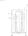
- the storage pack may be configured in such a manner that a plurality of storage modules, each of which comprises a plurality of storage devices connected in series, are connected in parallel, and the plurality of storage modules may include storage modules that are different from each other in the number of connected storage devices.
- the storage pack may include a plurality of kinds of storage modules having different kinds of storage devices.
- the charging/discharging curve of the storage pack can be provided with a step difference.
- a ratio of a capacity on the lower-SOC side than the start point of the step difference that the charging/discharging curve of the storage pack has to a capacity on the higher-SOC side than the end point of the step difference that the charging/discharging curve of the storage pack has is within a range of 10 : 90 to 90 : 10.
- the present invention can achieve cost reduction and scale reduction of a power supplying system.
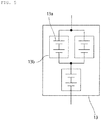
- FIG. 1 is a schematic circuit diagram of a power supplying system 1 according to the present embodiment.
- the power supplying system 1 shown in FIG. 1 includes a power supplying mechanism 10.
- the power supplying mechanism 10 is a mechanism that supplies a DC power.
- the power supplying mechanism 10 can be configured with, for example, various power generators such as a diesel power generator, a wind power generator, a nuclear power generator, a hydraulic power generator, a thermal power generator, a fuel cell, and a solar cell, an internal-combustion engine, or the like.
- the power supplying mechanism 10 may include a plurality of kinds of power generating mechanisms and the like.
- the power supplying mechanism 10 is configured with a power supplying unit 10a including a power generator or the like that supplies an AC power and a power conversion unit 10b that is connected to the power supplying unit 10a and having an AC-DC conversion function.
- the power supplying mechanism may be configured in such a manner that a power conversion unit having a DC-DC conversion function is further connected at a stage subsequent to the power conversion unit 10b having an AC-DC conversion function.
- the power supplying mechanism may be configured only with the power supplying unit, or alternatively, the power supplying mechanism 10 may be configured with the power supplying unit and a power conversion unit connected thereto and having a DC-DC conversion function.
- a rated voltage of the power supplying mechanism in the present application refers to the rated voltage of an output of the power supplying unit when the power supplying mechanism does not include a power conversion unit having an AC-DC conversion function, a power conversion unit having a DC-DC conversion function, or the like.
- the rated voltage of the power supplying mechanism refers to the rated voltage of an output of the last stage of these.
- the electric load 11 is connected to the power supplying mechanism 10.
- the electric load 11 is a mechanism that converts the electric power deriving from the power supplying mechanism 10 into energy other than electric power, such as a kinetic energy.
- the electric load 11 may be, for example, a motor of an automobile, a marine vessel, an aircraft, or the like, or an electric appliance used in general houses, public facilities, private facilities, and the like (for example, an air conditioner, a computer, a server, or the like).
- the electric load 11 when a main body of the electric load 11 is operated with an AC power as a driving force, the electric load 11 may include a power conversion unit having a DC-AC conversion function.
- the electric load 11 may include a power conversion unit having a DC-DC conversion function.
- the power supplying mechanism 10 and the electric load 11 are electrically connected with each other by a power line 12.
- a storage pack 13 is connected to the power line 12.
- a fuse, an FET (Field effect transistor) switch, or the like may be provided between the power line 12 and the storage pack 13 in accordance with the needs.
- the storage pack 13 may be connected to a controlling device for suppressing generation of abnormalities such as an overcharged state, overheating, and the like in accordance with the needs.
- the "storage pack” includes at least one kind of a storage device.
- a storage pack configured with at least one secondary battery is referred to as a "secondary battery pack".
- a lithium ion secondary battery pack means a secondary battery pack configured with at least one lithium ion secondary battery.
- a lead secondary battery pack means a secondary battery pack configured with at least one lead secondary battery.
- a nickel hydrogen secondary battery pack means a secondary battery pack configured with at least one nickel hydrogen secondary battery.
- the storage pack may be configured with one storage module.
- the storage pack may be configured with a plurality of storage modules that are connected in parallel.
- the storage pack may be one in which a storage module is connected in parallel to at least one of a plurality of storage modules that are connected in series.
- the "storage device” means a secondary battery such as a lead secondary battery, a lithium ion secondary battery, or a nickel hydrogen secondary battery, or a single cell such as a capacitor such as a lithium ion capacitor or an electric double-layer capacitor.
- the "storage module” means one or more storage devices that are connected in series. Accordingly, the storage pack may have a storage module.
- the plurality of storage devices when the storage pack has a plurality of storage devices, the plurality of storage devices may be of the same kind or may include a plurality of kinds of storage devices.
- the storage pack 13 is configured with one storage module 13b including a plurality of storage devices 13a that are connected in series.
- the storage pack 13 is configured with four lithium ion secondary battery devices 13a that are connected in series.
- the storage pack need not necessarily be configured with one storage module.
- a plurality of storage modules 13b may be connected in parallel in the storage pack 13.
- a storage module 13b may be connected in parallel to at least one of a plurality of storage modules 13b that are connected in series.
- a positive electrode active material contained in a positive electrode of the lithium ion secondary battery may be, for example, an inorganic compound such as a composite oxide of a transition metal and lithium, a transition metal oxide, or a transition metal sulfide, an organic compound, or the like.
- a compound obtained by replacing a transition metal element of the above inorganic compound with an element of different kind may be used as the positive electrode active material as well.
- These positive electrode active materials may be used either alone as one kind, or two or more kinds of positive electrode active materials may be simultaneously used.
- a negative electrode active material contained in a negative electrode of the lithium ion secondary battery may be, for example, an inorganic compound such as a composite oxide of a transition metal and lithium, a metal oxide, an alloy-based material, or a transition metal sulfide, a carbon material, an organic compound, lithium metal, or the like.
- an inorganic compound such as a composite oxide of a transition metal and lithium, a metal oxide, an alloy-based material, or a transition metal sulfide, a carbon material, an organic compound, lithium metal, or the like.
- the negative electrode active materials include composite oxides of transition metals and lithium such as LiMn 2 O 4 , Li 4 Ti 3 O 12 , Li 2 Ti 3 O 7 , LiMg 1/2 Ti 3/2 O 4 , LiCo 1/2 Ti 3/2 O 4 , LiZn 1/2 Ti 3/2 O 4 , LiFeTiO 4 , LiCrTiO 4 , Li 2 SrTi 6 O 14 , Li 2 BaTi 6 O 14 ; metal oxides such as TiO 2 , WO 3 , MoO 2 , MnO 2 , V 2 O 3 , SiO 2 , SiO, and SnO 2 ; alloy-based materials such as Si and Sn; transition metal sulfides such as FeS and TiS; carbon materials such as graphite, hardly graphitizable carbon, and easily graphitizable carbon; and organic compounds such as quinone compounds, disulfide compounds, diazine compounds, radialene compounds, rubeanic acid compounds, and organic radical compounds.
- a compound obtained by replacing a transition metal element of the above compound with an element of different kind may be used as the inorganic compound as well.
- These negative electrode active materials may be used either alone as one kind, or two or more kinds of negative electrode active materials may be simultaneously used. Further, a material obtained by subjecting the above negative electrode active material to a lithium ion pre-doping treatment may be used as the negative electrode active material as well.
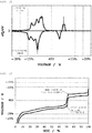
- FIG. 6 is a view describing a charging/discharging curve of the storage pack in the present embodiment.
- the charging/discharging curve of the storage pack 13 shown in FIG. 6 is a charging/discharging curve obtained when constant-current charging/discharging is performed at a current value of 0.2 C in an atmosphere of 25°C ⁇ 5°C within a voltage range from a discharging end voltage to a charging end voltage.
- the power supplying system 1 satisfies the following conditions (a), (b), and (c).
- the rated voltage represents the rated voltage of the power supplying mechanism 10
- Cha represents the charging curve of the storage pack 13
- Dis represents the discharging curve of the storage pack 13.
- the "step difference of the charging/discharging curve” refers to a range in which the voltage changes greatly within a range of SOC of the second storage pack being 5% or more and 95% or less.
- the “step difference of the charging/discharging curve” refers to a range in which the absolute value of ⁇ V/ ⁇ SOC, which is a ratio of the change of the voltage ( ⁇ V) of at least one of the charging curve and the discharging curve relative to the change of SOC ( ⁇ SOC), is (0.008 ⁇ rated voltage) V/% or more within a range of SOC being 5% or more and 95% or less.
- the rated voltage is the value (unit: V) of the rated voltage of the power supplying mechanism 10.
- start point of the step difference means the minimum voltage of the discharging curve within a range of one step difference and the SOC at that voltage.
- the "average discharging voltage on the lower-SOC side than the start point of the step difference” refers to an arithmetic average value of the voltage of the discharging curve within a range from the SOC being 0% to the SOC at the start point of the step difference.
- the "end point of the step difference” means the maximum voltage of the charging curve within a range of the same one step difference and the SOC at that voltage.
- the "average charging voltage on the higher-SOC side than the end point of the step difference” refers to an arithmetic average value of the voltage of the charging curve within a range from the SOC at the end point of the step difference to the SOC being 100%.
- the power supplying system 1 of the present embodiment satisfies all of the conditions (a), (b), (c), (d), and (e); however, the present invention is not limited thereto.
- the storage system according to the present invention may be configured to satisfy only the conditions (a), (b), and (c). Also, the storage system according to the present invention may be configured to satisfy only the conditions (a), (d), and (e).
- the power supplying system 1 satisfies the condition (a). For this reason, the voltage of the storage pack 13 is almost equal to the rated voltage of the power supplying mechanism 10 in the step difference that the charging/discharging curve of the storage pack 13 has. Accordingly, little electric current flows through the storage pack 13. Thus, there is not necessarily a need to provide a controlling device for monitoring or controlling the SOC of the storage pack 13 in order to keep the SOC of the storage pack 13 in an almost constant state. Also, the capacity required in the storage pack 13 can be reduced. Therefore, cost reduction and scale reduction of the power supplying system 1 can be achieved. Further, the frequency of charging/discharging of the storage pack 13 can be reduced.
- the power supplying system 1 satisfies at least one of the conditions (b) and (d). For this reason, discharging occurs from the storage pack 13 to the electric load 11 when the voltage of the electric power that is supplied from the power supplying mechanism 10 comes to be lower than the voltage that the electric load 11 needs due to decrease in the amount of power supply from the power supplying mechanism 10 or increase in the power consumption of the electric load 11. Also, for example, when the power supply from the power supplying mechanism 10 stops, discharging occurs from the storage pack 13 to the electric load 11. This can suppress a situation in which the voltage of the electric power supplied to the electric load 11 comes to be lower than -20% of the rated voltage of the power supplying mechanism 10.
- the power supplying system 1 preferably satisfies at least one of the following conditions (b1) and (d1).
- the power supplying system 1 satisfies at least one of the conditions (c) and (e). For this reason, charging occurs from the electric load 11 to the storage pack 13 when the voltage of the electric power that is supplied from the power supplying mechanism 10 comes to be higher than the voltage that the electric load 11 needs due to increase in the amount of power supply from the power supplying mechanism 10 or decrease in the power consumption of the electric load 11. Also, for example, when the electric load 11 has a motor and regenerated energy is produced from the motor, charging occurs from the electric load 11 to the storage pack 13. This can suppress a situation in which the voltage of the electric power supplied to the electric load 11 comes to be higher than +20% of the rated voltage of the power supplying mechanism 10.
- the power supplying system 1 preferably satisfies at least one of the following conditions (c1) and (e1).
- the average discharging voltage on the lower-SOC side than the start point of the step difference that the charging/discharging curve of the storage pack 13 has is -2% or less of the rated voltage. In this case, frequency of charging/discharging of the storage pack 13 can be reduced, and also degradation caused by charging/discharging of the storage pack 13 can be prevented, so that the lifetime of the power supplying system 1 can be prolonged.
- the voltage of the peak top on the curve (dQ/dV curve) obtained by differentiating the discharging curve of the storage pack 13 with respect to the voltage on the lower-SOC side than the start point of the step difference that the charging/discharging curve of the storage pack 13 has is -2% or less of the rated voltage.
- the average charging voltage on the higher-SOC side than the end point of the step difference that the charging/discharging curve of the storage pack 13 has is +2% or more of the rated voltage. In this case, frequency of charging/discharging of the storage pack 13 can be reduced, and also degradation caused by charging/discharging of the storage pack 13 can be prevented, so that the lifetime of the power supplying system can be prolonged.
- the voltage of the peak top on the curve (dQ/dV curve) obtained by differentiating the charging curve of the storage pack 13 with respect to the voltage on the higher-SOC side than the end point of the step difference that the charging/discharging curve of the storage pack 13 has is +2% or more of the rated voltage.
- the following methods can be considered as a method for allowing the power supplying system 1 to satisfy the conditions (a), (b), (c), (d), and (e).
- the storage pack 13 is configured as a lithium ion secondary battery pack having a lithium ion secondary battery
- the positive electrode of the lithium ion secondary battery is configured by using a positive electrode active material that allows the charging/discharging curve of the lithium ion secondary battery to have a step difference
- the negative electrode of the lithium ion secondary battery is configured by using a negative electrode active material that allows the charging/discharging curve of the lithium ion secondary battery to have a step difference.
- These positive electrode active materials may be used either alone as one kind or by mixing a plurality of kinds of these.
- the storage pack 13 is configured as a lithium ion secondary battery pack having a lithium ion secondary battery, and the positive electrode of the lithium ion secondary battery is allowed to contain a plurality of kinds of positive electrode active materials.
- the following positive electrode active materials into the positive electrode of the lithium ion secondary battery.
- the storage pack 13 is configured as a lithium ion secondary battery pack having a lithium ion secondary battery, and the negative electrode of the lithium ion secondary battery is allowed to contain a plurality of kinds of negative electrode active materials.
- the storage pack 13 is configured with a plurality of storage devices of one kind and is configured with storage modules that are connected in parallel and different from each other in the number of connected storage devices.
- the storage pack 13 is configured with a plurality of kinds of storage modules having different kinds of storage devices.
- lithium ion secondary batteries containing different positive electrode active materials may be considered to incorporate lithium ion secondary batteries containing different positive electrode active materials into the storage pack 13, as shown in the following 1) to 8).
- At least two kinds of storage modules selected from the group consisting of a lithium ion secondary battery module, a nickel hydrogen secondary battery module, a lead secondary battery module, and a capacitor may be incorporated into the storage pack 13.
- the storage pack 13 is configured with a plurality of storage modules connected in parallel and having voltages that are different from each other, a switch disposed in at least one of the storage modules, and a controlling unit that turns on/off the switch.
- a step difference is formed in the charging/discharging curve by on/off of the switch.
- the switch is preferably provided in a storage module having a relatively low voltage.
- the step difference can be formed in the charging/discharging curve by turning off the switch before the storage module provided with the switch is overly charged.
- the step difference can be formed in the charging/discharging curve by turning off the switch before the storage module provided with the switch is overly discharged.
- a ratio of a capacity on the lower-SOC side than the start point of the step difference that the charging/discharging curve of the storage pack 13 has to a capacity on the higher-SOC side than the end point of the step difference that the charging/discharging curve of the storage pack 13 has is within a range of 10 : 90 to 90 : 10.
- both of voltage fall and overvoltage of the electric power supplied to the electric load 11 can be further prevented by the storage pack 13, so that further cost reduction and scale reduction of the power supplying system 1 can be achieved.
- a power supplying mechanism 10 having a rated voltage of 48 V was configured with a power source of three-phase AC 200 V as a power supplying unit 10a and an AC-DC converter that converts the electric power of three-phase AC 200 V into the electric power of DC 48 V as a power conversion unit 10b having an AC-DC conversion function.
- this power supplying mechanism 10 and a storage module having a configuration described below as a storage pack 13 a power supplying system 1 according to the above embodiment was constructed.
- Li[Ni 0.25 Mn 1.75 ]O 4 as a positive electrode active material and graphite as a negative electrode active material
- a lithium ion secondary battery having an A/C ratio of 1.2 and a capacity of 10 Ah was prepared.
- a storage pack 13 a storage module was prepared in which 11 lithium ion secondary batteries thus formed were connected in series.
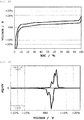
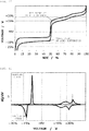
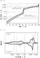
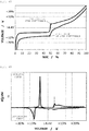
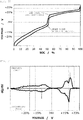
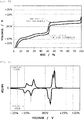
- FIG. 8 shows a charging/discharging curve of the storage pack 13 prepared in the present Example
- FIG. 9 shows a curve (dQ/dV curve) obtained by differentiating the charging/discharging curve of the storage pack 13 with respect to the voltage.
- a power supplying system 1 was constructed in the same manner as in Example 1 except that a storage module in which 11 lithium ion secondary batteries thus prepared were connected in series was used as a storage pack 13.
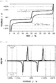
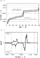
- FIG. 10 shows a charging/discharging curve of the storage pack 13 prepared in the present Example
- FIG. 11 shows a curve (dQ/dV curve) obtained by differentiating the charging/discharging curve of the storage pack 13 with respect to the voltage.
- a power supplying system 1 was constructed in the same manner as in Example 1 except that a storage module in which 11 lithium ion secondary batteries thus prepared were connected in series was used as a storage pack 13.
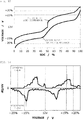
- FIG. 12 shows a charging/discharging curve of the storage pack 13 prepared in the present Example
- FIG. 13 shows a curve (dQ/dV curve) obtained by differentiating the charging/discharging curve of the storage pack 13 with respect to the voltage.
- a power supplying system 1 was constructed in the same manner as in Example 1 except that a storage module in which 11 lithium ion secondary batteries thus prepared were connected in series was used as a storage pack 13.
- FIG. 14 shows a charging/discharging curve of this storage pack 13
- FIG. 15 shows a curve (dQ/dV curve) obtained by differentiating the charging/discharging curve of the storage pack 13 with respect to the voltage.
- a power supplying system 1 was constructed in the same manner as in Example 1 except that a storage module in which 11 lithium ion secondary batteries thus prepared were connected in series was used as a storage pack 13.
- FIG. 16 shows a charging/discharging curve of this storage pack 13
- FIG. 17 shows a curve (dQ/dV curve) obtained by differentiating the charging/discharging curve of the storage pack 13 with respect to the voltage.
- a lithium ion secondary battery having an A/C ratio of 1.2 and a capacity of 10 Ah was prepared.
- a power supplying system 1 was constructed in the same manner as in Example 1 except that a storage module in which 12 lithium ion secondary batteries thus prepared were connected in series was used as a storage pack 13.
- FIG. 18 shows a charging/discharging curve of this storage pack 13
- FIG. 19 shows a curve (dQ/dV curve) obtained by differentiating the charging/discharging curve of the storage pack 13 with respect to the voltage.
- Li[Ni 0.50 Mn 1.50 ]O 4 as a positive electrode active material and graphite as a negative electrode active material
- a lithium ion secondary battery having an A/C ratio of 1.2 and a capacity of 10 Ah was prepared.
- a power supplying system 1 was constructed in the same manner as in Example 1 except that a storage module in which 11 lithium ion secondary batteries thus prepared were connected in series was used as a storage pack 13.
- FIG. 20 shows a charging/discharging curve of this storage pack 13
- FIG. 21 shows a curve (dQ/dV curve) obtained by differentiating the charging/discharging curve of the storage pack 13 with respect to the voltage.
- a power supplying system 1 was constructed in the same manner as in Example 1 except that a storage module in which 12 lithium ion secondary batteries thus prepared were connected in series was used as a storage pack 13.
- FIG. 22 shows a charging/discharging curve of this storage pack 13
- FIG. 23 shows a curve (dQ/dV curve) obtained by differentiating the charging/discharging curve of the storage pack 13 with respect to the voltage.
- a power supplying system 1 was constructed in the same manner as in Example 1 except that a storage module in which 12 lithium ion secondary batteries thus prepared were connected in series was used as a storage pack 13.
- FIG. 24 shows a charging/discharging curve of this storage pack 13
- FIG. 25 shows a curve (dQ/dV curve) obtained by differentiating the charging/discharging curve of the storage pack 13 with respect to the voltage.
- a power supplying system 1 was constructed in the same manner as in Example 1 except that a storage module in which 12 lithium ion secondary batteries thus prepared were connected in series was used as a storage pack 13.
- FIG. 26 shows a charging/discharging curve of this storage pack 13
- FIG. 27 shows a curve (dQ/dV curve) obtained by differentiating the charging/discharging curve of the storage pack 13 with respect to the voltage.
- Table 1 shows the rated voltage, the configuration of the storage pack 13, the SOC and voltage at the start point of the step difference, the SOC and voltage at the end point of the step difference, the average discharging voltage and the voltage of the peak top on the dQ/dV curve on the lower-SOC side than the start point of the step difference, the average charging voltage and the voltage of the peak top on the dQ/dV curve on the higher-SOC side than the end point of the step difference, and the ratio of a capacity on the lower-SOC side than the start point of the step difference to a capacity on the higher-SOC side than the end point of the step difference in each of the Examples and Reference Examples.
- a storage pack 13 can be designed satisfying at least one of the above conditions (a), (b), (c) and conditions (a), (d), (e) by using Li[Ni x Mn (2-x) ]O 4 (0.05 ⁇ x ⁇ 0.40) which is a positive electrode active material having a step difference in the charging/discharging curve.
- the positions of the start point of the step difference and the end point of the step difference can be easily adjusted by adjusting the value of x and the synthesis conditions in the active material composition and, by this, the ratio of the capacity on the lower-SOC side than the start point of the step difference to the capacity on the higher-SOC side than the end point of the step difference can be easily adjusted.
- the positions of the start point of the step difference and the end point of the step difference can be adjusted also by adding an element of different kind (for example, Li, Ti, Al, Mg, B, Cr, Co, or the like) or replacing Ni or Mn with an element of different kind besides the value of x and the synthesis conditions.
- an element of different kind for example, Li, Ti, Al, Mg, B, Cr, Co, or the like
- LiMn 2 O 4 Li[Ni 0.5 Mn 1.5 ]O 4 in a weight ratio (LiMn 2 O 4 : Li[Ni 0.5 Mn 1.5 ]O 4 ) of 60 : 40 as a positive electrode active material and graphite as a negative electrode active material
- a lithium ion secondary battery having an A/C ratio of 1.2 and a capacity of 10 Ah was prepared.
- a power supplying system 1 was constructed in the same manner as in Example 1 except that a storage module in which 11 lithium ion secondary batteries thus prepared were connected in series was used as a storage pack 13.
- FIG. 28 shows a charging/discharging curve of this storage pack 13
- FIG. 29 shows a curve (dQ/dV curve) obtained by differentiating the charging/discharging curve of the storage pack 13 with respect to the voltage.
- LiFePO 4 LiNi 1/3 Co 1/3 Mn 1/3 O 2 in a weight ratio (LiFePO 4 : LiNi 1/3 Co 1/3 Mn 1/3 O 2 ) of 35 : 65 as a positive electrode active material and Si as a negative electrode active material
- a lithium ion secondary battery having an A/C ratio of 3.0 and a capacity of 10 Ah was prepared.
- a power supplying system 1 was constructed in the same manner as in Example 1 except that a storage module in which 16 lithium ion secondary batteries thus prepared were connected in series was used as a storage pack 13.
- FIG. 30 shows a charging/discharging curve of this storage pack 13
- FIG. 31 shows a curve (dQ/dV curve) obtained by differentiating the charging/discharging curve of the storage pack 13 with respect to the voltage.
- LiFePO 4 LiNi 1/3 Co 1/3 Mn 1/3 O 2
- Li 4 Ti 5 O 12 Li 4 Ti 5 O 12 as a negative electrode active material
- a power supplying system 1 was constructed in the same manner as in Example 1 except that a storage module in which 24 lithium ion secondary batteries thus prepared were connected in series was used as a storage pack 13.
- FIG. 32 shows a charging/discharging curve of this storage pack 13
- FIG. 33 shows a curve (dQ/dV curve) obtained by differentiating the charging/discharging curve of the storage pack 13 with respect to the voltage.
- a storage pack 13 can be designed satisfying at least one of the above conditions (a), (b), (c) and conditions (a), (d), (e) by using a plurality of kinds of positive electrode active materials. Also, the positions of the start point and end point of the step difference of the charging/discharging curve can be easily adjusted by adjusting the mixing ratio of the positive electrode active materials. By this, the ratio of the capacity on the lower-SOC side than the start point of the step difference to the capacity on the higher-SOC side than the end point of the step difference can be easily adjusted.
- a lithium ion secondary battery having an A/C ratio of 1.2 and a capacity of 6 Ah was prepared.
- a first storage module was prepared in which 11 lithium ion secondary batteries thus prepared were connected in series.
- a lithium ion secondary battery having an A/C ratio of 1.2 and a capacity of 4 Ah was prepared.
- a second storage module was prepared in which 11 lithium ion secondary batteries thus prepared were connected in series.
- a storage pack 13 was prepared by connecting the first storage module and the second storage module in parallel.
- a power supplying system 1 was constructed in the same manner as in Example 1 except that this storage pack 13 was used.
- the charging/discharging curve of the storage pack 13 prepared in Example 12 is similar to the charging/discharging curve of the storage pack 13 prepared in Example 9.
- the dQ/dV curve of the storage pack 13 prepared in Example 12 is similar to the dQ/dV curve of the storage pack 13 prepared in Example 9.
- LiFePO 4 as a positive electrode active material and Li 4 Ti 5 O 12 as a negative electrode active material
- a lithium ion secondary battery having an A/C ratio of 0.8 and a capacity of 5 Ah was prepared.
- a first storage module was assembled in which 24 lithium ion secondary batteries thus prepared were connected in series.
- a second storage module was assembled in which 28 lithium ion secondary batteries thus prepared were connected in series.
- a storage pack 13 was prepared by connecting the first storage module and the second storage module in parallel.
- a power supplying system 1 was constructed in the same manner as in Example 1 except that this storage pack 13 was used.
- FIG. 34 shows a charging/discharging curve of this storage pack 13
- FIG. 35 shows a curve (dQ/dV curve) obtained by differentiating the charging/discharging curve of the storage pack 13 with respect to the voltage.
- a storage pack 13 can be designed satisfying at least one of the above conditions (a), (b), (c) and conditions (a), (d), (e) by connecting in parallel a plurality of storage modules that are different from each other in the number of secondary batteries connected in series. Also, when the capacity ratio of the two storage modules is changed, the positions of the start point of the step difference and the end point of the step difference can be adjusted and, by this, the ratio of the capacity on the lower-SOC side than the start point of the step difference to the capacity on the higher-SOC side than the end point of the step difference can be adjusted.
- LiFePO 4 Li[Ni 0.50 Mn 1.50 ]O 4 in a weight ratio (LiFePO 4 : Li[Ni 0.50 Mn 1.50 ]O 4 ) of 50 : 50 as a positive electrode active material and hard carbon as a negative electrode active material
- a lithium ion secondary battery having an A/C ratio of 1.5 and a capacity of 10 Ah was prepared.
- a power supplying system 1 was constructed in the same manner as in Example 1 except that a storage module in which 13 lithium ion secondary batteries thus prepared were connected in series was used as a storage pack 13.
- FIG. 36 shows a charging/discharging curve of this storage pack 13
- FIG. 37 shows a curve (dQ/dV curve) obtained by differentiating the charging/discharging curve of the storage pack 13 with respect to the voltage.
- LiFePO 4 LiFePO 4 : LiMn 2 O 4
- a lithium ion secondary battery having an A/C ratio of 1.2 and a capacity of 10 Ah was prepared.
- a power supplying system 1 was constructed in the same manner as in Example 1 except that a storage module in which 21 lithium ion secondary batteries thus prepared were connected in series was used as a storage pack 13.
- FIG. 38 shows a charging/discharging curve of this storage pack 13
- FIG. 39 shows a curve (dQ/dV curve) obtained by differentiating the charging/discharging curve of the storage pack 13 with respect to the voltage.
- LiFePO 4 LiFePO 4 : LiMn 2 O 4
- a lithium ion secondary battery having an A/C ratio of 1.2 and a capacity of 10 Ah was prepared.
- a power supplying system 1 was constructed in the same manner as in Example 1 except that a storage module in which 23 lithium ion secondary batteries thus prepared were connected in series was used as a storage pack 13.
- FIG. 40 shows a charging/discharging curve of this storage pack 13
- FIG. 41 shows a curve (dQ/dV curve) obtained by differentiating the charging/discharging curve of the storage pack 13 with respect to the voltage.
- a power supplying system 1 was constructed in the same manner as in Example 1 except that a storage module in which 9 lithium ion secondary batteries thus prepared were connected in series was used as a storage pack 13.
- FIG. 42 shows a charging/discharging curve of this storage pack 13
- FIG. 43 shows a curve (dQ/dV curve) obtained by differentiating the charging/discharging curve of the storage pack 13 with respect to the voltage.
- a power supplying system 1 was constructed in the same manner as in Example 1 except that a storage module in which 13 lithium ion secondary batteries thus prepared were connected in series was used as a storage pack 13.
- FIG. 44 shows a charging/discharging curve of this storage pack 13
- FIG. 45 shows a curve (dQ/dV curve) obtained by differentiating the charging/discharging curve of the storage pack 13 with respect to the voltage.
- a power supplying system 1 was constructed in the same manner as in Example 1 except that a storage module in which 11 lithium ion secondary batteries thus prepared were connected in series was used as a storage pack 13.
- the charging/discharging curve of the storage pack 13 prepared in Example 14 is similar to the charging/discharging curve of the storage pack 13 prepared in Example 1.
- the dQ/dV curve of the storage pack 13 prepared in Example 14 is similar to the dQ/dV curve of the storage pack 13 prepared in Example 1.
- Li[Ni 0.25 Mn 1.75 ]O 4 as a positive electrode active material and graphite as a negative electrode active material a lithium ion secondary battery having an A/C ratio of 1.2 and a capacity of 50 Ah was prepared.
- a storage module was assembled by connecting 11 lithium ion secondary batteries thus prepared in series.
- a storage pack 13 was assembled by connecting two storage modules thus prepared in parallel.
- a power supplying system 1 was constructed in the same manner as in Example 1 except for the above.
- the charging/discharging curve of the storage pack 13 prepared in Example 15 is similar to the charging/discharging curve of the storage pack 13 prepared in Example 1.
- the dQ/dV curve of the storage pack 13 prepared in Example 15 is similar to the dQ/dV curve of the storage pack 13 prepared in Example 1.
- Li[Ni 0.25 Mn 1.75 ]O 4 as a positive electrode active material and graphite as a negative electrode active material a lithium ion secondary battery having an A/C ratio of 1.2 and a capacity of 50 Ah was prepared.
- a storage module was assembled by connecting 11 lithium ion secondary batteries thus prepared in series.
- a storage pack 13 was assembled by connecting 20 storage modules thus prepared in parallel.
- a power supplying system 1 was constructed in the same manner as in Example 1 except for the above.
- the charging/discharging curve of the storage pack 13 prepared in Example 16 is similar to the charging/discharging curve of the storage pack 13 prepared in Example 1.
- the dQ/dV curve of the storage pack 13 prepared in Example 16 is similar to the dQ/dV curve of the storage pack 13 prepared in Example 1.
- Li[Ni 0.25 Mn 1.75 ]O 4 as a positive electrode active material and hard carbon as a negative electrode active material a lithium ion secondary battery having an A/C ratio of 1.2 and a capacity of 10 Ah was prepared.
- a storage pack 13 a storage module was prepared in which three lithium ion secondary batteries thus formed were connected in series.
- FIG. 46 shows a charging/discharging curve of this storage pack 13
- FIG. 47 shows a curve (dQ/dV curve) obtained by differentiating the charging/discharging curve of the storage pack 13 with respect to the voltage.
- the storage pack 13 prepared in the present Example 17 can be suitably used in the power supplying system 1 having a power supplying mechanism 10 with the rated voltage of DC 12 V.
- LiFePO 4 LiNi 1/3 Co 1/3 Mn 1/3 O 2
- Li 4 Ti 5 O 12 Li 4 Ti 5 O 12 as a negative electrode active material
- a lithium ion secondary battery having an A/C ratio of 1.2 and a capacity of 10 Ah was prepared.
- a storage pack 13 a storage module was prepared in which 7 lithium ion secondary batteries thus formed were connected in series.
- FIG. 48 shows a charging/discharging curve of this storage pack 13
- FIG. 49 shows a curve (dQ/dV curve) obtained by differentiating the charging/discharging curve of the storage pack 13 with respect to the voltage.
- the storage pack prepared in Example 18 can be suitably used in the power supplying system 1 having a power supplying mechanism 10 with the rated voltage of DC 14.4 V.
- Li[Ni 0.25 Mn 1.75 ]O 4 as a positive electrode active material and hard carbon as a negative electrode active material a lithium ion secondary battery having an A/C ratio of 1.2 and a capacity of 10 Ah was prepared.
- a storage pack 13 a storage module was prepared in which 6 lithium ion secondary batteries thus formed were connected in series.
- FIG. 50 shows a charging/discharging curve of this storage pack 13
- FIG. 51 shows a curve (dQ/dV curve) obtained by differentiating the charging/discharging curve of the storage pack 13 with respect to the voltage.
- the storage pack prepared in Example 19 can be suitably used in the power supplying system 1 having a power supplying mechanism 10 with the rated voltage of DC 24 V.
- Li[Ni 0.25 Mn 1.75 ]O 4 as a positive electrode active material and graphite as a negative electrode active material
- a lithium ion secondary battery having an A/C ratio of 1.2 and a capacity of 10 Ah was prepared.
- a storage pack 13 a storage module was prepared in which 86 lithium ion secondary batteries thus formed were connected in series.
- FIG. 52 shows a charging/discharging curve of this storage pack 13
- FIG. 53 shows a curve (dQ/dV curve) obtained by differentiating the charging/discharging curve of the storage pack 13 with respect to the voltage.
- the storage pack prepared in Example 20 can be suitably used in the power supplying system 1 having a power supplying mechanism 10 with the rated voltage of DC 380 V.
- Li[Ni 0.25 Mn 1.75 ]O 4 as a positive electrode active material and hard carbon as a negative electrode active material a lithium ion secondary battery having an A/C ratio of 1.2 and a capacity of 50 Ah was prepared.
- a storage pack 13 a storage module was prepared in which 345 lithium ion secondary batteries thus formed were connected in series.
- FIG. 54 shows a charging/discharging curve of this storage pack 13
- FIG. 55 shows a curve (dQ/dV curve) obtained by differentiating the charging/discharging curve of the storage pack 13 with respect to the voltage.
- the storage pack prepared in Example 21 can be suitably used in the power supplying system 1 having a power supplying mechanism 10 with the rated voltage of DC 1500 V.
- a nickel hydrogen secondary battery having a capacity of 5 Ah was used as a storage device 13a.
- a first storage module 13b1 was prepared by connecting 8 nickel hydrogen secondary batteries thus formed in series.
- a second storage module 13b2 was prepared by connecting 10 nickel hydrogen secondary batteries thus formed in series.
- a storage pack 13 was prepared by connecting the first storage module 13b1 and the second storage module 13b2 in parallel and disposing a switch 14 on the first storage module 13b1 side. The switch 14 is turned on when the voltage of the first storage module 13b1 is 12.0 V or lower and is turned off when the voltage is higher than 12.0 V.
- FIG. 57 shows a charging/discharging curve of this storage pack 13
- FIG. 58 shows a curve (dQ/dV curve) obtained by differentiating the charging/discharging curve of the storage pack 13 with respect to the voltage.
- the storage pack prepared in Example 22 can be suitably used in the power supplying system 1 having a power supplying mechanism 10 with the rated voltage of DC 12 V.
- a step difference can be formed in the charging/discharging curve by providing a switch 14 that is turned on/off at a certain voltage in the storage pack 13. Also, by providing the switch, the storage module having the lower charging/discharging voltage can be prevented from being brought into an overcharged state, and the storage module having the higher charging/discharging voltage can be prevented from being brought into an overly discharged state. For this reason, a nickel hydrogen secondary battery or a lithium ion secondary battery having a low overcharging resistance can be used in the storage pack 13. Accordingly, the storage pack 13 prevents the voltage of the first storage pack 11 from entering an overcharged region or an overly discharged region.
Landscapes
- Chemical & Material Sciences (AREA)
- Chemical Kinetics & Catalysis (AREA)
- Electrochemistry (AREA)
- General Chemical & Material Sciences (AREA)
- Engineering & Computer Science (AREA)
- Manufacturing & Machinery (AREA)
- Inorganic Chemistry (AREA)
- Power Engineering (AREA)
- Composite Materials (AREA)
- Microelectronics & Electronic Packaging (AREA)
- Crystallography & Structural Chemistry (AREA)
- Materials Engineering (AREA)
- Charge And Discharge Circuits For Batteries Or The Like (AREA)
- Secondary Cells (AREA)
- Battery Electrode And Active Subsutance (AREA)
Applications Claiming Priority (2)
| Application Number | Priority Date | Filing Date | Title |
|---|---|---|---|
| JP2015190932 | 2015-09-29 | ||
| PCT/JP2016/078292 WO2017057283A1 (fr) | 2015-09-29 | 2016-09-26 | Système d'alimentation électrique |
Publications (3)
| Publication Number | Publication Date |
|---|---|
| EP3358706A1 true EP3358706A1 (fr) | 2018-08-08 |
| EP3358706A4 EP3358706A4 (fr) | 2019-05-15 |
| EP3358706B1 EP3358706B1 (fr) | 2020-07-08 |
Family
ID=58423560
Family Applications (1)
| Application Number | Title | Priority Date | Filing Date |
|---|---|---|---|
| EP16851454.5A Active EP3358706B1 (fr) | 2015-09-29 | 2016-09-26 | Système de stabilisation d'alimentation électrique |
Country Status (5)
| Country | Link |
|---|---|
| US (1) | US10547202B2 (fr) |
| EP (1) | EP3358706B1 (fr) |
| JP (1) | JP6375549B2 (fr) |
| CN (1) | CN108141059B (fr) |
| WO (1) | WO2017057283A1 (fr) |
Cited By (4)
| Publication number | Priority date | Publication date | Assignee | Title |
|---|---|---|---|---|
| EP4044287A4 (fr) * | 2020-12-24 | 2022-12-28 | Contemporary Amperex Technology Co., Limited | Module de batterie, et procédé de fabrication et dispositif associés, et bloc-batterie et appareil électrique |
| US11901555B2 (en) | 2021-07-30 | 2024-02-13 | Contemporary Amperex Technology Co., Limited | Battery module, battery pack, and electric apparatus |
| US11990592B2 (en) | 2020-11-17 | 2024-05-21 | Contemporary Amperex Technology Co., Limited | Battery, apparatus using battery, and manufacturing method and manufacturing device of battery |
| US12034176B2 (en) | 2020-09-30 | 2024-07-09 | Contemporary Amperex Technology Co., Limited | Battery, apparatus, and preparation method and preparation apparatus of battery |
Families Citing this family (5)
| Publication number | Priority date | Publication date | Assignee | Title |
|---|---|---|---|---|
| KR102563753B1 (ko) * | 2017-12-29 | 2023-08-04 | 삼성전자주식회사 | 배터리 충전 방법 및 장치 |
| KR102349300B1 (ko) | 2018-04-10 | 2022-01-10 | 주식회사 엘지에너지솔루션 | 배터리의 전극 정보를 결정하기 위한 장치, 방법, 배터리 팩 및 전기 시스템 |
| JP7214993B2 (ja) * | 2018-06-29 | 2023-01-31 | 株式会社リコー | 蓄電システム |
| CN109768341A (zh) * | 2019-01-14 | 2019-05-17 | 湖南科霸汽车动力电池有限责任公司 | 镍氢电池、锂电池通用的电池管理系统及其管理方法 |
| JP7326229B2 (ja) * | 2020-07-22 | 2023-08-15 | 株式会社東芝 | 蓄電池 |
Family Cites Families (14)
| Publication number | Priority date | Publication date | Assignee | Title |
|---|---|---|---|---|
| JPH03121660U (fr) * | 1990-03-26 | 1991-12-12 | ||
| US5606242A (en) * | 1994-10-04 | 1997-02-25 | Duracell, Inc. | Smart battery algorithm for reporting battery parameters to an external device |
| CN1163020A (zh) * | 1994-10-04 | 1997-10-22 | 杜拉塞奥公司 | 用于向外部设备报告电池参数的智能电池算法 |
| US5633573A (en) * | 1994-11-10 | 1997-05-27 | Duracell, Inc. | Battery pack having a processor controlled battery operating system |
| US20040224229A1 (en) * | 2003-05-09 | 2004-11-11 | Mansuetto Michael F. | Alkaline cell with copper oxide cathode |
| CN100433447C (zh) * | 2004-09-24 | 2008-11-12 | 株式会社东芝 | 蓄电系统、再生蓄电系统和汽车 |
| JP4314223B2 (ja) * | 2004-09-24 | 2009-08-12 | 株式会社東芝 | 回生用蓄電システム、蓄電池システムならびに自動車 |
| JP2006338889A (ja) * | 2005-05-31 | 2006-12-14 | Matsushita Electric Ind Co Ltd | 電力管理システムおよび電力システム管理方法 |
| EP2737565B1 (fr) * | 2011-07-25 | 2019-09-25 | A123 Systems LLC | Matières mélangées pour cathodes |
| US9360527B2 (en) * | 2011-08-12 | 2016-06-07 | Johnson Controls Technology Llc | System and method for energy prediction in battery packs |
| JP2014233098A (ja) | 2011-09-27 | 2014-12-11 | 三洋電機株式会社 | 充放電システム |
| JP6000742B2 (ja) * | 2012-08-10 | 2016-10-05 | シャープ株式会社 | パワーコンディショナおよび電力供給システム |
| CN104319425B (zh) * | 2014-08-25 | 2016-06-22 | 江苏华东锂电技术研究院有限公司 | 对锂离子电池的容量进行管理的方法 |
| CN104319426B (zh) * | 2014-08-25 | 2016-06-22 | 江苏华东锂电技术研究院有限公司 | 对锂离子电池的容量进行管理的方法 |
-
2016
- 2016-09-26 WO PCT/JP2016/078292 patent/WO2017057283A1/fr unknown
- 2016-09-26 CN CN201680056541.3A patent/CN108141059B/zh active Active
- 2016-09-26 JP JP2017543263A patent/JP6375549B2/ja active Active
- 2016-09-26 EP EP16851454.5A patent/EP3358706B1/fr active Active
-
2018
- 2018-03-19 US US15/925,085 patent/US10547202B2/en active Active
Cited By (5)
| Publication number | Priority date | Publication date | Assignee | Title |
|---|---|---|---|---|
| US12034176B2 (en) | 2020-09-30 | 2024-07-09 | Contemporary Amperex Technology Co., Limited | Battery, apparatus, and preparation method and preparation apparatus of battery |
| US11990592B2 (en) | 2020-11-17 | 2024-05-21 | Contemporary Amperex Technology Co., Limited | Battery, apparatus using battery, and manufacturing method and manufacturing device of battery |
| EP4044287A4 (fr) * | 2020-12-24 | 2022-12-28 | Contemporary Amperex Technology Co., Limited | Module de batterie, et procédé de fabrication et dispositif associés, et bloc-batterie et appareil électrique |
| US12068468B2 (en) | 2020-12-24 | 2024-08-20 | Contemporary Amperex Technology Co., Limited | Battery module and manufacturing method and device thereof, battery pack, and power consumption apparatus |
| US11901555B2 (en) | 2021-07-30 | 2024-02-13 | Contemporary Amperex Technology Co., Limited | Battery module, battery pack, and electric apparatus |
Also Published As
| Publication number | Publication date |
|---|---|
| CN108141059B (zh) | 2021-09-07 |
| JPWO2017057283A1 (ja) | 2018-06-07 |
| CN108141059A (zh) | 2018-06-08 |
| US10547202B2 (en) | 2020-01-28 |
| EP3358706A4 (fr) | 2019-05-15 |
| EP3358706B1 (fr) | 2020-07-08 |
| US20180212458A1 (en) | 2018-07-26 |
| WO2017057283A1 (fr) | 2017-04-06 |
| JP6375549B2 (ja) | 2018-08-22 |
Similar Documents
| Publication | Publication Date | Title |
|---|---|---|
| EP3358706B1 (fr) | Système de stabilisation d'alimentation électrique | |
| Hu et al. | Technological developments in batteries: a survey of principal roles, types, and management needs | |
| EP2108202B1 (fr) | Batterie secondaire à sécurité améliorée | |
| US10780793B2 (en) | Power storage system, transfer mechanism, transport mechanism, vehicle, and automobile | |
| US20150050527A1 (en) | Dual storage system and method with lithium ion and lead acid battery cells | |
| US10720676B2 (en) | Power storage pack having first and second power storage packs connected in parallel | |
| EP2983000A1 (fr) | Dispositif et système de stockage d'électricité et véhicule électrique | |
| KR20080073220A (ko) | 전지 유닛 | |
| JP2009080939A (ja) | 電源システムおよび電池集合体の制御方法 | |
| CN101582517A (zh) | 一种充放电池组及其控制方法 | |
| JP2009080938A (ja) | 電源システムおよび電池集合体の制御方法 | |
| JP7131124B2 (ja) | 組電池、車両、および組電池の製造方法 | |
| Al-Karakchi et al. | Smart EV charging profiles to extend battery life | |
| JP2021023018A (ja) | 車載用電源システム | |
| JP5705046B2 (ja) | 電源システム | |
| US12068466B2 (en) | Battery heating system and method, power supply system, and electrical apparatus | |
| WO2014184861A1 (fr) | Système de batterie, corps mobile et système de stockage d'énergie doté d'un système de batterie, et procédé de commande du système de batterie | |
| WO2016080222A1 (fr) | Batterie embarquée, et dispositif d'alimentation électrique embarqué | |
| US20240063370A1 (en) | Dual-cation metal battery and charging and discharging method thereof | |
| Hnatova | Justification of the importance of improving the battery management system in electric vehicles | |
| CN116613399A (zh) | 一种分容方法及电池 | |
| UA155218U (uk) | Балансуючий зарядний пристрій для літій-іонних акумуляторних батарей |
Legal Events
| Date | Code | Title | Description |
|---|---|---|---|
| STAA | Information on the status of an ep patent application or granted ep patent |
Free format text: STATUS: THE INTERNATIONAL PUBLICATION HAS BEEN MADE |
|
| PUAI | Public reference made under article 153(3) epc to a published international application that has entered the european phase |
Free format text: ORIGINAL CODE: 0009012 |
|
| STAA | Information on the status of an ep patent application or granted ep patent |
Free format text: STATUS: REQUEST FOR EXAMINATION WAS MADE |
|
| 17P | Request for examination filed |
Effective date: 20180207 |
|
| AK | Designated contracting states |
Kind code of ref document: A1 Designated state(s): AL AT BE BG CH CY CZ DE DK EE ES FI FR GB GR HR HU IE IS IT LI LT LU LV MC MK MT NL NO PL PT RO RS SE SI SK SM TR |
|
| AX | Request for extension of the european patent |
Extension state: BA ME |
|
| DAV | Request for validation of the european patent (deleted) | ||
| DAX | Request for extension of the european patent (deleted) | ||
| A4 | Supplementary search report drawn up and despatched |
Effective date: 20190416 |
|
| RIC1 | Information provided on ipc code assigned before grant |
Ipc: H01M 4/131 20100101ALI20190410BHEP Ipc: H01M 10/052 20100101ALI20190410BHEP Ipc: H02J 7/00 20060101ALI20190410BHEP Ipc: H01M 10/48 20060101ALI20190410BHEP Ipc: H01M 10/42 20060101ALI20190410BHEP Ipc: H01M 4/36 20060101ALI20190410BHEP Ipc: H01M 4/58 20100101ALI20190410BHEP Ipc: H01M 10/46 20060101ALI20190410BHEP Ipc: H01M 16/00 20060101ALI20190410BHEP Ipc: H01M 10/44 20060101ALI20190410BHEP Ipc: H01M 4/525 20100101ALI20190410BHEP Ipc: H01M 10/30 20060101ALI20190410BHEP Ipc: H01M 4/505 20100101ALI20190410BHEP Ipc: H02J 7/34 20060101AFI20190410BHEP Ipc: H01M 2/10 20060101ALI20190410BHEP |
|
| GRAP | Despatch of communication of intention to grant a patent |
Free format text: ORIGINAL CODE: EPIDOSNIGR1 |
|
| STAA | Information on the status of an ep patent application or granted ep patent |
Free format text: STATUS: GRANT OF PATENT IS INTENDED |
|
| INTG | Intention to grant announced |
Effective date: 20200214 |
|
| GRAS | Grant fee paid |
Free format text: ORIGINAL CODE: EPIDOSNIGR3 |
|
| GRAA | (expected) grant |
Free format text: ORIGINAL CODE: 0009210 |
|
| STAA | Information on the status of an ep patent application or granted ep patent |
Free format text: STATUS: THE PATENT HAS BEEN GRANTED |
|
| AK | Designated contracting states |
Kind code of ref document: B1 Designated state(s): AL AT BE BG CH CY CZ DE DK EE ES FI FR GB GR HR HU IE IS IT LI LT LU LV MC MK MT NL NO PL PT RO RS SE SI SK SM TR |
|
| REG | Reference to a national code |
Ref country code: CH Ref legal event code: EP Ref country code: AT Ref legal event code: REF Ref document number: 1289510 Country of ref document: AT Kind code of ref document: T Effective date: 20200715 |
|
| REG | Reference to a national code |
Ref country code: DE Ref legal event code: R096 Ref document number: 602016039747 Country of ref document: DE |
|
| REG | Reference to a national code |
Ref country code: IE Ref legal event code: FG4D |
|
| REG | Reference to a national code |
Ref country code: LT Ref legal event code: MG4D |
|
| REG | Reference to a national code |
Ref country code: AT Ref legal event code: MK05 Ref document number: 1289510 Country of ref document: AT Kind code of ref document: T Effective date: 20200708 |
|
| REG | Reference to a national code |
Ref country code: NL Ref legal event code: MP Effective date: 20200708 |
|
| PG25 | Lapsed in a contracting state [announced via postgrant information from national office to epo] |
Ref country code: AT Free format text: LAPSE BECAUSE OF FAILURE TO SUBMIT A TRANSLATION OF THE DESCRIPTION OR TO PAY THE FEE WITHIN THE PRESCRIBED TIME-LIMIT Effective date: 20200708 Ref country code: SE Free format text: LAPSE BECAUSE OF FAILURE TO SUBMIT A TRANSLATION OF THE DESCRIPTION OR TO PAY THE FEE WITHIN THE PRESCRIBED TIME-LIMIT Effective date: 20200708 Ref country code: BG Free format text: LAPSE BECAUSE OF FAILURE TO SUBMIT A TRANSLATION OF THE DESCRIPTION OR TO PAY THE FEE WITHIN THE PRESCRIBED TIME-LIMIT Effective date: 20201008 Ref country code: PT Free format text: LAPSE BECAUSE OF FAILURE TO SUBMIT A TRANSLATION OF THE DESCRIPTION OR TO PAY THE FEE WITHIN THE PRESCRIBED TIME-LIMIT Effective date: 20201109 Ref country code: HR Free format text: LAPSE BECAUSE OF FAILURE TO SUBMIT A TRANSLATION OF THE DESCRIPTION OR TO PAY THE FEE WITHIN THE PRESCRIBED TIME-LIMIT Effective date: 20200708 Ref country code: NO Free format text: LAPSE BECAUSE OF FAILURE TO SUBMIT A TRANSLATION OF THE DESCRIPTION OR TO PAY THE FEE WITHIN THE PRESCRIBED TIME-LIMIT Effective date: 20201008 Ref country code: GR Free format text: LAPSE BECAUSE OF FAILURE TO SUBMIT A TRANSLATION OF THE DESCRIPTION OR TO PAY THE FEE WITHIN THE PRESCRIBED TIME-LIMIT Effective date: 20201009 Ref country code: LT Free format text: LAPSE BECAUSE OF FAILURE TO SUBMIT A TRANSLATION OF THE DESCRIPTION OR TO PAY THE FEE WITHIN THE PRESCRIBED TIME-LIMIT Effective date: 20200708 Ref country code: ES Free format text: LAPSE BECAUSE OF FAILURE TO SUBMIT A TRANSLATION OF THE DESCRIPTION OR TO PAY THE FEE WITHIN THE PRESCRIBED TIME-LIMIT Effective date: 20200708 Ref country code: FI Free format text: LAPSE BECAUSE OF FAILURE TO SUBMIT A TRANSLATION OF THE DESCRIPTION OR TO PAY THE FEE WITHIN THE PRESCRIBED TIME-LIMIT Effective date: 20200708 |
|
| PG25 | Lapsed in a contracting state [announced via postgrant information from national office to epo] |
Ref country code: LV Free format text: LAPSE BECAUSE OF FAILURE TO SUBMIT A TRANSLATION OF THE DESCRIPTION OR TO PAY THE FEE WITHIN THE PRESCRIBED TIME-LIMIT Effective date: 20200708 Ref country code: PL Free format text: LAPSE BECAUSE OF FAILURE TO SUBMIT A TRANSLATION OF THE DESCRIPTION OR TO PAY THE FEE WITHIN THE PRESCRIBED TIME-LIMIT Effective date: 20200708 Ref country code: RS Free format text: LAPSE BECAUSE OF FAILURE TO SUBMIT A TRANSLATION OF THE DESCRIPTION OR TO PAY THE FEE WITHIN THE PRESCRIBED TIME-LIMIT Effective date: 20200708 Ref country code: IS Free format text: LAPSE BECAUSE OF FAILURE TO SUBMIT A TRANSLATION OF THE DESCRIPTION OR TO PAY THE FEE WITHIN THE PRESCRIBED TIME-LIMIT Effective date: 20201108 |
|
| PG25 | Lapsed in a contracting state [announced via postgrant information from national office to epo] |
Ref country code: NL Free format text: LAPSE BECAUSE OF FAILURE TO SUBMIT A TRANSLATION OF THE DESCRIPTION OR TO PAY THE FEE WITHIN THE PRESCRIBED TIME-LIMIT Effective date: 20200708 |
|
| REG | Reference to a national code |
Ref country code: DE Ref legal event code: R097 Ref document number: 602016039747 Country of ref document: DE |
|
| PG25 | Lapsed in a contracting state [announced via postgrant information from national office to epo] |
Ref country code: EE Free format text: LAPSE BECAUSE OF FAILURE TO SUBMIT A TRANSLATION OF THE DESCRIPTION OR TO PAY THE FEE WITHIN THE PRESCRIBED TIME-LIMIT Effective date: 20200708 Ref country code: IT Free format text: LAPSE BECAUSE OF FAILURE TO SUBMIT A TRANSLATION OF THE DESCRIPTION OR TO PAY THE FEE WITHIN THE PRESCRIBED TIME-LIMIT Effective date: 20200708 Ref country code: SM Free format text: LAPSE BECAUSE OF FAILURE TO SUBMIT A TRANSLATION OF THE DESCRIPTION OR TO PAY THE FEE WITHIN THE PRESCRIBED TIME-LIMIT Effective date: 20200708 Ref country code: RO Free format text: LAPSE BECAUSE OF FAILURE TO SUBMIT A TRANSLATION OF THE DESCRIPTION OR TO PAY THE FEE WITHIN THE PRESCRIBED TIME-LIMIT Effective date: 20200708 Ref country code: CZ Free format text: LAPSE BECAUSE OF FAILURE TO SUBMIT A TRANSLATION OF THE DESCRIPTION OR TO PAY THE FEE WITHIN THE PRESCRIBED TIME-LIMIT Effective date: 20200708 Ref country code: DK Free format text: LAPSE BECAUSE OF FAILURE TO SUBMIT A TRANSLATION OF THE DESCRIPTION OR TO PAY THE FEE WITHIN THE PRESCRIBED TIME-LIMIT Effective date: 20200708 |
|
| REG | Reference to a national code |
Ref country code: CH Ref legal event code: PL |
|
| PLBE | No opposition filed within time limit |
Free format text: ORIGINAL CODE: 0009261 |
|
| STAA | Information on the status of an ep patent application or granted ep patent |
Free format text: STATUS: NO OPPOSITION FILED WITHIN TIME LIMIT |
|
| PG25 | Lapsed in a contracting state [announced via postgrant information from national office to epo] |
Ref country code: AL Free format text: LAPSE BECAUSE OF FAILURE TO SUBMIT A TRANSLATION OF THE DESCRIPTION OR TO PAY THE FEE WITHIN THE PRESCRIBED TIME-LIMIT Effective date: 20200708 |
|
| 26N | No opposition filed |
Effective date: 20210409 |
|
| REG | Reference to a national code |
Ref country code: BE Ref legal event code: MM Effective date: 20200930 |
|
| GBPC | Gb: european patent ceased through non-payment of renewal fee |
Effective date: 20201008 |
|
| PG25 | Lapsed in a contracting state [announced via postgrant information from national office to epo] |
Ref country code: SK Free format text: LAPSE BECAUSE OF FAILURE TO SUBMIT A TRANSLATION OF THE DESCRIPTION OR TO PAY THE FEE WITHIN THE PRESCRIBED TIME-LIMIT Effective date: 20200708 Ref country code: LU Free format text: LAPSE BECAUSE OF NON-PAYMENT OF DUE FEES Effective date: 20200926 |
|
| PG25 | Lapsed in a contracting state [announced via postgrant information from national office to epo] |
Ref country code: FR Free format text: LAPSE BECAUSE OF NON-PAYMENT OF DUE FEES Effective date: 20200930 |
|
| PG25 | Lapsed in a contracting state [announced via postgrant information from national office to epo] |
Ref country code: LI Free format text: LAPSE BECAUSE OF NON-PAYMENT OF DUE FEES Effective date: 20200930 Ref country code: GB Free format text: LAPSE BECAUSE OF NON-PAYMENT OF DUE FEES Effective date: 20201008 Ref country code: IE Free format text: LAPSE BECAUSE OF NON-PAYMENT OF DUE FEES Effective date: 20200926 Ref country code: SI Free format text: LAPSE BECAUSE OF FAILURE TO SUBMIT A TRANSLATION OF THE DESCRIPTION OR TO PAY THE FEE WITHIN THE PRESCRIBED TIME-LIMIT Effective date: 20200708 Ref country code: CH Free format text: LAPSE BECAUSE OF NON-PAYMENT OF DUE FEES Effective date: 20200930 Ref country code: BE Free format text: LAPSE BECAUSE OF NON-PAYMENT OF DUE FEES Effective date: 20200930 |
|
| PG25 | Lapsed in a contracting state [announced via postgrant information from national office to epo] |
Ref country code: TR Free format text: LAPSE BECAUSE OF FAILURE TO SUBMIT A TRANSLATION OF THE DESCRIPTION OR TO PAY THE FEE WITHIN THE PRESCRIBED TIME-LIMIT Effective date: 20200708 Ref country code: MT Free format text: LAPSE BECAUSE OF FAILURE TO SUBMIT A TRANSLATION OF THE DESCRIPTION OR TO PAY THE FEE WITHIN THE PRESCRIBED TIME-LIMIT Effective date: 20200708 Ref country code: CY Free format text: LAPSE BECAUSE OF FAILURE TO SUBMIT A TRANSLATION OF THE DESCRIPTION OR TO PAY THE FEE WITHIN THE PRESCRIBED TIME-LIMIT Effective date: 20200708 |
|
| PG25 | Lapsed in a contracting state [announced via postgrant information from national office to epo] |
Ref country code: MK Free format text: LAPSE BECAUSE OF FAILURE TO SUBMIT A TRANSLATION OF THE DESCRIPTION OR TO PAY THE FEE WITHIN THE PRESCRIBED TIME-LIMIT Effective date: 20200708 Ref country code: MC Free format text: LAPSE BECAUSE OF FAILURE TO SUBMIT A TRANSLATION OF THE DESCRIPTION OR TO PAY THE FEE WITHIN THE PRESCRIBED TIME-LIMIT Effective date: 20200708 |
|
| PGFP | Annual fee paid to national office [announced via postgrant information from national office to epo] |
Ref country code: DE Payment date: 20230920 Year of fee payment: 8 |