EP3358291A1 - Verschiebungserkennungsvorrichtung und stufenloses getriebe - Google Patents
Verschiebungserkennungsvorrichtung und stufenloses getriebe Download PDFInfo
- Publication number
- EP3358291A1 EP3358291A1 EP16851030.3A EP16851030A EP3358291A1 EP 3358291 A1 EP3358291 A1 EP 3358291A1 EP 16851030 A EP16851030 A EP 16851030A EP 3358291 A1 EP3358291 A1 EP 3358291A1
- Authority
- EP
- European Patent Office
- Prior art keywords
- movable sheave
- magnet
- concave portion
- protrusion
- displacement
- Prior art date
- Legal status (The legal status is an assumption and is not a legal conclusion. Google has not performed a legal analysis and makes no representation as to the accuracy of the status listed.)
- Granted
Links
Images






Classifications
-
- G—PHYSICS
- G01—MEASURING; TESTING
- G01D—MEASURING NOT SPECIALLY ADAPTED FOR A SPECIFIC VARIABLE; ARRANGEMENTS FOR MEASURING TWO OR MORE VARIABLES NOT COVERED IN A SINGLE OTHER SUBCLASS; TARIFF METERING APPARATUS; MEASURING OR TESTING NOT OTHERWISE PROVIDED FOR
- G01D5/00—Mechanical means for transferring the output of a sensing member; Means for converting the output of a sensing member to another variable where the form or nature of the sensing member does not constrain the means for converting; Transducers not specially adapted for a specific variable
- G01D5/12—Mechanical means for transferring the output of a sensing member; Means for converting the output of a sensing member to another variable where the form or nature of the sensing member does not constrain the means for converting; Transducers not specially adapted for a specific variable using electric or magnetic means
- G01D5/14—Mechanical means for transferring the output of a sensing member; Means for converting the output of a sensing member to another variable where the form or nature of the sensing member does not constrain the means for converting; Transducers not specially adapted for a specific variable using electric or magnetic means influencing the magnitude of a current or voltage
- G01D5/142—Mechanical means for transferring the output of a sensing member; Means for converting the output of a sensing member to another variable where the form or nature of the sensing member does not constrain the means for converting; Transducers not specially adapted for a specific variable using electric or magnetic means influencing the magnitude of a current or voltage using Hall-effect devices
- G01D5/145—Mechanical means for transferring the output of a sensing member; Means for converting the output of a sensing member to another variable where the form or nature of the sensing member does not constrain the means for converting; Transducers not specially adapted for a specific variable using electric or magnetic means influencing the magnitude of a current or voltage using Hall-effect devices influenced by the relative movement between the Hall device and magnetic fields
-
- F—MECHANICAL ENGINEERING; LIGHTING; HEATING; WEAPONS; BLASTING
- F16—ENGINEERING ELEMENTS AND UNITS; GENERAL MEASURES FOR PRODUCING AND MAINTAINING EFFECTIVE FUNCTIONING OF MACHINES OR INSTALLATIONS; THERMAL INSULATION IN GENERAL
- F16H—GEARING
- F16H59/00—Control inputs to control units of change-speed- or reversing-gearings for conveying rotary motion
- F16H59/68—Inputs being a function of gearing status
-
- F—MECHANICAL ENGINEERING; LIGHTING; HEATING; WEAPONS; BLASTING
- F16—ENGINEERING ELEMENTS AND UNITS; GENERAL MEASURES FOR PRODUCING AND MAINTAINING EFFECTIVE FUNCTIONING OF MACHINES OR INSTALLATIONS; THERMAL INSULATION IN GENERAL
- F16H—GEARING
- F16H9/00—Gearings for conveying rotary motion with variable gear ratio, or for reversing rotary motion, by endless flexible members
- F16H9/02—Gearings for conveying rotary motion with variable gear ratio, or for reversing rotary motion, by endless flexible members without members having orbital motion
- F16H9/04—Gearings for conveying rotary motion with variable gear ratio, or for reversing rotary motion, by endless flexible members without members having orbital motion using belts, V-belts, or ropes
- F16H9/08—Gearings for conveying rotary motion with variable gear ratio, or for reversing rotary motion, by endless flexible members without members having orbital motion using belts, V-belts, or ropes engaging a conical drum
-
- G—PHYSICS
- G01—MEASURING; TESTING
- G01B—MEASURING LENGTH, THICKNESS OR SIMILAR LINEAR DIMENSIONS; MEASURING ANGLES; MEASURING AREAS; MEASURING IRREGULARITIES OF SURFACES OR CONTOURS
- G01B7/00—Measuring arrangements characterised by the use of electric or magnetic techniques
- G01B7/003—Measuring arrangements characterised by the use of electric or magnetic techniques for measuring position, not involving coordinate determination
-
- G—PHYSICS
- G01—MEASURING; TESTING
- G01B—MEASURING LENGTH, THICKNESS OR SIMILAR LINEAR DIMENSIONS; MEASURING ANGLES; MEASURING AREAS; MEASURING IRREGULARITIES OF SURFACES OR CONTOURS
- G01B7/00—Measuring arrangements characterised by the use of electric or magnetic techniques
- G01B7/14—Measuring arrangements characterised by the use of electric or magnetic techniques for measuring distance or clearance between spaced objects or spaced apertures
-
- G—PHYSICS
- G01—MEASURING; TESTING
- G01D—MEASURING NOT SPECIALLY ADAPTED FOR A SPECIFIC VARIABLE; ARRANGEMENTS FOR MEASURING TWO OR MORE VARIABLES NOT COVERED IN A SINGLE OTHER SUBCLASS; TARIFF METERING APPARATUS; MEASURING OR TESTING NOT OTHERWISE PROVIDED FOR
- G01D5/00—Mechanical means for transferring the output of a sensing member; Means for converting the output of a sensing member to another variable where the form or nature of the sensing member does not constrain the means for converting; Transducers not specially adapted for a specific variable
- G01D5/12—Mechanical means for transferring the output of a sensing member; Means for converting the output of a sensing member to another variable where the form or nature of the sensing member does not constrain the means for converting; Transducers not specially adapted for a specific variable using electric or magnetic means
- G01D5/14—Mechanical means for transferring the output of a sensing member; Means for converting the output of a sensing member to another variable where the form or nature of the sensing member does not constrain the means for converting; Transducers not specially adapted for a specific variable using electric or magnetic means influencing the magnitude of a current or voltage
- G01D5/142—Mechanical means for transferring the output of a sensing member; Means for converting the output of a sensing member to another variable where the form or nature of the sensing member does not constrain the means for converting; Transducers not specially adapted for a specific variable using electric or magnetic means influencing the magnitude of a current or voltage using Hall-effect devices
- G01D5/147—Mechanical means for transferring the output of a sensing member; Means for converting the output of a sensing member to another variable where the form or nature of the sensing member does not constrain the means for converting; Transducers not specially adapted for a specific variable using electric or magnetic means influencing the magnitude of a current or voltage using Hall-effect devices influenced by the movement of a third element, the position of Hall device and the source of magnetic field being fixed in respect to each other
-
- F—MECHANICAL ENGINEERING; LIGHTING; HEATING; WEAPONS; BLASTING
- F16—ENGINEERING ELEMENTS AND UNITS; GENERAL MEASURES FOR PRODUCING AND MAINTAINING EFFECTIVE FUNCTIONING OF MACHINES OR INSTALLATIONS; THERMAL INSULATION IN GENERAL
- F16H—GEARING
- F16H61/00—Control functions within control units of change-speed- or reversing-gearings for conveying rotary motion ; Control of exclusively fluid gearing, friction gearing, gearings with endless flexible members or other particular types of gearing
- F16H61/66—Control functions within control units of change-speed- or reversing-gearings for conveying rotary motion ; Control of exclusively fluid gearing, friction gearing, gearings with endless flexible members or other particular types of gearing specially adapted for continuously variable gearings
- F16H61/662—Control functions within control units of change-speed- or reversing-gearings for conveying rotary motion ; Control of exclusively fluid gearing, friction gearing, gearings with endless flexible members or other particular types of gearing specially adapted for continuously variable gearings with endless flexible members
Definitions
- the present invention relates to a displacement detection device and a continuously variable transmission device.
- the continuously variable transmission device disclosed in Patent Literature 1 has an actuator for moving the movable sheave and a sensor for detecting the position of the movable sheave, which are disposed as separate bodies and the actuator moves the movable sheave via an arm, and then the sensor detects the position of the movable sheave by detecting the position of the arm.
- Patent Literature 1 JP 2014-196780 A
- an object of the present invention is to provide a displacement detection device and a continuously variable transmission device that directly detect the position of the movable sheave.
- one embodiment of the present invention provides the following displacement detection device and continuously variable transmission device.
- the position of the movable sheave can be directly detected.
- the position of the movable sheave can be directly detected within the range of the displacement amount of the measuring object.
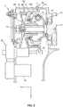
- Fig. 1 is a partial cross-sectional view showing a configuration example of a displacement detection device and a continuously variable transmission device according to an embodiment.
- Fig. 2 is a partial cross-sectional view showing a configuration example of the displacement detection device and the continuously variable transmission device when a movable sheave has moved.
- the vertically downward direction in Figs. 1 and 2 is defined as a z-axis direction
- the horizontally leftward direction is defined as an x-axis direction
- the near side direction is defined as a y-axis direction.
- the continuously variable transmission device 10 is a V-belt type continuously variable transmission device for example and includes a pulley shaft 12 formed at one end of a crankshaft 11, a drive pulley 20 supported by the pulley shaft 12, a driven pulley (not shown), and a V-belt 22 wound around the drive pulley 20 and the driven pulley in a transmission case 28.
- the drive pulley 20 is composed of a fixed sheave 15 fixed to the pulley shaft 12 and a movable sheave 21 supported by the pulley shaft 12 and movable with respect to the fixed sheave 15 and the V-belt 22 is provided to be wound around between the both sheaves 15 and 21.
- a ramp plate 13 is fixed to the pulley shaft 12 behind the movable sheave 21, and a plurality of centrifugal weights 19 are held between the movable sheave 21 and the ramp plate 13.
- the centrifugal weights 19 move radially outward along a cam face 17 of the movable sheave 21, and the movable sheave 21 is moved toward the fixed sheave 15 side (see Fig. 2 ).
- the distance between the fixed sheave 15 and the movable sheave 21 reduces and the winding radius of the V-belt 22 increases.
- the sliding surface for the V-belt 22 and the cam face 17 of the movable sheave 21 are formed as separate components, and an arm 26 is connected to a boss 23 located between the both surfaces via a bearing 24. Further, an output rod of an actuator 30 for moving the movable sheave 21 in cooperation with the centrifugal weights 19 is connected to the tip of the arm 26.
- the actuator 30 connects a motor 32 as a drive source to the main body, and the main body includes inside, a reduction gear group for reducing the output of the motor 32 and a nut member rotationally driven by the motor 32 via the reduction gear group.
- the actuator 30 has the output rod 46 that protrudes from the main body by driving of the motor 32.
- a U-shaped groove to which the arm 26 is connected is provided at a tip of the output rod 46. Further, the output rod 46 is supported by a bearing disposed on the main body of the actuator 30.
- the arm 26 When the output rod 46 moves, the arm 26 also moves integrally with the output rod 46 and moves the movable sheave 21 with respect to the fixed sheave 15. As a result, the distance between the fixed sheave 15 and the movable sheave 21, that is, the winding radius of the V-belt 22 changes.
- Fig. 1 when the output rod 46 moves to the right, the distance between the fixed sheave 15 and the movable sheave 21 increases, and the winding radius of the V-belt 22 reduces.
- Fig. 2 when the output rod 46 moves to the left, the distance between the fixed sheave 15 and the movable sheave 21 reduces, and the winding radius of the V-belt 22 increases.
- the displacement amount of the movable sheave 21 is assumed to be about several tens of millimeters (15 mm for example).
- the motor 32 is controlled by a control unit (not shown) .
- the control by the control unit is performed based on the displacement amount of the movable sheave 21 detected by a sensor 60. That is, the movement of the movable sheave 21 is controlled by using the displacement amount of the movable sheave 21 as feedback information.
- the sensor 60 is inserted into a hole provided on the transmission case 28 and detects the position of a concave portion 210 provided on a circumferential surface 211 of the movable sheave 21 over the whole circumference.
- the concave portion 210 and the sensor 60 are provided so that the left end of the concave portion 210 substantially coincides with the detecting position of the sensor 60 in a state where the distance between the fixed sheave 15 and the movable sheave 21 is large as shown in Fig. 1 , and so that the right end of the concave portion 210 substantially coincides with the detecting position of the sensor 60 in a state where the distance between the fixed sheave 15 and the movable sheave 21 is small as shown in Fig. 2 .
- the movable sheave 21 is formed of a general magnetic material, for example, a material such as iron. It should be noted that the sensor 60 may be installed without the hole when the transmission case 28 is made of a non-magnetic material such as stainless steel, aluminum, brass.
- Fig. 3 is a partial cross-sectional view showing a configuration of the sensor 60.
- the sensor 60 is formed by molding a Hall IC 61 and a magnet 62 into a cylindrical shape using a synthetic resin or the like for example.
- the Hall IC 61 is disposed in the magnetic field of the magnet 62 and detects the x component and the z component of the magnetic field which changes in accordance with the displacement of the concave portion 210 (see Figs. 1 and 2 ).
- the magnet 62 is a permanent magnet formed using a material such as ferrite, samarium cobalt, neodymium, and the magnetization direction Dm is the z direction.
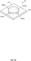
- Figs. 4A and 4B are a perspective view and a cross-sectional view showing the configuration of the Hall IC.
- the Hall IC 61 detects magnetic flux density in the x, y and z directions by having, for example, a flat plate-shaped substrate 610 having a thickness in the z direction; Hall elements 610x 1 , 610x 2 , 610y 1 and 610y 2 which are provided on the substrate 610, each of which has a detection surface parallel to the xy plane, and whose detecting direction D sz is the z direction as magnetic detection elements; a magnetic concentrator 611 that is provided so as to partially overlap the Hall elements 610x 1 , 610x 2 , 610y 1 and 610y 2 , and that converts the magnetic flux in the x direction or the y direction into that in the z direction, and then that allows the Hall elements 610x 1 , 610x 2 , 610y 1 and 610y 2 to detect the magnetic flux; and a signal processing circuit (not shown) for processing signals output from the Hall elements 610x 1 , 610
- the Hall IC 61 can obtain output proportional to the magnetic flux density in the x direction and the y direction by acquiring the difference between the output values of the Hall elements 610x 1 and 610x 2 and the difference between the output values of the Hall elements 610y 1 and 610y 2 by using a triaxial position sensor manufactured by Melexis or the like for example. The relationship between the magnetic flux density and the output will be described later.
- the distance between the Hall elements 610x 1 and 610x 2 and the distance between the Hall elements 610y 1 and 610y 2 are 0.2 mm, the thickness of the package mold part in the z direction is 1.5 mm, the width in the x direction is 4.1 mm, and the height in the y direction is 3 mm.
- Permalloy can be used as the magnetic concentrator 611 of the sensor 60. Further, in the sensor 60, the Hall elements 610y 1 and 610y 2 may be omitted.
- the detecting directions are the x, y and z directions
- another type of element such as an MR element may be used instead of the Hall IC 61, and when the detecting directions include the x, y and z directions, a multi-axis magnetic detection IC in which a magnetic detection element is arranged in each of the plurality of axial directions may be used.
- Figs. 5A to 5C are schematic diagrams for illustrating the operation of the displacement detection device.
- the magnetic flux density detected by the Hall IC 61 is graphically shown in Figs. 6 and 7 below.
- Fig. 6 is a graph showing the x component of the magnetic field detected by the Hall IC 61 with respect to the displacement amount of the movable sheave 21.
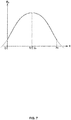
- Fig. 7 is a graph showing the z component of the magnetic field detected by the Hall IC 61 with respect to the displacement amount of the movable sheave 21.
- Fig. 8 is a graph showing the output of the sensor 60 with respect to the displacement amount of the movable sheave 21.
- the sensor 60 calculates arctan (B z /B x ) from the x component B x and the z component B z of the abovementioned magnetic flux density, calculates an angle ⁇ formed by the direction of the magnetic flux and the x axis, and outputs a voltage V out proportional to the angle ⁇ .
- the concave portion 210 is formed on the circumferential surface 211 of the movable sheave 21 that is the measuring object, and the magnetic flux induced to the concave portion 210 from the magnet 62 is detected by the sensor 60, and thus, the position of the movable sheave 21 is directly detected without contact.
- the Hall IC 61 detects the magnetic flux density in the x direction and the z direction, but may detect the position of the movable sheave 21 from the magnetic flux density detected only in the x direction or only in the z direction.
- a Hall IC can be used in which two Hall elements are arranged in the x direction at the center of the substrate and two magnetic concentrators are arranged outside the Hall elements.
- Fig. 9 is a cross-sectional view showing a modification example of the configuration of the movable sheave.
- a movable sheave 21a having a protrusion 212 on the circumferential surface 211 may be used.
- the protrusion 212 may have a dome shape which is a shape of an inverted concave portion 210, in addition to a shape whose end portion forms a right angle in the cross section as shown in Fig. 9 . Further, the protrusion 212 may be configured as a separate component from the movable sheave 21a. In addition, in the case of forming the concave portion, the periphery of the concave portion may be formed as a separate component.
- Fig. 10 is a cross-sectional view showing a modification example of the configuration of the Hall IC.
- a Hall IC 61b in which the Hall element 610x 3 is disposed perpendicularly to the substrate surface of a substrate 610b may be used as the Hall IC to be used for the sensor 60 so that the detecting direction D sx is arranged in the x direction.
- Fig. 11 is a cross-sectional view showing a modification example of the configuration of the displacement detection device.
- a sensor 60a may be used in which a Hall IC 61a whose detecting direction D sx is the normal direction of the substrate surface is used and the normal direction of the substrate surface of the Hall IC 61a is arranged in the x direction so that the detecting direction D sx coincides with the x direction.
- the sensitivity of magnetic detection can be improved by disposing the bottom surface of the sensor 60a closer to the axis of the movable sheave 21 than the circumferential surface 211.
- the displacement detection device is used for a continuously variable transmission device.
- the displacement detection device can be similarly used for any measuring object having a circumferential surface.
- the other devices include a motor shaft and the like.
- displacement can be detected without contact.
- the measuring object may not necessarily be rotated. In this case, it is not necessary to provide the concave portion or the protrusion over the entire circumference.
- the combination of the sensor and the magnet of the above-described embodiment is an example, and these may be used by being appropriately selected and changed to new combinations as long as the function of positional detection is not impaired and the gist of the present invention is not changed.
- a displacement detection device and a continuously variable transmission device for directly detecting the position of a movable sheave are provided.
Landscapes
- Physics & Mathematics (AREA)
- General Physics & Mathematics (AREA)
- Engineering & Computer Science (AREA)
- General Engineering & Computer Science (AREA)
- Mechanical Engineering (AREA)
- Transmission And Conversion Of Sensor Element Output (AREA)
- Transmissions By Endless Flexible Members (AREA)
- Measurement Of Length, Angles, Or The Like Using Electric Or Magnetic Means (AREA)
Applications Claiming Priority (2)
| Application Number | Priority Date | Filing Date | Title |
|---|---|---|---|
| JP2015189669A JP2017067480A (ja) | 2015-09-28 | 2015-09-28 | 変位検出装置及び無段変速装置 |
| PCT/JP2016/075919 WO2017056854A1 (ja) | 2015-09-28 | 2016-09-05 | 変位検出装置及び無段変速装置 |
Publications (3)
| Publication Number | Publication Date |
|---|---|
| EP3358291A1 true EP3358291A1 (de) | 2018-08-08 |
| EP3358291A4 EP3358291A4 (de) | 2019-06-26 |
| EP3358291B1 EP3358291B1 (de) | 2021-07-14 |
Family
ID=58423339
Family Applications (1)
| Application Number | Title | Priority Date | Filing Date |
|---|---|---|---|
| EP16851030.3A Active EP3358291B1 (de) | 2015-09-28 | 2016-09-05 | Stufenloses getriebe |
Country Status (5)
| Country | Link |
|---|---|
| US (2) | US10612942B2 (de) |
| EP (1) | EP3358291B1 (de) |
| JP (1) | JP2017067480A (de) |
| CN (1) | CN108351194B (de) |
| WO (1) | WO2017056854A1 (de) |
Families Citing this family (5)
| Publication number | Priority date | Publication date | Assignee | Title |
|---|---|---|---|---|
| JP6550098B2 (ja) | 2017-06-26 | 2019-07-24 | メレキシス テクノロジーズ エス エー | 回転角検出装置、姿勢制御装置、自動操舵装置及びスロットル装置 |
| JP6550099B2 (ja) | 2017-06-26 | 2019-07-24 | メレキシス テクノロジーズ エス エー | 回転角検出装置、姿勢制御装置、自動操舵装置及びスロットル装置 |
| DE102019124371B9 (de) * | 2019-09-11 | 2021-04-29 | Infineon Technologies Ag | Vorrichtung und verfahren zum ermitteln eines drehwinkels |
| CN112857169A (zh) * | 2021-02-08 | 2021-05-28 | 盖茨优霓塔传动系统(苏州)有限公司 | 无级变速带测量工具 |
| JP2025158491A (ja) * | 2024-04-04 | 2025-10-17 | ヤマハ発動機株式会社 | 無段変速機、及び、無段変速機を有する鞍乗型車両 |
Family Cites Families (20)
| Publication number | Priority date | Publication date | Assignee | Title |
|---|---|---|---|---|
| US5315244A (en) * | 1989-11-17 | 1994-05-24 | Visi-Trak Corporation | Magnetic sensor with laminated field concentrating flux bar |
| DE19623742A1 (de) * | 1996-06-14 | 1997-12-18 | Wittenstein Motion Contr Gmbh | Einrichtung zur Verschiebeweg- und/oder Positionserfassung bei einem Spindeltrieb |
| DE102004060771B4 (de) * | 2004-12-17 | 2006-12-21 | Audi Ag | Vorrichtung zum Schalten von Übersetzungsänderungen |
| JP4877905B2 (ja) * | 2005-08-03 | 2012-02-15 | 日産自動車株式会社 | 自動マニュアルトランスミッションのシフト位置検出装置 |
| US7242180B1 (en) * | 2006-05-10 | 2007-07-10 | Key Safety Systems, Inc. | Rotationally orientated dual differential hall effect speed and direction gear tooth sensor assembly |
| JP4842741B2 (ja) * | 2006-09-01 | 2011-12-21 | ヤマハ発動機株式会社 | 鞍乗型車両 |
| DE102006045827A1 (de) * | 2006-09-22 | 2008-04-10 | Dichtungstechnik G. Bruss Gmbh & Co. Kg | Axialverschiebbares Bauteil insbesondere in einem Kraftfahrzeugmotor oder -getriebe |
| JP2009204331A (ja) * | 2008-02-26 | 2009-09-10 | Seiko Instruments Inc | 位置検出磁気センサ |
| JP2010223252A (ja) * | 2009-03-19 | 2010-10-07 | Honda Motor Co Ltd | 位置検出装置及びそれを備えたベルト式無段変速機 |
| JP2010249263A (ja) | 2009-04-17 | 2010-11-04 | Toyota Motor Corp | ベルト式無段変速機 |
| JP5313178B2 (ja) * | 2010-01-05 | 2013-10-09 | 日立オートモティブシステムズ株式会社 | 位置センサ |
| US9593967B2 (en) * | 2011-07-17 | 2017-03-14 | Bourns, Inc. | High-resolution non-contacting multi-turn sensing systems and methods |
| DE102011115302A1 (de) * | 2011-09-29 | 2013-04-04 | Tyco Electronics Amp Gmbh | Verfahren zum berührungslosen Messen einer relativen Position mittels eines Hallsensors |
| JP5472764B2 (ja) * | 2012-04-11 | 2014-04-16 | 株式会社デンソー | ストローク量検出装置 |
| DE102012211383A1 (de) * | 2012-06-29 | 2014-01-02 | Continental Automotive Gmbh | Magnetfelderzeuger und Sensorvorrichtung für den Einsatz beim Ermitteln eines Rotationswinkels |
| JP5818104B2 (ja) * | 2012-10-12 | 2015-11-18 | 株式会社デンソー | 回転角度検出装置 |
| JP2014196780A (ja) | 2013-03-29 | 2014-10-16 | 武蔵精密工業株式会社 | Vベルト式無段変速機 |
| US9267781B2 (en) * | 2013-11-19 | 2016-02-23 | Infineon Technologies Ag | On-axis magnetic field angle sensors, systems and methods |
| KR102185620B1 (ko) * | 2013-12-23 | 2020-12-02 | 알레그로 마이크로시스템스, 엘엘씨 | 자기장 센서 및 운동 라인을 따른 자기장 센서와 타겟 물체의 상대적 위치를 감지하는 방법 |
| US10704950B2 (en) * | 2017-06-05 | 2020-07-07 | Yazaki Corporation | Liquid level detecting device |
-
2015
- 2015-09-28 JP JP2015189669A patent/JP2017067480A/ja active Pending
-
2016
- 2016-09-05 US US15/757,257 patent/US10612942B2/en active Active
- 2016-09-05 WO PCT/JP2016/075919 patent/WO2017056854A1/ja not_active Ceased
- 2016-09-05 EP EP16851030.3A patent/EP3358291B1/de active Active
- 2016-09-05 CN CN201680059224.7A patent/CN108351194B/zh active Active
-
2020
- 2020-03-27 US US16/833,444 patent/US11150109B2/en active Active
Also Published As
| Publication number | Publication date |
|---|---|
| WO2017056854A1 (ja) | 2017-04-06 |
| EP3358291B1 (de) | 2021-07-14 |
| EP3358291A4 (de) | 2019-06-26 |
| JP2017067480A (ja) | 2017-04-06 |
| US20180274944A1 (en) | 2018-09-27 |
| US20200225061A1 (en) | 2020-07-16 |
| CN108351194A (zh) | 2018-07-31 |
| US10612942B2 (en) | 2020-04-07 |
| CN108351194B (zh) | 2020-12-18 |
| US11150109B2 (en) | 2021-10-19 |
Similar Documents
| Publication | Publication Date | Title |
|---|---|---|
| US11150109B2 (en) | Displacement detecting device and continuously variable transmission device | |
| EP2454558B1 (de) | Hall-effekt-sensoranordnung | |
| US9080895B2 (en) | Magnetic position sensor assembly for measurement of rotational angular position of a rotating structure | |
| EP3273095B1 (de) | Verschiebungserkennungsvorrichtung | |
| US11821763B2 (en) | System, method and object for high accuracy magnetic position sensing | |
| CN111801551A (zh) | 编码器装置及其制造方法、驱动装置、工作台装置及机械手装置 | |
| US20160146679A1 (en) | Arrangements and method for measuring a force or a torque on a machine element | |
| EP2103909A1 (de) | Drehwinkel-detektionseinrichtung | |
| CN102713524A (zh) | 用于确定目标的位置和方向的磁传感器 | |
| JP6559629B2 (ja) | 外部浮遊磁場を補償する装置または磁場勾配が磁場センサに及ぼす影響を補償する装置 | |
| US11561117B2 (en) | Absolute encoder for detecting rotation angle | |
| JP2016156682A (ja) | 回転検出装置 | |
| CN111721327A (zh) | 磁场发生组件、位置检测装置及磁场发生组件的制造方法 | |
| EP3252426A1 (de) | Verlagerungsdetektionsvorrichtung | |
| US20240159570A1 (en) | Magnet sensor and ferromagnetic poles | |
| JP2021143833A (ja) | 磁気検出装置 | |
| JP5444085B2 (ja) | インデックスセンサ | |
| EP2860495A1 (de) | Winkelsensor | |
| EP3062068A1 (de) | Berührungsfreie Sensorik |
Legal Events
| Date | Code | Title | Description |
|---|---|---|---|
| STAA | Information on the status of an ep patent application or granted ep patent |
Free format text: STATUS: THE INTERNATIONAL PUBLICATION HAS BEEN MADE |
|
| PUAI | Public reference made under article 153(3) epc to a published international application that has entered the european phase |
Free format text: ORIGINAL CODE: 0009012 |
|
| STAA | Information on the status of an ep patent application or granted ep patent |
Free format text: STATUS: REQUEST FOR EXAMINATION WAS MADE |
|
| 17P | Request for examination filed |
Effective date: 20180405 |
|
| AK | Designated contracting states |
Kind code of ref document: A1 Designated state(s): AL AT BE BG CH CY CZ DE DK EE ES FI FR GB GR HR HU IE IS IT LI LT LU LV MC MK MT NL NO PL PT RO RS SE SI SK SM TR |
|
| AX | Request for extension of the european patent |
Extension state: BA ME |
|
| RAP1 | Party data changed (applicant data changed or rights of an application transferred) |
Owner name: MELEXIS TECHNOLOGIES SA |
|
| DAV | Request for validation of the european patent (deleted) | ||
| DAX | Request for extension of the european patent (deleted) | ||
| A4 | Supplementary search report drawn up and despatched |
Effective date: 20190528 |
|
| RIC1 | Information provided on ipc code assigned before grant |
Ipc: G01D 5/14 20060101ALI20190522BHEP Ipc: G01B 7/14 20060101ALI20190522BHEP Ipc: F16H 61/662 20060101AFI20190522BHEP Ipc: G01D 5/12 20060101ALI20190522BHEP |
|
| REG | Reference to a national code |
Ref country code: DE Ref legal event code: R079 Ref document number: 602016060733 Country of ref document: DE Free format text: PREVIOUS MAIN CLASS: G01B0007000000 Ipc: G01B0007140000 |
|
| GRAP | Despatch of communication of intention to grant a patent |
Free format text: ORIGINAL CODE: EPIDOSNIGR1 |
|
| STAA | Information on the status of an ep patent application or granted ep patent |
Free format text: STATUS: GRANT OF PATENT IS INTENDED |
|
| RIC1 | Information provided on ipc code assigned before grant |
Ipc: G01D 5/14 20060101ALI20210204BHEP Ipc: F16H 9/08 20060101ALI20210204BHEP Ipc: G01B 7/14 20060101AFI20210204BHEP |
|
| INTG | Intention to grant announced |
Effective date: 20210222 |
|
| GRAS | Grant fee paid |
Free format text: ORIGINAL CODE: EPIDOSNIGR3 |
|
| GRAA | (expected) grant |
Free format text: ORIGINAL CODE: 0009210 |
|
| STAA | Information on the status of an ep patent application or granted ep patent |
Free format text: STATUS: THE PATENT HAS BEEN GRANTED |
|
| AK | Designated contracting states |
Kind code of ref document: B1 Designated state(s): AL AT BE BG CH CY CZ DE DK EE ES FI FR GB GR HR HU IE IS IT LI LT LU LV MC MK MT NL NO PL PT RO RS SE SI SK SM TR |
|
| REG | Reference to a national code |
Ref country code: GB Ref legal event code: FG4D |
|
| REG | Reference to a national code |
Ref country code: IE Ref legal event code: FG4D |
|
| REG | Reference to a national code |
Ref country code: DE Ref legal event code: R096 Ref document number: 602016060733 Country of ref document: DE |
|
| REG | Reference to a national code |
Ref country code: AT Ref legal event code: REF Ref document number: 1410995 Country of ref document: AT Kind code of ref document: T Effective date: 20210815 |
|
| REG | Reference to a national code |
Ref country code: LT Ref legal event code: MG9D |
|
| REG | Reference to a national code |
Ref country code: NL Ref legal event code: MP Effective date: 20210714 |
|
| REG | Reference to a national code |
Ref country code: AT Ref legal event code: MK05 Ref document number: 1410995 Country of ref document: AT Kind code of ref document: T Effective date: 20210714 |
|
| PG25 | Lapsed in a contracting state [announced via postgrant information from national office to epo] |
Ref country code: HR Free format text: LAPSE BECAUSE OF FAILURE TO SUBMIT A TRANSLATION OF THE DESCRIPTION OR TO PAY THE FEE WITHIN THE PRESCRIBED TIME-LIMIT Effective date: 20210714 Ref country code: FI Free format text: LAPSE BECAUSE OF FAILURE TO SUBMIT A TRANSLATION OF THE DESCRIPTION OR TO PAY THE FEE WITHIN THE PRESCRIBED TIME-LIMIT Effective date: 20210714 Ref country code: ES Free format text: LAPSE BECAUSE OF FAILURE TO SUBMIT A TRANSLATION OF THE DESCRIPTION OR TO PAY THE FEE WITHIN THE PRESCRIBED TIME-LIMIT Effective date: 20210714 Ref country code: PT Free format text: LAPSE BECAUSE OF FAILURE TO SUBMIT A TRANSLATION OF THE DESCRIPTION OR TO PAY THE FEE WITHIN THE PRESCRIBED TIME-LIMIT Effective date: 20211115 Ref country code: NL Free format text: LAPSE BECAUSE OF FAILURE TO SUBMIT A TRANSLATION OF THE DESCRIPTION OR TO PAY THE FEE WITHIN THE PRESCRIBED TIME-LIMIT Effective date: 20210714 Ref country code: NO Free format text: LAPSE BECAUSE OF FAILURE TO SUBMIT A TRANSLATION OF THE DESCRIPTION OR TO PAY THE FEE WITHIN THE PRESCRIBED TIME-LIMIT Effective date: 20211014 Ref country code: LT Free format text: LAPSE BECAUSE OF FAILURE TO SUBMIT A TRANSLATION OF THE DESCRIPTION OR TO PAY THE FEE WITHIN THE PRESCRIBED TIME-LIMIT Effective date: 20210714 Ref country code: BG Free format text: LAPSE BECAUSE OF FAILURE TO SUBMIT A TRANSLATION OF THE DESCRIPTION OR TO PAY THE FEE WITHIN THE PRESCRIBED TIME-LIMIT Effective date: 20211014 Ref country code: AT Free format text: LAPSE BECAUSE OF FAILURE TO SUBMIT A TRANSLATION OF THE DESCRIPTION OR TO PAY THE FEE WITHIN THE PRESCRIBED TIME-LIMIT Effective date: 20210714 Ref country code: RS Free format text: LAPSE BECAUSE OF FAILURE TO SUBMIT A TRANSLATION OF THE DESCRIPTION OR TO PAY THE FEE WITHIN THE PRESCRIBED TIME-LIMIT Effective date: 20210714 Ref country code: SE Free format text: LAPSE BECAUSE OF FAILURE TO SUBMIT A TRANSLATION OF THE DESCRIPTION OR TO PAY THE FEE WITHIN THE PRESCRIBED TIME-LIMIT Effective date: 20210714 |
|
| PG25 | Lapsed in a contracting state [announced via postgrant information from national office to epo] |
Ref country code: PL Free format text: LAPSE BECAUSE OF FAILURE TO SUBMIT A TRANSLATION OF THE DESCRIPTION OR TO PAY THE FEE WITHIN THE PRESCRIBED TIME-LIMIT Effective date: 20210714 Ref country code: LV Free format text: LAPSE BECAUSE OF FAILURE TO SUBMIT A TRANSLATION OF THE DESCRIPTION OR TO PAY THE FEE WITHIN THE PRESCRIBED TIME-LIMIT Effective date: 20210714 Ref country code: GR Free format text: LAPSE BECAUSE OF FAILURE TO SUBMIT A TRANSLATION OF THE DESCRIPTION OR TO PAY THE FEE WITHIN THE PRESCRIBED TIME-LIMIT Effective date: 20211015 |
|
| REG | Reference to a national code |
Ref country code: DE Ref legal event code: R097 Ref document number: 602016060733 Country of ref document: DE |
|
| PG25 | Lapsed in a contracting state [announced via postgrant information from national office to epo] |
Ref country code: DK Free format text: LAPSE BECAUSE OF FAILURE TO SUBMIT A TRANSLATION OF THE DESCRIPTION OR TO PAY THE FEE WITHIN THE PRESCRIBED TIME-LIMIT Effective date: 20210714 |
|
| REG | Reference to a national code |
Ref country code: CH Ref legal event code: PL |
|
| PLBE | No opposition filed within time limit |
Free format text: ORIGINAL CODE: 0009261 |
|
| REG | Reference to a national code |
Ref country code: BE Ref legal event code: MM Effective date: 20210930 |
|
| STAA | Information on the status of an ep patent application or granted ep patent |
Free format text: STATUS: NO OPPOSITION FILED WITHIN TIME LIMIT |
|
| PG25 | Lapsed in a contracting state [announced via postgrant information from national office to epo] |
Ref country code: SM Free format text: LAPSE BECAUSE OF FAILURE TO SUBMIT A TRANSLATION OF THE DESCRIPTION OR TO PAY THE FEE WITHIN THE PRESCRIBED TIME-LIMIT Effective date: 20210714 Ref country code: SK Free format text: LAPSE BECAUSE OF FAILURE TO SUBMIT A TRANSLATION OF THE DESCRIPTION OR TO PAY THE FEE WITHIN THE PRESCRIBED TIME-LIMIT Effective date: 20210714 Ref country code: RO Free format text: LAPSE BECAUSE OF FAILURE TO SUBMIT A TRANSLATION OF THE DESCRIPTION OR TO PAY THE FEE WITHIN THE PRESCRIBED TIME-LIMIT Effective date: 20210714 Ref country code: MC Free format text: LAPSE BECAUSE OF FAILURE TO SUBMIT A TRANSLATION OF THE DESCRIPTION OR TO PAY THE FEE WITHIN THE PRESCRIBED TIME-LIMIT Effective date: 20210714 Ref country code: EE Free format text: LAPSE BECAUSE OF FAILURE TO SUBMIT A TRANSLATION OF THE DESCRIPTION OR TO PAY THE FEE WITHIN THE PRESCRIBED TIME-LIMIT Effective date: 20210714 Ref country code: CZ Free format text: LAPSE BECAUSE OF FAILURE TO SUBMIT A TRANSLATION OF THE DESCRIPTION OR TO PAY THE FEE WITHIN THE PRESCRIBED TIME-LIMIT Effective date: 20210714 Ref country code: AL Free format text: LAPSE BECAUSE OF FAILURE TO SUBMIT A TRANSLATION OF THE DESCRIPTION OR TO PAY THE FEE WITHIN THE PRESCRIBED TIME-LIMIT Effective date: 20210714 |
|
| 26N | No opposition filed |
Effective date: 20220419 |
|
| GBPC | Gb: european patent ceased through non-payment of renewal fee |
Effective date: 20211014 |
|
| PG25 | Lapsed in a contracting state [announced via postgrant information from national office to epo] |
Ref country code: LU Free format text: LAPSE BECAUSE OF NON-PAYMENT OF DUE FEES Effective date: 20210905 Ref country code: IT Free format text: LAPSE BECAUSE OF FAILURE TO SUBMIT A TRANSLATION OF THE DESCRIPTION OR TO PAY THE FEE WITHIN THE PRESCRIBED TIME-LIMIT Effective date: 20210714 Ref country code: IE Free format text: LAPSE BECAUSE OF NON-PAYMENT OF DUE FEES Effective date: 20210905 Ref country code: GB Free format text: LAPSE BECAUSE OF NON-PAYMENT OF DUE FEES Effective date: 20211014 Ref country code: BE Free format text: LAPSE BECAUSE OF NON-PAYMENT OF DUE FEES Effective date: 20210930 |
|
| PG25 | Lapsed in a contracting state [announced via postgrant information from national office to epo] |
Ref country code: LI Free format text: LAPSE BECAUSE OF NON-PAYMENT OF DUE FEES Effective date: 20210930 Ref country code: CH Free format text: LAPSE BECAUSE OF NON-PAYMENT OF DUE FEES Effective date: 20210930 |
|
| P01 | Opt-out of the competence of the unified patent court (upc) registered |
Effective date: 20230517 |
|
| PG25 | Lapsed in a contracting state [announced via postgrant information from national office to epo] |
Ref country code: CY Free format text: LAPSE BECAUSE OF FAILURE TO SUBMIT A TRANSLATION OF THE DESCRIPTION OR TO PAY THE FEE WITHIN THE PRESCRIBED TIME-LIMIT Effective date: 20210714 |
|
| PG25 | Lapsed in a contracting state [announced via postgrant information from national office to epo] |
Ref country code: HU Free format text: LAPSE BECAUSE OF FAILURE TO SUBMIT A TRANSLATION OF THE DESCRIPTION OR TO PAY THE FEE WITHIN THE PRESCRIBED TIME-LIMIT; INVALID AB INITIO Effective date: 20160905 |
|
| PG25 | Lapsed in a contracting state [announced via postgrant information from national office to epo] |
Ref country code: MK Free format text: LAPSE BECAUSE OF FAILURE TO SUBMIT A TRANSLATION OF THE DESCRIPTION OR TO PAY THE FEE WITHIN THE PRESCRIBED TIME-LIMIT Effective date: 20210714 |
|
| PG25 | Lapsed in a contracting state [announced via postgrant information from national office to epo] |
Ref country code: MT Free format text: LAPSE BECAUSE OF FAILURE TO SUBMIT A TRANSLATION OF THE DESCRIPTION OR TO PAY THE FEE WITHIN THE PRESCRIBED TIME-LIMIT Effective date: 20210714 |
|
| PGFP | Annual fee paid to national office [announced via postgrant information from national office to epo] |
Ref country code: DE Payment date: 20250820 Year of fee payment: 10 |
|
| PGFP | Annual fee paid to national office [announced via postgrant information from national office to epo] |
Ref country code: FR Payment date: 20250820 Year of fee payment: 10 |
|
| PG25 | Lapsed in a contracting state [announced via postgrant information from national office to epo] |
Ref country code: TR Free format text: LAPSE BECAUSE OF FAILURE TO SUBMIT A TRANSLATION OF THE DESCRIPTION OR TO PAY THE FEE WITHIN THE PRESCRIBED TIME-LIMIT Effective date: 20210714 |