EP3358263B1 - Device and method for regulating heating systems - Google Patents
Device and method for regulating heating systems Download PDFInfo
- Publication number
- EP3358263B1 EP3358263B1 EP18152988.4A EP18152988A EP3358263B1 EP 3358263 B1 EP3358263 B1 EP 3358263B1 EP 18152988 A EP18152988 A EP 18152988A EP 3358263 B1 EP3358263 B1 EP 3358263B1
- Authority
- EP
- European Patent Office
- Prior art keywords
- fluid
- inlet
- temperature
- outlet
- flow rate
- Prior art date
- Legal status (The legal status is an assumption and is not a legal conclusion. Google has not performed a legal analysis and makes no representation as to the accuracy of the status listed.)
- Active
Links
- 238000010438 heat treatment Methods 0.000 title claims description 98
- 230000001105 regulatory effect Effects 0.000 title claims description 81
- 238000000034 method Methods 0.000 title claims description 18
- 239000012530 fluid Substances 0.000 claims description 167
- 230000007423 decrease Effects 0.000 claims description 14
- 238000009434 installation Methods 0.000 claims description 9
- 238000011144 upstream manufacturing Methods 0.000 claims description 8
- 238000012546 transfer Methods 0.000 claims description 7
- 230000003247 decreasing effect Effects 0.000 claims description 6
- 238000004891 communication Methods 0.000 claims description 3
- XLYOFNOQVPJJNP-UHFFFAOYSA-N water Substances O XLYOFNOQVPJJNP-UHFFFAOYSA-N 0.000 description 73
- 238000009408 flooring Methods 0.000 description 8
- 230000000694 effects Effects 0.000 description 6
- 238000013021 overheating Methods 0.000 description 3
- 230000033228 biological regulation Effects 0.000 description 2
- 238000005266 casting Methods 0.000 description 2
- 230000006866 deterioration Effects 0.000 description 2
- 238000012423 maintenance Methods 0.000 description 2
- 238000007726 management method Methods 0.000 description 2
- 239000000463 material Substances 0.000 description 2
- 238000009428 plumbing Methods 0.000 description 2
- 238000007789 sealing Methods 0.000 description 2
- 229910001369 Brass Inorganic materials 0.000 description 1
- 230000000903 blocking effect Effects 0.000 description 1
- 239000010951 brass Substances 0.000 description 1
- 230000002860 competitive effect Effects 0.000 description 1
- 230000008602 contraction Effects 0.000 description 1
- 230000001276 controlling effect Effects 0.000 description 1
- 238000001816 cooling Methods 0.000 description 1
- 230000001419 dependent effect Effects 0.000 description 1
- 238000013461 design Methods 0.000 description 1
- 238000007599 discharging Methods 0.000 description 1
- 238000009826 distribution Methods 0.000 description 1
- 238000004519 manufacturing process Methods 0.000 description 1
- 239000007769 metal material Substances 0.000 description 1
- 238000012986 modification Methods 0.000 description 1
- 230000004048 modification Effects 0.000 description 1
- 238000011017 operating method Methods 0.000 description 1
- 238000009418 renovation Methods 0.000 description 1
- 230000000284 resting effect Effects 0.000 description 1
- 238000000638 solvent extraction Methods 0.000 description 1
Images


Classifications
-
- F—MECHANICAL ENGINEERING; LIGHTING; HEATING; WEAPONS; BLASTING
- F24—HEATING; RANGES; VENTILATING
- F24D—DOMESTIC- OR SPACE-HEATING SYSTEMS, e.g. CENTRAL HEATING SYSTEMS; DOMESTIC HOT-WATER SUPPLY SYSTEMS; ELEMENTS OR COMPONENTS THEREFOR
- F24D15/00—Other domestic- or space-heating systems
-
- G—PHYSICS
- G05—CONTROLLING; REGULATING
- G05D—SYSTEMS FOR CONTROLLING OR REGULATING NON-ELECTRIC VARIABLES
- G05D23/00—Control of temperature
- G05D23/01—Control of temperature without auxiliary power
- G05D23/02—Control of temperature without auxiliary power with sensing element expanding and contracting in response to changes of temperature
- G05D23/021—Control of temperature without auxiliary power with sensing element expanding and contracting in response to changes of temperature the sensing element being a non-metallic solid, e.g. elastomer, paste
- G05D23/022—Control of temperature without auxiliary power with sensing element expanding and contracting in response to changes of temperature the sensing element being a non-metallic solid, e.g. elastomer, paste the sensing element being placed within a regulating fluid flow
-
- F—MECHANICAL ENGINEERING; LIGHTING; HEATING; WEAPONS; BLASTING
- F24—HEATING; RANGES; VENTILATING
- F24D—DOMESTIC- OR SPACE-HEATING SYSTEMS, e.g. CENTRAL HEATING SYSTEMS; DOMESTIC HOT-WATER SUPPLY SYSTEMS; ELEMENTS OR COMPONENTS THEREFOR
- F24D19/00—Details
-
- F—MECHANICAL ENGINEERING; LIGHTING; HEATING; WEAPONS; BLASTING
- F24—HEATING; RANGES; VENTILATING
- F24D—DOMESTIC- OR SPACE-HEATING SYSTEMS, e.g. CENTRAL HEATING SYSTEMS; DOMESTIC HOT-WATER SUPPLY SYSTEMS; ELEMENTS OR COMPONENTS THEREFOR
- F24D19/00—Details
- F24D19/10—Arrangement or mounting of control or safety devices
- F24D19/1006—Arrangement or mounting of control or safety devices for water heating systems
- F24D19/1009—Arrangement or mounting of control or safety devices for water heating systems for central heating
- F24D19/1015—Arrangement or mounting of control or safety devices for water heating systems for central heating using a valve or valves
- F24D19/1018—Radiator valves
-
- F—MECHANICAL ENGINEERING; LIGHTING; HEATING; WEAPONS; BLASTING
- F24—HEATING; RANGES; VENTILATING
- F24D—DOMESTIC- OR SPACE-HEATING SYSTEMS, e.g. CENTRAL HEATING SYSTEMS; DOMESTIC HOT-WATER SUPPLY SYSTEMS; ELEMENTS OR COMPONENTS THEREFOR
- F24D19/00—Details
- F24D19/10—Arrangement or mounting of control or safety devices
- F24D19/1006—Arrangement or mounting of control or safety devices for water heating systems
- F24D19/1009—Arrangement or mounting of control or safety devices for water heating systems for central heating
- F24D19/1015—Arrangement or mounting of control or safety devices for water heating systems for central heating using a valve or valves
- F24D19/1021—Arrangement or mounting of control or safety devices for water heating systems for central heating using a valve or valves a by pass valve
-
- G—PHYSICS
- G05—CONTROLLING; REGULATING
- G05D—SYSTEMS FOR CONTROLLING OR REGULATING NON-ELECTRIC VARIABLES
- G05D23/00—Control of temperature
-
- F—MECHANICAL ENGINEERING; LIGHTING; HEATING; WEAPONS; BLASTING
- F24—HEATING; RANGES; VENTILATING
- F24D—DOMESTIC- OR SPACE-HEATING SYSTEMS, e.g. CENTRAL HEATING SYSTEMS; DOMESTIC HOT-WATER SUPPLY SYSTEMS; ELEMENTS OR COMPONENTS THEREFOR
- F24D2220/00—Components of central heating installations excluding heat sources
- F24D2220/02—Fluid distribution means
- F24D2220/0257—Thermostatic valves
Definitions
- the object of the present invention is a regulating device for regulating heating systems, a heating system comprising this device, and a method for regulating heating systems.
- the invention refers to a regulating device for regulating the temperature and the flow of a fluid, generally hot water, in systems for heating spaces in buildings for residential or commercial use or for other uses.
- a fluid generally hot water
- the present invention thus falls within the technical field of heating systems.
- High temperature systems essentially comprise a boiler, a series of heating elements (including radiators, thermosiphons, heaters, convectors, etc.) arranged in the various rooms of a building and a plurality of collectors and pipes connecting the boiler and the radiator elements.
- low temperature systems comprise a plurality of radiant elements in the form of pipes, which are generally inserted under the flooring in the rooms, and at least one pair of collectors connecting the radiant elements to the boiler.
- the systems of the first type operate with water at a high temperature, typically on the order of about 60-80°C
- the systems of the second type must necessarily operate at lower temperatures, for example on the order of about 30-40°C, given that at higher temperatures there is a risk of deterioration of the flooring.
- mixed heating systems that comprise a high temperature circuit and a low temperature circuit, which are suitably connected with each other, and radiant elements of various types.
- the low temperature portions of a system must comprise suitable devices that are capable of managing and regulating the temperature of the fluid at different points of the system (that is, high temperature in the parts comprising radiators or thermosiphons and low temperature in the parts comprising radiant floor elements).
- such means can consist in a valve device, which is called a "limit temperature controller" in this field.
- This device consists in a thermostatic valve located on a line and provided with a temperature-sensitive element that commands the opening or the closing of the valve proportionally to the difference between the temperature of the fluid in the line and a reference temperature at which the valve has been set: the greater the difference in temperature, the greater the opening of the valve and therefore of the flow of water passing through it.
- the limit temperature controller typically comprises a knob for selecting the reference temperature.;when the temperature of the water in the line on which the controller is assembled reaches the reference temperature, the valve closes completely and there is no passage of water.
- the limit temperature controller is located at the outlet of the radiant floor line, before the return towards the boiler, whereas flow regulating elements are not positioned at the inlet of the radiant line, which is directly diverted from the high temperature circuit.
- the reference temperature of the controller is then set, for example at about 30°C.
- the high temperature water e.g. 60-70°C
- the limit temperature controller begins to receive a flow of hot water and gradually closes until it is totally closed, thus blocking the flow circulating in the floor line.
- an apparatus to control a flow of heated water from a boiler to a water outlet comprising a main housing defining an inlet, outlet and a flow path extending therebetween.
- the apparatus includes a first device, which restricts the heated water flow when the temperature of the water is below a first predetermined value.
- the first device comprises a bypass channel enabling permanent flow of heated water through the apparatus.
- the first device comprises a first thermostatic assembly having a temperature-sensitive expandable material that pushes a first rod against a retaining wall element so as to resist a force of a spring to open a variable opening.
- the Applicant has noted that this known solution is not without drawbacks and that it is improvable in several aspects.
- the operation of the limit temperature controller in theory makes it possible to find a point of fluid-dynamic equilibrium between water (which has released heat and has thus dropped in temperature) leaving the radiant line and new water (at high temperature) entering the radiant line.
- the limit temperature controller is connected to other components of the circuit, or included inside a heating plant, in which additional valves, collectors, pipes, pumps, etc. are present and which are needed for the operation of the entire heating system, which often also includes parts operating at high temperatures and parts operating at low temperatures.
- a heating plant is typically made up of a specific case that is located in a room, or applied to wall or built into a compartment afforded in a wall. The heating plant is also provided with a door that enables access thereto.
- the limit temperature controller thus operates in contact with or in proximity to elements of the system in which high temperature water flows, for example the pipes or the valves of the high temperature heating part and which can even reach temperatures of and over 80°C. Therefore, the temperature inside the entire heating plant tends to rise (for example up to and beyond 40°C) and the body of the limit temperature controller is also affected by this undesired heating effect. This constitutes a serious obstacle for proper operation of the radiant floor pipe. In fact, let us suppose that the limit temperature controller receives, from the end of the radiant line, water at a temperature equal to the reference temperature at which it has been set, and that it is therefore brought into the closed configuration.
- the radiant floor pipe cools (as it yields heat to the room) and the controller should perceive, water (incoming thereto) at a lower temperature.
- the water stopped at the inlet to the controller is heated by virtue of the overall heating of the heating plant (that is, of the entire case) and the sensitive element inside the controller continues to perceive a high temperature of the water, despite the fact that the floor line has cooled.
- heating inside the heating plant and the resulting undesired "lockout" of the limit temperature controller, despite the fact that the radiant line is cooling (and needs an amount of high temperature water to enter), are present regardless of the type or structure of the heating plant and irrespective of how the high temperature parts of the system are operating.
- the aim underlying the present invention in its various aspects and/or embodiments is to make available a device and a method for regulating heating systems which can be capable of overcoming one or more of the drawbacks cited hereinabove.
- a further aim of the present invention is to make available a regulating device for regulating heating systems which is capable of operating correctly inside heating plants or in proximity to components of a heating system operating at high temperatures.
- a further aim of the present invention is to make available a device and a method for regulating heating systems which make it possible to effectively connect a radiant floor pipe to a high temperature circuit, enabling proper management of the operating temperatures and of the flows inside the pipe.
- a further aim of the present invention is to make available a regulating device for regulating heating systems, said device being characterized by a high level of versatility and being capable of adapting to a great number and various types of different heating plants.
- a further aim of the present invention is to make available a regulating device for regulating heating systems, said device being characterized by a high level of operating reliability and/or by less susceptibility to damage and malfunctioning and/or being capable of offering simple and rapid maintenance and replacement.
- a further aim of the present invention is to make available a regulating device for regulating heating systems which is characterized by a simple and rational structure.
- a further aim of the present invention is to make available a regulating device for regulating heating systems which is characterized by limited production costs with respect to the performance and quality offered.
- a further aim of the present invention is to create alternative solutions with respect to the prior art for realizing regulating devices for regulating heating systems and/or to open new fields of design.
- a further aim of the present invention is to make available a regulating device that is capable of permitting new heating system designing.
- the invention concerns a regulating device for regulating heating systems, comprising:
- said plurality of operating configurations comprise (or ranges between) at least one maximum aperture configuration, in which there is a maximum flow rate of fluid passing from said inlet to said outlet, and a closed configuration, corresponding to a state in which said detected temperature of the fluid at the inlet is equal to or higher than said reference temperature.
- the valve element comprises members for the selection of said reference temperature, so that when the fluid incoming to said inlet reaches or exceeds this reference temperature, the valve element is brought into said closed configuration.
- said residual flow rate of fluid transferred from said inlet to said outlet in said closed configuration is comprised between 1 litre/hour and 10 litres/hour.
- said residual flow rate of fluid transferred from said inlet to said outlet in said closed configuration is comprised between 2 litres/hour and 8 litres/hour.
- said residual flow rate of fluid transferred from said inlet to said outlet in said closed configuration is comprised between 3 litres/hour and 6 litres/hour.
- said residual flow rate of fluid transferred from said inlet to said outlet in said closed configuration is comprised between 3.5 litres/hour and 5 litres/hour.
- said valve element comprises a thermostatic element (or thermostatic valve) inserted in said body and comprising a movable shutter configured to move closer and away from a passage section defined in said interception area so as to vary said flow rate of fluid passing from said inlet to said outlet according to said plurality of operating configurations.
- a thermostatic element or thermostatic valve
- said shutter is configured to move closer to the passage section upon a decrease in the difference between the perceived temperature of the fluid at the inlet and said reference temperature, decreasing said flow rate, and to move away from the passage section upon an increase in the difference between the perceived temperature of the fluid at the inlet and said reference temperature, increasing said flow rate.
- said leakage ensures the transfer of said residual flow rate of fluid in each operating configuration of the valve element, and particularly in said closed configuration.
- said valve element comprises a temperature-sensitive thermostat, said thermostat being configured to vary its dimensions as a function of the temperature it perceives, said shutter being associated with or constrained to said thermostat.
- the thermostat is axially inserted in said body, in such a way as to occupy at least partially said interception area, and it is configured so as to modify its own length as a function of the temperature of the fluid at said inlet, as perceived by the thermostat itself.
- the thermostat increases in length upon an increase in the perceived temperature, bringing said shutter closer to the passage section, and decreases in length upon a decrease in the perceived temperature, bringing said shutter away from the passage section.
- the shutter moves so as to abut on said the passage section when the valve element is brought into said closed configuration.
- the shutter has a substantially disc or ring shape and is positioned around the thermostat, preferably coaxially with respect to the longitudinal extension of the thermostat.
- the shutter has a lower surface facing said passage section defined in the interception area and preferably having a circular crown shape, and an upper surface opposite said lower surface.
- the thermostat is positioned in said interception area so as to pass through said passage section, leaving a preferably ring-shaped passage free between the thermostat and the inner walls of the body of the device or of the valve element.
- said lower surface moves away from said passage section as the thermostat decreases in length (upon a decrease in the perceived temperature), moves closer to the passage section as the thermostat increases in length (upon an increase in the perceived temperature), and moves so as to abut on a preferably ring-shaped perimeter surface of said passage section when the valve element is brought into the closed configuration.
- the lower surface has at least one hollow portion recessed from the lower surface (towards the upper surface), so that when the shutter is positioned so as to abut on the perimeter surface of the passage section, that is, when the valve element is brought into the closed configuration, between the perimeter surface and said at least one hollow portion, a free channel is realized in said passage section (even though the shutter abuts on the perimeter surface of the passage section), through which the passage of said residual flow rate of fluid takes place from the inlet to the outlet of the device.
- the body of the device comprises a bypass line or passage extending between and connecting said inlet to said outlet and configured to ensure the transfer of said residual flow rate of fluid in each operating configuration of the valve element and particularly in said closed configuration.
- said bypass line is defined at or near said interception area.
- said bypass line is defined at said passage section.
- said bypass line is defined, within said body, at said thermostatic valve and particularly at said thermostat and/or said shutter.
- said bypass line is configured to transfer fluid present immediately upstream of said thermostatic valve towards said outlet with a flow rate equal to said residual flow rate of fluid.
- said residual flow rate of fluid transferred from said inlet to said outlet is present in each operating configuration of said valve element.
- the present invention concerns a heating system comprising a regulating device for regulating heating systems according to one or more of the above aspects.
- the heating system comprises at least one radiant pipe intended for floor installation and configured to heat a space, said radiant pipe extending between an inlet end, which is intended to be fluidly (hydraulically) connected directly with a source of high temperature fluid so as to receive high temperature fluid therefrom, and an outlet end, which is intended to be fluidly (hydraulically) connected with a low temperature circuit directed to a heat generator so as to admit low temperature fluid therein, said pipe comprising, between said inlet end and said outlet end, a coiled portion configured to transmit radiant heat from the fluid, flowing therein, outwards.
- the regulating device for regulating heating systems is located downstream of said coiled portion and upstream of said outlet end of the radiant pipe so as to intercept the flow of fluid flowing in said pipe, wherein the inlet of the regulating device receives fluid coming from said coiled portion, the device transmits a flow rate for this fluid to the outlet of the device based on the operating configuration of the valve element of the device, and the outlet of the device is fluidly connected with said outlet end of the radiant pipe.
- the heating system further comprises a thermostatic valve for temperature control of a space, preferably a thermostatic head, located along said radiant pipe at a point downstream of said regulating device, said thermostatic valve for temperature control of a space being configured so as to enable the selection of a desired temperature for the space in which the heating system is installed and therefore to regulate the flow rate of fluid circulating in the radiant pipe as a function of, or proportionally to, the difference between a temperature detected in the space and said desired temperature for the space.
- a thermostatic valve for temperature control of a space preferably a thermostatic head, located along said radiant pipe at a point downstream of said regulating device, said thermostatic valve for temperature control of a space being configured so as to enable the selection of a desired temperature for the space in which the heating system is installed and therefore to regulate the flow rate of fluid circulating in the radiant pipe as a function of, or proportionally to, the difference between a temperature detected in the space and said desired temperature for the space.
- the present invention concerns a method for regulating heating systems, comprising the steps of:
- the latter in said step of arranging at least one device, is located downstream of said coiled portion and upstream of said outlet end of the radiant pipe so as to intercept the flow of fluid flowing in said pipe, wherein the inlet of the regulating device receives fluid coming from said coiled portion and the device transmits a flow rate for this fluid to the outlet of the device based on the operating configuration of the valve element of the device, and the outlet of the device is fluidly connected with said outlet end of the radiant pipe.
- the method further comprises the step of circulating a fluid in said radiant pipe, in which the flow rate of fluid passing from the inlet to the outlet of the regulating device, through said interception area, is a function of, or proportional to, the difference in temperature between a perceived temperature of the fluid at said inlet and a reference temperature at which the valve element is configured, and in which the flow rate passing from the inlet to the outlet of the regulating device and conveyed towards said outlet end of the radiant pipe is equal to the incoming flow rate at said inlet end of the radiant pipe.
- said step of circulating a fluid in said radiant pipe comprises a step of maintaining a residual flow rate, greater than zero, of fluid transferred from the inlet to the outlet of the regulating device (at least) when the valve element is in said closed configuration.
- the residual flow rate of fluid is comprised between 2 litres/hour and 8 litres/hour and/or comprised between 3 litres/hour and 6 litres/hour and/or comprised between 3.5 litres/hour and 5 litres /hour.
- this residual flow rate continuously recirculates the fluid through the regulating device, even with the latter being in the closed configuration.
- the passage of fluid from the inlet to the outlet takes place by means of leakage of fluid at said valve element in the interception area.
- a regulating device for regulating heating systems according to the present invention is indicated in its entirety by the reference number 1.
- the same reference number is used for identical or similar elements, possibly also in the variant embodiments thereof.
- the device 1 is intended to be inserted within a heating system, for the purpose of managing the exchanged streams of fluid at different temperatures.
- the device 1 can preferably be used in the context of a portion of a heating system intended for floor installation and configured to operate with low temperature water, but which is also supplied by a high temperature water heating circuit.
- low temperature water is understood as water for heating spaces which is typically at temperatures on the order of about 25-50 degrees Celsius
- high temperature water is understood as water supplied by a boiler or similar units or circulating in a high temperature system and which is typically at a temperature on the order of about 60-80 degrees Celsius.
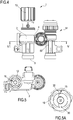
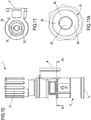
- the regulating device 1 comprises a body 2 provided with at least one inlet 3, an outlet 4 and an interception (or passage) area 5, as shown in Figures 1 , 3 , 4 , 7 , 8 and 10 .
- the inlet 3 is intended to be connected to a line so as to receive a fluid therefrom, whereas the outlet 4 is intended to be connected to a respective line so as to send a fluid thereto;the device is thus configured so as to enable a suitably regulated passage of fluid along a direction from the inlet to the outlet.
- the interception area 5 is inside the body 2 and it is interposed between the inlet and the outlet so as to connect the inlet and the outlet in such a way that the inlet and the outlet can be selectively set into fluid communication with each other.
- fluid generally refers to water in a heating or plumbing system.
- the inlet and the outlet constitute outward openings in the body of the device and they each have suitable means for connection to lines, pipes or other elements of plumbing systems; such connection means can be of a known type, for example threads, press fittings, etc.
- the device 1 further comprises a valve element 10 that is at least partially housed inside the body 2 and that is operatively active in the interception area 5.
- the valve element 10 is configured to operate in a plurality of operating configurations so as to vary the flow rate of fluid passing from the inlet 3 to the outlet 4, through the interception area 5, as a function of the difference in temperature between the perceived temperature of the fluid at said inlet and a reference temperature at which the valve element is configured.
- the plurality of operating configurations comprise at least:
- the device 1 is above all a limit temperature controller, in that it is capable of managing the flow rate passing through it, from the inlet to the outlet, proportionally to the difference between the temperature of the fluid at the inlet and a reference temperature;the latter constitutes a "limit" temperature, given that when the incoming fluid reaches this reference temperature, the valve element is brought into a closed configuration.
- the device 1 according to the present invention is structured so that in said closed configuration there is a residual flow rate of fluid transferred from the inlet to the outlet, and this residual flow rate is strictly greater than zero.
- the expression “as a function of the difference in temperature” can be understood as “proportionally to the difference in temperature”.
- the expression “perceived temperature of the fluid at the inlet” can be understood as the “the temperature of the fluid at the inlet as detected by the valve element”.
- said residual flow rate of fluid transferred from the inlet 3 to the outlet 4 in the closed configuration is comprised between 1 litre/hour and 10 litres/hour.
- Said residual flow rate of fluid transferred from the inlet to the outlet can be limited to a range comprised between 2 litres/hour and 8 litres/hour, or to a range comprised between 3 litres/hour and 6 litres/hour, or even to a range comprised between 3.5 litres/hour and 5 litres/hour.
- the valve element 10 preferably comprises a thermostatic valve 11 (or thermostatic element) inserted in the body and comprising a movable shutter 15 configured to move closer to and away from a passage section 20 defined in the interception area 5, so as to vary the flow rate of a fluid passing from the inlet 3 to the outlet 4 according to said plurality of operating configurations.
- a thermostatic valve 11 or thermostatic element
- a movable shutter 15 configured to move closer to and away from a passage section 20 defined in the interception area 5, so as to vary the flow rate of a fluid passing from the inlet 3 to the outlet 4 according to said plurality of operating configurations.
- the shutter 15 preferably moves closer to the passage section 20 upon a decrease in the difference between the perceived temperature of the fluid at the inlet 3 and the reference temperature, decreasing the flow rate, and it moves away from the passage section 20 upon an increase in the difference between the perceived temperature of the fluid at the inlet 3 and the reference temperature, increasing the flow rate.
- the leakage of fluid takes place between the shutter 15 and the passage section 20 and this leakage determines the passage of said residual flow rate of fluid from the inlet to the outlet.
- controlled leakage of fluid is understood as an intentional leakage of fluid, that is, leakage of a suitable amount of fluid. Essentially, said leakage ensures that the residual flow rate of fluid is transferred in each operating configuration of the valve element, and particularly in the closed configuration.
- the thermostatic valve 11 preferably comprises a temperature-sensitive thermostat 12.
- This thermostat 12 is configured to vary its dimensions as a function of the temperature it perceives.
- the thermostat can be of a known type, for example a wax-, gas- or liquid-type thermostat.
- the shutter 15 is preferably associated with or constrained to the thermostat 12.
- the thermostat 12 is preferably axially inserted in the body 2, in such a way as to occupy at least partially the interception area 5, and it modifies its own length as a function of the temperature of the fluid at the inlet 3.
- the thermostat increases in length upon an increase in the perceived temperature, bringing the shutter 15 closer to the passage section 20, and decreases in length upon a decrease in the perceived temperature, bringing the shutter 15 away from the passage section 20.
- the valve element 10 preferably comprises members for the selection of said reference temperature, so that when the fluid incoming to the inlet 3 reaches or exceeds this reference temperature, the valve element is brought into the closed configuration.
- the members for selecting the reference temperature can comprise a knob 13 that is active on the thermostat 12 to vary the axial position thereof inside the body of the device, so as to bring the shutter 15 closer to or away from the passage section, where the approaching movement of the shutter determines a lowering of the reference temperature and the distancing movement of the shutter determines an increase in the reference temperature.
- movement of the shutter away from the passage section requires greater thermal expansion in order to reach the closed configuration and therefore a greater increase in the temperature at the inlet.
- movement of the shutter closer to the passage section requires less thermal expansion in order to reach the closed configuration and therefore a lower increase in the temperature at the inlet.
- the device 1 thus works in the following manner: It is connected to a line which sends water to the inlet 3 and to an additional line which receives water from the outlet 4, and a reference temperature is also set, owing to the action of the knob for example.
- the valve element 10 is wet by the water incoming to the inlet 3 and it perceives the temperature thereof.
- the valve element operates in a given operating configuration according to the difference between the temperature of the water at the inlet and the reference temperature, that is, it allows a higher or lower flow rate of fluid to pass from the inlet 3 to the output 4.
- the thermostat 12 increases in length.
- the increase in the length of the thermostat determines the descent of the shutter 15 until it abuts against the passage section, that is, until the closed configuration is reached, and the closed configuration is maintained for temperatures at the inlet equal to or higher than the set reference temperature (which is therefore a "limit" temperature in all respects).
- the device 1 of the present invention comprises the passage of a residual flow rate of water, for example by means of leakage between the shutter and the passage section.
- the passage of the "residual flow rate" can be advantageously achieved by means of the example embodiment in Figures 4 to 8 , which comprises a structure of the shutter capable of realizing the controlled leakage.
- the various components of the device 1 are visible: the body 2, the inlet 3, the outlet 4, the interception area 5, the valve element 10, the thermostatic valve 11, the thermostat 12, the knob 13, the shutter 15 and the passage section 20.
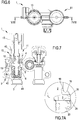
- the section appearing in Figure 7 shows the device in a partially open configuration. It is possible to note (see the detail in Figure 7A ) the axial distance existing between the shutter and the passage section, which enables the passage of a flow rate of water from the inlet to the outlet.
- the shutter 15 preferably has a substantially ring (or disc) shape and is positioned around the thermostat 12, preferably coaxially with respect to the longitudinal extension of the thermostat.
- the shutter preferably has a lower surface 16 facing the passage section 20 defined in the interception area 5 and preferably having a circular crown shape, and an upper surface 18 opposite the lower surface 16.
- the thermostat 12 is preferably positioned in the interception area 5 so as to pass through the passage section 20, leaving a preferably ring-shaped passage free between the thermostat and the inner walls of the body 2 of the device or of the valve element 10.
- the lower surface 16 moves away from the passage section 20 as the thermostat 12 decreases in length (upon the decrease in the perceived temperature), moves closer to the passage section 20 as the thermostat increases in length (upon the increase in the perceived temperature), and moves so as to abut on a perimeter surface 25 of the passage section 20 when the valve element is brought into the closed configuration.
- the perimeter surface 25 preferably has a ring shape and it extends in a plane substantially perpendicular to the longitudinal extension of the body of the device and the thermostat, that is, in a plane orthogonal to the direction of expansion and contraction of the thermostat.
- the perimeter surface 25 which extends around the passage section 20 constitutes a seat for the shutter, a seat on which the lower surface of the shutter abuts, at least partially, when the valve element is in the closed configuration.
- the lower surface 16 has at least one hollow portion 30 recessed from the lower surface (towards the upper surface 18), so that when the shutter is positioned so as to abut on the perimeter surface 25 of the passage section, that is, when the valve element is brought into the closed configuration, between the perimeter surface 25 and the hollow portion 30, a free channel 31 is realized in the passage section 20, through which the passage of said residual flow rate of fluid takes place from the inlet to the outlet of the device.
- the channel 31 is defined between the lower surface of the shutter and the passage section, although the shutter is actually abutting on the perimeter surface 25.
- the lower surface 16 of the shutter 15 can preferably have two hollow portions 30, for example diametrically opposed with respect to the thermostat around which the shutter is fastened;in this case, two channels 31 are realized for the passage of the fluid.
- the presence of the hollow portion 30 (or of a number of hollow portions) enables a passage of fluid, even if at the same time the resting of the lower surface 16 of the shutter 15 abutting on the passage section 20 is ensured in any case, given that the entire lower surface of the shutter, with the exception of the hollow portion (or of the hollow portions if there is more than one) can abut on the perimeter surface, and thus intercept the passage section.
- FIGS 5 and 5A show a ring-shaped shutter 15 arranged around the thermostat.
- Two hollow portions are realized along a diameter of the lower surface of the shutter and they extend from the outside towards the inside of the lower surface, to as far as the thermostat.
- the two hollow portions represent a removal of shutter material, starting from the lower surface towards the upper surface, that is, starting from the plane of the figures inwards.
- This section has been taken through a central plane of the device (as illustrated in Figure 6 ) and it thus intercepts the two hollow portions shown in Figures 5 and 5A .
- the lower surface of the shutter can have a plurality of hollow portions that are preferably evenly distributed on the lower surface.
- the lower surface of the shutter is preferably planar and/or smooth, with the exception of said at least one hollow portion (or of the hollow portions if there is more than one).
- the depth of said at least one hollow portion that is, the distance of the recess from the lower surface of the shutter, can be less than 3mm, or less than 2mm, or less than 1mm, or less than 0.5mm or less than 0.2mm.
- said leakage can be realized at additional points of the device and particularly at points in the interception area 5.
- the valve element 10 can be constituted by a thermostatic spindle, or a thermostatic cartridge, and comprise a containment structure 40 that houses the thermostatic valve 11, the knob 13 with the means for selecting the reference temperature (i.e., the stem active on the thermostat 12 and the retaining spring), and the thermostat 12 with the shutter 15.
- the containment structure 40 is inserted in the body 2 of the device, in such a way that the thermostatic valve proves to be correctly positioned inside the body, with the thermostat active in the interception area.
- One or more gaskets are present between the containment structure 40 and an inner wall 6 of the body 2 in order to enable proper mounting of the thermostatic spindle, or cartridge, in the body of the device.
- the device preferably comprises a gasket 41 interposed between the outside of the valve element 10 (for example, the structure 40 of said thermostatic spindle) and the inside of the body 2, and located in said interception area between the inlet 3 and the outlet 4.
- the leakage of fluid to realize said residual flow rate of fluid can take place between the outside of the valve element 10 and an inner wall of the body 2, and particularly it can take place in the absence of gaskets interposed between these two elements.
- the leakage can take place at said gasket 41; with this aim and by way of example, the gasket 41 can be undersized so as not to effect perfect sealing between the valve element and the body of the device and therefore enable the passage of the residual flow rate of fluid.
- valve element is inserted in the interception area with the containment structure 40 against the inner wall 6 of the body 2 of the device, and the passage section 20, in addition to being inside the body 2 is also inside the containment structure 40.
- the controlled leakage can be achieved by preventing the shutter, when it is abutting on the seat constituted by the perimeter surface of the passage section, from effecting complete sealing and by providing instead a seal that is not optimal and that enables a passage of fluid equal to said residual flow rate.
- the body of the device comprises a bypass line or passage extending between and connecting the inlet to the outlet and configured to ensure the transfer of said residual flow rate of fluid in each operating configuration of the valve element and particularly in the closed configuration.
- the bypass line is defined at or in proximity to the interception area.
- the bypass line is defined at or in proximity to the passage section.
- the bypass line is defined, within said body, at the thermostatic valve, particularly at the thermostat and/or shutter.
- the bypass line is configured to transfer fluid present immediately upstream of the thermostatic valve towards the outlet, with a flow rate equal to said residual flow rate of fluid.
- said residual flow rate of fluid, transferred from the inlet to the outlet, is present in each operating configuration of the valve element.
- the bypass line which is used for the passage of said residual flow rate, constitutes an alternative embodiment of said controlled leakage, regardless of the point inside the body in which the leakage takes place or the procedure for obtaining the leakage.
- the body 2 of the device is preferably made as a single piece or monobloc structure.
- the body 2 of the device is preferably obtained by means of a single casting process, preferably by casting a metal material, for example brass.
- FIG. 1 schematically illustrates the system by way of example.
- the heating system 100 comprises at least one radiant pipe 70 intended for floor installation and configured to heat a space.
- the radiant pipe 70 extends between an inlet end 71, which is intended to be fluidly connected with a source of high temperature fluid so as to receive high temperature fluid therefrom, and an outlet end 72, which is intended to be connected with a heat generator so as to admit low temperature fluid therein.
- the radiant pipe 70 comprises a coiled portion 75 configured to transmit radiant heat from the fluid, flowing therein, outwards.
- the source of high temperature fluid can be the delivery line of a boiler or a high temperature water circuit 101, and the low temperature return can be a return line 102 to the boiler.
- the inlet end 71 is preferably directly connected with the source of high temperature fluid, without the interposition of valves or regulators, that is, it is branched off directly from the high temperature circuit 101.
- the device 1 is preferably located downstream of the coiled portion 75 and upstream of the outlet end 72 of the radiant pipe so as to intercept the flow of fluid flowing in the pipe.
- the inlet 3 of the device 1 receives fluid coming from the coiled portion 75, the device 1 transmits a flow rate for this fluid to the outlet 4 based on the operating configuration of the valve element 10, and the outlet 4 is connected with the outlet end 72 of the radiant pipe 70.
- the heating system 100 is preferably a system for heating spaces and, in addition to the radiant floor pipe 70, it also comprises a high temperature part 90 of the system.ln this case, the high temperature part 90 of the system branches off directly from the high temperature water circuit 101, supplies one or more thermosiphons 91 and then returns directly into the return line 102 to the boiler.
- the system can comprise a number of branches and a number of portions, for example each one being intended for a different room inside a building or a residence.
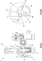
- the coiled portion 75 in a plan view, is preferably shaped in the form of a double spiral, so that the beginning 76 and the end 77 of this coiled portion prove to be contiguous with respect to each other, that is, close to each other, and outside of the double spiral itself.
- the double spiral comprises a first spiral 78, or outgoing spiral, extending from the beginning 76 of the coiled portion to a central point 80 of the coiled portion, and a second spiral 79, or return spiral, extending from the central point 80 to the end 77 of the coiled portion; the central point connects, and is shared by, the first spiral 78 and the second spiral 79.
- the first spiral 78 and the second spiral 79 are preferably arranged, in the double spiral, in such a way that they are interposed or alternated with respect to each other; this produces, from the outside to the inside of the double spiral, an alternation of coils and turns of the first spiral and the second spiral.
- the double spiral shape taken on by the coil 75 makes it possible to have the maximum temperature turn or coil (which is part of the first spiral 78, the outgoing spiral) outside the coil itself; alongside it, proceeding towards the inside of the coil, there is the minimum temperature turn or coil (that is, the last turn that is part of the second spiral 79, the return spiral).
- the minimum temperature turn or coil that is, the last turn that is part of the second spiral 79, the return spiral.
- the double spiral shape makes it possible to equilibrate the temperature (decreasing from the outside inwards) present in the outgoing spiral with the temperature (decreasing from the inside outwards) present in the return spiral, and to obtain the most even floor temperature distribution possible.
- the heating system 100 further comprises a thermostatic valve 50 for thermostatic control of a space, preferably a thermostatic head, located along the radiant pipe 70 at a point downstream of the regulating device 1.
- the thermostatic valve 50 for temperature control of a space is configured so as to enable the selection of a desired temperature for the space in which the heating system is installed and therefore to regulate the flow rate of fluid circulating in the radiant pipe 70 as a function of (or proportionally to) the difference between a temperature detected in the space and the desired temperature for the space.
- this embodiment comprises the use of both the device 1 and a thermostatic valve 50.ln fact, if the device 1 is in charge of managing the inflow of water into the radiant pipe 70 when the feed water is at high temperature, ensuring the correct temperature in the pipe and avoiding damage to the flooring, the user typically wants to be able to set and control the actual temperature present in the room in which the radiant pipe operates. In fact, comfort in the room is given by the possibility of managing the perceived room temperature and not by the temperature of the water circulating in the coil 75 (this latter temperature having a technical function related to the heat radiated for heating).
- two independent temperature controls are obtained: one control for the water in the radiant pipe, provided by the device 1, and one control for the space, by means of the thermostatic valve 50.
- Figures 1 to 8 show the device 1 combined with a valve 51 that can be thermostatically controlled and with which a thermostatic head 50 can be associated, directly mounted on the valve or in a remote position.
- the body 2 of the device 1 and the respective body 52 of the valve 51 that can be thermostatically controlled can be made as a single piece.
- the device 1 and the valve 51 that can be thermostatically controlled are housed inside a specific case 55 of a type that is known in the field.
- Figure 9 shows a different embodiment which provides for use of the regulating device 1 inside a heating plant 95 that is inserted in a case or cabinet and for example built into a wall compartment, according to procedures that are known in the field.
- the heating plant comprises numerous elements, including pipes, collectors, valves, mounting brackets, etc. These elements are in charge of managing numerous portions of a heating system, which can be of a mixed type and comprise portions or branches operating at high temperatures (with thermosiphons) as well as portions or branches operating at low temperatures (with floor pipes).
- Figures 10 and 11 show the structure of the device 1 contained in the heating plant 95.
- the device is identical to the device shown in Figures 1-8 and as can be seen in the section appearing in Figures 11 and 11A , it has a shutter with hollow portions which makes it possible to realize the leakage owing to which the residual flow rate is transferred from the inlet to the outlet when the device is in the closed configuration.
- the device 1 constituting the object of the present invention operates inside cases or closed boxes, in which an issue arises, as described above and as is known in the field, that is, the problem of the overheating of the various elements, including the regulating device for controlling the limit temperature.
- the solution underlying the present invention makes it possible to achieve proper operation of the device even under these conditions and this is possible owing to the residual flow rate of fluid, which passes even in the closed configuration. Although it is preferably a low rate, for example 3-5 litres/hour, this residual flow rate is sufficient to "empty" the inner part of the body (that is, the interception area) near the temperature-sensitive valve element even when the latter is closed. Essentially, even with the device being closed a passage of fluid is maintained, enabling the circulation of a small amount of water, rather than having it stagnate at the inlet, exposing it to overheating phenomena typical of the environment found inside cases and heating plants.
- the residual flow rate maintained by the device even in the closed configuration - for example by means of said leakage, which determines a passage through the device of water leaving the radiant pipe (and as a result the admittance of an equal amount of high temperature water) - is such that it does not affect proper operation of the system.
- the regulating device can in any case be considered closed even if the residual flow rate is maintained.
- the residual flow rate is preferably a low rate, so as not to modify the overall temperature in the floor pipe and not to cause malfunctioning in the system or in the control part;in essence, there is no impact on the operation of the system, but only local benefits related to the operation of the regulating device 1. This is the case even when the heating process carried out by the radiant floor pipe is stopped. In that case, the residual flow rate does not have any concrete effects relating to heating the floor or on the room containing the pipe.
- thermostatic valve 50 in combination with the device 1, prevents any undesirable effects due to the passage of the residual flow rate in the closed configuration. This is because even if the residual flow rate can in theory increase the radiant effect, in any case the thermostatic valve takes care of keeping regulation of the temperature desired in the space active.
- the method for regulating heating systems which constitutes an object of the present invention, can be implemented preferably but not exclusively by a device 1 of the type described hereinabove. In this case, the method can substantially coincide with the operating procedure and the installation of a heating system that includes the regulating device 1.
- This method comprises arranging a radiant pipe, as described above, and connecting a regulating device 1 thereto according to the procedures described hereinabove.
- the method then comprises a step of circulating a fluid in said radiant pipe, in which the flow rate of fluid passing from the inlet to the outlet of the regulating device, through the interception area, is a function of the difference in temperature between the perceived temperature of the fluid at the inlet and the reference temperature at which the valve element is configured;it follows that the flow rate passing from the inlet to the outlet of the regulating device and conveyed towards the outlet end of the radiant pipe is equal to the incoming flow rate at the inlet end of the radiant pipe.
- the method further comprises that the step of circulating a fluid in said radiant pipe comprises a step of maintaining a residual flow rate, greater than zero, of fluid transferred from the inlet to the outlet of the regulating device when the valve element is in the closed configuration.
- the residual flow rate of fluid is preferably comprised between 2 litres/hour and 8 litres/hour or comprised between 3 litres/hour and 6 litres/hour or comprised between 3.5 litres/hour and 5 litres /hour.
- the step of maintaining the residual flow rate is the step that makes it possible to distance the water stopped at the inlet of the device 1 before it can overheat and to have new water reach it, from the end of the radiant pipe, so that the valve element detects the correct temperature of the water present precisely at the end of the pipe.
- step of maintaining the residual flow rate must be carried out in the proper area of the device, that is, in the proximity of the valve element (that is, around or in the proximity of the thermostat and the shutter), where the device perceives the temperature and where in the prior art the "lockout" problem takes place with the device being closed.
- the device of the present invention makes it possible to effectively connect a radiant floor pipe to a high temperature circuit, enabling proper management of the operating temperatures and of the flows inside the pipe. Furthermore, the device of the present invention is capable of operating correctly inside heating plants or in proximity to components of a heating system operating at high temperatures.
- the device of the present invention is also characterized by a high degree of versatility and it is capable of adapting to a large number and many different types of heating systems.
- Application of the invention is particularly advantageous when one wants to be able to realize a new portion of a system with floor heating, while also using an already existing system that operates at high temperatures, for example because it is a system that uses radiators or thermosiphons.
- the device of the present invention is characterized by a high level of operating reliability, by less susceptibility to damage and malfunctioning and it can offer simple and rapid maintenance.
- the device of the present invention is characterized by a competitive cost and by a simple and rational structure.
Landscapes
- Engineering & Computer Science (AREA)
- Physics & Mathematics (AREA)
- Thermal Sciences (AREA)
- Chemical & Material Sciences (AREA)
- Combustion & Propulsion (AREA)
- Mechanical Engineering (AREA)
- General Engineering & Computer Science (AREA)
- General Physics & Mathematics (AREA)
- Automation & Control Theory (AREA)
- Fluid Mechanics (AREA)
- Steam Or Hot-Water Central Heating Systems (AREA)
- Details Of Valves (AREA)
Priority Applications (3)
| Application Number | Priority Date | Filing Date | Title |
|---|---|---|---|
| SI201830129T SI3358263T1 (sl) | 2017-01-30 | 2018-01-23 | Naprava in postopek za regulacijo ogrevalnih sistemov |
| RS20201287A RS60980B1 (sr) | 2017-01-30 | 2018-01-23 | Uređaj i postupak za regulisanje sistema za grejanje |
| PL18152988T PL3358263T3 (pl) | 2017-01-30 | 2018-01-23 | Urządzenie i sposób regulacji układów grzewczych |
Applications Claiming Priority (1)
| Application Number | Priority Date | Filing Date | Title |
|---|---|---|---|
| IT201700009800 | 2017-01-30 |
Publications (2)
| Publication Number | Publication Date |
|---|---|
| EP3358263A1 EP3358263A1 (en) | 2018-08-08 |
| EP3358263B1 true EP3358263B1 (en) | 2020-09-02 |
Family
ID=61024600
Family Applications (1)
| Application Number | Title | Priority Date | Filing Date |
|---|---|---|---|
| EP18152988.4A Active EP3358263B1 (en) | 2017-01-30 | 2018-01-23 | Device and method for regulating heating systems |
Country Status (7)
| Country | Link |
|---|---|
| EP (1) | EP3358263B1 (ru) |
| CN (1) | CN108375103A (ru) |
| DK (1) | DK3358263T3 (ru) |
| EA (1) | EA036897B1 (ru) |
| PL (1) | PL3358263T3 (ru) |
| RS (1) | RS60980B1 (ru) |
| SI (1) | SI3358263T1 (ru) |
Families Citing this family (2)
| Publication number | Priority date | Publication date | Assignee | Title |
|---|---|---|---|---|
| CN114110720B (zh) * | 2021-11-25 | 2022-12-02 | 江西渥泰环保科技有限公司 | 一种基于物联网信息数据的家庭水屋分时控制装置 |
| CN114576699B (zh) * | 2022-04-05 | 2023-05-30 | 台州半城暖通科技有限公司 | 一种卫生间多方式供暖阀门 |
Family Cites Families (15)
| Publication number | Priority date | Publication date | Assignee | Title |
|---|---|---|---|---|
| CH639737A5 (de) * | 1979-04-18 | 1983-11-30 | Hydrowatt Syst | Abdichtung an einer kolben-zylinder-anordnung. |
| DE29823960U1 (de) * | 1998-07-27 | 2000-02-24 | Neheim Goeke & Co Metall | Ventil für Warmwasseranlagen |
| GB2431452A (en) * | 2005-10-18 | 2007-04-25 | Christopher Alan Checklin | Device for water heater |
| WO2007090405A2 (en) * | 2006-02-10 | 2007-08-16 | Danfoss A/S | Control of a system with a large thermal capacity |
| DE102006052296A1 (de) * | 2006-09-04 | 2008-03-06 | Otto Egelhof Gmbh & Co. Kg | Thermostatisches Ventil zur Regelung eines Massenstromes |
| CN101784974B (zh) * | 2007-08-21 | 2013-01-02 | 奥托.埃杰尔霍夫两合公司 | 阀元件以及用于调节质量流的恒温调节装置 |
| GB0716470D0 (en) * | 2007-08-23 | 2007-10-03 | Tomlinson Andrew P | Flow control |
| CN100578056C (zh) * | 2008-07-09 | 2010-01-06 | 邵柯璇 | 三通智能电控球阀 |
| DE102009004319A1 (de) * | 2009-01-10 | 2010-07-22 | Henry Klein | Verfahren, Computerprogramm und Regelgerät für einen temperaturbasierten hydraulischen Abgleich |
| CN201589342U (zh) * | 2009-08-20 | 2010-09-22 | 浙江灵铭管道科技有限公司 | 调节阀有开度指示的分水器 |
| DE102010055483B4 (de) * | 2010-12-22 | 2013-06-06 | Danfoss A/S | Ventil, insbesondere Heizkörperventil |
| GB2505396B (en) * | 2012-06-22 | 2015-07-15 | Thermosave Ltd | Flow control |
| JP6884747B2 (ja) * | 2015-07-09 | 2021-06-09 | ノードソン コーポレーションNordson Corporation | 加熱食品材料を搬送して分注するシステム |
| DE202015006660U1 (de) * | 2015-09-22 | 2016-12-23 | Gebr. Kemper Gmbh + Co. Kg Metallwerke | Absperrventil für ein Heizungssystem |
| CN105737255B (zh) * | 2016-04-06 | 2018-08-17 | 青岛瑞雪兆散热器有限公司 | 一种智能暖气阀门 |
-
2018
- 2018-01-22 EA EA201890116A patent/EA036897B1/ru unknown
- 2018-01-23 EP EP18152988.4A patent/EP3358263B1/en active Active
- 2018-01-23 RS RS20201287A patent/RS60980B1/sr unknown
- 2018-01-23 DK DK18152988.4T patent/DK3358263T3/da active
- 2018-01-23 PL PL18152988T patent/PL3358263T3/pl unknown
- 2018-01-23 SI SI201830129T patent/SI3358263T1/sl unknown
- 2018-01-29 CN CN201810085022.0A patent/CN108375103A/zh active Pending
Non-Patent Citations (1)
| Title |
|---|
| None * |
Also Published As
| Publication number | Publication date |
|---|---|
| RS60980B1 (sr) | 2020-11-30 |
| DK3358263T3 (da) | 2020-10-26 |
| EA201890116A2 (ru) | 2018-07-31 |
| SI3358263T1 (sl) | 2020-12-31 |
| EP3358263A1 (en) | 2018-08-08 |
| EA036897B1 (ru) | 2021-01-13 |
| CN108375103A (zh) | 2018-08-07 |
| PL3358263T3 (pl) | 2021-03-08 |
| EA201890116A3 (ru) | 2018-10-31 |
Similar Documents
| Publication | Publication Date | Title |
|---|---|---|
| EP3358263B1 (en) | Device and method for regulating heating systems | |
| US9110477B2 (en) | Over-temperature protection for flowing fluid systems | |
| US9316412B2 (en) | High capacity water heater | |
| RU2508510C1 (ru) | Система регулирования распределения текучей среды | |
| KR101040692B1 (ko) | 차압정보를 이용한 비례유량조절시스템 | |
| US20070108304A1 (en) | Hot water supply device | |
| KR101020872B1 (ko) | 자동온도조절밸브 | |
| US20110089249A1 (en) | Thermostatic mixing valve with pressure reducing element | |
| CA3203110A1 (en) | A hydraulic unit | |
| US20180321698A1 (en) | Thermal balancing valve and system using the same | |
| EP3411633B1 (en) | Water systems | |
| GB2568947A (en) | A combi-boiler device | |
| KR102160305B1 (ko) | 급탕라인을 열원으로하는 급탕 난방 통합 배관시스템 | |
| GB2549601A (en) | Water heater | |
| US4599992A (en) | Anticipatory thermostat with reset for domestic hydronic boiler control | |
| US20160004264A1 (en) | Thermal balancing valve and system using the same | |
| NL2015440B1 (en) | Satellite for central heating or for teleheating with multifunction presettings. | |
| KR102183721B1 (ko) | 저온 열원공급수 유입을 제어하는 급탕 난방 통합 배관시스템 | |
| WO2020183179A1 (en) | Thermostatic timeflow control cartridge | |
| US20080223947A1 (en) | Steam heating system with new steam baseboard | |
| NL2020522B1 (en) | Improved satellite plumbing unit | |
| KR102322552B1 (ko) | 냉난방용 비례제어밸브 | |
| KR20160150313A (ko) | 지역 및 중앙 난방에 적용되는 난방 및 온수 공급 장치 및 그 제어 방법 | |
| GB2505396A (en) | Apparatus to control a flow of heated water from a boiler to a water outlet | |
| GB2342429A (en) | Flow control for boiler of central heating/hot water system |
Legal Events
| Date | Code | Title | Description |
|---|---|---|---|
| PUAI | Public reference made under article 153(3) epc to a published international application that has entered the european phase |
Free format text: ORIGINAL CODE: 0009012 |
|
| STAA | Information on the status of an ep patent application or granted ep patent |
Free format text: STATUS: THE APPLICATION HAS BEEN PUBLISHED |
|
| AK | Designated contracting states |
Kind code of ref document: A1 Designated state(s): AL AT BE BG CH CY CZ DE DK EE ES FI FR GB GR HR HU IE IS IT LI LT LU LV MC MK MT NL NO PL PT RO RS SE SI SK SM TR |
|
| AX | Request for extension of the european patent |
Extension state: BA ME |
|
| STAA | Information on the status of an ep patent application or granted ep patent |
Free format text: STATUS: REQUEST FOR EXAMINATION WAS MADE |
|
| 17P | Request for examination filed |
Effective date: 20190204 |
|
| RBV | Designated contracting states (corrected) |
Designated state(s): AL AT BE BG CH CY CZ DE DK EE ES FI FR GB GR HR HU IE IS IT LI LT LU LV MC MK MT NL NO PL PT RO RS SE SI SK SM TR |
|
| GRAP | Despatch of communication of intention to grant a patent |
Free format text: ORIGINAL CODE: EPIDOSNIGR1 |
|
| STAA | Information on the status of an ep patent application or granted ep patent |
Free format text: STATUS: GRANT OF PATENT IS INTENDED |
|
| INTG | Intention to grant announced |
Effective date: 20200417 |
|
| GRAS | Grant fee paid |
Free format text: ORIGINAL CODE: EPIDOSNIGR3 |
|
| GRAA | (expected) grant |
Free format text: ORIGINAL CODE: 0009210 |
|
| STAA | Information on the status of an ep patent application or granted ep patent |
Free format text: STATUS: THE PATENT HAS BEEN GRANTED |
|
| AK | Designated contracting states |
Kind code of ref document: B1 Designated state(s): AL AT BE BG CH CY CZ DE DK EE ES FI FR GB GR HR HU IE IS IT LI LT LU LV MC MK MT NL NO PL PT RO RS SE SI SK SM TR |
|
| REG | Reference to a national code |
Ref country code: GB Ref legal event code: FG4D |
|
| REG | Reference to a national code |
Ref country code: AT Ref legal event code: REF Ref document number: 1309276 Country of ref document: AT Kind code of ref document: T Effective date: 20200915 Ref country code: CH Ref legal event code: EP |
|
| REG | Reference to a national code |
Ref country code: DE Ref legal event code: R096 Ref document number: 602018007339 Country of ref document: DE |
|
| REG | Reference to a national code |
Ref country code: CH Ref legal event code: NV Representative=s name: ING. ALESSANDRO GALASSI C/O PGA S.P.A., MILANO, CH Ref country code: IE Ref legal event code: FG4D |
|
| REG | Reference to a national code |
Ref country code: FI Ref legal event code: FGE |
|
| REG | Reference to a national code |
Ref country code: DK Ref legal event code: T3 Effective date: 20201023 |
|
| REG | Reference to a national code |
Ref country code: SE Ref legal event code: TRGR |
|
| REG | Reference to a national code |
Ref country code: SK Ref legal event code: T3 Ref document number: E 35488 Country of ref document: SK |
|
| REG | Reference to a national code |
Ref country code: NO Ref legal event code: T2 Effective date: 20200902 |
|
| REG | Reference to a national code |
Ref country code: LT Ref legal event code: MG4D |
|
| PG25 | Lapsed in a contracting state [announced via postgrant information from national office to epo] |
Ref country code: BG Free format text: LAPSE BECAUSE OF FAILURE TO SUBMIT A TRANSLATION OF THE DESCRIPTION OR TO PAY THE FEE WITHIN THE PRESCRIBED TIME-LIMIT Effective date: 20201202 Ref country code: GR Free format text: LAPSE BECAUSE OF FAILURE TO SUBMIT A TRANSLATION OF THE DESCRIPTION OR TO PAY THE FEE WITHIN THE PRESCRIBED TIME-LIMIT Effective date: 20201203 Ref country code: HR Free format text: LAPSE BECAUSE OF FAILURE TO SUBMIT A TRANSLATION OF THE DESCRIPTION OR TO PAY THE FEE WITHIN THE PRESCRIBED TIME-LIMIT Effective date: 20200902 Ref country code: LT Free format text: LAPSE BECAUSE OF FAILURE TO SUBMIT A TRANSLATION OF THE DESCRIPTION OR TO PAY THE FEE WITHIN THE PRESCRIBED TIME-LIMIT Effective date: 20200902 |
|
| REG | Reference to a national code |
Ref country code: NL Ref legal event code: MP Effective date: 20200902 |
|
| PG25 | Lapsed in a contracting state [announced via postgrant information from national office to epo] |
Ref country code: LV Free format text: LAPSE BECAUSE OF FAILURE TO SUBMIT A TRANSLATION OF THE DESCRIPTION OR TO PAY THE FEE WITHIN THE PRESCRIBED TIME-LIMIT Effective date: 20200902 |
|
| PG25 | Lapsed in a contracting state [announced via postgrant information from national office to epo] |
Ref country code: SM Free format text: LAPSE BECAUSE OF FAILURE TO SUBMIT A TRANSLATION OF THE DESCRIPTION OR TO PAY THE FEE WITHIN THE PRESCRIBED TIME-LIMIT Effective date: 20200902 Ref country code: PT Free format text: LAPSE BECAUSE OF FAILURE TO SUBMIT A TRANSLATION OF THE DESCRIPTION OR TO PAY THE FEE WITHIN THE PRESCRIBED TIME-LIMIT Effective date: 20210104 Ref country code: EE Free format text: LAPSE BECAUSE OF FAILURE TO SUBMIT A TRANSLATION OF THE DESCRIPTION OR TO PAY THE FEE WITHIN THE PRESCRIBED TIME-LIMIT Effective date: 20200902 |
|
| PGFP | Annual fee paid to national office [announced via postgrant information from national office to epo] |
Ref country code: CH Payment date: 20210122 Year of fee payment: 4 Ref country code: RO Payment date: 20210112 Year of fee payment: 4 |
|
| PG25 | Lapsed in a contracting state [announced via postgrant information from national office to epo] |
Ref country code: AL Free format text: LAPSE BECAUSE OF FAILURE TO SUBMIT A TRANSLATION OF THE DESCRIPTION OR TO PAY THE FEE WITHIN THE PRESCRIBED TIME-LIMIT Effective date: 20200902 Ref country code: ES Free format text: LAPSE BECAUSE OF FAILURE TO SUBMIT A TRANSLATION OF THE DESCRIPTION OR TO PAY THE FEE WITHIN THE PRESCRIBED TIME-LIMIT Effective date: 20200902 Ref country code: IS Free format text: LAPSE BECAUSE OF FAILURE TO SUBMIT A TRANSLATION OF THE DESCRIPTION OR TO PAY THE FEE WITHIN THE PRESCRIBED TIME-LIMIT Effective date: 20210102 |
|
| PGFP | Annual fee paid to national office [announced via postgrant information from national office to epo] |
Ref country code: SI Payment date: 20210104 Year of fee payment: 4 Ref country code: RS Payment date: 20210104 Year of fee payment: 4 |
|
| REG | Reference to a national code |
Ref country code: DE Ref legal event code: R097 Ref document number: 602018007339 Country of ref document: DE |
|
| PGFP | Annual fee paid to national office [announced via postgrant information from national office to epo] |
Ref country code: SK Payment date: 20210105 Year of fee payment: 4 |
|
| PLBE | No opposition filed within time limit |
Free format text: ORIGINAL CODE: 0009261 |
|
| STAA | Information on the status of an ep patent application or granted ep patent |
Free format text: STATUS: NO OPPOSITION FILED WITHIN TIME LIMIT |
|
| 26N | No opposition filed |
Effective date: 20210603 |
|
| PG25 | Lapsed in a contracting state [announced via postgrant information from national office to epo] |
Ref country code: MC Free format text: LAPSE BECAUSE OF FAILURE TO SUBMIT A TRANSLATION OF THE DESCRIPTION OR TO PAY THE FEE WITHIN THE PRESCRIBED TIME-LIMIT Effective date: 20200902 |
|
| PG25 | Lapsed in a contracting state [announced via postgrant information from national office to epo] |
Ref country code: LU Free format text: LAPSE BECAUSE OF NON-PAYMENT OF DUE FEES Effective date: 20210123 |
|
| REG | Reference to a national code |
Ref country code: BE Ref legal event code: MM Effective date: 20210131 |
|
| PG25 | Lapsed in a contracting state [announced via postgrant information from national office to epo] |
Ref country code: FR Free format text: LAPSE BECAUSE OF NON-PAYMENT OF DUE FEES Effective date: 20210131 |
|
| PG25 | Lapsed in a contracting state [announced via postgrant information from national office to epo] |
Ref country code: IE Free format text: LAPSE BECAUSE OF NON-PAYMENT OF DUE FEES Effective date: 20210123 |
|
| PG25 | Lapsed in a contracting state [announced via postgrant information from national office to epo] |
Ref country code: BE Free format text: LAPSE BECAUSE OF NON-PAYMENT OF DUE FEES Effective date: 20210131 |
|
| REG | Reference to a national code |
Ref country code: AT Ref legal event code: UEP Ref document number: 1309276 Country of ref document: AT Kind code of ref document: T Effective date: 20200902 |
|
| REG | Reference to a national code |
Ref country code: CH Ref legal event code: PL |
|
| REG | Reference to a national code |
Ref country code: SK Ref legal event code: MM4A Ref document number: E 35488 Country of ref document: SK Effective date: 20220123 |
|
| GBPC | Gb: european patent ceased through non-payment of renewal fee |
Effective date: 20220123 |
|
| PG25 | Lapsed in a contracting state [announced via postgrant information from national office to epo] |
Ref country code: SK Free format text: LAPSE BECAUSE OF NON-PAYMENT OF DUE FEES Effective date: 20220123 Ref country code: RO Free format text: LAPSE BECAUSE OF NON-PAYMENT OF DUE FEES Effective date: 20220123 Ref country code: GB Free format text: LAPSE BECAUSE OF NON-PAYMENT OF DUE FEES Effective date: 20220123 |
|
| PG25 | Lapsed in a contracting state [announced via postgrant information from national office to epo] |
Ref country code: SI Free format text: LAPSE BECAUSE OF NON-PAYMENT OF DUE FEES Effective date: 20220124 Ref country code: RS Free format text: LAPSE BECAUSE OF NON-PAYMENT OF DUE FEES Effective date: 20220123 |
|
| REG | Reference to a national code |
Ref country code: SI Ref legal event code: KO00 Effective date: 20220930 |
|
| PG25 | Lapsed in a contracting state [announced via postgrant information from national office to epo] |
Ref country code: LI Free format text: LAPSE BECAUSE OF NON-PAYMENT OF DUE FEES Effective date: 20220131 Ref country code: CH Free format text: LAPSE BECAUSE OF NON-PAYMENT OF DUE FEES Effective date: 20220131 |
|
| PGFP | Annual fee paid to national office [announced via postgrant information from national office to epo] |
Ref country code: NO Payment date: 20230119 Year of fee payment: 6 Ref country code: DK Payment date: 20230126 Year of fee payment: 6 |
|
| PGFP | Annual fee paid to national office [announced via postgrant information from national office to epo] |
Ref country code: SE Payment date: 20230124 Year of fee payment: 6 Ref country code: IT Payment date: 20230118 Year of fee payment: 6 |
|
| PG25 | Lapsed in a contracting state [announced via postgrant information from national office to epo] |
Ref country code: NL Free format text: LAPSE BECAUSE OF NON-PAYMENT OF DUE FEES Effective date: 20200923 Ref country code: CY Free format text: LAPSE BECAUSE OF FAILURE TO SUBMIT A TRANSLATION OF THE DESCRIPTION OR TO PAY THE FEE WITHIN THE PRESCRIBED TIME-LIMIT Effective date: 20200902 |
|
| P01 | Opt-out of the competence of the unified patent court (upc) registered |
Effective date: 20230529 |
|
| PG25 | Lapsed in a contracting state [announced via postgrant information from national office to epo] |
Ref country code: HU Free format text: LAPSE BECAUSE OF FAILURE TO SUBMIT A TRANSLATION OF THE DESCRIPTION OR TO PAY THE FEE WITHIN THE PRESCRIBED TIME-LIMIT; INVALID AB INITIO Effective date: 20180123 |
|
| PGFP | Annual fee paid to national office [announced via postgrant information from national office to epo] |
Ref country code: FI Payment date: 20231228 Year of fee payment: 7 |
|
| PGFP | Annual fee paid to national office [announced via postgrant information from national office to epo] |
Ref country code: PL Payment date: 20231228 Year of fee payment: 7 |
|
| PGFP | Annual fee paid to national office [announced via postgrant information from national office to epo] |
Ref country code: AT Payment date: 20240118 Year of fee payment: 7 |
|
| PG25 | Lapsed in a contracting state [announced via postgrant information from national office to epo] |
Ref country code: MK Free format text: LAPSE BECAUSE OF FAILURE TO SUBMIT A TRANSLATION OF THE DESCRIPTION OR TO PAY THE FEE WITHIN THE PRESCRIBED TIME-LIMIT Effective date: 20200902 |
|
| PGFP | Annual fee paid to national office [announced via postgrant information from national office to epo] |
Ref country code: DE Payment date: 20240129 Year of fee payment: 7 Ref country code: CZ Payment date: 20240104 Year of fee payment: 7 |