EP3357879A1 - Élément de distribution de gaz destiné à être utilisé dans la fabrication de semi-conducteur et procédé de fabrication d'un élément de distribution de gaz - Google Patents
Élément de distribution de gaz destiné à être utilisé dans la fabrication de semi-conducteur et procédé de fabrication d'un élément de distribution de gaz Download PDFInfo
- Publication number
- EP3357879A1 EP3357879A1 EP17154977.7A EP17154977A EP3357879A1 EP 3357879 A1 EP3357879 A1 EP 3357879A1 EP 17154977 A EP17154977 A EP 17154977A EP 3357879 A1 EP3357879 A1 EP 3357879A1
- Authority
- EP
- European Patent Office
- Prior art keywords
- gas
- wall
- opening
- quartz glass
- inner contour
- Prior art date
- Legal status (The legal status is an assumption and is not a legal conclusion. Google has not performed a legal analysis and makes no representation as to the accuracy of the status listed.)
- Withdrawn
Links
Images

Classifications
-
- C—CHEMISTRY; METALLURGY
- C03—GLASS; MINERAL OR SLAG WOOL
- C03C—CHEMICAL COMPOSITION OF GLASSES, GLAZES OR VITREOUS ENAMELS; SURFACE TREATMENT OF GLASS; SURFACE TREATMENT OF FIBRES OR FILAMENTS MADE FROM GLASS, MINERALS OR SLAGS; JOINING GLASS TO GLASS OR OTHER MATERIALS
- C03C23/00—Other surface treatment of glass not in the form of fibres or filaments
- C03C23/0005—Other surface treatment of glass not in the form of fibres or filaments by irradiation
- C03C23/0025—Other surface treatment of glass not in the form of fibres or filaments by irradiation by a laser beam
-
- B—PERFORMING OPERATIONS; TRANSPORTING
- B23—MACHINE TOOLS; METAL-WORKING NOT OTHERWISE PROVIDED FOR
- B23K—SOLDERING OR UNSOLDERING; WELDING; CLADDING OR PLATING BY SOLDERING OR WELDING; CUTTING BY APPLYING HEAT LOCALLY, e.g. FLAME CUTTING; WORKING BY LASER BEAM
- B23K26/00—Working by laser beam, e.g. welding, cutting or boring
- B23K26/02—Positioning or observing the workpiece, e.g. with respect to the point of impact; Aligning, aiming or focusing the laser beam
- B23K26/06—Shaping the laser beam, e.g. by masks or multi-focusing
- B23K26/062—Shaping the laser beam, e.g. by masks or multi-focusing by direct control of the laser beam
- B23K26/0622—Shaping the laser beam, e.g. by masks or multi-focusing by direct control of the laser beam by shaping pulses
- B23K26/0624—Shaping the laser beam, e.g. by masks or multi-focusing by direct control of the laser beam by shaping pulses using ultrashort pulses, i.e. pulses of 1ns or less
-
- B—PERFORMING OPERATIONS; TRANSPORTING
- B23—MACHINE TOOLS; METAL-WORKING NOT OTHERWISE PROVIDED FOR
- B23K—SOLDERING OR UNSOLDERING; WELDING; CLADDING OR PLATING BY SOLDERING OR WELDING; CUTTING BY APPLYING HEAT LOCALLY, e.g. FLAME CUTTING; WORKING BY LASER BEAM
- B23K26/00—Working by laser beam, e.g. welding, cutting or boring
- B23K26/36—Removing material
- B23K26/38—Removing material by boring or cutting
- B23K26/382—Removing material by boring or cutting by boring
- B23K26/389—Removing material by boring or cutting by boring of fluid openings, e.g. nozzles, jets
-
- B—PERFORMING OPERATIONS; TRANSPORTING
- B23—MACHINE TOOLS; METAL-WORKING NOT OTHERWISE PROVIDED FOR
- B23K—SOLDERING OR UNSOLDERING; WELDING; CLADDING OR PLATING BY SOLDERING OR WELDING; CUTTING BY APPLYING HEAT LOCALLY, e.g. FLAME CUTTING; WORKING BY LASER BEAM
- B23K26/00—Working by laser beam, e.g. welding, cutting or boring
- B23K26/36—Removing material
- B23K26/40—Removing material taking account of the properties of the material involved
- B23K26/402—Removing material taking account of the properties of the material involved involving non-metallic material, e.g. isolators
-
- C—CHEMISTRY; METALLURGY
- C03—GLASS; MINERAL OR SLAG WOOL
- C03C—CHEMICAL COMPOSITION OF GLASSES, GLAZES OR VITREOUS ENAMELS; SURFACE TREATMENT OF GLASS; SURFACE TREATMENT OF FIBRES OR FILAMENTS MADE FROM GLASS, MINERALS OR SLAGS; JOINING GLASS TO GLASS OR OTHER MATERIALS
- C03C15/00—Surface treatment of glass, not in the form of fibres or filaments, by etching
-
- C—CHEMISTRY; METALLURGY
- C03—GLASS; MINERAL OR SLAG WOOL
- C03C—CHEMICAL COMPOSITION OF GLASSES, GLAZES OR VITREOUS ENAMELS; SURFACE TREATMENT OF GLASS; SURFACE TREATMENT OF FIBRES OR FILAMENTS MADE FROM GLASS, MINERALS OR SLAGS; JOINING GLASS TO GLASS OR OTHER MATERIALS
- C03C23/00—Other surface treatment of glass not in the form of fibres or filaments
- C03C23/007—Other surface treatment of glass not in the form of fibres or filaments by thermal treatment
-
- C—CHEMISTRY; METALLURGY
- C03—GLASS; MINERAL OR SLAG WOOL
- C03C—CHEMICAL COMPOSITION OF GLASSES, GLAZES OR VITREOUS ENAMELS; SURFACE TREATMENT OF GLASS; SURFACE TREATMENT OF FIBRES OR FILAMENTS MADE FROM GLASS, MINERALS OR SLAGS; JOINING GLASS TO GLASS OR OTHER MATERIALS
- C03C3/00—Glass compositions
- C03C3/04—Glass compositions containing silica
- C03C3/06—Glass compositions containing silica with more than 90% silica by weight, e.g. quartz
-
- C—CHEMISTRY; METALLURGY
- C23—COATING METALLIC MATERIAL; COATING MATERIAL WITH METALLIC MATERIAL; CHEMICAL SURFACE TREATMENT; DIFFUSION TREATMENT OF METALLIC MATERIAL; COATING BY VACUUM EVAPORATION, BY SPUTTERING, BY ION IMPLANTATION OR BY CHEMICAL VAPOUR DEPOSITION, IN GENERAL; INHIBITING CORROSION OF METALLIC MATERIAL OR INCRUSTATION IN GENERAL
- C23C—COATING METALLIC MATERIAL; COATING MATERIAL WITH METALLIC MATERIAL; SURFACE TREATMENT OF METALLIC MATERIAL BY DIFFUSION INTO THE SURFACE, BY CHEMICAL CONVERSION OR SUBSTITUTION; COATING BY VACUUM EVAPORATION, BY SPUTTERING, BY ION IMPLANTATION OR BY CHEMICAL VAPOUR DEPOSITION, IN GENERAL
- C23C16/00—Chemical coating by decomposition of gaseous compounds, without leaving reaction products of surface material in the coating, i.e. chemical vapour deposition [CVD] processes
- C23C16/44—Chemical coating by decomposition of gaseous compounds, without leaving reaction products of surface material in the coating, i.e. chemical vapour deposition [CVD] processes characterised by the method of coating
- C23C16/453—Chemical coating by decomposition of gaseous compounds, without leaving reaction products of surface material in the coating, i.e. chemical vapour deposition [CVD] processes characterised by the method of coating passing the reaction gases through burners or torches, e.g. atmospheric pressure CVD
-
- C—CHEMISTRY; METALLURGY
- C03—GLASS; MINERAL OR SLAG WOOL
- C03C—CHEMICAL COMPOSITION OF GLASSES, GLAZES OR VITREOUS ENAMELS; SURFACE TREATMENT OF GLASS; SURFACE TREATMENT OF FIBRES OR FILAMENTS MADE FROM GLASS, MINERALS OR SLAGS; JOINING GLASS TO GLASS OR OTHER MATERIALS
- C03C2201/00—Glass compositions
- C03C2201/02—Pure silica glass, e.g. pure fused quartz
Definitions
- the invention relates to a method for producing a gas distribution element having a plurality of gas nozzles for use in semiconductor production, by providing a base body of quartz glass with at least one wall, defining a desired position and a desired inner contour for each of the gas nozzles, and generating a through opening in the wall at the desired position and with the desired inner contour of the respective gas nozzle.
- the invention relates to a gas distribution element for use in semiconductor manufacturing, comprising a base body with a wall bounded on both sides by wall surfaces, through which a plurality of through bores extends, each of which forms peripheral bore edges with the wall surfaces
- semiconductor substrates are processed in chemical reactors, whereby diffusion, deposition, doping and etching processes are performed.
- chemical reactors whereby diffusion, deposition, doping and etching processes are performed.
- single-wafer processes single-wafer processes
- multi-wafer processes batch processes
- each wafer requires a series of process steps in which process gases act on its surface.
- the gases are usually supplied through one or more tubular gas injectors which run along the wafer horde and which have at least one gas outlet opening through the tube wall at the level of the wafers.
- the single-wafer process is usually a parallel to edit Wafer surface arranged gas distribution panel (showerhead) with a variety of directed to the wafer surface gas outlet openings used.
- FIG US 9,017,763 B2 An example of a tubular gas injector for batch processing is shown in FIG US 9,017,763 B2 described.
- This has a plurality of hole structures, which are each associated with the gap of adjacent wafer of the wafer stack.
- the center of each hole structure is arranged above the wafer surface at a height that is above half the wafer-wafer distance.
- the predetermined desired inner contour of the gas nozzles is cylindrical.
- a circular cross-section gas distribution plate which is perforated with a plurality of gas nozzles, which run along concentric circles.
- the gas nozzles are divided into several coaxial gas distribution zones.
- Each of the gas distribution zones is equipped with its own gas supply line and a mass flow controller, so that the outflowing gas quantities and the flow rates can be set independently of each other.
- the given- réellekontur the gas nozzles is cylindrical.
- gas injectors or gas distributor plates are also summarized by the term “gas distribution elements” and the “gas outlet openings are briefly referred to as” gas nozzles ".
- the holes for the gas nozzles are usually generated mechanically or thermally by laser drilling with CO 2 lasers, the glass material is quasi thermally evaporated. This results in limitations in terms of accuracy, reproducibility and complexity of the gas nozzles.
- the invention aims to improve the known Gasverteiletti to the effect that they ensure homogeneous and reproducible distribution of the process gas according to a desired flow pattern.
- the openings in the wall of the gas distribution element of all gas nozzles or at least those gas nozzles which produced with high quality requirements by means of a multi-stage process comprising a damage step by laser irradiation and an etching step.
- This procedure is also referred to below as "laser etching process”.
- the quartz glass structure is pre-damaged by ultra-short-pulse laser irradiation. Subsequently, the thus changed, pre-damaged quartz glass can be selectively etched and removed by means of an etching solution.
- the etching solution is typically an acid or an alkali.
- the laser beam with ultrashort pulses in the femtosecond range (10 -15 s) is generated by means of a femtosecond laser and focused on the area of the volume to be pre-modified.
- the laser beam focus is shifted in rasters, which is also referred to below as "scanning".
- the laser etching process according to the invention causes a low thermal load of the quartz glass surrounding the bore.
- the quartz glass, which has been driven out by means of a laser beam deposits around the edge of the hole and thereby forms a circumferential bead, which influences the gas guidance.
- subsequent mechanical smoothing of the surface of the perforated wall is required, but this is often not possible or undesirable in practice, such as in tubular base body and filigree walls.
- the gas distribution element produced by the laser etching process has gas nozzles, which are characterized by accuracy and reproducibility, so that the distribution of the process gases can be ensured reproducibly according to a desired flow pattern.
- the predefined desired inner contour of the gas nozzle is filled by a volume range. This can be completely or partially rastered and pre-damaged. The pre-damaging of only a part of this volume range takes place in a preferred procedure in which the opening has a circumferential inner wall by changing a layer of the quartz glass which adjoins the inner wall and surrounds an unchanging core region.
- the previously damaged volume area forms a closed, circumferential jacket layer around the core area.
- This cladding layer is selectively removed during the subsequent etching process so that the core region loses its contact with the inner wall of the opening and, although not pre-damaged, is removed from the opening.
- the scanning of the outer contour of the opening to be generated is sufficient in the simplest case; It shortens the processing time, saves energy and in particular has cost advantages when producing large-volume openings.
- a preferred method variant of the method according to the invention provides a remedy, in which the predetermined desired inner contour of the gas nozzle is defined and generated with an opening width widening in a gas flow direction or an opening width narrowing in the gas flow direction.
- the narrowing in the gas flow direction opening for focusing and / or acceleration of a gas flow is suitable and thus fulfills a typical nozzle function.
- the opening widening in the gas flow direction acts as a gas diffuser and slows down the outflow velocity. The above effects also occur when the area of the narrowing or the widening opening does not extend over the entire opening length, but only over a partial length of the opening.
- the predefined target inner contour of the gas nozzle is optimized, for example by numerical simulation, and stored as program code.
- the optimized nozzle designs can be program-controlled by the raster displacement of the laser beam focus along the inner contour in the production to be implemented. This procedure does not limit the complexity of the desired inner contour. For example, it is provided in a simple and preferred method variant that the cross section of the opening - as seen in the glass flow direction - is round, and that at least for a part of the gas nozzles, the inner contour is defined and generated as an inner cone.
- a slot-shaped inner contour is defined and generated for at least part of the gas nozzles.
- the cross-section of the opening - seen in the direction of glass flow - is elongated, for example oval or rectangular.
- This embodiment of the gas nozzle with a slot-shaped, elongate nozzle opening is also referred to below as a "flat nozzle".
- Flat nozzles are suitable for forming a flat, fan-shaped gas flow and are particularly suitable for tubular gas distribution elements in a batch process.
- the long side of the flat nozzle opening runs essentially parallel to the surface of the wafer to be treated.
- the flat, fan-shaped gas flow is directed into the space between adjacent wafers.
- the opening has the elongated cross-section over its entire length or over part of its length.
- the opening in the region of the nozzle opening has this geometry.
- the focusing of the gas flow between the wafers of the wafer stack can be further improved by the fact that the narrow opening width of the flat nozzle tapers in the direction of glass flow.
- a flat nozzle is produced in which the wide opening width widens in the direction of glass flow.
- This flat nozzle serves as a gas diffuser, with the effect that the outflow velocity slows down and so a contribution to a uniform distribution of the treatment gas over the wafer surface is achieved. Also in this embodiment, this effect also occurs when the region of the widening flat nozzle opening does not extend over the entire opening length, but only over a partial length of the opening.
- This embodiment of the flat nozzle in which widens the wide opening width in the glass flow direction and thus causes a fan-like propagation of the gas flow in the wafer gap in the horizontal direction, is preferably combined with a narrow opening width, which tapers in the glass flow direction, and in this way Focusing the gas flow in the vertical direction in the wafer gap causes.
- the inventive method not only allows a flexible design with respect to the inner contour of the gas nozzles, but also with respect to their orientation in the wall of the base body.
- a preferred method is characterized in that the wall at the desired position has a surface with a surface normal, and that a continuous bore is produced with a central axis which is inclined to the surface normal.
- the direction of a gas flow emerging from the nozzle is determined essentially by the direction of the bore center axis in the region of the gas outlet.
- a drilling center axis inclined in this area to the surface normal at an angle of between 10 and 80 degrees or at an oblique angle makes it possible to generate a directed gas flow with a flow direction deviating from the surface normal.
- This variant of the method can be used particularly advantageously for the production of a plate-shaped gas distribution element for single-wafer processing, in which a plurality of rows of gas nozzles are provided which form concentric circles around the center of the plate and in which the geometry and / or orientation of the gas nozzles in one Distinguish row from the (geometry and / or orientation) of an adjacent row.
- the differing geometric parameters for example, the opening width of the respective gas nozzles.
- a base body which consists of quartz glass, which has a hydroxyl group content in the range of 10 to 300 ppm by weight.
- the inner wall of the opening produced by means of laser etching shows an etching structure, which usually has a certain surface roughness caused by the patterning and etching process.
- etching structure which usually has a certain surface roughness caused by the patterning and etching process.
- the local melting causes a smoothing of the inner bore comparable to the Feuerpolitur.
- an arc in the opening is preferably ignited for locally melting the inner wall.
- the arc is ignited between two electrodes, at least one of which is positioned directly on one side of the opening or even protrudes into the opening.
- the electrodes are positioned on the opposite sides of the opening or project into the opening from both sides.
- the wall of the base body can be partially covered during the etching according to method step (b) in order to prevent an etching attack there. Otherwise, an etching-structured surface with a certain roughness is also obtained there. However, it has been found that a smoother surface is obtained as compared to mechanical and thermal drilling, which does not require subsequent mechanical smoothing. Therefore, a preferred method is characterized in that the gas distribution element is obtained after the step of removing the modified quartz glass without subsequent mechanical smoothing of the wall.
- quartz glass driven out of the bore often deposits at the edge of the hole. This bulging and unevenness caused thereby can or must be eliminated later in a stable plate-shaped base body by mechanical processing, such as by grinding. This is a complex process step with the risk of contamination or damage to the otherwise already completed gas distribution element.
- the need or the need for subsequent smoothing of the wall surfaces are eliminated in the method according to the invention, since such a bead formation is excluded.
- the above-mentioned technical problem is based on a gas distribution element of the type mentioned in the present invention achieved in that the through holes have inner diameter of less than 1 mm and the bore edges edge shape and are formed by edge surfaces with etched structure.
- a perforated plate-shaped base body or tubular perforated base body is present as a semi-finished product. Mechanical processing of this semifinished product to eliminate any beady accumulations of material and other unevenness created in the production of the through-holes is difficult or impossible; This applies in particular to a tubular base body, which is why a gas distribution element with a tubular base body represents a preferred embodiment of the invention.
- the gas distribution element according to the invention is produced by means of the above-described laser etching process. After removal of the previously damaged quartz glass, the surfaces of the semifinished product exposed to the etchant show an etching structure; but there are no desert and bumps around the edge of the through holes available. Therefore, even without subsequent processing, the bore margins show a defined edge on both the tube inner wall and the tube outer wall, which is either rounded or angled at a predetermined angle (for example in the range of 30 to 150 degrees).
- the edge-shaped edge of the hole is formed in each case by edge surfaces with a reproducible, uniform etching structure. Defects in the area of the edge of the hole, for example due to spalling, deformation, accumulation of material or deposits, which can cause turbulence in the gas flow and thus alter the gas flow rate and otherwise have an unpredictable effect on the flow, are avoided.
- the inner diameter can vary from through-hole to through-hole.
- a plurality of through holes has a comparatively small inner diameter of 1 mm and less.
- the small inside diameter of the gas nozzles allows a gas distribution element with many small instead few large gas nozzles with inner diameters of more than 1 mm, which allows a particularly homogeneous and uniform distribution of the gas flow.
- the plurality of through holes are arranged in a hole density of more than 100 nozzles / 100 cm 2 .
- the gas distribution element according to the invention has gas nozzles with defined circumferential edge, defined etched surface, arranged in high gas nozzle density. All of these features contribute to the generation of a predefinable, defined gas flow and a reproducible gas flow distribution.
- FIG. 1 schematically shows a rotatable about an axis of rotation 1 wafer stack 2 with a plurality of parallel to each other and equidistantly arranged wafers 3.
- a Gasvermaschinelement extends in the form of a tubular gas injector 5 with vertically oriented longitudinal axis. 4
- the gas injector 5 has a multiplicity of gas nozzles 6, which extend on the side opposite the wafer stack 1 through the tube wall 7. Also, the gas nozzles 6 have equidistant spacing, wherein in each case a gas nozzle 6 is arranged in the height of a gap 8 between two adjacent wafers 3.
- the inner bore 9 of the tubular gas injector 5 has a diameter of 10 mm; the wall thickness is 2 mm.
- the gas nozzles 6 are used in the processing of the wafer surface for the supply of process gases in the wafer-wafer gap 8. Since the flow of the gas nozzles 6 is not controlled individually, but the gas is introduced into the inner bore 9 of the gas injector 5, shares the gas flow in accordance with the relative flow resistance of the gas nozzles 6. A homogeneity or a gas distribution corresponding to a given flow pattern therefore requires a high precision of each individual gas nozzle 6 of the gas nozzle array.
- all gas nozzles 6 are designed as round nozzles with the same inner diameter of, for example, 2 mm.
- the gas nozzle is designed as a flat nozzle with a rectangular nozzle opening. The longer side of the nozzle opening runs parallel to the wafer surface and the shorter side perpendicular thereto.
- the flat design of the nozzle opening causes the gas flow is distributed horizontally as homogeneously as possible in the intermediate space 8, as indicated by the dotted lines 11.
- FIG. 3 schematically shows.
- the flat nozzle thus designed serves as a gas diffuser, with the effect that the outflow velocity slows down and a fan-like distribution of the treatment gas over the wafer surface is achieved, as in FIG. 3 indicated by the directional arrows 31.
- the flat nozzle is designed as a tight juxtaposition a plurality of rows each having a plurality of gas nozzles with a circular nozzle cross section and a nozzle diameter of 0.5 mm. These gas nozzles form a gas nozzle density of more than 100 gas nozzles per 100 cm 2 .
- a tubular gas injector 25 extending along the wafer stack 2 has a multiplicity of gas nozzles 26 which extend through the tube wall 27 on the side opposite the wafer stack 1.
- the gas nozzles 26 have equidistant spacing, wherein in each case one gas nozzle 26 is arranged at the level of a gap 8 between two adjacent wafers 3.
- the inner bore 9 of the tubular gas injector 25 has a diameter of 10 mm; the wall thickness is 2 mm.
- the gas nozzles 26 are designed as flat nozzles with a rectangular nozzle opening, wherein the longer side of the nozzle opening extends parallel to the wafer surface and the shorter side perpendicular thereto. In addition, the wide opening width in the glass flow direction is continuously expanded, as in FIG. 3 shown schematically. As above for the embodiment of FIG. 1 explained, the gas nozzles 26 act as a gas diffuser due to this geometry of the inner contour, which concentrate the gas flow on the one hand vertically to the gap 8 and distribute it to the other horizontally as homogeneous fan-like.
- the gas nozzles 26 also have an inner contour, in which the opening width of the nozzles 26 continuously tapers in the gas flow direction. This taper causes a focus of the gas flow in the vertical direction.
- the non-symmetrical inner contour of the gas nozzles 26 can not be produced by means of the mechanical or thermal removal methods from the prior art.
- the method according to the invention makes it possible to produce complex free-form nozzles without the need for machining the opening from both sides. It is not just any cross-sectional shapes across Gas flow direction feasible, such as the mentioned slit-shaped, oval, or rectangular nozzle shapes, but also complex cross-sectional shapes in the gas flow direction, such as a Laval nozzle.
- nozzle arrays with individually modified geometry can be produced. This opens up the possibility of mapping a calculated desired flow profile by continuously changing the nozzle shape.
- the shape and position data of the individual gas nozzles result, for example, from an optimized flow simulation.
- the gas distribution element thus produced is characterized by high precision. Compared to the known methods, no or low voltages are introduced into the workpiece by generating the gas nozzles in the laser etching process, which can lead to cracks in the long run. Therefore, a tempering, which can also lead to plastic deformation or change the fictitious temperature can be dispensed with.
- the bore edge is so hot that it melts and forms a bead around the edge of the hole. But the bead can be removed only very expensive mechanically; for example by grinding the cylindrical surface, and leads to a permanent loss of quality.
- the openings show a defined edge shape both on the tube inner wall and on the tube outer wall.
- the edge is formed by edge surfaces with reproducible, uniform etching structure, which affect the gas flow comparatively little.
- the inventive method is also used for the production of plate-shaped gas injectors for single-wafer processing.
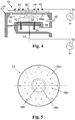
- FIG. 4 schematically shows a typical plasma reactor 40, as used for dry etching and coating processes for single wafer 42.
- the reactor 40 has a housing 43 which encloses a plasma reactor chamber 41.
- the upper end of the housing 43 is formed by a dielectric window 44, which is designed substantially as a round plate with a diameter of 520 mm and a plate thickness of 40 mm. From its upper side is an upper, coil-shaped electrode 45.
- Dielectric window 44 has a central bore for receiving an injector 46 into which one or more gas supply lines for process gases flow.
- Process gas is fed into a gastight gas distribution chamber 49 via the injector.
- This is formed by the dielectric window 44 and a mounted on the underside gas distribution plate 47 (showerhead) made of quartz glass.
- the top of the gas distributor plate 47 has a peripheral raised edge, which rests tightly against the dielectric window and closes off the gas distributor chamber 49.
- the gas distribution plate 47 is located above the wafer 42 to be treated within the plasma reactor chamber 41 and is provided with a plurality of gas nozzles 48a, 48b, 48c and 48d (see FIGS FIG. 5 ), which extend as through holes between the gas distribution chamber 49 and the underside of the gas distribution plate 47.
- the gas nozzles 48a, 48b, 48c and 48d are arranged in groups on concentric circles about the central axis 57, the gas nozzle groups differing from each other in their size, shape and / or orientation. They are suitable for generating gas flows of different strength and direction, as indicated by the directional arrows 56.
- the gas nozzles 48c have, for example, an inner diameter of 0.8 mm and they form a gas nozzle density of more than 100 gas nozzles per 100 cm 2 .
- the reactor chamber 41 is evacuatable via a gas outlet 50 connected to a high vacuum pump (not shown).
- a high vacuum pump (not shown).
- energy can be capacitively coupled into a plasma 52 ignited within the reactor chamber 41.
- Another RF power source 53 is connected to a lower electrode 54 which is below the wafer 42 to be processed is positioned.
- the wafer 42 is fixed on a holding device and surrounded by an etching ring 55 for the homogenization of the plasma action.
- the plan view of the underside of the gas distribution plate 47 in FIG. 5 shows the circular shape of the quartz glass plate. It is flat, except for a recess on the top, the gas distribution chamber 49 ( FIG. 4 ). Its diameter is 450 mm and the plate thickness 7 mm.
- the gas nozzles 48a, 48b, 48c, 48d are arranged. The arranged on the same annulus gas nozzles are the same; however, they differ in size, shape or orientation from the gas nozzles on another annulus.
- the gas distributor plate 47 thus produced is characterized by high precision. Compared to the known methods, no or low voltages are introduced into the workpiece by generating the gas nozzles in the laser etching process, which can lead to cracks in the long run. Therefore, a tempering, which can also lead to plastic deformation or change the fictitious temperature can be dispensed with.
- the bore edge becomes so hot that it melts and forms a bead over the plate surface.
- the surfaces of the quartz glass plate must be subsequently straightened or leveled, for example by grinding and polishing.
- grinding and polishing residues can get into the holes.
- a simple pre-polishing of the quartz glass plate is sufficient. Because when creating the openings by the laser etching method eliminates the need for subsequent grinding or polishing.
Priority Applications (1)
| Application Number | Priority Date | Filing Date | Title |
|---|---|---|---|
| EP17154977.7A EP3357879A1 (fr) | 2017-02-07 | 2017-02-07 | Élément de distribution de gaz destiné à être utilisé dans la fabrication de semi-conducteur et procédé de fabrication d'un élément de distribution de gaz |
Applications Claiming Priority (1)
| Application Number | Priority Date | Filing Date | Title |
|---|---|---|---|
| EP17154977.7A EP3357879A1 (fr) | 2017-02-07 | 2017-02-07 | Élément de distribution de gaz destiné à être utilisé dans la fabrication de semi-conducteur et procédé de fabrication d'un élément de distribution de gaz |
Publications (1)
| Publication Number | Publication Date |
|---|---|
| EP3357879A1 true EP3357879A1 (fr) | 2018-08-08 |
Family
ID=58108425
Family Applications (1)
| Application Number | Title | Priority Date | Filing Date |
|---|---|---|---|
| EP17154977.7A Withdrawn EP3357879A1 (fr) | 2017-02-07 | 2017-02-07 | Élément de distribution de gaz destiné à être utilisé dans la fabrication de semi-conducteur et procédé de fabrication d'un élément de distribution de gaz |
Country Status (1)
| Country | Link |
|---|---|
| EP (1) | EP3357879A1 (fr) |
Cited By (1)
| Publication number | Priority date | Publication date | Assignee | Title |
|---|---|---|---|---|
| CN113302333A (zh) * | 2018-11-28 | 2021-08-24 | 艾克斯特朗欧洲公司 | 用于制造cvd反应器的组件的方法 |
Citations (6)
| Publication number | Priority date | Publication date | Assignee | Title |
|---|---|---|---|---|
| WO2003004287A1 (fr) * | 2001-07-06 | 2003-01-16 | Corning Incorporated | Procede de formation d'un trou de reception de fibre optique |
| US20030209323A1 (en) * | 2002-05-07 | 2003-11-13 | Nec Electronics Corporation | Production apparatus for manufacturing semiconductor device |
| EP0844314B1 (fr) | 1996-11-26 | 2004-02-11 | Siemens Aktiengesellschaft | Chambre de Réaction avec un plaque de distribution des gaz |
| EP1990125A1 (fr) * | 2006-02-22 | 2008-11-12 | Nippon Sheet Glass Company Limited | Procédé de traitement de verre utilisant un laser et dispositif de traitement |
| EP2762264A1 (fr) * | 2011-11-04 | 2014-08-06 | Fujikura Ltd. | Procédé de fabrication de substrat doté de micropores |
| US9017763B2 (en) | 2012-12-14 | 2015-04-28 | Taiwan Semiconductor Manufacturing Company, Ltd. | Injector for forming films respectively on a stack of wafers |
-
2017
- 2017-02-07 EP EP17154977.7A patent/EP3357879A1/fr not_active Withdrawn
Patent Citations (6)
| Publication number | Priority date | Publication date | Assignee | Title |
|---|---|---|---|---|
| EP0844314B1 (fr) | 1996-11-26 | 2004-02-11 | Siemens Aktiengesellschaft | Chambre de Réaction avec un plaque de distribution des gaz |
| WO2003004287A1 (fr) * | 2001-07-06 | 2003-01-16 | Corning Incorporated | Procede de formation d'un trou de reception de fibre optique |
| US20030209323A1 (en) * | 2002-05-07 | 2003-11-13 | Nec Electronics Corporation | Production apparatus for manufacturing semiconductor device |
| EP1990125A1 (fr) * | 2006-02-22 | 2008-11-12 | Nippon Sheet Glass Company Limited | Procédé de traitement de verre utilisant un laser et dispositif de traitement |
| EP2762264A1 (fr) * | 2011-11-04 | 2014-08-06 | Fujikura Ltd. | Procédé de fabrication de substrat doté de micropores |
| US9017763B2 (en) | 2012-12-14 | 2015-04-28 | Taiwan Semiconductor Manufacturing Company, Ltd. | Injector for forming films respectively on a stack of wafers |
Non-Patent Citations (2)
| Title |
|---|
| KONDO Y ET AL: "THREE-DIMENSIONAL MICRODRILLING OF GLAS BY MULTIPHOTON PROCESS AND CHEMICAL ETCHING", IEE PROCEEDINGS: CIRCUITS DEVICES AND SYSTEMS, INSTITUTION OF ELECTRICAL ENGINEERS, STENVENAGE, GB, vol. 146, no. 1, 1 February 1999 (1999-02-01), pages L1146 - L1148, XP000891133, ISSN: 1350-2409 * |
| MARCINKEVICIUS A ET AL: "FEMTOSECOND LASER-ASSISTED THREE-DIMENSIONAL MICROFABRICATION IN SILICA", OPTICS LETTERS, OPTICAL SOCIETY OF AMERICA, vol. 26, no. 5, 1 March 2001 (2001-03-01), pages 277 - 279, XP001019552, ISSN: 0146-9592 * |
Cited By (2)
| Publication number | Priority date | Publication date | Assignee | Title |
|---|---|---|---|---|
| CN113302333A (zh) * | 2018-11-28 | 2021-08-24 | 艾克斯特朗欧洲公司 | 用于制造cvd反应器的组件的方法 |
| US20220033965A1 (en) * | 2018-11-28 | 2022-02-03 | Aixtron Se | Method for producing a component part of a cvd reactor |
Similar Documents
| Publication | Publication Date | Title |
|---|---|---|
| EP3592500B1 (fr) | Procédé de fabrication d'un recouvrement dans un matériau au moyen d'un rayonnement électromagnétique et avec une attaque de gravure ultérieure | |
| DE102018100299A1 (de) | Strukturiertes plattenförmiges Glaselement und Verfahren zu dessen Herstellung | |
| DE69629704T2 (de) | Verfahren und vorrichtung zum zerbrechen von sprödem material | |
| DE2821883C2 (de) | Vorrichtung zur Materialbearbeitung | |
| DE2945177C2 (fr) | ||
| DE102018110211A1 (de) | Verfahren zum Erzeugen feiner Strukturen im Volumen eines Substrates aus sprödharten Material | |
| EP3195706B1 (fr) | Procédé d'insertion d'au moins un évidement ou trou débouchant dans une pièce en forme de plaque | |
| WO2019158488A1 (fr) | Procédé et dispositif pour insérer une ligne de séparation dans un matériau transparent cassant, ainsi qu'élément pourvu d'une ligne de séparation, pouvant être fabriqué selon le procédé | |
| DE102019002761A1 (de) | Systeme zum halbleiter-wafer-dünnen und verwandte verfahren | |
| WO2021219782A1 (fr) | Tranche d'espacement utilisée pour produire un composant de transducteur électro-optique, espaceur, procédé de production de ladite tranche d'espacement, et composant de transducteur électro-optique comprenant ledit espaceur | |
| EP4013716A1 (fr) | Procédé pour usiner une pièce | |
| DE112009003752T5 (de) | Laserbearbeitungsvorrichtung, Laserbearbeitungsverfahren und Herstellungsverfahren einer Fotovoltaikvorrichtung | |
| EP3357879A1 (fr) | Élément de distribution de gaz destiné à être utilisé dans la fabrication de semi-conducteur et procédé de fabrication d'un élément de distribution de gaz | |
| EP3153838A1 (fr) | Procede de preparation d'un echantillon pour le diagnostic de microstructure et echantillon pour le diagnostic de microstructure | |
| DE19535666A1 (de) | Verfahren zur Erzeugung einer Feinkeramikstruktur | |
| DE102012217766B4 (de) | Verfahren und Vorrichtung zum Dampfdruck-Abtragschneiden eines metallischen Werkstücks | |
| CH665307A5 (de) | Vorrichtung zum beruehrungslosen erzeugen eines oertlichen vakuums auf einem werkstueck. | |
| WO2021191218A1 (fr) | Procédé, système et pièce avec enlèvement d'un gros volume de matière de la pièce par gravure assistée par laser | |
| DE102009059015B4 (de) | Quarzglasbauteil mit opaker Innenzone sowie Verfahren zur Herstellung desselben | |
| DE102019131635A1 (de) | Herstellungsvorrichtung zum additiven herstellen und verfahren zum additiven herstellen | |
| WO2012159963A1 (fr) | Procédé d'homogénéisation d'un profil de faisceau laser dans des processus comprenant l'utilisation d'un laser guidé par jet de liquide et dispositif correspondant | |
| DE102017130797B4 (de) | Verfahren zur Erzeugung eines gewünschten Oberflächenprofils | |
| WO2022148682A1 (fr) | Procédé de réduction de structures en relief sur des éléments en verre, et élément en verre produit selon le procédé | |
| EP4099427A2 (fr) | Procédé de fabrication d'une électrode de batterie | |
| EP4229016A1 (fr) | Élément de verre à paroi structurée et procédé pour le fabriquer |
Legal Events
| Date | Code | Title | Description |
|---|---|---|---|
| PUAI | Public reference made under article 153(3) epc to a published international application that has entered the european phase |
Free format text: ORIGINAL CODE: 0009012 |
|
| 17P | Request for examination filed |
Effective date: 20170314 |
|
| AK | Designated contracting states |
Kind code of ref document: A1 Designated state(s): AL AT BE BG CH CY CZ DE DK EE ES FI FR GB GR HR HU IE IS IT LI LT LU LV MC MK MT NL NO PL PT RO RS SE SI SK SM TR |
|
| AX | Request for extension of the european patent |
Extension state: BA ME |
|
| STAA | Information on the status of an ep patent application or granted ep patent |
Free format text: STATUS: THE APPLICATION IS DEEMED TO BE WITHDRAWN |
|
| 18D | Application deemed to be withdrawn |
Effective date: 20190209 |