EP3357868B1 - Water softening device and method to operate a water softening device - Google Patents
Water softening device and method to operate a water softening device Download PDFInfo
- Publication number
- EP3357868B1 EP3357868B1 EP17155008.0A EP17155008A EP3357868B1 EP 3357868 B1 EP3357868 B1 EP 3357868B1 EP 17155008 A EP17155008 A EP 17155008A EP 3357868 B1 EP3357868 B1 EP 3357868B1
- Authority
- EP
- European Patent Office
- Prior art keywords
- stream
- ratio
- filter
- base unit
- sensor
- Prior art date
- Legal status (The legal status is an assumption and is not a legal conclusion. Google has not performed a legal analysis and makes no representation as to the accuracy of the status listed.)
- Active
Links
Images


Classifications
-
- B—PERFORMING OPERATIONS; TRANSPORTING
- B01—PHYSICAL OR CHEMICAL PROCESSES OR APPARATUS IN GENERAL
- B01J—CHEMICAL OR PHYSICAL PROCESSES, e.g. CATALYSIS OR COLLOID CHEMISTRY; THEIR RELEVANT APPARATUS
- B01J39/00—Cation exchange; Use of material as cation exchangers; Treatment of material for improving the cation exchange properties
- B01J39/04—Processes using organic exchangers
- B01J39/07—Processes using organic exchangers in the weakly acidic form
-
- B—PERFORMING OPERATIONS; TRANSPORTING
- B01—PHYSICAL OR CHEMICAL PROCESSES OR APPARATUS IN GENERAL
- B01J—CHEMICAL OR PHYSICAL PROCESSES, e.g. CATALYSIS OR COLLOID CHEMISTRY; THEIR RELEVANT APPARATUS
- B01J39/00—Cation exchange; Use of material as cation exchangers; Treatment of material for improving the cation exchange properties
- B01J39/08—Use of material as cation exchangers; Treatment of material for improving the cation exchange properties
- B01J39/16—Organic material
- B01J39/18—Macromolecular compounds
-
- B—PERFORMING OPERATIONS; TRANSPORTING
- B01—PHYSICAL OR CHEMICAL PROCESSES OR APPARATUS IN GENERAL
- B01J—CHEMICAL OR PHYSICAL PROCESSES, e.g. CATALYSIS OR COLLOID CHEMISTRY; THEIR RELEVANT APPARATUS
- B01J47/00—Ion-exchange processes in general; Apparatus therefor
- B01J47/02—Column or bed processes
- B01J47/022—Column or bed processes characterised by the construction of the column or container
- B01J47/024—Column or bed processes characterised by the construction of the column or container where the ion-exchangers are in a removable cartridge
-
- B—PERFORMING OPERATIONS; TRANSPORTING
- B01—PHYSICAL OR CHEMICAL PROCESSES OR APPARATUS IN GENERAL
- B01J—CHEMICAL OR PHYSICAL PROCESSES, e.g. CATALYSIS OR COLLOID CHEMISTRY; THEIR RELEVANT APPARATUS
- B01J47/00—Ion-exchange processes in general; Apparatus therefor
- B01J47/14—Controlling or regulating
-
- B—PERFORMING OPERATIONS; TRANSPORTING
- B01—PHYSICAL OR CHEMICAL PROCESSES OR APPARATUS IN GENERAL
- B01J—CHEMICAL OR PHYSICAL PROCESSES, e.g. CATALYSIS OR COLLOID CHEMISTRY; THEIR RELEVANT APPARATUS
- B01J49/00—Regeneration or reactivation of ion-exchangers; Apparatus therefor
- B01J49/75—Regeneration or reactivation of ion-exchangers; Apparatus therefor of water softeners
-
- B—PERFORMING OPERATIONS; TRANSPORTING
- B01—PHYSICAL OR CHEMICAL PROCESSES OR APPARATUS IN GENERAL
- B01J—CHEMICAL OR PHYSICAL PROCESSES, e.g. CATALYSIS OR COLLOID CHEMISTRY; THEIR RELEVANT APPARATUS
- B01J49/00—Regeneration or reactivation of ion-exchangers; Apparatus therefor
- B01J49/80—Automatic regeneration
- B01J49/85—Controlling or regulating devices therefor
-
- C—CHEMISTRY; METALLURGY
- C02—TREATMENT OF WATER, WASTE WATER, SEWAGE, OR SLUDGE
- C02F—TREATMENT OF WATER, WASTE WATER, SEWAGE, OR SLUDGE
- C02F1/00—Treatment of water, waste water, or sewage
-
- C—CHEMISTRY; METALLURGY
- C02—TREATMENT OF WATER, WASTE WATER, SEWAGE, OR SLUDGE
- C02F—TREATMENT OF WATER, WASTE WATER, SEWAGE, OR SLUDGE
- C02F1/00—Treatment of water, waste water, or sewage
- C02F1/008—Control or steering systems not provided for elsewhere in subclass C02F
-
- C—CHEMISTRY; METALLURGY
- C02—TREATMENT OF WATER, WASTE WATER, SEWAGE, OR SLUDGE
- C02F—TREATMENT OF WATER, WASTE WATER, SEWAGE, OR SLUDGE
- C02F1/00—Treatment of water, waste water, or sewage
- C02F1/42—Treatment of water, waste water, or sewage by ion-exchange
-
- C—CHEMISTRY; METALLURGY
- C02—TREATMENT OF WATER, WASTE WATER, SEWAGE, OR SLUDGE
- C02F—TREATMENT OF WATER, WASTE WATER, SEWAGE, OR SLUDGE
- C02F1/00—Treatment of water, waste water, or sewage
- C02F1/42—Treatment of water, waste water, or sewage by ion-exchange
- C02F2001/425—Treatment of water, waste water, or sewage by ion-exchange using cation exchangers
-
- C—CHEMISTRY; METALLURGY
- C02—TREATMENT OF WATER, WASTE WATER, SEWAGE, OR SLUDGE
- C02F—TREATMENT OF WATER, WASTE WATER, SEWAGE, OR SLUDGE
- C02F2201/00—Apparatus for treatment of water, waste water or sewage
- C02F2201/002—Construction details of the apparatus
- C02F2201/006—Cartridges
-
- C—CHEMISTRY; METALLURGY
- C02—TREATMENT OF WATER, WASTE WATER, SEWAGE, OR SLUDGE
- C02F—TREATMENT OF WATER, WASTE WATER, SEWAGE, OR SLUDGE
- C02F2201/00—Apparatus for treatment of water, waste water or sewage
- C02F2201/002—Construction details of the apparatus
- C02F2201/007—Modular design
-
- C—CHEMISTRY; METALLURGY
- C02—TREATMENT OF WATER, WASTE WATER, SEWAGE, OR SLUDGE
- C02F—TREATMENT OF WATER, WASTE WATER, SEWAGE, OR SLUDGE
- C02F2209/00—Controlling or monitoring parameters in water treatment
- C02F2209/05—Conductivity or salinity
-
- C—CHEMISTRY; METALLURGY
- C02—TREATMENT OF WATER, WASTE WATER, SEWAGE, OR SLUDGE
- C02F—TREATMENT OF WATER, WASTE WATER, SEWAGE, OR SLUDGE
- C02F2209/00—Controlling or monitoring parameters in water treatment
- C02F2209/44—Time
- C02F2209/445—Filter life
-
- C—CHEMISTRY; METALLURGY
- C02—TREATMENT OF WATER, WASTE WATER, SEWAGE, OR SLUDGE
- C02F—TREATMENT OF WATER, WASTE WATER, SEWAGE, OR SLUDGE
- C02F2301/00—General aspects of water treatment
- C02F2301/04—Flow arrangements
- C02F2301/043—Treatment of partial or bypass streams
-
- C—CHEMISTRY; METALLURGY
- C02—TREATMENT OF WATER, WASTE WATER, SEWAGE, OR SLUDGE
- C02F—TREATMENT OF WATER, WASTE WATER, SEWAGE, OR SLUDGE
- C02F2303/00—Specific treatment goals
- C02F2303/22—Eliminating or preventing deposits, scale removal, scale prevention
Definitions
- the present invention refers to a water softening device and to a method to operate a water softening device.
- Water softening methods are well known and typically involve a pressurized water treatment wherein a water stream is passed through a filter comprising a cation exchange material (either inorganic or organic), thereby producing a softened water which is desirable for household applications like laundering, bathing and dish washing, devices like coffee machines, in particular those with steam production, as well as many industrial applications.
- a cation exchange material either inorganic or organic
- the main purpose of water softening is to protect devices from lime scale. This is accomplished by exchanging calcium and magnesium ions (the so-called hardness) in a water stream for example for sodium or potassium ions.
- Each cation exchange material has a defined capacity corresponding to the amount of cations that can be exchanged against hardness.
- the volume of water that can be treated by the filter before the filter is exhausted and needs to be replaced depends on the composition of the treated water. For obvious reasons it is advantageous to have an indicator for the exhaustion state of the filter.
- the criteria used to determine the exhaustion state of a filter is the pH value of a water stream after treatment by the filter comprising the cation exchange material. Usually below a pH value of 6.8 the protection against lime scale is ensured. When the exhaustion rate of the filter has progressed to a point at which the pH exceeds a value of 6.8, the filter needs to be replaced.
- the direct determination of the pH value of the water stream after treatment is not an optimum choice to determine the exhaustion state.
- the price of pH measurements is one aspect.
- the fact that a pH sensor would need frequent calibrations is another aspect.
- the optimum solution should be cost efficient and autonomous.
- a first sensor is placed before the filter and measures the electrical conductivity of raw water.
- the filter is operated in Na + -Mode.
- a second sensor is positioned downstream of the filter and measures the electrical conductivity of water which has passed the filter. From the measured conductivities, hardness of the raw water and the filtered water is determined. When the determined hardness of the filtered water exceeds a threshold value, a regeneration or exchange of the filter is indicated.
- the publication EP 3034474A1 discloses a water softening system with a first bed of liquid treatment medium including cation exchange resin operated in H+ mode that can also be buffered with a potassium salt or a sodium salt. This document also discloses determining electrical conductivity of the softened water with a conductivity sensor in order to determine the reduction in carbonate hardness and thus the amount of free CO2 generated.
- the present invention is based on the object to provide a technical solution to the described problem of indicating the exhaustion state of a filter for a water softening process.
- the present invention is based on the understanding that the result of measurements of electrical properties of the water which is passed through a filter comprising a cation exchange material may serve as an indicator for the exhaustion state of the filter.
- measurements of the electrical conductivity are advantageous.
- the cost of sensors for the measurements of electrical properties, including the electronics needed to operate them, is considerably lower than for the equipment needed for pH measurements.
- sensors for the measurements of electrical properties usually do require only a one time calibration.
- a water softening device comprises
- the water softening device may further comprise a third sensor for detecting a water flow through the filter.
- this feature is optional.
- the device comprises an electronic control unit which is connected to the first sensor, to the second sensor and optionally, if the device comprises the third sensor, to the third sensor, and which comprises an internal data memory and a data processing unit.
- the device is configured to determine a ratio between the measured electrical conductivity and/or of the second stream and the measured electrical conductivity and/or resistance of the first stream and use the ratio as an indicator for the exhaustion state of the filter.
- the device has a modular design.
- the base unit can comprise all components which do not exhaust during operation.
- the filter may comprise only a cation exchange material that is subject to exhaustion during operation of the device. When exhaustion occurs, the filter can be replaced. In contrast to this, the base unit is reusable.
- a screw connection can provide a very reliable and leakproof connection between the base unit and the filter.
- the filter comprises an opening part with an external thread
- the base unit comprises a receptacle for the filter with an internal thread, wherein form and dimensions of the threads are matched to one another.
- the opening provides access to the filter's inlet for the first stream and the outlet for the second stream.
- the receptacle comprises an entry into the base unit's outlet line.
- the base unit's inlet line opens into the receptacle.
- the opening and the receptacle are interrelated and adjusted to one another such that the inlet line of the base unit is coupled to the inlet of the filter and the outlet line of the base unit is coupled to the outlet of the filter when the opening part with the external thread is screwed into the receptacle.
- one or more sealing compounds are arranged at the interface between the filter and the base unit.
- the first sensor and the second sensor are configured to measure an electrical conductivity.
- Sensors suitable for measuring the electrical conductivity of water in particular electrolytic cells suitable for measuring the electrical conductivity of water, are known to persons skilled in the art and need no further explanation.
- Such water treated over a WAC resin bed operated under H+ form would react as follow: 2 R-COO-H + Ca 2+ + 2 HCO 3 - ⁇ (R-COO) 2 -Ca + 2 H 2 CO 3
- the device 100 shown in Fig. 2 comprises an inlet line 101 for a first stream of raw water. At the junction 102 the first stream of raw water is split into two partial streams. One of the partial streams is led via line 104 to the filter 105. The other partial stream flows through the bypass line 103. The ratio between the two partial streams is regulated by means of the valve 112.
- the device 100 comprises two sensors 109 and 110 for measuring electrical conductivity of the water flowing through the device.
- Sensor 109 is positioned at the inlet line 101.
- Sensor 110 is positioned at the outlet line 107.
- device 100 comprises sensor 108 for detecting a water flow through the filter 105.
- the sensor 108 gives information about the presence of a water flow through the filter 105.
- the sensors 108 to 110 are connected to the electronic control unit 111.
- the sensors 109 and 110 it is possible to determine a ratio between the electrical conductivity of softened water which has at least partially been treated in the filter 105 and the electrical conductivity of the raw water. After each exchange of the filter 105 a certain time is needed to stabilize the conductivity measurements. Then the ratio is determined. It has been found (see below) that by monitoring this ratio it is possible to identify a conductivity ratio value that corresponds to a certain pH value. Usually a filter containing a WAC resin should be replaced when the pH value of the treated water reaches 6.8.
- the conductivity ratio will decrease to reach a minimum, if the filter 105 contains a buffered WAC resin. After this minimum the conductivity ratio will start to increase until the end of the filter's 105 lifetime.
- Fig. 1 The operation principle of a WAC resin bed operated under H+ form was illustrated by Fig. 1 .
- the ion exchange resin can be buffered with an additional salt that could be any ion that would have a lower selectivity than the ions to be exchanged.
- K + , Na + and/or Li + are preferred.
- an ion exchange resin buffered with Na + is used.
- the sodium quantity for this application could be located in the range from 0.1 mol to 1.0 mol of sodium per liter of ion exchange resin.
- the ion exchange resin shows different selectivities for the different ions present in the solution.
- selectivity is usually as follows: K + ⁇ Na + ⁇ Li + ⁇ Mg 2+ ⁇ Ca 2+ ⁇ H +
- the WAC resin will exchange mostly the buffering ion (ex: Na + ) against Ca 2+ and Mg 2+ but also H + as described above.
- the quantity of buffering ion (ex: Na + ) exchanged against Ca 2+ and Mg 2+ will decrease, while the amount of H + will increase.
- This will lead to a decrease of the pH at the beginning of the cycle, limited by the buffer ion release.
- the HCO 3 - concentration will also decrease.
- the hardness leakage will start to increase accordingly.
- Fig. 3 illustrates the change of concentration of the ion species Ca 2+ , Na + and HCO 3 - in the water stream passed through the filter.
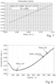
- Fig. 4 illustrates the change of pH of the water passed through the filter.
- Fig. 5 illustrates the change of the ratio of the electrical conductivity of the water passed through the filter and the electrical conductivity of the raw water.
- the volume corresponding to a pH of 6.8 is about 750 liters.
- the ratio corresponding to a volume of 750 liters is about 0,85. Combining this information leads to the conclusion that a pH of 6.8 corresponds to a ratio of 0,85. This is why this ratio is named ratio_6.8. Further, it is possible to extract from the curve in Fig. 5 the lowest ratio, ratio_min, which has a value of 0.64 in this case.
- ratio_min there is a direct link between the ratio_min and the ratio_6.8.
- a filter was tested for different water compositions (ratio TH / Alk.).
- the filter used for the tests had a fixed given amount of WAC ion exchange resin.
- the resin was always conditioned in the same way, using Na + as buffer with always the same quantity located between 0.1 and 1.0 mol of Na + per liter of resin.
- the bypass was adjusted from 10 to 70 % according to the water alkalinity.
- ratio_min and ratio_6.8 were linear as a function of the ratio TH /Alk.
- Ratio_min and ratio_6.8 depend on the WAC ion exchange resin used, its capacity and the amount of buffer loaded (here Na + ), as well as on the raw water composition, especially the ratio TH / Alk.
- the ratio_6.8 corresponding to the exhaustion point is linear to the ratio_min.
- This curve is characteristic for a defined filter type and can be used as exhaustion criteria.
- a device can be configured to determine a warning ratio (ratio_warning) to give information to a user of the device that the filter is coming to the end of its lifetime and will need to be replaced soon.
- the device according to the invention comprises three LEDs (green, orange and red) as optical signaling devices.
- the lightning of the LEDs is controlled as follows: • Green ON: ratio_actual ⁇ ratio_warning • Orange ON: ratio_warning ⁇ ratio_actual ⁇ ratio_6.8 • Red ON: ratio_actual > ratio_6.8
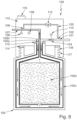
- the device 100 shown in Fig. 9 comprises a base unit 115 and an exchangeable filter 105.
- the base unit 115 and the filter 105 are connected via a screw connection.
- the filter comprises an external thread 117 and the base unit comprises an internal thread 118.
- the sealing rings 113 and 114 are arranged at an interface between the filter 105 and the base unit 115.
- the base unit comprises an inlet line 101 for a first stream of raw water, an outlet line 107 for a second stream of water with decreased hardness exiting from the filter 105 and a bypass line 103.
- the first stream of raw water is split into two partial streams.
- One of the partial streams is led via line 104 to the filter 105.
- the other partial stream flows through the bypass line 103.
- the ratio between the two partial streams can be regulated by means of the valve 112.
- water which has exited from the filter 105 can be blended with raw water from the bypass line 103.
- Via the outlet line 107 the water can exit from the device 100. Arrows are used to illustrate the directions in which the water streams flow within the device.
- the filter 105 comprises an inlet 105a for the first stream of raw water and an outlet 105b for the second stream of water with decreased hardness.
- the inlet line 101 of the base unit 115 is coupled to the inlet 105a of the filter 105 and the outlet line 107 of the base unit 115 is coupled to the outlet 105b of the filter 105.
- the filter 105 contains a WAC resin 105d operated under H + form and buffered with Na + .
- the WAC resin 105d is contained in a cartridge 105c.
- Na + ions and H + ions fixed on the WAC resin 105d are exchanged against hardness. Initially primarily Na + ions are exchanged. Later, the output of H + ions increases and the output of Na + ions decreases.
- the device 100 comprises two sensors 109 and 110 for measuring electrical conductivity of the water flowing through the device.
- Sensor 109 is positioned at the outlet line 107.
- Sensor 110 is positioned at the inlet line 101.
- device 100 comprises sensor 108 for detecting a water flow through the filter 105.
- the sensor 108 gives information about the presence of a water flow through the filter 105.
- the sensors 108 to 110 are connected to an electronic control unit 111, as shown in Fig. 2 .
- the electronic control unit is not visible in the cross-section showed in Fig. 9 .
- the device 100 further comprises 3 LEDs 116 as a filter replacement indicator. With the help of the LEDs 116 it is possible to give a first warning prior to the filter exhaustion in order to inform the user that the filter is at the end of its lifetime and a second warning when the filter is exhausted, as already described above.
Landscapes
- Chemical & Material Sciences (AREA)
- Organic Chemistry (AREA)
- Chemical Kinetics & Catalysis (AREA)
- Life Sciences & Earth Sciences (AREA)
- Hydrology & Water Resources (AREA)
- Engineering & Computer Science (AREA)
- Environmental & Geological Engineering (AREA)
- Water Supply & Treatment (AREA)
- Treatment Of Water By Ion Exchange (AREA)
Description
- The present invention refers to a water softening device and to a method to operate a water softening device.
- Water softening methods are well known and typically involve a pressurized water treatment wherein a water stream is passed through a filter comprising a cation exchange material (either inorganic or organic), thereby producing a softened water which is desirable for household applications like laundering, bathing and dish washing, devices like coffee machines, in particular those with steam production, as well as many industrial applications.
- The main purpose of water softening is to protect devices from lime scale. This is accomplished by exchanging calcium and magnesium ions (the so-called hardness) in a water stream for example for sodium or potassium ions.
- Other filters containing a weak acid cationic ion exchange resin (WAC) as cation exchange material. Such filters exchange the hardness against protons. This means that water softening is accompanied by a drop of pH of the treated water.
- Each cation exchange material has a defined capacity corresponding to the amount of cations that can be exchanged against hardness. The volume of water that can be treated by the filter before the filter is exhausted and needs to be replaced depends on the composition of the treated water. For obvious reasons it is advantageous to have an indicator for the exhaustion state of the filter.
- Classically the criteria used to determine the exhaustion state of a filter is the pH value of a water stream after treatment by the filter comprising the cation exchange material. Usually below a pH value of 6.8 the protection against lime scale is ensured. When the exhaustion rate of the filter has progressed to a point at which the pH exceeds a value of 6.8, the filter needs to be replaced.
- For several reasons the direct determination of the pH value of the water stream after treatment is not an optimum choice to determine the exhaustion state. The price of pH measurements is one aspect. The fact that a pH sensor would need frequent calibrations is another aspect. The optimum solution should be cost efficient and autonomous.
- Another method to determine the exhaustion state of a filter can be found in the publications
EP 2481713 A1 andDE 102010003636 A1 . - In
EP 2481713 A1 a first sensor is placed before the filter and measures the electrical conductivity of raw water. The filter is operated in Na+-Mode. A second sensor is positioned downstream of the filter and measures the electrical conductivity of water which has passed the filter. From the measured conductivities, hardness of the raw water and the filtered water is determined. When the determined hardness of the filtered water exceeds a threshold value, a regeneration or exchange of the filter is indicated. - In analogy to
EP 2481713 A1 inDE 102010003636 A1 electrical conductivity measurements are used to determined hardness of a raw water and filtered water. Water hardness is derived from the measured electrical conductivity using a conversion factor. Exhaustion of the filter is indicated when the specific hardness of the softened water exceeds a threshold value. - The publication
EP 3034474A1 discloses a water softening system with a first bed of liquid treatment medium including cation exchange resin operated in H+ mode that can also be buffered with a potassium salt or a sodium salt. This document also discloses determining electrical conductivity of the softened water with a conductivity sensor in order to determine the reduction in carbonate hardness and thus the amount of free CO2 generated. - The present invention is based on the object to provide a technical solution to the described problem of indicating the exhaustion state of a filter for a water softening process.
- This object is achieved by the water softening device having the features of
claim 1 and by the method to operate a water softening device having the features of claim 10. Preferred embodiments of the device are specified independent Claims 2 to 9. Preferred embodiments of the method is specified in dependent claims 11 to 14. - The present invention is based on the understanding that the result of measurements of electrical properties of the water which is passed through a filter comprising a cation exchange material may serve as an indicator for the exhaustion state of the filter. In comparison to the direct determination of pH values measurements of the electrical conductivity are advantageous. The cost of sensors for the measurements of electrical properties, including the electronics needed to operate them, is considerably lower than for the equipment needed for pH measurements. In addition, sensors for the measurements of electrical properties usually do require only a one time calibration.
- A water softening device according to the invention comprises
- a filter which is configured to decrease hardness of a first stream of raw water to produce a second stream of water with decreased hardness,
- a first sensor configured to measure an electrical conductivity and/or an electrical resistance of the first stream, and
- a second sensor configured to measure an electrical conductivity and/or an electrical resistance of the second stream,
- the filter comprises an ion exchange resin operated in H+-mode, and
- the ion exchange resin is buffered, and
- the ion exchange resin is buffered with at least one salt selected from the group of a potassium salt (K+), a sodium salt (Na+) and a lithium salt (Li+).
- The water softening device may further comprise a third sensor for detecting a water flow through the filter. However, this feature is optional.
- The device comprises an electronic control unit which is connected to the first sensor, to the second sensor and optionally, if the device comprises the third sensor, to the third sensor, and which comprises an internal data memory and a data processing unit.
- Further, the device is configured to determine a ratio between the measured electrical conductivity and/or of the second stream and the measured electrical conductivity and/or resistance of the first stream and use the ratio as an indicator for the exhaustion state of the filter.
- In preferred embodiments the water softening device comprises at least one of the following additional features:
- The device comprises a base unit.
- The first sensor, the second sensor and optionally, if the device comprises the third sensor also the third sensor, are integral parts of the base unit.
- The filter is configured as exchangeable filter which is detachably connectable to the base unit.
- Thus, it is preferred that the device has a modular design. The base unit can comprise all components which do not exhaust during operation. The filter may comprise only a cation exchange material that is subject to exhaustion during operation of the device. When exhaustion occurs, the filter can be replaced. In contrast to this, the base unit is reusable.
- In further preferred embodiments the water softening device may be characterized by at least one of the following additional features:
- The base unit and the filter are connected via a screw connection.
- The filter comprises an inlet for the first stream and an outlet for the second stream.
- The base unit comprises an inlet line for the first stream and an outlet line for the second stream.
- The inlet line of the base unit is coupled to the inlet of the filter and the outlet line of the base unit is coupled to the outlet of the filter.
- A screw connection can provide a very reliable and leakproof connection between the base unit and the filter. It is preferred that the filter comprises an opening part with an external thread whereas the base unit comprises a receptacle for the filter with an internal thread, wherein form and dimensions of the threads are matched to one another. The opening provides access to the filter's inlet for the first stream and the outlet for the second stream. The receptacle comprises an entry into the base unit's outlet line. In addition, the base unit's inlet line opens into the receptacle. Preferably the opening and the receptacle are interrelated and adjusted to one another such that the inlet line of the base unit is coupled to the inlet of the filter and the outlet line of the base unit is coupled to the outlet of the filter when the opening part with the external thread is screwed into the receptacle.
- In order to provide leakproofness, it can be preferred that one or more sealing compounds, in particular one or more sealing rings, are arranged at the interface between the filter and the base unit.
- Of course, it would be also possible to connect the base unit and the filter by other technical means, for example by means of a simple snap connection.
- In further preferred embodiments the water softening device may be characterized by at least one of the following additional features:
- The first sensor is configured as an electrolytic cell capable of applying a current to the first stream.
- The second sensor is configured as an electrolytic cell capable of applying a current to the second stream.
- The first sensor is positioned within the inlet line of the base unit or at an entry of the inlet line of the base unit.
- The second sensor is positioned within the outlet line of the base unit or at an entry of the outlet line of the base unit.
- The optional third sensor is, if present, positioned within the inlet line of the base unit or at an entry of the inlet line of the base unit or within the outlet line of the base unit or at an entry of the outlet line of the base unit.
- Generally it is preferred that the first sensor and the second sensor are configured to measure an electrical conductivity. Sensors suitable for measuring the electrical conductivity of water, in particular electrolytic cells suitable for measuring the electrical conductivity of water, are known to persons skilled in the art and need no further explanation.
- In further preferred embodiments the water softening device may be characterized by the following additional feature:
- The electronic control unit is an integral part of the base unit.
- Preferably the electronic control unit and all sensors are integral parts of the base unit.
- In further preferred embodiments the water softening device may be characterized by at least one of the following additional features:
- The filter comprises a cartridge in which the ion exchange resin is contained, wherein the cartridge preferably consists of plastic.
- The ion exchange resin is a weak acid cationic ion exchange resin (WAC resin).
- It is particularly preferred that the ion exchange resin is a buffered WAC resin, in particular a WAC resin buffered with at least one salt selected from the group of a potassium salt (K+), a sodium salt (Na+) and a lithium salt (Li+). If the WAC resin is buffered, it contains - besides H+ ions - an amount of metallic cations, in particular K+, Na+ and/or Li+.
- In further preferred embodiments the water softening device may be characterized by at least one of the following additional features:
- The device comprises a bypass line for mixing the second stream with water of the first stream.
- The bypass line connects the inlet line of the base unit with the outlet line of the base unit.
- The bypass line comprises a valve to regulate the amount of water of the first stream mixed to the second stream.
- The bypass line is integrated into the base unit.
- Via the bypass line the second stream can be blended with water of the first stream. This may become useful if, for example, as a result of the treatment with the water softening device the pH of the second stream drops too far.
- In further preferred embodiments the water softening device may be characterized by at least one of the following additional features:
- The device comprises a filter replacement indicator configured to indicate that the filter has reached the end of its lifetime or is near to the end of its lifetime.
- The replacement indicator is an optical signaling device and/or a sounder.
- The filter replacement indicator is an integral part of the base unit.
- The filter replacement indicator is connected to the electronic control unit.
- The electronic control unit is configured to trigger the replacement indicator to issue a warning signal in dependence from electrical properties of the first and the second stream measured by the first and the second sensor.
- It is preferred that the device is characterized by a combination of all of these features. Such a device is not only capable to determine an exhaustion state of a filter. Moreover, it is capable to issue a warning signal to give information to the operator that the filter is coming to the end of its lifetime and will need to be replaced soon.
- In further preferred embodiments the water softening device may be characterized by at least one of the following additional features:
- The device comprises a mount for stationary installation of the base unit.
- The mount comprises one or more holes and is connected or connectable to the base unit.
- It is possible to position the base unit in a fixed, stationary position via the mount. During operation, only the filter has to be exchanged.
- The method according to the invention is a method to operate a water softening device. Preferably the device operated according to this method is a device like the one described above. It comprises the steps of
- passing a first stream of raw water through a filter which is configured to decrease hardness of the stream to produce a second stream of water with decreased hardness,
- measuring an electrical conductivity or an electrical resistance of the first stream with a first sensor,
- measuring an electrical conductivity or an electrical resistance of the second stream with a second sensor,
- determining a ratio between the measured electrical property of the second stream and the measured electrical property of the first stream and
- using the ratio as an indicator for the exhaustion state of the filter,
- the filter comprises an ion exchange resin operated in H+-mode, and
- Preferably the measuring of the electric properties of the first and the second stream is accomplished simultaneously or in a defined delay.
- In a preferred embodiment the method may be characterized by the following additional feature:
- The ratio is the ratio between the electrical conductivity of the second stream and the electrical conductivity of the first stream.
- In practice, it would also be possible to form a ratio between the electrical conductivity of the first stream and the electrical conductivity of the second stream (and not vice versa, namely between the electrical conductivity of the second stream and the electrical conductivity of the first stream). Actually in both cases a ratio is obtained which may be used as an indicator for the exhaustion state of the filter.
- In further preferred embodiments the method may be characterized by the following additional features and/or steps:
- A sequence of measurements of the electrical conductivities of the first and the second stream is conducted.
- From the results of each of the measurements the ratio between the electrical conductivity of the second stream and the electrical conductivity of the first stream is determined, thereby obtaining a sequence of ratios.
- The lowest ratio ratio_min is determined.
- A threshold value ratio_exhaust is determined as a function of ratio_min.
- The threshold value ratio_exhaust corresponds to a pH value at which the filter needs to be replaced. As initially mentioned, usually this is the case at a pH value of 6.8. Thus, in this case ratio_exhaust could also be named ratio_6.8.
- In further preferred embodiments the method may be characterized by at least one of the following additional steps:
- A threshold value ratio_exhaust is calculated according to the formula

- A threshold value ratio_exhaust is calculated according to the formula

- In further preferred embodiments the method may be characterized by at least one of the following additional features and/or steps:
- The threshold value ratio_warning is a predetermined value.
- The threshold value ratio_warning is calculated from data obtained by the measurements of the electrical properties of the first and the second stream.
- The threshold value ratio_warning is calculated from the ratio between the electrical conductivity of the second stream and the electrical conductivity of the first stream.
- The threshold value ratio_warning is determined as a function of ratio_exhaust.
- More detailed description of the invention / working example
- Further features and advantages of the invention can be derived from the figures and the following detailed description of preferred embodiments. The preferred embodiments described are merely for the purposes of illustration and to give a better understanding of the invention and shall not in any way constitute a restriction.
-
Fig. 1 illustrates the general process of ion exchange during operation of a water softening device containing a filter comprising a non-buffered WAC resin. -
Fig. 2 illustrates schematically the most important features of a preferred embodiment of a water softening device according to the invention. -
Fig. 3 illustrates the change of concentration of the ion species Ca2+, Na+ and HCO3 - in a water stream passed through a filter containing a WAC resin buffered with a sodium salt as a function of the volume passed through the filter. -
Fig. 4 illustrates the change of pH of water passed through a filter containing a WAC resin buffered with a sodium salt as a function of the volume passed through the filter. -
Fig. 5 illustrates the change of the electrical conductivity of water passed through a filter containing a WAC resin buffered with a sodium salt as a function of the volume passed through the filter. -
Fig. 6 illustrates the changes of ratio_min and of ratio_6.8 as a function of the ratio TH / Alk.. -
Fig. 7 illustrates the linear relation between the ratio_min and the ratio_6.8. -
Fig. 8 illustrates the relation between the ratio_min, ration_warning and the ratio_6.8. -
Fig. 9 a cross-section of a further preferred embodiment of a water softening device according to the invention (schematic illustration). - For most natural water encountered, the total hardness TH (TH corresponds to the sum of the concentrations of Ca2+ and Mg2+ ions in the water: TH = [Ca2+] + [Mg2+]) is higher than the alkalinity Alk. (the alkalinity is proportional to the concentration of HCO3 - ions: Alk. ~ [HCO3 -]), so that the ratio TH / Alkalinity > 1. Such water treated over a WAC resin bed operated under H+ form, would react as follow:
2 R-COO-H + Ca2+ + 2 HCO3 - → (R-COO)2-Ca + 2 H2CO3
- The H+ ions fixed on the WAC resin are exchanged against hardness (Ca2+ and Mg2+). The H+ ions given by the resin will then react with the alkalinity (HCO3 -) to be transformed into CO2 (H2CO3). In other words, the hardness will be exchanged up to the alkalinity concentration.
- The process, also known as de-alkalisation process, is quantitatively illustrated in
Fig. 1 . It is governed by the ratio of TH to Alk.. In order to avoid the pH of the treated water to drop to a too low value, it is possible, sometimes even advisable, to mix the treated water with a defined percentage of the raw water (for ex. 10 to 70 %). The bypass setting is usually a consequence of the raw water composition that governs the WAC resin reaction and the composition of the treated water. - The
device 100 shown inFig. 2 comprises aninlet line 101 for a first stream of raw water. At thejunction 102 the first stream of raw water is split into two partial streams. One of the partial streams is led vialine 104 to thefilter 105. The other partial stream flows through thebypass line 103. The ratio between the two partial streams is regulated by means of thevalve 112. - The
filter 105 contains a WAC resin bed operated under H+ form. When water flows through thefilter 105, H+ ions fixed on the WAC resin are exchanged against hardness. Atjunction 106 water which has exited from thefilter 105 can be blended with raw water from thebypass line 103. Viaoutlet line 107 the water can exit from thedevice 100. - The
device 100 comprises twosensors Sensor 109 is positioned at theinlet line 101.Sensor 110 is positioned at theoutlet line 107. In addition to this,device 100 comprisessensor 108 for detecting a water flow through thefilter 105. Thesensor 108 gives information about the presence of a water flow through thefilter 105. Thesensors 108 to 110 are connected to theelectronic control unit 111. - With the help of the
sensors filter 105 and the electrical conductivity of the raw water. After each exchange of thefilter 105 a certain time is needed to stabilize the conductivity measurements. Then the ratio is determined. It has been found (see below) that by monitoring this ratio it is possible to identify a conductivity ratio value that corresponds to a certain pH value. Usually a filter containing a WAC resin should be replaced when the pH value of the treated water reaches 6.8. - At the beginning of the filter's 105 lifetime, the conductivity ratio will decrease to reach a minimum, if the
filter 105 contains a buffered WAC resin. After this minimum the conductivity ratio will start to increase until the end of the filter's 105 lifetime. - The operation principle of a WAC resin bed operated under H+ form was illustrated by
Fig. 1 . In order to avoid the pH of the treated water to drop to a too low value especially at the beginning of the cycle, in addition to the bypass, the ion exchange resin can be buffered with an additional salt that could be any ion that would have a lower selectivity than the ions to be exchanged. Usually K+, Na+ and/or Li+ are preferred. In the present case preferably an ion exchange resin buffered with Na+ is used. The sodium quantity for this application could be located in the range from 0.1 mol to 1.0 mol of sodium per liter of ion exchange resin. - The ion exchange resin shows different selectivities for the different ions present in the solution. For a WAC resin the selectivity is usually as follows:
K+ < Na+ < Li+ < Mg2+ < Ca2+ < H+
- This means that for a WAC resin regenerated under H+ form and buffered with any additional salt with lower selectivity than the ions to be exchanged (ex: Na+ buffer for Ca2+ and Mg2+ removal), hardness would be preferentially exchanged against the buffering ion Na+, because of the resin selectivity. When the available buffering ions Na+ are exchanged, the regular de-alkalisation process occurs. The Ca2+ and Mg2+ are exchanged against H+ that will react with the alkalinity to be transformed into CO2. The buffering ion (ex: Na+) release is leading to a smoother H+ release at the beginning of the cycle that contributes avoiding the pH to drop to a lower value.
- At the beginning of the cycle, the WAC resin will exchange mostly the buffering ion (ex: Na+) against Ca2+ and Mg2+ but also H+ as described above. As far as the amount of water passed through the filter will increase, the quantity of buffering ion (ex: Na+) exchanged against Ca2+ and Mg2+ will decrease, while the amount of H+ will increase. This will lead to a decrease of the pH at the beginning of the cycle, limited by the buffer ion release. As a part of the alkalinity will be transformed into CO2, the HCO3 - concentration will also decrease. At same time, the hardness leakage will start to increase accordingly.
- Once all the loaded buffer ions have been released, an inflection of the curves occurs. The pH will start to increase until the complete exhaustion of the filter. It means at the beginning of the cycle, the pH will pass by a minimum value (ratio_min) and will then increase to reach the ratio corresponding to a pH of 6.8 (ratio_6.8 or ratio_exchange, compare above), the criteria for filter replacement.
- Experiments have been conducted with a filter containing a WAC resin buffered with Na+ from 0.1 to 1.0 mol per liter resin. A stream of raw water has been passed through the filter. The composition of the raw water at the filter inlet was analyzed:
T = 20°C pH = 7.68 Alkalinity = 4.77 meq/l Ca2+ = 4.70 meq/l Mg2+ = 0.41 meq/l Na+ = 0.17 meq/l K+ = 0.05 meq/l NO3 - = 0.25 meq/l Cl- = 0.25 meq/l SO4 2- = 0.36 meq/l - In the experiment the filter was brought to complete exhaustion. A water stream has been passed through the filter until the outlet water composition was similar to the inlet composition. The electrical conductivity of the water stream was continuously monitored at the inlet of the filter and at the outlet.
-
Fig. 3 illustrates the change of concentration of the ion species Ca2+, Na+ and HCO3 - in the water stream passed through the filter.Fig. 4 illustrates the change of pH of the water passed through the filter.Fig. 5 illustrates the change of the ratio of the electrical conductivity of the water passed through the filter and the electrical conductivity of the raw water. - From the three curves in
Figs. 3 - 5 it becomes evident that the HCO3 - concentration, the pH and the ratio of the electrical conductivities are following the same evolution. In fact the HCO3 - concentration, the pH and the ratio are linked together. In the experiment the raw water conductivity was stable. As a consequence, the ratio follows the outlet conductivity evolution. The electrical conductivity is proportional to the HCO3 - concentration which is directly linked to pH and alkalinity according to the calco-carbonic equilibrium. - According to the curve in
Fig. 4 the volume corresponding to a pH of 6.8 is about 750 liters. According to the curve inFig. 5 the ratio corresponding to a volume of 750 liters is about 0,85. Combining this information leads to the conclusion that a pH of 6.8 corresponds to a ratio of 0,85. This is why this ratio is named ratio_6.8. Further, it is possible to extract from the curve inFig. 5 the lowest ratio, ratio_min, which has a value of 0.64 in this case. - There is a direct link between the ratio_min and the ratio_6.8. To demonstrate the relation between both, a filter was tested for different water compositions (ratio TH / Alk.). The filter used for the tests had a fixed given amount of WAC ion exchange resin. The resin was always conditioned in the same way, using Na+ as buffer with always the same quantity located between 0.1 and 1.0 mol of Na+ per liter of resin. The bypass was adjusted from 10 to 70 % according to the water alkalinity.
- The results are illustrated in
Fig. 6 with the values of ratio_min and ratio_6.8 for the different water compositions, given as a function of the ratio TH / Alk. For the different water compositions tested, the ratio_min and the ratio_6.8 were linear as a function of the ratio TH /Alk.. Ratio_min and ratio_6.8 depend on the WAC ion exchange resin used, its capacity and the amount of buffer loaded (here Na+), as well as on the raw water composition, especially the ratio TH / Alk. - This means that for a given WAC resin type, the same amount a buffer loaded on the resin compared to the main regenerant H+ and the same water composition, the ratio_min and ratio_6.8 will always pass by the same values.
- The fact the ratio_min and the ratio_6.8 are both linear to the ratio TH / Alk. on the considered range leads to the conclusion that there is also a linear relation between the ratio_min and the ratio_6.8. This is illustrated by the curve shown in
Fig. 7 . - Conclusion: For a given filter size, using always the same amount of WAC ion exchange resin conditioned in the same way, the ratio_6.8 corresponding to the exhaustion point is linear to the ratio_min. This curve is characteristic for a defined filter type and can be used as exhaustion criteria. In the present case the exhaustion criteria is:

- So, once the ratio_min is known, it is possible to calculate the value for the ratio_6.8 from this equation, which corresponds to the point the filter will need to be replaced. The exhaustion criteria allows to make the correlation between the outlet pH the filter needs to be replaced and the conductivity ratio outlet to inlet.
- Considering the described example, on the curve in
Fig. 5 the ratio reaches its minimum at a value of 0.64, therefore ratio_min = 0.64. Ratio_6.8 can be determined as:
- It means in this example that when the conductivity ratio will reach a value of 0.85, the outlet pH will be 6.8 and the filter needs to be replaced.
- Once the ratio_min and the ratio_6.8 are known, a device according to the invention can be configured to determine a warning ratio (ratio_warning) to give information to a user of the device that the filter is coming to the end of its lifetime and will need to be replaced soon. The ratio_warning is calculated as follow from the Δ ratio between the ratio_6.8 and ratio_min:


- Considering the described example above, the ratio_warning is:

- In preferred embodiments the device according to the invention comprises three LEDs (green, orange and red) as optical signaling devices. The lightning of the LEDs is controlled as follows:
• Green ON: ratio_actual < ratio_warning • Orange ON: ratio_warning < ratio_actual < ratio_6.8 • Red ON: ratio_actual > ratio_6.8 - With the LEDs it is possible to give a warning prior to the filter exhaustion in order to inform the user that the filter is at the end of its lifetime.
- The relation between the ratio_min, ration_warning and the ratio_6.8 is illustrated in
Fig. 8 . - The
device 100 shown inFig. 9 comprises abase unit 115 and anexchangeable filter 105. Thebase unit 115 and thefilter 105 are connected via a screw connection. For this purpose the filter comprises anexternal thread 117 and the base unit comprises aninternal thread 118. In order to provide leakproofness, the sealing rings 113 and 114 are arranged at an interface between thefilter 105 and thebase unit 115. - The base unit comprises an
inlet line 101 for a first stream of raw water, anoutlet line 107 for a second stream of water with decreased hardness exiting from thefilter 105 and abypass line 103. At thejunction 102 the first stream of raw water is split into two partial streams. One of the partial streams is led vialine 104 to thefilter 105. The other partial stream flows through thebypass line 103. The ratio between the two partial streams can be regulated by means of thevalve 112. At thejunction 106 water which has exited from thefilter 105 can be blended with raw water from thebypass line 103. Via theoutlet line 107 the water can exit from thedevice 100. Arrows are used to illustrate the directions in which the water streams flow within the device. - The
filter 105 comprises aninlet 105a for the first stream of raw water and anoutlet 105b for the second stream of water with decreased hardness. Theinlet line 101 of thebase unit 115 is coupled to theinlet 105a of thefilter 105 and theoutlet line 107 of thebase unit 115 is coupled to theoutlet 105b of thefilter 105. - The
filter 105 contains aWAC resin 105d operated under H+ form and buffered with Na+. TheWAC resin 105d is contained in acartridge 105c. When water flows through thefilter 105, Na+ ions and H+ ions fixed on theWAC resin 105d are exchanged against hardness. Initially primarily Na+ ions are exchanged. Later, the output of H+ ions increases and the output of Na+ ions decreases. - The
device 100 comprises twosensors Sensor 109 is positioned at theoutlet line 107.Sensor 110 is positioned at theinlet line 101. In addition to this,device 100 comprisessensor 108 for detecting a water flow through thefilter 105. Thesensor 108 gives information about the presence of a water flow through thefilter 105. Thesensors 108 to 110 are connected to anelectronic control unit 111, as shown inFig. 2 . The electronic control unit is not visible in the cross-section showed inFig. 9 . - The
device 100 further comprises 3LEDs 116 as a filter replacement indicator. With the help of theLEDs 116 it is possible to give a first warning prior to the filter exhaustion in order to inform the user that the filter is at the end of its lifetime and a second warning when the filter is exhausted, as already described above.
Claims (14)
- Water softening device (100), comprisinga. a filter (105) which is configured to decrease hardness of a first stream of raw water to produce a second stream of water with decreased hardness,b. a first sensor (109) configured to measure an electrical conductivity and/or an electrical resistance of the first stream,c. a second sensor (110) configured to measure an electrical conductivity and/or an electrical resistance of the second stream, andd. optionally a third sensor (108) for detecting a water flow through the filter (105),
whereine. the filter (105) comprises an ion exchange resin (105d), which is operated in H+-mode, and which is buffered with at least one salt selected from the group of a potassium salt (K+), a sodium salt (Na+) and a lithium salt (Li+),f. the device (100) comprises an electronic control unit (111) which is connected to the first sensor (109), to the second sensor (110) and optionally, if the device comprises the third sensor, to the third sensor (108), and which comprises an internal data memory and a data processing unit, andg. the device is configured to determine a ratio between the measured electrical conductivity and/or resistance of the second stream and the measured electrical conductivity and/or resistance of
the first stream and use the ratio as an indicator for the exhaustion state of the filter (105). - Water softening device according to claim 1 with the following additional features:a. The device (100) comprises a base unit (115).b. The first sensor (109), the second sensor (110) and the third sensor (108) are integral parts of the base unit (115).c. The filter (105) is configured as exchangeable filter which is detachably connectable to the base unit (115).
- Water softening device according to claim 2 with the following additional features:a. The base unit (115) and the filter (105) are connected via a screw connection.b. The filter (105) comprises an inlet (105a) for the first stream and an outlet (105b) for the second stream.c. The base unit (115) comprises an inlet line (101) for the first stream and an outlet line (107) for the second stream.d. The inlet line (101) of the base unit (115) is coupled to the inlet (105a) of the filter (105) and the outlet line (107) of the base unit (115) is coupled to the outlet (105b) of the filter (105).
- Water softening device according to claim 2 or claim 3 with the following additional features:a. The first sensor (109) is configured as an electrolytic cell capable of applying a current to the first stream.b. The second sensor (110) is configured as an electrolytic cell capable of applying a current to the second stream.c. The first sensor (109) is positioned within the inlet line (101) of the base unit (115) or at an entry of the inlet line (101) of the base unit (115).d. The second sensor (110) is positioned within the outlet line (107) of the base unit (115) or at an entry of the outlet line (107) of the base unit (115).
- Water softening device according to one of claims 2 to 4 with the following additional feature:a. The electronic control unit (111) is an integral part of the base unit (115).
- Water softening device according to one of the preceding claims with the following additional features:a. The ion exchange resin (105d) is contained in a cartridge (105c).b. The ion exchange resin (105d) is a weak acid cationic ion exchange resin (WAC resin).
- Water softening device according to one of claims 2 to 6 with the following additional features:a. The device (100) comprises a bypass line (103) for mixing the second stream with water of the first stream.b. The bypass line (103) connects the inlet line (101) of the base unit (115) with the outlet line (107) of the base unit (115).c. The bypass line (103) comprises a valve (112) to regulate the amount of water of the first stream mixed to the second stream.d. The bypass line (103) is integrated into the base unit (115).
- Water softening device according to one claims 2 to 7 with the following additional features:a. The device (100) comprises a filter replacement indicator (116) configured to indicate that the filter (105) has reached the end of its lifetime or is near to the end of its lifetime.b. The replacement indicator (116) is an optical signaling device and/or a sounder.c. The filter replacement indicator (116) is an integral part of the base unit (115).d. The filter replacement indicator (116) is connected to the electronic control unit (111).e. The electronic control unit (111) is configured to trigger the replacement indicator (116) to issue a warning signal in dependence from electrical properties of the first and the second stream measured by the first sensor (109) and the second sensor (110).
- Water softening device according to one of claims 2 to 8 with the following additional features:a. The device (100) comprises a mount for stationary installation of the base unit (115).b. The mount comprises one or more holes and is connected or connectable to the base unit (115).
- Method to operate a water softening device, in particular a device (100) according to claim 1, comprising the steps ofa. passing a first stream of raw water through a filter (105) which is configured to decrease hardness of the stream to produce a second stream of water with decreased hardness,b. measuring an electrical conductivity or an electrical resistance of the first stream with a first sensor (109),c. measuring an electrical conductivity or an electrical resistance of the second stream with a second sensor (110),d. determining a ratio between the measured electrical conductivity or electrical resistance of the second stream and the measured electrical conductivity or electrical resistance of the first stream ande. using the ratio as an indicator for the exhaustion state of the filter (105),
whereinf. the filter (105) comprises an ion exchange resin (105d), which is operated in H+-mode, andg. the filter (105) is buffered with at least one salt selected from the group of a potassium salt (K+), a sodium salt (Na+) and a lithium salt (Li+). - Method according to claim 10 with the following additional step or feature:a. The ratio is the ratio between the electrical conductivity of the second stream and the electrical conductivity of the first stream.
- Method according to claim 10 or claim 11 with the following additional steps or features:a. A sequence of measurements of the electrical conductivities of the first and the second stream is conducted.b. From the results of each of the measurements the ratio between the electrical conductivity of the second stream and the electrical conductivity of the first stream is determined, thereby obtaining a sequence of ratios.c. The lowest ratio ratio_min is determined.d. A threshold value ratio_exhaust is determined as a function of ratio_min.
- Method according to claim 12 with the following additional steps:a. A threshold value ratio_exhaust is calculated according to the formula
 b. A threshold value ratio_exhaust is calculated according to the formula
- Method according to one of claims 10 to 13 with the following additional steps or features:a. A warning signal is issued when the ratio crosses a threshold value ratio_warning.b. The threshold value ratio_warning is a predetermined value.c. The threshold value ratio_warning is calculated from data obtained by the measurements of the electrical properties of the first and the second stream.d. The threshold value ratio_warning is calculated from the ratio between the electrical conductivity of the second stream and the electrical conductivity of the first stream.e. The threshold value ratio_warning is determined as a function of ratio_exhaust.
Priority Applications (6)
| Application Number | Priority Date | Filing Date | Title |
|---|---|---|---|
| EP17155008.0A EP3357868B1 (en) | 2017-02-07 | 2017-02-07 | Water softening device and method to operate a water softening device |
| ES17155008T ES3022637T3 (en) | 2017-02-07 | 2017-02-07 | Water softening device and method to operate a water softening device |
| PCT/EP2018/052571 WO2018146002A1 (en) | 2017-02-07 | 2018-02-01 | Water softening device and method to operate a water softening device |
| US16/472,024 US11130684B2 (en) | 2017-02-07 | 2018-02-01 | Water softening device and method of operating a water softening device |
| JP2019531462A JP7154213B2 (en) | 2017-02-07 | 2018-02-01 | Water softener and method of operating water softener |
| RU2019126737A RU2731092C1 (en) | 2017-02-07 | 2018-02-01 | Water softening device and operation method of water-softening device |
Applications Claiming Priority (1)
| Application Number | Priority Date | Filing Date | Title |
|---|---|---|---|
| EP17155008.0A EP3357868B1 (en) | 2017-02-07 | 2017-02-07 | Water softening device and method to operate a water softening device |
Publications (2)
| Publication Number | Publication Date |
|---|---|
| EP3357868A1 EP3357868A1 (en) | 2018-08-08 |
| EP3357868B1 true EP3357868B1 (en) | 2025-03-26 |
Family
ID=57995064
Family Applications (1)
| Application Number | Title | Priority Date | Filing Date |
|---|---|---|---|
| EP17155008.0A Active EP3357868B1 (en) | 2017-02-07 | 2017-02-07 | Water softening device and method to operate a water softening device |
Country Status (6)
| Country | Link |
|---|---|
| US (1) | US11130684B2 (en) |
| EP (1) | EP3357868B1 (en) |
| JP (1) | JP7154213B2 (en) |
| ES (1) | ES3022637T3 (en) |
| RU (1) | RU2731092C1 (en) |
| WO (1) | WO2018146002A1 (en) |
Families Citing this family (8)
| Publication number | Priority date | Publication date | Assignee | Title |
|---|---|---|---|---|
| US11261705B2 (en) * | 2018-08-13 | 2022-03-01 | Saudi Arabian Oil Company | Systems and methods for treating fluids in oilfield facilities |
| CN114829295A (en) | 2019-11-08 | 2022-07-29 | 共生科技株式会社 | Method for producing hypochlorous acid aqueous solution and method for regenerating weakly acidic cation exchanger |
| DE102020106793A1 (en) | 2020-03-12 | 2021-09-16 | Bwt Holding Gmbh | Filter head and extension set for a filter head |
| DE102020127198A1 (en) * | 2020-10-15 | 2022-04-21 | Vivonic Gmbh | Device and method for monitoring a water softening device |
| CN116531840B (en) * | 2022-01-26 | 2025-07-25 | 佛山市云米电器科技有限公司 | Method for judging service life of resin type water purification filter element |
| DE102022107575A1 (en) * | 2022-03-30 | 2023-11-09 | Grünbeck Wasseraufbereitung GmbH | Water treatment system and method for operating a water treatment system |
| CN117185506B (en) * | 2023-08-16 | 2025-08-05 | 重庆大学 | An intelligent control system for boiler feed water hardness |
| DE102024125892A1 (en) * | 2024-09-10 | 2026-03-12 | UWS Technologie GmbH | Water treatment cartridge, water treatment container, water treatment container set |
Citations (11)
| Publication number | Priority date | Publication date | Assignee | Title |
|---|---|---|---|---|
| US5234601A (en) | 1992-09-28 | 1993-08-10 | Autotrol Corporation | Apparatus and method for controlling regeneration of a water treatment system |
| EP1002582A1 (en) | 1998-11-02 | 2000-05-24 | V-Zug AG | Method of operating a ion exchanger |
| US20060011523A1 (en) | 2002-04-04 | 2006-01-19 | Harald Schrott | Water filter cartridge comprising an exchangeable testing unit that contains a conductance sensor |
| US20070215531A1 (en) | 2006-03-17 | 2007-09-20 | Andreas Wawrla | Water-treatment appliance |
| US20080230451A1 (en) | 2005-03-07 | 2008-09-25 | Koninklijke Philips Electronics N.V. | Ion Exchange Cartridge |
| DE102010003636A1 (en) | 2010-04-01 | 2011-10-06 | Judo Wasseraufbereitung Gmbh | Method for monitoring a water treatment plant, in particular a cycle filling plant |
| EP2481713A1 (en) | 2011-01-28 | 2012-08-01 | Judo Wasseraufbereitung GmbH | Method for operating a water softening assembly and water softening assembly for executing the method |
| US20130328579A1 (en) | 2011-01-26 | 2013-12-12 | VWS (UK) Limited | Monitoring Method |
| WO2014033145A1 (en) | 2012-08-29 | 2014-03-06 | Brita Professional Gmbh & Co. Kg | Processing data obtained by operating a liquid treatment system |
| EP2952481A1 (en) | 2014-06-06 | 2015-12-09 | Brita GmbH | Method and system for monitoring the operation of a liquid treatment apparatus including a replaceable liquid treatment cartridge |
| EP3034474A1 (en) | 2015-09-10 | 2016-06-22 | Brita GmbH | Apparatus and method for conditioning an aqueous liquid |
Family Cites Families (10)
| Publication number | Priority date | Publication date | Assignee | Title |
|---|---|---|---|---|
| JPS6046195U (en) * | 1983-09-08 | 1985-04-01 | 三浦工業株式会社 | Hardness leak detection device for water softening equipment |
| JPS60172391A (en) * | 1984-02-20 | 1985-09-05 | Kurita Water Ind Ltd | Manufacturing apparatus of demineralized water |
| JPH01218680A (en) * | 1988-02-25 | 1989-08-31 | Nomura Micro Sci Kk | Method for monitoring break of ion-exchange apparatus |
| JPH09271769A (en) * | 1996-04-03 | 1997-10-21 | Kaoru Asada | Water softening device and maintenance method of water softening device |
| DE102006028168A1 (en) | 2006-06-16 | 2007-12-20 | Uhde Gmbh | Apparatus for electrochemical water treatment |
| JP2006281216A (en) * | 2006-07-26 | 2006-10-19 | Mitsubishi Rayon Co Ltd | Water purifier |
| US8157972B2 (en) * | 2008-01-31 | 2012-04-17 | Oxygenator Water Technologies, Inc. | Apparatus and method for improved electrolytic water treatment process |
| WO2011041444A1 (en) | 2009-09-29 | 2011-04-07 | Pentair Residential Filtration, Llc | Twin tank water treatment system and method |
| US8231791B2 (en) | 2010-01-14 | 2012-07-31 | Culligan International Company | System and method for controlling multiple sized water softening tanks |
| JP2014512268A (en) * | 2011-04-26 | 2014-05-22 | ブリタ ゲーエムベーハー | System and method for conditioning a liquid such as water |
-
2017
- 2017-02-07 ES ES17155008T patent/ES3022637T3/en active Active
- 2017-02-07 EP EP17155008.0A patent/EP3357868B1/en active Active
-
2018
- 2018-02-01 JP JP2019531462A patent/JP7154213B2/en active Active
- 2018-02-01 RU RU2019126737A patent/RU2731092C1/en active
- 2018-02-01 WO PCT/EP2018/052571 patent/WO2018146002A1/en not_active Ceased
- 2018-02-01 US US16/472,024 patent/US11130684B2/en active Active
Patent Citations (11)
| Publication number | Priority date | Publication date | Assignee | Title |
|---|---|---|---|---|
| US5234601A (en) | 1992-09-28 | 1993-08-10 | Autotrol Corporation | Apparatus and method for controlling regeneration of a water treatment system |
| EP1002582A1 (en) | 1998-11-02 | 2000-05-24 | V-Zug AG | Method of operating a ion exchanger |
| US20060011523A1 (en) | 2002-04-04 | 2006-01-19 | Harald Schrott | Water filter cartridge comprising an exchangeable testing unit that contains a conductance sensor |
| US20080230451A1 (en) | 2005-03-07 | 2008-09-25 | Koninklijke Philips Electronics N.V. | Ion Exchange Cartridge |
| US20070215531A1 (en) | 2006-03-17 | 2007-09-20 | Andreas Wawrla | Water-treatment appliance |
| DE102010003636A1 (en) | 2010-04-01 | 2011-10-06 | Judo Wasseraufbereitung Gmbh | Method for monitoring a water treatment plant, in particular a cycle filling plant |
| US20130328579A1 (en) | 2011-01-26 | 2013-12-12 | VWS (UK) Limited | Monitoring Method |
| EP2481713A1 (en) | 2011-01-28 | 2012-08-01 | Judo Wasseraufbereitung GmbH | Method for operating a water softening assembly and water softening assembly for executing the method |
| WO2014033145A1 (en) | 2012-08-29 | 2014-03-06 | Brita Professional Gmbh & Co. Kg | Processing data obtained by operating a liquid treatment system |
| EP2952481A1 (en) | 2014-06-06 | 2015-12-09 | Brita GmbH | Method and system for monitoring the operation of a liquid treatment apparatus including a replaceable liquid treatment cartridge |
| EP3034474A1 (en) | 2015-09-10 | 2016-06-22 | Brita GmbH | Apparatus and method for conditioning an aqueous liquid |
Also Published As
| Publication number | Publication date |
|---|---|
| US20190352198A1 (en) | 2019-11-21 |
| JP2020506794A (en) | 2020-03-05 |
| RU2731092C1 (en) | 2020-08-28 |
| WO2018146002A1 (en) | 2018-08-16 |
| JP7154213B2 (en) | 2022-10-17 |
| ES3022637T3 (en) | 2025-05-28 |
| US11130684B2 (en) | 2021-09-28 |
| EP3357868A1 (en) | 2018-08-08 |
Similar Documents
| Publication | Publication Date | Title |
|---|---|---|
| EP3357868B1 (en) | Water softening device and method to operate a water softening device | |
| JP7137566B2 (en) | Water softener and method of operating water softener | |
| RU2478579C2 (en) | Method of operating water softening apparatus having two calibration characteristics and corresponding water softening apparatus | |
| Schock | Response of lead solubility to dissolved carbonate in drinking water | |
| KR102217868B1 (en) | Water hardness monitoring via fluorescence | |
| CN101610800B (en) | Dialysis machine and method for determining the furring in a dialysis machine | |
| TW201418708A (en) | Determining a measure of a concentration of components removable from a fluid by a fluid treatment device | |
| WO2003084875A1 (en) | Water filter cartridge comprising an exchangeable testing unit that contains a conductance sensor | |
| JP6082192B2 (en) | Pure water production equipment | |
| EP2668137B1 (en) | Monitoring method | |
| CH705686A2 (en) | Method for determining hardness of water in water stream, involves determining temporal integral of product from conductivity increase and from mass flow and volume flow of water over measuring time | |
| TW202006352A (en) | Fluorine concentration measurement method, fluorine concentration measurement device, water treatment method, and water treatment device | |
| WO2002028517A1 (en) | Method for early detection of the occurrence of scaling in the purification of water | |
| JP4864671B2 (en) | Water quality abnormality detection device, water quality abnormality detection method, and water treatment device | |
| CN100343665C (en) | Method for determining ion exchange resin saturating point | |
| JPH09271770A (en) | Cartridge demineralizer | |
| JP4204712B2 (en) | Cation detection device, cation detection method, water treatment device, and ultrapure water production device | |
| US4939921A (en) | Method and system for one-line calibration and validation of process instrumentation | |
| JP2014163847A (en) | Surface deposit measurement instrument | |
| JP3352859B2 (en) | Desalting method of sucrose solution using ion exchange resin | |
| JPS6034746A (en) | Detection system of resin boundary surface | |
| Anderson | Anion exchange resin technology for natural organic matter removal from surface water | |
| CN119618933A (en) | Filter element life detection method, device, water treatment equipment and storage medium | |
| US3052839A (en) | Conductivity cell tester | |
| JPH0310377B2 (en) |
Legal Events
| Date | Code | Title | Description |
|---|---|---|---|
| PUAI | Public reference made under article 153(3) epc to a published international application that has entered the european phase |
Free format text: ORIGINAL CODE: 0009012 |
|
| STAA | Information on the status of an ep patent application or granted ep patent |
Free format text: STATUS: THE APPLICATION HAS BEEN PUBLISHED |
|
| AK | Designated contracting states |
Kind code of ref document: A1 Designated state(s): AL AT BE BG CH CY CZ DE DK EE ES FI FR GB GR HR HU IE IS IT LI LT LU LV MC MK MT NL NO PL PT RO RS SE SI SK SM TR |
|
| AX | Request for extension of the european patent |
Extension state: BA ME |
|
| STAA | Information on the status of an ep patent application or granted ep patent |
Free format text: STATUS: REQUEST FOR EXAMINATION WAS MADE |
|
| 17P | Request for examination filed |
Effective date: 20181022 |
|
| RBV | Designated contracting states (corrected) |
Designated state(s): AL AT BE BG CH CY CZ DE DK EE ES FI FR GB GR HR HU IE IS IT LI LT LU LV MC MK MT NL NO PL PT RO RS SE SI SK SM TR |
|
| STAA | Information on the status of an ep patent application or granted ep patent |
Free format text: STATUS: EXAMINATION IS IN PROGRESS |
|
| 17Q | First examination report despatched |
Effective date: 20191112 |
|
| GRAP | Despatch of communication of intention to grant a patent |
Free format text: ORIGINAL CODE: EPIDOSNIGR1 |
|
| STAA | Information on the status of an ep patent application or granted ep patent |
Free format text: STATUS: GRANT OF PATENT IS INTENDED |
|
| RIC1 | Information provided on ipc code assigned before grant |
Ipc: B01J 47/024 20170101ALN20241009BHEP Ipc: C02F 1/42 20060101ALI20241009BHEP Ipc: C02F 1/00 20060101AFI20241009BHEP |
|
| INTG | Intention to grant announced |
Effective date: 20241023 |
|
| GRAS | Grant fee paid |
Free format text: ORIGINAL CODE: EPIDOSNIGR3 |
|
| GRAA | (expected) grant |
Free format text: ORIGINAL CODE: 0009210 |
|
| STAA | Information on the status of an ep patent application or granted ep patent |
Free format text: STATUS: THE PATENT HAS BEEN GRANTED |
|
| P01 | Opt-out of the competence of the unified patent court (upc) registered |
Free format text: CASE NUMBER: APP_5854/2025 Effective date: 20250204 |
|
| AK | Designated contracting states |
Kind code of ref document: B1 Designated state(s): AL AT BE BG CH CY CZ DE DK EE ES FI FR GB GR HR HU IE IS IT LI LT LU LV MC MK MT NL NO PL PT RO RS SE SI SK SM TR |
|
| REG | Reference to a national code |
Ref country code: GB Ref legal event code: FG4D |
|
| REG | Reference to a national code |
Ref country code: CH Ref legal event code: EP |
|
| REG | Reference to a national code |
Ref country code: DE Ref legal event code: R096 Ref document number: 602017088502 Country of ref document: DE |
|
| REG | Reference to a national code |
Ref country code: IE Ref legal event code: FG4D |
|
| REG | Reference to a national code |
Ref country code: ES Ref legal event code: FG2A Ref document number: 3022637 Country of ref document: ES Kind code of ref document: T3 Effective date: 20250528 |
|
| PG25 | Lapsed in a contracting state [announced via postgrant information from national office to epo] |
Ref country code: RS Free format text: LAPSE BECAUSE OF FAILURE TO SUBMIT A TRANSLATION OF THE DESCRIPTION OR TO PAY THE FEE WITHIN THE PRESCRIBED TIME-LIMIT Effective date: 20250626 |
|
| PG25 | Lapsed in a contracting state [announced via postgrant information from national office to epo] |
Ref country code: FI Free format text: LAPSE BECAUSE OF FAILURE TO SUBMIT A TRANSLATION OF THE DESCRIPTION OR TO PAY THE FEE WITHIN THE PRESCRIBED TIME-LIMIT Effective date: 20250326 |
|
| REG | Reference to a national code |
Ref country code: LT Ref legal event code: MG9D |
|
| PG25 | Lapsed in a contracting state [announced via postgrant information from national office to epo] |
Ref country code: NO Free format text: LAPSE BECAUSE OF FAILURE TO SUBMIT A TRANSLATION OF THE DESCRIPTION OR TO PAY THE FEE WITHIN THE PRESCRIBED TIME-LIMIT Effective date: 20250626 |
|
| PG25 | Lapsed in a contracting state [announced via postgrant information from national office to epo] |
Ref country code: HR Free format text: LAPSE BECAUSE OF FAILURE TO SUBMIT A TRANSLATION OF THE DESCRIPTION OR TO PAY THE FEE WITHIN THE PRESCRIBED TIME-LIMIT Effective date: 20250326 |
|
| PG25 | Lapsed in a contracting state [announced via postgrant information from national office to epo] |
Ref country code: LV Free format text: LAPSE BECAUSE OF FAILURE TO SUBMIT A TRANSLATION OF THE DESCRIPTION OR TO PAY THE FEE WITHIN THE PRESCRIBED TIME-LIMIT Effective date: 20250326 |
|
| PG25 | Lapsed in a contracting state [announced via postgrant information from national office to epo] |
Ref country code: GR Free format text: LAPSE BECAUSE OF FAILURE TO SUBMIT A TRANSLATION OF THE DESCRIPTION OR TO PAY THE FEE WITHIN THE PRESCRIBED TIME-LIMIT Effective date: 20250627 Ref country code: BG Free format text: LAPSE BECAUSE OF FAILURE TO SUBMIT A TRANSLATION OF THE DESCRIPTION OR TO PAY THE FEE WITHIN THE PRESCRIBED TIME-LIMIT Effective date: 20250326 |
|
| REG | Reference to a national code |
Ref country code: NL Ref legal event code: MP Effective date: 20250326 |
|
| PG25 | Lapsed in a contracting state [announced via postgrant information from national office to epo] |
Ref country code: NL Free format text: LAPSE BECAUSE OF FAILURE TO SUBMIT A TRANSLATION OF THE DESCRIPTION OR TO PAY THE FEE WITHIN THE PRESCRIBED TIME-LIMIT Effective date: 20250326 |
|
| PG25 | Lapsed in a contracting state [announced via postgrant information from national office to epo] |
Ref country code: SE Free format text: LAPSE BECAUSE OF FAILURE TO SUBMIT A TRANSLATION OF THE DESCRIPTION OR TO PAY THE FEE WITHIN THE PRESCRIBED TIME-LIMIT Effective date: 20250326 |
|
| PG25 | Lapsed in a contracting state [announced via postgrant information from national office to epo] |
Ref country code: SM Free format text: LAPSE BECAUSE OF FAILURE TO SUBMIT A TRANSLATION OF THE DESCRIPTION OR TO PAY THE FEE WITHIN THE PRESCRIBED TIME-LIMIT Effective date: 20250326 |
|
| PG25 | Lapsed in a contracting state [announced via postgrant information from national office to epo] |
Ref country code: PT Free format text: LAPSE BECAUSE OF FAILURE TO SUBMIT A TRANSLATION OF THE DESCRIPTION OR TO PAY THE FEE WITHIN THE PRESCRIBED TIME-LIMIT Effective date: 20250728 |
|
| PG25 | Lapsed in a contracting state [announced via postgrant information from national office to epo] |
Ref country code: PL Free format text: LAPSE BECAUSE OF FAILURE TO SUBMIT A TRANSLATION OF THE DESCRIPTION OR TO PAY THE FEE WITHIN THE PRESCRIBED TIME-LIMIT Effective date: 20250326 |
|
| PG25 | Lapsed in a contracting state [announced via postgrant information from national office to epo] |
Ref country code: EE Free format text: LAPSE BECAUSE OF FAILURE TO SUBMIT A TRANSLATION OF THE DESCRIPTION OR TO PAY THE FEE WITHIN THE PRESCRIBED TIME-LIMIT Effective date: 20250326 |
|
| PG25 | Lapsed in a contracting state [announced via postgrant information from national office to epo] |
Ref country code: RO Free format text: LAPSE BECAUSE OF FAILURE TO SUBMIT A TRANSLATION OF THE DESCRIPTION OR TO PAY THE FEE WITHIN THE PRESCRIBED TIME-LIMIT Effective date: 20250326 |
|
| PG25 | Lapsed in a contracting state [announced via postgrant information from national office to epo] |
Ref country code: SK Free format text: LAPSE BECAUSE OF FAILURE TO SUBMIT A TRANSLATION OF THE DESCRIPTION OR TO PAY THE FEE WITHIN THE PRESCRIBED TIME-LIMIT Effective date: 20250326 |
|
| PG25 | Lapsed in a contracting state [announced via postgrant information from national office to epo] |
Ref country code: IS Free format text: LAPSE BECAUSE OF FAILURE TO SUBMIT A TRANSLATION OF THE DESCRIPTION OR TO PAY THE FEE WITHIN THE PRESCRIBED TIME-LIMIT Effective date: 20250726 |
|
| REG | Reference to a national code |
Ref country code: DE Ref legal event code: R026 Ref document number: 602017088502 Country of ref document: DE |
|
| PLBI | Opposition filed |
Free format text: ORIGINAL CODE: 0009260 |
|
| REG | Reference to a national code |
Ref country code: CH Ref legal event code: L11 Free format text: ST27 STATUS EVENT CODE: U-0-0-L10-L11 (AS PROVIDED BY THE NATIONAL OFFICE) Effective date: 20251231 |
|
| PLAB | Opposition data, opponent's data or that of the opponent's representative modified |
Free format text: ORIGINAL CODE: 0009299OPPO |
|
| PG25 | Lapsed in a contracting state [announced via postgrant information from national office to epo] |
Ref country code: DK Free format text: LAPSE BECAUSE OF FAILURE TO SUBMIT A TRANSLATION OF THE DESCRIPTION OR TO PAY THE FEE WITHIN THE PRESCRIBED TIME-LIMIT Effective date: 20250326 |
|
| REG | Reference to a national code |
Ref country code: CH Ref legal event code: L10 Free format text: ST27 STATUS EVENT CODE: U-0-0-L10-L00 (AS PROVIDED BY THE NATIONAL OFFICE) Effective date: 20260114 |
|
| PG25 | Lapsed in a contracting state [announced via postgrant information from national office to epo] |
Ref country code: CZ Free format text: LAPSE BECAUSE OF FAILURE TO SUBMIT A TRANSLATION OF THE DESCRIPTION OR TO PAY THE FEE WITHIN THE PRESCRIBED TIME-LIMIT Effective date: 20250326 |
|
| PLAX | Notice of opposition and request to file observation + time limit sent |
Free format text: ORIGINAL CODE: EPIDOSNOBS2 |
|
| 26 | Opposition filed |
Opponent name: BRITA SE Effective date: 20251218 |
|
| R26 | Opposition filed (corrected) |
Opponent name: BRITA SE Effective date: 20251218 |
|
| REG | Reference to a national code |
Ref country code: CH Ref legal event code: U11 Free format text: ST27 STATUS EVENT CODE: U-0-0-U10-U11 (AS PROVIDED BY THE NATIONAL OFFICE) Effective date: 20260301 |