EP3357827A1 - Foam-jetting tube container - Google Patents
Foam-jetting tube container Download PDFInfo
- Publication number
- EP3357827A1 EP3357827A1 EP16851978.3A EP16851978A EP3357827A1 EP 3357827 A1 EP3357827 A1 EP 3357827A1 EP 16851978 A EP16851978 A EP 16851978A EP 3357827 A1 EP3357827 A1 EP 3357827A1
- Authority
- EP
- European Patent Office
- Prior art keywords
- air
- foam
- hole
- container body
- mixing part
- Prior art date
- Legal status (The legal status is an assumption and is not a legal conclusion. Google has not performed a legal analysis and makes no representation as to the accuracy of the status listed.)
- Withdrawn
Links
Images


Classifications
-
- B—PERFORMING OPERATIONS; TRANSPORTING
- B65—CONVEYING; PACKING; STORING; HANDLING THIN OR FILAMENTARY MATERIAL
- B65D—CONTAINERS FOR STORAGE OR TRANSPORT OF ARTICLES OR MATERIALS, e.g. BAGS, BARRELS, BOTTLES, BOXES, CANS, CARTONS, CRATES, DRUMS, JARS, TANKS, HOPPERS, FORWARDING CONTAINERS; ACCESSORIES, CLOSURES, OR FITTINGS THEREFOR; PACKAGING ELEMENTS; PACKAGES
- B65D1/00—Rigid or semi-rigid containers having bodies formed in one piece, e.g. by casting metallic material, by moulding plastics, by blowing vitreous material, by throwing ceramic material, by moulding pulped fibrous material or by deep-drawing operations performed on sheet material
- B65D1/32—Containers adapted to be temporarily deformed by external pressure to expel contents
- B65D1/323—Containers adapted to be temporarily deformed by external pressure to expel contents the container comprising internally a dip tube through which the contents pass
-
- B—PERFORMING OPERATIONS; TRANSPORTING
- B65—CONVEYING; PACKING; STORING; HANDLING THIN OR FILAMENTARY MATERIAL
- B65D—CONTAINERS FOR STORAGE OR TRANSPORT OF ARTICLES OR MATERIALS, e.g. BAGS, BARRELS, BOTTLES, BOXES, CANS, CARTONS, CRATES, DRUMS, JARS, TANKS, HOPPERS, FORWARDING CONTAINERS; ACCESSORIES, CLOSURES, OR FITTINGS THEREFOR; PACKAGING ELEMENTS; PACKAGES
- B65D47/00—Closures with filling and discharging, or with discharging, devices
- B65D47/04—Closures with discharging devices other than pumps
- B65D47/32—Closures with discharging devices other than pumps with means for venting
-
- B—PERFORMING OPERATIONS; TRANSPORTING
- B65—CONVEYING; PACKING; STORING; HANDLING THIN OR FILAMENTARY MATERIAL
- B65D—CONTAINERS FOR STORAGE OR TRANSPORT OF ARTICLES OR MATERIALS, e.g. BAGS, BARRELS, BOTTLES, BOXES, CANS, CARTONS, CRATES, DRUMS, JARS, TANKS, HOPPERS, FORWARDING CONTAINERS; ACCESSORIES, CLOSURES, OR FITTINGS THEREFOR; PACKAGING ELEMENTS; PACKAGES
- B65D35/00—Pliable tubular containers adapted to be permanently or temporarily deformed to expel contents, e.g. collapsible tubes for toothpaste or other plastic or semi-liquid material; Holders therefor
- B65D35/44—Closures
-
- B—PERFORMING OPERATIONS; TRANSPORTING
- B65—CONVEYING; PACKING; STORING; HANDLING THIN OR FILAMENTARY MATERIAL
- B65D—CONTAINERS FOR STORAGE OR TRANSPORT OF ARTICLES OR MATERIALS, e.g. BAGS, BARRELS, BOTTLES, BOXES, CANS, CARTONS, CRATES, DRUMS, JARS, TANKS, HOPPERS, FORWARDING CONTAINERS; ACCESSORIES, CLOSURES, OR FITTINGS THEREFOR; PACKAGING ELEMENTS; PACKAGES
- B65D35/00—Pliable tubular containers adapted to be permanently or temporarily deformed to expel contents, e.g. collapsible tubes for toothpaste or other plastic or semi-liquid material; Holders therefor
- B65D35/44—Closures
- B65D35/46—Closures with valves
-
- B—PERFORMING OPERATIONS; TRANSPORTING
- B65—CONVEYING; PACKING; STORING; HANDLING THIN OR FILAMENTARY MATERIAL
- B65D—CONTAINERS FOR STORAGE OR TRANSPORT OF ARTICLES OR MATERIALS, e.g. BAGS, BARRELS, BOTTLES, BOXES, CANS, CARTONS, CRATES, DRUMS, JARS, TANKS, HOPPERS, FORWARDING CONTAINERS; ACCESSORIES, CLOSURES, OR FITTINGS THEREFOR; PACKAGING ELEMENTS; PACKAGES
- B65D47/00—Closures with filling and discharging, or with discharging, devices
- B65D47/04—Closures with discharging devices other than pumps
- B65D47/06—Closures with discharging devices other than pumps with pouring spouts or tubes; with discharge nozzles or passages
- B65D47/08—Closures with discharging devices other than pumps with pouring spouts or tubes; with discharge nozzles or passages having articulated or hinged closures
- B65D47/0804—Closures with discharging devices other than pumps with pouring spouts or tubes; with discharge nozzles or passages having articulated or hinged closures integrally formed with the base element provided with the spout or discharge passage
- B65D47/0833—Hinges without elastic bias
- B65D47/0838—Hinges without elastic bias located at an edge of the base element
-
- B—PERFORMING OPERATIONS; TRANSPORTING
- B65—CONVEYING; PACKING; STORING; HANDLING THIN OR FILAMENTARY MATERIAL
- B65D—CONTAINERS FOR STORAGE OR TRANSPORT OF ARTICLES OR MATERIALS, e.g. BAGS, BARRELS, BOTTLES, BOXES, CANS, CARTONS, CRATES, DRUMS, JARS, TANKS, HOPPERS, FORWARDING CONTAINERS; ACCESSORIES, CLOSURES, OR FITTINGS THEREFOR; PACKAGING ELEMENTS; PACKAGES
- B65D85/00—Containers, packaging elements or packages, specially adapted for particular articles or materials
- B65D85/70—Containers, packaging elements or packages, specially adapted for particular articles or materials for materials not otherwise provided for
- B65D85/72—Containers, packaging elements or packages, specially adapted for particular articles or materials for materials not otherwise provided for for edible or potable liquids, semiliquids, or plastic or pasty materials
- B65D85/73—Containers, packaging elements or packages, specially adapted for particular articles or materials for materials not otherwise provided for for edible or potable liquids, semiliquids, or plastic or pasty materials with means specially adapted for effervescing the liquids, e.g. for forming bubbles or beer head
Definitions
- the present invention relates to a foam-jetting tube container configured in that, when a container body is pressurized in a state of the container body being turned upside down, contents and air stored inside the container body flow into a first mixing part and are mixed so as to firstly form foam, and then are secondarily formed into foam through a foam mesh while passing through a second mixing part which communicates with the first mixing part, and then discharged to the outside, such that the foam can be jetted by means of a simple structure.
- a foam-jetting tube container refers to a container having a structure wherein a user pressurizes a container body with contents stored and makes the container form foam in the process of discharging the contents by mixing with outside air.
- a foam-jetting tube container as described in the above is disclosed in the Korean Registered Patent No. 10-1067748 (hereafter called as 'the registered patent').
- the registered patent which the present applicant filed on October 09, 2009 and was registered as such, comprises a first container body containing contents; an inner container combined to an upper portion of the first container body and comprising a first tube neck to which a hollow is formed so as for the contents to be discharged; an outer container, which is combined to the inner container as encasing, comprising a second tube neck combined at an upper portion thereof, separated from the inner container with a constant distance and forming a space, which forms a multitude of first air holes separated with a constant distance; an inner cap which is combined to an upper portion of the outer container, comprising a multitude of second air holes separated with constant distance at an upper end thereof; a support cap which is combined to the inner cap at a lower portion of the second tube neck, comprising a protrusion wherein a multitude of third air holes are formed with a constant distance separated at a side thereof; a check valve combined to a lower portion of the support cap directly above the hollow and preventing reflux of content; an air valve which is combined, encasing
- the registered patent has some problems in that the container should be equipped with double tubes in order to make a space where air flows in to be kept, such that the manufacturing time and cost increase due to the complicated air inflowing structure to be equipped, thereby incurring burden to users.
- the present disclosure is directed to solving the problems in the above, and the objectives of the disclosed embodiments are to provide a foam-jetting tube container in that, when a container body is pressurized in a state of the container body being turned upside down, contents and air stored inside the container body flow into a first mixing part and are mixed so as to firstly form foam, and then are secondarily formed into foam through a foam mesh while passing through a second mixing part which communicates with the first mixing part, and then discharged to the outside, such that the foam can be jetted by means of a simple structure.
- a foam-jetting tube container includes: a container body storing contents and having a discharge hole formed at the upper portion thereof, deformed by user's pressurization, and discharging contents through the discharge hole; a contents movement part disposed at the inner side of the discharge hole and coupled with an air movement tube which functions as an air movement passage at the lower portion thereof, and provided with a contents outflow hole such that contents stored in the container body at the center portion thereof can flow out; an air movement part, coupled to the upper portion of the contents movement part, provided with an air outflow hole such that air remaining in the container body can flow out to the outside through the air movement tube, and further, provided with a first air movement hole such that the outside air can flow into the inside of the container body; a housing coupled to the discharge hole, and comprising a first mixing part forming a space where contents and air stored in the container body are mixed and then firstly formed to foam, and provided with a second mixing part which is connected with the first mixing part and forms a space where
- an air inflow hole is provided at the finish cap such that the outside air can flow in
- a second air movement hole is provided at the housing such that the air flowing into through the air inflow hole can move to the first air movement hole.
- valve member includes a support body of a cylindrical shape coupled to the upper portion of the air movement part, a first wing extending and encasing the inner circumferential surface of the support body and opening/closing the air outflow hole, and a second wing extending
- the first wing is separated from the air outflow hole and opens the air outflow hole by the air pressure moving through the air movement tube when the container body is pressurized in a state of the container body being upside down
- the second wing is separated from the second air movement hole and opens the second air movement hole by the air pressure flowing in through the air inflow hole when the container body is depressurized.
- a plurality of air movement grooves are longitudinally provided at the inner circumferential surface of the air movement part such that the air flowing out through the air outflow hole moves into the interior of the first mixing part.
- a communication groove which is connected with the air movement groove and guides the air moving through the air movement groove to move to the first mixing part.
- the presently described embodiments are configured in that, when a container body is pressurized in a state of the container body being turned upside down, contents and air stored inside the container body flow into a first mixing part and are mixed so as to firstly form foam, and then are secondarily formed into foam through a foam mesh while passing through a second mixing part which communicates with the first mixing part, and then discharged to the outside, such that the foam can be jetted by means of a simple structure.
- Fig.1 is an exploded perspective view illustrating a configuration of a foam-jetting tube container according to an exemplary embodiment.
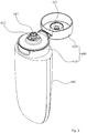
- Fig. 2 is an assembled perspective view illustrating a configuration of a foam-jetting tube container according to an exemplary embodiment.
- Fig.3 is a cross-sectional view illustrating a configurations of a foam-jetting tube container according to an exemplary embodiment.
- a foam-jetting tube container includes a container body 100, a contents movement part 200, an air movement part 300, a housing 400, a valve member 500, and a finish cap 600.
- the container body 100 storing liquid-type contents, is provided with a discharge hole 110 at the upper portion thereof such that the contents can be discharged through.
- the container body 100 can be composed of a tube container or a blow container which can be deformed by user's pressurization and discharge the stored contents by the inner pressure change,
- the contents movement part 200 coupled to the lower portion of an air movement part 300 at the inner side of the discharge hole 110 and functioning as a passage where stored contents and air can move through, is provided with a contents outflow hole 210 at the center portion thereof such that the contents stored in the container body 100 can flow out, and is coupled, at one side of the lower end, with an air movement tube 220 which guides the air stored in the container body 100 to move to the air movement part 300.
- the air movement part 300 coupled to the upper portion of the contents movement part 200 and forms a passage where air moves, is provided with a plurality of air outflow hole 310 separated with a predetermined distance apart such that the air remaining in the container body 100 can flow out to the outside through the air movement tube 220, and is formed with at least more than one first air movement hole 320 such that the outside air can move into the interior of the container body 100.
- a coupling part 330 which is coupled to the first mixing part 410 of the housing 400, wherein at the inner circumferential surface of the coupling part 330 are provided a plurality of coupling protrusions 331 which are coupled with the first mixing part 410 and thereby, form a plurality of air movement grooves 332, such that the air flowing out through the air outflow hole 310 can pass through the air movement grooves 332 and move into the interior of the first mixing part 410.
- valve coupling groove 340 which is disposed between the air outflow hole 310 and the first air movement hole 320 and supports a valve member 500 to be described.
- the housing 400 is coupled to the discharge hole 110 and closes the upper end of the discharge hole 110 at the upper portion of the container body 100.
- a first mixing part 410 which forms a space such that the contents and air stored in the container body 100 are mixed and firstly generate foam
- a second mixing part 420 which is connected with the first mixing part 410 to form a space for secondly generating foam and is equipped with a foam mesh 421 at the inner side thereof.
- a communication groove 411 which is connected with the air movement groove 332 and guides the air flowing through the air movement groove 332 to move to the first mixing part 410, and at the upper end thereof is provided a plurality of communication holes 412 which connect the first mixing part 410 and the second mixing part 420.
- the foam mesh 421 can be composed of various structures for generating enough foam, and, as illustrated in Fig. 3 , can be respectively provided at the upper end and the lower end of a fixation body 422 for fixing the foam mesh 421 at the inner side of the mixing part 420.
- a plurality of second air movement holes 430 which are separated with a predetermined distance apart such that the air flowing into through an air inflow hole 612 of the finish cap 600 can move to the first air movement hole 320.
- the valve 500 coupled to the upper portion of the air movement part 300 and controlling the air movement according to pressurization of the container body 100, is composed of a support body 510 of a cylinder shape which is coupled to a valve coupling groove 340 formed at the upper end of the air movement part 300; a first wing 520 which extends as encasing the inner circumferential surface and opens/closes the air outflow hole 310; and a second wing 530 which extends as encasing the outer circumferential surface of the support body 510 and opens/closes the second air movement hole 430.
- the first wing 520 is configured to be disposed as closing the air outflow hole 310 at a normal state, and then to be separated from the air outflow hole 310 and to open the air outflow hole 310 by the pressure of the air flowing into through the air movement tube 220 when pressurizing the container body 100 in a state of the container body 100 being upside down.
- the second wing 530 is configured to be disposed as closing the air outflow hole 310 at a normal state, and then to be separated from the air outflow hole 310 by the pressure of the air flowing into through the air inflow hole 612 of the finish cap 600 when pressurizing the container body 100 in a state of the container body 100 being upside down and to open the second air movement hole 430.
- the finish cap 600 encasing the housing 400 and coupled to the discharge hole 110, includes a cap body 610 and a cover 620.
- the cap body 610 has a screw thread formed at the inner circumferential surface thereof for being screw-coupled to the discharge hole 110, wherein a foam-jetting hole 611 is formed at the center portion of the upper end thereof such that the foam generated through the first mixing part 410 and the second fixing part 420 can be jetted.
- the cap body 610 is formed more than one air inflow holes 612 which surround the foam-jetting hole 611.
- the outside air flowing into through the air inflow hole 612 passes through a first air movement hole 320, and then moves into the interior of the container body 100 through the air movement tube 220.
- the cover 620 which is hinge-coupled to one side of the cap body 610 and opens/closes the foam-jetting hole 611, is preferably provided, at the inner side thereof, with a closing protrusion 621 which closes the foam-jetting hole 611 and thereby prevents the contents from being leaked.
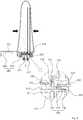
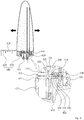
- FIGS. 4 and Fig. 5 are views illustrating an operational state of a foam-jetting tube container according to an exemplary embodiment.
- a foam-jetting tube container when a user pressurizes a container body 100 while holding the container body 100 in an upside-down position, the contents stored in the container body 100 flow into the first mixing part 410 through the contents outflow hole 210, and the air existing in the container body 100 simultaneously flows into the first mixing part 410 through the air movement tube 220. Due to this, the contents and air are mixed in the first mixing part 410 and are firstly generated into foam.
- the air moving through the air movement tube 220 passes through the air outflow hole 310 and further passes through the air movement groove 332 and the communication groove 411, and then flows into the first mixing part 410.
- the first wing 520 is disposed as closing the air outflow hole 310 at a normal state, and then, is separated from the air outflow hole 310 and opens the air outflow hole 310 to make the air existing in the container body 100 move to the first mixing part 410 by the pressure of the air moving through the air movement tube 220 when the container body 100 is pressurized in a state of being upside down.
- the foam firstly generated in the interior of the first mixing part 410 moves to the second mixing part 420 through the communication hole 412.
- foam is secondly generated as passing through the foam mesh 421 provided at the inner side of the second mixing part 420, and then is jetted to the outside through the foam-jetting hole 611.
- the container body 100 is depressurized in a state of foam-jetting being completed, the inner pressure of the container body 100 is released as illustrated in Fig. 5 , and the second wing 520 is separated from the second air movement hole 430 by the pressure of air flowing into through the air inflow hole 612 and then opens the second air movement hole 430. Therefore, the air flowing into through the air inflow hole 612 passes through the second air movement hole 430, passing through the first air movement hole 320, and moves to the air movement tube 220, such that the air can be stored in the interior of the container body 100.
- the present invention is composed of an air inflowing structure such that air can flow into without being contacted with contents in a process of flowing into the container body 100. Therefore, it is possible to fundamentally solve the problem wherein air is generated in the interior of the container body 100 by the contact with contents in a process of the air flowing into through an traditional ball valve or a check valve.
Landscapes
- Engineering & Computer Science (AREA)
- Mechanical Engineering (AREA)
- Ceramic Engineering (AREA)
- Closures For Containers (AREA)
- Containers And Packaging Bodies Having A Special Means To Remove Contents (AREA)
Abstract
Description
- The present invention relates to a foam-jetting tube container configured in that, when a container body is pressurized in a state of the container body being turned upside down, contents and air stored inside the container body flow into a first mixing part and are mixed so as to firstly form foam, and then are secondarily formed into foam through a foam mesh while passing through a second mixing part which communicates with the first mixing part, and then discharged to the outside, such that the foam can be jetted by means of a simple structure.
- Generally, a foam-jetting tube container refers to a container having a structure wherein a user pressurizes a container body with contents stored and makes the container form foam in the process of discharging the contents by mixing with outside air.
- A foam-jetting tube container as described in the above is disclosed in the Korean Registered Patent No.
10-1067748 - The registered patent, which the present applicant filed on October 09, 2009 and was registered as such, comprises a first container body containing contents; an inner container combined to an upper portion of the first container body and comprising a first tube neck to which a hollow is formed so as for the contents to be discharged; an outer container, which is combined to the inner container as encasing, comprising a second tube neck combined at an upper portion thereof, separated from the inner container with a constant distance and forming a space, which forms a multitude of first air holes separated with a constant distance; an inner cap which is combined to an upper portion of the outer container, comprising a multitude of second air holes separated with constant distance at an upper end thereof; a support cap which is combined to the inner cap at a lower portion of the second tube neck, comprising a protrusion wherein a multitude of third air holes are formed with a constant distance separated at a side thereof; a check valve combined to a lower portion of the support cap directly above the hollow and preventing reflux of content; an air valve which is combined, encasing a lower end of the second air holes and an inner circumferential surface of the support cap in an interior of the inner cap and, made of elastic material, opens/closes either the second air hole or a third air hole according to movement of air; and an outer cap which is combined, encasing the inner cap, comprising a foam mesh at an end of the center thereof.
- However, the registered patent has some problems in that the container should be equipped with double tubes in order to make a space where air flows in to be kept, such that the manufacturing time and cost increase due to the complicated air inflowing structure to be equipped, thereby incurring burden to users.
- The present disclosure is directed to solving the problems in the above, and the objectives of the disclosed embodiments are to provide a foam-jetting tube container in that, when a container body is pressurized in a state of the container body being turned upside down, contents and air stored inside the container body flow into a first mixing part and are mixed so as to firstly form foam, and then are secondarily formed into foam through a foam mesh while passing through a second mixing part which communicates with the first mixing part, and then discharged to the outside, such that the foam can be jetted by means of a simple structure.
- To solve the above problems, a foam-jetting tube container according to the disclosed embodiments includes: a container body storing contents and having a discharge hole formed at the upper portion thereof, deformed by user's pressurization, and discharging contents through the discharge hole; a contents movement part disposed at the inner side of the discharge hole and coupled with an air movement tube which functions as an air movement passage at the lower portion thereof, and provided with a contents outflow hole such that contents stored in the container body at the center portion thereof can flow out; an air movement part, coupled to the upper portion of the contents movement part, provided with an air outflow hole such that air remaining in the container body can flow out to the outside through the air movement tube, and further, provided with a first air movement hole such that the outside air can flow into the inside of the container body; a housing coupled to the discharge hole, and comprising a first mixing part forming a space where contents and air stored in the container body are mixed and then firstly formed to foam, and provided with a second mixing part which is connected with the first mixing part and forms a space where foam is secondarily formed; a valve member coupled to the upper portion of the air movement part and controlling the air movement according to the pressurization of the container body; and a finish cap encasing the housing and coupled to the discharge hole, and provided with a foam-jetting hole where the foam which is formed while passing through the first mixing part and the second mixing part can be jetted through.
- Furthermore, it is characterized in that an air inflow hole is provided at the finish cap such that the outside air can flow in, and a second air movement hole is provided at the housing such that the air flowing into through the air inflow hole can move to the first air movement hole.
- Furthermore, it is characterized in that the valve member includes a support body of a cylindrical shape coupled to the upper portion of the air movement part, a first wing extending and encasing the inner circumferential surface of the support body and opening/closing the air outflow hole, and a second wing extending
- Furthermore, it is characterized in that the first wing is separated from the air outflow hole and opens the air outflow hole by the air pressure moving through the air movement tube when the container body is pressurized in a state of the container body being upside down, and the second wing is separated from the second air movement hole and opens the second air movement hole by the air pressure flowing in through the air inflow hole when the container body is depressurized.
- Furthermore, it is characterized in that a plurality of air movement grooves are longitudinally provided at the inner circumferential surface of the air movement part such that the air flowing out through the air outflow hole moves into the interior of the first mixing part.
- Furthermore, it is characterized in that at the inner side of the first mixing part is provided a communication groove which is connected with the air movement groove and guides the air moving through the air movement groove to move to the first mixing part.
- Furthermore, it is characterized in that at the upper end of the first mixing part is provided a plurality of communication grooves which connect the first mixing part and the second mixing part.
- As described as the above, the presently described embodiments are configured in that, when a container body is pressurized in a state of the container body being turned upside down, contents and air stored inside the container body flow into a first mixing part and are mixed so as to firstly form foam, and then are secondarily formed into foam through a foam mesh while passing through a second mixing part which communicates with the first mixing part, and then discharged to the outside, such that the foam can be jetted by means of a simple structure.
-
-
Fig.1 is an exploded perspective view illustrating a configuration of a foam-jetting tube container according to an exemplary embodiment. -
Fig. 2 is an assembled perspective view illustrating a configuration of a foam-jetting tube container according to an exemplary embodiment. -
Fig.3 is a cross-sectional view illustrating a configurations of a foam-jetting tube container according to an exemplary embodiment. -
Figs. 4 andFig. 5 are views illustrating an operational state of a foam-jetting tube container according to an exemplary embodiment. - Hereinafter, exemplary embodiments will be described in detail with reference to the accompanying drawings. The same reference numerals provided in the drawings indicate the same members.
-
Fig.1 is an exploded perspective view illustrating a configuration of a foam-jetting tube container according to an exemplary embodiment.Fig. 2 is an assembled perspective view illustrating a configuration of a foam-jetting tube container according to an exemplary embodiment.Fig.3 is a cross-sectional view illustrating a configurations of a foam-jetting tube container according to an exemplary embodiment. - Referring to
Figs.1 to 3 , a foam-jetting tube container according to an exemplary embodiment includes acontainer body 100, acontents movement part 200, anair movement part 300, ahousing 400, avalve member 500, and afinish cap 600. - The
container body 100, storing liquid-type contents, is provided with adischarge hole 110 at the upper portion thereof such that the contents can be discharged through. - The
container body 100 can be composed of a tube container or a blow container which can be deformed by user's pressurization and discharge the stored contents by the inner pressure change, - The
contents movement part 200, coupled to the lower portion of anair movement part 300 at the inner side of thedischarge hole 110 and functioning as a passage where stored contents and air can move through, is provided with acontents outflow hole 210 at the center portion thereof such that the contents stored in thecontainer body 100 can flow out, and is coupled, at one side of the lower end, with anair movement tube 220 which guides the air stored in thecontainer body 100 to move to theair movement part 300. - The
air movement part 300, coupled to the upper portion of thecontents movement part 200 and forms a passage where air moves, is provided with a plurality ofair outflow hole 310 separated with a predetermined distance apart such that the air remaining in thecontainer body 100 can flow out to the outside through theair movement tube 220, and is formed with at least more than one firstair movement hole 320 such that the outside air can move into the interior of thecontainer body 100. - Meanwhile, at the center portion of the
air movement part 300 is provided acoupling part 330 which is coupled to thefirst mixing part 410 of thehousing 400, wherein at the inner circumferential surface of thecoupling part 330 are provided a plurality ofcoupling protrusions 331 which are coupled with the first mixingpart 410 and thereby, form a plurality ofair movement grooves 332, such that the air flowing out through theair outflow hole 310 can pass through theair movement grooves 332 and move into the interior of thefirst mixing part 410. - Furthermore, at the upper end of the
air movement part 300 is provided avalve coupling groove 340 which is disposed between theair outflow hole 310 and the firstair movement hole 320 and supports avalve member 500 to be described. - The
housing 400 is coupled to thedischarge hole 110 and closes the upper end of thedischarge hole 110 at the upper portion of thecontainer body 100. In the presently described embodiments, at the center portion of thehousing 400 is provided afirst mixing part 410 which forms a space such that the contents and air stored in thecontainer body 100 are mixed and firstly generate foam, and furthermore, is provided a second mixingpart 420 which is connected with the first mixingpart 410 to form a space for secondly generating foam and is equipped with afoam mesh 421 at the inner side thereof. - At the inner side of the
first mixing part 410 is provided acommunication groove 411 which is connected with theair movement groove 332 and guides the air flowing through theair movement groove 332 to move to thefirst mixing part 410, and at the upper end thereof is provided a plurality ofcommunication holes 412 which connect thefirst mixing part 410 and the second mixingpart 420. After the contents and air stored in thecontainer body 100 pass through thecommunication hole 412 and are firstly generated into foam in a process of moving up to the upper portion, the foam firstly generated passes through thecommunication hole 412 and goes through afoam mesh 421 installed at the inner side of the second mixingpart 420 and then, are secondly generated into foam. - The
foam mesh 421 can be composed of various structures for generating enough foam, and, as illustrated inFig. 3 , can be respectively provided at the upper end and the lower end of afixation body 422 for fixing thefoam mesh 421 at the inner side of themixing part 420. - Meanwhile, at the
housing 400 is provided a plurality of secondair movement holes 430 which are separated with a predetermined distance apart such that the air flowing into through anair inflow hole 612 of thefinish cap 600 can move to the firstair movement hole 320. - The
valve 500, coupled to the upper portion of theair movement part 300 and controlling the air movement according to pressurization of thecontainer body 100, is composed of asupport body 510 of a cylinder shape which is coupled to avalve coupling groove 340 formed at the upper end of theair movement part 300; afirst wing 520 which extends as encasing the inner circumferential surface and opens/closes theair outflow hole 310; and asecond wing 530 which extends as encasing the outer circumferential surface of thesupport body 510 and opens/closes the secondair movement hole 430. Thefirst wing 520 is configured to be disposed as closing theair outflow hole 310 at a normal state, and then to be separated from theair outflow hole 310 and to open theair outflow hole 310 by the pressure of the air flowing into through theair movement tube 220 when pressurizing thecontainer body 100 in a state of thecontainer body 100 being upside down. Meanwhile, thesecond wing 530 is configured to be disposed as closing theair outflow hole 310 at a normal state, and then to be separated from theair outflow hole 310 by the pressure of the air flowing into through theair inflow hole 612 of thefinish cap 600 when pressurizing thecontainer body 100 in a state of thecontainer body 100 being upside down and to open the secondair movement hole 430. - The
finish cap 600, encasing thehousing 400 and coupled to thedischarge hole 110, includes acap body 610 and acover 620. - The
cap body 610 has a screw thread formed at the inner circumferential surface thereof for being screw-coupled to thedischarge hole 110, wherein a foam-jetting hole 611 is formed at the center portion of the upper end thereof such that the foam generated through the first mixingpart 410 and thesecond fixing part 420 can be jetted. - Meanwhile, at the upper end of the
cap body 610 is formed more than oneair inflow holes 612 which surround the foam-jetting hole 611. The outside air flowing into through theair inflow hole 612 passes through a firstair movement hole 320, and then moves into the interior of thecontainer body 100 through theair movement tube 220. - The
cover 620, which is hinge-coupled to one side of thecap body 610 and opens/closes the foam-jetting hole 611, is preferably provided, at the inner side thereof, with aclosing protrusion 621 which closes the foam-jetting hole 611 and thereby prevents the contents from being leaked. - Hereafter, with a reference of
Figs. 4 andFig. 5 , a foam-jetting process of a foam-jetting tube container according to exemplary embodiments will be described.Figs. 4 andFig. 5 are views illustrating an operational state of a foam-jetting tube container according to an exemplary embodiment. - First, referring to
Fig. 3 , a foam-jetting tube container according to an exemplary embodiment, when a user pressurizes acontainer body 100 while holding thecontainer body 100 in an upside-down position, the contents stored in thecontainer body 100 flow into the first mixingpart 410 through thecontents outflow hole 210, and the air existing in thecontainer body 100 simultaneously flows into thefirst mixing part 410 through theair movement tube 220. Due to this, the contents and air are mixed in thefirst mixing part 410 and are firstly generated into foam. - The air moving through the
air movement tube 220 passes through theair outflow hole 310 and further passes through theair movement groove 332 and thecommunication groove 411, and then flows into thefirst mixing part 410. Thefirst wing 520 is disposed as closing theair outflow hole 310 at a normal state, and then, is separated from theair outflow hole 310 and opens theair outflow hole 310 to make the air existing in thecontainer body 100 move to thefirst mixing part 410 by the pressure of the air moving through theair movement tube 220 when thecontainer body 100 is pressurized in a state of being upside down. - Next, the foam firstly generated in the interior of the first mixing
part 410 moves to the second mixingpart 420 through thecommunication hole 412. At this time, foam is secondly generated as passing through thefoam mesh 421 provided at the inner side of the second mixingpart 420, and then is jetted to the outside through the foam-jetting hole 611. - As in the above, if the
container body 100 is depressurized in a state of foam-jetting being completed, the inner pressure of thecontainer body 100 is released as illustrated inFig. 5 , and thesecond wing 520 is separated from the secondair movement hole 430 by the pressure of air flowing into through theair inflow hole 612 and then opens the secondair movement hole 430. Therefore, the air flowing into through theair inflow hole 612 passes through the secondair movement hole 430, passing through the firstair movement hole 320, and moves to theair movement tube 220, such that the air can be stored in the interior of thecontainer body 100. - The present invention is composed of an air inflowing structure such that air can flow into without being contacted with contents in a process of flowing into the
container body 100. Therefore, it is possible to fundamentally solve the problem wherein air is generated in the interior of thecontainer body 100 by the contact with contents in a process of the air flowing into through an traditional ball valve or a check valve. - As described above, optimal embodiments have been disclosed in the drawings and the specification. Although specific terms have been used herein, these are only intended to describe certain embodiments and are not intended to limit the meanings of the terms or to restrict the scope of the accompanying claims. Therefore, those skilled in the art will appreciate that various modifications and other equivalent embodiments are possible from the above embodiments. Therefore, the scope of the claims should be defined by the technical spirit of the description above.
Claims (7)
- a foam-jetting tube container, comprising:a container body (100) storing contents and having a discharge hole (110) formed at the upper portion thereof, deformed by user's pressurization, and discharging contents through the discharge hole (110);a contents movement part (200) disposed at the inner side of the discharge hole (110) and coupled with an air movement tube (220) functioning as an air movement passage at the lower portion thereof, and provided with a contents outflow hole (210) such that contents stored in the container body (100) at the center portion thereof can flow out;an air movement part (300), coupled to the upper portion of the contents movement part (200), provided with an air outflow hole (310) such that air remaining in the container body (100) can flow out to the outside through the air movement tube (220), and further provided with a first air movement hole (320) such that the outside air can flow into the inside of the container body (100);a housing (400) coupled to the discharge hole (110), and comprising a first mixing part (410) forming a space where contents and air stored in the container body (100) are mixed and then firstly formed to foam, and a second mixing part (420) which is connected with the first mixing part (410) and forms a space where foam is secondarily formed;a valve member (500) coupled to the upper portion of the air movement part (300) and controlling the air movement according to the pressurization of the container body (100); anda finish cap (600) encasing the housing (400) and coupled to the discharge hole (110), and provided with a foam-jetting hole (611) where the foam formed while passing through the first mixing part (410) and the second mixing part (420) can be jetted through.
- The foam-jetting tube container of claim 1,
characterized in that an air inflow hole (612) is provided at the finish cap (600) such that the outside air can flow in, and a second air movement hole (430) is provided at the housing (400) such that the air flowing into through the air inflow hole (612) can move to the first air movement hole (320). - The foam-jetting tube container of claim 2,
characterized in that the valve member (500) includes a support body (510) of a cylindrical shape coupled to the upper portion of the air movement part (300), a first wing (520) extending and encasing the inner circumferential surface of the support body (510) and opening/closing the air outflow hole (310), and a second wing (530) extending as encasing the outer circumferential surface of the support body (510) and opening/closing the second air movement hole (430). - The foam-jetting tube container of claim 3,
characterized in that the first wing (520) is separated from the air outflow hole (310) and opens the air outflow hole (310) by the air pressure moving through the air movement tube (220) when the container body (100) is pressurized in a state of the container body (100) being upside down, and the second wing (530) is separated from the second air movement hole (430) and opens the second air movement hole (430) by the air pressure flowing in through the air inflow hole (612) when the container body (100) is depressurized. - The foam-jetting tube container of claim 1,
characterized in that a plurality of air movement grooves (332) are longitudinally provided at the inner circumferential surface of the air movement part (300) such that the air flowing out through the air outflow hole (310) moves into the interior of the first mixing part (410). - The foam-jetting tube container of claim 5,
characterized in that at the inner side of the first mixing part (410) is provided a communication groove (411) which is connected with the air movement groove (332) and guides the air moving through the air movement groove (332) to move to the first mixing part (410). - The foam-jetting tube container of claim 6,
characterized in that at the upper end of the first mixing part (410) is provided a plurality of communication grooves (411) which connect the first mixing part (410) and the second mixing part (420).
Applications Claiming Priority (2)
| Application Number | Priority Date | Filing Date | Title |
|---|---|---|---|
| KR1020150137316A KR101737866B1 (en) | 2015-09-30 | 2015-09-30 | Tube vessel for bubble spouting |
| PCT/KR2016/007459 WO2017057830A1 (en) | 2015-09-30 | 2016-07-08 | Foam-jetting tube container |
Publications (2)
| Publication Number | Publication Date |
|---|---|
| EP3357827A1 true EP3357827A1 (en) | 2018-08-08 |
| EP3357827A4 EP3357827A4 (en) | 2019-05-08 |
Family
ID=58424167
Family Applications (1)
| Application Number | Title | Priority Date | Filing Date |
|---|---|---|---|
| EP16851978.3A Withdrawn EP3357827A4 (en) | 2015-09-30 | 2016-07-08 | TUBULAR FOAM EJECTION CONTAINER |
Country Status (6)
| Country | Link |
|---|---|
| US (1) | US20180290785A1 (en) |
| EP (1) | EP3357827A4 (en) |
| JP (1) | JP2018532659A (en) |
| KR (1) | KR101737866B1 (en) |
| CN (1) | CN108025838A (en) |
| WO (1) | WO2017057830A1 (en) |
Families Citing this family (6)
| Publication number | Priority date | Publication date | Assignee | Title |
|---|---|---|---|---|
| CN109689517B (en) * | 2016-07-07 | 2020-07-14 | 奈特包装有限责任公司 | Multi-lumen tube containers and caps |
| USD876902S1 (en) * | 2017-04-03 | 2020-03-03 | HumanGear, Inc. | Dispensing container |
| JP6589158B1 (en) * | 2019-05-23 | 2019-10-16 | 株式会社ベッセル・ジャパン | Air bagless structure |
| USD926578S1 (en) * | 2019-10-11 | 2021-08-03 | Yonwoo Co., Ltd. | Pumping vessel for packaging container |
| JP7584753B2 (en) * | 2020-06-02 | 2024-11-18 | 株式会社フォーティー科研 | Bubble generating device and bubble generating method |
| KR102525464B1 (en) * | 2021-01-27 | 2023-04-24 | 최정구 | Containers with backflow prevention structure in bubble generation structure |
Family Cites Families (12)
| Publication number | Priority date | Publication date | Assignee | Title |
|---|---|---|---|---|
| US3709437A (en) * | 1968-09-23 | 1973-01-09 | Hershel Earl Wright | Method and device for producing foam |
| CH557160A (en) * | 1972-07-03 | 1974-12-31 | Ritter Gustav | Foam dispenser for shaving purposes - has two relatively moving cylinders for actuating dispensing valve in brush head |
| EP1873076B1 (en) * | 1994-11-17 | 2012-01-25 | Yoshino Kogyosho Co., Ltd. | Container with pump for discharging bubbles |
| JPH11105907A (en) * | 1997-10-09 | 1999-04-20 | Kao Corp | Foam discharge container |
| US6644516B1 (en) * | 2002-11-06 | 2003-11-11 | Continental Afa Dispensing Company | Foaming liquid dispenser |
| JP2011098777A (en) | 2009-10-06 | 2011-05-19 | Takeuchi Press Ind Co Ltd | Jet tube container for foamy substance |
| KR101067748B1 (en) | 2009-10-09 | 2011-09-28 | (주)연우 | Foam Blowing Tube Container |
| JP2012158391A (en) | 2011-01-12 | 2012-08-23 | Takeuchi Press Ind Co Ltd | Bubble-like substance jetting tube vessel |
| WO2013151320A1 (en) * | 2012-04-03 | 2013-10-10 | Lee Gwon Haeng | Stopper structure having a bubble-generating unit |
| JP5859408B2 (en) * | 2012-08-30 | 2016-02-10 | 株式会社吉野工業所 | Foam ejection container |
| WO2015099338A1 (en) * | 2013-12-26 | 2015-07-02 | (주)연우 | Foam jetting tube container |
| KR101517825B1 (en) * | 2014-06-02 | 2015-05-06 | 주식회사 아폴로산업 | Foaming generater for squeeze bottle |
-
2015
- 2015-09-30 KR KR1020150137316A patent/KR101737866B1/en not_active Expired - Fee Related
-
2016
- 2016-07-08 CN CN201680056280.5A patent/CN108025838A/en active Pending
- 2016-07-08 JP JP2018516494A patent/JP2018532659A/en active Pending
- 2016-07-08 US US15/764,574 patent/US20180290785A1/en not_active Abandoned
- 2016-07-08 WO PCT/KR2016/007459 patent/WO2017057830A1/en not_active Ceased
- 2016-07-08 EP EP16851978.3A patent/EP3357827A4/en not_active Withdrawn
Also Published As
| Publication number | Publication date |
|---|---|
| US20180290785A1 (en) | 2018-10-11 |
| CN108025838A (en) | 2018-05-11 |
| WO2017057830A1 (en) | 2017-04-06 |
| KR101737866B1 (en) | 2017-05-19 |
| KR20170038243A (en) | 2017-04-07 |
| EP3357827A4 (en) | 2019-05-08 |
| JP2018532659A (en) | 2018-11-08 |
Similar Documents
| Publication | Publication Date | Title |
|---|---|---|
| US20180290785A1 (en) | Foam-jetting tube container | |
| EP3088322A1 (en) | Foam jetting tube container | |
| KR102606815B1 (en) | Discharge container that discharges contents onto the discharge surface | |
| JP6170251B2 (en) | Tube-type cosmetic container that discharges liquid contents in drops | |
| US20170291185A1 (en) | Dispenser Container | |
| US20180263359A1 (en) | Rotary Discharge Type Dye Container | |
| KR101067748B1 (en) | Foam Blowing Tube Container | |
| US20190021470A1 (en) | Cosmetic container with double discharge means | |
| US20180079584A1 (en) | Mixing container for heterogeneous content | |
| US20180127171A1 (en) | Mixing container for heterogeneous content | |
| US20170136478A1 (en) | Pump container for discharging capsules | |
| KR101663206B1 (en) | Dispenser | |
| JP4753233B2 (en) | Metering container | |
| IT201600068705A1 (en) | CONTAINER FOR LIQUID ASSOCIATED WITH A GASER | |
| US10470548B2 (en) | Cosmetic container having identification means | |
| US10934077B2 (en) | Powder dispensing container | |
| EP2835322A1 (en) | Tube vessel capable of preventing air infiltration | |
| KR101910060B1 (en) | Tube vessel for bubble spouting | |
| KR101618122B1 (en) | Tube vessel | |
| JP6363045B2 (en) | Double container | |
| JP6465776B2 (en) | Double container | |
| KR101598043B1 (en) | Tube vessel for bubble spouting | |
| JP6297442B2 (en) | Double container | |
| JP6322514B2 (en) | Squeeze discharge container | |
| JP2002068256A (en) | Bubble discharging pump container |
Legal Events
| Date | Code | Title | Description |
|---|---|---|---|
| STAA | Information on the status of an ep patent application or granted ep patent |
Free format text: STATUS: THE INTERNATIONAL PUBLICATION HAS BEEN MADE |
|
| PUAI | Public reference made under article 153(3) epc to a published international application that has entered the european phase |
Free format text: ORIGINAL CODE: 0009012 |
|
| STAA | Information on the status of an ep patent application or granted ep patent |
Free format text: STATUS: REQUEST FOR EXAMINATION WAS MADE |
|
| 17P | Request for examination filed |
Effective date: 20180329 |
|
| AK | Designated contracting states |
Kind code of ref document: A1 Designated state(s): AL AT BE BG CH CY CZ DE DK EE ES FI FR GB GR HR HU IE IS IT LI LT LU LV MC MK MT NL NO PL PT RO RS SE SI SK SM TR |
|
| AX | Request for extension of the european patent |
Extension state: BA ME |
|
| DAV | Request for validation of the european patent (deleted) | ||
| DAX | Request for extension of the european patent (deleted) | ||
| A4 | Supplementary search report drawn up and despatched |
Effective date: 20190410 |
|
| RIC1 | Information provided on ipc code assigned before grant |
Ipc: B65D 47/32 20060101ALI20190404BHEP Ipc: B65D 85/73 20060101ALI20190404BHEP Ipc: B65D 35/44 20060101AFI20190404BHEP |
|
| STAA | Information on the status of an ep patent application or granted ep patent |
Free format text: STATUS: THE APPLICATION IS DEEMED TO BE WITHDRAWN |
|
| 18D | Application deemed to be withdrawn |
Effective date: 20191112 |