JP2012158391A - Bubble-like substance jetting tube vessel - Google Patents

Bubble-like substance jetting tube vessel Download PDF

Info

Publication number
JP2012158391A
JP2012158391A JP2011253984A JP2011253984A JP2012158391A JP 2012158391 A JP2012158391 A JP 2012158391A JP 2011253984 A JP2011253984 A JP 2011253984A JP 2011253984 A JP2011253984 A JP 2011253984A JP 2012158391 A JP2012158391 A JP 2012158391A
Authority
JP
Japan
Prior art keywords
tube container
cylinder
tube
outside air
lid
Prior art date
Legal status (The legal status is an assumption and is not a legal conclusion. Google has not performed a legal analysis and makes no representation as to the accuracy of the status listed.)
Pending
Application number
JP2011253984A
Other languages
Japanese (ja)
Inventor
Takami Sawada
孝美 澤田
Masaru Kiyoshige
優 清重
Takahiro Murase
貴浩 村瀬
Current Assignee (The listed assignees may be inaccurate. Google has not performed a legal analysis and makes no representation or warranty as to the accuracy of the list.)
Takeuchi Press Industries Co Ltd
Original Assignee
Takeuchi Press Industries Co Ltd
Priority date (The priority date is an assumption and is not a legal conclusion. Google has not performed a legal analysis and makes no representation as to the accuracy of the date listed.)
Filing date
Publication date
Application filed by Takeuchi Press Industries Co Ltd filed Critical Takeuchi Press Industries Co Ltd
Priority to JP2011253984A priority Critical patent/JP2012158391A/en
Publication of JP2012158391A publication Critical patent/JP2012158391A/en
Pending legal-status Critical Current

Links

Images

Landscapes

  • Containers And Packaging Bodies Having A Special Means To Remove Contents (AREA)
  • Closures For Containers (AREA)

Abstract

PROBLEM TO BE SOLVED: To provide a bubble-like substance jetting tube vessel, which can surely inject the contents by foaming them in a bubble shape, can be opened and closed in a single operation with one hand, and convenient for carrying.SOLUTION: In this bubble-like substance jetting tube vessel, a bubble generator 3 for fitting a dip tube 5 to an outer peripheral surface of an opening end part is installed in a port part 2 of a tube vessel 1 having elastic restoring force, a mesh 5a is arranged in the dip tube 5, an outside air inflow passage 4 is formed, and an inner flow passage 6 is arranged for communicating the mesh 5a with the inside of the tube vessel 1 via the dip tube 5.

Description

本発明は泡状物質噴出チューブ容器に関し、さらに詳しくは確実に内容物を泡状に発泡して注出でき、片手のワンタッチ操作で開閉できると共に、持ち運びに便利な泡状物質噴出チューブ容器に関する。   The present invention relates to a foam material ejection tube container, and more particularly, to a foam material ejection tube container that can be foamed and poured out with certainty, can be opened and closed with a one-handed one-touch operation, and is easy to carry.

従来、弾性復元が可能な胴部を有するチューブ容器の口部に、泡状物質注出機構を有する蓋体が螺合されたチューブ容器が市場で販売されている。このようなチューブ容器内には、ヘアークリーム、ヘアームース等の化粧品、消毒液等の薬剤、シェービングクリーム等のビューティケア製品又は食品等の内容物が充填され、使用時に空気と内容物を多孔性部材内に供給して混合し、この多孔性部材内で泡状物質に発泡させて泡状物質を注出するものである。このような従来の泡状物質噴出チューブ容器としては、図9〜図11に示すようなものがある。   2. Description of the Related Art Conventionally, a tube container in which a lid body having a foamy substance extraction mechanism is screwed into a mouth portion of a tube container having a body portion that can be elastically restored is on the market. Such tube containers are filled with contents such as cosmetics such as hair cream, hair mousse, chemicals such as disinfectant, beauty care products such as shaving cream, or foods, and the air and contents are made porous when used. It is supplied into the member and mixed, and foamed into the foam material in this porous member, and the foam material is poured out. Examples of such conventional foamed substance ejection tube containers include those shown in FIGS.

図9中、50は、圧搾及び弾性復元力が可能な胴部を有するチューブ容器であり、51は、外周に雄ねじが形成された口部である。このチューブ容器50は、ポリエチレン等のポリオレフィン系樹脂、ナイロン等のポリアミド樹脂等の単層又は多層構造の材料で造られている。チューブ容器50の胴部を押圧状態から解放すると、エアーバックすることにより、外気流入路52から空気が流入する。そして、空気が内容液53内を通過する際に、内容液53と混合し、その上部空間54で発泡して泡状物質を形成する。発泡した泡状物質は、泡発生装置57の開口端部57aの外周に嵌合された、ディップチューブ55の内流路56を通り、泡発生装置57に供給される。そして、泡発生装置57に設けられたメッシュ58によりさらに大きく発泡され、外部に注出される。このようなチューブ容器の従来の特許文献としては、特許文献1がある。   In FIG. 9, 50 is a tube container which has a trunk | drum which can be squeezed and elastic restoring force, 51 is a mouth part by which the external thread was formed in the outer periphery. The tube container 50 is made of a single-layer or multi-layer material such as a polyolefin resin such as polyethylene or a polyamide resin such as nylon. When the body portion of the tube container 50 is released from the pressed state, air flows in from the outside air inflow path 52 by performing air back. When the air passes through the content liquid 53, it mixes with the content liquid 53 and foams in the upper space 54 to form a foamy substance. The foamed foam material passes through the inner flow path 56 of the dip tube 55 fitted to the outer periphery of the open end 57a of the foam generating device 57, and is supplied to the foam generating device 57. Then, the foam is further expanded by the mesh 58 provided in the foam generating device 57 and poured out to the outside. There exists patent document 1 as a conventional patent document of such a tube container.

特開2011−98777号公報JP 2011-98777 A

しかし、このような従来のチューブ容器50は、メッシュ58が、泡発生装置57の開口部に設けられているため、図10に示すように、チューブ容器50を横にした場合、ディップチューブ55の内流路56内に内容液53が入り込み、水溶液のまま、泡発生装置57に供給される。そのため、最初の噴出時及び再噴出時の際、泡発生装置57から水溶液状の内容物が流出するという欠点があった。これは、ディップチューブ55の内流路56内に溜まった空気又は泡状物質と、内容液53が接したとき、両者が置換することが原因と考えられる。
この発明は、このような課題に着目してなされたものであり、チューブ容器に泡状物質噴出機能を取り付け、最初から泡状物質を確実に注出できる泡状物質噴出チューブ容器を提供することを目的とし、さらに、片手でワンタッチ操作で開閉することができ、バッグ等の中に入れて持ち運びができる、便利な泡状物質噴出チューブ容器を提供することを目的とする。
However, in such a conventional tube container 50, since the mesh 58 is provided in the opening of the foam generating device 57, when the tube container 50 is placed sideways as shown in FIG. The content liquid 53 enters the inner flow path 56 and is supplied to the foam generating device 57 as an aqueous solution. For this reason, there is a drawback in that the content in the form of an aqueous solution flows out from the bubble generating device 57 at the time of the first ejection and the re-ejection. This is considered to be caused by the fact that when the content liquid 53 comes into contact with the air or foamy substance accumulated in the inner flow path 56 of the dip tube 55, both of them are replaced.
The present invention has been made paying attention to such a problem, and provides a foam material ejection tube container that can attach a foam material ejection function to a tube container and can reliably dispense the foam material from the beginning. Furthermore, it is an object of the present invention to provide a convenient foam-like substance ejection tube container that can be opened and closed with one hand with one hand and can be carried in a bag or the like.

この課題を解決するため、請求項1記載の発明の解決手段は、弾性復元力を有するチューブ容器の口部に、開口端部の外周面にディップチューブが嵌合された泡発生装置が装着され、ディップチューブにメッシュが設けられると共に外気流入路を形成し、ディップチューブを介して、メッシュとチューブ容器内とを連通する、内流路を設けたことを特徴とする泡状物質噴出チューブ容器である。   In order to solve this problem, the solution means of the invention described in claim 1 is equipped with a foam generating device in which a dip tube is fitted to the outer peripheral surface of the opening end portion at the mouth portion of the tube container having elastic restoring force. A foam material jet tube container characterized in that a mesh is provided in the dip tube and an outside air inflow passage is formed, and an internal flow path is provided to communicate the mesh and the inside of the tube container via the dip tube. is there.

この課題を解決するため、請求項2記載の発明の解決手段は、泡発生装置の先端に、鍔部を形成することを特徴とする泡状物質噴出チューブ容器である。   In order to solve this problem, the solution means of the invention according to claim 2 is a foam material jet tube container characterized in that a flange is formed at the tip of the foam generating device.

この課題を解決するため、請求項3記載の発明の解決手段は、泡状物質噴出チューブ容器の口部に、ヒンジキャップが螺合又は嵌合されることを特徴とする泡状物質噴出チューブ容器である。   In order to solve this problem, the solution means of the invention described in claim 3 is characterized in that a foam cap member is characterized in that a hinge cap is screwed or fitted into the mouth portion of the spout tube portion. It is.

この課題を解決するため、請求項4記載の発明の解決手段は、ヒンジキャップは、チューブ容器の口部に装着される基幹筒体と、該基幹筒体とヒンジを介して連結される蓋体からなり、(a)基幹筒体は、蓋体を開けるために押圧操作されうる弾片部及び係止片を有する外筒と、外筒の内側に形成され、チューブ容器の口部に螺合又は嵌合される内筒と、内筒の天面に形成され泡状物質を噴出する注出口とからなり、(b)蓋体は、外筒の係止片と係脱自在に係合する係止片及び蓋体を一定角度押し上げる三角片を有し、嵌合筒が基幹筒体の注出口に係脱自在に係合することを特徴とする泡状物質墳出チューブ容器である。   In order to solve this problem, according to a fourth aspect of the present invention, the hinge cap includes a trunk cylinder that is attached to the mouth of the tube container, and a lid that is coupled to the trunk cylinder via the hinge. (A) The trunk cylinder is formed on the inner side of the outer cylinder and the outer cylinder having an elastic piece and a locking piece that can be pressed to open the lid, and is screwed into the mouth of the tube container. Or it consists of the inner cylinder fitted and the spout formed in the top | upper surface of an inner cylinder, and ejects a foam-like substance, (b) A cover body engages with the latching piece of an outer cylinder removably. It is a foaming substance discharge tube container having a triangular piece that pushes up a locking piece and a lid at a certain angle, and a fitting cylinder detachably engages with a spout of a trunk cylinder.

この課題を解決するため、請求項5記載の発明の解決手段は、弾性復元力を有するチューブ容器と、該チューブ容器の口部に装着されるヒンジキャップとを備え、該ヒンジキャップには、チューブ容器内に外気を取り込む外気流入筒と泡状物質を噴出する注出口とが形成され、かつ該注出口に連通するディップチューブが接続されており、該ディップチューブにメッシュが設けられ、ディップチューブを介して、メッシュとチューブ容器内とを連通する内流路を設けたことを特徴とする泡状物質墳出チューブ容器である。   In order to solve this problem, the solution means of the invention according to claim 5 includes a tube container having an elastic restoring force and a hinge cap attached to the mouth of the tube container, and the hinge cap includes a tube. An outside air inflow cylinder for taking outside air into the container and a spout for ejecting foamy substances are formed, and a dip tube communicating with the spout is connected, and a mesh is provided in the dip tube, A foam-like substance extraction tube container, characterized in that an internal flow path is provided to communicate between the mesh and the inside of the tube container.

この課題を解決するため、請求項6記載の発明の解決手段は、注出口の上端が、外気流入筒の上端よりも高く形成されている請求項5記載の泡状物質墳出チューブ容器である。   In order to solve this problem, the solution means of the invention according to claim 6 is the foamed substance spill tube container according to claim 5, wherein the upper end of the spout is formed higher than the upper end of the outside air inflow cylinder. .

この課題を解決するため、請求項7記載の発明の解決手段は、外気流入筒内に球状弁が挿入された泡状物質墳出チューブ容器である。   In order to solve this problem, the solution means of the invention according to claim 7 is a foamed material extraction tube container in which a spherical valve is inserted into the outside air inflow cylinder.

この課題を解決するため、請求項8記載の発明の解決手段は、ヒンジキャップは、チューブ容器の口部に装着される基幹筒体と、該基幹筒体とヒンジを介して連結される蓋体からなり、(a)基幹筒体は、蓋体を開けるために押圧操作されうる弾片部及び係止片を有する外筒と、外筒の内側に形成され、チューブ容器の口部に螺合又は嵌合される内筒と、内筒の天面に形成された前記注出口と外気流入筒とからなり、(b)蓋体は、外筒の係止片と係脱自在に係合する係止片及び蓋体を一定角度押し上げる三角片を有し、嵌合筒が前記基幹筒体の注出口及び外気流入筒に係脱自在に係合する泡状物質墳出チューブ容器である。   In order to solve this problem, the solving means of the invention according to claim 8 is characterized in that the hinge cap is a basic cylinder mounted on the mouth of the tube container, and a lid body connected to the basic cylinder via the hinge. (A) The trunk cylinder is formed on the inner side of the outer cylinder and the outer cylinder having an elastic piece and a locking piece that can be pressed to open the lid, and is screwed into the mouth of the tube container. Alternatively, it includes an inner cylinder to be fitted, and the spout and an outside air inflow cylinder formed on the top surface of the inner cylinder, and (b) the lid body is detachably engaged with a locking piece of the outer cylinder. It is a foaming substance extraction tube container which has a triangular piece that pushes up the locking piece and the cover body at a certain angle, and a fitting cylinder is detachably engaged with the spout and the outside air inflow cylinder of the trunk cylinder.

この課題を解決するため、請求項9記載の発明の解決手段は、メッシュに代えて、発泡体、焼結体、不織布のいずれかからなる多孔質部材とした泡状物質墳出チューブ容器である。   In order to solve this problem, the solution means of the invention according to claim 9 is a foamed material extraction tube container made of a porous member made of any one of a foam, a sintered body and a nonwoven fabric instead of a mesh. .

この課題を解決するため、請求項10記載の発明の解決手段は、チューブ容器に代えて、ボトル容器とした泡状物質噴出チューブ容器である。   In order to solve this problem, the solving means of the invention described in claim 10 is a foamed substance ejection tube container which is a bottle container instead of the tube container.

本発明に係る泡状物質噴出チューブ容器によれば、内容物を使用する場合に、最初から泡状物質を確実に注出でき、初めに、水溶液状の内容物が流出するのを防止できる効果を有する。又片手でワンタッチで口部を開閉できると共に、チューブ容器の容積を小さくすることで、バッグ等の中に入れて持ち運びができ、持ち運びに便利である効果を奏する。   According to the foam material ejection tube container of the present invention, when the contents are used, the foam material can be surely poured out from the beginning, and the effect of preventing the aqueous content from flowing out at the beginning. Have In addition, the mouth can be opened and closed with one touch with one hand, and the volume of the tube container is reduced, so that it can be carried in a bag or the like, which is convenient for carrying.

本発明に係る泡状物質噴出チューブ容器の実施例1を示す正面断面図。BRIEF DESCRIPTION OF THE DRAWINGS Front sectional drawing which shows Example 1 of the foamy substance ejection tube container which concerns on this invention. 本発明に係る泡状物質噴出チューブ容器の実施例1の部分拡大断面図。The partial expanded sectional view of Example 1 of the foamy substance ejection tube container which concerns on this invention. 本発明に係る泡状物質噴出チューブ容器にヒンジキャップを取付けた実施例2を示す拡大断面図。The expanded sectional view which shows Example 2 which attached the hinge cap to the foamy substance ejection tube container which concerns on this invention. 本発明に係る泡状物質噴出チューブ容器の側面図(a)及び正面図(b)。The side view (a) and front view (b) of the foamy substance ejection tube container which concern on this invention. 本発明に係る泡状物質噴出チューブ容器のヒンジキャップの開閉状態を示す拡大断面図(a)(b)(c)。The expanded sectional view (a) (b) (c) which shows the opening-and-closing state of the hinge cap of the foamy substance ejection tube container which concerns on this invention. 本発明に係る泡状物質噴出チューブ容器の実施例3を示す一部を省略した部分拡大断面図。The partial expanded sectional view which abbreviate | omitted one part which shows Example 3 of the foamy substance ejection tube container which concerns on this invention. 実施例3における泡状物質の注出状態を示す正面断面図。FIG. 6 is a front cross-sectional view showing a state of dispensing foamy material in Example 3. 実施例3におけるエアーバック現象を示す部分拡大断面図。FIG. 6 is a partial enlarged cross-sectional view showing an air bag phenomenon in Example 3. 従来の泡状物質噴出チューブ容器を示す正面断面図。Front sectional drawing which shows the conventional foamy substance ejection tube container. 従来の泡状物質噴出チューブ容器を横に倒した状態を示す断面図。Sectional drawing which shows the state which fell the conventional foamy substance ejection tube container sideways. 従来の泡状物質噴出チューブ容器の泡発生装置の先端に、メッシュが設けられた状態を示す部分拡大断面図。The partial expanded sectional view which shows the state by which the mesh was provided in the front-end | tip of the foam generation apparatus of the conventional foam-like substance ejection tube container.

以下、本発明の実施例の一例を図面に基づいて説明する。   Hereinafter, an example of an embodiment of the present invention will be described with reference to the drawings.

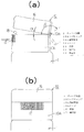
図1〜図3は、この発明に係る泡状物質噴出チューブ容器の実施例1を示す図面である。1は泡状物質噴出チューブ容器のチューブ容器であり、チューブ容器1の胴部1aは、圧搾及び弾性復元力が可能なように構成されている。そして、チューブ容器1の口部2には、漏斗状の泡発生装置3が装着されている。この泡発生装置3の開口端部3bの外周には、ディップチューブ5が嵌合され、このディップチューブ5は内流路6を構成している。図1は実施例1を倒立状態で使用している図面であり、チューブ容器1の胴部1aを押圧状態から解放すると、エアーバックすることにより、ラバー弁3cを開口して、外気流入路4から空気が流入する。そして、空気が内容液7内を通過する際に内容液7と混合し、その上部空間8で発泡して泡状物質を形成する。発泡した泡状物質は、ディップチューブ5の内流路6を通り、泡発生装置3に供給され外部に注出される。この実施例1は、口部2に通常のキャップが螺合されている(図示せず)。   1-3 is drawing which shows Example 1 of the foamy substance ejection tube container based on this invention. 1 is a tube container of a foam-like substance ejection tube container, and the trunk | drum 1a of the tube container 1 is comprised so that pressing and an elastic restoring force are possible. A funnel-shaped foam generating device 3 is attached to the mouth portion 2 of the tube container 1. A dip tube 5 is fitted to the outer periphery of the open end 3 b of the bubble generating device 3, and the dip tube 5 constitutes an inner flow path 6. FIG. 1 is a drawing in which the first embodiment is used in an inverted state. When the body portion 1a of the tube container 1 is released from the pressed state, the rubber valve 3c is opened by the air back, and the outside air inflow passage 4 is opened. Air flows in from. When air passes through the content liquid 7, it mixes with the content liquid 7 and foams in the upper space 8 to form a foamy substance. The foamed foamed substance passes through the inner flow path 6 of the dip tube 5 and is supplied to the foam generating device 3 and poured out to the outside. In the first embodiment, a normal cap is screwed into the mouth portion 2 (not shown).

実施例1は、泡発生装置3内に多孔性部材を設けないで、メッシュ5aをディップチューブ5の端部に設けたので、図7に示すように、従来、チューブ容器1を横にした場合、ディップチューブ5の内流路6内に内容液が入り込まない。そして、水溶液のまま、泡発生装置に供給されるのを防止できる。そのため、最初、噴出時又は再噴出時の際、泡発生装置から泡状の内容物が噴出される。又泡発生装置内に多孔性部材を設けた場合に比べ、泡状物質を噴出する際の押圧の抵抗感が少ない。又よりきめ細かい泡状物質を発生させることができる。さらに、メッシュ5aを使用することで、泡になり難い内容物であっても、より効果的に大きく発泡した泡状物質を作ることができる。メッシュ5aの材質としては、ポリエステル、ポリエチレン、ポリプロピレン、ナイロン等の合成樹脂が好ましい。メッシュの目開きは1〜500μが適し、50〜200μがより好ましい。   In Example 1, since the mesh 5a was provided at the end of the dip tube 5 without providing the porous member in the foam generating device 3, conventionally, as shown in FIG. The content liquid does not enter the inner flow path 6 of the dip tube 5. And it can prevent supplying with a foam generator with aqueous solution. Therefore, at the time of ejection or re-ejection, foam-like contents are ejected from the foam generating device. Moreover, compared with the case where a porous member is provided in the foam generator, there is less resistance to pressing when the foam material is ejected. In addition, finer foams can be generated. Furthermore, by using the mesh 5a, even if the content is difficult to be foamed, it is possible to make a foam material that is more effectively foamed. The material of the mesh 5a is preferably a synthetic resin such as polyester, polyethylene, polypropylene, or nylon. The mesh opening is preferably 1 to 500 μm, more preferably 50 to 200 μm.

次に、実施例1は、泡発生装置3の先端に鍔部9が形成されている。この鍔部9は、チューブ容器1がエアーバックする際に、泡発生装置3から注出した泡状物質を外気流入路4から吸い込まないように、遮断する機能を有する。外気流入路4から泡状物質が吸い込まれると、チューブ容器1のエアーバックが妨げられるからである。図1に示すように、鍔部9の突出寸法Tは、2mm≦T≦6mmが適し、3mm≦T≦5mmがより好ましい。   Next, in Example 1, a flange 9 is formed at the tip of the bubble generating device 3. The flange 9 has a function of blocking the foamed substance poured out from the foam generating device 3 from being sucked from the outside air inflow path 4 when the tube container 1 is air-backed. This is because air bubbles in the tube container 1 are hindered when the foamy substance is sucked from the outside air inflow path 4. As shown in FIG. 1, 2 mm ≦ T ≦ 6 mm is suitable for the projecting dimension T of the flange portion 9, and 3 mm ≦ T ≦ 5 mm is more preferable.

図3は、本発明の実施例2である。実施例2は、チューブ容器1の口部2に、ヒンジキャップ10が螺合されている実施例である。チューブ容器1の口部2には、ヒンジキャップ10の基幹筒体10aが螺合されている。ヒンジキャップ10は、基幹筒体10aの内側に形成され、雌ねじを有する内筒12と、この内筒12の天面に形成される頂壁13と、この頂壁13に形成される注出口14と、この注出口14に開閉自在に嵌合する嵌合筒15を下面に有する蓋体16とから構成されている。そして、図4(a)(b)に示すように、この基幹筒体10aの正面には、弾片部17が形成されており、この弾片部17に連続して係合片18が形成されている。一方蓋体16には、係合片18と係脱自在に係合する係合片19と、蓋体16を一定の角度αだけ開くための断面三角片21が形成され、一端がヒンジ10bによって基幹筒体10aと連結されている。このヒンジ10bは、実施例2では引張帯付のヒンジが用いられている。   FIG. 3 is a second embodiment of the present invention. The second embodiment is an embodiment in which a hinge cap 10 is screwed into the mouth portion 2 of the tube container 1. A trunk cylinder 10 a of a hinge cap 10 is screwed into the mouth portion 2 of the tube container 1. The hinge cap 10 is formed on the inner side of the trunk cylinder 10 a, and has an inner cylinder 12 having an internal thread, a top wall 13 formed on the top surface of the inner cylinder 12, and a spout 14 formed on the top wall 13. And a lid 16 having a fitting cylinder 15 fitted to the spout 14 so as to be opened and closed. 4 (a) and 4 (b), a bullet piece portion 17 is formed on the front surface of the trunk cylinder 10a, and an engagement piece 18 is formed continuously with the bullet piece portion 17. Has been. On the other hand, the lid body 16 is formed with an engagement piece 19 that is detachably engaged with the engagement piece 18 and a triangular cross-section piece 21 for opening the lid body 16 by a certain angle α, and one end is formed by a hinge 10b. It is connected to the trunk cylinder 10a. As the hinge 10b, a hinge with a tension band is used in the second embodiment.

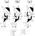
図5は、ヒンジキャップ10の蓋体16が、基幹筒体10aの操作により、一定角αだけ開く状態を示す図面である。図5(a)は、蓋体16が基幹筒体10aに嵌合している状態を示す図面である。すなわち、基幹筒体10aの係合片18の頭部18aと、蓋体16の係合片19の頭部19aが係合している状態を示している。図5(b)は、弾性部17を少し押圧し、係合片18の頭部18aと、係合片19の頭部19aの係合が外れる状態を示した図面である。図5(c)は、弾性部17をさらに押圧し、係合片18の頭部18aが、蓋体16の断面三角片21の斜面部を滑ることにより、蓋体16を上方に押し上げる状態を示した図面である。これにより、注出口14と嵌合筒15は嵌合が解除され、注出口14は開放され泡状物質が注出できる。図4に示すように、一定角αまで蓋体16が開いた後、親指で蓋体16を持ち上げると、蓋体16は、引張帯付ヒンジ10bの作用により、自動的に120度以上開く。すなわち、ワンタッチ操作で開くことができる。蓋体16を閉める場合は、蓋体16を手で押圧すると、係合片18の頭部18aと、蓋体16の係合片19の頭部19aがクリック感を生じて係合し、蓋体16は基幹筒体10aと係合すると同時に、注出口14と嵌合筒15は嵌合し、注出口14は閉鎖される。   FIG. 5 is a view showing a state in which the lid 16 of the hinge cap 10 is opened by a certain angle α by the operation of the trunk cylinder 10a. FIG. 5A is a view showing a state in which the lid body 16 is fitted to the trunk cylinder body 10a. That is, the head 18a of the engagement piece 18 of the trunk cylinder 10a and the head 19a of the engagement piece 19 of the lid 16 are engaged. FIG. 5B is a diagram showing a state in which the elastic portion 17 is slightly pressed to disengage the head 18 a of the engagement piece 18 and the head 19 a of the engagement piece 19. 5C shows a state in which the elastic portion 17 is further pressed, and the head portion 18a of the engagement piece 18 slides on the slope portion of the cross-sectional triangular piece 21 of the lid body 16 to push the lid body 16 upward. FIG. Thereby, the spout 14 and the fitting cylinder 15 are disengaged, the spout 14 is opened, and the foamy substance can be poured out. As shown in FIG. 4, when the lid 16 is lifted with the thumb after the lid 16 is opened to a certain angle α, the lid 16 is automatically opened by 120 degrees or more by the action of the hinge 10 b with the tension band. That is, it can be opened by a one-touch operation. When closing the lid body 16, when the lid body 16 is pressed by hand, the head portion 18a of the engagement piece 18 and the head portion 19a of the engagement piece 19 of the lid body 16 are engaged with each other with a click feeling. At the same time that the body 16 engages with the trunk cylinder 10a, the spout 14 and the fitting cylinder 15 are fitted, and the spout 14 is closed.

チューブ容器1から泡状物質を注出する場合は、ヒンジキャップ10の蓋体16を、基幹筒体10aから外し、基幹筒体10aの注出口14を開口し、倒立状態でチューブ容器1の胴部1aを押圧すると、メッシュ5aによって発泡された内容物が、発泡した状態でディップチューブ5の内流路6を通過して泡発生装置3内に送られ、注出口14から外部に注出される。チューブ容器1内に、空気がなくなり減圧化した場合、ラバー弁3cが開口し、外気は、外気流入路4を通りチューブ容器1内に流入する。これによりチューブ容器1の内部には外気が流入し、内容物と空気が混合し発泡する。そして再度押圧可能となる。なお、口部2と泡発生装置3との嵌合が堅固であり、又外気流入路4は、ラバー弁3cにより密閉されているため、通常の状態で内容物が口部2から漏洩することがない。そして、従来、泡発生装置から水溶液状の内容物が注出されるという欠点があったが、ディップチューブ55の内流路56内に溜まった空気又は泡状物質と内容液が接したとき、両者が置換しない。したがって、水溶液のまま、最初の噴出時及び再噴出時の際、泡発生装置から水溶液状の内容物が抽出されるという欠点は解消される。   When the foamy substance is to be poured out from the tube container 1, the lid 16 of the hinge cap 10 is removed from the trunk cylinder 10a, the spout 14 of the trunk cylinder 10a is opened, and the tube container 1 is in an inverted state. When the portion 1a is pressed, the content foamed by the mesh 5a passes through the inner flow path 6 of the dip tube 5 in the foamed state, is sent into the foam generating device 3, and is poured out from the spout 14 to the outside. . When there is no air in the tube container 1 and the pressure is reduced, the rubber valve 3c is opened and the outside air flows into the tube container 1 through the outside air inflow path 4. As a result, outside air flows into the tube container 1, and the contents and air are mixed and foamed. And it becomes possible to press again. In addition, since the fitting of the mouth part 2 and the foam generating device 3 is firm and the outside air inflow path 4 is sealed by the rubber valve 3c, the contents leak from the mouth part 2 in a normal state. There is no. Conventionally, there has been a drawback that the content in the form of an aqueous solution is poured out from the foam generating device, but when the air or the foamy substance accumulated in the inner flow path 56 of the dip tube 55 comes into contact with the content liquid, Does not replace. Therefore, the disadvantage that the aqueous solution-like contents are extracted from the bubble generating device at the time of the first ejection and the re-ejection with the aqueous solution is eliminated.

図6〜図8は、本発明の実施例3である。この実施例に係る容器は、チューブ容器31と、ヒンジキャップ40と、ディップチューブ35とを備えている。ヒンジキャップ40は、基幹筒体40aと、基幹筒体40aとヒンジ40bを介して連結された蓋体46とを備えている。この基幹筒体40aは、外筒41と、外筒の内側に形成された雌ねじを有する内筒42とを備え、内筒42がチューブ容器31の口部32に螺合される。この内筒42は、その天面に注出口44a及び外気流入筒44bを備えた頂壁43を有している。これら注出口44aと外気流入筒44bは、実施例1と異なり、同心円状に設けられていない。さらに、注出口44aは、その上端が外気流入筒44bの上端よりも高く形成されており、又その位置が外気流入筒44bの位置よりも基幹筒体40a(外筒41)の外周寄りに形成されている。一方、外筒41には、実施例2(図3〜図5)と同様に、蓋体46をワンタッチで開く機構を設けることができる。また、蓋体46は、閉蓋状態において、注出口44a及び外気流入筒44bを密閉する嵌合筒45a、45bを備えている。   6 to 8 show a third embodiment of the present invention. The container according to this embodiment includes a tube container 31, a hinge cap 40, and a dip tube 35. The hinge cap 40 includes a trunk cylinder 40a and a lid 46 connected to the trunk cylinder 40a and the hinge 40b. The trunk cylinder 40 a includes an outer cylinder 41 and an inner cylinder 42 having an internal thread formed inside the outer cylinder, and the inner cylinder 42 is screwed into the mouth portion 32 of the tube container 31. The inner cylinder 42 has a top wall 43 provided with a spout 44a and an outside air inflow cylinder 44b on its top surface. Unlike the first embodiment, the spout 44a and the outside air inflow cylinder 44b are not provided concentrically. Further, the spout 44a is formed such that its upper end is higher than the upper end of the outside air inflow cylinder 44b, and its position is formed closer to the outer periphery of the main cylinder 40a (outer cylinder 41) than the position of the outside air inflow cylinder 44b. Has been. On the other hand, similarly to the second embodiment (FIGS. 3 to 5), the outer cylinder 41 can be provided with a mechanism for opening the lid 46 with one touch. The lid body 46 includes fitting cylinders 45a and 45b that seal the spout 44a and the outside air inflow cylinder 44b in the closed state.

このように構成されたヒンジキャップ40には、内流路36を構成するディップチューブ35が頂壁43の裏面に接続され、注出口44aに連通している。このディップチューブ35の下端には、実施例1と同様のメッシュ35aが設けられている。また、外気流入筒44b内には球状弁44cが挿入されているのが好ましい。この球状弁44cは、後述するように、開口が狭くされた上部弁座44dと複数の突起で構成された下部弁座44eとの間を移動可能にされている。このように構成することで、全体の部品点数を減らすことができると共に、実施例1のラバー弁3cよりも安価な球状弁44cによって、製造コストをより一層低く抑えることができる。   In the hinge cap 40 thus configured, the dip tube 35 constituting the inner flow path 36 is connected to the back surface of the top wall 43 and communicates with the spout 44a. At the lower end of the dip tube 35, a mesh 35a similar to that of the first embodiment is provided. A spherical valve 44c is preferably inserted into the outside air inflow cylinder 44b. As will be described later, the spherical valve 44c is movable between an upper valve seat 44d having a narrow opening and a lower valve seat 44e constituted by a plurality of protrusions. With this configuration, the total number of parts can be reduced, and the manufacturing cost can be further reduced by the spherical valve 44c that is cheaper than the rubber valve 3c of the first embodiment.

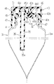
次に、チューブ容器31から泡状物質を注出する方法について説明する。まず、ヒンジキャップ40の蓋体46を実施例2と同様に開放し(図5)、注出口44a及び外気流入筒44bを開口させる。そして、図7のようにチューブ容器31を倒立状態にして、チューブ容器31の胴部31aを押圧する。そうすると、メッシュ35aによってきめ細かく発泡された内容物が、矢印で示すように、ディップチューブ35の内流路36を通って注出口44aから注出される。このとき、水溶液状の内容物が注出されてしまうのを効果的に防ぐことができる。一方、外気流入筒44bは、上部弁座44dに当接した球状弁44cによって塞がれているため、内容液37が外気流入筒44bから漏れ出すことはない。   Next, a method for extracting the foamy substance from the tube container 31 will be described. First, the lid 46 of the hinge cap 40 is opened as in the second embodiment (FIG. 5), and the spout 44a and the outside air inflow tube 44b are opened. Then, the tube container 31 is turned upside down as shown in FIG. Then, the content finely foamed by the mesh 35a is poured out from the spout 44a through the inner flow path 36 of the dip tube 35, as indicated by an arrow. At this time, it is possible to effectively prevent the aqueous content from being poured out. On the other hand, since the outside air inflow cylinder 44b is closed by the spherical valve 44c that is in contact with the upper valve seat 44d, the content liquid 37 does not leak from the outside air inflow cylinder 44b.

そして、胴部31aの押圧をやめると、図8のようにエアーバック現象が生じる。すなわち、上部弁座44dに当接していた球状弁44cが下部弁座44e側に移動することにより、外気が、矢印で示すように外気流入筒44bを通ってチューブ容器31内に流入する。このエアーバック現象によって、チューブ容器31の胴部31aが復元すると共に、チューブ容器31内の内容液37が空気と混合し、容器の上部空間38に泡状物質を形成する。そして、チューブ容器31の胴部31aを再び押圧することができる。   Then, when the pressing of the body portion 31a is stopped, an air bag phenomenon occurs as shown in FIG. That is, when the spherical valve 44c that has been in contact with the upper valve seat 44d moves toward the lower valve seat 44e, the outside air flows into the tube container 31 through the outside air inflow cylinder 44b as indicated by an arrow. Due to this air bag phenomenon, the body portion 31a of the tube container 31 is restored, and the content liquid 37 in the tube container 31 is mixed with air to form a foamy substance in the upper space 38 of the container. And the trunk | drum 31a of the tube container 31 can be pressed again.

一方、エアーバック現象が生じると、注出後の泡状物質を外気流入筒44bへ引き込む力が作用する。もし泡状物質が外気流入筒44bに付着し、後に乾燥、固化するようなことがあると、チューブ容器31内へ外気を流入させることができなくなる虞がある。しかしながら、本実施例では、注出口44aの上端が外気流入筒44bよりも高く形成されており、しかもこれらが同心円状に設けられていないため、そのような不具合を防ぐことができる。   On the other hand, when the air bag phenomenon occurs, a force for drawing the foamed substance after the pouring into the outside air inflow cylinder 44b acts. If the foamy substance adheres to the outside air inflow cylinder 44b and is dried or solidified later, the outside air may not be allowed to flow into the tube container 31. However, in this embodiment, since the upper end of the spout 44a is formed higher than the outside air inflow cylinder 44b, and these are not provided concentrically, such a problem can be prevented.

また、本発明に係る泡状物質噴出チューブ容器は、チューブ容器1、31の容積を小さくすることで、バック等の中に入れて持ち運びができる。携帯用チューブとして、バックに入れて持ち歩く場合には、チューブ容器1、31の丈寸法は、59mm≦A≦182mm、好ましくは72mm≦A≦164mmである。又チューブ容器1、31の胴部1a、31aの外径寸法は、19mm≦B≦40mm、好ましくは25mm≦B≦35mmである。もちろん、チューブ容器1、31の丈、外径を大きくすることにより、一般家庭用、一般業務用として用いることもできる。   Moreover, the foam material ejection tube container according to the present invention can be carried in a bag or the like by reducing the volume of the tube containers 1 and 31. When carrying as a portable tube in a bag, the length dimensions of the tube containers 1 and 31 are 59 mm ≦ A ≦ 182 mm, preferably 72 mm ≦ A ≦ 164 mm. The outer diameter dimensions of the body portions 1a and 31a of the tube containers 1 and 31 are 19 mm ≦ B ≦ 40 mm, preferably 25 mm ≦ B ≦ 35 mm. Of course, by increasing the length and outer diameter of the tube containers 1 and 31, they can be used for general household use and general business use.

以上、本発明の実施の形態を説明してきたが、本発明はこれら実施の形態に限定されるものではない。例えば、上述の実施の形態では、メッシュ5a、35aが、ディップチューブ5、35の端部に直接設けられているが、別途用意した部材、例えば筒状部材に1つ又は複数のメッシュを設け、この部材をディップチューブの端部に嵌合させたものであってもよい(図示せず)。また、メッシュ5a、35aに限らず、合成樹脂等の発泡体や焼結体、あるいは不織布のような多孔質部材であってもよく、これら多孔質部材とメッシュを組み合わせたものであってもよい(図示せず)。さらに、本発明の実施の形態では、チューブ容器1、31を例に挙げて説明してきたが、チューブ容器に代えて、弾性復元力を有するボトル容器とした場合にも本発明と同様の効果を得ることができる(図示せず)。   As mentioned above, although embodiment of this invention has been described, this invention is not limited to these embodiment. For example, in the above-described embodiment, the meshes 5a and 35a are directly provided at the ends of the dip tubes 5 and 35, but one or more meshes are provided on a separately prepared member, for example, a cylindrical member, This member may be fitted to the end of the dip tube (not shown). Moreover, it is not limited to the meshes 5a and 35a, and may be a porous member such as a foamed body such as a synthetic resin, a sintered body, or a nonwoven fabric, or may be a combination of these porous member and mesh. (Not shown). Furthermore, in the embodiment of the present invention, the tube containers 1 and 31 have been described as examples. However, the same effect as in the present invention can be obtained when a bottle container having an elastic restoring force is used instead of the tube container. Can be obtained (not shown).

本発明に係る泡状物質噴出チューブ容器は、消毒液等の薬剤、ヘアークリーム等の化粧品、シェービングクリーム、ハンドソープ等のビューティケア製品又は食品等を充填して、使用時に、初めから確実に泡状物質を注出できるので、泡状物質噴出チューブ容器として、広く利用することができる。特にチューブ容器のサイズを小さくすることで、バッグ等の中に携帯用として持ち運びが便利である。さらに一般家庭、会社等で使用されてもよく、一般家庭、会社等の洗面場に常時載置されてもよい。   The foam material ejection tube container according to the present invention is filled with a medicine such as a disinfectant, cosmetics such as hair cream, beauty care products such as shaving cream and hand soap, foods, etc. Since a foam-like substance can be poured out, it can be widely used as a foam-like substance ejection tube container. In particular, by reducing the size of the tube container, it is convenient to carry it in a bag or the like for portable use. Further, it may be used in ordinary households, companies, etc., and may be always placed in a washroom of ordinary households, companies, etc.

1,31 チューブ容器
2,32 口部
3 泡発生装置
4 外気流入路
5,35 ディップチューブ
5a,35a メッシュ
6,36 内流路
9 鍔部
10,40 ヒンジキャップ
10a,40a 基幹筒体
10b,40b ヒンジ
11,41 外筒
12,42 内筒
14,44a 注出口
15,45a,45b 嵌合筒
16,46 蓋体
17,47 弾片部
18,19,48,49 係合片
21,51 三角片
44b 外気流入筒
44c 球状弁
44d 上部弁座
44e 下部弁座
DESCRIPTION OF SYMBOLS 1,31 Tube container 2,32 Mouth part 3 Foam generator 4 Outside air inflow path 5,35 Dip tube 5a, 35a Mesh 6,36 Inner flow path 9 Gutter part 10,40 Hinge cap 10a, 40a Base cylinder 10b, 40b Hinge 11, 41 Outer cylinder 12, 42 Inner cylinder 14, 44 a Spout 15, 45 a, 45 b Fitting cylinder 16, 46 Lid 17, 47 Elastic piece 18, 19, 48, 49 Engagement piece 21, 51 Triangular piece 44b Outside air inflow cylinder 44c Spherical valve 44d Upper valve seat 44e Lower valve seat

Claims (10)

弾性復元力を有するチューブ容器の口部に、開口端部の外周面にディップチューブが嵌合された泡発生装置が装着され、ディップチューブにメッシュが設けられると共に外気流入路を形成し、ディップチューブを介して、メッシュとチューブ容器内とを連通する、内流路を設けたことを特徴とする泡状物質噴出チューブ容器。   A foam generating device in which a dip tube is fitted to the outer peripheral surface of the opening end portion is attached to the mouth portion of the tube container having elastic restoring force, and the dip tube is provided with a mesh and forms an outside air inflow path. A foam-like substance ejection tube container comprising an inner flow path for communicating the mesh and the inside of the tube container via 泡発生装置の先端に、鍔部を形成することを特徴とする請求項1記載の泡状物質噴出チューブ容器。   The foamed substance ejection tube container according to claim 1, wherein a flange is formed at the tip of the foam generating device. 泡状物質噴出チューブ容器の口部に、ヒンジキャップが螺合又は嵌合されることを特徴とする請求項1又は2記載の泡状物質噴出チューブ容器。   The foamed substance ejection tube container according to claim 1 or 2, wherein a hinge cap is screwed or fitted into the mouth of the foamed substance ejection tube container. 前記ヒンジキャップは、チューブ容器の口部に装着される基幹筒体と、該基幹筒体とヒンジを介して連結される蓋体からなり、(a)基幹筒体は、蓋体を開けるために押圧操作されうる弾片部及び係止片を有する外筒と、外筒の内側に形成され、チューブ容器の口部に螺合又は嵌合される内筒と、内筒の天面に形成され泡状物質を噴出する注出口とからなり、(b)蓋体は、外筒の係止片と係脱自在に係合する係止片及び蓋体を一定角度押し上げる三角片を有し、嵌合筒が基幹筒体の注出口に係脱自在に係合することを特徴とする請求項3記載の泡状物質墳出チューブ容器。   The hinge cap is composed of a trunk cylinder attached to the mouth of the tube container and a lid connected to the trunk cylinder via a hinge. (A) The trunk cylinder is for opening the lid. An outer cylinder having an elastic piece portion and a locking piece that can be pressed, an inner cylinder formed inside the outer cylinder and screwed or fitted into the mouth of the tube container, and formed on the top surface of the inner cylinder. (B) The lid body has a locking piece that detachably engages with the locking piece of the outer cylinder and a triangular piece that pushes up the lid body at a certain angle. 4. The foamed material extraction tube container according to claim 3, wherein the joint tube is detachably engaged with the spout of the basic cylinder. 弾性復元力を有するチューブ容器と、該チューブ容器の口部に装着されるヒンジキャップとを備え、
該ヒンジキャップには、チューブ容器内に外気を取り込む外気流入筒と泡状物質を噴出する注出口とが形成され、かつ該注出口に連通するディップチューブが接続されており、
該ディップチューブにメッシュが設けられ、ディップチューブを介して、メッシュとチューブ容器内とを連通する内流路を設けたことを特徴とする泡状物質墳出チューブ容器。
A tube container having an elastic restoring force, and a hinge cap attached to the mouth of the tube container;
The hinge cap is formed with an outside air inflow cylinder for taking outside air into the tube container and a spout for ejecting foamy substance, and a dip tube connected to the spout is connected to the hinge cap,
A foamed substance extraction tube container, wherein the dip tube is provided with a mesh, and an internal flow path is provided to communicate the mesh and the inside of the tube container via the dip tube.
前記注出口の上端が、外気流入筒の上端よりも高く形成されている請求項5記載の泡状物質墳出チューブ容器。   The foamed material extraction tube container according to claim 5, wherein an upper end of the spout is formed higher than an upper end of the outside air inflow cylinder. 前記外気流入筒内に球状弁が挿入された請求項5又は6記載の泡状物質墳出チューブ容器。   The foamed substance extraction tube container according to claim 5 or 6, wherein a spherical valve is inserted into the outside air inflow cylinder. 前記ヒンジキャップは、チューブ容器の口部に装着される基幹筒体と、該基幹筒体とヒンジを介して連結される蓋体からなり、(a)基幹筒体は、蓋体を開けるために押圧操作されうる弾片部及び係止片を有する外筒と、外筒の内側に形成され、チューブ容器の口部に螺合又は嵌合される内筒と、内筒の天面に形成された前記注出口と外気流入筒とからなり、(b)蓋体は、外筒の係止片と係脱自在に係合する係止片及び蓋体を一定角度押し上げる三角片を有し、嵌合筒が前記基幹筒体の注出口及び外気流入筒に係脱自在に係合する請求項5〜7記載の泡状物質墳出チューブ容器。   The hinge cap is composed of a trunk cylinder attached to the mouth of the tube container and a lid connected to the trunk cylinder via a hinge. (A) The trunk cylinder is for opening the lid. An outer cylinder having an elastic piece portion and a locking piece that can be pressed, an inner cylinder formed inside the outer cylinder and screwed or fitted into the mouth of the tube container, and formed on the top surface of the inner cylinder. (B) the lid has a locking piece that is detachably engaged with the locking piece of the outer cylinder and a triangular piece that pushes up the lid at a certain angle, and is fitted. The foamed substance discharge tube container according to claim 5, wherein the joint cylinder is detachably engaged with the spout and the outside air inflow cylinder of the basic cylinder. 前記メッシュに代えて、発泡体、焼結体、不織布のいずれかからなる多孔質部材とした請求項1〜8記載の泡状物質墳出チューブ容器。   The foamed material extraction tube container according to claim 1, wherein a porous member made of any one of a foam, a sintered body, and a nonwoven fabric is used in place of the mesh. 前記チューブ容器に代えて、ボトル容器とした請求項1〜9記載の泡状物質噴出チューブ容器。   The foam material ejection tube container according to claim 1, wherein a bottle container is used instead of the tube container.
JP2011253984A 2011-01-12 2011-11-21 Bubble-like substance jetting tube vessel Pending JP2012158391A (en)

Priority Applications (1)

Application Number Priority Date Filing Date Title
JP2011253984A JP2012158391A (en) 2011-01-12 2011-11-21 Bubble-like substance jetting tube vessel

Applications Claiming Priority (3)

Application Number Priority Date Filing Date Title
JP2011003709 2011-01-12
JP2011253984A JP2012158391A (en) 2011-01-12 2011-11-21 Bubble-like substance jetting tube vessel

Publications (1)

Publication Number Publication Date
JP2012158391A true JP2012158391A (en) 2012-08-23

Family

ID=46839260

Family Applications (1)

Application Number Title Priority Date Filing Date
JP2011253984A Pending JP2012158391A (en) 2011-01-12 2011-11-21 Bubble-like substance jetting tube vessel

Country Status (1)

Country Link
JP (1) JP2012158391A (en)

Cited By (6)

* Cited by examiner, † Cited by third party
Publication number Priority date Publication date Assignee Title
JP2014136580A (en) * 2013-01-15 2014-07-28 Takeuchi Yoki Kk Foam discharge container
WO2015099338A1 (en) * 2013-12-26 2015-07-02 (주)연우 Foam jetting tube container
KR101737866B1 (en) 2015-09-30 2017-05-19 (주)연우 Tube vessel for bubble spouting
JP2017132531A (en) * 2016-01-29 2017-08-03 株式会社吉野工業所 Pouring-out container
JP2017178446A (en) * 2016-03-31 2017-10-05 株式会社吉野工業所 Foam discharge container
JP2019081575A (en) * 2017-10-30 2019-05-30 株式会社吉野工業所 Foam discharge container

Citations (8)

* Cited by examiner, † Cited by third party
Publication number Priority date Publication date Assignee Title
JPS5346952U (en) * 1976-09-21 1978-04-21
JPS61183159U (en) * 1985-05-01 1986-11-15
JPH1029652A (en) * 1996-05-14 1998-02-03 Kao Corp Foam dispense container
JPH11106795A (en) * 1997-10-01 1999-04-20 Lion Corp Detergent contained in container equipped with foam-forming mechanism
JP2003515443A (en) * 1999-12-02 2003-05-07 タプラスト ソチエタ ペル アツィオニ Method of injecting liquid in foam form by a deformable container and apparatus using the method
JP2007008553A (en) * 2005-07-01 2007-01-18 Taisho Pharm Ind Ltd Container cap
JP2007119024A (en) * 2005-10-31 2007-05-17 Procter & Gamble Co Liquid spout cap
JP2009154885A (en) * 2007-12-25 2009-07-16 Kao Corp Squeeze type foam delivering container

Patent Citations (8)

* Cited by examiner, † Cited by third party
Publication number Priority date Publication date Assignee Title
JPS5346952U (en) * 1976-09-21 1978-04-21
JPS61183159U (en) * 1985-05-01 1986-11-15
JPH1029652A (en) * 1996-05-14 1998-02-03 Kao Corp Foam dispense container
JPH11106795A (en) * 1997-10-01 1999-04-20 Lion Corp Detergent contained in container equipped with foam-forming mechanism
JP2003515443A (en) * 1999-12-02 2003-05-07 タプラスト ソチエタ ペル アツィオニ Method of injecting liquid in foam form by a deformable container and apparatus using the method
JP2007008553A (en) * 2005-07-01 2007-01-18 Taisho Pharm Ind Ltd Container cap
JP2007119024A (en) * 2005-10-31 2007-05-17 Procter & Gamble Co Liquid spout cap
JP2009154885A (en) * 2007-12-25 2009-07-16 Kao Corp Squeeze type foam delivering container

Cited By (8)

* Cited by examiner, † Cited by third party
Publication number Priority date Publication date Assignee Title
JP2014136580A (en) * 2013-01-15 2014-07-28 Takeuchi Yoki Kk Foam discharge container
WO2015099338A1 (en) * 2013-12-26 2015-07-02 (주)연우 Foam jetting tube container
CN105873832A (en) * 2013-12-26 2016-08-17 衍宇株式会社 Foam jetting tube container
KR101737866B1 (en) 2015-09-30 2017-05-19 (주)연우 Tube vessel for bubble spouting
JP2017132531A (en) * 2016-01-29 2017-08-03 株式会社吉野工業所 Pouring-out container
JP2017178446A (en) * 2016-03-31 2017-10-05 株式会社吉野工業所 Foam discharge container
JP2019081575A (en) * 2017-10-30 2019-05-30 株式会社吉野工業所 Foam discharge container
JP7025890B2 (en) 2017-10-30 2022-02-25 株式会社吉野工業所 Foam ejection container

Similar Documents

Publication Publication Date Title
US8261943B2 (en) Spray bottle with refill cartridge
JP2012158391A (en) Bubble-like substance jetting tube vessel
JP6636843B2 (en) Foam spouting container
RU2013109379A (en) CAPACITIES AND METHODS OF MIXING AND DOSED DISPENSION OF BEVERAGE CONCENTRATES
JP2016529169A5 (en)
US20190031401A1 (en) Dispensing systems and methods for using the same
JP2011098777A (en) Jet tube container for foamy substance
TW200826888A (en) Foaming device for generating skincare or cleaning foam
JP2018532659A (en) Foam spout tube container
JP5977642B2 (en) Refill container stopper
JP4917002B2 (en) Foam ejection container
JP6359407B2 (en) Discharge container
JP2014080239A (en) Refill type discharge container
JP6786163B2 (en) Squeeze former container
JP6644431B2 (en) Discharge container
JP2016141428A (en) Squeeze foamer container
JP5504701B2 (en) Foam discharge container
JP2016088563A (en) Foam jetting container
JP6552205B2 (en) Foam ejection container
WO2016158763A1 (en) Squeeze container
JP6012947B2 (en) Foam ejection container
JP6416043B2 (en) Foam ejection container
KR101961228B1 (en) Multi-cap discharging liquid by spray method or combined method
JP2012106749A (en) Content filling mechanism
JP7025890B2 (en) Foam ejection container

Legal Events

Date Code Title Description
A621 Written request for application examination

Free format text: JAPANESE INTERMEDIATE CODE: A621

Effective date: 20141114

A977 Report on retrieval

Free format text: JAPANESE INTERMEDIATE CODE: A971007

Effective date: 20150813

A131 Notification of reasons for refusal

Free format text: JAPANESE INTERMEDIATE CODE: A131

Effective date: 20150825

A02 Decision of refusal

Free format text: JAPANESE INTERMEDIATE CODE: A02

Effective date: 20151222