EP3357779A1 - Vehicle control device - Google Patents
Vehicle control device Download PDFInfo
- Publication number
- EP3357779A1 EP3357779A1 EP16850900.8A EP16850900A EP3357779A1 EP 3357779 A1 EP3357779 A1 EP 3357779A1 EP 16850900 A EP16850900 A EP 16850900A EP 3357779 A1 EP3357779 A1 EP 3357779A1
- Authority
- EP
- European Patent Office
- Prior art keywords
- vehicle
- deceleration
- control device
- required deceleration
- brake
- Prior art date
- Legal status (The legal status is an assumption and is not a legal conclusion. Google has not performed a legal analysis and makes no representation as to the accuracy of the status listed.)
- Granted
Links
- 230000005540 biological transmission Effects 0.000 claims abstract description 120
- 230000007246 mechanism Effects 0.000 claims abstract description 89
- 239000000446 fuel Substances 0.000 claims abstract description 23
- 230000007423 decrease Effects 0.000 claims description 2
- 238000000034 method Methods 0.000 description 23
- 230000008569 process Effects 0.000 description 20
- 238000010586 diagram Methods 0.000 description 16
- 239000007858 starting material Substances 0.000 description 7
- 230000001133 acceleration Effects 0.000 description 4
- 230000008859 change Effects 0.000 description 4
- 238000003825 pressing Methods 0.000 description 3
- 238000004891 communication Methods 0.000 description 2
- 230000015556 catabolic process Effects 0.000 description 1
- 238000006243 chemical reaction Methods 0.000 description 1
- 239000003638 chemical reducing agent Substances 0.000 description 1
- 238000006731 degradation reaction Methods 0.000 description 1
- 230000001419 dependent effect Effects 0.000 description 1
- 230000000694 effects Effects 0.000 description 1
- 230000006872 improvement Effects 0.000 description 1
- 238000013021 overheating Methods 0.000 description 1
- 238000010248 power generation Methods 0.000 description 1
- 230000004044 response Effects 0.000 description 1
- 238000005096 rolling process Methods 0.000 description 1
- 230000035939 shock Effects 0.000 description 1
Images


Classifications
-
- B—PERFORMING OPERATIONS; TRANSPORTING
- B60—VEHICLES IN GENERAL
- B60W—CONJOINT CONTROL OF VEHICLE SUB-UNITS OF DIFFERENT TYPE OR DIFFERENT FUNCTION; CONTROL SYSTEMS SPECIALLY ADAPTED FOR HYBRID VEHICLES; ROAD VEHICLE DRIVE CONTROL SYSTEMS FOR PURPOSES NOT RELATED TO THE CONTROL OF A PARTICULAR SUB-UNIT
- B60W30/00—Purposes of road vehicle drive control systems not related to the control of a particular sub-unit, e.g. of systems using conjoint control of vehicle sub-units, or advanced driver assistance systems for ensuring comfort, stability and safety or drive control systems for propelling or retarding the vehicle
- B60W30/18—Propelling the vehicle
- B60W30/182—Selecting between different operative modes, e.g. comfort and performance modes
-
- B—PERFORMING OPERATIONS; TRANSPORTING
- B60—VEHICLES IN GENERAL
- B60W—CONJOINT CONTROL OF VEHICLE SUB-UNITS OF DIFFERENT TYPE OR DIFFERENT FUNCTION; CONTROL SYSTEMS SPECIALLY ADAPTED FOR HYBRID VEHICLES; ROAD VEHICLE DRIVE CONTROL SYSTEMS FOR PURPOSES NOT RELATED TO THE CONTROL OF A PARTICULAR SUB-UNIT
- B60W10/00—Conjoint control of vehicle sub-units of different type or different function
- B60W10/02—Conjoint control of vehicle sub-units of different type or different function including control of driveline clutches
-
- B—PERFORMING OPERATIONS; TRANSPORTING
- B60—VEHICLES IN GENERAL
- B60W—CONJOINT CONTROL OF VEHICLE SUB-UNITS OF DIFFERENT TYPE OR DIFFERENT FUNCTION; CONTROL SYSTEMS SPECIALLY ADAPTED FOR HYBRID VEHICLES; ROAD VEHICLE DRIVE CONTROL SYSTEMS FOR PURPOSES NOT RELATED TO THE CONTROL OF A PARTICULAR SUB-UNIT
- B60W10/00—Conjoint control of vehicle sub-units of different type or different function
- B60W10/04—Conjoint control of vehicle sub-units of different type or different function including control of propulsion units
- B60W10/06—Conjoint control of vehicle sub-units of different type or different function including control of propulsion units including control of combustion engines
-
- B—PERFORMING OPERATIONS; TRANSPORTING
- B60—VEHICLES IN GENERAL
- B60W—CONJOINT CONTROL OF VEHICLE SUB-UNITS OF DIFFERENT TYPE OR DIFFERENT FUNCTION; CONTROL SYSTEMS SPECIALLY ADAPTED FOR HYBRID VEHICLES; ROAD VEHICLE DRIVE CONTROL SYSTEMS FOR PURPOSES NOT RELATED TO THE CONTROL OF A PARTICULAR SUB-UNIT
- B60W10/00—Conjoint control of vehicle sub-units of different type or different function
- B60W10/10—Conjoint control of vehicle sub-units of different type or different function including control of change-speed gearings
- B60W10/101—Infinitely variable gearings
-
- B—PERFORMING OPERATIONS; TRANSPORTING
- B60—VEHICLES IN GENERAL
- B60W—CONJOINT CONTROL OF VEHICLE SUB-UNITS OF DIFFERENT TYPE OR DIFFERENT FUNCTION; CONTROL SYSTEMS SPECIALLY ADAPTED FOR HYBRID VEHICLES; ROAD VEHICLE DRIVE CONTROL SYSTEMS FOR PURPOSES NOT RELATED TO THE CONTROL OF A PARTICULAR SUB-UNIT
- B60W10/00—Conjoint control of vehicle sub-units of different type or different function
- B60W10/10—Conjoint control of vehicle sub-units of different type or different function including control of change-speed gearings
- B60W10/11—Stepped gearings
-
- B—PERFORMING OPERATIONS; TRANSPORTING
- B60—VEHICLES IN GENERAL
- B60W—CONJOINT CONTROL OF VEHICLE SUB-UNITS OF DIFFERENT TYPE OR DIFFERENT FUNCTION; CONTROL SYSTEMS SPECIALLY ADAPTED FOR HYBRID VEHICLES; ROAD VEHICLE DRIVE CONTROL SYSTEMS FOR PURPOSES NOT RELATED TO THE CONTROL OF A PARTICULAR SUB-UNIT
- B60W10/00—Conjoint control of vehicle sub-units of different type or different function
- B60W10/18—Conjoint control of vehicle sub-units of different type or different function including control of braking systems
- B60W10/184—Conjoint control of vehicle sub-units of different type or different function including control of braking systems with wheel brakes
-
- B—PERFORMING OPERATIONS; TRANSPORTING
- B60—VEHICLES IN GENERAL
- B60W—CONJOINT CONTROL OF VEHICLE SUB-UNITS OF DIFFERENT TYPE OR DIFFERENT FUNCTION; CONTROL SYSTEMS SPECIALLY ADAPTED FOR HYBRID VEHICLES; ROAD VEHICLE DRIVE CONTROL SYSTEMS FOR PURPOSES NOT RELATED TO THE CONTROL OF A PARTICULAR SUB-UNIT
- B60W30/00—Purposes of road vehicle drive control systems not related to the control of a particular sub-unit, e.g. of systems using conjoint control of vehicle sub-units, or advanced driver assistance systems for ensuring comfort, stability and safety or drive control systems for propelling or retarding the vehicle
- B60W30/18—Propelling the vehicle
- B60W30/18009—Propelling the vehicle related to particular drive situations
- B60W30/18072—Coasting
-
- B—PERFORMING OPERATIONS; TRANSPORTING
- B60—VEHICLES IN GENERAL
- B60W—CONJOINT CONTROL OF VEHICLE SUB-UNITS OF DIFFERENT TYPE OR DIFFERENT FUNCTION; CONTROL SYSTEMS SPECIALLY ADAPTED FOR HYBRID VEHICLES; ROAD VEHICLE DRIVE CONTROL SYSTEMS FOR PURPOSES NOT RELATED TO THE CONTROL OF A PARTICULAR SUB-UNIT
- B60W30/00—Purposes of road vehicle drive control systems not related to the control of a particular sub-unit, e.g. of systems using conjoint control of vehicle sub-units, or advanced driver assistance systems for ensuring comfort, stability and safety or drive control systems for propelling or retarding the vehicle
- B60W30/18—Propelling the vehicle
- B60W30/18009—Propelling the vehicle related to particular drive situations
- B60W30/18109—Braking
- B60W30/18136—Engine braking
-
- B—PERFORMING OPERATIONS; TRANSPORTING
- B60—VEHICLES IN GENERAL
- B60W—CONJOINT CONTROL OF VEHICLE SUB-UNITS OF DIFFERENT TYPE OR DIFFERENT FUNCTION; CONTROL SYSTEMS SPECIALLY ADAPTED FOR HYBRID VEHICLES; ROAD VEHICLE DRIVE CONTROL SYSTEMS FOR PURPOSES NOT RELATED TO THE CONTROL OF A PARTICULAR SUB-UNIT
- B60W50/00—Details of control systems for road vehicle drive control not related to the control of a particular sub-unit, e.g. process diagnostic or vehicle driver interfaces
- B60W50/08—Interaction between the driver and the control system
- B60W50/10—Interpretation of driver requests or demands
-
- B—PERFORMING OPERATIONS; TRANSPORTING
- B62—LAND VEHICLES FOR TRAVELLING OTHERWISE THAN ON RAILS
- B62D—MOTOR VEHICLES; TRAILERS
- B62D35/00—Vehicle bodies characterised by streamlining
- B62D35/007—Rear spoilers
-
- B—PERFORMING OPERATIONS; TRANSPORTING
- B62—LAND VEHICLES FOR TRAVELLING OTHERWISE THAN ON RAILS
- B62D—MOTOR VEHICLES; TRAILERS
- B62D37/00—Stabilising vehicle bodies without controlling suspension arrangements
- B62D37/02—Stabilising vehicle bodies without controlling suspension arrangements by aerodynamic means
-
- F—MECHANICAL ENGINEERING; LIGHTING; HEATING; WEAPONS; BLASTING
- F16—ENGINEERING ELEMENTS AND UNITS; GENERAL MEASURES FOR PRODUCING AND MAINTAINING EFFECTIVE FUNCTIONING OF MACHINES OR INSTALLATIONS; THERMAL INSULATION IN GENERAL
- F16D—COUPLINGS FOR TRANSMITTING ROTATION; CLUTCHES; BRAKES
- F16D48/00—External control of clutches
- F16D48/06—Control by electric or electronic means, e.g. of fluid pressure
-
- B—PERFORMING OPERATIONS; TRANSPORTING
- B60—VEHICLES IN GENERAL
- B60W—CONJOINT CONTROL OF VEHICLE SUB-UNITS OF DIFFERENT TYPE OR DIFFERENT FUNCTION; CONTROL SYSTEMS SPECIALLY ADAPTED FOR HYBRID VEHICLES; ROAD VEHICLE DRIVE CONTROL SYSTEMS FOR PURPOSES NOT RELATED TO THE CONTROL OF A PARTICULAR SUB-UNIT
- B60W30/00—Purposes of road vehicle drive control systems not related to the control of a particular sub-unit, e.g. of systems using conjoint control of vehicle sub-units, or advanced driver assistance systems for ensuring comfort, stability and safety or drive control systems for propelling or retarding the vehicle
- B60W30/18—Propelling the vehicle
- B60W30/18009—Propelling the vehicle related to particular drive situations
- B60W30/18072—Coasting
- B60W2030/18081—With torque flow from driveshaft to engine, i.e. engine being driven by vehicle
-
- B—PERFORMING OPERATIONS; TRANSPORTING
- B60—VEHICLES IN GENERAL
- B60W—CONJOINT CONTROL OF VEHICLE SUB-UNITS OF DIFFERENT TYPE OR DIFFERENT FUNCTION; CONTROL SYSTEMS SPECIALLY ADAPTED FOR HYBRID VEHICLES; ROAD VEHICLE DRIVE CONTROL SYSTEMS FOR PURPOSES NOT RELATED TO THE CONTROL OF A PARTICULAR SUB-UNIT
- B60W30/00—Purposes of road vehicle drive control systems not related to the control of a particular sub-unit, e.g. of systems using conjoint control of vehicle sub-units, or advanced driver assistance systems for ensuring comfort, stability and safety or drive control systems for propelling or retarding the vehicle
- B60W30/18—Propelling the vehicle
- B60W30/18009—Propelling the vehicle related to particular drive situations
- B60W30/18072—Coasting
- B60W2030/1809—Without torque flow between driveshaft and engine, e.g. with clutch disengaged or transmission in neutral
-
- B—PERFORMING OPERATIONS; TRANSPORTING
- B60—VEHICLES IN GENERAL
- B60W—CONJOINT CONTROL OF VEHICLE SUB-UNITS OF DIFFERENT TYPE OR DIFFERENT FUNCTION; CONTROL SYSTEMS SPECIALLY ADAPTED FOR HYBRID VEHICLES; ROAD VEHICLE DRIVE CONTROL SYSTEMS FOR PURPOSES NOT RELATED TO THE CONTROL OF A PARTICULAR SUB-UNIT
- B60W2520/00—Input parameters relating to overall vehicle dynamics
- B60W2520/10—Longitudinal speed
-
- B—PERFORMING OPERATIONS; TRANSPORTING
- B60—VEHICLES IN GENERAL
- B60W—CONJOINT CONTROL OF VEHICLE SUB-UNITS OF DIFFERENT TYPE OR DIFFERENT FUNCTION; CONTROL SYSTEMS SPECIALLY ADAPTED FOR HYBRID VEHICLES; ROAD VEHICLE DRIVE CONTROL SYSTEMS FOR PURPOSES NOT RELATED TO THE CONTROL OF A PARTICULAR SUB-UNIT
- B60W2540/00—Input parameters relating to occupants
- B60W2540/10—Accelerator pedal position
-
- B—PERFORMING OPERATIONS; TRANSPORTING
- B60—VEHICLES IN GENERAL
- B60W—CONJOINT CONTROL OF VEHICLE SUB-UNITS OF DIFFERENT TYPE OR DIFFERENT FUNCTION; CONTROL SYSTEMS SPECIALLY ADAPTED FOR HYBRID VEHICLES; ROAD VEHICLE DRIVE CONTROL SYSTEMS FOR PURPOSES NOT RELATED TO THE CONTROL OF A PARTICULAR SUB-UNIT
- B60W2540/00—Input parameters relating to occupants
- B60W2540/12—Brake pedal position
-
- B—PERFORMING OPERATIONS; TRANSPORTING
- B60—VEHICLES IN GENERAL
- B60W—CONJOINT CONTROL OF VEHICLE SUB-UNITS OF DIFFERENT TYPE OR DIFFERENT FUNCTION; CONTROL SYSTEMS SPECIALLY ADAPTED FOR HYBRID VEHICLES; ROAD VEHICLE DRIVE CONTROL SYSTEMS FOR PURPOSES NOT RELATED TO THE CONTROL OF A PARTICULAR SUB-UNIT
- B60W2554/00—Input parameters relating to objects
- B60W2554/80—Spatial relation or speed relative to objects
- B60W2554/802—Longitudinal distance
-
- B—PERFORMING OPERATIONS; TRANSPORTING
- B60—VEHICLES IN GENERAL
- B60W—CONJOINT CONTROL OF VEHICLE SUB-UNITS OF DIFFERENT TYPE OR DIFFERENT FUNCTION; CONTROL SYSTEMS SPECIALLY ADAPTED FOR HYBRID VEHICLES; ROAD VEHICLE DRIVE CONTROL SYSTEMS FOR PURPOSES NOT RELATED TO THE CONTROL OF A PARTICULAR SUB-UNIT
- B60W2554/00—Input parameters relating to objects
- B60W2554/80—Spatial relation or speed relative to objects
- B60W2554/804—Relative longitudinal speed
-
- Y—GENERAL TAGGING OF NEW TECHNOLOGICAL DEVELOPMENTS; GENERAL TAGGING OF CROSS-SECTIONAL TECHNOLOGIES SPANNING OVER SEVERAL SECTIONS OF THE IPC; TECHNICAL SUBJECTS COVERED BY FORMER USPC CROSS-REFERENCE ART COLLECTIONS [XRACs] AND DIGESTS
- Y02—TECHNOLOGIES OR APPLICATIONS FOR MITIGATION OR ADAPTATION AGAINST CLIMATE CHANGE
- Y02T—CLIMATE CHANGE MITIGATION TECHNOLOGIES RELATED TO TRANSPORTATION
- Y02T10/00—Road transport of goods or passengers
- Y02T10/80—Technologies aiming to reduce greenhouse gasses emissions common to all road transportation technologies
- Y02T10/82—Elements for improving aerodynamics
Definitions
- the present invention relates to a vehicle control device.
- PTL 1 there is PTL 1 as a background art of this technical field.
- the publication of PTL 1 discloses a vehicle control device in which a lower limit vehicle speed and an upper limit vehicle speed are set, and when the vehicle speed becomes equal to or higher than the upper limit vehicle speed, an engine is stopped, a power transmission mechanism between the engine and the wheels is opened, the vehicle is driven by coasting, and when the vehicle speed is equal to or lower than the lower limit vehicle speed, the engine is started, the power transmission mechanism is set in an engaged state to perform acceleration.
- PTL 1 discloses a vehicle control device which determines whether or not it is necessary to stop the vehicle by detecting a signal or the like, and when it is determined to be necessary to stop the vehicle, the engine is continuously stopped up to a vehicle stop position to decelerate the vehicle by coasting.
- the power transmission mechanism when the power transmission mechanism is set in an engaged state, the fuel supply to the engine is stopped and the vehicle is driven (engine brake), the deceleration of the engine brake becomes an addition of engine loss (mechanical loss, intake loss, etc.) to the traveling resistance.
- engine brake engine brake
- the deceleration of the engine brake becomes an addition of engine loss (mechanical loss, intake loss, etc.) to the traveling resistance.
- the vehicle is caused to travel in a state in which the engine is stopped and the power transmission mechanism is disengaged (sailing stop) since the deceleration of the sailing stop is only the traveling resistance, the deceleration of the sailing stop becomes smaller than the deceleration of the engine brake.
- PTL 1 discloses a vehicle control device in which, when it is determined that there is a need to stop the vehicle and the distance up to the stop is equal to or larger than a predetermined value, the sailing stop is executed, and when the distance up to the stop becomes less than the predetermined value, by decelerating the vehicle with engine brake or brake, it is possible to lengthen the engine stop time to improve fuel economy.
- a horizontal axis represents deceleration time
- a vertical axis represents energy loss
- each point represents required deceleration with respect to a representative deceleration pattern.
- the required deceleration is small at the time of the deceleration pattern of the lower right of the graph, and the required deceleration is large at the time of deceleration pattern of the upper left of the graph.
- Each line illustrates the degree of deceleration when traveling with the engine brake and when traveling with the sailing stop. In a region I, by shifting the transmission ratio to a low side in the engine brake state, or by applying the brake, a desired deceleration is obtained.
- An object of the present invention is to reduce discomfort of a driver by appropriately controlling a vehicle when driving a vehicle capable of changing a plurality of different traveling states of a power transmission state or traveling state of an engine during traveling.
- the present invention is a vehicle control device for controlling a vehicle having a power transmission mechanism which controls a power transmission state between an engine and an axle, and braking means.
- the vehicle control device includes, as vehicle traveling states, a power transmission engine stop traveling state in which power is transmitted by the power transmission mechanism and fuel supply to the engine is stopped to cause the vehicle to travel, and a power shutoff brake traveling state in which power from the power transmission mechanism is shut off, the fuel supply to the engine is stopped, the braking means is controlled so that the braking force is smaller than the power transmission engine stop traveling state, and the vehicle is caused to travel.
- FIG. 2 is a diagram illustrating a configuration of a vehicle provided with a vehicle control device in this embodiment.
- an engine 101 is mounted on the vehicle 100.
- the driving force generated by the engine 101 is transmitted to wheels 104 connected via a differential mechanism 103 through a power transmission mechanism 102, thereby causing the vehicle 100 to travel.
- wheels 104 are provided with a brake mechanism 115.
- the braking force is changed by a pressing amount of a brake pad in the brake mechanism 115, and the speed of the vehicle 100 is adjusted.
- the power transmission mechanism 102 includes a torque converter 116, an oil pump 117, a transmission mechanism 118, and a clutch mechanism 119 capable of transmitting and cutting off the power from the engine 101 to the wheels 104. Further, the oil pump 117 is driven via an oil pump driving chain 120.
- the transmission mechanism 118 is not limited to a stepped transmission, but may be a continuously variable transmission in which a belt or a chain and a pulley are combined with each other.
- the clutch mechanism 119 may be provided between the oil pump driving chain 120 and the transmission mechanism 118, without being limited to being disposed between the transmission mechanism 118 and the differential mechanism 103.
- a starter motor 105 is assembled to the engine 101 as a startup device.
- the starter motor 105 is driven by supplying the electric power from a battery 108, and the engine 101 also rotates in conjunction with the rotation of the starter motor 105.
- a motor having functions of a starter motor and a generator may be used as the engine startup device, without being limited to the starter motor 105.
- Means 121 for detecting the rotation speed of the engine is attached to the engine 101.
- the engine is started by driving the starter motor 105 to start the fuel supply and perform ignition when the engine rotation speed reaches a predetermined value or higher.
- a generator 106 is connected to the engine 101 via a drive belt 107.
- the generator 106 can generate electric power by being rotated in accordance with the rotation of the crankshaft.
- the generator 106 has a mechanism for varying the generated voltage by controlling the field current and can stop the power generation output.
- the electric power generated by the generator 106 is supplied to the battery 108 and the in-vehicle electric component 109.
- the in-vehicle electric component 109 also includes an actuator for operating the engine 101, for example, a fuel supply device, an ignition device, and a controller 111 for controlling them, and is configured to include a lighting device such as a headlight, a brake lamp, and a direction indicator, and an air conditioner such as a blower fan and a heater.
- accelerator pedal depression amount detecting means 112 for detecting a depression amount of an accelerator pedal
- brake pedal depression amount detecting means 113 for detecting a depression amount of brake pedal
- vehicle speed detecting means 114 for detecting the speed of the vehicle is input to the controller 111.
- the brake mechanism 115 may be provided with a mechanism for controlling the braking force by changing a pressing amount of the brake pad in accordance with the brake pedal depression amount of the driver, and an electric actuator mechanism capable of changing the pressing amount by a command value from the controller 111.
- the vehicle control device has, as vehicle traveling states, a power transmission engine stop traveling state (specifically, a second traveling state to be described later), a power shutoff brake traveling state (specifically, a third traveling state to be described later), and a coasting travel state (specifically, a first traveling state to be described later) .
- the power transmission engine stop traveling state is a mode in which the power is transmitted by the power transmission mechanism, and the fuel supply to the engine is stopped to allow the vehicle to travel.
- the power shutoff brake traveling state is a mode in which the power from the power transmission mechanism is shut off, the fuel supply to the engine is stopped, and the braking means is controlled so that the braking force becomes smaller than the power transmission engine stop traveling state to allow the vehicle to travel.
- the coasting travel state is a mode in which power from the power transmission mechanism is shut off, fuel supply to the engine is stopped, and the vehicle is allowed to travel by inertia without performing braking using the braking means.
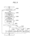
- FIG. 3 illustrates a flowchart of control in the embodiment.
- an accelerator off determination S201 when an accelerator pedal depression amount is detected to be zero by the accelerator depression amount detecting means 113, an accelerator off is determined, and the progress proceeds to S202.
- the accelerator pedal depression amount is not zero, the process of the control is terminated.
- M is a vehicle weight
- C d is an air resistance coefficient
- S is a front projection area of the vehicle
- V is a vehicle speed
- ⁇ is a rolling resistance coefficient
- g is a gravitational acceleration
- ⁇ is a road surface gradient.
- F e represents the engine loss torque in a state in which the torque converter 116 and the clutch mechanism 119 are engaged, with the fuel supply to the engine 101 stopped.
- the engine loss torque F e changes by the engine speed. Also, since the gear ratio of the transmission mechanism 118 varies by the vehicle speed, the engine rotation speed also changes. Therefore, as illustrated in FIG. 4 , in the transmission ratio calculation 301, first, the transmission ratio is calculated on the basis of the transmission line when the accelerator depression amount is zero, and the engine rotation speed is output on the basis of the vehicle speed and the transmission ratio. Next, in the engine loss torque calculation 302, the engine loss torque F e is calculated on the basis of the engine rotation speed.
- the transmission line when the accelerator depression amount is zero it is possible to minimize the engine rotation speed, and as a result, it is possible to minimize the engine loss torque.
- a required deceleration estimation S204 the deceleration required by the driver is estimated. Specifically, as illustrated in the required deceleration calculation (driver operation) 401 of FIG. 5 , when the brake pedal depression amount is equal to or larger than zero and equal to or less than a predetermined value b on by the brake pedal depression amount detecting means 113 (region I), it is determined that there is a driving intention due to inertia, and the required deceleration ⁇ d , which is the deceleration required from the driver by the driver operation, is set as the vehicle deceleration ⁇ s at the time of clutch disengagement.
- b on is a region (brake play) in which no brake braking force is generated.
- the setting is made so that a larger braking force is generated as the depression amount of the brake is larger.
- the required deceleration estimation S204 is not limited to FIG. 5 and may be set as illustrated in FIG. 6 .
- the dotted line of FIG. 6 is the deceleration that occurs at the time of engine brake and at the time of sailing stop.
- the brake depression amount is larger than the predetermined value b on (region II)
- since torque of the engine loss is transmitted to the wheels at the time of engine brake deceleration greater at the time of engine brake than at the time of sailing stop is required for the same brake pedal depression amount, and discomfort arises in the brake feeling. Therefore, as illustrated in FIG.
- the required deceleration ⁇ d is compared with the vehicle deceleration ⁇ s at the time of clutch disengagement.
- the process proceeds to S206, and when ⁇ d is smaller than ⁇ s , the process proceeds to S207.
- a first traveling state of S206 as illustrated in FIG. 7(a) , the clutch mechanism 119 is set in a disengaged state and traveling is performed in a state in which fuel supply to the engine 101 is stopped.
- the clutch mechanism 119 is disengaged, the torque converter 116 may be kept in the engaged state.
- the required deceleration ⁇ d is compared with the vehicle deceleration ⁇ e at the time of clutch engagement.
- the process proceeds to S208, and when the required deceleration ⁇ d is larger than ⁇ e , the process proceeds to S209.
- a second traveling state of S208 as illustrated in FIG. 7(b) , the torque converter 116 and the clutch mechanism 119 are set in the engaged state together, and traveling is performed in the state in which fuel supply to the engine 101 is stopped (so-called engine brake state).
- a third traveling state of S209 as illustrated in FIG. 7(c) , the clutch mechanism 119 is set in the engaged state and the torque converter 116 is set in the disengaged state to perform deceleration by transmission loss. In this case, the fuel supply to the engine 101 may be stopped.
- the vehicle control device controls a vehicle which has a power transmission mechanism for controlling the power transmission state between the engine and the axle to one of transmission, half-transmission, and shutoff, and braking means for obtaining deceleration.
- the vehicle control device attains a fuel stop traveling state in which fuel supply to the engine is stopped, attains the fuel stop traveling state, controls the power transmission mechanism to the shutoff state, and controls the braking means to obtain a deceleration smaller than the deceleration of the vehicle in a traveling state in which the transmission mechanism is controlled to the transmission.
- a target loss torque F t is calculated by the formula (3) on the basis of the required deceleration ⁇ d and the vehicle deceleration ⁇ s at the time of clutch disengagement.
- F t M ⁇ d ⁇ ⁇ s
- a transmission loss lower limit value F m_min is calculated on the basis of the vehicle speed and the transmission ratio.
- FIG. 9 A specific process is illustrated in FIG. 9 .
- the vehicle speed is input to a transmission input rotation speed calculation 601, and the transmission input rotation speed is calculated on the basis of the transmission line when the accelerator depression amount is zero.
- the torque transmitted to the wheels 104 when switching from the second traveling state to the first traveling state decreases, and the shock at the time of switching is reduced.
- a lower limit pressure P min of the transmission oil pump and the transmission input rotation speed are input to the transmission torque loss 602, and the transmission torque loss lower limit value F m_min is calculated.
- the lower limit pressure P min of the transmission oil pump is calculated on the basis of the minimum pressure required to set the clutch mechanism 119 or the like in an engaged state.
- step S503 the transmission loss lower limit value F m_min is compared with the target loss torque F t .
- the process proceeds to step S504, the clutch mechanism 119 is set in the disengaged state, and the process is terminated.
- the clutch mechanism 119 is set in the engaged state, and the transmission loss is adjusted by controlling the transmission ratio.
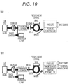
- the control mode in the third traveling state according to the present embodiment is not limited to FIG. 7(c) , and as illustrated in FIG. 10(a) , deceleration may be performed only by the brake mechanism 115 after the clutch mechanism 119 is set in the disengaged state. Also, as illustrated in FIG. 10(b) , the control mode may be a cooperative control of the brake mechanism 115 and the power transmission mechanism.
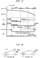
- loss of the power transmission mechanism is generated with priority. That is, as illustrated in FIG. 12 , this means that the clutch mechanism 119 is engaged and the transmission input rotation speed is increased.
- the torque converter can be quickly set in the engaged state. Further, in a case where the target loss torque difference cannot be covered by the transmission loss, it is possible to achieve the required deceleration by adjusting the brake loss amount, and the drivability is improved.
- the vehicle control device of the present embodiment when driving a vehicle capable of changing a plurality of different traveling states of a power transmission state or a traveling state of the engine during traveling, by appropriately controlling the vehicle, it is possible to reduce discomfort of the driver. That is, according to the vehicle control device of this embodiment, it is possible to generate a deceleration which is larger than the deceleration at the time of sailing stop traveling and smaller than the deceleration at the time of engine brake traveling. Therefore, it also leads to an improvement in operability of the driver when the driver performs a manual operation. Further, utilization of the power shutoff brake traveling state as described above by way of example of the vehicle control device is effective not only in a manual operation but also in an automatic operation in order to reduce the discomfort of the driver.
- a vehicle having means capable of adjusting the air resistance in the traveling resistance of the vehicle will be described.
- means capable of adjusting the air resistance as illustrated in FIG. 13 , there are a front air resistance adjustment mechanism 801 attached to the front of the vehicle, a rear air resistance adjustment mechanism 802 attached to the rear of the vehicle, and the like.
- An example of the front air resistance adjustment mechanism 801 is to control the flow of air by opening and closing the shutter, and the air resistance becomes larger in the open state of the shutter than in the closed state of the shutter.
- An example of the rear air resistance adjustment mechanism 802 is to control the flow of air by switching between the stored state and the non-stored state of the spoiler and by adjusting the angle of the spoiler in the non-stored state, and in a state in which the spoiler appears and as the angle is larger, the air resistance is larger.
- the target loss torque F t is calculated by the formula (3) on the basis of the required deceleration ⁇ d and the vehicle deceleration ⁇ s at the time of clutch disengagement.
- the transmission loss lower limit value F m_min is calculated on the basis of the vehicle speed and the transmission ratio.
- the lower limit pressure P min of the transmission oil pump and the transmission input rotation speed are input to the transmission torque loss- 602, and the transmission torque loss lower limit value F m_min is calculated.
- the lower limit pressure P min of the transmission oil pump is calculated on the basis of the minimum pressure required to set the clutch mechanism 119 or the like in an engaged state.
- the transmission loss lower limit value F m_min is compared with the target loss torque F t , and when the target loss torque F t is smaller than the transmission loss lower limit value F m_min , the process proceeds to S901, and when the target loss torque F t is larger than the transmission loss lower limit value F m_min , the process proceeds to the cooperative deceleration adjustment process of the power transmission mechanism and brake of S505.
- the loss of the power transmission mechanism is generated with priority. That is, as illustrated in FIG. 7 , this means that the clutch mechanism 119 is engaged and the transmission input rotation speed is increased.
- the means capable of adjusting the air resistance outputs the result of selecting the smaller value between the maximum value C d_max of the C d value which can change in that state and the target C d value C dt , as the upper limit value f a_max of the air resistance loss.
- f a _ max ⁇ min C dt , C d _ max ⁇ C d 2 S V 2
- the target loss torque F t is achieved by compensating for the loss torque which cannot be achieved in the air resistance loss f a_max , by the brake loss amount. This makes it possible to reduce the burden of the brake loss amount, and it is possible to prevent overheating or wear of the brake pad.
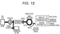
- the control mode in the third traveling state according to the present embodiment is not limited to FIG. 15 .
- deceleration may be performed only by the means capable of adjusting the air resistance.
- FIG. 16(b) it is also possible to perform deceleration by a cooperative control of means capable of adjusting air resistance and the power transmission mechanism.
- the deceleration may be performed by the cooperative control of the brake mechanism 115 and the means capable of adjusting the air resistance.
- FIG. 18 is a diagram illustrating the configuration of the vehicle control device in this embodiment.
- the present embodiment further includes front situation recognizing means 1101.
- the front situation recognizing means 1101 includes at least one element such as a navigation system, a camera, a radar, an inter-vehicle communication or a road-to-vehicle communication module.
- the required deceleration estimation S204 using the front situation recognizing means in this embodiment will be described. Specifically, when it is determined that the preceding vehicle is not detected, the required deceleration (system determination) is output as 0, and when it is determined that the preceding vehicle is detected, as illustrated in FIG. 19 , a required deceleration calculation (system determination) 1201 is calculated and output, on the basis of a relative speed V r and an inter-vehicle time THW.
- the relative speed V r and the inter-vehicle time THW are calculated by the formulas (7) and (8).
- V r V f ⁇ V e
- THW D
- V f is the speed of the preceding vehicle
- V e is the speed of the own vehicle
- D is the distance between the own vehicle and the preceding vehicle
- the setting is made so that the required deceleration becomes smaller as the inter-vehicle time is smaller and the relative speed is larger.
- C represents a driver-dependent constant.
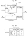
- C is not limited to a fixed value and may be switched in accordance with a traveling scene or the like. Specifically, as illustrated in FIG. 20 , the traveling state of the own vehicle is classified into "acceleration”, “constant speed”, and “deceleration” on the basis of the own vehicle speed, and C is changed on the basis of the current traveling state and a traveling state predicted by the front situation recognizing means.
- C represents the strength of the driver's response accompanied with change in the front situation.
- the magnitude relation is set as C4 > C2 > C3 > C1.
- the predicted traveling state is determined on the basis of preceding vehicle information (deceleration, brake lamp, and turn signal of the preceding vehicle) and road information (signal color, intersection, curve, uphill gradient, downhill gradient, etc.). As a result, the estimation accuracy of the required deceleration of the driver accompanied with the change in the front situation is improved.
- the front required deceleration ⁇ d adopts the smaller deceleration between the required deceleration (driver operation) 401 and the required deceleration (system determination) 901, as the required deceleration. As a result, it is possible to achieve an appropriate deceleration, while ensuring safety. Further, since the system achieves appropriate deceleration, it is possible to reduce the frequency of driver's operation and improve comfort.
Abstract
Description
- The present invention relates to a vehicle control device.
- There is
PTL 1 as a background art of this technical field. The publication ofPTL 1 discloses a vehicle control device in which a lower limit vehicle speed and an upper limit vehicle speed are set, and when the vehicle speed becomes equal to or higher than the upper limit vehicle speed, an engine is stopped, a power transmission mechanism between the engine and the wheels is opened, the vehicle is driven by coasting, and when the vehicle speed is equal to or lower than the lower limit vehicle speed, the engine is started, the power transmission mechanism is set in an engaged state to perform acceleration. Further,PTL 1 discloses a vehicle control device which determines whether or not it is necessary to stop the vehicle by detecting a signal or the like, and when it is determined to be necessary to stop the vehicle, the engine is continuously stopped up to a vehicle stop position to decelerate the vehicle by coasting. - Here, when the power transmission mechanism is set in an engaged state, the fuel supply to the engine is stopped and the vehicle is driven (engine brake), the deceleration of the engine brake becomes an addition of engine loss (mechanical loss, intake loss, etc.) to the traveling resistance. On the other hand, when the vehicle is caused to travel in a state in which the engine is stopped and the power transmission mechanism is disengaged (sailing stop), since the deceleration of the sailing stop is only the traveling resistance, the deceleration of the sailing stop becomes smaller than the deceleration of the engine brake.
- Therefore,
PTL 1 discloses a vehicle control device in which, when it is determined that there is a need to stop the vehicle and the distance up to the stop is equal to or larger than a predetermined value, the sailing stop is executed, and when the distance up to the stop becomes less than the predetermined value, by decelerating the vehicle with engine brake or brake, it is possible to lengthen the engine stop time to improve fuel economy. - PTL 1: Japanese Patent Application Laid-Open No.
2012-47148 - In
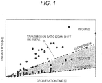
PTL 1, when it is determined to be necessary to stop the vehicle, the sailing stop and the engine brake are switched. However, there is a difference between the deceleration at the time of sailing stop traveling and the deceleration at the time of engine brake traveling. When it is necessary to slow moderate deceleration (such as when traveling to follow the preceding vehicle, etc.) by merely switching to either one, operability deteriorates. A specific explanation thereof is illustrated inFIG. 1 . - In
FIG. 1 , a horizontal axis represents deceleration time, a vertical axis represents energy loss, and each point represents required deceleration with respect to a representative deceleration pattern. The required deceleration is small at the time of the deceleration pattern of the lower right of the graph, and the required deceleration is large at the time of deceleration pattern of the upper left of the graph. Each line illustrates the degree of deceleration when traveling with the engine brake and when traveling with the sailing stop. In a region I, by shifting the transmission ratio to a low side in the engine brake state, or by applying the brake, a desired deceleration is obtained. On the other hand, in a region II, in the deceleration pattern in which the deceleration is larger than the sailing stop and smaller than the engine brake, there is no means to be adjusted at present, and a difference from the required deceleration occurs . In this case, there is a problem that the deceleration assumed by a driver depending on the situation deviates from the actual deceleration of the vehicle, which may cause the driver to feel discomfort. - An object of the present invention is to reduce discomfort of a driver by appropriately controlling a vehicle when driving a vehicle capable of changing a plurality of different traveling states of a power transmission state or traveling state of an engine during traveling.
- The present invention is a vehicle control device for controlling a vehicle having a power transmission mechanism which controls a power transmission state between an engine and an axle, and braking means. The vehicle control device includes, as vehicle traveling states, a power transmission engine stop traveling state in which power is transmitted by the power transmission mechanism and fuel supply to the engine is stopped to cause the vehicle to travel, and a power shutoff brake traveling state in which power from the power transmission mechanism is shut off, the fuel supply to the engine is stopped, the braking means is controlled so that the braking force is smaller than the power transmission engine stop traveling state, and the vehicle is caused to travel.
- According to the invention, it is possible to reduce discomfort of a driver by appropriately controlling a vehicle when driving a vehicle capable of changing a plurality of different traveling states of a power transmission state or traveling state of an engine during traveling.
-
- [
FIG. 1] FIG. 1 is a diagram illustrating a relation between deceleration time and energy loss for traveling with engine brake and traveling at sailing stop. - [
FIG. 2] FIG. 2 is a diagram illustrating a configuration of a vehicle provided with a vehicle control device according to a first embodiment. - [
FIG. 3] FIG. 3 is a flow chart of control in the first embodiment. - [
FIG. 4] FIG. 4 is a block diagram illustrating calculation of engine loss torque in the first embodiment. - [
FIG. 5] FIG. 5 is a block diagram illustrating required deceleration calculation in the first embodiment. - [
FIG. 6] FIG. 6 is a diagram illustrating a correction method of the required deceleration calculation in the first embodiment. - [
FIG. 7] FIG. 7 is a diagram illustrating a traveling state in the first embodiment. - [
FIG. 8] FIG. 8 is a flowchart of a third traveling state in the first embodiment. - [
FIG. 9] FIG. 9 is a block diagram illustrating the calculation of a transmission loss torque lower limit value in the first embodiment. - [
FIG. 10] FIG. 10 is a diagram illustrating a control mode of the third traveling state in the first embodiment. - [
FIG. 11] FIG. 11 is a flowchart at the time of cooperation with the brake of the third traveling state in the first embodiment. - [
FIG. 12] FIG. 12 is a time chart in the first embodiment. - [
FIG. 13] FIG. 13 is a diagram illustrating the configuration of a vehicle including the vehicle control device according to a second embodiment. - [
FIG. 14] FIG. 14 is a flowchart of the third traveling state in the second embodiment. - [
FIG. 15] FIG. 15 is a diagram illustrating a control mode of a third traveling state in the second embodiment. - [
FIG. 16] FIG. 16 is a diagram illustrating another control mode of the third traveling state in the second embodiment. - [
FIG. 17] FIG. 17 is a time chart in the second embodiment. - [
FIG. 18] FIG. 18 is a diagram illustrating a configuration of a vehicle control device according to a third embodiment. - [
FIG. 19] FIG. 19 is a block diagram illustrating required deceleration calculation in the third embodiment. - [
FIG. 20] FIG. 20 is a diagram illustrating the reaction intensity of the driver in the third embodiment. - Hereinafter, embodiments of the present invention will be described with reference to the drawings.
-
FIG. 2 is a diagram illustrating a configuration of a vehicle provided with a vehicle control device in this embodiment. As illustrated inFIG. 2 , anengine 101 is mounted on thevehicle 100. The driving force generated by theengine 101 is transmitted towheels 104 connected via adifferential mechanism 103 through apower transmission mechanism 102, thereby causing thevehicle 100 to travel. Further, in order to decelerate thevehicle 100,wheels 104 are provided with abrake mechanism 115. The braking force is changed by a pressing amount of a brake pad in thebrake mechanism 115, and the speed of thevehicle 100 is adjusted. - The
power transmission mechanism 102 includes atorque converter 116, anoil pump 117, atransmission mechanism 118, and aclutch mechanism 119 capable of transmitting and cutting off the power from theengine 101 to thewheels 104. Further, theoil pump 117 is driven via an oilpump driving chain 120. - Here, the
transmission mechanism 118 is not limited to a stepped transmission, but may be a continuously variable transmission in which a belt or a chain and a pulley are combined with each other. Theclutch mechanism 119 may be provided between the oilpump driving chain 120 and thetransmission mechanism 118, without being limited to being disposed between thetransmission mechanism 118 and thedifferential mechanism 103. - A
starter motor 105 is assembled to theengine 101 as a startup device. Thestarter motor 105 is driven by supplying the electric power from abattery 108, and theengine 101 also rotates in conjunction with the rotation of thestarter motor 105. Here, a motor having functions of a starter motor and a generator may be used as the engine startup device, without being limited to thestarter motor 105. Means 121 for detecting the rotation speed of the engine is attached to theengine 101. The engine is started by driving thestarter motor 105 to start the fuel supply and perform ignition when the engine rotation speed reaches a predetermined value or higher. - A
generator 106 is connected to theengine 101 via adrive belt 107. Thegenerator 106 can generate electric power by being rotated in accordance with the rotation of the crankshaft. Thegenerator 106 has a mechanism for varying the generated voltage by controlling the field current and can stop the power generation output. - The electric power generated by the
generator 106 is supplied to thebattery 108 and the in-vehicleelectric component 109. The in-vehicleelectric component 109 also includes an actuator for operating theengine 101, for example, a fuel supply device, an ignition device, and acontroller 111 for controlling them, and is configured to include a lighting device such as a headlight, a brake lamp, and a direction indicator, and an air conditioner such as a blower fan and a heater. - Information detected by accelerator pedal depression amount detecting means 112 for detecting a depression amount of an accelerator pedal, brake pedal depression amount detecting means 113 for detecting a depression amount of brake pedal, and a vehicle speed detecting means 114 for detecting the speed of the vehicle is input to the
controller 111. - The
brake mechanism 115 may be provided with a mechanism for controlling the braking force by changing a pressing amount of the brake pad in accordance with the brake pedal depression amount of the driver, and an electric actuator mechanism capable of changing the pressing amount by a command value from thecontroller 111. - Further, the vehicle control device according to the present embodiment has, as vehicle traveling states, a power transmission engine stop traveling state (specifically, a second traveling state to be described later), a power shutoff brake traveling state (specifically, a third traveling state to be described later), and a coasting travel state (specifically, a first traveling state to be described later) . The power transmission engine stop traveling state is a mode in which the power is transmitted by the power transmission mechanism, and the fuel supply to the engine is stopped to allow the vehicle to travel. The power shutoff brake traveling state is a mode in which the power from the power transmission mechanism is shut off, the fuel supply to the engine is stopped, and the braking means is controlled so that the braking force becomes smaller than the power transmission engine stop traveling state to allow the vehicle to travel. The coasting travel state is a mode in which power from the power transmission mechanism is shut off, fuel supply to the engine is stopped, and the vehicle is allowed to travel by inertia without performing braking using the braking means.
- The control method in the first embodiment will be described in detail with reference to
FIGS. 3 through 7 . First,FIG. 3 illustrates a flowchart of control in the embodiment. - In an accelerator off determination S201, when an accelerator pedal depression amount is detected to be zero by the accelerator depression amount detecting means 113, an accelerator off is determined, and the progress proceeds to S202. When the accelerator pedal depression amount is not zero, the process of the control is terminated.
- In a deceleration estimation at the time of clutch disengagement S202, the vehicle deceleration αs at the time of disengaging of the clutch is estimated by the formula (1).
[Formula 1]
- Here, M is a vehicle weight, Cd is an air resistance coefficient, S is a front projection area of the vehicle, V is a vehicle speed, µ is a rolling resistance coefficient, g is a gravitational acceleration, and θ is a road surface gradient.
- In a deceleration estimation at the time of clutch engagement S203, the vehicle deceleration αe at the time of clutch engagement is estimated by the formula (2).
[Formula 2]
- Here, Fe represents the engine loss torque in a state in which the
torque converter 116 and theclutch mechanism 119 are engaged, with the fuel supply to theengine 101 stopped. - The engine loss torque Fe changes by the engine speed. Also, since the gear ratio of the
transmission mechanism 118 varies by the vehicle speed, the engine rotation speed also changes. Therefore, as illustrated inFIG. 4 , in thetransmission ratio calculation 301, first, the transmission ratio is calculated on the basis of the transmission line when the accelerator depression amount is zero, and the engine rotation speed is output on the basis of the vehicle speed and the transmission ratio. Next, in the engineloss torque calculation 302, the engine loss torque Fe is calculated on the basis of the engine rotation speed. Here, by using the transmission line when the accelerator depression amount is zero, it is possible to minimize the engine rotation speed, and as a result, it is possible to minimize the engine loss torque. - In a required deceleration estimation S204, the deceleration required by the driver is estimated. Specifically, as illustrated in the required deceleration calculation (driver operation) 401 of
FIG. 5 , when the brake pedal depression amount is equal to or larger than zero and equal to or less than a predetermined value bon by the brake pedal depression amount detecting means 113 (region I), it is determined that there is a driving intention due to inertia, and the required deceleration αd, which is the deceleration required from the driver by the driver operation, is set as the vehicle deceleration αs at the time of clutch disengagement. Here, bon is a region (brake play) in which no brake braking force is generated. - When the depression amount is larger than the predetermined value bon (Region II), the setting is made so that a larger braking force is generated as the depression amount of the brake is larger.
- Here, the required deceleration estimation S204 is not limited to
FIG. 5 and may be set as illustrated inFIG. 6 . The dotted line ofFIG. 6 is the deceleration that occurs at the time of engine brake and at the time of sailing stop. In a case where the brake depression amount is larger than the predetermined value bon (region II), since torque of the engine loss is transmitted to the wheels at the time of engine brake, deceleration greater at the time of engine brake than at the time of sailing stop is required for the same brake pedal depression amount, and discomfort arises in the brake feeling. Therefore, as illustrated inFIG. 6 , when the brake depression amount is smaller than the predetermined value bon at the time of sailing stop (region I), the required deceleration αd, which is the deceleration required from the driver by the driver operation, is set as a vehicle deceleration αs at the time of clutch disengagement, and when the brake pedal depression amount is larger than the predetermined value bon (region II), the required deceleration αd, which is the deceleration required from the driver by the driver operation, is set as the deceleration at the time of engine brake. Thus, the same braking force can be generated for the same brake depression amount, and it is possible to expect to suppress degradation of operability. - In S205, the required deceleration αd is compared with the vehicle deceleration αs at the time of clutch disengagement. When the required deceleration αd is equal to or greater than αs, the process proceeds to S206, and when αd is smaller than αs, the process proceeds to S207.
- In a first traveling state of S206, as illustrated in
FIG. 7(a) , theclutch mechanism 119 is set in a disengaged state and traveling is performed in a state in which fuel supply to theengine 101 is stopped. Here, if theclutch mechanism 119 is disengaged, thetorque converter 116 may be kept in the engaged state. - In S207, the required deceleration αd is compared with the vehicle deceleration αe at the time of clutch engagement. When the required deceleration αd is equal to or less than αe, the process proceeds to S208, and when the required deceleration αd is larger than αe, the process proceeds to S209.
- In a second traveling state of S208, as illustrated in
FIG. 7(b) , thetorque converter 116 and theclutch mechanism 119 are set in the engaged state together, and traveling is performed in the state in which fuel supply to theengine 101 is stopped (so-called engine brake state). - In a third traveling state of S209, as illustrated in
FIG. 7(c) , theclutch mechanism 119 is set in the engaged state and thetorque converter 116 is set in the disengaged state to perform deceleration by transmission loss. In this case, the fuel supply to theengine 101 may be stopped. - Further, when as illustrated in
FIG. 7(a) , a state in which both thetorque converter 116 and theclutch mechanism 119 constituting the power transmission mechanism are engaged is set as a "transmission" state, as illustrated inFIG. 7(b) , a state in which both of them is released is set as a "shutoff", and as illustrated inFIG. 7(c) , a state in which thetorque converter 116 is released but theclutch mechanism 119 is engaged is set as a so-called "semi-transmission" state, the vehicle control device can also be expressed as follows. That is, the vehicle control device controls a vehicle which has a power transmission mechanism for controlling the power transmission state between the engine and the axle to one of transmission, half-transmission, and shutoff, and braking means for obtaining deceleration. The vehicle control device attains a fuel stop traveling state in which fuel supply to the engine is stopped, attains the fuel stop traveling state, controls the power transmission mechanism to the shutoff state, and controls the braking means to obtain a deceleration smaller than the deceleration of the vehicle in a traveling state in which the transmission mechanism is controlled to the transmission. - A specific process of S209 will be described with reference to
FIG. 8 . First, in S501, a target loss torque Ft is calculated by the formula (3) on the basis of the required deceleration αd and the vehicle deceleration αs at the time of clutch disengagement.
[Formula 3]
- Next, in S502, a transmission loss lower limit value Fm_min is calculated on the basis of the vehicle speed and the transmission ratio. A specific process is illustrated in
FIG. 9 . First, the vehicle speed is input to a transmission inputrotation speed calculation 601, and the transmission input rotation speed is calculated on the basis of the transmission line when the accelerator depression amount is zero. Here, by using the transmission line when the accelerator depression amount is zero, the torque transmitted to thewheels 104 when switching from the second traveling state to the first traveling state decreases, and the shock at the time of switching is reduced. - Next, a lower limit pressure Pmin of the transmission oil pump and the transmission input rotation speed are input to the
transmission torque loss 602, and the transmission torque loss lower limit value Fm_min is calculated. Here, the lower limit pressure Pmin of the transmission oil pump is calculated on the basis of the minimum pressure required to set theclutch mechanism 119 or the like in an engaged state. - In step S503, the transmission loss lower limit value Fm_min is compared with the target loss torque Ft. When the target loss torque Ft is smaller than the transmission loss lower limit value Fm_min, the process proceeds to step S504, the
clutch mechanism 119 is set in the disengaged state, and the process is terminated. When the target loss torque Ft is larger than the transmission loss lower limit value Fm_min, the process proceeds to S505, theclutch mechanism 119 is set in the engaged state, and the transmission loss is adjusted by controlling the transmission ratio. - The control mode in the third traveling state according to the present embodiment is not limited to
FIG. 7(c) , and as illustrated inFIG. 10(a) , deceleration may be performed only by thebrake mechanism 115 after theclutch mechanism 119 is set in the disengaged state. Also, as illustrated inFIG. 10(b) , the control mode may be a cooperative control of thebrake mechanism 115 and the power transmission mechanism. - A specific process of S209 using the brake mechanism and the power transmission mechanism will be described with reference to
FIG. 11 . When the target loss torque Ft is smaller than the transmission loss lower limit value Fm_min in S503, the clutch is set in the disengaged state, and the process proceeds to the deceleration adjustment process using the brake of S1101. This makes it possible to prevent a situation in which the transmission loss Fm_min becomes larger than the target loss torque Ft due to the engagement of theclutch mechanism 119, and the deceleration becomes smaller than the required deceleration. - On the other hand, when the target loss torque Ft is larger than the transmission loss lower limit value Fm_min, the process proceeds to the cooperative deceleration adjustment process of the power transmission mechanism and brake of S1102.
- In the cooperative deceleration adjustment process of the power transmission mechanism and brake S1102, loss of the power transmission mechanism is generated with priority. That is, as illustrated in
FIG. 12 , this means that theclutch mechanism 119 is engaged and the transmission input rotation speed is increased. Thus, when switching to the first traveling state, the torque converter can be quickly set in the engaged state. Further, in a case where the target loss torque difference cannot be covered by the transmission loss, it is possible to achieve the required deceleration by adjusting the brake loss amount, and the drivability is improved. - In the conventional vehicle control device, since an engine brake that performs braking by the engine loss has a relatively large braking force, braking is performed more than necessary, and in order to maintain or raise the speed, there was a case where the engine needs to be driven again.
- In this regard, according to the vehicle control device of the present embodiment, when driving a vehicle capable of changing a plurality of different traveling states of a power transmission state or a traveling state of the engine during traveling, by appropriately controlling the vehicle, it is possible to reduce discomfort of the driver. That is, according to the vehicle control device of this embodiment, it is possible to generate a deceleration which is larger than the deceleration at the time of sailing stop traveling and smaller than the deceleration at the time of engine brake traveling. Therefore, it also leads to an improvement in operability of the driver when the driver performs a manual operation. Further, utilization of the power shutoff brake traveling state as described above by way of example of the vehicle control device is effective not only in a manual operation but also in an automatic operation in order to reduce the discomfort of the driver.
- In the present embodiment, a vehicle having means capable of adjusting the air resistance in the traveling resistance of the vehicle will be described. Here, as means capable of adjusting the air resistance, as illustrated in
FIG. 13 , there are a front airresistance adjustment mechanism 801 attached to the front of the vehicle, a rear airresistance adjustment mechanism 802 attached to the rear of the vehicle, and the like. An example of the front airresistance adjustment mechanism 801 is to control the flow of air by opening and closing the shutter, and the air resistance becomes larger in the open state of the shutter than in the closed state of the shutter. An example of the rear airresistance adjustment mechanism 802 is to control the flow of air by switching between the stored state and the non-stored state of the spoiler and by adjusting the angle of the spoiler in the non-stored state, and in a state in which the spoiler appears and as the angle is larger, the air resistance is larger. - The control method of the present embodiment will be described with reference to
FIG. 14 . Specifically, as illustrated inFIG. 15 ,
first, in S501, the target loss torque Ft is calculated by the formula (3) on the basis of the required deceleration αd and the vehicle deceleration αs at the time of clutch disengagement. - Next, in S502, the transmission loss lower limit value Fm_min is calculated on the basis of the vehicle speed and the transmission ratio. Next, the lower limit pressure Pmin of the transmission oil pump and the transmission input rotation speed are input to the transmission torque loss- 602, and the transmission torque loss lower limit value Fm_min is calculated. Here, the lower limit pressure Pmin of the transmission oil pump is calculated on the basis of the minimum pressure required to set the
clutch mechanism 119 or the like in an engaged state. - In S503, the transmission loss lower limit value Fm_min is compared with the target loss torque Ft, and when the target loss torque Ft is smaller than the transmission loss lower limit value Fm_min, the process proceeds to S901, and when the target loss torque Ft is larger than the transmission loss lower limit value Fm_min, the process proceeds to the cooperative deceleration adjustment process of the power transmission mechanism and brake of S505.
- In the cooperative deceleration adjustment process of the power transmission mechanism and brake S505, the loss of the power transmission mechanism is generated with priority. That is, as illustrated in
FIG. 7 , this means that theclutch mechanism 119 is engaged and the transmission input rotation speed is increased. - In S901, the upper limit value fa_max of the air resistance loss is calculated. Specifically, the air resistance loss fa is calculated by the formula (4), and the air resistance loss is adjusted by changing the Cd value.
[Formula 4]
- Therefore, when the Cd value in the second traveling state is set as Cd2, and when the target Cd value in the third traveling state is set as Cdt, an air resistance loss increase fa_s can be calculated by formula (5).
[Formula 5]
- Here, since Cdt is limited by the control state of the means capable of adjusting the air resistance, as illustrated in the formula (6), the means capable of adjusting the air resistance outputs the result of selecting the smaller value between the maximum value Cd_max of the Cd value which can change in that state and the target Cd value Cdt, as the upper limit value fa_max of the air resistance loss.
[Formula 6]
- In S902, as illustrated in
FIG. 17 , the target loss torque Ft is achieved by compensating for the loss torque which cannot be achieved in the air resistance loss fa_max, by the brake loss amount. This makes it possible to reduce the burden of the brake loss amount, and it is possible to prevent overheating or wear of the brake pad. - The control mode in the third traveling state according to the present embodiment is not limited to
FIG. 15 . As illustrated inFIG. 16(a) , after theclutch mechanism 119 is set in the disengaged state, deceleration may be performed only by the means capable of adjusting the air resistance. Further, as illustrated inFIG. 16(b) , it is also possible to perform deceleration by a cooperative control of means capable of adjusting air resistance and the power transmission mechanism. Further, as illustrated inFIG. 16(c) , the deceleration may be performed by the cooperative control of thebrake mechanism 115 and the means capable of adjusting the air resistance. -
FIG. 18 is a diagram illustrating the configuration of the vehicle control device in this embodiment. - The present embodiment further includes front
situation recognizing means 1101. The frontsituation recognizing means 1101 includes at least one element such as a navigation system, a camera, a radar, an inter-vehicle communication or a road-to-vehicle communication module. - The required deceleration estimation S204 using the front situation recognizing means in this embodiment will be described. Specifically, when it is determined that the preceding vehicle is not detected, the required deceleration (system determination) is output as 0, and when it is determined that the preceding vehicle is detected, as illustrated in
FIG. 19 , a required deceleration calculation (system determination) 1201 is calculated and output, on the basis of a relative speed Vr and an inter-vehicle time THW. Here, the relative speed Vr and the inter-vehicle time THW are calculated by the formulas (7) and (8).
[Formula 7]
[Formula 8]
- Here, Vf is the speed of the preceding vehicle, Ve is the speed of the own vehicle, D is the distance between the own vehicle and the preceding vehicle, and the setting is made so that the required deceleration becomes smaller as the inter-vehicle time is smaller and the relative speed is larger. Also, the required deceleration may be calculated using the formula (9) on the basis of the relative speed Vr and the inter-vehicle time THW.
[Formula 9]
- Here, C represents a driver-dependent constant. C is not limited to a fixed value and may be switched in accordance with a traveling scene or the like. Specifically, as illustrated in
FIG. 20 , the traveling state of the own vehicle is classified into "acceleration", "constant speed", and "deceleration" on the basis of the own vehicle speed, and C is changed on the basis of the current traveling state and a traveling state predicted by the front situation recognizing means. C represents the strength of the driver's response accompanied with change in the front situation. Therefore, when a case where there is no change between the current traveling state and the predicted traveling state is set as C1, the case of turning to acceleration is set as C2, the case of turning to constant speed is set as C3, and the case of turning to deceleration is set as C4, the magnitude relation is set as C4 > C2 > C3 > C1. The predicted traveling state is determined on the basis of preceding vehicle information (deceleration, brake lamp, and turn signal of the preceding vehicle) and road information (signal color, intersection, curve, uphill gradient, downhill gradient, etc.). As a result, the estimation accuracy of the required deceleration of the driver accompanied with the change in the front situation is improved. - The front required deceleration αd adopts the smaller deceleration between the required deceleration (driver operation) 401 and the required deceleration (system determination) 901, as the required deceleration. As a result, it is possible to achieve an appropriate deceleration, while ensuring safety. Further, since the system achieves appropriate deceleration, it is possible to reduce the frequency of driver's operation and improve comfort.
-
- 100
- vehicle
- 101
- engine
- 102
- power transmission mechanism
- 103
- final decelerator
- 104
- differential speed reducer
- 105
- starter motor
- 106
- generator
- 107
- drive belt
- 108
- battery
- 109
- in-vehicle electric component
- 111
- controller
- 112
- accelerator depression amount detecting means
- 113
- brake depression amount detecting means
- 114
- vehicle speed detecting means
- 115
- brake mechanism
- 116
- torque converter
- 117
- oil pump
- 118
- transmission mechanism
- 119
- clutch mechanism
- 120
- oil pump driving chain
- 121
- engine rotation speed detecting means
- 1101
- front situation recognizing means
Claims (17)
- A vehicle control device for controlling a vehicle having a power transmission mechanism which controls a power transmission state between an engine and an axle, and braking means, the vehicle control device comprising, as vehicle traveling states,
a power transmission engine stop traveling state in which power is transmitted by the power transmission mechanism and fuel supply to the engine is stopped to cause the vehicle to travel, and
a power shutoff brake traveling state in which power from the power transmission mechanism is shut off, the fuel supply to the engine is stopped, the braking means is controlled so that the braking force is smaller than the power transmission engine stop traveling state, and the vehicle is caused to travel. - The vehicle control device according to claim 1, further comprising:
as the vehicle traveling state, a coasting travel state in which the power from the power transmission mechanism is shut off, the fuel supply to the engine is stopped, and the vehicle is caused to travel by inertia without braking using the braking means. - The vehicle control device according to claim 1, wherein the vehicle control device controls a vehicle having front situation recognizing means for detecting a front situation, and
the vehicle traveling state is selected from a plurality of vehicle traveling states, on the basis of the front situation recognizing means. - The vehicle control device according to claim 1, further comprising:
required deceleration estimating means for estimating a required deceleration, the vehicle being caused to travel in a traveling state selected from the respective traveling states, on the basis of the deceleration estimated by the required deceleration estimating means. - The vehicle control device according to claim 4, further comprising:means for detecting an operation amount of an accelerator pedal, and means for detecting an operation amount of a brake pedal,wherein the required deceleration estimating means estimates a required deceleration, on the basis of an accelerator pedal operation amount and a brake pedal operation amount.
- The vehicle control device according to claim 4, further comprising:means for detecting the operation amount of the accelerator pedal, and means for detecting the operation amount of the brake pedal,wherein the required deceleration estimating means sets the required deceleration to a predetermined value until an operation amount threshold value generating the braking force from the accelerator pedal operation amount of zero and the brake pedal operation amount of zero, and when the brake pedal operation amount becomes larger than the operation amount threshold value generating the braking force, the required deceleration estimating means estimates the required deceleration to decrease in accordance with the brake pedal operation amount.
- The vehicle control device according to claim 4, further comprising:front situation recognizing means for recognizing a front situation of the own vehicle, means for detecting an operation amount of the accelerator pedal, and means for detecting the operation amount of the brake pedal,wherein the required deceleration estimating means compares a system-required deceleration calculated on the basis of the front situation recognition with a driver-required deceleration calculated on the basis of the accelerator pedal operation amount and the brake pedal operation amount, and outputs the smaller deceleration as the required deceleration.
- The vehicle control device according to claim 1, wherein the braking means controls at least one or more of a transmission mechanism capable of adjusting the transmission loss, a brake mechanism capable of controlling the braking force irrespective of the brake pedal operation amount, or means capable of adjusting the air resistance, thereby adjusting the vehicle deceleration.
- The vehicle control device according to claim 8, further comprising:required deceleration estimating means for estimating a required deceleration,wherein the braking means changes a ratio of a loss amount caused by the transmission mechanism and a loss amount caused by the brake mechanism, on the basis of the required deceleration estimated by the required deceleration estimating means and the vehicle speed information.
- The vehicle control device according to claim 8, wherein the loss amount caused by the transmission mechanism is adjusted by controlling a line pressure of the transmission, in a state of the transmission ratio of the transmission when the operation of the accelerator pedal is zero.
- The vehicle control device according to claim 8, further comprising:required loss torque means for calculating a required loss torque on the basis of the deceleration estimated by the required deceleration estimating means,wherein, when a minimum value of the loss torque caused by the transmission mechanism is larger than the required loss torque, the required loss torque is output by the brake mechanism.
- The vehicle control device according to claim 1, further comprising:required deceleration estimating means for estimating a required deceleration, andrequired loss torque means for calculating a required loss torque on the basis of the deceleration estimated by the required deceleration estimating means,wherein, when a minimum value of the loss torque caused by the transmission mechanism is larger than the required loss torque, loss torque of the transmission is generated by the transmission mechanism, and a difference between the required loss torque and the loss torque of the transmission is adjusted by the brake mechanism.
- The vehicle control device according to claim 1, further comprising:required deceleration estimating means for estimating a required deceleration,wherein the braking means changes a ratio of a loss amount caused by the air resistance adjustable means and a loss amount caused by the brake mechanism, on the basis of the required deceleration estimated by the required deceleration estimating means and the vehicle speed information.
- The vehicle control device according to claim 2, further comprising:required deceleration estimating means for estimating a required deceleration,wherein, in the state of the power shutoff brake traveling state, when the required deceleration estimated by the required deceleration estimating means becomes smaller than the deceleration of the power shutoff brake traveling state, switching to the coasting travel state is performed, and when the required deceleration is larger than the deceleration of the power shutoff brake traveling state, switching to the power transmission engine stop traveling state is performed.
- The vehicle control device according to claim 7, wherein system-required deceleration calculated on the basis of the front situation recognition is corrected, depending on the deceleration of the preceding vehicle and the deceleration of the own vehicle.
- The vehicle control device according to claim 7, wherein the system-required deceleration calculated on the basis of the front situation recognition makes the correction amount when the deceleration of the preceding vehicle is larger than zero, larger than the correction amount at which the deceleration of the preceding vehicle is zero, and the system-required deceleration makes the correction amount when the deceleration of the preceding vehicle is smaller than zero, larger than the correction amount when the deceleration of the preceding vehicle is larger than zero.
- A vehicle control device for controlling a vehicle having a power transmission mechanism which controls a power transmission state between an engine and an axle, and braking means, the vehicle control device comprising, as vehicle traveling states,
a power transmission engine stop traveling state in which power is transmitted by the power transmission mechanism and fuel supply to the engine is stopped to cause the vehicle to travel, and
a power shutoff brake traveling state in which power from the power transmission mechanism is shut off, the fuel supply to the engine is stopped, and braking is performed by the braking means to cause the vehicle to travel,
wherein shifting from the power shutoff brake traveling state to another vehicle traveling state including the power transmission engine stop traveling state and having the vehicle speed greater than 0 is performed.
Applications Claiming Priority (2)
| Application Number | Priority Date | Filing Date | Title |
|---|---|---|---|
| JP2015190610A JP6553469B2 (en) | 2015-09-29 | 2015-09-29 | Vehicle control device |
| PCT/JP2016/073028 WO2017056723A1 (en) | 2015-09-29 | 2016-08-05 | Vehicle control device |
Publications (3)
| Publication Number | Publication Date |
|---|---|
| EP3357779A1 true EP3357779A1 (en) | 2018-08-08 |
| EP3357779A4 EP3357779A4 (en) | 2019-06-05 |
| EP3357779B1 EP3357779B1 (en) | 2020-12-16 |
Family
ID=58427401
Family Applications (1)
| Application Number | Title | Priority Date | Filing Date |
|---|---|---|---|
| EP16850900.8A Active EP3357779B1 (en) | 2015-09-29 | 2016-08-05 | Vehicle control device |
Country Status (5)
| Country | Link |
|---|---|
| US (1) | US10710589B2 (en) |
| EP (1) | EP3357779B1 (en) |
| JP (1) | JP6553469B2 (en) |
| CN (1) | CN108025750B (en) |
| WO (1) | WO2017056723A1 (en) |
Families Citing this family (10)
| Publication number | Priority date | Publication date | Assignee | Title |
|---|---|---|---|---|
| JP6361590B2 (en) * | 2015-06-16 | 2018-07-25 | トヨタ自動車株式会社 | Vehicle control device |
| DE102017211931B4 (en) * | 2017-07-12 | 2022-12-29 | Volkswagen Aktiengesellschaft | Method for adjusting at least one operating parameter of a motor vehicle, system for adjusting at least one operating parameter of a motor vehicle and motor vehicle |
| JP6481745B1 (en) * | 2017-11-24 | 2019-03-13 | マツダ株式会社 | Vehicle control device |
| JP6997413B2 (en) | 2018-03-28 | 2022-01-17 | マツダ株式会社 | Vehicle control device |
| JP7464355B2 (en) * | 2018-08-07 | 2024-04-09 | トヨタ自動車株式会社 | Braking force control device, control device, manager, method, program, actuator system, and vehicle |
| JP6719522B2 (en) * | 2018-09-18 | 2020-07-08 | 株式会社Subaru | Vehicle control device |
| JP7035995B2 (en) * | 2018-12-25 | 2022-03-15 | トヨタ自動車株式会社 | Driving support device |
| JP7207004B2 (en) * | 2019-02-25 | 2023-01-18 | トヨタ自動車株式会社 | electric vehicle controller |
| US11407302B2 (en) * | 2020-02-26 | 2022-08-09 | Borgwarner Inc. | Torque transfer assembly and vehicle including the same |
| US11491983B1 (en) * | 2021-06-04 | 2022-11-08 | Hyundai Motor Company | Vehicle coasting optimization |
Family Cites Families (16)
| Publication number | Priority date | Publication date | Assignee | Title |
|---|---|---|---|---|
| JP4501790B2 (en) | 2005-06-15 | 2010-07-14 | トヨタ自動車株式会社 | Vehicle deceleration control device |
| DE102007004412A1 (en) * | 2007-01-30 | 2008-07-31 | Zf Friedrichshafen Ag | Device for motor vehicle, has combustion engine, which stands in active connection with gearbox by automated clutch, where motor braking allows low transmission as transmissions for driving operations |
| JP2009051407A (en) * | 2007-08-28 | 2009-03-12 | Denso Corp | Vehicle controller and program |
| WO2009109826A1 (en) * | 2008-03-03 | 2009-09-11 | Nissan Motor Co., Ltd. | Control apparatus and method for controlling a hybrid vehicle |
| DE102008029453B4 (en) * | 2008-06-21 | 2021-01-28 | Bayerische Motoren Werke Aktiengesellschaft | Method for setting a so-called "sailing mode" in a motor vehicle |
| JP2012047148A (en) | 2010-08-30 | 2012-03-08 | Toyota Motor Corp | Control device of vehicle |
| JP5531915B2 (en) * | 2010-11-02 | 2014-06-25 | トヨタ自動車株式会社 | Vehicle control device |
| DE102011102332B3 (en) * | 2011-05-25 | 2012-10-25 | Audi Ag | Method for operating a longitudinal driver assistance system in a motor vehicle and motor vehicle |
| DE102011050739A1 (en) | 2011-05-31 | 2012-12-06 | Dr. Ing. H.C. F. Porsche Aktiengesellschaft | Method for operating motor vehicle, involves selecting distance-regulating operating mode or speed- and distance regulated operating mode, where immediately preceding motor vehicle is provided with respective changes |
| DE102012206135A1 (en) * | 2012-04-16 | 2013-10-17 | Ford Global Technologies, Llc | A method of switching from a sailing or free rolling operation of a motor vehicle to a fuel cut operation |
| JP6107824B2 (en) * | 2012-08-08 | 2017-04-05 | トヨタ自動車株式会社 | Vehicle travel control device |
| JP5741551B2 (en) * | 2012-10-24 | 2015-07-01 | トヨタ自動車株式会社 | Vehicle travel control device |
| WO2014068720A1 (en) * | 2012-10-31 | 2014-05-08 | トヨタ自動車株式会社 | Vehicle travel control device |
| WO2014068725A1 (en) * | 2012-10-31 | 2014-05-08 | トヨタ自動車株式会社 | Vehicle travel controller |
| GB2519161A (en) * | 2013-10-14 | 2015-04-15 | Gm Global Tech Operations Inc | Method of controlling aerodynamic devices in an automotive system during sailing driving |
| JP6065878B2 (en) * | 2014-06-09 | 2017-01-25 | トヨタ自動車株式会社 | Vehicle control apparatus and vehicle control method |
-
2015
- 2015-09-29 JP JP2015190610A patent/JP6553469B2/en active Active
-
2016
- 2016-08-05 EP EP16850900.8A patent/EP3357779B1/en active Active
- 2016-08-05 US US15/758,629 patent/US10710589B2/en active Active
- 2016-08-05 CN CN201680054876.1A patent/CN108025750B/en active Active
- 2016-08-05 WO PCT/JP2016/073028 patent/WO2017056723A1/en active Application Filing
Also Published As
| Publication number | Publication date |
|---|---|
| US10710589B2 (en) | 2020-07-14 |
| JP2017065327A (en) | 2017-04-06 |
| JP6553469B2 (en) | 2019-07-31 |
| EP3357779A4 (en) | 2019-06-05 |
| CN108025750B (en) | 2021-05-28 |
| CN108025750A (en) | 2018-05-11 |
| EP3357779B1 (en) | 2020-12-16 |
| WO2017056723A1 (en) | 2017-04-06 |
| US20180304892A1 (en) | 2018-10-25 |
Similar Documents
| Publication | Publication Date | Title |
|---|---|---|
| EP3357779B1 (en) | Vehicle control device | |
| EP3521594B1 (en) | Vehicle control device | |
| US10029689B2 (en) | Vehicle control apparatus | |
| US9561801B2 (en) | Vehicle control system | |
| JP6011572B2 (en) | Automobile | |
| CN110901625B (en) | Method and device for controlling a vehicle in a coasting mode | |
| JP2010143462A (en) | Auto-cruise control device for hybrid car and automatic braking control device for vehicle | |
| JP6304082B2 (en) | Vehicle control device | |
| US11505071B2 (en) | Regenerative braking control method and regenerative braking control device | |
| JP2010241245A (en) | Driving power controller for vehicle | |
| US11345345B2 (en) | Method for operating a motor vehicle, and corresponding motor vehicle | |
| JP2002142310A (en) | Motor torque controller for vehicle | |
| WO2019021687A1 (en) | Transmission control device | |
| CN110906001B (en) | Vehicle control device | |
| JPH1178598A (en) | Travel control device for vehicle | |
| JP2022062856A (en) | Vehicle control device | |
| JP2017115935A (en) | Vehicular shift control device | |
| JP3719032B2 (en) | Driving force control device for vehicle equipped with continuously variable transmission | |
| JP2005127424A (en) | Driving force control device for vehicle | |
| JP2017087799A (en) | Vehicle control apparatus | |
| JP2017088113A (en) | Drive power control apparatus | |
| JP2016185744A (en) | Vehicle speed control device | |
| JP5157834B2 (en) | Vehicle driving force control device | |
| JP5203910B2 (en) | Target drive control amount setting calculation device, vehicle travel system, and target drive control amount setting method | |
| CN112677775A (en) | Method and device for controlling crawling of electric automobile |
Legal Events
| Date | Code | Title | Description |
|---|---|---|---|
| STAA | Information on the status of an ep patent application or granted ep patent |
Free format text: STATUS: THE INTERNATIONAL PUBLICATION HAS BEEN MADE |
|
| PUAI | Public reference made under article 153(3) epc to a published international application that has entered the european phase |
Free format text: ORIGINAL CODE: 0009012 |
|
| STAA | Information on the status of an ep patent application or granted ep patent |
Free format text: STATUS: REQUEST FOR EXAMINATION WAS MADE |
|
| 17P | Request for examination filed |
Effective date: 20180322 |
|
| AK | Designated contracting states |
Kind code of ref document: A1 Designated state(s): AL AT BE BG CH CY CZ DE DK EE ES FI FR GB GR HR HU IE IS IT LI LT LU LV MC MK MT NL NO PL PT RO RS SE SI SK SM TR |
|
| AX | Request for extension of the european patent |
Extension state: BA ME |
|
| DAV | Request for validation of the european patent (deleted) | ||
| DAX | Request for extension of the european patent (deleted) | ||
| A4 | Supplementary search report drawn up and despatched |
Effective date: 20190508 |
|
| RIC1 | Information provided on ipc code assigned before grant |
Ipc: B60W 10/00 20060101ALI20190502BHEP Ipc: B60W 10/18 20120101ALI20190502BHEP Ipc: B60W 10/02 20060101ALI20190502BHEP Ipc: B60W 50/10 20120101ALI20190502BHEP Ipc: B60W 30/182 20120101AFI20190502BHEP Ipc: B60W 10/04 20060101ALI20190502BHEP Ipc: B62D 35/00 20060101ALI20190502BHEP Ipc: B60W 10/101 20120101ALI20190502BHEP Ipc: B60W 10/10 20120101ALI20190502BHEP Ipc: B60W 10/11 20120101ALI20190502BHEP Ipc: B60W 10/06 20060101ALI20190502BHEP Ipc: B60W 10/184 20120101ALI20190502BHEP Ipc: F16D 48/06 20060101ALI20190502BHEP Ipc: B62D 37/02 20060101ALI20190502BHEP |
|
| STAA | Information on the status of an ep patent application or granted ep patent |
Free format text: STATUS: EXAMINATION IS IN PROGRESS |
|
| 17Q | First examination report despatched |
Effective date: 20200115 |
|
| GRAP | Despatch of communication of intention to grant a patent |
Free format text: ORIGINAL CODE: EPIDOSNIGR1 |
|
| STAA | Information on the status of an ep patent application or granted ep patent |
Free format text: STATUS: GRANT OF PATENT IS INTENDED |
|
| INTG | Intention to grant announced |
Effective date: 20200814 |
|
| GRAS | Grant fee paid |
Free format text: ORIGINAL CODE: EPIDOSNIGR3 |
|
| GRAA | (expected) grant |
Free format text: ORIGINAL CODE: 0009210 |
|
| STAA | Information on the status of an ep patent application or granted ep patent |
Free format text: STATUS: THE PATENT HAS BEEN GRANTED |
|
| AK | Designated contracting states |
Kind code of ref document: B1 Designated state(s): AL AT BE BG CH CY CZ DE DK EE ES FI FR GB GR HR HU IE IS IT LI LT LU LV MC MK MT NL NO PL PT RO RS SE SI SK SM TR |
|
| REG | Reference to a national code |
Ref country code: GB Ref legal event code: FG4D |
|
| REG | Reference to a national code |
Ref country code: IE Ref legal event code: FG4D |
|
| REG | Reference to a national code |
Ref country code: DE Ref legal event code: R096 Ref document number: 602016050022 Country of ref document: DE |
|
| REG | Reference to a national code |
Ref country code: AT Ref legal event code: REF Ref document number: 1345336 Country of ref document: AT Kind code of ref document: T Effective date: 20210115 |
|
| PG25 | Lapsed in a contracting state [announced via postgrant information from national office to epo] |
Ref country code: FI Free format text: LAPSE BECAUSE OF FAILURE TO SUBMIT A TRANSLATION OF THE DESCRIPTION OR TO PAY THE FEE WITHIN THE PRESCRIBED TIME-LIMIT Effective date: 20201216 Ref country code: GR Free format text: LAPSE BECAUSE OF FAILURE TO SUBMIT A TRANSLATION OF THE DESCRIPTION OR TO PAY THE FEE WITHIN THE PRESCRIBED TIME-LIMIT Effective date: 20210317 Ref country code: RS Free format text: LAPSE BECAUSE OF FAILURE TO SUBMIT A TRANSLATION OF THE DESCRIPTION OR TO PAY THE FEE WITHIN THE PRESCRIBED TIME-LIMIT Effective date: 20201216 Ref country code: NO Free format text: LAPSE BECAUSE OF FAILURE TO SUBMIT A TRANSLATION OF THE DESCRIPTION OR TO PAY THE FEE WITHIN THE PRESCRIBED TIME-LIMIT Effective date: 20210316 |
|
| REG | Reference to a national code |
Ref country code: AT Ref legal event code: MK05 Ref document number: 1345336 Country of ref document: AT Kind code of ref document: T Effective date: 20201216 |
|
| REG | Reference to a national code |
Ref country code: NL Ref legal event code: MP Effective date: 20201216 |
|
| PG25 | Lapsed in a contracting state [announced via postgrant information from national office to epo] |
Ref country code: LV Free format text: LAPSE BECAUSE OF FAILURE TO SUBMIT A TRANSLATION OF THE DESCRIPTION OR TO PAY THE FEE WITHIN THE PRESCRIBED TIME-LIMIT Effective date: 20201216 Ref country code: BG Free format text: LAPSE BECAUSE OF FAILURE TO SUBMIT A TRANSLATION OF THE DESCRIPTION OR TO PAY THE FEE WITHIN THE PRESCRIBED TIME-LIMIT Effective date: 20210316 Ref country code: SE Free format text: LAPSE BECAUSE OF FAILURE TO SUBMIT A TRANSLATION OF THE DESCRIPTION OR TO PAY THE FEE WITHIN THE PRESCRIBED TIME-LIMIT Effective date: 20201216 |
|
| PG25 | Lapsed in a contracting state [announced via postgrant information from national office to epo] |
Ref country code: HR Free format text: LAPSE BECAUSE OF FAILURE TO SUBMIT A TRANSLATION OF THE DESCRIPTION OR TO PAY THE FEE WITHIN THE PRESCRIBED TIME-LIMIT Effective date: 20201216 Ref country code: NL Free format text: LAPSE BECAUSE OF FAILURE TO SUBMIT A TRANSLATION OF THE DESCRIPTION OR TO PAY THE FEE WITHIN THE PRESCRIBED TIME-LIMIT Effective date: 20201216 |
|
| REG | Reference to a national code |
Ref country code: LT Ref legal event code: MG9D |
|
| PG25 | Lapsed in a contracting state [announced via postgrant information from national office to epo] |
Ref country code: RO Free format text: LAPSE BECAUSE OF FAILURE TO SUBMIT A TRANSLATION OF THE DESCRIPTION OR TO PAY THE FEE WITHIN THE PRESCRIBED TIME-LIMIT Effective date: 20201216 Ref country code: PT Free format text: LAPSE BECAUSE OF FAILURE TO SUBMIT A TRANSLATION OF THE DESCRIPTION OR TO PAY THE FEE WITHIN THE PRESCRIBED TIME-LIMIT Effective date: 20210416 Ref country code: SK Free format text: LAPSE BECAUSE OF FAILURE TO SUBMIT A TRANSLATION OF THE DESCRIPTION OR TO PAY THE FEE WITHIN THE PRESCRIBED TIME-LIMIT Effective date: 20201216 Ref country code: LT Free format text: LAPSE BECAUSE OF FAILURE TO SUBMIT A TRANSLATION OF THE DESCRIPTION OR TO PAY THE FEE WITHIN THE PRESCRIBED TIME-LIMIT Effective date: 20201216 Ref country code: SM Free format text: LAPSE BECAUSE OF FAILURE TO SUBMIT A TRANSLATION OF THE DESCRIPTION OR TO PAY THE FEE WITHIN THE PRESCRIBED TIME-LIMIT Effective date: 20201216 Ref country code: CZ Free format text: LAPSE BECAUSE OF FAILURE TO SUBMIT A TRANSLATION OF THE DESCRIPTION OR TO PAY THE FEE WITHIN THE PRESCRIBED TIME-LIMIT Effective date: 20201216 Ref country code: EE Free format text: LAPSE BECAUSE OF FAILURE TO SUBMIT A TRANSLATION OF THE DESCRIPTION OR TO PAY THE FEE WITHIN THE PRESCRIBED TIME-LIMIT Effective date: 20201216 |
|
| PG25 | Lapsed in a contracting state [announced via postgrant information from national office to epo] |
Ref country code: PL Free format text: LAPSE BECAUSE OF FAILURE TO SUBMIT A TRANSLATION OF THE DESCRIPTION OR TO PAY THE FEE WITHIN THE PRESCRIBED TIME-LIMIT Effective date: 20201216 Ref country code: AT Free format text: LAPSE BECAUSE OF FAILURE TO SUBMIT A TRANSLATION OF THE DESCRIPTION OR TO PAY THE FEE WITHIN THE PRESCRIBED TIME-LIMIT Effective date: 20201216 |
|
| REG | Reference to a national code |
Ref country code: DE Ref legal event code: R097 Ref document number: 602016050022 Country of ref document: DE |
|
| REG | Reference to a national code |
Ref country code: DE Ref legal event code: R081 Ref document number: 602016050022 Country of ref document: DE Owner name: HITACHI ASTEMO, LTD., HITACHINAKA-SHI, JP Free format text: FORMER OWNER: HITACHI AUTOMOTIVE SYSTEMS, LTD., HITACHINAKA-SHI, IBARAKI, JP |
|
| PG25 | Lapsed in a contracting state [announced via postgrant information from national office to epo] |
Ref country code: IS Free format text: LAPSE BECAUSE OF FAILURE TO SUBMIT A TRANSLATION OF THE DESCRIPTION OR TO PAY THE FEE WITHIN THE PRESCRIBED TIME-LIMIT Effective date: 20210416 |
|
| PLBE | No opposition filed within time limit |
Free format text: ORIGINAL CODE: 0009261 |
|
| STAA | Information on the status of an ep patent application or granted ep patent |
Free format text: STATUS: NO OPPOSITION FILED WITHIN TIME LIMIT |
|
| PG25 | Lapsed in a contracting state [announced via postgrant information from national office to epo] |
Ref country code: AL Free format text: LAPSE BECAUSE OF FAILURE TO SUBMIT A TRANSLATION OF THE DESCRIPTION OR TO PAY THE FEE WITHIN THE PRESCRIBED TIME-LIMIT Effective date: 20201216 Ref country code: IT Free format text: LAPSE BECAUSE OF FAILURE TO SUBMIT A TRANSLATION OF THE DESCRIPTION OR TO PAY THE FEE WITHIN THE PRESCRIBED TIME-LIMIT Effective date: 20201216 |
|
| 26N | No opposition filed |
Effective date: 20210917 |
|
| PG25 | Lapsed in a contracting state [announced via postgrant information from national office to epo] |
Ref country code: DK Free format text: LAPSE BECAUSE OF FAILURE TO SUBMIT A TRANSLATION OF THE DESCRIPTION OR TO PAY THE FEE WITHIN THE PRESCRIBED TIME-LIMIT Effective date: 20201216 |
|
| PG25 | Lapsed in a contracting state [announced via postgrant information from national office to epo] |
Ref country code: ES Free format text: LAPSE BECAUSE OF FAILURE TO SUBMIT A TRANSLATION OF THE DESCRIPTION OR TO PAY THE FEE WITHIN THE PRESCRIBED TIME-LIMIT Effective date: 20201216 |
|
| PG25 | Lapsed in a contracting state [announced via postgrant information from national office to epo] |
Ref country code: SI Free format text: LAPSE BECAUSE OF FAILURE TO SUBMIT A TRANSLATION OF THE DESCRIPTION OR TO PAY THE FEE WITHIN THE PRESCRIBED TIME-LIMIT Effective date: 20201216 |
|
| REG | Reference to a national code |
Ref country code: CH Ref legal event code: PL |
|
| PG25 | Lapsed in a contracting state [announced via postgrant information from national office to epo] |
Ref country code: MC Free format text: LAPSE BECAUSE OF FAILURE TO SUBMIT A TRANSLATION OF THE DESCRIPTION OR TO PAY THE FEE WITHIN THE PRESCRIBED TIME-LIMIT Effective date: 20201216 |
|
| REG | Reference to a national code |
Ref country code: BE Ref legal event code: MM Effective date: 20210831 |
|
| GBPC | Gb: european patent ceased through non-payment of renewal fee |
Effective date: 20210805 |
|
| PG25 | Lapsed in a contracting state [announced via postgrant information from national office to epo] |
Ref country code: LI Free format text: LAPSE BECAUSE OF NON-PAYMENT OF DUE FEES Effective date: 20210831 Ref country code: CH Free format text: LAPSE BECAUSE OF NON-PAYMENT OF DUE FEES Effective date: 20210831 |
|
| PG25 | Lapsed in a contracting state [announced via postgrant information from national office to epo] |
Ref country code: IS Free format text: LAPSE BECAUSE OF FAILURE TO SUBMIT A TRANSLATION OF THE DESCRIPTION OR TO PAY THE FEE WITHIN THE PRESCRIBED TIME-LIMIT Effective date: 20210416 Ref country code: LU Free format text: LAPSE BECAUSE OF NON-PAYMENT OF DUE FEES Effective date: 20210805 |
|
| PG25 | Lapsed in a contracting state [announced via postgrant information from national office to epo] |
Ref country code: IE Free format text: LAPSE BECAUSE OF NON-PAYMENT OF DUE FEES Effective date: 20210805 Ref country code: GB Free format text: LAPSE BECAUSE OF NON-PAYMENT OF DUE FEES Effective date: 20210805 Ref country code: BE Free format text: LAPSE BECAUSE OF NON-PAYMENT OF DUE FEES Effective date: 20210831 |
|
| PG25 | Lapsed in a contracting state [announced via postgrant information from national office to epo] |
Ref country code: CY Free format text: LAPSE BECAUSE OF FAILURE TO SUBMIT A TRANSLATION OF THE DESCRIPTION OR TO PAY THE FEE WITHIN THE PRESCRIBED TIME-LIMIT Effective date: 20201216 |
|
| PG25 | Lapsed in a contracting state [announced via postgrant information from national office to epo] |
Ref country code: HU Free format text: LAPSE BECAUSE OF FAILURE TO SUBMIT A TRANSLATION OF THE DESCRIPTION OR TO PAY THE FEE WITHIN THE PRESCRIBED TIME-LIMIT; INVALID AB INITIO Effective date: 20160805 |
|
| PGFP | Annual fee paid to national office [announced via postgrant information from national office to epo] |
Ref country code: FR Payment date: 20230703 Year of fee payment: 8 Ref country code: DE Payment date: 20230627 Year of fee payment: 8 |