EP3357773B1 - Vehicle control device - Google Patents
Vehicle control device Download PDFInfo
- Publication number
- EP3357773B1 EP3357773B1 EP16850906.5A EP16850906A EP3357773B1 EP 3357773 B1 EP3357773 B1 EP 3357773B1 EP 16850906 A EP16850906 A EP 16850906A EP 3357773 B1 EP3357773 B1 EP 3357773B1
- Authority
- EP
- European Patent Office
- Prior art keywords
- engine
- vehicle
- target
- rotation speed
- clutch
- Prior art date
- Legal status (The legal status is an assumption and is not a legal conclusion. Google has not performed a legal analysis and makes no representation as to the accuracy of the status listed.)
- Active
Links
- 230000005540 biological transmission Effects 0.000 claims description 94
- 230000001133 acceleration Effects 0.000 claims description 36
- 239000000446 fuel Substances 0.000 claims description 24
- 238000002347 injection Methods 0.000 claims 1
- 239000007924 injection Substances 0.000 claims 1
- 238000000034 method Methods 0.000 description 30
- 238000010586 diagram Methods 0.000 description 12
- 230000001276 controlling effect Effects 0.000 description 7
- 239000007858 starting material Substances 0.000 description 7
- 230000006870 function Effects 0.000 description 6
- 238000003860 storage Methods 0.000 description 6
- 238000003825 pressing Methods 0.000 description 3
- 230000001360 synchronised effect Effects 0.000 description 3
- 238000004891 communication Methods 0.000 description 2
- 230000007423 decrease Effects 0.000 description 2
- 238000001514 detection method Methods 0.000 description 2
- 230000000694 effects Effects 0.000 description 2
- 230000033228 biological regulation Effects 0.000 description 1
- 238000002485 combustion reaction Methods 0.000 description 1
- 239000000470 constituent Substances 0.000 description 1
- 230000003111 delayed effect Effects 0.000 description 1
- 238000010248 power generation Methods 0.000 description 1
- 239000000047 product Substances 0.000 description 1
- 230000001105 regulatory effect Effects 0.000 description 1
- 238000005096 rolling process Methods 0.000 description 1
- 238000004904 shortening Methods 0.000 description 1
- 239000007787 solid Substances 0.000 description 1
- 239000013589 supplement Substances 0.000 description 1
Images


Classifications
-
- B—PERFORMING OPERATIONS; TRANSPORTING
- B60—VEHICLES IN GENERAL
- B60W—CONJOINT CONTROL OF VEHICLE SUB-UNITS OF DIFFERENT TYPE OR DIFFERENT FUNCTION; CONTROL SYSTEMS SPECIALLY ADAPTED FOR HYBRID VEHICLES; ROAD VEHICLE DRIVE CONTROL SYSTEMS FOR PURPOSES NOT RELATED TO THE CONTROL OF A PARTICULAR SUB-UNIT
- B60W30/00—Purposes of road vehicle drive control systems not related to the control of a particular sub-unit, e.g. of systems using conjoint control of vehicle sub-units, or advanced driver assistance systems for ensuring comfort, stability and safety or drive control systems for propelling or retarding the vehicle
- B60W30/18—Propelling the vehicle
- B60W30/18009—Propelling the vehicle related to particular drive situations
- B60W30/18072—Coasting
-
- B—PERFORMING OPERATIONS; TRANSPORTING
- B60—VEHICLES IN GENERAL
- B60W—CONJOINT CONTROL OF VEHICLE SUB-UNITS OF DIFFERENT TYPE OR DIFFERENT FUNCTION; CONTROL SYSTEMS SPECIALLY ADAPTED FOR HYBRID VEHICLES; ROAD VEHICLE DRIVE CONTROL SYSTEMS FOR PURPOSES NOT RELATED TO THE CONTROL OF A PARTICULAR SUB-UNIT
- B60W10/00—Conjoint control of vehicle sub-units of different type or different function
- B60W10/02—Conjoint control of vehicle sub-units of different type or different function including control of driveline clutches
-
- B—PERFORMING OPERATIONS; TRANSPORTING
- B60—VEHICLES IN GENERAL
- B60W—CONJOINT CONTROL OF VEHICLE SUB-UNITS OF DIFFERENT TYPE OR DIFFERENT FUNCTION; CONTROL SYSTEMS SPECIALLY ADAPTED FOR HYBRID VEHICLES; ROAD VEHICLE DRIVE CONTROL SYSTEMS FOR PURPOSES NOT RELATED TO THE CONTROL OF A PARTICULAR SUB-UNIT
- B60W10/00—Conjoint control of vehicle sub-units of different type or different function
- B60W10/04—Conjoint control of vehicle sub-units of different type or different function including control of propulsion units
- B60W10/06—Conjoint control of vehicle sub-units of different type or different function including control of propulsion units including control of combustion engines
-
- B—PERFORMING OPERATIONS; TRANSPORTING
- B60—VEHICLES IN GENERAL
- B60W—CONJOINT CONTROL OF VEHICLE SUB-UNITS OF DIFFERENT TYPE OR DIFFERENT FUNCTION; CONTROL SYSTEMS SPECIALLY ADAPTED FOR HYBRID VEHICLES; ROAD VEHICLE DRIVE CONTROL SYSTEMS FOR PURPOSES NOT RELATED TO THE CONTROL OF A PARTICULAR SUB-UNIT
- B60W10/00—Conjoint control of vehicle sub-units of different type or different function
- B60W10/10—Conjoint control of vehicle sub-units of different type or different function including control of change-speed gearings
-
- B—PERFORMING OPERATIONS; TRANSPORTING
- B60—VEHICLES IN GENERAL
- B60W—CONJOINT CONTROL OF VEHICLE SUB-UNITS OF DIFFERENT TYPE OR DIFFERENT FUNCTION; CONTROL SYSTEMS SPECIALLY ADAPTED FOR HYBRID VEHICLES; ROAD VEHICLE DRIVE CONTROL SYSTEMS FOR PURPOSES NOT RELATED TO THE CONTROL OF A PARTICULAR SUB-UNIT
- B60W30/00—Purposes of road vehicle drive control systems not related to the control of a particular sub-unit, e.g. of systems using conjoint control of vehicle sub-units, or advanced driver assistance systems for ensuring comfort, stability and safety or drive control systems for propelling or retarding the vehicle
- B60W30/14—Adaptive cruise control
- B60W30/143—Speed control
-
- B—PERFORMING OPERATIONS; TRANSPORTING
- B60—VEHICLES IN GENERAL
- B60W—CONJOINT CONTROL OF VEHICLE SUB-UNITS OF DIFFERENT TYPE OR DIFFERENT FUNCTION; CONTROL SYSTEMS SPECIALLY ADAPTED FOR HYBRID VEHICLES; ROAD VEHICLE DRIVE CONTROL SYSTEMS FOR PURPOSES NOT RELATED TO THE CONTROL OF A PARTICULAR SUB-UNIT
- B60W30/00—Purposes of road vehicle drive control systems not related to the control of a particular sub-unit, e.g. of systems using conjoint control of vehicle sub-units, or advanced driver assistance systems for ensuring comfort, stability and safety or drive control systems for propelling or retarding the vehicle
- B60W30/14—Adaptive cruise control
- B60W30/16—Control of distance between vehicles, e.g. keeping a distance to preceding vehicle
-
- F—MECHANICAL ENGINEERING; LIGHTING; HEATING; WEAPONS; BLASTING
- F02—COMBUSTION ENGINES; HOT-GAS OR COMBUSTION-PRODUCT ENGINE PLANTS
- F02D—CONTROLLING COMBUSTION ENGINES
- F02D29/00—Controlling engines, such controlling being peculiar to the devices driven thereby, the devices being other than parts or accessories essential to engine operation, e.g. controlling of engines by signals external thereto
- F02D29/02—Controlling engines, such controlling being peculiar to the devices driven thereby, the devices being other than parts or accessories essential to engine operation, e.g. controlling of engines by signals external thereto peculiar to engines driving vehicles; peculiar to engines driving variable pitch propellers
-
- F—MECHANICAL ENGINEERING; LIGHTING; HEATING; WEAPONS; BLASTING
- F16—ENGINEERING ELEMENTS AND UNITS; GENERAL MEASURES FOR PRODUCING AND MAINTAINING EFFECTIVE FUNCTIONING OF MACHINES OR INSTALLATIONS; THERMAL INSULATION IN GENERAL
- F16D—COUPLINGS FOR TRANSMITTING ROTATION; CLUTCHES; BRAKES
- F16D48/00—External control of clutches
- F16D48/02—Control by fluid pressure
-
- F—MECHANICAL ENGINEERING; LIGHTING; HEATING; WEAPONS; BLASTING
- F16—ENGINEERING ELEMENTS AND UNITS; GENERAL MEASURES FOR PRODUCING AND MAINTAINING EFFECTIVE FUNCTIONING OF MACHINES OR INSTALLATIONS; THERMAL INSULATION IN GENERAL
- F16H—GEARING
- F16H61/00—Control functions within control units of change-speed- or reversing-gearings for conveying rotary motion ; Control of exclusively fluid gearing, friction gearing, gearings with endless flexible members or other particular types of gearing
- F16H61/02—Control functions within control units of change-speed- or reversing-gearings for conveying rotary motion ; Control of exclusively fluid gearing, friction gearing, gearings with endless flexible members or other particular types of gearing characterised by the signals used
- F16H61/0202—Control functions within control units of change-speed- or reversing-gearings for conveying rotary motion ; Control of exclusively fluid gearing, friction gearing, gearings with endless flexible members or other particular types of gearing characterised by the signals used the signals being electric
- F16H61/0204—Control functions within control units of change-speed- or reversing-gearings for conveying rotary motion ; Control of exclusively fluid gearing, friction gearing, gearings with endless flexible members or other particular types of gearing characterised by the signals used the signals being electric for gearshift control, e.g. control functions for performing shifting or generation of shift signal
- F16H61/0213—Control functions within control units of change-speed- or reversing-gearings for conveying rotary motion ; Control of exclusively fluid gearing, friction gearing, gearings with endless flexible members or other particular types of gearing characterised by the signals used the signals being electric for gearshift control, e.g. control functions for performing shifting or generation of shift signal characterised by the method for generating shift signals
-
- B—PERFORMING OPERATIONS; TRANSPORTING
- B60—VEHICLES IN GENERAL
- B60W—CONJOINT CONTROL OF VEHICLE SUB-UNITS OF DIFFERENT TYPE OR DIFFERENT FUNCTION; CONTROL SYSTEMS SPECIALLY ADAPTED FOR HYBRID VEHICLES; ROAD VEHICLE DRIVE CONTROL SYSTEMS FOR PURPOSES NOT RELATED TO THE CONTROL OF A PARTICULAR SUB-UNIT
- B60W30/00—Purposes of road vehicle drive control systems not related to the control of a particular sub-unit, e.g. of systems using conjoint control of vehicle sub-units, or advanced driver assistance systems for ensuring comfort, stability and safety or drive control systems for propelling or retarding the vehicle
- B60W30/18—Propelling the vehicle
- B60W30/18009—Propelling the vehicle related to particular drive situations
- B60W30/18072—Coasting
- B60W2030/18081—With torque flow from driveshaft to engine, i.e. engine being driven by vehicle
-
- B—PERFORMING OPERATIONS; TRANSPORTING
- B60—VEHICLES IN GENERAL
- B60W—CONJOINT CONTROL OF VEHICLE SUB-UNITS OF DIFFERENT TYPE OR DIFFERENT FUNCTION; CONTROL SYSTEMS SPECIALLY ADAPTED FOR HYBRID VEHICLES; ROAD VEHICLE DRIVE CONTROL SYSTEMS FOR PURPOSES NOT RELATED TO THE CONTROL OF A PARTICULAR SUB-UNIT
- B60W30/00—Purposes of road vehicle drive control systems not related to the control of a particular sub-unit, e.g. of systems using conjoint control of vehicle sub-units, or advanced driver assistance systems for ensuring comfort, stability and safety or drive control systems for propelling or retarding the vehicle
- B60W30/18—Propelling the vehicle
- B60W30/18009—Propelling the vehicle related to particular drive situations
- B60W30/18072—Coasting
- B60W2030/1809—Without torque flow between driveshaft and engine, e.g. with clutch disengaged or transmission in neutral
-
- B—PERFORMING OPERATIONS; TRANSPORTING
- B60—VEHICLES IN GENERAL
- B60W—CONJOINT CONTROL OF VEHICLE SUB-UNITS OF DIFFERENT TYPE OR DIFFERENT FUNCTION; CONTROL SYSTEMS SPECIALLY ADAPTED FOR HYBRID VEHICLES; ROAD VEHICLE DRIVE CONTROL SYSTEMS FOR PURPOSES NOT RELATED TO THE CONTROL OF A PARTICULAR SUB-UNIT
- B60W2510/00—Input parameters relating to a particular sub-units
- B60W2510/02—Clutches
- B60W2510/0208—Clutch engagement state, e.g. engaged or disengaged
-
- B—PERFORMING OPERATIONS; TRANSPORTING
- B60—VEHICLES IN GENERAL
- B60W—CONJOINT CONTROL OF VEHICLE SUB-UNITS OF DIFFERENT TYPE OR DIFFERENT FUNCTION; CONTROL SYSTEMS SPECIALLY ADAPTED FOR HYBRID VEHICLES; ROAD VEHICLE DRIVE CONTROL SYSTEMS FOR PURPOSES NOT RELATED TO THE CONTROL OF A PARTICULAR SUB-UNIT
- B60W2520/00—Input parameters relating to overall vehicle dynamics
- B60W2520/10—Longitudinal speed
-
- B—PERFORMING OPERATIONS; TRANSPORTING
- B60—VEHICLES IN GENERAL
- B60W—CONJOINT CONTROL OF VEHICLE SUB-UNITS OF DIFFERENT TYPE OR DIFFERENT FUNCTION; CONTROL SYSTEMS SPECIALLY ADAPTED FOR HYBRID VEHICLES; ROAD VEHICLE DRIVE CONTROL SYSTEMS FOR PURPOSES NOT RELATED TO THE CONTROL OF A PARTICULAR SUB-UNIT
- B60W2540/00—Input parameters relating to occupants
- B60W2540/10—Accelerator pedal position
-
- B—PERFORMING OPERATIONS; TRANSPORTING
- B60—VEHICLES IN GENERAL
- B60W—CONJOINT CONTROL OF VEHICLE SUB-UNITS OF DIFFERENT TYPE OR DIFFERENT FUNCTION; CONTROL SYSTEMS SPECIALLY ADAPTED FOR HYBRID VEHICLES; ROAD VEHICLE DRIVE CONTROL SYSTEMS FOR PURPOSES NOT RELATED TO THE CONTROL OF A PARTICULAR SUB-UNIT
- B60W2554/00—Input parameters relating to objects
- B60W2554/80—Spatial relation or speed relative to objects
-
- B—PERFORMING OPERATIONS; TRANSPORTING
- B60—VEHICLES IN GENERAL
- B60W—CONJOINT CONTROL OF VEHICLE SUB-UNITS OF DIFFERENT TYPE OR DIFFERENT FUNCTION; CONTROL SYSTEMS SPECIALLY ADAPTED FOR HYBRID VEHICLES; ROAD VEHICLE DRIVE CONTROL SYSTEMS FOR PURPOSES NOT RELATED TO THE CONTROL OF A PARTICULAR SUB-UNIT
- B60W2710/00—Output or target parameters relating to a particular sub-units
- B60W2710/02—Clutches
- B60W2710/021—Clutch engagement state
-
- B—PERFORMING OPERATIONS; TRANSPORTING
- B60—VEHICLES IN GENERAL
- B60W—CONJOINT CONTROL OF VEHICLE SUB-UNITS OF DIFFERENT TYPE OR DIFFERENT FUNCTION; CONTROL SYSTEMS SPECIALLY ADAPTED FOR HYBRID VEHICLES; ROAD VEHICLE DRIVE CONTROL SYSTEMS FOR PURPOSES NOT RELATED TO THE CONTROL OF A PARTICULAR SUB-UNIT
- B60W2710/00—Output or target parameters relating to a particular sub-units
- B60W2710/06—Combustion engines, Gas turbines
- B60W2710/0644—Engine speed
- B60W2710/0655—Coasting condition
-
- B—PERFORMING OPERATIONS; TRANSPORTING
- B60—VEHICLES IN GENERAL
- B60W—CONJOINT CONTROL OF VEHICLE SUB-UNITS OF DIFFERENT TYPE OR DIFFERENT FUNCTION; CONTROL SYSTEMS SPECIALLY ADAPTED FOR HYBRID VEHICLES; ROAD VEHICLE DRIVE CONTROL SYSTEMS FOR PURPOSES NOT RELATED TO THE CONTROL OF A PARTICULAR SUB-UNIT
- B60W2710/00—Output or target parameters relating to a particular sub-units
- B60W2710/10—Change speed gearings
- B60W2710/1005—Transmission ratio engaged
-
- B—PERFORMING OPERATIONS; TRANSPORTING
- B60—VEHICLES IN GENERAL
- B60Y—INDEXING SCHEME RELATING TO ASPECTS CROSS-CUTTING VEHICLE TECHNOLOGY
- B60Y2300/00—Purposes or special features of road vehicle drive control systems
- B60Y2300/18—Propelling the vehicle
- B60Y2300/18008—Propelling the vehicle related to particular drive situations
- B60Y2300/18066—Coasting
- B60Y2300/18083—Coasting without torque flow between driveshaft and engine, e.g. with clutch disengaged or transmission in neutral
-
- F—MECHANICAL ENGINEERING; LIGHTING; HEATING; WEAPONS; BLASTING
- F16—ENGINEERING ELEMENTS AND UNITS; GENERAL MEASURES FOR PRODUCING AND MAINTAINING EFFECTIVE FUNCTIONING OF MACHINES OR INSTALLATIONS; THERMAL INSULATION IN GENERAL
- F16H—GEARING
- F16H59/00—Control inputs to control units of change-speed-, or reversing-gearings for conveying rotary motion
- F16H59/14—Inputs being a function of torque or torque demand
- F16H59/18—Inputs being a function of torque or torque demand dependent on the position of the accelerator pedal
- F16H2059/186—Coasting
-
- F—MECHANICAL ENGINEERING; LIGHTING; HEATING; WEAPONS; BLASTING
- F16—ENGINEERING ELEMENTS AND UNITS; GENERAL MEASURES FOR PRODUCING AND MAINTAINING EFFECTIVE FUNCTIONING OF MACHINES OR INSTALLATIONS; THERMAL INSULATION IN GENERAL
- F16H—GEARING
- F16H61/00—Control functions within control units of change-speed- or reversing-gearings for conveying rotary motion ; Control of exclusively fluid gearing, friction gearing, gearings with endless flexible members or other particular types of gearing
- F16H61/02—Control functions within control units of change-speed- or reversing-gearings for conveying rotary motion ; Control of exclusively fluid gearing, friction gearing, gearings with endless flexible members or other particular types of gearing characterised by the signals used
- F16H61/0202—Control functions within control units of change-speed- or reversing-gearings for conveying rotary motion ; Control of exclusively fluid gearing, friction gearing, gearings with endless flexible members or other particular types of gearing characterised by the signals used the signals being electric
- F16H61/0204—Control functions within control units of change-speed- or reversing-gearings for conveying rotary motion ; Control of exclusively fluid gearing, friction gearing, gearings with endless flexible members or other particular types of gearing characterised by the signals used the signals being electric for gearshift control, e.g. control functions for performing shifting or generation of shift signal
- F16H61/0213—Control functions within control units of change-speed- or reversing-gearings for conveying rotary motion ; Control of exclusively fluid gearing, friction gearing, gearings with endless flexible members or other particular types of gearing characterised by the signals used the signals being electric for gearshift control, e.g. control functions for performing shifting or generation of shift signal characterised by the method for generating shift signals
- F16H2061/0234—Adapting the ratios to special vehicle conditions
-
- F—MECHANICAL ENGINEERING; LIGHTING; HEATING; WEAPONS; BLASTING
- F16—ENGINEERING ELEMENTS AND UNITS; GENERAL MEASURES FOR PRODUCING AND MAINTAINING EFFECTIVE FUNCTIONING OF MACHINES OR INSTALLATIONS; THERMAL INSULATION IN GENERAL
- F16H—GEARING
- F16H2306/00—Shifting
- F16H2306/40—Shifting activities
- F16H2306/54—Synchronizing engine speed to transmission input speed
Definitions
- the present invention relates to a vehicle control device.
- PTL 1 discloses, as an object of "providing a vehicle control device capable of securing a long running time or a long running distance due to coasting in a running vehicle", a technique in which, "when a vehicle speed V of the vehicle is within a vehicle speed range determined by a lower limit side vehicle speed V0 and an upper limit side vehicle speed V1, if the vehicle speed V is equal to or higher than the vehicle speed V0, the vehicle control device stops an engine by fuel cut and disengages a clutch to cause the vehicle to run by coasting, if the vehicle speed V becomes lower than the vehicle speed V0, the vehicle control device starts the engine by fuel supply and engages the clutch to perform acceleration (constant speed free run) .
- the vehicle control device stops the engine by fuel cut until the vehicle stops, disengages the clutch, and causes the vehicle to run by coasting (stop free run), and thereafter, engages the clutch to impart braking by the engine brake and the brake device.
- the vehicle control device stops the engine by fuel cut until the vehicle stops, disengages the clutch, and causes the vehicle to run by coasting (stop free run), and thereafter, engages the clutch to impart braking by the engine brake and the brake device.
- the deceleration of the engine brake becomes an addition of engine loss (mechanical loss, intake loss, etc.) to the running resistance.
- engine brake When the vehicle is driven in a state in which the engine is stopped and the clutch is disengaged (also referred to as a stop free run in PTL 1, hereinafter also referred to as "sailing stop"), since the deceleration of the sailing stop is only the running resistance, the deceleration of the sailing stop becomes smaller than the deceleration of the engine brake.
- PTL 1 when it is determined that there is a need to stop the vehicle and the distance up to the stop is equal to or larger than a predetermined value, first, the sailing stop is executed, and when the distance up to the stop becomes less than the predetermined value, the vehicle is decelerated with engine brake or brake (see paragraph 0066 or the like) . In PTL 1, it is intended to lengthen the engine stop time and improve fuel economy by the above-described operation.
- PTL 2 describes a vehicle control device configured for a sweep-up control to engage a clutch by concurrently with engaging the clutch increasing the rotational speed of an engine toward a target rotational speed.
- the present invention has been made to solve the above problem, and an object thereof is to drive an engine at an operating point with high engine efficiency to improve fuel economy.
- a vehicle control device controls the transmission ratio before increasing the rotation speed of the engine, and then engages the clutch, in accordance with the appended claim 1.
- the fuel economy can be improved by shortening the time until reaching the operating point with good engine efficiency.
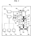
- FIG. 1 is a diagram illustrating a configuration of a vehicle 100 provided with a vehicle control device (controller) 111 according to a first embodiment of the present invention.
- An engine 101 is mounted on the vehicle 100.
- the driving force generated by the engine 101 is transmitted to wheels 104 connected via a differential mechanism 103 through a transmission 102, thereby causing the vehicle 100 to run.
- the wheels 104 are provided with a brake mechanism 115.
- the braking force is changed by a pressing amount of a brake pad in the brake mechanism 115, and the speed of the vehicle 100 is adjusted.
- the transmission 102 includes a torque converter 116, a transmission oil pump 117, a transmission mechanism 118, and a clutch mechanism 119.
- the clutch mechanism 119 can transmit and cut off power from the engine 101 to the wheels 104.
- the transmission oil pump 117 is driven via an oil pump driving chain 120.
- the transmission mechanism 118 is not limited to a stepped transmission, but may be a continuously variable transmission in which a belt or a chain and a pulley are combined with each other.
- the clutch mechanism 119 may be provided between the oil pump driving chain 120 and the transmission mechanism 118, without being limited to be disposed between the transmission mechanism 118 and the differential mechanism 103.
- the transmission 102 includes a transmission input rotation speed sensor 122 which measures the rotation speed of the input shaft, and a transmission output rotation speed sensor 123 which measures the rotation speed of the output shaft.
- a transmission input rotation speed sensor 122 which measures the rotation speed of the input shaft
- a transmission output rotation speed sensor 123 which measures the rotation speed of the output shaft.
- a starter motor 105 is assembled to the engine 101 as a startup device.
- the starter motor 105 is driven by supplying the electric power from the battery 108, and the engine 101 also rotates in conjunction with the rotation of the starter motor 105.
- a motor having functions of a starter motor and a generator may be used as the engine startup device, without being limited to the starter motor 105.
- An engine rotation speed sensor 121 for detecting the rotation speed is attached to the engine 101.
- the engine 101 is started by driving the starter motor 105 to start the fuel supply and ignition when the engine rotation speed reaches a predetermined value or higher.
- a generator 106 is connected to the engine 101 via a drive belt 107.
- the generator 106 can generate electric power by being rotated in accordance with the rotation of the crankshaft.
- the generator 106 has a mechanism for varying the generated voltage by controlling the field current and can stop the power generation output.
- the electric power generated by the generator 106 is supplied to the battery 108, an in-vehicle electric component 109, and the controller 111.
- the in-vehicle electric component 109 includes an actuator (for example, a fuel supply device, and an ignition device) for operating the engine 101, a lighting device such as a headlight, a brake lamp, and a turn signal indicator, and an air conditioner such as a blower fan and a heater.
- the controller 111 controls the in-vehicle electric component 109 including these components.
- An accelerator pedal depression amount sensor 112 for detecting the depression amount of the accelerator pedal, a brake pedal depression amount sensor 113 for detecting the depression amount of the brake pedal, and a vehicle speed sensor 114 for detecting the speed of the vehicle are connected to the controller 111, and information detected by these sensors is input to the controller 111.
- the brake mechanism 115 may be provided not only with a mechanism for controlling the braking force by changing a pressing amount of the brake pad in accordance with the brake pedal depression amount of the driver, but also an electric actuator mechanism capable of changing the pressing amount by a command value from the controller 111.
- FIG. 2 is a flowchart illustrating a process in which the controller 111 controls the operation of the engine 101.
- the controller 111 controls the operation of the engine 101, for example, by periodically executing the flowchart. Each step of FIG. 2 will be described below.
- the controller 111 determines whether the clutch mechanism 119 is disengaged or engaged. Specifically, the state of the clutch mechanism 119 is determined, using methods such as, (a) a method for measuring the engagement pressure of the clutch mechanism 119 using the oil pressure sensor, and (b) a method for determining that the clutch mechanism 119 is in the disengaged state when there is a difference in the rotation speeds between the transmission output rotation speed sensor 123 and the vehicle speed.
- the process proceeds to S202, and when it is determined that the clutch mechanism 119 is in the engaged state, the present flowchart is ended.
- the controller 111 calculates a target driving force Ft in accordance with the vehicle speed detected by the vehicle speed sensor 114 and the accelerator opening degree detected by the accelerator pedal depression amount sensor 112. Details of this step will be described again with reference to FIG. 3 which will be described later.
- the controller 111 calculates the target engine output P t_e in accordance with the following formula (1).
- F t is a target driving force
- M is a vehicle weight
- C d is an air resistance coefficient
- S is a front projection area of the vehicle
- V is a vehicle speed
- ⁇ is a rolling resistance coefficient
- g is a gravitational acceleration
- ⁇ is a road surface gradient
- the controller 111 calculates the target engine rotation speed on the basis of the target engine output. Details of this step will be described with reference to FIGS. 4 to 5 which will be described later.
- the controller 111 calculates the target transmission ratio on the basis of the target engine output, the vehicle speed, the accelerator opening degree, and the transmission output rotation speed. Details of this step will be described with reference to FIG. 6 which will be described later.
- the controller 111 determines whether or not the actual transmission ratio has reached the target transmission ratio. If the target transmission ratio is different from the actual transmission ratio, the process proceeds to S207. If the target transmission ratio becomes equal to the actual transmission ratio, the process proceeds to S210. This step is to drive the engine at an operating point with high engine efficiency by first controlling the transmission ratio before controlling the engine rotation speed.
- the controller 111 determines whether or not the engine 101 is in a stopped state on the basis of the detection result of the engine rotation speed sensor 121. More specifically, by shifting from a state in which the fuel supply to the engine 101 is cut off to a state for supplying fuel again, when reaching the minimum engine rotation speed (400 to 500 r/min) at which engine idling can be resumed, it is determined that the engine 101 is operating. Otherwise, it is determined that the engine 101 is stopped. If the engine 101 is stopped, the process proceeds to step S208, and otherwise, the process skips to step S209.
- the controller 111 performs cranking until the engine rotation speed reaches a predetermined rotation speed by the engine startup device, and performs the fuel supply and ignition after predetermined conditions are satisfied. As a result, the engine 101 is restored to the above idling rotation speed or higher.
- the controller 111 supplies a predetermined hydraulic pressure to the transmission mechanism 118, thereby controlling the transmission mechanism 118 to achieve the target transmission ratio.
- the controller 111 controls throttle, ignition timing, and the like so as to raise the engine rotation speed to the transmission input rotation speed.
- step S208 When the actual transmission ratio reaches the target transmission ratio in step S208 and then the process proceeds to step S210, there is a possibility that the timing of controlling the engine rotation speed will be delayed, which leads to an acceleration delay. Therefore, a suitable means detects that the time, at which the actual transmission ratio reaches the target transmission ratio, falls within a predetermined value, and the process proceeds from step S208 to S210 at that timing.
- the controller 111 determines whether or not the engine rotation speed and the transmission input rotation speed are synchronized (that is, the difference between the engine rotation speed and the transmission input rotation speed becomes equal to or less than a predetermined value) . If the engine rotation speed and the transmission input rotation speed are synchronized, the process proceeds to step S212, and if the engine rotation speed and the transmission input rotation speed are not synchronized, the present flowchart is ended.
- the controller 111 gradually supplies a predetermined hydraulic pressure to the clutch mechanism 119, thereby smoothly engaging the clutch.
- FIG. 3 is a diagram illustrating the details of step S202 .
- the controller 111 executes a control calculation so that the target driving force increases as the accelerator opening degree increases.
- the relation between the accelerator opening degree/the vehicle speed/the target driving force is, for example, as exemplified in FIG. 3 .
- the relation between these parameters exemplified in FIG. 3 can be stored in advance in a suitable storage device, as a parameter such as a control map.
- FIG. 4 is an exemplary view illustrating an efficiency curve (solid line) and an equal output curve (broken line) of the engine.
- a horizontal axis represents the engine rotation speed
- a vertical axis represents the engine torque.
- the engine efficiency curves (E1, E2, and E3) the engine efficiency is generally the highest at the center of the ellipse, and the farther away from the center is, the lower efficiency is.
- one obtained by connecting the most efficient points among the equal output curves (P1, P2, and P3) of the engine is represented as an optimum fuel efficiency curve.
- FIG. 5 illustrates an example of a control map 501 used when the controller 111 obtains the target engine rotation speed based on the target engine output. Since the engine efficiency characteristics differ depending on the type of the engine, the relation between the target engine output and the optimum target engine rotation speed corresponding thereto (relation as illustrated in FIG. 4 ) is previously derived, and the control map 501 with the relation described thereon can be stored in a suitable storage device in advance. The controller 111 can calculate the target engine rotation speed, using the control map 501.
- FIG. 6 is a diagram illustrating the processing procedure in step S205.
- the controller 111 calculates the target transmission input rotation speed on the basis of the vehicle speed and the accelerator opening degree. For example, the relation between the target transmission input rotation speed/the vehicle speed/the accelerator opening degree can be stored in a suitable storage device in advance as the target transmission input rotation speed map 601 after being calculated.
- the target transmission input rotation speed map 601 is set so that the target transmission input rotation speed increases as the accelerator opening degree increases.
- the controller 111 can calculate the target transmission input rotation speed, using the target transmission input rotation speed map 601.
- the controller 111 uses the larger one between the target engine rotation speed calculated in step S204 and the target transmission input rotation speed calculated on the basis of the target transmission input rotation speed map 601, as the final target transmission input rotation speed which is input to the transmission 102. As a result, when the target output is large, since the small transmission ratio is not selected, the fuel efficiency can be improved, while ensuring the acceleration performance.
- the controller 111 calculates the target transmission ratio, by dividing the finally used target transmission input rotation speed by the transmission output rotation speed detected by the transmission output rotation speed sensor 123.
- FIG. 7 is a time chart illustrating the change with time of each parameter in the first embodiment.
- the change with time of each parameter obtained by the conventional control is indicated by a dotted line
- the change with time of each parameter obtained by the control of the first embodiment is indicated by a solid line.
- the controller 111 When the controller 111 detects that the accelerator enters an OFF state, the controller 111 disengages the clutch.
- the engine rotation speed gradually decreases to 0, and the transmission ratio also changes from a low level to a high level.
- the operation after the accelerator enters the ON state differs between the conventional control and the control in the first embodiment.
- the transmission ratio is maintained until the clutch is engaged after the accelerator enters the ON state. After the clutch is engaged, the transmission ratio is controlled until the target rotation speed is obtained. Therefore, since the engine is driven at the rotation speed with the low engine efficiency, the fuel economy deteriorates.
- the transmission ratio is shifted to a low level (see S206 to S209), and the clutch is engaged after shifting the transmission input rotation speed to the target rotation speed (see S210 to S212).
- the controller 111 controls the transmission ratio up to the target transmission ratio before increasing the engine rotation speed, then controls the engine rotation speed, and then engages the clutch. This makes it possible to drive the engine 101 at a rotation speed with high engine efficiency, thereby improving the fuel economy.
- FIG. 8 is a time chart illustrating the automatic acceleration/deceleration control in which the sailing stop and acceleration are repeated within the prescribed vehicle speed range.
- a controller 111 accelerates the vehicle 100 until the vehicle speed reaches the set upper limit vehicle speed.
- the clutch is disengaged and an engine 101 is stopped, and the sailing stop is performed. Thereafter, when the vehicle 100 reaches the lower limit vehicle speed, the engine 101 is restarted, the clutch is engaged, and then the vehicle 100 is accelerated. Thereafter, the same control procedure is repeated.
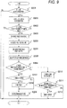
- FIG. 9 is a flowchart illustrating a process in which the controller 111 controls the operation of the engine 101 in the second embodiment.
- FIG. 8 a flowchart in which the control procedure of the first embodiment is applied to the automatic acceleration/deceleration control in which the sailing stop and acceleration are repeated within the prescribed vehicle speed range will be described. The same steps as those in FIG. 2 will not be described, and additionally changed steps will be described.
- the controller 111 performs this step after step S201.
- the controller 111 estimates the time T a until the next reacceleration of the vehicle 100 is started at the time when the vehicle is running in the clutch disengaging state.
- the estimated time T a until reacceleration during running in the clutch disengaging state can be calculated by the following formula (3) .
- V 0 represents the current vehicle speed
- V represents the vehicle speed at which the acceleration starts.
- T a V 0 ⁇ V ⁇ s
- the predetermined value to be compared with T a is, for example, a value obtained by adding the engine startup time Te and the shift delay time Tt of the transmission 102.
- the larger one of Te and Tt may be set as a predetermined value.
- the engine startup time Te is defined as a time until, for example, the engine is cranked and the engine rotation speed reaches a value larger than the idling rotation speed.
- the controller 111 performs the following process.
- the controller 111 calculates a vehicle speed difference between the upper limit vehicle speed and the actual vehicle speed, and sets the target acceleration ⁇ t to be larger as the vehicle speed difference is larger.
- the maximum value of the target acceleration ⁇ t is a value regulated by laws and regulations.
- the controller 111 calculates the target driving force F a at the time of acceleration of the automatic acceleration/deceleration control in accordance with the following formula (4).
- ⁇ t represents the target acceleration at the time of automatic acceleration/deceleration
- M represents the vehicle weight.
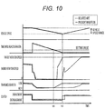
- FIG. 10 is a time chart illustrating the change with time of each parameter in the second embodiment.
- the change with time of each parameter obtained by the conventional control is indicated by a dotted line
- the change with time of each parameter obtained by the control of the second embodiment is indicated by a solid line.
- the engine 101 is started at the time t 2 at which acceleration starts from the sailing stop state, and after the clutch engagement, the transmission ratio is controlled so that the engine rotation speed reaches the target value.
- the transmission ratio is controlled in the engine stop state, the clutch is engaged after the engine 101 is started, and the acceleration control is performed. Therefore, as compared with the conventional control, since the engine 101 is accelerated at an operating point with high engine efficiency, the fuel economy can be improved.
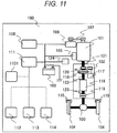
- FIG. 11 is a diagram illustrating a configuration of a vehicle 100 provided with a controller 111 according to a third embodiment of the present invention.
- the vehicle 100 includes a front situation recognition sensor 1101 in addition to the configuration described in the first embodiment.
- the front situation recognition sensor 1101 includes at least one means for detecting a front situation of the vehicle 100, such as a navigation system, a camera, a radar, an inter-vehicle communication or a road-to-vehicle communication module.
- the controller 111 can acquire the inter-vehicle distance or the relative speed (the preceding vehicle speed - own vehicle speed) between the vehicle 100 and the preceding vehicle, on the basis of the detection result of the front situation recognition sensor 1101.
- FIG. 12 is a diagram illustrating a procedure of calculating the target driving force in the constant speed running state by the controller 111 in the third embodiment.
- the controller 111 calculates the target acceleration ⁇ f using the inter-vehicle distance and the relative speed to the preceding vehicle as input parameters.
- the controller 111 further calculates the target acceleration on the basis of the difference between the set vehicle speed and the actual vehicle speed in the constant speed running state as input parameters.
- the controller 111 compares the two calculated target accelerations and adopts the smaller one as the target acceleration ⁇ t .
- the controller 111 obtains the target driving force F a by multiplying the target acceleration ⁇ t by the vehicle weight M.
- the constant speed running control is executed, and when the preceding vehicle is detected, the automatic acceleration/deceleration control can be executed to prevent collision.
- each input parameter and the target acceleration can be stored in advance in a suitable memory device, for example, in the form of a control map or the like.
- the control map is set in advance so that the target acceleration ⁇ f increases as the inter-vehicle distance increases and as the relative speed increases (that is, the preceding vehicle speed becomes larger than the own vehicle speed).
- FIG. 13 is a flowchart illustrating a process in which a controller 111 controls the operation of an engine 101 in a vehicle 100 according to a fourth embodiment of the present invention.
- the vehicle 100 has the same configuration as that of the third embodiment. Since other configurations are the same as those of the third embodiment, differences will mainly be described below.
- the controller 111 executes this step and the following step S1302 in place of step S901.
- the controller 111 On the basis of information on the preceding vehicle at time t (position X p (t), and velocity V p (t)), the controller 111 first assumes that the preceding person performs equal acceleration motion, and calculates the prediction values of each of the position and the speed of the preceding vehicle at time t+t n (0 ⁇ t n ⁇ t max ) in accordance with the following formulas (5) and (6).
- the controller 111 calculates prediction values of each of the position and velocity of the own vehicle at the time t+1 in accordance with the following formulas (7) and (8). It is also possible to calculate sequentially the prediction values also after time t+1.
- V t + 1 V t + ⁇ f t
- X t + 1 X t + V t + 1
- the controller 111 calculates the prediction value D(t) of the inter-vehicle distance and the prediction value V r (t) of the relative speed at the time t in accordance with the following formulas (9) and (10).
- the time subsequent to the time t can also be similarly calculated.
- V r t V p t ⁇ V t
- D t X p t ⁇ X t
- the controller 111 calculates the target acceleration prediction value ⁇ f (t) of the own vehicle in accordance with the procedure described in FIG. 12 . It is also possible to similarly calculate the target acceleration prediction values ⁇ f (t+1) to ⁇ f (t+t n ) at the times t+1 to t+t n .
- the controller 111 calculates the target driving force prediction values F a (t), ..., F a (t+t n ) on the basis of the product of the target acceleration prediction values ⁇ f (t), ..., ⁇ f (t+t n ) and the vehicle weight M.
- the controller 111 adopts the time from the current time t to the time until one of the target driving force prediction values F a (t), ..., F a (t+t n ) becomes greater than 0, as T a in step S901.
- the controller 111 performs this step and the following step S1304.
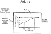
- the controller 111 calculates the target engine rotation speed on the basis of the average value of the target engine output prediction values. The processing image of this step will be described with reference to FIG. 14 .
- FIG. 14 is a diagram illustrating a processing image in step S1304.
- the controller 111 calculates the average value P e_ave of the target engine output prediction values Pe(t) to P e (t+t n ) at each of the times t to t+t n .
- the controller 111 calculates the target engine rotation speed, by applying the average value P e_ave of the target engine output prediction value to the control map 501 described with reference to FIG. 5 . As a result, it is possible to suppress vertical fluctuation of the engine rotation speed or the like, and to reduce unpleasant feeling or the like given to the driver.
- control map is used as the means for calculating each parameter, but other means may be used as long as it defines the relations between the parameters .
- a function defining an equivalent relation can be used.
- each of the above-described configurations, functions, processing units, processing means, and the like may be achieved as hardware by designing part or all of them, for example, by an integrated circuit. Further, each of the above-described configurations, functions, and the like may be achieved as software when the processor interprets and executes a program that achieves each function. Information such as programs, tables, and files that achieve each function can be stored in a storage device such as a memory, a hard disk, and a solid state drive (SSD), and a storage medium such as an IC card, an SD card, and a DVD.
- SSD solid state drive
- each control process performed by the controller 111 can be achieved, when a control program is stored in advance in a storage device such as a memory included in the controller 111, and an operation device such as a central processing unit (CPU) included in the controller 111 executes the control program.
- a control program is stored in advance in a storage device such as a memory included in the controller 111
- an operation device such as a central processing unit (CPU) included in the controller 111 executes the control program.
- CPU central processing unit
Description
- The present invention relates to a vehicle control device.
- Recently, various techniques for improving the fuel economy of an engine equipped with an internal combustion engine have been developed.
PTL 1 discloses, as an object of "providing a vehicle control device capable of securing a long running time or a long running distance due to coasting in a running vehicle", a technique in which, "when a vehicle speed V of the vehicle is within a vehicle speed range determined by a lower limit side vehicle speed V0 and an upper limit side vehicle speed V1, if the vehicle speed V is equal to or higher than the vehicle speed V0, the vehicle control device stops an engine by fuel cut and disengages a clutch to cause the vehicle to run by coasting, if the vehicle speed V becomes lower than the vehicle speed V0, the vehicle control device starts the engine by fuel supply and engages the clutch to perform acceleration (constant speed free run) . When it is necessary to stop the vehicle, the vehicle control device stops the engine by fuel cut until the vehicle stops, disengages the clutch, and causes the vehicle to run by coasting (stop free run), and thereafter, engages the clutch to impart braking by the engine brake and the brake device. As a result, it is possible to ensure a long running time and a long running distance due to coasting and to improve fuel economy" (see abstract). - When the clutch is brought into an engaged state and the fuel supply to the engine is stopped and the vehicle is driven (hereinafter referred to as engine brake), the deceleration of the engine brake becomes an addition of engine loss (mechanical loss, intake loss, etc.) to the running resistance. On the other hand, when the vehicle is driven in a state in which the engine is stopped and the clutch is disengaged (also referred to as a stop free run in
PTL 1, hereinafter also referred to as "sailing stop"), since the deceleration of the sailing stop is only the running resistance, the deceleration of the sailing stop becomes smaller than the deceleration of the engine brake. - Therefore, in
PTL 1, when it is determined that there is a need to stop the vehicle and the distance up to the stop is equal to or larger than a predetermined value, first, the sailing stop is executed, and when the distance up to the stop becomes less than the predetermined value, the vehicle is decelerated with engine brake or brake (see paragraph 0066 or the like) . InPTL 1, it is intended to lengthen the engine stop time and improve fuel economy by the above-described operation. PTL 2 describes a vehicle control device configured for a sweep-up control to engage a clutch by concurrently with engaging the clutch increasing the rotational speed of an engine toward a target rotational speed. -
- PTL 1:
JP 2012-47148 A - PTL 2:
WO 2015/092518 A1 - According to
PTL 1, when the vehicle speed becomes lower than the lower limit vehicle speed, the engine is started, and when the clutch is in an engaged state and accelerated, a transmission ratio is controlled. As a result, it is intended to control the transmission ratio to drive the engine in a best fuel economy range of the engine. However, there is a certain degree of delay when controlling the transmission to a predetermined transmission ratio. Therefore, after starting the engine, the clutch is engaged, and until reaching the operating point with high engine efficiency, it is necessary to drive the engine at an operating point with low engine efficiency, and the fuel economy effect decreases accordingly. - The present invention has been made to solve the above problem, and an object thereof is to drive an engine at an operating point with high engine efficiency to improve fuel economy.
- A vehicle control device according to the present invention controls the transmission ratio before increasing the rotation speed of the engine, and then engages the clutch, in accordance with the appended
claim 1. - According to the vehicle control device of the present invention, the fuel economy can be improved by shortening the time until reaching the operating point with good engine efficiency.
-
- [
FIG. 1] FIG. 1 is a diagram illustrating a configuration of avehicle 100 provided with a vehicle control device (controller) 111 according to a first embodiment. - [
FIG. 2] FIG. 2 is a flowchart illustrating a process in which thecontroller 111 controls an operation of anengine 101. - [
FIG. 3] FIG. 3 is a diagram illustrating the details of step S202. - [
FIG. 4] FIG. 4 is an exemplary view illustrating an efficiency curve (solid line) and an equal output curve (broken line) of the engine. - [
FIG. 5] FIG. 5 is an example of acontrol map 501 used when thecontroller 111 obtains a target engine rotation speed based on a target engine output. - [
FIG. 6] FIG. 6 is a diagram illustrating a processing procedure in step S205. - [
FIG. 7] FIG. 7 is a time chart illustrating the change with time of each parameter in the first embodiment. - [
FIG. 8] FIG. 8 is a time chart illustrating an automatic acceleration/deceleration control in which sailing stop and acceleration are repeated within a prescribed vehicle speed range. - [
FIG. 9] FIG. 9 is a flowchart illustrating a process in which thecontroller 111 controls the operation of theengine 101 in a second embodiment. - [
FIG. 10] FIG. 10 is a time chart illustrating the change with time of each parameter in the second embodiment. - [
FIG. 11] FIG. 11 is a diagram illustrating a configuration of avehicle 100 provided with acontroller 111 according to a third embodiment. - [
FIG. 12] FIG. 12 is a diagram illustrating a procedure of calculating the target driving force in the constant speed running state by thecontroller 111 in the third embodiment. - [
FIG. 13] FIG. 13 is a flowchart illustrating a process in which thecontroller 111 controls the operation of theengine 101 in thevehicle 100 according to a fourth embodiment. - [
FIG. 14] FIG. 14 is a diagram illustrating a processing image in step S1304. -
FIG. 1 is a diagram illustrating a configuration of avehicle 100 provided with a vehicle control device (controller) 111 according to a first embodiment of the present invention. Anengine 101 is mounted on thevehicle 100. The driving force generated by theengine 101 is transmitted towheels 104 connected via adifferential mechanism 103 through atransmission 102, thereby causing thevehicle 100 to run. In order to decelerate thevehicle 100, thewheels 104 are provided with abrake mechanism 115. The braking force is changed by a pressing amount of a brake pad in thebrake mechanism 115, and the speed of thevehicle 100 is adjusted. - The
transmission 102 includes atorque converter 116, atransmission oil pump 117, atransmission mechanism 118, and aclutch mechanism 119. Theclutch mechanism 119 can transmit and cut off power from theengine 101 to thewheels 104. Thetransmission oil pump 117 is driven via an oilpump driving chain 120. Thetransmission mechanism 118 is not limited to a stepped transmission, but may be a continuously variable transmission in which a belt or a chain and a pulley are combined with each other. Theclutch mechanism 119 may be provided between the oilpump driving chain 120 and thetransmission mechanism 118, without being limited to be disposed between thetransmission mechanism 118 and thedifferential mechanism 103. Thetransmission 102 includes a transmission inputrotation speed sensor 122 which measures the rotation speed of the input shaft, and a transmission outputrotation speed sensor 123 which measures the rotation speed of the output shaft. When theengine 101 stops during a sailing stop or the like, since thetransmission oil pump 117 cannot be driven, the hydraulic pressure for maintaining the transmission ratio is insufficient. Therefore, in order to secure the hydraulic pressure of thetransmission 102 during stop of theengine 101, anelectric oil pump 124 for the transmission is provided. By supplying the electric power from abattery 108 to theelectric oil pump 124, a necessary hydraulic pressure is secured. - A
starter motor 105 is assembled to theengine 101 as a startup device. Thestarter motor 105 is driven by supplying the electric power from thebattery 108, and theengine 101 also rotates in conjunction with the rotation of thestarter motor 105. A motor having functions of a starter motor and a generator may be used as the engine startup device, without being limited to thestarter motor 105. An enginerotation speed sensor 121 for detecting the rotation speed is attached to theengine 101. Theengine 101 is started by driving thestarter motor 105 to start the fuel supply and ignition when the engine rotation speed reaches a predetermined value or higher. - A
generator 106 is connected to theengine 101 via adrive belt 107. Thegenerator 106 can generate electric power by being rotated in accordance with the rotation of the crankshaft. Thegenerator 106 has a mechanism for varying the generated voltage by controlling the field current and can stop the power generation output. The electric power generated by thegenerator 106 is supplied to thebattery 108, an in-vehicleelectric component 109, and thecontroller 111. The in-vehicleelectric component 109 includes an actuator (for example, a fuel supply device, and an ignition device) for operating theengine 101, a lighting device such as a headlight, a brake lamp, and a turn signal indicator, and an air conditioner such as a blower fan and a heater. Thecontroller 111 controls the in-vehicleelectric component 109 including these components. - An accelerator pedal
depression amount sensor 112 for detecting the depression amount of the accelerator pedal, a brake pedaldepression amount sensor 113 for detecting the depression amount of the brake pedal, and avehicle speed sensor 114 for detecting the speed of the vehicle are connected to thecontroller 111, and information detected by these sensors is input to thecontroller 111. - The
brake mechanism 115 may be provided not only with a mechanism for controlling the braking force by changing a pressing amount of the brake pad in accordance with the brake pedal depression amount of the driver, but also an electric actuator mechanism capable of changing the pressing amount by a command value from thecontroller 111. -
FIG. 2 is a flowchart illustrating a process in which thecontroller 111 controls the operation of theengine 101. Thecontroller 111 controls the operation of theengine 101, for example, by periodically executing the flowchart. Each step ofFIG. 2 will be described below. - The
controller 111 determines whether theclutch mechanism 119 is disengaged or engaged. Specifically, the state of theclutch mechanism 119 is determined, using methods such as, (a) a method for measuring the engagement pressure of theclutch mechanism 119 using the oil pressure sensor, and (b) a method for determining that theclutch mechanism 119 is in the disengaged state when there is a difference in the rotation speeds between the transmission outputrotation speed sensor 123 and the vehicle speed. When it is determined that theclutch mechanism 119 is in the disengaged state, the process proceeds to S202, and when it is determined that theclutch mechanism 119 is in the engaged state, the present flowchart is ended. - The
controller 111 calculates a target driving force Ft in accordance with the vehicle speed detected by thevehicle speed sensor 114 and the accelerator opening degree detected by the accelerator pedaldepression amount sensor 112. Details of this step will be described again with reference toFIG. 3 which will be described later. - The
controller 111 calculates the target engine output Pt_e in accordance with the following formula (1). In the formula, Ft is a target driving force, M is a vehicle weight, Cd is an air resistance coefficient, S is a front projection area of the vehicle, V is a vehicle speed, µ is a rolling resistance coefficient, g is a gravitational acceleration, and θ is a road surface gradient, respectively.
[Formula 1]
- The
controller 111 calculates the target engine rotation speed on the basis of the target engine output. Details of this step will be described with reference toFIGS. 4 to 5 which will be described later. - The
controller 111 calculates the target transmission ratio on the basis of the target engine output, the vehicle speed, the accelerator opening degree, and the transmission output rotation speed. Details of this step will be described with reference toFIG. 6 which will be described later. - The
controller 111 determines whether or not the actual transmission ratio has reached the target transmission ratio. If the target transmission ratio is different from the actual transmission ratio, the process proceeds to S207. If the target transmission ratio becomes equal to the actual transmission ratio, the process proceeds to S210. This step is to drive the engine at an operating point with high engine efficiency by first controlling the transmission ratio before controlling the engine rotation speed. - The
controller 111 determines whether or not theengine 101 is in a stopped state on the basis of the detection result of the enginerotation speed sensor 121. More specifically, by shifting from a state in which the fuel supply to theengine 101 is cut off to a state for supplying fuel again, when reaching the minimum engine rotation speed (400 to 500 r/min) at which engine idling can be resumed, it is determined that theengine 101 is operating. Otherwise, it is determined that theengine 101 is stopped. If theengine 101 is stopped, the process proceeds to step S208, and otherwise, the process skips to step S209. - The
controller 111 performs cranking until the engine rotation speed reaches a predetermined rotation speed by the engine startup device, and performs the fuel supply and ignition after predetermined conditions are satisfied. As a result, theengine 101 is restored to the above idling rotation speed or higher. - The
controller 111 supplies a predetermined hydraulic pressure to thetransmission mechanism 118, thereby controlling thetransmission mechanism 118 to achieve the target transmission ratio. - After the actual transmission ratio reaches the target transmission ratio, the
controller 111 controls throttle, ignition timing, and the like so as to raise the engine rotation speed to the transmission input rotation speed. - When the actual transmission ratio reaches the target transmission ratio in step S208 and then the process proceeds to step S210, there is a possibility that the timing of controlling the engine rotation speed will be delayed, which leads to an acceleration delay. Therefore, a suitable means detects that the time, at which the actual transmission ratio reaches the target transmission ratio, falls within a predetermined value, and the process proceeds from step S208 to S210 at that timing.
- The
controller 111 determines whether or not the engine rotation speed and the transmission input rotation speed are synchronized (that is, the difference between the engine rotation speed and the transmission input rotation speed becomes equal to or less than a predetermined value) . If the engine rotation speed and the transmission input rotation speed are synchronized, the process proceeds to step S212, and if the engine rotation speed and the transmission input rotation speed are not synchronized, the present flowchart is ended. - The
controller 111 gradually supplies a predetermined hydraulic pressure to theclutch mechanism 119, thereby smoothly engaging the clutch. -
FIG. 3 is a diagram illustrating the details of step S202 . Thecontroller 111 executes a control calculation so that the target driving force increases as the accelerator opening degree increases. The relation between the accelerator opening degree/the vehicle speed/the target driving force is, for example, as exemplified inFIG. 3 . The relation between these parameters exemplified inFIG. 3 can be stored in advance in a suitable storage device, as a parameter such as a control map. -
FIG. 4 is an exemplary view illustrating an efficiency curve (solid line) and an equal output curve (broken line) of the engine. InFIG. 4 , a horizontal axis represents the engine rotation speed, and a vertical axis represents the engine torque. As illustrated by the engine efficiency curves (E1, E2, and E3), the engine efficiency is generally the highest at the center of the ellipse, and the farther away from the center is, the lower efficiency is. InFIG. 4 , one obtained by connecting the most efficient points among the equal output curves (P1, P2, and P3) of the engine is represented as an optimum fuel efficiency curve. - As illustrated in
FIG. 4 , in order to efficiently operate the engine, while obtaining a certain target engine output, it is necessary to control the engine to obtain the optimum engine rotation speed corresponding to the target engine output. For example, when the target engine output is P1, it is necessary to control the engine with R1 as the target engine rotation speed. -
FIG. 5 illustrates an example of acontrol map 501 used when thecontroller 111 obtains the target engine rotation speed based on the target engine output. Since the engine efficiency characteristics differ depending on the type of the engine, the relation between the target engine output and the optimum target engine rotation speed corresponding thereto (relation as illustrated inFIG. 4 ) is previously derived, and thecontrol map 501 with the relation described thereon can be stored in a suitable storage device in advance. Thecontroller 111 can calculate the target engine rotation speed, using thecontrol map 501. -
FIG. 6 is a diagram illustrating the processing procedure in step S205. Thecontroller 111 calculates the target transmission input rotation speed on the basis of the vehicle speed and the accelerator opening degree. For example, the relation between the target transmission input rotation speed/the vehicle speed/the accelerator opening degree can be stored in a suitable storage device in advance as the target transmission inputrotation speed map 601 after being calculated. The target transmission inputrotation speed map 601 is set so that the target transmission input rotation speed increases as the accelerator opening degree increases. Thecontroller 111 can calculate the target transmission input rotation speed, using the target transmission inputrotation speed map 601. - The
controller 111 uses the larger one between the target engine rotation speed calculated in step S204 and the target transmission input rotation speed calculated on the basis of the target transmission inputrotation speed map 601, as the final target transmission input rotation speed which is input to thetransmission 102. As a result, when the target output is large, since the small transmission ratio is not selected, the fuel efficiency can be improved, while ensuring the acceleration performance. - The
controller 111 calculates the target transmission ratio, by dividing the finally used target transmission input rotation speed by the transmission output rotation speed detected by the transmission outputrotation speed sensor 123. -
FIG. 7 is a time chart illustrating the change with time of each parameter in the first embodiment. InFIG. 7 , the change with time of each parameter obtained by the conventional control is indicated by a dotted line, and the change with time of each parameter obtained by the control of the first embodiment is indicated by a solid line. - When the
controller 111 detects that the accelerator enters an OFF state, thecontroller 111 disengages the clutch. The engine rotation speed gradually decreases to 0, and the transmission ratio also changes from a low level to a high level. The operation after the accelerator enters the ON state differs between the conventional control and the control in the first embodiment. - In the conventional control, the transmission ratio is maintained until the clutch is engaged after the accelerator enters the ON state. After the clutch is engaged, the transmission ratio is controlled until the target rotation speed is obtained. Therefore, since the engine is driven at the rotation speed with the low engine efficiency, the fuel economy deteriorates.
- In the control according to the first embodiment, when the accelerator enters the ON state, the transmission ratio is shifted to a low level (see S206 to S209), and the clutch is engaged after shifting the transmission input rotation speed to the target rotation speed (see S210 to S212). Thus, since the
engine 101 is driven at the rotation speed with high engine efficiency, the fuel economy can be improved. - The
controller 111 according to the first embodiment controls the transmission ratio up to the target transmission ratio before increasing the engine rotation speed, then controls the engine rotation speed, and then engages the clutch. This makes it possible to drive theengine 101 at a rotation speed with high engine efficiency, thereby improving the fuel economy. - In the second embodiment of the present invention, an example in which the control method described in the first embodiment is applied to the automatic acceleration/deceleration control of repeating the sailing stop and acceleration within a preset vehicle speed range will be described. Since a
vehicle 100 and its constituent elements are the same as those of the first embodiment, the differences will be mainly described below. -
FIG. 8 is a time chart illustrating the automatic acceleration/deceleration control in which the sailing stop and acceleration are repeated within the prescribed vehicle speed range. Acontroller 111 accelerates thevehicle 100 until the vehicle speed reaches the set upper limit vehicle speed. When thevehicle 100 reaches the upper limit vehicle speed, the clutch is disengaged and anengine 101 is stopped, and the sailing stop is performed. Thereafter, when thevehicle 100 reaches the lower limit vehicle speed, theengine 101 is restarted, the clutch is engaged, and then thevehicle 100 is accelerated. Thereafter, the same control procedure is repeated. -
FIG. 9 is a flowchart illustrating a process in which thecontroller 111 controls the operation of theengine 101 in the second embodiment. Here, as illustrated inFIG. 8 , a flowchart in which the control procedure of the first embodiment is applied to the automatic acceleration/deceleration control in which the sailing stop and acceleration are repeated within the prescribed vehicle speed range will be described. The same steps as those inFIG. 2 will not be described, and additionally changed steps will be described. - The
controller 111 performs this step after step S201. Thecontroller 111 estimates the time Ta until the next reacceleration of thevehicle 100 is started at the time when the vehicle is running in the clutch disengaging state. First, the vehicle acceleration αs in the clutch disengaging state is calculated in accordance with the following formula (2).
[Formula 2]
- When the
vehicle 100 is running within the prescribed vehicle speed range, the estimated time Ta until reacceleration during running in the clutch disengaging state can be calculated by the following formula (3) . In the formula, V0 represents the current vehicle speed, and V represents the vehicle speed at which the acceleration starts.
[Formula 3]
- If the time Ta until the reacceleration is within the predetermined value, the
controller 111 proceeds to step S903. Otherwise, thecontroller 111 continues the sailing stop by ending this flowchart. The predetermined value to be compared with Ta is, for example, a value obtained by adding the engine startup time Te and the shift delay time Tt of thetransmission 102. Alternatively, the larger one of Te and Tt may be set as a predetermined value. The engine startup time Te is defined as a time until, for example, the engine is cranked and the engine rotation speed reaches a value larger than the idling rotation speed. - In addition to the process described in step S202, the
controller 111 performs the following process. Thecontroller 111 calculates a vehicle speed difference between the upper limit vehicle speed and the actual vehicle speed, and sets the target acceleration αt to be larger as the vehicle speed difference is larger. The maximum value of the target acceleration αt is a value regulated by laws and regulations. Thecontroller 111 calculates the target driving force Fa at the time of acceleration of the automatic acceleration/deceleration control in accordance with the following formula (4). In formula (4), αt represents the target acceleration at the time of automatic acceleration/deceleration, and M represents the vehicle weight. Thecontroller 111 compares the calculated target driving force Fa with the target driving force Ft calculated in accordance with the step S202, and adopts the larger one as the target driving force. In step S203 and subsequent steps, the target driving force that is finally adopted is used.
[Formula 4]
-
FIG. 10 is a time chart illustrating the change with time of each parameter in the second embodiment. InFIG. 10 , the change with time of each parameter obtained by the conventional control is indicated by a dotted line, and the change with time of each parameter obtained by the control of the second embodiment is indicated by a solid line. - In the conventional control, the
engine 101 is started at the time t2 at which acceleration starts from the sailing stop state, and after the clutch engagement, the transmission ratio is controlled so that the engine rotation speed reaches the target value. - In the control according to the second embodiment, at the time t1 when the time until the start of the reacceleration becomes equal to or less than the predetermined value, the transmission ratio is controlled in the engine stop state, the clutch is engaged after the
engine 101 is started, and the acceleration control is performed. Therefore, as compared with the conventional control, since theengine 101 is accelerated at an operating point with high engine efficiency, the fuel economy can be improved. -
FIG. 11 is a diagram illustrating a configuration of avehicle 100 provided with acontroller 111 according to a third embodiment of the present invention. In the third embodiment, thevehicle 100 includes a frontsituation recognition sensor 1101 in addition to the configuration described in the first embodiment. The frontsituation recognition sensor 1101 includes at least one means for detecting a front situation of thevehicle 100, such as a navigation system, a camera, a radar, an inter-vehicle communication or a road-to-vehicle communication module. Thecontroller 111 can acquire the inter-vehicle distance or the relative speed (the preceding vehicle speed - own vehicle speed) between thevehicle 100 and the preceding vehicle, on the basis of the detection result of the frontsituation recognition sensor 1101. -
FIG. 12 is a diagram illustrating a procedure of calculating the target driving force in the constant speed running state by thecontroller 111 in the third embodiment. Thecontroller 111 calculates the target acceleration αf using the inter-vehicle distance and the relative speed to the preceding vehicle as input parameters. Thecontroller 111 further calculates the target acceleration on the basis of the difference between the set vehicle speed and the actual vehicle speed in the constant speed running state as input parameters. - The
controller 111 compares the two calculated target accelerations and adopts the smaller one as the target acceleration αt. Thecontroller 111 obtains the target driving force Fa by multiplying the target acceleration αt by the vehicle weight M. As a result, when the preceding vehicle is not detected, the constant speed running control is executed, and when the preceding vehicle is detected, the automatic acceleration/deceleration control can be executed to prevent collision. - The correspondence relation between each input parameter and the target acceleration can be stored in advance in a suitable memory device, for example, in the form of a control map or the like. The control map is set in advance so that the target acceleration αf increases as the inter-vehicle distance increases and as the relative speed increases (that is, the preceding vehicle speed becomes larger than the own vehicle speed).
-
FIG. 13 is a flowchart illustrating a process in which acontroller 111 controls the operation of anengine 101 in avehicle 100 according to a fourth embodiment of the present invention. In the fourth embodiment, thevehicle 100 has the same configuration as that of the third embodiment. Since other configurations are the same as those of the third embodiment, differences will mainly be described below. - The
controller 111 executes this step and the following step S1302 in place of step S901. On the basis of information on the preceding vehicle at time t (position Xp(t), and velocity Vp(t)), thecontroller 111 first assumes that the preceding person performs equal acceleration motion, and calculates the prediction values of each of the position and the speed of the preceding vehicle at time t+tn (0 ≤ tn ≤ tmax) in accordance with the following formulas (5) and (6).
[Formula 5]
[Formula 6]
- Next, the
controller 111 calculates prediction values of each of the position and velocity of the own vehicle at the time t+1 in accordance with the following formulas (7) and (8). It is also possible to calculate sequentially the prediction values also aftertime t+ 1.
[Formula 7]
[Formula 8]
- On the basis of the position Xp(t) of the preceding vehicle, the speed Vp(t) of the preceding vehicle, the position X (t) of the own vehicle, and the speed V(t) of the own vehicle, the
controller 111 calculates the prediction value D(t) of the inter-vehicle distance and the prediction value Vr(t) of the relative speed at the time t in accordance with the following formulas (9) and (10). The time subsequent to the time t can also be similarly calculated.
[Formula 9]
[Formula 10]
- On the basis of the prediction value D(t) of the inter-vehicle distance and the prediction value Vr(t) of the relative speed, the
controller 111 calculates the target acceleration prediction value αf(t) of the own vehicle in accordance with the procedure described inFIG. 12 . It is also possible to similarly calculate the target acceleration prediction values αf(t+1) to αf(t+tn) at the times t+1 to t+tn. Thecontroller 111 calculates the target driving force prediction values Fa(t), ..., Fa(t+tn) on the basis of the product of the target acceleration prediction values αf(t), ..., αf(t+tn) and the vehicle weight M. - The
controller 111 adopts the time from the current time t to the time until one of the target driving force prediction values Fa(t), ..., Fa(t+tn) becomes greater than 0, as Ta in step S901. - Instead of steps S902 to S204 in
FIG. 9 , thecontroller 111 performs this step and the following step S1304. Thecontroller 111 calculates the target engine output prediction value Pe(t+tn) at the time t+tn in accordance with the following formula (11).
[Formula 11]
- The
controller 111 calculates the target engine rotation speed on the basis of the average value of the target engine output prediction values. The processing image of this step will be described with reference toFIG. 14 . -
FIG. 14 is a diagram illustrating a processing image in step S1304. Thecontroller 111 calculates the average value Pe_ave of the target engine output prediction values Pe(t) to Pe(t+tn) at each of the times t to t+tn. Thecontroller 111 calculates the target engine rotation speed, by applying the average value Pe_ave of the target engine output prediction value to thecontrol map 501 described with reference toFIG. 5 . As a result, it is possible to suppress vertical fluctuation of the engine rotation speed or the like, and to reduce unpleasant feeling or the like given to the driver. - In the above embodiments, the control map is used as the means for calculating each parameter, but other means may be used as long as it defines the relations between the parameters . For example, a function defining an equivalent relation can be used.
- Each of the above-described configurations, functions, processing units, processing means, and the like may be achieved as hardware by designing part or all of them, for example, by an integrated circuit. Further, each of the above-described configurations, functions, and the like may be achieved as software when the processor interprets and executes a program that achieves each function. Information such as programs, tables, and files that achieve each function can be stored in a storage device such as a memory, a hard disk, and a solid state drive (SSD), and a storage medium such as an IC card, an SD card, and a DVD.
- For example, each control process performed by the
controller 111 can be achieved, when a control program is stored in advance in a storage device such as a memory included in thecontroller 111, and an operation device such as a central processing unit (CPU) included in thecontroller 111 executes the control program. -
- 100
- vehicle
- 101
- engine
- 102
- transmission
- 103
- differential mechanism
- 104
- wheel
- 105
- starter motor
- 106
- generator
- 107
- drive belt
- 108
- battery
- 109
- in-vehicle electric component
- 111
- controller
- 112
- accelerator pedal depression amount sensor
- 113
- brake pedal depression amount sensor
- 114
- vehicle speed sensor
- 115
- brake mechanism
- 116
- torque converter
- 117
- transmission oil pump
- 118
- transmission mechanism
- 119
- clutch mechanism
- 120
- oil pump driving chain
- 121
- engine rotation speed sensor
- 122
- transmission input rotation speed sensor
- 123
- transmission output rotation speed sensor
- 124
- electric oil pump
- 1101
- front situation recognition sensor
Claims (7)
- A vehicle control device which controls an operation of a vehicle (100),
wherein, while the vehicle (100) is running in a cutoff state of a clutch (119) configured to connect and disconnect a power transmission between an engine (101) of the vehicle (100) and wheels (104) of the vehicle (100), before a rotation speed of the engine (101) is increased, a transmission ratio of a transmission (102) provided in the vehicle (100) is controlled, and thereafter, the clutch (119) is engaged,
wherein the vehicle control device controls the transmission ratio up to a target transmission ratio before increasing the engine rotation speed, then controls the engine rotation speed, and then engages the clutch (119), and wherein in case the vehicle control device detects a time, at which an actual transmission ratio reaches the target transmission ratio, falls within a predetermined value, the vehicle control device controls throttle and ignition timing, so as to raise the engine rotation speed to a transmission input rotation speed,
characterized in that
the vehicle control device calculates the target transmission ratio by dividing a maximum value of a target engine rotational speed and a target transmission input rotational speed by a transmission output rotational speed, wherein the target engine rotational speed is determined based on a target engine output and an optimal fuel economy curve and the target transmission input rotational speed is determined based on a vehicle speed and an accelerator opening degree. - The vehicle control device according to claim 1, wherein in a state in which the vehicle (100) runs with the clutch (119) cutoff and an operation amount of an accelerator pedal provided in the vehicle (100) is 0, the transmission ratio is controlled before increasing the rotation speed of the engine (101), and thereafter, the clutch (119) is engaged.
- The vehicle control device according to claim 1, wherein in a state in which the vehicle (100) runs with the clutch (119) cutoff and fuel injection to the engine (101) is stopped, the transmission ratio is controlled before increasing the rotation speed of the engine (101), and thereafter, the clutch (119) is engaged.
- The vehicle control device according to claim 1, wherein after the clutch (119) is engaged, the rotation speed of the engine (101) is increased.
- The vehicle control device according to claim 1,
wherein a target rotation speed of the engine (101) is calculated after shifting from a state in which the clutch (119) is cutoff to a state in which the clutch (119) is engaged, and
the transmission is controlled to obtain a transmission ratio corresponding to the speed of the vehicle (100) and the target rotation speed. - The vehicle control device according to claim 5,
wherein a target acceleration of the vehicle (100) is calculated after shifting from a state in which the clutch (119) is cutoff to a state in which the clutch (119) is engaged, and
the target rotation speed is calculated on the basis of the target acceleration. - The vehicle control device according to claim 1, wherein the engine (101) and the transmission (102) are controlled to repeat coasting running of the state in which the clutch (119) is cutoff and driving running in which the rotation speed of the engine (101) is increased.
Applications Claiming Priority (2)
| Application Number | Priority Date | Filing Date | Title |
|---|---|---|---|
| JP2015190625 | 2015-09-29 | ||
| PCT/JP2016/073034 WO2017056729A1 (en) | 2015-09-29 | 2016-08-05 | Vehicle control device |
Publications (3)
| Publication Number | Publication Date |
|---|---|
| EP3357773A1 EP3357773A1 (en) | 2018-08-08 |
| EP3357773A4 EP3357773A4 (en) | 2019-06-05 |
| EP3357773B1 true EP3357773B1 (en) | 2021-06-23 |
Family
ID=58423525
Family Applications (1)
| Application Number | Title | Priority Date | Filing Date |
|---|---|---|---|
| EP16850906.5A Active EP3357773B1 (en) | 2015-09-29 | 2016-08-05 | Vehicle control device |
Country Status (5)
| Country | Link |
|---|---|
| US (1) | US10696303B2 (en) |
| EP (1) | EP3357773B1 (en) |
| JP (1) | JPWO2017056729A1 (en) |
| CN (1) | CN108025735B (en) |
| WO (1) | WO2017056729A1 (en) |
Families Citing this family (7)
| Publication number | Priority date | Publication date | Assignee | Title |
|---|---|---|---|---|
| US10451022B2 (en) | 2016-11-02 | 2019-10-22 | Paccar Inc | Intermittent restart for automatic engine stop start system |
| US10487762B2 (en) * | 2017-09-26 | 2019-11-26 | Paccar Inc | Systems and methods for predictive and automatic engine stop-start control |
| EP3693238B1 (en) * | 2017-10-04 | 2023-04-19 | Nissan Motor Co., Ltd. | Vehicle control method and control device |
| WO2019073583A1 (en) * | 2017-10-12 | 2019-04-18 | 日産自動車株式会社 | Method and apparatus for controlling automated vehicle |
| US10946852B2 (en) * | 2018-09-26 | 2021-03-16 | Toyota Motor Engineering & Manufacturing North America, Inc. | Systems and methods for determining engine start time during predicted acceleration events |
| SE543691C2 (en) * | 2019-10-02 | 2021-06-08 | Scania Cv Ab | Control device and method for starting a combustion engine during free-wheeling, a vehicle with such device, computer program for executing the method and computer readable medium containing the program |
| JP2022185413A (en) * | 2021-06-02 | 2022-12-14 | トヨタ自動車株式会社 | Controller of vehicle drive unit and control method |
Family Cites Families (9)
| Publication number | Priority date | Publication date | Assignee | Title |
|---|---|---|---|---|
| JP4462078B2 (en) * | 2005-03-17 | 2010-05-12 | 日産自動車株式会社 | Travel control device |
| US8187149B2 (en) * | 2009-07-16 | 2012-05-29 | GM Global Technology Operations LLC | Coasting control systems and methods for automatic transmission |
| JP2012047148A (en) * | 2010-08-30 | 2012-03-08 | Toyota Motor Corp | Control device of vehicle |
| JP5549563B2 (en) | 2010-12-01 | 2014-07-16 | トヨタ自動車株式会社 | Vehicle control device |
| JP5449240B2 (en) * | 2011-03-28 | 2014-03-19 | 本田技研工業株式会社 | Gear ratio control device and gear ratio control method |
| RU2014151053A (en) * | 2012-06-20 | 2016-08-10 | Тойота Дзидося Кабусики Кайся | VEHICLE MANAGEMENT SYSTEM |
| JP6064868B2 (en) * | 2013-11-08 | 2017-01-25 | トヨタ自動車株式会社 | Vehicle control device |
| KR101484228B1 (en) * | 2013-11-08 | 2015-01-16 | 현대자동차 주식회사 | Hybrid vehicle and control mehtod for the same |
| JP5954306B2 (en) | 2013-12-17 | 2016-07-20 | トヨタ自動車株式会社 | Vehicle control device |
-
2016
- 2016-08-05 CN CN201680043590.3A patent/CN108025735B/en active Active
- 2016-08-05 JP JP2017542992A patent/JPWO2017056729A1/en active Pending
- 2016-08-05 US US15/762,727 patent/US10696303B2/en active Active
- 2016-08-05 EP EP16850906.5A patent/EP3357773B1/en active Active
- 2016-08-05 WO PCT/JP2016/073034 patent/WO2017056729A1/en active Application Filing
Non-Patent Citations (1)
| Title |
|---|
| None * |
Also Published As
| Publication number | Publication date |
|---|---|
| EP3357773A1 (en) | 2018-08-08 |
| US10696303B2 (en) | 2020-06-30 |
| JPWO2017056729A1 (en) | 2018-02-22 |
| US20180257654A1 (en) | 2018-09-13 |
| CN108025735B (en) | 2022-09-27 |
| CN108025735A (en) | 2018-05-11 |
| EP3357773A4 (en) | 2019-06-05 |
| WO2017056729A1 (en) | 2017-04-06 |
Similar Documents
| Publication | Publication Date | Title |
|---|---|---|
| EP3357773B1 (en) | Vehicle control device | |
| KR101542988B1 (en) | Method for controlling hybrid electric vehicle using driving tendency of driver | |
| US9771058B2 (en) | Control method of hybrid vehicle | |
| EP3263941B1 (en) | Vehicle control device for controlling coasting travel of vehicle | |
| KR101526405B1 (en) | Method and apparatus for controlling engine starting while shifting of hybrid vehicle | |
| US20160023659A1 (en) | Vehicle controller | |
| JP2010179789A (en) | Controller for hybrid vehicle | |
| US10953879B2 (en) | Vehicle control apparatus | |
| WO2018168389A1 (en) | Vehicle control apparatus | |
| KR101724465B1 (en) | Method and apparatus for controlling engine start for hybrid electric vehicle | |
| EP3954917B1 (en) | Vehicle control device for controlling inertia operation of vehicle | |
| KR20160106421A (en) | Apparatus and method for controlling engine operating point of hybrid electric vehicle | |
| CN111194286B (en) | Vehicle control method and control device | |
| JP5185052B2 (en) | Vehicle control apparatus and control method | |
| EP3252347B1 (en) | Coast-stop control device | |
| KR101724505B1 (en) | Apparatus and method for shift control of vehicle | |
| KR101588793B1 (en) | Method for controlling hybrid electric vehicle using driving tendency of driver | |
| CN112776790A (en) | Power assembly system | |
| KR101588794B1 (en) | Method for controlling hybrid electric vehicle using driving tendency of driver | |
| KR20190072804A (en) | Method and apparatus for controlling mhsg of mild hybrid electric vehicle |
Legal Events
| Date | Code | Title | Description |
|---|---|---|---|
| STAA | Information on the status of an ep patent application or granted ep patent |
Free format text: STATUS: THE INTERNATIONAL PUBLICATION HAS BEEN MADE |
|
| PUAI | Public reference made under article 153(3) epc to a published international application that has entered the european phase |
Free format text: ORIGINAL CODE: 0009012 |
|
| STAA | Information on the status of an ep patent application or granted ep patent |
Free format text: STATUS: REQUEST FOR EXAMINATION WAS MADE |
|
| 17P | Request for examination filed |
Effective date: 20180328 |
|
| AK | Designated contracting states |
Kind code of ref document: A1 Designated state(s): AL AT BE BG CH CY CZ DE DK EE ES FI FR GB GR HR HU IE IS IT LI LT LU LV MC MK MT NL NO PL PT RO RS SE SI SK SM TR |
|
| AX | Request for extension of the european patent |
Extension state: BA ME |
|
| DAV | Request for validation of the european patent (deleted) | ||
| DAX | Request for extension of the european patent (deleted) | ||
| A4 | Supplementary search report drawn up and despatched |
Effective date: 20190507 |
|
| RIC1 | Information provided on ipc code assigned before grant |
Ipc: F16D 48/02 20060101ALI20190430BHEP Ipc: B60W 30/14 20060101ALI20190430BHEP Ipc: B60W 30/16 20120101ALI20190430BHEP Ipc: F02D 29/02 20060101ALI20190430BHEP Ipc: F16H 61/02 20060101ALI20190430BHEP Ipc: F16H 61/21 20060101ALI20190430BHEP Ipc: B60W 10/101 20120101ALI20190430BHEP Ipc: B60W 10/04 20060101ALI20190430BHEP Ipc: B60W 10/02 20060101AFI20190430BHEP Ipc: B60W 10/06 20060101ALI20190430BHEP Ipc: B60W 10/10 20120101ALI20190430BHEP Ipc: B60W 10/00 20060101ALI20190430BHEP Ipc: B60W 10/11 20120101ALI20190430BHEP |
|
| STAA | Information on the status of an ep patent application or granted ep patent |
Free format text: STATUS: EXAMINATION IS IN PROGRESS |
|
| 17Q | First examination report despatched |
Effective date: 20200511 |
|
| STAA | Information on the status of an ep patent application or granted ep patent |
Free format text: STATUS: EXAMINATION IS IN PROGRESS |
|
| GRAP | Despatch of communication of intention to grant a patent |
Free format text: ORIGINAL CODE: EPIDOSNIGR1 |
|
| STAA | Information on the status of an ep patent application or granted ep patent |
Free format text: STATUS: GRANT OF PATENT IS INTENDED |
|
| INTG | Intention to grant announced |
Effective date: 20210225 |
|
| GRAS | Grant fee paid |
Free format text: ORIGINAL CODE: EPIDOSNIGR3 |
|
| GRAA | (expected) grant |
Free format text: ORIGINAL CODE: 0009210 |
|
| STAA | Information on the status of an ep patent application or granted ep patent |
Free format text: STATUS: THE PATENT HAS BEEN GRANTED |
|
| AK | Designated contracting states |
Kind code of ref document: B1 Designated state(s): AL AT BE BG CH CY CZ DE DK EE ES FI FR GB GR HR HU IE IS IT LI LT LU LV MC MK MT NL NO PL PT RO RS SE SI SK SM TR |
|
| REG | Reference to a national code |
Ref country code: GB Ref legal event code: FG4D |
|
| REG | Reference to a national code |
Ref country code: CH Ref legal event code: EP |
|
| REG | Reference to a national code |
Ref country code: AT Ref legal event code: REF Ref document number: 1404064 Country of ref document: AT Kind code of ref document: T Effective date: 20210715 Ref country code: DE Ref legal event code: R096 Ref document number: 602016059781 Country of ref document: DE |
|
| REG | Reference to a national code |
Ref country code: IE Ref legal event code: FG4D |
|
| RAP4 | Party data changed (patent owner data changed or rights of a patent transferred) |
Owner name: HITACHI ASTEMO, LTD. |
|
| REG | Reference to a national code |
Ref country code: LT Ref legal event code: MG9D |
|
| REG | Reference to a national code |
Ref country code: DE Ref legal event code: R081 Ref document number: 602016059781 Country of ref document: DE Owner name: HITACHI ASTEMO, LTD., HITACHINAKA-SHI, JP Free format text: FORMER OWNER: HITACHI AUTOMOTIVE SYSTEMS, LTD., HITACHINAKA-SHI, IBARAKI, JP |
|
| PG25 | Lapsed in a contracting state [announced via postgrant information from national office to epo] |
Ref country code: FI Free format text: LAPSE BECAUSE OF FAILURE TO SUBMIT A TRANSLATION OF THE DESCRIPTION OR TO PAY THE FEE WITHIN THE PRESCRIBED TIME-LIMIT Effective date: 20210623 Ref country code: LT Free format text: LAPSE BECAUSE OF FAILURE TO SUBMIT A TRANSLATION OF THE DESCRIPTION OR TO PAY THE FEE WITHIN THE PRESCRIBED TIME-LIMIT Effective date: 20210623 Ref country code: HR Free format text: LAPSE BECAUSE OF FAILURE TO SUBMIT A TRANSLATION OF THE DESCRIPTION OR TO PAY THE FEE WITHIN THE PRESCRIBED TIME-LIMIT Effective date: 20210623 Ref country code: BG Free format text: LAPSE BECAUSE OF FAILURE TO SUBMIT A TRANSLATION OF THE DESCRIPTION OR TO PAY THE FEE WITHIN THE PRESCRIBED TIME-LIMIT Effective date: 20210923 |
|
| REG | Reference to a national code |
Ref country code: AT Ref legal event code: MK05 Ref document number: 1404064 Country of ref document: AT Kind code of ref document: T Effective date: 20210623 |
|
| PG25 | Lapsed in a contracting state [announced via postgrant information from national office to epo] |
Ref country code: SE Free format text: LAPSE BECAUSE OF FAILURE TO SUBMIT A TRANSLATION OF THE DESCRIPTION OR TO PAY THE FEE WITHIN THE PRESCRIBED TIME-LIMIT Effective date: 20210623 Ref country code: RS Free format text: LAPSE BECAUSE OF FAILURE TO SUBMIT A TRANSLATION OF THE DESCRIPTION OR TO PAY THE FEE WITHIN THE PRESCRIBED TIME-LIMIT Effective date: 20210623 Ref country code: NO Free format text: LAPSE BECAUSE OF FAILURE TO SUBMIT A TRANSLATION OF THE DESCRIPTION OR TO PAY THE FEE WITHIN THE PRESCRIBED TIME-LIMIT Effective date: 20210923 Ref country code: LV Free format text: LAPSE BECAUSE OF FAILURE TO SUBMIT A TRANSLATION OF THE DESCRIPTION OR TO PAY THE FEE WITHIN THE PRESCRIBED TIME-LIMIT Effective date: 20210623 Ref country code: GR Free format text: LAPSE BECAUSE OF FAILURE TO SUBMIT A TRANSLATION OF THE DESCRIPTION OR TO PAY THE FEE WITHIN THE PRESCRIBED TIME-LIMIT Effective date: 20210924 |
|
| REG | Reference to a national code |
Ref country code: NL Ref legal event code: MP Effective date: 20210623 |
|
| PG25 | Lapsed in a contracting state [announced via postgrant information from national office to epo] |
Ref country code: ES Free format text: LAPSE BECAUSE OF FAILURE TO SUBMIT A TRANSLATION OF THE DESCRIPTION OR TO PAY THE FEE WITHIN THE PRESCRIBED TIME-LIMIT Effective date: 20210623 Ref country code: RO Free format text: LAPSE BECAUSE OF FAILURE TO SUBMIT A TRANSLATION OF THE DESCRIPTION OR TO PAY THE FEE WITHIN THE PRESCRIBED TIME-LIMIT Effective date: 20210623 Ref country code: NL Free format text: LAPSE BECAUSE OF FAILURE TO SUBMIT A TRANSLATION OF THE DESCRIPTION OR TO PAY THE FEE WITHIN THE PRESCRIBED TIME-LIMIT Effective date: 20210623 Ref country code: PT Free format text: LAPSE BECAUSE OF FAILURE TO SUBMIT A TRANSLATION OF THE DESCRIPTION OR TO PAY THE FEE WITHIN THE PRESCRIBED TIME-LIMIT Effective date: 20211025 Ref country code: EE Free format text: LAPSE BECAUSE OF FAILURE TO SUBMIT A TRANSLATION OF THE DESCRIPTION OR TO PAY THE FEE WITHIN THE PRESCRIBED TIME-LIMIT Effective date: 20210623 Ref country code: CZ Free format text: LAPSE BECAUSE OF FAILURE TO SUBMIT A TRANSLATION OF THE DESCRIPTION OR TO PAY THE FEE WITHIN THE PRESCRIBED TIME-LIMIT Effective date: 20210623 Ref country code: AT Free format text: LAPSE BECAUSE OF FAILURE TO SUBMIT A TRANSLATION OF THE DESCRIPTION OR TO PAY THE FEE WITHIN THE PRESCRIBED TIME-LIMIT Effective date: 20210623 Ref country code: SM Free format text: LAPSE BECAUSE OF FAILURE TO SUBMIT A TRANSLATION OF THE DESCRIPTION OR TO PAY THE FEE WITHIN THE PRESCRIBED TIME-LIMIT Effective date: 20210623 Ref country code: SK Free format text: LAPSE BECAUSE OF FAILURE TO SUBMIT A TRANSLATION OF THE DESCRIPTION OR TO PAY THE FEE WITHIN THE PRESCRIBED TIME-LIMIT Effective date: 20210623 |
|
| PG25 | Lapsed in a contracting state [announced via postgrant information from national office to epo] |
Ref country code: PL Free format text: LAPSE BECAUSE OF FAILURE TO SUBMIT A TRANSLATION OF THE DESCRIPTION OR TO PAY THE FEE WITHIN THE PRESCRIBED TIME-LIMIT Effective date: 20210623 |
|
| REG | Reference to a national code |
Ref country code: DE Ref legal event code: R097 Ref document number: 602016059781 Country of ref document: DE |
|
| REG | Reference to a national code |
Ref country code: CH Ref legal event code: PL |
|
| PG25 | Lapsed in a contracting state [announced via postgrant information from national office to epo] |
Ref country code: MC Free format text: LAPSE BECAUSE OF FAILURE TO SUBMIT A TRANSLATION OF THE DESCRIPTION OR TO PAY THE FEE WITHIN THE PRESCRIBED TIME-LIMIT Effective date: 20210623 |
|
| REG | Reference to a national code |
Ref country code: BE Ref legal event code: MM Effective date: 20210831 |
|
| PG25 | Lapsed in a contracting state [announced via postgrant information from national office to epo] |
Ref country code: LI Free format text: LAPSE BECAUSE OF NON-PAYMENT OF DUE FEES Effective date: 20210831 Ref country code: DK Free format text: LAPSE BECAUSE OF FAILURE TO SUBMIT A TRANSLATION OF THE DESCRIPTION OR TO PAY THE FEE WITHIN THE PRESCRIBED TIME-LIMIT Effective date: 20210623 Ref country code: CH Free format text: LAPSE BECAUSE OF NON-PAYMENT OF DUE FEES Effective date: 20210831 |
|
| PLBE | No opposition filed within time limit |
Free format text: ORIGINAL CODE: 0009261 |
|
| STAA | Information on the status of an ep patent application or granted ep patent |
Free format text: STATUS: NO OPPOSITION FILED WITHIN TIME LIMIT |
|
| GBPC | Gb: european patent ceased through non-payment of renewal fee |
Effective date: 20210923 |
|
| 26N | No opposition filed |
Effective date: 20220324 |
|
| PG25 | Lapsed in a contracting state [announced via postgrant information from national office to epo] |
Ref country code: LU Free format text: LAPSE BECAUSE OF NON-PAYMENT OF DUE FEES Effective date: 20210805 Ref country code: AL Free format text: LAPSE BECAUSE OF FAILURE TO SUBMIT A TRANSLATION OF THE DESCRIPTION OR TO PAY THE FEE WITHIN THE PRESCRIBED TIME-LIMIT Effective date: 20210623 |
|
| PG25 | Lapsed in a contracting state [announced via postgrant information from national office to epo] |
Ref country code: IT Free format text: LAPSE BECAUSE OF FAILURE TO SUBMIT A TRANSLATION OF THE DESCRIPTION OR TO PAY THE FEE WITHIN THE PRESCRIBED TIME-LIMIT Effective date: 20210623 Ref country code: IE Free format text: LAPSE BECAUSE OF NON-PAYMENT OF DUE FEES Effective date: 20210805 Ref country code: GB Free format text: LAPSE BECAUSE OF NON-PAYMENT OF DUE FEES Effective date: 20210923 Ref country code: FR Free format text: LAPSE BECAUSE OF NON-PAYMENT OF DUE FEES Effective date: 20210823 Ref country code: BE Free format text: LAPSE BECAUSE OF NON-PAYMENT OF DUE FEES Effective date: 20210831 |
|
| PG25 | Lapsed in a contracting state [announced via postgrant information from national office to epo] |
Ref country code: CY Free format text: LAPSE BECAUSE OF FAILURE TO SUBMIT A TRANSLATION OF THE DESCRIPTION OR TO PAY THE FEE WITHIN THE PRESCRIBED TIME-LIMIT Effective date: 20210623 |
|
| PG25 | Lapsed in a contracting state [announced via postgrant information from national office to epo] |
Ref country code: HU Free format text: LAPSE BECAUSE OF FAILURE TO SUBMIT A TRANSLATION OF THE DESCRIPTION OR TO PAY THE FEE WITHIN THE PRESCRIBED TIME-LIMIT; INVALID AB INITIO Effective date: 20160805 |
|
| PGFP | Annual fee paid to national office [announced via postgrant information from national office to epo] |
Ref country code: DE Payment date: 20230627 Year of fee payment: 8 |