EP3357717B2 - Draw bar with an evaluation device - Google Patents
Draw bar with an evaluation device Download PDFInfo
- Publication number
- EP3357717B2 EP3357717B2 EP18150921.7A EP18150921A EP3357717B2 EP 3357717 B2 EP3357717 B2 EP 3357717B2 EP 18150921 A EP18150921 A EP 18150921A EP 3357717 B2 EP3357717 B2 EP 3357717B2
- Authority
- EP
- European Patent Office
- Prior art keywords
- trailer
- coupling
- force
- acceleration
- value
- Prior art date
- Legal status (The legal status is an assumption and is not a legal conclusion. Google has not performed a legal analysis and makes no representation as to the accuracy of the status listed.)
- Active
Links
- 238000011156 evaluation Methods 0.000 title claims description 120
- 230000001133 acceleration Effects 0.000 claims description 118
- 230000008878 coupling Effects 0.000 claims description 113
- 238000010168 coupling process Methods 0.000 claims description 113
- 238000005859 coupling reaction Methods 0.000 claims description 113
- 238000000034 method Methods 0.000 claims description 19
- 238000005259 measurement Methods 0.000 claims description 12
- 230000006835 compression Effects 0.000 claims description 4
- 238000007906 compression Methods 0.000 claims description 4
- 230000000630 rising effect Effects 0.000 claims 1
- 238000005096 rolling process Methods 0.000 description 8
- 230000008569 process Effects 0.000 description 5
- 230000006870 function Effects 0.000 description 4
- 230000005484 gravity Effects 0.000 description 4
- 238000012935 Averaging Methods 0.000 description 3
- 230000008901 benefit Effects 0.000 description 2
- 238000004364 calculation method Methods 0.000 description 2
- 238000001514 detection method Methods 0.000 description 2
- 238000010586 diagram Methods 0.000 description 2
- 230000007613 environmental effect Effects 0.000 description 2
- 238000000105 evaporative light scattering detection Methods 0.000 description 2
- 239000007789 gas Substances 0.000 description 2
- 238000005457 optimization Methods 0.000 description 2
- NAWXUBYGYWOOIX-SFHVURJKSA-N (2s)-2-[[4-[2-(2,4-diaminoquinazolin-6-yl)ethyl]benzoyl]amino]-4-methylidenepentanedioic acid Chemical compound C1=CC2=NC(N)=NC(N)=C2C=C1CCC1=CC=C(C(=O)N[C@@H](CC(=C)C(O)=O)C(O)=O)C=C1 NAWXUBYGYWOOIX-SFHVURJKSA-N 0.000 description 1
- 230000005540 biological transmission Effects 0.000 description 1
- 230000015572 biosynthetic process Effects 0.000 description 1
- 238000009529 body temperature measurement Methods 0.000 description 1
- 230000008859 change Effects 0.000 description 1
- 238000010276 construction Methods 0.000 description 1
- 238000012937 correction Methods 0.000 description 1
- 230000007423 decrease Effects 0.000 description 1
- 230000003247 decreasing effect Effects 0.000 description 1
- 230000000694 effects Effects 0.000 description 1
- 238000009434 installation Methods 0.000 description 1
- 238000005070 sampling Methods 0.000 description 1
- 230000008054 signal transmission Effects 0.000 description 1
- 230000006641 stabilisation Effects 0.000 description 1
- 230000001131 transforming effect Effects 0.000 description 1
Images

Classifications
-
- B—PERFORMING OPERATIONS; TRANSPORTING
- B60—VEHICLES IN GENERAL
- B60D—VEHICLE CONNECTIONS
- B60D1/00—Traction couplings; Hitches; Draw-gear; Towing devices
- B60D1/24—Traction couplings; Hitches; Draw-gear; Towing devices characterised by arrangements for particular functions
- B60D1/248—Traction couplings; Hitches; Draw-gear; Towing devices characterised by arrangements for particular functions for measuring, indicating or displaying the weight
-
- B—PERFORMING OPERATIONS; TRANSPORTING
- B60—VEHICLES IN GENERAL
- B60D—VEHICLE CONNECTIONS
- B60D1/00—Traction couplings; Hitches; Draw-gear; Towing devices
- B60D1/01—Traction couplings or hitches characterised by their type
- B60D1/06—Ball-and-socket hitches, e.g. constructional details, auxiliary devices, their arrangement on the vehicle
-
- B—PERFORMING OPERATIONS; TRANSPORTING
- B60—VEHICLES IN GENERAL
- B60D—VEHICLE CONNECTIONS
- B60D1/00—Traction couplings; Hitches; Draw-gear; Towing devices
- B60D1/58—Auxiliary devices
- B60D1/62—Auxiliary devices involving supply lines, electric circuits, or the like
Definitions
- the invention relates to a trailer coupling for a towing vehicle, according to the preamble of claim 1.
- a trailer coupling according to the technical teaching of claim 1 is provided.
- a method according to the technical teaching of claim 13 is also provided.
- a basic idea of the invention is that a force sensor, for example a force sensor dedicated to determining a deformation of the trailer coupling caused by tensile force, in particular of the dome carrier or the holder, is able to determine the trailer mass of the trailer based on the additional evaluation of the acceleration value to determine the trailer.
- a force can be determined as the product of mass and acceleration.
- the evaluation device is designed to take other factors into account, for example to evaluate and take into account friction values, inertial masses and the like.
- the basic concept according to the invention is based on deriving the mass of the trailer from the tractive force signal.
- the acceleration value is an acceleration value in the direction of travel or x-direction, but not a yaw rate acceleration value oriented, for example, around the vertical axis.
- the evaluation device expediently has a signal input for an acceleration signal.
- a signal input for an acceleration signal for example, there is a connection terminal, a socket or the like for the acceleration sensor.
- the acceleration sensor is a separate structural unit that can be connected to the evaluation device.
- the evaluation device prefferably has an acceleration sensor on board.
- the evaluation device has a temperature sensor so that it can carry out temperature compensation.
- the at least one force sensor can also serve to enable temperature compensation or to take a temperature into account:
- the temperature compensation can, for example, already be at the beginning of a measurement, that is, for example, according to the invention, the force signal generated by a respective force sensor still serves as a base value without a supporting load or tensile load, comparable, for example, to setting a tare on a scale.
- the at least one force sensor is calibrated, so to speak.
- the force sensor which is designed, for example, in the manner of a resistance measuring bridge, delivers, for example, a first force signal value at a first temperature and a second force signal value at a second temperature that is different from the first temperature.
- the respective force signal value is set as the base value and is therefore suitable, for example, as a correction value.
- the trailer coupling or its evaluation device also has an inclination sensor for determining an inclination angle and/or an interface for receiving an inclination angle value, for example from an inclination angle sensor present on board the towing vehicle.
- the angle of inclination corresponds to an inclined inclination of the motor vehicle or trailer consisting of motor vehicle and trailer, e.g. if the trailer is positioned downhill or uphill.
- the evaluation device or the method according to the invention are expediently designed to determine the trailer mass value as a function of the angle of inclination value and/or to eliminate the influence of the angle of inclination.
- the inclination sensor can also be formed by the acceleration sensor.
- the acceleration sensor which detects acceleration in three mutually angled axis directions (X-axis, Y-axis and Z-axis). If the motor vehicle is horizontal, the acceleration sensor only measures the force acting in the Z direction, namely the force of gravity or g, when the motor vehicle is stationary. When the motor vehicle is at an angle, however, the acceleration sensor also measures a portion of the gravitational force or gravitational acceleration g in the direction of the Acceleration sensor can be detected.
- an inclination angle compensation and/or the provision of an inclination sensor in particular an acceleration sensor that performs the function of an inclination sensor, and/or an interface for an inclination angle signal is of course also useful for a pure support load measurement, i.e. an independent idea according to the invention during a force measurement on a trailer coupling.
- the evaluation device expediently has a bus interface for a data bus of the towing vehicle.
- the interface includes a CAN interface, a LIN interface or the like.
- the acceleration value can be received via the bus interface.
- the towing vehicle has one or more acceleration sensors. It is also possible for the towing vehicle's electrical system to transmit acceleration values that were determined, for example, based on speed signals.
- the evaluation device is designed, for example, to transmit the mass value of the trailer via the bus interface. It goes without saying that instead of a bus interface, another data interface is also possible.
- the evaluation device is expediently also designed to determine a support load that is placed on the trailer coupling due to the trailer.
- the evaluation device takes into account a support load that the trailer exerts on the trailer coupling when determining the trailer mass value of the trailer.
- a variant can provide that the support load is determined externally and transmitted to the evaluation device via a corresponding data or signal input.
- the evaluation device itself is designed to determine the supporting load.
- the evaluation device determines the trailer mass value not when the towing vehicle is stationary, but rather when it is moving. For example, it is advantageous if the evaluation device determines the trailer mass value as a function of a driving speed of the towing vehicle.
- the evaluation device only begins to determine the trailer mass value when a lower speed limit value is exceeded. It is useful if the evaluation device only determines the trailer mass value until an upper speed limit is reached. This is based on the idea that at low driving speeds, the tractive force of one of the trailer couplings essentially acts, while at higher speeds, for example, air resistance influences would also have to be taken into account.
- the evaluation device only evaluates the force signal to determine the trailer mass when a lower minimum acceleration value is exceeded. Evaluating an acceleration value only when a lower minimum acceleration value is exceeded has the advantage, for example, that interference, for example due to vibrations etc., does not interfere with the evaluation or only insignificantly. For example, such disruptive influences do not then have to be eliminated.
- an upper limit can also be provided, which means that the evaluation device only evaluates the force signal until a maximum acceleration value is reached.
- a further variant of the invention advantageously provides that the evaluation device evaluates the force signal during a period of continuously increasing acceleration values or continuously decreasing acceleration values as a signal representing the tensile force and/or thrust force acting on the trailer coupling. For example, if the acceleration curve increases (during an acceleration process) or decreases (during a braking process), the evaluation device evaluates the force signal as a tractive force signal and/or the evaluation device determines the trailer mass value from the force signal.
- a variant of the invention provides that the evaluation device detects when the towing vehicle accelerates from a standstill. The measurement of the support load or its determination is then preferably stopped. Instead, the evaluation device begins with the evaluation of the tractive force and the acceleration values and only stops this process when the acceleration ends or when the driving speed exceeds a certain limit, for example 5 to 10 km/h.
- a preferred embodiment provides that the force signal of the at least one force sensor represents both, namely a support load acting on the trailer coupling and a tensile load of the trailer acting on the trailer coupling.
- the evaluation device is expediently designed to evaluate the force signal to determine the support load and to determine the train load depending on a driving condition of the towing vehicle.
- the at least one force sensor comprises a deformation sensor sensitive to pressure and/or tension, which is arranged at an attachment location provided on the dome carrier or the holder, at which an expansion deformation and/or compression deformation due to an acting on the trailer coupling caused by the trailer Force can be measured, the attachment location being chosen such that at the attachment location there is a deformation caused by a tensile load acting on the coupling element during towing operation of the trailer for actuating the at least one force sensor and a deformation caused by a support load of the trailer acting on the trailer coupling Deformation for actuation of the at least one force sensor is present.
- tensile load should be understood to mean that both a tensile load, i.e. when pulling the trailer, and a compressive load, i.e. when the trailer is pushed or collided with the towing vehicle when braking, for example, fall under the term tensile load . Therefore, a load on the trailer coupling in the horizontal direction when the trailer is driving straight ahead can be understood as a tensile load.
- a compressive load occur in the vertical direction, which is referred to as the support load, but also a vertical load, for example when driving over a hill or uneven ground.
- the attachment location for the at least one force sensor is expediently provided in the area of the greatest deformation of the dome carrier or the holder that can be caused by the tensile load.
- the dome carrier is designed as a coupling arm.
- the coupling arm contains several curvatures, angles and the like.
- the coupling element is, for example, a coupling ball, although other geometries, for example polygonal coupling elements that transmit rotational forces, are of course also possible.
- the dome element is preferably arranged firmly on the dome carrier, in particular in one piece with it. However, a multi-part construction is also possible.
- the holder can be a holder on which the dome carrier is firmly mounted.
- plug-in systems or other systems are also possible in which the dome carrier can be detachably attached to the holder, in particular by means of a plug-in connection.
- movable mounting is also possible, in which the dome carrier is mounted on the holder in a pivotable and/or sliding manner, for example.
- the attachment location is provided in the area of the greatest deformation of the dome carrier or the holder caused by the support load.
- an attachment location can be found at which the expansion deformation and compression deformation are maximum for both the tensile load and the supporting load.
- brackets and/or dome supports in which such an optimal attachment location cannot even be found.
- the deformation in the supporting load can have its maximum at a different point than the deformation in the tensile load. It is useful if a compromise is found, so to speak, so that the deformation caused by the tensile load and the deformation caused by the support load have a similar amount or the same amount at the attachment location found as a compromise.
- Another factor or optimization criterion can also be that the attachment location is provided, if possible, on an upper side of the dome carrier or the holder that is facing away from a roadway. This means that the risk of the force sensor being damaged is significantly lower.
- the attachment location is arranged as close as possible to an evaluation and/or display device.
- a line connection to an evaluation and/or display device can be chosen to be as short as possible.
- two mounting locations are alternatively available, at each of which there is sufficient deformation in the support load and tensile load to actuate the force sensor, but one mounting location is closer to the evaluation and / or display device than the other mounting location, the closer location is expediently used Installation location selected.
- the transmission losses for signal transmission from the force sensor or deformation sensor to the evaluating and/or displaying unit are therefore short. This significantly reduces the risk of external signals or other interference.
- the deformation sensor can comprise a strain gauge and/or a pressure sensor.
- the expansion or deformation of the dome support or the holder can be determined using a finite element calculation.
- the force sensor or deformation sensor therefore delivers a force signal both when the trailer coupling is loaded with a tensile load and when the trailer coupling is loaded with a support load.
- the trailer coupling comprises an evaluation device which is designed to evaluate the force signal as a function of an acceleration state and/or a speed state of the towing vehicle and thus also of the trailer coupling.
- the supporting load is essentially applied the trailer coupling. So, for example, the speed is zero.
- the acceleration or acceleration value is also zero.
- the evaluation device then advantageously determines the support load based on the force signal. However, when the trailer is moving, especially when it is accelerating or braking, a tensile load acts on the trailer coupling.
- the evaluation device then expediently determines the tensile load.
- An evaluation device is preferably provided, for example the aforementioned evaluation device, which is designed to determine a trailer mass value of the trailer based on one or more force signals from the at least one force sensor and an acceleration value. Based on the values for the support load and for the train load as well as the acceleration value, the evaluation device according to this embodiment of the invention can determine a trailer mass.
- g is the acceleration due to gravity and st is the supporting mass acting on the coupling element.
- the individual factors of the tensile load Fx are the inertia force FT, the air resistance force FL, a force FR caused by the rolling friction and a force Frot, which combines the forces caused by the inertia of tires and other rotating masses.
- the air resistance force FL can be neglected. It is therefore advantageous to carry out the determination of a trailer mass according to the invention at relatively low speeds at which the air resistance is still low.
- the influence of air resistance is determined by the evaluation device depending on the speed in order to eliminate the respective influence on the overall result of the tensile load Fx.
- g is the acceleration due to gravity and ⁇ is a rolling resistance coefficient.
- the rolling resistance coefficient can be viewed as a constant value, e.g. average value, which is present with standard tires or average road surfaces.
- the share of the force Frot can be neglected.
- the mass of the trailer can be determined using the two forces Fx and Fz as well as the acceleration value in the X direction or the vehicle's longitudinal direction ax.
- An advantageous variant of the invention provides that both forces Fx and Fz are determined with a single force sensor.
- the evaluation device is expediently designed in such a way that it initially determines the forces caused by the support load, i.e. the forces in the z direction, namely the force Fz, when the vehicle is stationary, and the force Fx acting in the X direction when the vehicle is subsequently accelerated.
- the evaluation device evaluates an acceleration value and/or a speed value in order to switch, so to speak, between the individual force determinations.
- the force Fz acting in the vertical direction is first determined and the evaluation device enters the value determined in the above formula (8) as well as the value of the force Fx determined when the trailer is accelerated to determine the mass of the trailer evaluated using, for example, formula (8).
- a preferred embodiment provides that the acceleration sensor is, so to speak, calibrated in the direction of the of the acceleration value is corrected.
- the acceleration sensor is, so to speak, initialized.
- the inclination angle value is determined by the acceleration sensor, which can measure in multiple axes, or is transmitted by a separate inclination angle sensor or from the towing vehicle's on-board electrical system.
- the evaluation device is preferably designed to carry out averaging.
- the evaluation device forms several intermediate average values of the acceleration value over successive time intervals and evaluates these average values.
- the evaluation device only carries out an evaluation of an acceleration run if if a first intermediate mean value represents an acceleration of, for example, more than 1 m/s 2 . That is then a starting criterion.
- an intermediate mean value represents a minimum acceleration value, for example of more than 1.5 m/s 2 , it is included in the evaluation.
- the evaluation refers to several intermediate average values. This increases the accuracy. If several consecutive intermediate average values, for example 3 or 4 intermediate average values, meet the criterion of the minimum acceleration value, the evaluation device carries out an evaluation.
- n the number of intermediate average values
- Fx the force acting on the trailer coupling in the X direction
- ax the acceleration in the X direction .
- the method according to the invention is expediently used in an area in which the influences of rolling friction and wind resistance of the trailer are only very small, i.e. for example when a minimum speed and / or minimum acceleration is exceeded, i.e. when the trailer is already rolling, but still below a predetermined one Maximum speed and/or maximum acceleration is at which the influences of wind resistance become greater.
- a minimum speed and / or minimum acceleration is exceeded, i.e. when the trailer is already rolling, but still below a predetermined one Maximum speed and/or maximum acceleration is at which the influences of wind resistance become greater.
- the averaging shown also increases the measurement accuracy.
- an acceleration journey (positive acceleration or towing vehicle becoming faster or negative acceleration/braking) has a minimum duration. For example, if an acceleration journey lasts at least 0.5s to 5s, preferably approx. 1s to 1.5s, the acceleration is evaluated.
- the evaluation device is capable of averaging, i.e. that it determines, for example, several support load values and forms an average value from them in order to reduce or eliminate errors that are caused, for example, by an unfavorable position of the coupling area in a road depression or can arise above a road elevation.
- the team can have an angle to one another in the vertical direction or X direction, which influences the supporting load.
- a plausibility check is useful in which the evaluation device only takes into account those force values and/or acceleration values that are plausible for calculating the mass value of the trailer.
- the evaluation device also determines several values with respect to the mass value, for example with different acceleration values, based on several successive acceleration processes and the like, in order to avoid errors in this way.
- the trailer coupling has, for example, a display device for displaying the determined values of the support load and/or train load and/or trailer mass value.
- the method according to the invention can be implemented, for example, using software, with a processor of the evaluation device being able to carry out the method steps according to the invention using the software.
- the evaluation device is a control device of the towing vehicle, which is able to carry out the method according to the invention using the aforementioned software.
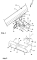
- the drawing shows trailer couplings 10 and 110, some of which have the same or similar components, which are accordingly provided with the same reference numbers or with reference numbers that are 100 larger for the trailer coupling 110 than for the trailer coupling 10.
- the trailer couplings 10, 110 have brackets 11, 111 which can be attached to a towing vehicle 90, for example a passenger car.
- the holder 11 comprises a base holder 12 arranged on a cross member 91 of the towing vehicle 90, from which 2 holding legs 13 protrude.
- a dome carrier 14 is arranged between the holding legs 13.
- the dome carrier 14 is screwed to the holding legs 13 by means of screws 15, which penetrate holes 16 of the dome carrier 14 on a vehicle-side holding section 20.
- the dome carrier 14 is therefore firmly attached to the holder 11.
- a socket holder 17 protrudes laterally from the holder 11, to which a trailer socket (not shown) can be attached.
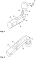
- a holder 111 is provided which can be attached to the towing vehicle 90, for example attachable to a cross member (not shown), and which mounts the dome carrier 114 in a movable manner.
- the dome carrier 114 is pivotally and/or displaceably mounted on the holder 111.
- a bearing head 118 of the holder 111 engages in a bearing receptacle 119 on a holding section 20 of the dome carrier 114 at the vehicle-side end region of the dome carrier 114, so that storage is provided in the manner of a ball joint.
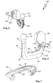
- the dome carrier 114 is, for example, between one in Figure 5 shown position of use, which is intended for towing a trailer 92, and a non-use position adjustable behind a bumper, not shown, for example closer to the cross member.
- a lock (not shown) is present to lock the dome carrier 114 at least in the position of use.
- the dome supports 14, 114 each have a coupling ball 22 at their end regions 21 remote from the towing vehicle 90, which serves as a coupling element 23 for coupling the trailer 92 (shown schematically).
- the coupling balls 22 are provided on arm sections 24 which are high in the position of use of the trailer couplings 10, 110.
- the arm sections 24 extend with a curvature 25 into an arm section 26 which runs essentially horizontally when the dome supports 14, 114 are in use.
- the arm section 26 and the end region 21 are virtually in one piece, i.e. the end region 21 is provided at a free end of the arm section 26.
- the section of the dome carrier 14 that projects freely in front of the holder 11 is referred to as the arm section 26.
- the trailer couplings 10, 110 are designed to have both a force acting on the coupling element 23 in a vertical direction or z-direction, hereinafter referred to as support load Fz, as well as a force acting on the coupling element 23 in a horizontal direction or x-direction load, hereinafter referred to as tensile load Fx.
- a single force sensor 30 is sufficient for this.
- the force sensor 30 can, for example, be a strain gauge 31 or another deformation sensor 35, for example a pressure sensor, which is clamped between two actuation resistances on the dome carrier 14.
- the force sensor 30 is optimally placed at an attachment location 32 so that its force signal 33 represents both the tensile load Fx and the supporting load Fz.
- the dome support 14 is shown when loaded with a tensile load Fx, for example a force of 5 kN.
- a tensile load Fx for example a force of 5 kN.
- Fz still acting support load
- a deformation region 42 is formed, in particular on the inside of the curvature 25.
- the deformation area 42 extends into the deformation area 40 ( Figure 2 ).
- the force sensor 30 is expediently arranged in the overlap area 43 so that it can be actuated by loading the coupling element 23 with the tensile load Fx as well as with the support load Fz and its force signal 33 represents both forces.
- the trailer coupling 110 also makes do with a single force sensor 30.
- a deformation region 44 is formed on the inside of the curvature 27.
- a deformation also takes place on the underside 29 when the coupling element 23 is loaded, which is located in a deformation area 45.
- the arrangement of a force sensor on the underside of a dome support i.e. closer to a road, is rather unfavorable. Therefore, the force sensor 30 is arranged at the attachment location 132 in the curvature 27. There, the force sensor 30 is also protected from environmental influences by the bumper, not shown, of the towing vehicle 90.
- An evaluation device 150 is located near the force sensor 30, for example directly next to the force sensor 30, so that a short line connection 51 is also provided here.
- a further force sensor 34 in particular a strain gauge, could be provided on the underside 29 of the dome carrier 14 in the deformation region 41.
- the evaluation devices 50, 150 can, for example, display the support load Fz and the train load Fx, temporarily store them, transmit them to an on-board network 93 of the towing vehicle 90 or the like.
- the evaluation devices 50, 150 can also determine a mass m of the trailer 92 from the force signal 33, for which the method explained at the beginning is preferred.
- evaluation devices 50, 51 work as follows, where in Figure 9 The block diagram shown is an example of both evaluation devices 50, 150.
- the evaluation device 50 includes, for example, a processor 52 and a memory 53 in which an evaluation module 54 is stored.
- Figure 10 shows a simplified program flow of the evaluation module 54, the commands of which can be executed by the processor 52 in order to determine the support load Fz and in particular the mass m of the trailer 92 based on the force signal 33.
- the evaluation module 54 initializes the force sensor 30 and an acceleration sensor 55.
- the acceleration sensor 55 is on board the evaluation device 50.
- the initialization in step S1 preferably provides that the evaluation device 50 or 150 or the evaluation module 54 also carries out a temperature measurement, since the temperature in the rear area of the towing vehicle 90 fluctuates greatly, for example due to exhaust gases.
- a temperature sensor 58 can be provided on board the evaluation device 50 or 150.
- a preferred embodiment provides that the evaluation device 50 or 150 first determines an initial value of the force sensor 36 when the trailer coupling 10 or 110 is still unloaded, so to speak a base value at a given temperature. Based on this base value, the force signal 33 then changes when the trailer coupling 10 or 110 is loaded when the trailer is attached, i.e. exerts a force on the coupling carrier 14 or 114.
- the evaluation module 54 recognizes that the towing vehicle 90 is stationary.
- the acceleration sensor 55 does not detect any acceleration a.
- the acceleration sensor 55 is preferably designed to detect not only the acceleration acting in the X direction a, which could actually be called acceleration ax, but also to determine the accelerations ay and az acting in the Y direction and in the Z direction. Based on the acceleration values ax, ay and az, the acceleration sensor 55 and/or the evaluation device 50, 150 is able to determine an angle of inclination ⁇ at which the towing vehicle 90 stands with respect to the X direction relative to a surface U, for example downhill or uphill. If the towing vehicle 90 is standing on a horizontal, flat surface, only one force in the Z direction acts on the dome support 14, 114, namely the gravitational acceleration g. The determination of the angle of inclination ⁇ is expediently carried out when the towing vehicle 90 is stationary.
- an inclination sensor 59 can also be provided on board the evaluation device 50, 150.
- the evaluation module 54 detects an acceleration a of the towing vehicle 90, which begins at time t1. The evaluation module 54 then ends the determination of the support load Fz.
- the acceleration at time t1 is still relatively low. However, if the acceleration a reaches a value a1 at a time t2, the evaluation module 54 detects a significant acceleration that is suitable for determining the mass m of the trailer 92.
- an algorithm for trailer mass detection then runs in a step S4, in the context of which the evaluation device 50, expediently taking into account the previously determined support load Fz and temporarily stored in the memory 53, the mass m of the Trailer 92.
- the mass m is also expediently stored in memory 53.
- the evaluation module 54 takes into account the value for the angle of inclination, for example according to formula (9) and/or the initially determined temperature base value of the force signal (33) in step S3.
- step S4 ends at a time t3, namely when the acceleration of the towing vehicle 90 ends when an acceleration value a2 is reached and/or the towing vehicle 90 exceeds a limit speed at which, for example, rolling resistance influences and/or air resistance influences increase so significantly that a reliable Mass recognition is no longer easily possible.
- the flowchart also includes according to Figure 10 another state w, namely wait, into which the evaluation module 54 goes until the towing vehicle 90 has come to a standstill again.
- the evaluation device 50 shows, for example, the support load and/or the mass m of the trailer 92 on a display 56.
- the evaluation device 50 it is also possible for the evaluation device 50 to be connected to the on-board electrical system 93 of the towing vehicle 90 via a bus interface 57, for example in order to receive acceleration values and/or values determined by it for the support load and/or the mass of the trailer and/or to transmit the train load to the vehicle electrical system 93, so that, for example, an electronic stabilization program can regulate the driving stability of the towing vehicle 90 based on the values thus obtained and/or the values can be displayed on a display, for example in the dashboard area of the towing vehicle 90.
- additional force sensors can of course be provided on the holders 11, 111 and/or the dome supports 14, 114.
- force sensors provided essentially for a dedicated support load detection or a dedicated tensile force detection can also be advantageous, e.g. a force sensor 36 on the deformation area 42 which deforms when the dome carrier 14 is subjected to tensile force.
- the deformation area 42 deforms only insignificantly when the support load is applied, so that its force signal essentially represents the tensile load and can be evaluated accordingly by the evaluation device 50, 150.
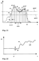
- the evaluation device 50 or 150 each forms intermediate mean values a0 to a10 of the acceleration value ax relevant in the X direction. This means that not every small change in the acceleration value ax is considered, but rather an intermediate mean value formed over a short period of time ⁇ t of, for example, 0.1 s or 0.2 s. On the other hand, the average is not formed over a very long period of time, for example between times t4 and t6. It is therefore a type of block formation or sampling process.
- the evaluation device 50, 150 begins, for example, with determining the trailer mass m at a time t4, at which the intermediate mean value a0 of the acceleration value ax relevant in the X direction has exceeded a minimum acceleration value amin1.
- the intermediate mean value a0 is already above the minimum acceleration value amin1, but still below a further minimum acceleration value amin2.
- the evaluation or determination of the trailer mass value m does not yet begin, but the evaluation device 50, 150 is ready to do so.
- the intermediate mean values a1 to a9 are above the upper minimum acceleration value amin2, but from time t6 they are again below this threshold.
- the intermediate mean value a10 is still above the lower minimum threshold amin1, but no longer above the upper minimum threshold amin2.
- the evaluation device 50 or 150 selects several successive intermediate mean values from the intermediate mean values a1-a9, but only if at least 3 or 4 consecutive intermediate mean values a1-a9 had exceeded the upper minimum threshold amin2. This is basically another way of saying that the duration of a journey of the towing vehicle 90 to be evaluated should have a minimum duration of, for example, tmin.
- tmin is shown as an example over 4 of the blocks or intermediate mean values a1-a9.
- the minimum duration tmin can also be chosen differently, for example smaller or larger, so that it extends completely between the times t5 and t6, for example.
- FIG 12 A course of the acceleration value ax is shown, which the acceleration sensor 55 detects in the X direction. However, the towing vehicle 90 is at an angle, for example uphill.
- the evaluation device 50 or 150 corrects the acceleration value ax and generates an acceleration value axk related to the towing vehicle 90, in which the influence of the inclination angle ⁇ in the X direction is corrected.
- the acceleration sensor 55 is expediently designed to determine the gravitational acceleration g acting in the X, Y and Z directions and the evaluation device 50 determines the inclination angle ⁇ from this.
- the evaluation device 50, 150 expediently uses the corrected acceleration value axk as a basis (see, for example, formula (9)).
Description
Die Erfindung betrifft eine Anhängekupplung für ein Zugfahrzeug, gemäß dem Oberbegriff des Anspruch 1.The invention relates to a trailer coupling for a towing vehicle, according to the preamble of
Eine derartige Anhängekupplung ist beispielsweise in
Aus
Bei dieser Anhängekupplung sind also die Stützlast und eine Zuglast, die beim Zugbetrieb des Gespanns auftritt, erfassbar. Für einen sicheren Fahrbetrieb ist es vorteilhaft, wenn eine Stützlast richtig erfassbar und einstellbar ist. Ferner darf auch die Masse oder das Gesamtgewicht des Anhängers nicht überschritten werden.With this trailer coupling, the support load and a tensile load that occurs when the trailer is towing can be recorded. For safe driving, it is advantageous if a support load can be correctly detected and adjusted. Furthermore, the mass or total weight of the trailer must not be exceeded.
Es ist daher die Aufgabe der vorliegenden Erfindung, Vorrichtungen und Verfahren anzugeben, um einen Anhänger-Massewert des Anhängers zu ermitteln.It is therefore the object of the present invention to provide devices and methods for determining a trailer mass value of the trailer.
Zur Lösung dieser Aufgabe ist eine Anhängekupplung gemäß der technischen Lehre des Anspruchs 1 vorgesehen. Zur Lösung der Aufgabe ist ferner ein Verfahren gemäß der technischen Lehre des Anspruchs 13 vorgesehen.To solve this problem, a trailer coupling according to the technical teaching of
Ein Grundgedanke der Erfindung ist es, dass ein Kraftsensor, beispielsweise ein dediziert zur Ermittlung einer durch Zugkraft bedingten Verformung der Anhängekupplung, insbesondere des Kuppelträgers oder der Halterung, vorgesehener Kraftsensor, anhand der zusätzlichen Auswertung des Beschleunigungswerts in der Lage ist, die Anhänger-Masse des Anhängers zu ermitteln. Dabei ist die Überlegung zu Grunde gelegt, dass sich eine Kraft als das Produkt aus Masse und Beschleunigung ermitteln lässt. Selbstverständlich ist es zweckmäßig, wenn die Auswerteeinrichtung zur Berücksichtigung weiterer Faktoren ausgestaltet ist, beispielsweise zur Auswertung und Berücksichtigung von Reibungswerten, Trägheitsmassen und dergleichen mehr. Das erfindungsgemäße Grundkonzept beruht jedoch auf der Ableitung der Masse des Anhängers aus dem Zugkraftsignal.A basic idea of the invention is that a force sensor, for example a force sensor dedicated to determining a deformation of the trailer coupling caused by tensile force, in particular of the dome carrier or the holder, is able to determine the trailer mass of the trailer based on the additional evaluation of the acceleration value to determine the trailer. This is based on the idea that a force can be determined as the product of mass and acceleration. Of course, it is expedient if the evaluation device is designed to take other factors into account, for example to evaluate and take into account friction values, inertial masses and the like. However, the basic concept according to the invention is based on deriving the mass of the trailer from the tractive force signal.
Der Beschleunigungswert ist dabei ein Beschleunigungswert in Fahrtrichtung oder x-Richtung, nicht jedoch ein beispielsweise um die Hochachse orientierter Gierraten-Beschleunigungswert.The acceleration value is an acceleration value in the direction of travel or x-direction, but not a yaw rate acceleration value oriented, for example, around the vertical axis.
Zweckmäßigerweise hat die Auswerteeinrichtung einen Signaleingang für ein Beschleunigungssignal. Beispielsweise ist eine Anschlussklemme, eine Buchse oder dergleichen für den Beschleunigungssensor vorhanden. Der Beschleunigungssensor ist bei dieser Ausgestaltung eine separate mit der Auswerteeinrichtung verbindbare Baueinheit.The evaluation device expediently has a signal input for an acceleration signal. For example, there is a connection terminal, a socket or the like for the acceleration sensor. In this embodiment, the acceleration sensor is a separate structural unit that can be connected to the evaluation device.
Es ist auch möglich, dass die Auswerteeinrichtung einen Beschleunigungssensor an Bord hat.It is also possible for the evaluation device to have an acceleration sensor on board.
Weiterhin ist es vorteilhaft, wenn die Auswerteeinrichtung einen Temperatursensor aufweist, so dass sie eine Temperaturkompensation vornehmen kann.Furthermore, it is advantageous if the evaluation device has a temperature sensor so that it can carry out temperature compensation.
Dabei liegt die Erkenntnis zu Grunde, dass der Kupplungsarm oder die sonstige Stelle, an der der mindestens eine Kraftsensor angeordnet ist, beispielsweise im Einwirkungsbereich von Abgasen liegt und dadurch erwärmt wird. Eine Temperaturkompensation oder Berücksichtigung eines Temperatureinflusses bei der Ermittlung von werten oder Daten ist daher vorteilhaft. An dieser Stelle sei bemerkt, dass die Temperaturkompensation selbstverständlich auch bei einer reinen Stützlastmessung zweckmäßig ist, also einen an sich eigenständigen erfindungsgemäßen Gedanken bei einer Kraftmessung an einer Anhängekupplung darstellt.This is based on the knowledge that the coupling arm or the other location at which the at least one force sensor is arranged is, for example, in the area of influence of exhaust gases and is thereby heated. Temperature compensation or consideration of a temperature influence when determining values or data is therefore advantageous. At this point it should be noted that temperature compensation is of course also useful for a pure support load measurement, and therefore represents an independent idea according to the invention for a force measurement on a trailer coupling.
Es ist jedoch nicht unbedingt notwendig, dass ein Temperatursensor vorgesehen ist. Auch der mindestens eine Kraftsensor kann bereits dazu dienen, eine Temperaturkompensation oder eine Berücksichtigung einer Temperatur zu ermöglichen:
Die Temperaturkompensation kann z.B. bereits am Anfang einer Messung stehen, d.h. dass beispielsweise erfindungsgemäß das von einem jeweiligen Kraftsensor erzeugte Kraftsignal noch ohne Stützlast oder Zuglast als Basiswert dient, vergleichbar beispielsweise mit der Einstellung einer Tara bei einer Waage. Somit wird also beispielsweise der mindestens eine Kraftsensor sozusagen kalibriert. Bei einer unbelasteten Anhängekupplung liefert der Kraftsensor, der beispielsweise in der Art einer Widerstands-Messbrücke ausgestaltet ist, beispielsweise einen ersten Kraftsignalwert bei einer ersten Temperatur und einen zweiten Kraftsignalwert bei einer zweiten, von der ersten Temperatur verschiedenen Temperatur. Bei einer späteren Auswertung einer einen dem Kuppelträger angreifenden Last, also einer Bestimmung einer Größe des Anhängers, z.B. Stützlast oder Masse des Anhängers, wird der jeweilige Kraftsignalwert als Basiswert angesetzt, eignet sich also beispielsweise als Korrekturwert.However, it is not absolutely necessary that a temperature sensor is provided. The at least one force sensor can also serve to enable temperature compensation or to take a temperature into account:
The temperature compensation can, for example, already be at the beginning of a measurement, that is, for example, according to the invention, the force signal generated by a respective force sensor still serves as a base value without a supporting load or tensile load, comparable, for example, to setting a tare on a scale. Thus, for example, the at least one force sensor is calibrated, so to speak. In the case of an unloaded trailer coupling, the force sensor, which is designed, for example, in the manner of a resistance measuring bridge, delivers, for example, a first force signal value at a first temperature and a second force signal value at a second temperature that is different from the first temperature. During a later evaluation of a load acting on the dome carrier, i.e. a determination of a size of the trailer, for example support load or mass of the trailer, the respective force signal value is set as the base value and is therefore suitable, for example, as a correction value.
Schließlich ist es auch vorteilhaft, wenn bei der Anhängekupplung oder deren Auswerteeinrichtung noch ein Neigungssensor zur Ermittlung eines Neigungswinkels und/oder eine Schnittstelle zum Empfang eines Neigungswinkel-Werts, beispielsweise von einem an Bord des Zugfahrzeugs vorhandenen Neigungswinkelsensors, vorhanden ist. Der Neigungswinkel entspricht einer Schrägneigung des Kraftfahrzeugs bzw. Gespanns bestehend aus Kraftfahrzeug und Anhänger, z.B. wenn das Gespann hangabwärts oder hangaufwärts steht. Die erfindungsgemäße Auswerteeinrichtung bzw. das Verfahren sind zweckmäßigerweise dazu ausgestaltet, den Anhänger-Massewert in Abhängigkeit von dem Neigungswinkel-Wert zu ermitteln und/oder den Einfluss des Neigungswinkels zu eliminieren.Finally, it is also advantageous if the trailer coupling or its evaluation device also has an inclination sensor for determining an inclination angle and/or an interface for receiving an inclination angle value, for example from an inclination angle sensor present on board the towing vehicle. The angle of inclination corresponds to an inclined inclination of the motor vehicle or trailer consisting of motor vehicle and trailer, e.g. if the trailer is positioned downhill or uphill. The evaluation device or the method according to the invention are expediently designed to determine the trailer mass value as a function of the angle of inclination value and/or to eliminate the influence of the angle of inclination.
Der Neigungssensor kann aber auch durch den Beschleunigungssensor gebildet sein. Beispielsweise kann der Beschleunigungssensor die in drei zueinander winkeligen Achsrichtungen (X-Achse, Y-Achse und Z-Achse) jeweils eine Beschleunigung erfassen. Wenn das Kraftfahrzeug horizontal steht, misst der Beschleunigungssensor bei stehendem Kraftfahrzeug nur die in Z-Richtung wirkende Kraft, nämlich die Erdanziehungskraft bzw. g. Bei schrägstehendem Kraftfahrzeug hingegen misst der Beschleunigungssensor auch in Richtung der X-Achse und/oder der Y-Achse jeweils einen Anteil der Erdanziehungskraft bzw. Erdbeschleunigung g, so dass durch einen geeigneten, beispielsweise bei der Auswerteeinrichtung hinterlegten Algorithmus die Schrägneigung des Gespanns bzw. des Beschleunigungssensors erfassbar ist.The inclination sensor can also be formed by the acceleration sensor. For example, can the acceleration sensor, which detects acceleration in three mutually angled axis directions (X-axis, Y-axis and Z-axis). If the motor vehicle is horizontal, the acceleration sensor only measures the force acting in the Z direction, namely the force of gravity or g, when the motor vehicle is stationary. When the motor vehicle is at an angle, however, the acceleration sensor also measures a portion of the gravitational force or gravitational acceleration g in the direction of the Acceleration sensor can be detected.
An dieser Stelle sei bemerkt, dass die Neigungswinkelkompensation und/oder das Vorsehen eines Neigungssensors, insbesondere eines die Funktion eines Neigungssensors leistenden Beschleunigungssensors, und/oder einer Schnittstelle für ein Neigungswinkelsignal selbstverständlich auch bei einer reinen Stützlastmessung zweckmäßig ist, also einen an sich eigenständigen erfindungsgemäßen Gedanken bei einer Kraftmessung an einer Anhängekupplung darstellt.At this point it should be noted that the inclination angle compensation and/or the provision of an inclination sensor, in particular an acceleration sensor that performs the function of an inclination sensor, and/or an interface for an inclination angle signal is of course also useful for a pure support load measurement, i.e. an independent idea according to the invention during a force measurement on a trailer coupling.
Die Auswerteeinrichtung hat zweckmäßigerweise eine Bus-schnittstelle für einen Daten-Bus des Zugfahrzeugs. Beispielsweise umfasst die Schnittstelle eine CAN-Schnittstelle, eine LIN-Schnittstelle oder dergleichen. Über die Busschnittstelle kann beispielsweise der Beschleunigungswert empfangen werden. Zum Beispiel hat das Zugfahrzeug einen oder mehrere Beschleunigungssensoren. Es ist auch möglich, dass das Bordnetz des zugfahrzeugs Beschleunigungswerte übermittelt, die beispielsweise aufgrund von Drehzahlsignalen ermittelt wurden. Die Auswerteeinrichtung ist beispielsweise ausgestaltet, über die Bus-Schnittstelle den Massewert des Anhängers zu übertragen. Es versteht sich, dass anstelle einer Bus-Schnittstelle auch eine sonstige Datenschnittstelle möglich ist.The evaluation device expediently has a bus interface for a data bus of the towing vehicle. For example, the interface includes a CAN interface, a LIN interface or the like. For example, the acceleration value can be received via the bus interface. For example, the towing vehicle has one or more acceleration sensors. It is also possible for the towing vehicle's electrical system to transmit acceleration values that were determined, for example, based on speed signals. The evaluation device is designed, for example, to transmit the mass value of the trailer via the bus interface. It goes without saying that instead of a bus interface, another data interface is also possible.
Die Auswerteeinrichtung ist zweckmäßigerweise auch zur Ermittlung einer Stützlast, die auf der Anhängekupplung aufgrund des Anhängers lastet, ausgestaltet. In diesem Zusammenhang ist es vorteilhaft, wenn die Auswerteeinrichtung bei der Ermittlung des Anhänger-Massewerts des Anhängers eine Stützlast, die der Anhänger auf die Anhängekupplung ausübt, berücksichtigt. Eine Variante kann dabei zwar vorsehen, dass die Stützlast extern ermittelt und über einen entsprechenden Daten- oder Signaleingang an die Auswerteeinrichtung übermittelt wird. Bevorzugt ist es jedoch, wenn die Auswerteeinrichtung selbst dazu ausgestaltet ist, die stützlast zu ermitteln.The evaluation device is expediently also designed to determine a support load that is placed on the trailer coupling due to the trailer. In this context, it is advantageous if the evaluation device takes into account a support load that the trailer exerts on the trailer coupling when determining the trailer mass value of the trailer. A variant can provide that the support load is determined externally and transmitted to the evaluation device via a corresponding data or signal input. However, it is preferred if the evaluation device itself is designed to determine the supporting load.
Eine vorteilhafte Überlegung sieht vor, dass die Auswerteeinrichtung den Anhänger-Massewert nicht im Stand, sondern bei Fahrt des Zugfahrzeugs ermittelt. Beispielsweise ist es vorteilhaft, wenn die Auswerteeinrichtung den Anhänger-Massewert in Abhängigkeit von einer Fahrgeschwindigkeit des Zugfahrzeugs ermittelt. So sieht eine Variante vor, dass die Auswerteeinrichtung erst bei Überschreiten eines unteren Geschwindigkeitsgrenzwertes mit der Ermittlung des Anhänge-Massewerts beginnt. Es ist zweckmäßig, wenn die Auswerteeinrichtung den Anhänger-Massewert nur bis zum Erreichen eines oberen Geschwindigkeitsgrenzwertes ermittelt. Hierbei liegt die Überlegung zu Grunde, dass bei geringen Fahrgeschwindigkeiten im Wesentlichen die Zugkraft eine der Anhängekupplung wirkt, während bei größeren Geschwindigkeiten beispielsweise auch Luftwiderstand-Einflüsse zu berücksichtigen wären. Selbstverständlich ist es denkbar, einen Algorithmus bei einer erfindungsgemäßen Anhängekupplung vorzusehen bzw. bei deren Auswerteeinrichtung, der auch Luftwiderstandseinflüsse berücksichtigt und gegebenenfalls eliminiert.An advantageous consideration provides that the evaluation device determines the trailer mass value not when the towing vehicle is stationary, but rather when it is moving. For example, it is advantageous if the evaluation device determines the trailer mass value as a function of a driving speed of the towing vehicle. One variant provides that the evaluation device only begins to determine the trailer mass value when a lower speed limit value is exceeded. It is useful if the evaluation device only determines the trailer mass value until an upper speed limit is reached. This is based on the idea that at low driving speeds, the tractive force of one of the trailer couplings essentially acts, while at higher speeds, for example, air resistance influences would also have to be taken into account. Of course, it is conceivable to provide an algorithm in a trailer coupling according to the invention or in its evaluation device, which also takes air resistance influences into account and, if necessary, eliminates them.
Es ist auch vorteilhaft, wenn die Auswerteeinrichtung das Kraftsignal erst bei Überschreiten eines unteren Mindest-Beschleunigungswerts zur Ermittlung der Anhänger-Masse auswertet. Die Auswertung eines Beschleunigungswerts nur bei überschreiten eines unteren Mindest-Beschleunigungswerts hat zum Beispiel den Vorteil, dass Störeinflüsse, beispielsweise aufgrund von Vibrationen etc., die Auswertung nicht oder nur unwesentlich stören. Beispielsweise müssen derartige Störeinflüsse dann nicht eliminiert werden.It is also advantageous if the evaluation device only evaluates the force signal to determine the trailer mass when a lower minimum acceleration value is exceeded. Evaluating an acceleration value only when a lower minimum acceleration value is exceeded has the advantage, for example, that interference, for example due to vibrations etc., does not interfere with the evaluation or only insignificantly. For example, such disruptive influences do not then have to be eliminated.
Ferner kann auch eine obere Grenze vorgesehen sein, das heißt dass die Auswerteeinrichtung das Kraftsignal nur bis zum Erreichen eines Maximal-Beschleunigungswerts auswertet.Furthermore, an upper limit can also be provided, which means that the evaluation device only evaluates the force signal until a maximum acceleration value is reached.
Eine weitere Variante der Erfindung sieht vorteilhaft vor, dass die Auswerteeinrichtung das Kraftsignal während einer Zeitdauer kontinuierlich ansteigende Beschleunigungswerte oder kontinuierlich abfallende Beschleunigungswerte als ein die an der Anhängekupplung angreifende Zugkraft und/oder Schubkraft repräsentierendes Signal auswertet. Wenn also beispielsweise die Beschleunigungskurve ansteigt (bei einem Beschleunigungsvorgang) oder abfällt (bei einem Bremsvorgang) wertet die Auswerteeinrichtung das Kraftsignal als Zugkraft-Signal aus und/oder ermittelt die Auswerteeinrichtung aus dem Kraftsignal jeweils den Anhänger-Massewert.A further variant of the invention advantageously provides that the evaluation device evaluates the force signal during a period of continuously increasing acceleration values or continuously decreasing acceleration values as a signal representing the tensile force and/or thrust force acting on the trailer coupling. For example, if the acceleration curve increases (during an acceleration process) or decreases (during a braking process), the evaluation device evaluates the force signal as a tractive force signal and/or the evaluation device determines the trailer mass value from the force signal.
Eine Variante der Erfindung sieht vor, dass die Auswerteeinrichtung erkennt, wenn das Zugfahrzeug aus dem Stand beschleunigt. Bevorzugt wird dann die Messung der Stützlast bzw. deren Ermittlung gestoppt. Stattdessen beginnt die Auswerteeinrichtung mit der Auswertung der Zugkraft und der Beschleunigungswerte und stoppt diesen Vorgang erst dann, wenn die Beschleunigung endet oder wenn die Fahrgeschwindigkeit einen bestimmten Grenzwert überschreitet, beispielsweise 5 bis 10 km/h.A variant of the invention provides that the evaluation device detects when the towing vehicle accelerates from a standstill. The measurement of the support load or its determination is then preferably stopped. Instead, the evaluation device begins with the evaluation of the tractive force and the acceleration values and only stops this process when the acceleration ends or when the driving speed exceeds a certain limit, for example 5 to 10 km/h.
Eine bevorzugte Ausführungsform sieht vor, dass das Kraftsignal des mindestens einen Kraftsensors beides repräsentiert, nämlich eine an der Anhängekupplung angreifende Stützlast und eine an der Anhängekupplung angreifende Zuglast des Anhängers. Die Auswerteeinrichtung ist zweckmäßigerweise zur Auswertung des Kraftsignals zur Ermittlung der Stützlast und zur Ermittlung der Zuglast in Abhängigkeit von einem Fahrzustand des Zugfahrzeugs ausgestaltet.A preferred embodiment provides that the force signal of the at least one force sensor represents both, namely a support load acting on the trailer coupling and a tensile load of the trailer acting on the trailer coupling. The evaluation device is expediently designed to evaluate the force signal to determine the support load and to determine the train load depending on a driving condition of the towing vehicle.
Vorteilhaft umfasst der mindestens eine Kraftsensor einen auf Druck- und/oder Zug empfindlichen Verformungssensor, der an einem an dem Kuppelträger oder der Halterung vorgesehenen Anbringungsort angeordnet ist, an dem eine Dehnungsverformung und/oder Stauchungsverformung aufgrund einer auf die Anhängekupplung einwirkenden, durch den Anhänger verursachten Kraft messbar ist, wobei der Anbringungsort so gewählt ist, dass an dem Anbringungsort eine durch eine bei einem Zugbetrieb des Anhängers auf das Kuppelelement wirkende Zuglast verursachbare Verformung zur Betätigung des mindestens einen Kraftsensors vorhanden ist und eine durch eine auf die Anhängekupplung wirkende Stützlast des Anhängers verursachbare Verformung zur Betätigung des mindestens einen Kraftsensors vorhanden ist.Advantageously, the at least one force sensor comprises a deformation sensor sensitive to pressure and/or tension, which is arranged at an attachment location provided on the dome carrier or the holder, at which an expansion deformation and/or compression deformation due to an acting on the trailer coupling caused by the trailer Force can be measured, the attachment location being chosen such that at the attachment location there is a deformation caused by a tensile load acting on the coupling element during towing operation of the trailer for actuating the at least one force sensor and a deformation caused by a support load of the trailer acting on the trailer coupling Deformation for actuation of the at least one force sensor is present.
Das Wort "Zuglast" soll so verstanden werden, dass sowohl eine Belastung auf Zug, d.h. beim Ziehen des Anhängers, als auch eine Belastung auf Druck, d.h. beim Schieben des Anhängers bzw. Auflaufen auf das zugfahrzeug bei beispielsweise einem Bremsen unter den Begriff Zuglast fällt. Mithin kann also eine Belastung der Anhängekupplung in Horizontalrichtung bei Geradeausfahrt des Gespanns als Zuglast verstanden werden.The word "tensile load" should be understood to mean that both a tensile load, i.e. when pulling the trailer, and a compressive load, i.e. when the trailer is pushed or collided with the towing vehicle when braking, for example, fall under the term tensile load . Therefore, a load on the trailer coupling in the horizontal direction when the trailer is driving straight ahead can be understood as a tensile load.
Selbstverständlich tritt auch in vertikaler Richtung nicht nur eine Drucklast auf, die als Stützlast bezeichnet wird, sondern auch eine Belastung nach vertikal oben, zum Beispiel beim Überfahren einer Kuppe oder Bodenunebenheit. Zweckmäßigerweise ist der Anbringungsort für den mindestens einen Kraftsensor im Bereich einer größten durch die Zuglast verursachbaren Verformung des Kuppelträgers oder der Halterung vorgesehen.Of course, not only does a compressive load occur in the vertical direction, which is referred to as the support load, but also a vertical load, for example when driving over a hill or uneven ground. The attachment location for the at least one force sensor is expediently provided in the area of the greatest deformation of the dome carrier or the holder that can be caused by the tensile load.
Der Kuppelträger ist erfindungsgemäß als ein Kupplungsarm ausgestaltet. Der Kupplungsarm enthält erfindungsgemäß mehrere Krümmungen, Winkel und dergleichen. Das Kuppelelement ist beispielsweise eine Kupplungskugel, wobei selbstverständlich auch andere Geometrien, beispielsweise polygonale, Drehkräfte übertragende Kuppelelemente möglich sind. Bevorzugt ist das Kuppelelement fest am Kuppelträger angeordnet, insbesondere mit diesem einstückig. Es ist aber auch eine mehrteilige Bauweise möglich.According to the invention, the dome carrier is designed as a coupling arm. According to the invention, the coupling arm contains several curvatures, angles and the like. The coupling element is, for example, a coupling ball, although other geometries, for example polygonal coupling elements that transmit rotational forces, are of course also possible. The dome element is preferably arranged firmly on the dome carrier, in particular in one piece with it. However, a multi-part construction is also possible.
Die Halterung kann eine Halterung sein, an der der Kuppelträger fest montiert ist. Weiterhin sind auch Stecksysteme oder sonstige Systeme möglich, bei denen der Kuppelträger lösbar an der Halterung befestigbar ist, insbesondere mittels einer Steckverbindung. Es ist aber auch eine bewegliche Lagerung möglich, bei der der Kuppelträger beispielsweise schwenkbar und/oder schiebebeweglich an der Halterung gelagert ist.The holder can be a holder on which the dome carrier is firmly mounted. Furthermore, plug-in systems or other systems are also possible in which the dome carrier can be detachably attached to the holder, in particular by means of a plug-in connection. However, movable mounting is also possible, in which the dome carrier is mounted on the holder in a pivotable and/or sliding manner, for example.
Weiterhin ist es vorteilhaft, wenn der Anbringungsort im Bereich einer größten durch die Stützlast verursachbaren Verformung des Kuppelträgers oder der Halterung vorgesehen ist. Natürlich ist es zweckmäßig, wenn ein Anbringungsort gefunden werden kann, bei dem die Dehnungsverformung und Stauchungsverformung sowohl bei der Zuglast als auch bei der Stützlast jeweils maximal sind. Es gibt jedoch auch Situationen bzw. Geometrien von Halterung und/oder Kuppelträger, bei denen ein solcher optimaler Anbringungsort gar nicht erst gefunden werden kann. So kann beispielsweise die Verformung bei der Stützlast an einer anderen Stelle ihr Maximum haben als die Verformung bei der Zuglast. Zweckmäßig ist es dann, wenn sozusagen ein Kompromiss gefunden wird, so dass die durch die Zuglast verursachbare Verformung und die durch die Stützlast verursachbare Verformung einen ähnlichen Betrag oder den gleichen Betrag an dem als Kompromiss gefundenen Anbringungsort aufweisen.Furthermore, it is advantageous if the attachment location is provided in the area of the greatest deformation of the dome carrier or the holder caused by the support load. Of course, it is useful if an attachment location can be found at which the expansion deformation and compression deformation are maximum for both the tensile load and the supporting load. However, there are also situations or geometries of brackets and/or dome supports in which such an optimal attachment location cannot even be found. For example, the deformation in the supporting load can have its maximum at a different point than the deformation in the tensile load. It is useful if a compromise is found, so to speak, so that the deformation caused by the tensile load and the deformation caused by the support load have a similar amount or the same amount at the attachment location found as a compromise.
Ein weiterer Faktor bzw. einen Optimierungskriterium kann auch sein, dass der Anbringungsort möglichst an einer von einer Fahrbahn abgewandten Oberseite des Kuppelträgers oder der Halterung vorgesehen ist. Dadurch ist das Risiko, dass der Kraftsensor beschädigt wird, deutlich geringer.Another factor or optimization criterion can also be that the attachment location is provided, if possible, on an upper side of the dome carrier or the holder that is facing away from a roadway. This means that the risk of the force sensor being damaged is significantly lower.
Weiterhin ist es ein Optimierungskriterium, dass der Anbringungsort möglichst nahe bei einer Auswerte- und/oder Anzeigeeinrichtung angeordnet ist. Beispielsweise kann eine Leitungsverbindung zu einer Auswerte- und/oder Anzeigeeinrichtung möglichst kurz gewählt werden. Wenn also beispielsweise zwei Anbringungsorte alternativ zur Verfügung stehen, an denen jeweils eine zur Betätigung des Kraftsensors ausreichende Verformung bei Stützlast und Zuglast vorhanden ist, ein Anbringungsort jedoch näher bei der Auswerte- und/oder Anzeigeeinrichtung ist als der andere Anbringungsort, wird zweckmäßigerweise der näher gelegene Anbringungsort ausgewählt. Die Übertragungsverluste für die Signalübertragung vom Kraftsensor bzw. Verformungssensor zur auswertenden und/oder anzeigenden Einheit sind also kurz. Das Risiko der Einstrahlung von Fremdsignalen oder sonstigen Störungen wird dadurch wesentlich kleiner.Furthermore, it is an optimization criterion that the attachment location is arranged as close as possible to an evaluation and/or display device. For example, a line connection to an evaluation and/or display device can be chosen to be as short as possible. If, for example, two mounting locations are alternatively available, at each of which there is sufficient deformation in the support load and tensile load to actuate the force sensor, but one mounting location is closer to the evaluation and / or display device than the other mounting location, the closer location is expediently used Installation location selected. The transmission losses for signal transmission from the force sensor or deformation sensor to the evaluating and/or displaying unit are therefore short. This significantly reduces the risk of external signals or other interference.
Beispielsweise kann der Verformungssensor einen Dehnungsmessstreifen und/oder einen Drucksensor umfassen.For example, the deformation sensor can comprise a strain gauge and/or a pressure sensor.
Selbstverständlich kann es zweckmäßig sein, dass mehrere Kraftsensoren vorhanden sind, von denen mindestens einer ein Verformungssensor, der die Zuglast und die Stützlast messen kann. Wenn mehrere Kraftsensoren vorhanden sind, möglicherweise auch mehrere sozusagen multifunktionale Kraftsensoren, die jeweils Stützlast und Zuglast messen können, erhöht dies die Messgenauigkeit.Of course, it can be useful for several force sensors to be present, at least one of which is a deformation sensor that can measure the tensile load and the support load. If there are several force sensors, possibly several multifunctional force sensors, each of which can measure the support load and tensile load, this increases the measurement accuracy.
Beispielsweise kann die Dehnung bzw. Verformung des Kuppelträgers oder der Halterung anhand einer Finite-Elemente-Berechnung ermittelt werden.For example, the expansion or deformation of the dome support or the holder can be determined using a finite element calculation.
Der Kraftsensor bzw. Verformungssensor liefert also sowohl bei Belastung mit einer Zuglast als auch bei einer Belastung der Anhängekupplung mit einer Stützlast jeweils ein Kraftsignal. Bevorzugt ist bei dieser Ausführungsform vorgesehen, dass die Anhängekupplung eine Auswerteeinrichtung umfasst, die zur Auswertung des Kraftsignals in Abhängigkeit von einem Beschleunigungszustand und/oder einem Geschwindigkeitszustand des Zugfahrzeugs und somit auch der Anhängekupplung ausgestaltet ist. Wenn das Gespann steht, lastet im Wesentlichen die Stützlast auf der Anhängekupplung. Die Geschwindigkeit ist also beispielsweise gleich null. Auch die Beschleunigung bzw. der Beschleunigungswert ist null. Dann ermittelt die Auswerteeinrichtung vorteilhaft die Stützlast anhand des Kraftsignals. Wenn das Gespann jedoch fährt, insbesondere wenn es beschleunigt oder abbremst, greift eine Zuglast an der Anhängekupplung an. Dann ermittelt die Auswerteeinrichtung zweckmäßigerweise die Zuglast.The force sensor or deformation sensor therefore delivers a force signal both when the trailer coupling is loaded with a tensile load and when the trailer coupling is loaded with a support load. In this embodiment, it is preferably provided that the trailer coupling comprises an evaluation device which is designed to evaluate the force signal as a function of an acceleration state and/or a speed state of the towing vehicle and thus also of the trailer coupling. When the trailer is stationary, the supporting load is essentially applied the trailer coupling. So, for example, the speed is zero. The acceleration or acceleration value is also zero. The evaluation device then advantageously determines the support load based on the force signal. However, when the trailer is moving, especially when it is accelerating or braking, a tensile load acts on the trailer coupling. The evaluation device then expediently determines the tensile load.
Bevorzugt ist eine Auswerteeinrichtung vorgesehen, beispielsweise die vorgenannte Auswerteeinrichtung, die zur Ermittlung eines Anhänger-Massewerts des Anhängers anhand eines oder mehrerer Kraftsignale des mindestens einen Kraftsensors und eines Beschleunigungswerts ausgestaltet ist. Anhand der Werte für die Stützlast und für die Zuglast sowie des Beschleunigungswerts kann also die Auswerteeinrichtung gemäß dieser Ausführungsform der Erfindung eine Anhängermasse ermitteln.An evaluation device is preferably provided, for example the aforementioned evaluation device, which is designed to determine a trailer mass value of the trailer based on one or more force signals from the at least one force sensor and an acceleration value. Based on the values for the support load and for the train load as well as the acceleration value, the evaluation device according to this embodiment of the invention can determine a trailer mass.
Die nachfolgende Vorgehensweise ist dabei bevorzugt:
In vertikaler Richtung, d.h. in Z-Richtung wirkt die Stützlast Fz auf die Anhängekupplung: ![]()
In the vertical direction, ie in the Z direction, the vertical load Fz acts on the trailer coupling:![]()
In der Formel (1) sind g die Erdbeschleunigung und st die auf das Kuppelelement wirkende Stützmasse.In formula (1), g is the acceleration due to gravity and st is the supporting mass acting on the coupling element.
Eine in x-Richtung bzw. horizontal in Fahrzeuglängsrichtung an der Anhängekupplung angreifende Zuglast Fx kann mit der nachfolgenden Formel (2) zusammengefasst werden: ![]()
![]()
Die einzelnen Faktoren der Zuglast Fx sind dabei die Trägheitskraft FT, die Luftwiderstandskraft FL, eine die Rollreibung verursachte Kraft FR und eine Kraft Frot, in der die durch die Trägheit von Reifen und anderen rotatorischen Massen bedingten Kräfte zusammengefasst sind.The individual factors of the tensile load Fx are the inertia force FT, the air resistance force FL, a force FR caused by the rolling friction and a force Frot, which combines the forces caused by the inertia of tires and other rotating masses.
Bei geringen Geschwindigkeiten kann die Luftwiderstandskraft FL vernachlässigt werden. Es ist daher vorteilhaft, die erfindungsgemäße Ermittlung einer Anhängermasse bei relativ niedrigen Geschwindigkeiten durchzuführen, bei denen der Luftwiderstand noch gering ist. Selbstverständlich ist es auch denkbar, dass beispielsweise der Einfluss des Luftwiderstands von der Auswerteeinrichtung geschwindigkeitsabhängig ermittelt wird, um den jeweiligen Einfluss auf das Gesamt-Resultat der Zuglast Fx zu eliminieren.At low speeds, the air resistance force FL can be neglected. It is therefore advantageous to carry out the determination of a trailer mass according to the invention at relatively low speeds at which the air resistance is still low. Of course, it is also conceivable that, for example, the influence of air resistance is determined by the evaluation device depending on the speed in order to eliminate the respective influence on the overall result of the tensile load Fx.
Wenn jedoch die Luftwiderstandskraft eliminiert wird, kann die obige Formel (2) wie folgt vereinfacht werden: ![]()
![]()
Die durch die Rollreibung verursachte, an der Anhängekupplung angreifende Kraft FR wird durch die Masse m des Anhängers beeinflusst, wobei jedoch ein Teil dieser Masse von der Anhängekupplung abgestützt wird, d.h. so dass diese Stützlast oder Stützmasse keinen-Einfluss auf die Rollreibung hat. Die Stützmasse st ist also bei der folgenden Formel (4) von dem Massewert m subtrahiert: ![]()
![]()
In der Formel (4) sind g die Erdbeschleunigung und µ ein Rollwiderstandskoeffizient. Der Rollwiderstandkoeffizient kann als ein konstanter Wert, z.B. Mittelwert, angesehen werden, der bei einer üblichen Bereifung bzw. bei durchschnittlichen Fahrbahnbelägen vorhanden ist.In formula (4), g is the acceleration due to gravity and µ is a rolling resistance coefficient. The rolling resistance coefficient can be viewed as a constant value, e.g. average value, which is present with standard tires or average road surfaces.
Die Trägheitskraft FT wird im Wesentlichen durch die Anhängermasse m und die Beschleunigung ax in X-Richtung bestimmt: ![]()
![]()
Wenn die Formeln (4) und (5) in die Formel (3) eingesetzt werden, ergibt sich folgendes: ![]()
![]()
Wenn dann noch die Formel (1) berücksichtigt wird, kann man folgende Formel entwickeln: ![]()
![]()
Durch Umformung der Formel (7) kann die Masse m des Anhängers wie folgt bestimmt werden: ![]()
![]()
Unter Berücksichtigung der Überlegung, dass die Rotationsbeschleunigung nur geringe Kräfte verursacht, d.h. dass das Verhältnis der Kraft Frot zur Gesamt-Kraft Fx in Horizontalrichtung wie folgt lautet ![]()
![]()
Eine vorteilhafte Variante der Erfindung sieht dabei vor, dass mit einem einzigen Kraftsensor beide Kräfte Fx und Fz ermittelt werden. Dabei ist die Auswerteeinrichtung zweckmäßigerweise so ausgestaltet, dass sie zunächst im Stand die durch die Stützlast verursachten Kräfte, d.h. die Kräfte in z-Richtung, nämlich die Kraft Fz, ermittelt und bei der anschließenden Beschleunigung des Gespanns die in X-Richtung wirkende Kraft Fx. In diesem Zusammenhang ist es vorteilhaft, wenn die Auswerteeinrichtung einen Beschleunigungswert und/oder einen Geschwindigkeitswert auswertet, um sozusagen zwischen den einzelnen Kraftermittlungen umzuschalten.An advantageous variant of the invention provides that both forces Fx and Fz are determined with a single force sensor. The evaluation device is expediently designed in such a way that it initially determines the forces caused by the support load, i.e. the forces in the z direction, namely the force Fz, when the vehicle is stationary, and the force Fx acting in the X direction when the vehicle is subsequently accelerated. In this context, it is advantageous if the evaluation device evaluates an acceleration value and/or a speed value in order to switch, so to speak, between the individual force determinations.
So ist es beispielsweise vorteilhaft, dass zunächst die in vertikaler Richtung wirkende Kraft Fz ermittelt wird und die Auswerteeinrichtung den dabei ermittelten Wert in die obige Formel (8) sowie den anschließend bei der Beschleunigung des Gespanns ermittelten Wert der Kraft Fx zur Ermittlung der Masse des Anhängers anhand beispielsweise der Formel (8) auswertet.For example, it is advantageous that the force Fz acting in the vertical direction is first determined and the evaluation device enters the value determined in the above formula (8) as well as the value of the force Fx determined when the trailer is accelerated to determine the mass of the trailer evaluated using, for example, formula (8).
Eine bevorzugte Ausführungsform sieht vor, dass sozusagen der Beschleunigungssensor in Richtung der X-Achse kalibriert wird, d.h. dass bei einem Beschleunigungsvorgang aus dem Stand der von dem Beschleunigungssensor oder dem Bordnetz des Zugfahrzeugs gelieferte Beschleunigungswert um den durch die Schrägneigung des Kraftfahrzeugs bzw. Gespanns hervorgerufenen Anteil des Beschleunigungswerts korrigiert wird. Der Beschleunigungssensor wird sozusagen initialisiert.A preferred embodiment provides that the acceleration sensor is, so to speak, calibrated in the direction of the of the acceleration value is corrected. The acceleration sensor is, so to speak, initialized.
Eine Formel zur Korrektur des in Fahrzeuglängsrichtung wirkenden, um die Einwirkung der Schrägneigung des Gespanns korrigierten Beschleunigungswerts, d.h. des in X-Richtung wirkenden um den Hangabtrieb korrigierten Beschleunigungswerts axkorrigiert, lautet beispielsweise wie folgt: ![]()
![]()
Die Auswerteeinrichtung ist vorzugsweise dazu ausgestaltet, eine Mittelwertbildung durchzuführen. Beispielsweise bildet die Auswerteeinrichtung mehrere Zwischen-Mittelwerte des Beschleunigungswerts über aufeinanderfolgende zeitintervalle und wertet diese Mittelwerte aus.The evaluation device is preferably designed to carry out averaging. For example, the evaluation device forms several intermediate average values of the acceleration value over successive time intervals and evaluates these average values.
Beispielsweise führt die Auswerteeinrichtung eine Auswertung einer Beschleunigungsfahrt nur dann durch, wenn ein erster Zwischen-Mittelwert eine Beschleunigung von beispielsweise mehr als 1 m/s2 repräsentiert. Das ist dann ein Anfangskriterium.For example, the evaluation device only carries out an evaluation of an acceleration run if if a first intermediate mean value represents an acceleration of, for example, more than 1 m/s 2 . That is then a starting criterion.
Wenn die Beschleunigungsfahrt begonnen hat, ist eine weitere Mittelwertauswertung oder Auswertung von Zwischen-Mittelwerten vorteilhaft:
Insoweit ein Zwischen-Mittelwert einen Mindest-Beschleunigungswert repräsentiert, beispielsweise von mehr als 1,5 m/s2 aufweist, findet er Eingang in die Auswertung.Once the acceleration journey has begun, further average evaluation or evaluation of intermediate average values is advantageous:
To the extent that an intermediate mean value represents a minimum acceleration value, for example of more than 1.5 m/s 2 , it is included in the evaluation.
Es ist z.B. bevorzugt, wenn die Auswertung sich auf mehrere Zwischen-Mittelwerte bezieht. Dadurch wird die Genauigkeit größer. Wenn mehrere aufeinanderfolgende Zwischen-Mittelwerte, beispielsweise 3 oder 4 Zwischen-Mittelwerte das Kriterium des Mindest-Beschleunigungswerts erfüllen, führt die Auswerteeinrichtung eine Auswertung durch.It is preferred, for example, if the evaluation refers to several intermediate average values. This increases the accuracy. If several consecutive intermediate average values, for example 3 or 4 intermediate average values, meet the criterion of the minimum acceleration value, the evaluation device carries out an evaluation.
Bevorzugt ist eine Auswertung bzw. Bestimmung der Anhänger-masse m gemäß der nachfolgenden Formel (10), bei der n die Anzahl von Zwischen-Mittelwerten, Fx die auf die Anhängekupplung in X-Richtung einwirkende Kraft und ax die Beschleunigung in X-Richtung sind. ![]()
![]()
Das erfindungsgemäße Verfahren wird zweckmäßigerweise in einem Bereich angewendet, bei dem die Einflüsse von Rollreibung und Windwiderstand des Anhängers nur sehr gering sind, d.h. beispielsweise bei Überschreiten einer MindestGeschwindigkeit und/oder Mindest-Beschleunigung, d.h. wenn das Gespann bereits rollt, jedoch noch unterhalb einer vorbestimmten Maximal-Geschwindigkeit und/oder Maximal-Beschleunigung ist, bei der die Einflüsse des Windwiderstands größer werden. Somit können also beispielsweise die in den obigen Formeln angegebenen Kraftwerte Frot vernachlässigt werden. Die aufgezeigte Mittelwertbildung erhöht zusätzlich noch die Messgenauigkeit.The method according to the invention is expediently used in an area in which the influences of rolling friction and wind resistance of the trailer are only very small, i.e. for example when a minimum speed and / or minimum acceleration is exceeded, i.e. when the trailer is already rolling, but still below a predetermined one Maximum speed and/or maximum acceleration is at which the influences of wind resistance become greater. This means, for example, that the force values Frot given in the above formulas can be neglected. The averaging shown also increases the measurement accuracy.
Ein weiteres, zweckmäßigerweise zu beachtendes Kriterium ist es, dass eine Beschleunigungsfahrt (positive Beschleunigung bzw. schneller werdendes Zugfahrzeug oder negative Beschleunigung/Bremsen), eine Mindestdauer hat. Wenn also beispielsweise eine Beschleunigungsfahrt mindestens 0,5s bis 5s, zweckmäßigerweise ca. 1 s bis 1,5 s dauert, wird die Beschleunigung ausgewertet.Another criterion that should be observed is that an acceleration journey (positive acceleration or towing vehicle becoming faster or negative acceleration/braking) has a minimum duration. For example, if an acceleration journey lasts at least 0.5s to 5s, preferably approx. 1s to 1.5s, the acceleration is evaluated.
Selbstverständlich ist es zwar für die Masseerkennung bzw. Masseermittlung des Anhängers vorteilhaft, wenn nur ein einziger Kraftsensor nötig ist, der sowohl die Zuglast als auch die Stützlast erfassen kann. Es ist auch möglich, dass beispielsweise für die Ermittlung und Messung beider Kräfte jeweils ein separater oder mehrere separate Kraftsensoren, zum Beispiel Dehnungsmessstreifen, vorhanden sind.Of course, it is advantageous for the mass detection or mass determination of the trailer if only a single force sensor is required that can detect both the tensile load and the support load. It is also possible, for example, for one or more separate force sensors, for example strain gauges, to be present for determining and measuring both forces.
Weiterhin stellt es eine vorteilhafte Variante der Erfindung dar, wenn die Auswerteeinrichtung eine Mittelwertbildung beherrscht, d.h. dass sie beispielsweise mehrere Stützlastwerte ermittelt und daraus einen Mittelwert bildet, um Fehler zu verringern oder zu eliminieren, die beispielsweise durch eine ungünstige Position des Kupplungsbereichs in einer Fahrbahnmulde oder über einer Fahrbahnerhebung entstehen kann. Das Gespann kann nämlich in vertikaler Richtung bzw. X-Richtung einen Winkel zueinander aufweisen, der die Stützlast beeinflusst.Furthermore, it represents an advantageous variant of the invention if the evaluation device is capable of averaging, i.e. that it determines, for example, several support load values and forms an average value from them in order to reduce or eliminate errors that are caused, for example, by an unfavorable position of the coupling area in a road depression or can arise above a road elevation. The team can have an angle to one another in the vertical direction or X direction, which influences the supporting load.
Weiterhin ist eine Plausibilitätsprüfung zweckmäßig, bei der die Auswerteeinrichtung nur solche Kraftwerte und oder solche Beschleunigungswerte zur Berechnung des Massewert des Anhängers berücksichtigt, die plausibel sind.Furthermore, a plausibility check is useful in which the evaluation device only takes into account those force values and/or acceleration values that are plausible for calculating the mass value of the trailer.
Es ist weiterhin vorteilhaft, wenn die Auswerteeinrichtung auch in Bezug auf den Massewert mehrere Werte ermittelt, beispielsweise bei unterschiedlichen Beschleunigungswerten, anhand mehrerer nacheinander erfolgender Beschleunigungsvorgänge und dergleichen, um auf diesem Wege Fehler zu vermeiden.It is also advantageous if the evaluation device also determines several values with respect to the mass value, for example with different acceleration values, based on several successive acceleration processes and the like, in order to avoid errors in this way.
Die Anhängekupplung weist beispielsweise eine Anzeigeeinrichtung zur Anzeige der ermittelten Werte von Stützlast und/oder Zuglast und/oder Anhänger-Massewert auf.The trailer coupling has, for example, a display device for displaying the determined values of the support load and/or train load and/or trailer mass value.
Das erfindungsgemäße Verfahren kann beispielsweise anhand einer Software realisiert werden, wobei ein Prozessor der Auswerteeinrichtung anhand der Software in der Lage ist, die erfindungsgemäßen Verfahrensschritte auszuführen. Ein anderer Aspekt der Erfindung kann vorsehen, dass die Auswerteeinrichtung ein Steuergerät des Zugfahrzeugs ist, das anhand der vorgenannten Software in der Lage ist, das erfindungsgemäße Verfahren durchzuführen.The method according to the invention can be implemented, for example, using software, with a processor of the evaluation device being able to carry out the method steps according to the invention using the software. Another aspect of the invention can provide that the evaluation device is a control device of the towing vehicle, which is able to carry out the method according to the invention using the aforementioned software.
Nachfolgend werden Ausführungsbeispiele der Erfindung anhand der Zeichnung erläutert. Es zeigen:
Figur 1- eine erfindungsgemäße Anhängekupplung mit einem an einer Halterung feststehenden Kuppelträger in perspektivischer Ansicht von schräg oben,
Figur 2- einen Kuppelträger der Anhängekupplung gemäß
Figur 1 von schräg oben, - Figur 3
- den
Kuppelträger gemäß Figur 2 von der Fahrzeugseite her, - Figur 4
- eine Unterseite des Kuppelträgers gemäß
Figuren 23 , - Figur 5
- eine Anhängekupplung mit einem an einer Halterung beweglich gelagerten Kuppelträger und einer Auswerteeinrichtung,
- Figur 6
- den Kuppelträger der Anhängekupplung gemäß
Figur 5 von vorn, - Figur 7
- eine Unterseite des Kuppelträgers der Anhängekupplung gemäß
Figuren 5, 6 , - Figur 8
- eine Beschleunigungskurve eines Zugfahrzeugs,
- Figur 9
- ein Blockschaltbild einer Auswerteeinrichtung,
Figur 10- ein Ablaufdiagramm eines Verfahrens, das von der Auswerteeinrichtung gemäß
Figur 9 durchführbar ist, Figur 11- eine Beschleunigungskurve eines Beschleunigungswerts ax und eine zugehörige Mittelwert-Auswertung der Auswerteeinrichtung gemäß
Figur 9 , und Figur 12- eine weitere Beschleunigungskurve des Beschleunigungswerts ax und eine zugeordnete korrigierte Kurve.
- Figure 1
- a trailer coupling according to the invention with a dome carrier fixed to a holder in a perspective view obliquely from above,
- Figure 2
- a dome carrier according to the trailer coupling
Figure 1 from diagonally above, - Figure 3
- according to the dome support
Figure 2 from the side of the vehicle, - Figure 4
- an underside of the dome support according to
Figures 2 ,3 , - Figure 5
- a trailer coupling with a dome carrier movably mounted on a holder and an evaluation device,
- Figure 6
- the dome carrier of the trailer coupling
Figure 5 from the beginning, - Figure 7
- an underside of the dome carrier according to the trailer coupling
Figures 5, 6 , - Figure 8
- an acceleration curve of a towing vehicle,
- Figure 9
- a block diagram of an evaluation device,
- Figure 10
- a flowchart of a method carried out by the evaluation device according to
Figure 9 is feasible, - Figure 11
- an acceleration curve of an acceleration value ax and an associated average value evaluation of the evaluation device according to
Figure 9 , and - Figure 12
- a further acceleration curve of the acceleration value ax and an associated corrected curve.
In der Zeichnung sind Anhängekupplungen 10 und 110 dargestellt, die teilweise gleiche oder ähnliche Komponenten aufweisen, die dementsprechend mit den gleichen Bezugsziffern oder mit Bezugsziffern versehen sind, die bei der Anhängekupplung 110 um 100 größer sind als bei der Anhängekupplung 10.The drawing shows
Die Anhängekupplungen 10, 110 weisen Halterungen 11, 111 auf, die an einem Zugfahrzeug 90, zum Beispiel einem Personenkraftwagen, befestigbar sind.The trailer couplings 10, 110 have
Beispielsweise umfasst die Halterung 11 einen an einem Querträger 91 des Zugfahrzeugs 90 angeordneten Grundhalter 12, von dem 2 Halteschenkel 13 abstehen. Zwischen den Halteschenkeln 13 ist ein Kuppelträger 14 angeordnet. Der Kuppelträger 14 ist mittels Schrauben 15, die Bohrungen 16 des Kuppelträgers 14 an einem fahrzeugseitigen Halteabschnitt 20 durchdringen, mit den Halteschenkeln 13 verschraubt. Somit ist also der Kuppelträger 14 fest an der Halterung 11 befestigt. Von der Halterung 11 steht noch ein Steckdosenhalter 17 seitlich ab, an dem eine Anhängersteckdose (nicht dargestellt) befestigbar ist.For example, the
Bei der Anhängekupplung 110 ist eine am Zugfahrzeug 90 befestigbare, zum Beispiel an einem nicht dargestellten Querträger befestigbare, Halterung 111 vorgesehen, die den Kuppelträger 114 beweglich lagert. Beispielsweise ist der Kuppelträger 114 schwenkbar und/oder verschieblich an der Halterung 111 gelagert. Ein Lagerkopf 118 der Halterung 111 greift in eine Lageraufnahme 119 an einem Halteabschnitt 20 des Kuppelträgers 114 am fahrzeugseitigen Endbereich des Kuppelträgers 114 ein, so dass eine Lagerung in der Art eines Kugelgelenks gegeben ist.In the
Der Kuppelträger 114 ist beispielsweise zwischen einer in
Die Kuppelträger 14, 114 haben an ihren vom Zugfahrzeug 90 entfernten Endbereichen 21 jeweils eine Kupplungskugel 22, die als Kuppelelement 23 zum Ankuppeln des Anhängers 92 (schematisch dargestellt) dient. Die Kupplungskugeln 22 sind an in der Gebrauchsstellung der Anhängekupplungen 10, 110 hoch stehenden Armabschnitten 24 vorgesehen. Die Armabschnitte 24 gegen mit einer Krümmung 25 in einen bei Gebrauch der Kuppelträger 14, 114 im Wesentlichen horizontal verlaufenden Armabschnitt 26 über.The dome supports 14, 114 each have a
Beim Kuppelträger 14 sind der Armabschnitt 26 und der Endbereich 21 quasi einstückig, d.h. dass der Endbereich 21 an einem freien Ende des Armabschnitts 26 vorgesehen ist. Nachfolgend wird jedoch der frei vor die Halterung 11 vorstehende Abschnitt des Kuppelträgers 14 als Armabschnitt 26 bezeichnet.In the
Beim Kuppelträger 114 ist zwischen dem Halteabschnitt 20 und dem Armabschnitt 26 noch eine weitere Krümmung 27 vorhanden.In the
Die Anhängekupplungen 10, 110 sind dazu ausgestaltet, sowohl eine in einer vertikalen Richtung bzw. z-Richtung auf das Kuppelelement 23 wirkende Kraft, nachfolgend als Stützlast Fz bezeichnet, als auch eine in einer horizontalen Richtung bzw. x-Richtung auf das Kuppelelement 23 wirkende Last, nachfolgend als Zuglast Fx bezeichnet, zu messen. Dazu ist ein einziger Kraftsensor 30 ausreichend. Der Kraftsensor 30 kann beispielsweise ein Dehnungsmessstreifen 31 oder ein anderer Verformungssensor 35 sein, z.B. ein Drucksensor, der zwischen zwei Betätigungswiderhalte am Kuppelträger 14 eingespannt ist. Der Kraftsensor 30 ist so optimal an einem Anbringungsort 32 platziert, dass sein Kraftsignal 33 sowohl die Zuglast Fx als auch die Stützlast Fz repräsentiert.The trailer couplings 10, 110 are designed to have both a force acting on the
In den
In
Im Prinzip ist auch auf der Unterseite 29 des Kuppelträgers 14 ein Überlappungsbereich von Verformungsbereichen vorhanden, die sich bei Belastung des Kuppelelements 23 mit der Zuglast und mit der Stützlast einstellt. Die Anordnung des Kraftsensors 30 an der Oberseite 28 hingegen hat den Vorteil, dass der Kraftsensor 30 dort vor Umwelteinflüssen besser geschützt ist und zudem auch die Platzierung einer zweckmäßigerweise gut sichtbaren Auswerteeinrichtung 50 näher bei den Kraftsensor 30 möglich ist. Eine Leitungsverbindung 51 zwischen dem Kraftsensor 30 und der Auswerteeinrichtung 50 ist sehr kurz.In principle, there is also an overlapping area of deformation areas on the
Auch die Anhängekupplung 110 kommt mit einem einzigen Kraftsensor 30 aus. Bei Belastung des Kuppelträgers 114 mit einer Zuglast Fx und auch einer Stützlast Fz bildet sich beispielsweise ein Verformungsbereich 44 an der Innenseite der Krümmung 27 aus. Auch an der Unterseite 29 findet bei Belastung des Kuppelelements 23 eine Verformung statt, die sich in einem Verformungsbereich 45 befindet. Allerdings ist, wie bereits erwähnt, die Anordnung eines Kraftsensors an einer Unterseite eines Kuppelträgers, d.h. näher bei einer Fahrbahn, eher ungünstig. Daher ist der Kraftsensor 30 am Anbringungsort 132 in der Krümmung 27 angeordnet. Dort ist der Kraftsensor 30 vor Umwelteinflüssen zudem noch durch den nicht dargestellten Stoßfänger des Zugfahrzeugs 90 geschützt. In der Nähe des Kraftsensors 30 befindet sich eine Auswerteeinrichtung 150, beispielsweise direkt neben dem Kraftsensor 30, so dass auch hier eine kurze Leitungsverbindung 51 gegeben ist.The
Nun wäre es möglich, dass weitere Kraftsensoren, beispielsweise Drucksensoren oder Dehnungsmessstreifen, an den Anhängekupplungen 10, 110 vorhanden sind, so dass dediziert für die Zugkraft und die Stützlast separate Messergebnisse für die Auswerteeinrichtungen 50, 150 zur Verfügung stünden.It would now be possible for further force sensors, for example pressure sensors or strain gauges, to be present on the
Beispielsweise könnte an der Unterseite 29 des Kuppelträgers 14 im Verformungsbereich 41 ein weiterer Kraftsensor 34, insbesondere ein Dehnungsmessstreifen, vorgesehen sein.For example, a
Die Auswerteeinrichtungen 50, 150 können beispielsweise die Stützlast Fz und die Zuglast Fx anzeigen, zwischenspeichern, an ein Bordnetz 93 des Zugfahrzeugs 90 übertragen oder dergleichen. Die Auswerteeinrichtungen 50, 150 können weiterhin eine Masse m des Anhängers 92 aus dem Kraftsignal 33 ermitteln, wofür die eingangs erläuterte Methode bevorzugt ist.The
Beispielsweise arbeiten die Auswerteeinrichtungen 50, 51 wie folgt, wobei Das in
Die Auswerteeinrichtung 50 umfasst beispielsweise einen Prozessor 52 und einen Speicher 53, in dem ein Auswertemodul 54 gespeichert ist.
In einem Schritt S1 initialisiert das Auswertemodul 54 den Kraftsensor 30 sowie einen Beschleunigungssensor 55. Der Beschleunigungssensor 55 ist an Bord der Auswerteeinrichtung 50.In a step S1, the
Die Initialisierung in dem Schritt S1 sieht vorzugsweise vor, dass die Auswerteeinrichtung 50 oder 150 bzw. das Auswertemodul 54 auch eine Temperaturmessung durchführt, da die Temperatur im Heckbereich des Zugfahrzeugs 90 beispielsweise durch Abgase stark schwankt. Hierfür kann beispielsweise ein Temperatursensor 58 an Bord der Auswerteeinrichtung 50 oder 150 vorgesehen sein.The initialization in step S1 preferably provides that the
Eine bevorzugte Ausführungsform sieht jedoch vor, dass die Auswerteeinrichtung 50 oder 150 bei noch unbelasteter Anhängekupplung 10 oder 110 zunächst einen Anfangswert des Kraftsensors 36 ermittelt, sozusagen einen Basiswert bei einer gegebenen Temperatur. Ausgehend von diesem Basiswert ändert sich dann das Kraftsignal 33 bei Belastung der Anhängekupplung 10 oder 110, wenn der Anhänger angehängt ist, also eine Kraft auf den Kuppelträger 14 oder 114 ausübt.However, a preferred embodiment provides that the
In einem Schritt S2 erkennt das Auswertemodul 54, dass das Zugfahrzeug 90 steht. Der Beschleunigungssensor 55 ermittelt nämlich keinerlei Beschleunigung a. Beispielsweise beobachtet das Auswertemodul 54 über längere Zeit, ob sich die Beschleunigung des Zugfahrzeugs 90 ändert. Ist dies nicht der Fall, repräsentiert das Kraftsignal 33 also im Wesentlichen die Stützlast Fz, so dass das Auswertemodul 54 zwischen einem Zeitpunkt t = 0 und einem Zeitpunkt t1 die Stützlast Fz ermittelt.In a step S2, the
Der Beschleunigungssensor 55 ist vorzugsweise dazu ausgestaltet, nicht nur die in X-Richtung wirkende Beschleunigung a, die man eigentlich als Beschleunigung ax bezeichnen könnte, sondern auch die in Y-Richtung und in Z-Richtung wirkenden Beschleunigungen ay und az zu ermitteln. Anhand der Beschleunigungswerte ax, ay und az ist der Beschleunigungssensor 55 und/oder die Auswerteeinrichtung 50, 150 dazu in der Lage, einen Neigungswinkel θ zu ermitteln, in welchem das Zugfahrzeug 90 bezüglich der X-Richtung relativ zu einem Untergrund U steht, also z.B. hangabwärts oder hangaufwärts. Wenn das Zugfahrzeug 90 auf einem horizontalen, ebenen Untergrund steht, wirkt an sich nur eine Kraft in Z-Richtung auf den Kuppelträger 14, 114, nämlich die Erdbeschleunigung g. Die Bestimmung des Neigungswinkels θ erfolgt zweckmäßigerweise bei stehendem zugfahrzeug 90.The
Es kann aber auch ein Neigungssensor 59 an Bord der Auswerteeinrichtung 50, 150 vorgesehen sein.However, an
In einem Schritt S3 erkennt das Auswertemodul 54 eine Beschleunigung a des Zugfahrzeugs 90, die zum Zeitpunkt t1 beginnt. Dann beendet das Auswertemodul 54 die Ermittlung der Stützlast Fz.In a step S3, the
Allerdings ist die Beschleunigung zum Zeitpunkt t1 noch relativ gering. Erreicht jedoch die Beschleunigung a zu einem Zeitpunkt t2 einen Wert a1, erkennt das Auswertemodul 54 eine signifikante Beschleunigung, die zur Ermittlung der Masse m des Anhängers 92 geeignet ist. Vorteilhaft unter Verwendung der Formeln (1) bis (8) läuft dann in einem Schritt S4 ein Algorithmus zur Anhängermasseerkennung ab, in dessen Rahmen die Auswerteeinrichtung 50, zweckmäßigerweise unter Berücksichtigung der vorher bereits ermittelten und im Speicher 53 zwischengespeicherten Stützlast Fz, die Masse m des Anhängers 92. Auch die Masse m wird zweckmäßigerweise im Speicher 53 gespeichert.However, the acceleration at time t1 is still relatively low. However, if the acceleration a reaches a value a1 at a time t2, the
Es ist vorteilhaft, wenn das Auswertemodul 54 im Schritt S3 den Wert für den Neigungswinkel, beispielsweise entsprechend der Formel (9) und/oder den anfangs ermittelten Temperatur-Basiswert des Kraftsignals (33) berücksichtigt.It is advantageous if the
Der Schritt S4 endet jedenfalls zu einem Zeitpunkt t3, wenn nämlich bei Erreichen eines Beschleunigungswerts a2 die Beschleunigung des Zugfahrzeugs 90 endet und/oder das Zugfahrzeug 90 eine Grenz-Geschwindigkeit überschreitet, bei der beispielsweise Rollwiderstandseinflüsse und/oder Luftwiderstandseinflüsse so signifikant ansteigen, dass eine zuverlässige Massenerkennung nicht mehr ohne weiteres möglich ist.In any case, step S4 ends at a time t3, namely when the acceleration of the towing
weiterhin umfasst das Ablaufdiagramm gemäß
Die Auswerteeinrichtung 50 zeigt beispielsweise die Stützlast und/oder die Masse m des Anhängers 92 an einem Display 56 an. Es aber auch möglich, dass die Auswerteeinrichtung 50 über eine Bus-Schnittstelle 57 mit dem Bordnetz 93 des Zugfahrzeugs 90 verbunden ist, beispielsweise um Beschleunigungswerte zu empfangen und/oder von ihr ermittelte Werte für die Stützlast und/oder die Masse des Anhängers und/oder die Zuglast an das Bordnetz 93 zu übertragen, so dass beispielsweise ein elektronisches Stabilisierungsprogramm anhand der so erhaltenen Werte die Fahrstabilität des Zugfahrzeugs 90 regeln kann und/oder die Werte an einem Display, zum Beispiel im Armaturenbereich des Zugfahrzeugs 90 angezeigt werden können.The
Zur Verbesserung einer Mess- und/oder Rechengenauigkeit können selbstverständlich weitere Kraftsensoren an den Halterungen 11, 111 und/oder den Kuppelträgern 14, 114 vorgesehen sein. Ferner können auch im wesentlichen für eine dedizierte Stützlasterfassung oder eine dedizierte Zugkrafterfassung vorgesehene Kraftsensoren vorteilhaft sein, z.B. ein Kraftsensor 36 an dem sich bei Zugkraft-Beanspruchung des Kuppelträgers 14 verformenden Verformungsbereich 42. Der Verformungsbereich 42 verformt sich bei Stützlast-Belastung nur unwesentlich, so dass sein Kraftsignal im Wesentlichen die Zuglast repräsentiert und von den Auswerteeinrichtung 50, 150 entsprechend ausgewertet werden kann.To improve measurement and/or calculation accuracy, additional force sensors can of course be provided on the
Anhand
Die Auswerteeinrichtung 50 oder 150 bildet jeweils Zwischen-Mittelwerte a0 bis a10 des in X-Richtung relevanten Beschleunigungswerts ax. Somit wird also nicht jede kleine Änderung des Beschleunigungswerts ax betrachtet, sondern ein jeweils eine über eine kurze Zeitspanne Δt von beispielsweise 0,1 s oder 0,2 s gebildeter Zwischen-Mittelwert. Andererseits wird der Mittelwert nicht über eine sehr lange Zeitspanne gebildet, beispielsweise zwischen den Zeitpunkten t4 und t6. Es handelt sich also um eine Art Blockbildung oder Sampling-Verfahren.The
Die Auswerteeinrichtung 50, 150 beginnt beispielsweise mit der Ermittlung der Anhängermasse m zu einem Zeitpunkt t4, bei dem der Zwischen-Mittelwert a0 des in X-Richtung relevanten Beschleunigungswerts ax einen Mindest-Beschleunigungswert amin1 überschritten hat.The
Beispielsweise ist der Zwischen-Mittelwert a0 zwar schon oberhalb des Mindest-Beschleunigungswerts amin1, aber noch unterhalb eines weiteren Mindest-Beschleunigungswerts amin2. Beim Zeitpunkt t4 beginnt also die Auswertung bzw. Ermittlung des Anhänger-Massewerts m noch nicht, die Auswerteeinrichtung 50, 150 ist aber dazu bereit.For example, the intermediate mean value a0 is already above the minimum acceleration value amin1, but still below a further minimum acceleration value amin2. At time t4, the evaluation or determination of the trailer mass value m does not yet begin, but the
Ab einem Zeitpunkt t5 sind die Zwischen-Mittelwerte a1 bis a9 oberhalb des oberen Mindest-Beschleunigungswerts amin2, vom Zeitpunkt t6 hingegen wieder unterhalb dieser Schwelle. Beispielsweise ist der Zwischen-Mittelwert a10 zwar noch oberhalb der unteren Mindestschwelle amin1, jedoch nicht mehr oberhalb der oberen Mindestschwelle amin2.From a time t5, the intermediate mean values a1 to a9 are above the upper minimum acceleration value amin2, but from time t6 they are again below this threshold. For example, the intermediate mean value a10 is still above the lower minimum threshold amin1, but no longer above the upper minimum threshold amin2.
Die Auswerteeinrichtung 50 oder 150 wählt von denen Zwischen-Mittelwerten a1-a9 mehrere aufeinander folgende Zwischen-Mittelwerte aus, allerdings nur, wenn mindestens 3 oder 4 aufeinanderfolgende Zwischen-Mittelwerte a1-a9 die obere Mindestschwelle amin2 überschritten hatten. Dies ist im Prinzip eine andere Formulierung dafür, dass die Dauer einer auszuwertenden Fahrt des Zugfahrzeugs 90 eine Mindestdauer von beispielsweise tmin haben sollte. In
In
Bei den sich daran anschließenden Auswertungen, die bereits erläutert worden sind, legt die Auswerteeinrichtung 50, 150 zweckmäßigerweise den korrigierten Beschleunigungswert axk zu Grunde (siehe beispielsweise Formel (9)).In the subsequent evaluations, which have already been explained, the
Claims (13)
- Trailer coupling for a towing vehicle (90) with a coupling support (14; 114) including a coupling arm, at the free end of which is arranged a coupling element (23), in particular a coupling ball (22), for attaching a trailer (92) and which is mounted movably or immovably on a mounting (11; 111) which may be fixed to the towing vehicle (90), and with at least one force sensor (30) for detecting a tensile force and/or thrust force which may be caused by a tensile load (Fx) acting on the coupling element (23) during towing of the trailer (92), and for the output of a force signal (33) representing the tensile force and/or thrust force, and wherein there is provided an evaluation unit (50; 150) which is designed to determine a trailer mass value of the trailer (92) with the aid of the force signal (33) and an acceleration value, characterised in that the coupling arm has several curves (25, 27) or angles and in that the evaluation unit (50; 150) is designed to carry out a compensation measurement with the coupling support (14; 114) as yet unloaded and, with the aid of a force signal (33) thereby generated and representing the tensile force and/or the thrust force and/or a support load acting on the coupling support (14; 114), to determine a base value which is used for temperature compensation in the subsequent determination of the trailer mass value of the trailer (92).
- Trailer coupling according to claim 1, characterised in that the evaluation unit (50; 150) has a signal input for an acceleration signal and/or for a tilt angle value.
- Trailer coupling according to claim 1 or 2, characterised in that the evaluation unit (50; 150) includes an acceleration sensor (55) and/or a temperature sensor and/or a tilt sensor.
- Trailer coupling according to any of the preceding claims, characterised in that the evaluation unit (50; 150) is designed to evaluate acceleration values generated by the acceleration sensor (55) in coordinate axes at an angle to one another, in particular in an X-direction, a Y-direction and a Z-direction, to determine an angle of tilt of the coupling support or the towing vehicle (90).
- Trailer coupling according to any of the preceding claims, characterised in that the evaluation unit (50; 150) has a data interface, in particular a bus interface (57), for a data bus of the towing vehicle (90), wherein expediently the acceleration value may be received via the data interface or the bus interface (57).
- Trailer coupling according to any of the preceding claims, characterised in that the evaluation unit (50; 150) determines the trailer mass value on the basis of a driving speed of the towing vehicle (90), in particular only on exceeding a lower speed limit value and/or on reaching an upper speed limit value.
- Trailer coupling according to any of the preceding claims, characterised in that the evaluation unit (50; 150) evaluates the force signal (33) in the presence of a minimum acceleration value and/or up to the reaching of a maximum acceleration value, to determine the trailer mass value or the support load (Fz).
- Trailer coupling according to any of the preceding claims, characterised in that the evaluation unit (50; 150), during a period of time (t2-t3) of continuously rising acceleration values or continuously falling acceleration values or during a phase between changes in acceleration values, evaluates the force signal (33) as a signal representing the tensile force and/or thrust force acting on the trailer coupling (10, 110).
- Trailer coupling according to any of the preceding claims, characterised in that the evaluation unit (50; 150) is designed to form an average of the acceleration values, in particular to form and evaluate intermediate averages (a1 - a9) of the acceleration values.
- Trailer coupling according to any of the preceding claims, characterised in that the evaluation unit (50; 150) , in determining the trailer mass value of the trailer (92), evaluates a support load (Fz) which the trailer (92) exerts on the trailer coupling (10; 110).
- Trailer coupling according to any of the preceding claims, characterised in that the force signal (33) of the force sensor or sensors (30) represents a support load (Fz) acting on the trailer coupling (10; 110) and a tensile load (Fx) acting on the trailer coupling (10; 110), wherein the evaluation unit (50; 150) is designed to evaluate the force signal (33) to determine the support load (Fz), and to determine the tensile load (Fx) on the basis of a driving status of the towing vehicle (90).
- Trailer coupling according to any of the preceding claims, characterised in that the force sensor or sensors (30) includes or include a deformation sensor (35) sensitive to compression and/or tension and mounted at a point of attachment (32; 132) provided on the coupling support (14; 114) or the mounting (11; 111), at which a tensile strain deformation and/or compression deformation due to a force acting on the trailer coupling (10; 110) due to the trailer (92) may be measured, wherein the point of attachment (32; 132) is so chosen that, at the point of attachment (32; 132), there is a deformation which may be caused by a tensile load (Fx) acting on the coupling element (23) during towing of the trailer (92), for actuating the force sensor or sensors (30), and a deformation which may be caused by a support load (Fz) of the trailer (92) acting on the trailer coupling (10; 110), for actuating the force sensor or sensors (30).
- Method of determining a trailer mass value of a trailer (92) with the aid of a trailer coupling (10; 110) for a towing vehicle (90), wherein the trailer coupling (10; 110) has a coupling support (14; 114) including a coupling arm, at the free end of which is arranged a coupling element (23), in particular a coupling ball (22), for attaching a trailer (92) and which is mounted movably or immovably on the mounting (11; 111) which is or may be fixed to the towing vehicle (90), and with at least one force sensor (30) for detecting a tensile force and/or thrust force which may be caused by a tensile load (Fx) acting on the coupling element (23) during towing of the trailer (92), and for the output of a force signal (33) representing the tensile force and/or thrust force, wherein the method has a determination of a trailer mass value of the trailer (92) with the aid of the force signal (33) and an acceleration value, characterised by implementation of the method with a trailer coupling, the coupling arm of which has several curves (25, 27) or angles, wherein the method provides that an evaluation device (50, 150) carries out a compensation measurement with the coupling support (14; 114) as yet unloaded and, with the aid of a force signal (33) thereby generated and representing the tensile force and/or the thrust force and/or a support load acting on the coupling support (14; 114), determines a base value which is used for temperature compensation in the subsequent determination of the trailer mass value of the trailer (92).
Priority Applications (1)
| Application Number | Priority Date | Filing Date | Title |
|---|---|---|---|
| EP19204002.0A EP3698993A1 (en) | 2011-11-03 | 2012-11-02 | Draw bar with an evaluation device |
Applications Claiming Priority (3)
| Application Number | Priority Date | Filing Date | Title |
|---|---|---|---|
| DE102011117518 | 2011-11-03 | ||
| EP14001086.9A EP2767418B1 (en) | 2011-11-03 | 2012-11-02 | Draw bar with an evaluation device |
| EP12007470.3A EP2589504B2 (en) | 2011-11-03 | 2012-11-02 | Draw bar with an evaluation device |
Related Parent Applications (5)
| Application Number | Title | Priority Date | Filing Date |
|---|---|---|---|
| EP12007470.3A Division EP2589504B2 (en) | 2011-11-03 | 2012-11-02 | Draw bar with an evaluation device |
| EP12007470.3A Previously-Filed-Application EP2589504B2 (en) | 2011-11-03 | 2012-11-02 | Draw bar with an evaluation device |
| EP12007470.3A Division-Into EP2589504B2 (en) | 2011-11-03 | 2012-11-02 | Draw bar with an evaluation device |
| EP14001086.9A Division EP2767418B1 (en) | 2011-11-03 | 2012-11-02 | Draw bar with an evaluation device |
| EP14001086.9A Division-Into EP2767418B1 (en) | 2011-11-03 | 2012-11-02 | Draw bar with an evaluation device |
Related Child Applications (2)
| Application Number | Title | Priority Date | Filing Date |
|---|---|---|---|
| EP19204002.0A Division-Into EP3698993A1 (en) | 2011-11-03 | 2012-11-02 | Draw bar with an evaluation device |
| EP19204002.0A Division EP3698993A1 (en) | 2011-11-03 | 2012-11-02 | Draw bar with an evaluation device |
Publications (3)
| Publication Number | Publication Date |
|---|---|
| EP3357717A1 EP3357717A1 (en) | 2018-08-08 |
| EP3357717B1 EP3357717B1 (en) | 2019-12-04 |
| EP3357717B2 true EP3357717B2 (en) | 2023-11-22 |
Family
ID=47225881
Family Applications (4)
| Application Number | Title | Priority Date | Filing Date |
|---|---|---|---|
| EP18150921.7A Active EP3357717B2 (en) | 2011-11-03 | 2012-11-02 | Draw bar with an evaluation device |
| EP12007470.3A Active EP2589504B2 (en) | 2011-11-03 | 2012-11-02 | Draw bar with an evaluation device |
| EP14001086.9A Revoked EP2767418B1 (en) | 2011-11-03 | 2012-11-02 | Draw bar with an evaluation device |
| EP19204002.0A Pending EP3698993A1 (en) | 2011-11-03 | 2012-11-02 | Draw bar with an evaluation device |
Family Applications After (3)
| Application Number | Title | Priority Date | Filing Date |
|---|---|---|---|
| EP12007470.3A Active EP2589504B2 (en) | 2011-11-03 | 2012-11-02 | Draw bar with an evaluation device |
| EP14001086.9A Revoked EP2767418B1 (en) | 2011-11-03 | 2012-11-02 | Draw bar with an evaluation device |
| EP19204002.0A Pending EP3698993A1 (en) | 2011-11-03 | 2012-11-02 | Draw bar with an evaluation device |
Country Status (2)
| Country | Link |
|---|---|
| EP (4) | EP3357717B2 (en) |
| DE (1) | DE102012021352A1 (en) |
Families Citing this family (15)
| Publication number | Priority date | Publication date | Assignee | Title |
|---|---|---|---|---|
| DE102013007726A1 (en) | 2013-05-07 | 2014-11-13 | Westfalia-Automotive Gmbh | Trailer coupling with an evaluation device |
| DE102013008705A1 (en) * | 2013-05-18 | 2014-11-20 | Jungheinrich Aktiengesellschaft | Industrial truck with trailer hitch |
| DE102014002677A1 (en) | 2014-02-28 | 2015-09-03 | Westfalia-Automotive Gmbh | Trailer coupling with an evaluation device, evaluation and evaluation |
| DE102014013812A1 (en) | 2014-09-23 | 2016-03-24 | Westfalia-Automotive Gmbh | Trailer coupling with a sensor |
| EP3379222B1 (en) | 2017-03-22 | 2020-12-30 | Methode Electronics Malta Ltd. | Magnetoelastic based sensor assembly |
| DE202017101795U1 (en) * | 2017-03-28 | 2018-07-11 | AL-KO Technology Austria GmbH | Detecting device and stabilizing device |
| DE18907724T1 (en) | 2018-02-27 | 2021-03-25 | Methode Electronics, Inc. | Towing systems and methods using magnetic field measurement |
| US11135882B2 (en) | 2018-02-27 | 2021-10-05 | Methode Electronics, Inc. | Towing systems and methods using magnetic field sensing |
| US11491832B2 (en) | 2018-02-27 | 2022-11-08 | Methode Electronics, Inc. | Towing systems and methods using magnetic field sensing |
| US11084342B2 (en) | 2018-02-27 | 2021-08-10 | Methode Electronics, Inc. | Towing systems and methods using magnetic field sensing |
| US11221262B2 (en) | 2018-02-27 | 2022-01-11 | Methode Electronics, Inc. | Towing systems and methods using magnetic field sensing |
| DE102019133793A1 (en) * | 2019-09-06 | 2021-03-11 | Westfalia-Automotive Gmbh | Control unit for a trailer coupling with status signal check |
| DE102019133791A1 (en) * | 2019-09-06 | 2021-03-11 | Westfalia-Automotive Gmbh | Configurable control unit for a trailer coupling |
| DE102020117528A1 (en) * | 2020-01-21 | 2021-07-22 | ACPS Automotive GmbH | Device for coupling a trailer |
| DE102022113310A1 (en) | 2022-05-25 | 2023-12-14 | ACPS Automotive GmbH | Device for coupling a trailer and/or a load carrier unit |
Citations (11)
| Publication number | Priority date | Publication date | Assignee | Title |
|---|---|---|---|---|
| DE2619913A1 (en) † | 1975-05-06 | 1976-11-18 | Volvo Ab | TOWING DEVICE FOR MOTOR VEHICLES |
| DE3833418A1 (en) † | 1988-10-01 | 1990-04-05 | Bosch Gmbh Robert | Pressure measuring device |
| DE19749544A1 (en) † | 1997-11-10 | 1999-05-12 | Eberhardt Peka Fahrzeug | Removable suspension coupling, especially for motor cars |
| DE19810378A1 (en) † | 1998-03-10 | 1999-09-23 | Oris Fahrzeugteile Riehle H | Draw bar coupling for motor vehicles |
| DE19859961A1 (en) † | 1998-12-29 | 2000-07-13 | Westfalia Werke Gmbh & Co | Trailer coupling with pivoted ball neck esp. for cars has bearing sleeve supported on abutment moveable between two axial positions to lock or disengage bearing sleeve and bearing pin |
| DE10027573A1 (en) † | 2000-06-02 | 2001-12-06 | Oris Fahrzeugteile Riehle H | Hitch |
| GB2348508B (en) † | 1999-04-01 | 2002-10-16 | Kenneth Stephen Evans | Tow coupling sensor assemblies |
| US6705684B1 (en) † | 1999-08-20 | 2004-03-16 | Vincent Roy Garvey | Trailer brake control system with safety function |
| EP1475253A1 (en) † | 2003-05-07 | 2004-11-10 | Westfalia Automotive GmbH & Co. KG | Trailer coupling for motor vehicles |
| NL1024538C1 (en) † | 2003-10-14 | 2005-04-15 | Sybe Sijbesma | Ball loading and trailer mass measurement is effected with aid of suitable towing hook or tow bar and involves application of elastic strips on hook or tow bar and an acceleration sensor measuring acceleration in two directions |
| DE102009046179A1 (en) † | 2009-10-29 | 2011-05-05 | Scambia Industrial Developments Aktiengesellschaft | Towing |
Family Cites Families (4)
| Publication number | Priority date | Publication date | Assignee | Title |
|---|---|---|---|---|
| NL24538C (en) † | ||||
| US6196327B1 (en) * | 1999-04-01 | 2001-03-06 | Case Corporation | EDC draft force based ride controller |
| US8380390B2 (en) * | 2009-06-24 | 2013-02-19 | Robert Bosch Gmbh | Method and system of determining load characteristics of a trailer |
| DE102010009986A1 (en) | 2010-03-02 | 2011-09-08 | Westfalia-Automotive Gmbh | Trailer coupling with a force sensor |
-
2012
- 2012-11-02 EP EP18150921.7A patent/EP3357717B2/en active Active
- 2012-11-02 DE DE102012021352A patent/DE102012021352A1/en active Pending
- 2012-11-02 EP EP12007470.3A patent/EP2589504B2/en active Active
- 2012-11-02 EP EP14001086.9A patent/EP2767418B1/en not_active Revoked
- 2012-11-02 EP EP19204002.0A patent/EP3698993A1/en active Pending
Patent Citations (11)
| Publication number | Priority date | Publication date | Assignee | Title |
|---|---|---|---|---|
| DE2619913A1 (en) † | 1975-05-06 | 1976-11-18 | Volvo Ab | TOWING DEVICE FOR MOTOR VEHICLES |
| DE3833418A1 (en) † | 1988-10-01 | 1990-04-05 | Bosch Gmbh Robert | Pressure measuring device |
| DE19749544A1 (en) † | 1997-11-10 | 1999-05-12 | Eberhardt Peka Fahrzeug | Removable suspension coupling, especially for motor cars |
| DE19810378A1 (en) † | 1998-03-10 | 1999-09-23 | Oris Fahrzeugteile Riehle H | Draw bar coupling for motor vehicles |
| DE19859961A1 (en) † | 1998-12-29 | 2000-07-13 | Westfalia Werke Gmbh & Co | Trailer coupling with pivoted ball neck esp. for cars has bearing sleeve supported on abutment moveable between two axial positions to lock or disengage bearing sleeve and bearing pin |
| GB2348508B (en) † | 1999-04-01 | 2002-10-16 | Kenneth Stephen Evans | Tow coupling sensor assemblies |
| US6705684B1 (en) † | 1999-08-20 | 2004-03-16 | Vincent Roy Garvey | Trailer brake control system with safety function |
| DE10027573A1 (en) † | 2000-06-02 | 2001-12-06 | Oris Fahrzeugteile Riehle H | Hitch |
| EP1475253A1 (en) † | 2003-05-07 | 2004-11-10 | Westfalia Automotive GmbH & Co. KG | Trailer coupling for motor vehicles |
| NL1024538C1 (en) † | 2003-10-14 | 2005-04-15 | Sybe Sijbesma | Ball loading and trailer mass measurement is effected with aid of suitable towing hook or tow bar and involves application of elastic strips on hook or tow bar and an acceleration sensor measuring acceleration in two directions |
| DE102009046179A1 (en) † | 2009-10-29 | 2011-05-05 | Scambia Industrial Developments Aktiengesellschaft | Towing |
Also Published As
| Publication number | Publication date |
|---|---|
| EP2589504A1 (en) | 2013-05-08 |
| EP3357717A1 (en) | 2018-08-08 |
| EP2589504B1 (en) | 2014-09-17 |
| EP3357717B1 (en) | 2019-12-04 |
| EP2589504B2 (en) | 2021-03-10 |
| EP2767418A1 (en) | 2014-08-20 |
| EP3698993A1 (en) | 2020-08-26 |
| DE102012021352A1 (en) | 2013-05-08 |
| EP2767418B1 (en) | 2018-04-18 |
Similar Documents
| Publication | Publication Date | Title |
|---|---|---|
| EP3357717B2 (en) | Draw bar with an evaluation device | |
| EP2727752B1 (en) | Draw bar with an evaluation device | |
| EP2801488B1 (en) | tow hitch with an evaluation device | |
| EP2589503B1 (en) | Trailer coupling with a force sensor | |
| EP2452839B2 (en) | Bracket fixture | |
| EP3315926B1 (en) | Method for determining the force of gravity of a payload for a commercial vehicle | |
| EP2949531B1 (en) | Method and driver assistance system for determining dynamic driving states in a commercial vehicle | |
| EP2862772B1 (en) | Method for checking the loading state of a semitrailer or trailer of a commercial vehicle | |
| DE19910596A1 (en) | Method and arrangement for triggering restraint devices in a motor vehicle | |
| DE102007047337A1 (en) | Method for processing of sensor signals of motor vehicle, involves detecting sensor signal representing transversal acceleration, longitudinal speed, yaw rate or steering angle of vehicle and detected signals are fed to processing unit | |
| DE102016109425A1 (en) | Measuring module with force and acceleration sensors for determining the weight of a towing vehicle coupled to a towing vehicle | |
| DE102004032732B4 (en) | Airbag deployment electronics for vehicles | |
| DE102004055856A1 (en) | Device for estimating the center of gravity of a vehicle | |
| EP1536986B1 (en) | Device for recognizing a vehicle overturn | |
| DE102006049541B4 (en) | Method and device for determining a trailer support load | |
| DE3526813C1 (en) | Device for simulating load conditions | |
| DE102011076043A1 (en) | Control system for a motor vehicle with a box body and motor vehicle | |
| EP2674343A2 (en) | Method and device for determining the driving behaviour of vehicle drivers | |
| EP3176042A1 (en) | Stabilization technique for vehicle trailers | |
| DE102018222151A1 (en) | Device and method for detecting an unsecured load of a vehicle and a vehicle with such a device | |
| DE102018203203A1 (en) | Control of a motor vehicle team | |
| DE102017209061B4 (en) | Method for reducing an impact on a motor vehicle when driving under a barrier, underrun protection device, and motor vehicle | |
| DE102004064307B3 (en) | Suspension for a driver's cab of a utility vehicle and method for its control | |
| DE102015218409A1 (en) | Device for determining the vertical load of a trailer | |
| WO2023110397A1 (en) | Method and device for controlling the drive of a vehicle train |
Legal Events
| Date | Code | Title | Description |
|---|---|---|---|
| PUAI | Public reference made under article 153(3) epc to a published international application that has entered the european phase |
Free format text: ORIGINAL CODE: 0009012 |
|
| STAA | Information on the status of an ep patent application or granted ep patent |
Free format text: STATUS: THE APPLICATION HAS BEEN PUBLISHED |
|
| AC | Divisional application: reference to earlier application |
Ref document number: 2767418 Country of ref document: EP Kind code of ref document: P Ref document number: 2589504 Country of ref document: EP Kind code of ref document: P |
|
| AK | Designated contracting states |
Kind code of ref document: A1 Designated state(s): AL AT BE BG CH CY CZ DE DK EE ES FI FR GB GR HR HU IE IS IT LI LT LU LV MC MK MT NL NO PL PT RO RS SE SI SK SM TR |
|
| STAA | Information on the status of an ep patent application or granted ep patent |
Free format text: STATUS: REQUEST FOR EXAMINATION WAS MADE |
|
| 17P | Request for examination filed |
Effective date: 20190131 |
|
| RBV | Designated contracting states (corrected) |
Designated state(s): AL AT BE BG CH CY CZ DE DK EE ES FI FR GB GR HR HU IE IS IT LI LT LU LV MC MK MT NL NO PL PT RO RS SE SI SK SM TR |
|
| GRAP | Despatch of communication of intention to grant a patent |
Free format text: ORIGINAL CODE: EPIDOSNIGR1 |
|
| STAA | Information on the status of an ep patent application or granted ep patent |
Free format text: STATUS: GRANT OF PATENT IS INTENDED |
|
| INTG | Intention to grant announced |
Effective date: 20190627 |
|
| GRAS | Grant fee paid |
Free format text: ORIGINAL CODE: EPIDOSNIGR3 |
|
| GRAA | (expected) grant |
Free format text: ORIGINAL CODE: 0009210 |
|
| STAA | Information on the status of an ep patent application or granted ep patent |
Free format text: STATUS: THE PATENT HAS BEEN GRANTED |
|
| AC | Divisional application: reference to earlier application |
Ref document number: 2767418 Country of ref document: EP Kind code of ref document: P Ref document number: 2589504 Country of ref document: EP Kind code of ref document: P |
|
| AK | Designated contracting states |
Kind code of ref document: B1 Designated state(s): AL AT BE BG CH CY CZ DE DK EE ES FI FR GB GR HR HU IE IS IT LI LT LU LV MC MK MT NL NO PL PT RO RS SE SI SK SM TR |
|
| REG | Reference to a national code |
Ref country code: GB Ref legal event code: FG4D Free format text: NOT ENGLISH |
|
| REG | Reference to a national code |
Ref country code: CH Ref legal event code: EP |
|
| REG | Reference to a national code |
Ref country code: AT Ref legal event code: REF Ref document number: 1208935 Country of ref document: AT Kind code of ref document: T Effective date: 20191215 |
|
| REG | Reference to a national code |
Ref country code: DE Ref legal event code: R096 Ref document number: 502012015595 Country of ref document: DE |
|
| REG | Reference to a national code |
Ref country code: IE Ref legal event code: FG4D Free format text: LANGUAGE OF EP DOCUMENT: GERMAN |
|
| REG | Reference to a national code |
Ref country code: NL Ref legal event code: MP Effective date: 20191204 |
|
| REG | Reference to a national code |
Ref country code: LT Ref legal event code: MG4D |
|
| PG25 | Lapsed in a contracting state [announced via postgrant information from national office to epo] |
Ref country code: FI Free format text: LAPSE BECAUSE OF FAILURE TO SUBMIT A TRANSLATION OF THE DESCRIPTION OR TO PAY THE FEE WITHIN THE PRESCRIBED TIME-LIMIT Effective date: 20191204 Ref country code: BG Free format text: LAPSE BECAUSE OF FAILURE TO SUBMIT A TRANSLATION OF THE DESCRIPTION OR TO PAY THE FEE WITHIN THE PRESCRIBED TIME-LIMIT Effective date: 20200304 Ref country code: NO Free format text: LAPSE BECAUSE OF FAILURE TO SUBMIT A TRANSLATION OF THE DESCRIPTION OR TO PAY THE FEE WITHIN THE PRESCRIBED TIME-LIMIT Effective date: 20200304 Ref country code: LT Free format text: LAPSE BECAUSE OF FAILURE TO SUBMIT A TRANSLATION OF THE DESCRIPTION OR TO PAY THE FEE WITHIN THE PRESCRIBED TIME-LIMIT Effective date: 20191204 Ref country code: GR Free format text: LAPSE BECAUSE OF FAILURE TO SUBMIT A TRANSLATION OF THE DESCRIPTION OR TO PAY THE FEE WITHIN THE PRESCRIBED TIME-LIMIT Effective date: 20200305 Ref country code: SE Free format text: LAPSE BECAUSE OF FAILURE TO SUBMIT A TRANSLATION OF THE DESCRIPTION OR TO PAY THE FEE WITHIN THE PRESCRIBED TIME-LIMIT Effective date: 20191204 Ref country code: LV Free format text: LAPSE BECAUSE OF FAILURE TO SUBMIT A TRANSLATION OF THE DESCRIPTION OR TO PAY THE FEE WITHIN THE PRESCRIBED TIME-LIMIT Effective date: 20191204 |
|
| PG25 | Lapsed in a contracting state [announced via postgrant information from national office to epo] |
Ref country code: RS Free format text: LAPSE BECAUSE OF FAILURE TO SUBMIT A TRANSLATION OF THE DESCRIPTION OR TO PAY THE FEE WITHIN THE PRESCRIBED TIME-LIMIT Effective date: 20191204 Ref country code: HR Free format text: LAPSE BECAUSE OF FAILURE TO SUBMIT A TRANSLATION OF THE DESCRIPTION OR TO PAY THE FEE WITHIN THE PRESCRIBED TIME-LIMIT Effective date: 20191204 |
|
| PG25 | Lapsed in a contracting state [announced via postgrant information from national office to epo] |
Ref country code: AL Free format text: LAPSE BECAUSE OF FAILURE TO SUBMIT A TRANSLATION OF THE DESCRIPTION OR TO PAY THE FEE WITHIN THE PRESCRIBED TIME-LIMIT Effective date: 20191204 |
|
| PG25 | Lapsed in a contracting state [announced via postgrant information from national office to epo] |
Ref country code: EE Free format text: LAPSE BECAUSE OF FAILURE TO SUBMIT A TRANSLATION OF THE DESCRIPTION OR TO PAY THE FEE WITHIN THE PRESCRIBED TIME-LIMIT Effective date: 20191204 Ref country code: PT Free format text: LAPSE BECAUSE OF FAILURE TO SUBMIT A TRANSLATION OF THE DESCRIPTION OR TO PAY THE FEE WITHIN THE PRESCRIBED TIME-LIMIT Effective date: 20200429 Ref country code: RO Free format text: LAPSE BECAUSE OF FAILURE TO SUBMIT A TRANSLATION OF THE DESCRIPTION OR TO PAY THE FEE WITHIN THE PRESCRIBED TIME-LIMIT Effective date: 20191204 Ref country code: CZ Free format text: LAPSE BECAUSE OF FAILURE TO SUBMIT A TRANSLATION OF THE DESCRIPTION OR TO PAY THE FEE WITHIN THE PRESCRIBED TIME-LIMIT Effective date: 20191204 Ref country code: ES Free format text: LAPSE BECAUSE OF FAILURE TO SUBMIT A TRANSLATION OF THE DESCRIPTION OR TO PAY THE FEE WITHIN THE PRESCRIBED TIME-LIMIT Effective date: 20191204 Ref country code: NL Free format text: LAPSE BECAUSE OF FAILURE TO SUBMIT A TRANSLATION OF THE DESCRIPTION OR TO PAY THE FEE WITHIN THE PRESCRIBED TIME-LIMIT Effective date: 20191204 |
|
| PG25 | Lapsed in a contracting state [announced via postgrant information from national office to epo] |
Ref country code: SK Free format text: LAPSE BECAUSE OF FAILURE TO SUBMIT A TRANSLATION OF THE DESCRIPTION OR TO PAY THE FEE WITHIN THE PRESCRIBED TIME-LIMIT Effective date: 20191204 Ref country code: SM Free format text: LAPSE BECAUSE OF FAILURE TO SUBMIT A TRANSLATION OF THE DESCRIPTION OR TO PAY THE FEE WITHIN THE PRESCRIBED TIME-LIMIT Effective date: 20191204 Ref country code: IS Free format text: LAPSE BECAUSE OF FAILURE TO SUBMIT A TRANSLATION OF THE DESCRIPTION OR TO PAY THE FEE WITHIN THE PRESCRIBED TIME-LIMIT Effective date: 20200404 |
|
| REG | Reference to a national code |
Ref country code: DE Ref legal event code: R026 Ref document number: 502012015595 Country of ref document: DE |
|
| PLBI | Opposition filed |
Free format text: ORIGINAL CODE: 0009260 |
|
| PLAX | Notice of opposition and request to file observation + time limit sent |
Free format text: ORIGINAL CODE: EPIDOSNOBS2 |
|
| 26 | Opposition filed |
Opponent name: ACPS AUTOMOTIVE GMBH Effective date: 20200902 |
|
| PG25 | Lapsed in a contracting state [announced via postgrant information from national office to epo] |
Ref country code: DK Free format text: LAPSE BECAUSE OF FAILURE TO SUBMIT A TRANSLATION OF THE DESCRIPTION OR TO PAY THE FEE WITHIN THE PRESCRIBED TIME-LIMIT Effective date: 20191204 |
|
| PG25 | Lapsed in a contracting state [announced via postgrant information from national office to epo] |
Ref country code: PL Free format text: LAPSE BECAUSE OF FAILURE TO SUBMIT A TRANSLATION OF THE DESCRIPTION OR TO PAY THE FEE WITHIN THE PRESCRIBED TIME-LIMIT Effective date: 20191204 Ref country code: SI Free format text: LAPSE BECAUSE OF FAILURE TO SUBMIT A TRANSLATION OF THE DESCRIPTION OR TO PAY THE FEE WITHIN THE PRESCRIBED TIME-LIMIT Effective date: 20191204 |
|
| PLAF | Information modified related to communication of a notice of opposition and request to file observations + time limit |
Free format text: ORIGINAL CODE: EPIDOSCOBS2 |
|
| PG25 | Lapsed in a contracting state [announced via postgrant information from national office to epo] |
Ref country code: IT Free format text: LAPSE BECAUSE OF FAILURE TO SUBMIT A TRANSLATION OF THE DESCRIPTION OR TO PAY THE FEE WITHIN THE PRESCRIBED TIME-LIMIT Effective date: 20191204 |
|
| PLBB | Reply of patent proprietor to notice(s) of opposition received |
Free format text: ORIGINAL CODE: EPIDOSNOBS3 |
|
| PG25 | Lapsed in a contracting state [announced via postgrant information from national office to epo] |
Ref country code: MC Free format text: LAPSE BECAUSE OF FAILURE TO SUBMIT A TRANSLATION OF THE DESCRIPTION OR TO PAY THE FEE WITHIN THE PRESCRIBED TIME-LIMIT Effective date: 20191204 |
|
| REG | Reference to a national code |
Ref country code: CH Ref legal event code: PL |
|
| GBPC | Gb: european patent ceased through non-payment of renewal fee |
Effective date: 20201102 |
|
| PG25 | Lapsed in a contracting state [announced via postgrant information from national office to epo] |
Ref country code: LU Free format text: LAPSE BECAUSE OF NON-PAYMENT OF DUE FEES Effective date: 20201102 |
|
| REG | Reference to a national code |
Ref country code: BE Ref legal event code: MM Effective date: 20201130 |
|
| PG25 | Lapsed in a contracting state [announced via postgrant information from national office to epo] |
Ref country code: CH Free format text: LAPSE BECAUSE OF NON-PAYMENT OF DUE FEES Effective date: 20201130 Ref country code: LI Free format text: LAPSE BECAUSE OF NON-PAYMENT OF DUE FEES Effective date: 20201130 |
|
| PG25 | Lapsed in a contracting state [announced via postgrant information from national office to epo] |
Ref country code: IE Free format text: LAPSE BECAUSE OF NON-PAYMENT OF DUE FEES Effective date: 20201102 |
|
| PG25 | Lapsed in a contracting state [announced via postgrant information from national office to epo] |
Ref country code: GB Free format text: LAPSE BECAUSE OF NON-PAYMENT OF DUE FEES Effective date: 20201102 |
|
| REG | Reference to a national code |
Ref country code: AT Ref legal event code: MM01 Ref document number: 1208935 Country of ref document: AT Kind code of ref document: T Effective date: 20201102 |
|
| PG25 | Lapsed in a contracting state [announced via postgrant information from national office to epo] |
Ref country code: AT Free format text: LAPSE BECAUSE OF NON-PAYMENT OF DUE FEES Effective date: 20201102 |
|
| PG25 | Lapsed in a contracting state [announced via postgrant information from national office to epo] |
Ref country code: TR Free format text: LAPSE BECAUSE OF FAILURE TO SUBMIT A TRANSLATION OF THE DESCRIPTION OR TO PAY THE FEE WITHIN THE PRESCRIBED TIME-LIMIT Effective date: 20191204 Ref country code: MT Free format text: LAPSE BECAUSE OF FAILURE TO SUBMIT A TRANSLATION OF THE DESCRIPTION OR TO PAY THE FEE WITHIN THE PRESCRIBED TIME-LIMIT Effective date: 20191204 Ref country code: CY Free format text: LAPSE BECAUSE OF FAILURE TO SUBMIT A TRANSLATION OF THE DESCRIPTION OR TO PAY THE FEE WITHIN THE PRESCRIBED TIME-LIMIT Effective date: 20191204 |
|
| PG25 | Lapsed in a contracting state [announced via postgrant information from national office to epo] |
Ref country code: MK Free format text: LAPSE BECAUSE OF FAILURE TO SUBMIT A TRANSLATION OF THE DESCRIPTION OR TO PAY THE FEE WITHIN THE PRESCRIBED TIME-LIMIT Effective date: 20191204 |
|
| PG25 | Lapsed in a contracting state [announced via postgrant information from national office to epo] |
Ref country code: BE Free format text: LAPSE BECAUSE OF NON-PAYMENT OF DUE FEES Effective date: 20201130 |
|
| REG | Reference to a national code |
Ref country code: CH Ref legal event code: PK Free format text: BERICHTIGUNGEN |
|
| RIC2 | Information provided on ipc code assigned after grant |
Ipc: B60D 1/24 20060101ALI20230217BHEP Ipc: B60D 1/62 20060101ALI20230217BHEP Ipc: B60D 1/06 20060101AFI20230217BHEP |
|
| APAH | Appeal reference modified |
Free format text: ORIGINAL CODE: EPIDOSCREFNO |
|
| APBM | Appeal reference recorded |
Free format text: ORIGINAL CODE: EPIDOSNREFNO |
|
| APBP | Date of receipt of notice of appeal recorded |
Free format text: ORIGINAL CODE: EPIDOSNNOA2O |
|
| APBM | Appeal reference recorded |
Free format text: ORIGINAL CODE: EPIDOSNREFNO |
|
| APBP | Date of receipt of notice of appeal recorded |
Free format text: ORIGINAL CODE: EPIDOSNNOA2O |
|
| PLAB | Opposition data, opponent's data or that of the opponent's representative modified |
Free format text: ORIGINAL CODE: 0009299OPPO |
|
| APBU | Appeal procedure closed |
Free format text: ORIGINAL CODE: EPIDOSNNOA9O |
|
| R26 | Opposition filed (corrected) |
Opponent name: ACPS AUTOMOTIVE GMBH Effective date: 20200902 |
|
| PUAH | Patent maintained in amended form |
Free format text: ORIGINAL CODE: 0009272 |
|
| STAA | Information on the status of an ep patent application or granted ep patent |
Free format text: STATUS: PATENT MAINTAINED AS AMENDED |
|
| 27A | Patent maintained in amended form |
Effective date: 20231122 |
|
| AK | Designated contracting states |
Kind code of ref document: B2 Designated state(s): AL AT BE BG CH CY CZ DE DK EE ES FI FR GB GR HR HU IE IS IT LI LT LU LV MC MK MT NL NO PL PT RO RS SE SI SK SM TR |
|
| REG | Reference to a national code |
Ref country code: DE Ref legal event code: R102 Ref document number: 502012015595 Country of ref document: DE |
|
| PGFP | Annual fee paid to national office [announced via postgrant information from national office to epo] |
Ref country code: FR Payment date: 20231127 Year of fee payment: 12 Ref country code: DE Payment date: 20231129 Year of fee payment: 12 |