EP3357463A1 - Manufacturing device and manufacturing method for disposable wearable articles - Google Patents
Manufacturing device and manufacturing method for disposable wearable articles Download PDFInfo
- Publication number
- EP3357463A1 EP3357463A1 EP16851126.9A EP16851126A EP3357463A1 EP 3357463 A1 EP3357463 A1 EP 3357463A1 EP 16851126 A EP16851126 A EP 16851126A EP 3357463 A1 EP3357463 A1 EP 3357463A1
- Authority
- EP
- European Patent Office
- Prior art keywords
- pulley
- manufacturing
- belt
- size
- worn article
- Prior art date
- Legal status (The legal status is an assumption and is not a legal conclusion. Google has not performed a legal analysis and makes no representation as to the accuracy of the status listed.)
- Granted
Links
Images




Classifications
-
- A—HUMAN NECESSITIES
- A61—MEDICAL OR VETERINARY SCIENCE; HYGIENE
- A61F—FILTERS IMPLANTABLE INTO BLOOD VESSELS; PROSTHESES; DEVICES PROVIDING PATENCY TO, OR PREVENTING COLLAPSING OF, TUBULAR STRUCTURES OF THE BODY, e.g. STENTS; ORTHOPAEDIC, NURSING OR CONTRACEPTIVE DEVICES; FOMENTATION; TREATMENT OR PROTECTION OF EYES OR EARS; BANDAGES, DRESSINGS OR ABSORBENT PADS; FIRST-AID KITS
- A61F13/00—Bandages or dressings; Absorbent pads
- A61F13/15—Absorbent pads, e.g. sanitary towels, swabs or tampons for external or internal application to the body; Supporting or fastening means therefor; Tampon applicators
- A61F13/15577—Apparatus or processes for manufacturing
- A61F13/15764—Transferring, feeding or handling devices; Drives
-
- A—HUMAN NECESSITIES
- A61—MEDICAL OR VETERINARY SCIENCE; HYGIENE
- A61F—FILTERS IMPLANTABLE INTO BLOOD VESSELS; PROSTHESES; DEVICES PROVIDING PATENCY TO, OR PREVENTING COLLAPSING OF, TUBULAR STRUCTURES OF THE BODY, e.g. STENTS; ORTHOPAEDIC, NURSING OR CONTRACEPTIVE DEVICES; FOMENTATION; TREATMENT OR PROTECTION OF EYES OR EARS; BANDAGES, DRESSINGS OR ABSORBENT PADS; FIRST-AID KITS
- A61F13/00—Bandages or dressings; Absorbent pads
- A61F13/15—Absorbent pads, e.g. sanitary towels, swabs or tampons for external or internal application to the body; Supporting or fastening means therefor; Tampon applicators
-
- A—HUMAN NECESSITIES
- A61—MEDICAL OR VETERINARY SCIENCE; HYGIENE
- A61F—FILTERS IMPLANTABLE INTO BLOOD VESSELS; PROSTHESES; DEVICES PROVIDING PATENCY TO, OR PREVENTING COLLAPSING OF, TUBULAR STRUCTURES OF THE BODY, e.g. STENTS; ORTHOPAEDIC, NURSING OR CONTRACEPTIVE DEVICES; FOMENTATION; TREATMENT OR PROTECTION OF EYES OR EARS; BANDAGES, DRESSINGS OR ABSORBENT PADS; FIRST-AID KITS
- A61F13/00—Bandages or dressings; Absorbent pads
- A61F13/15—Absorbent pads, e.g. sanitary towels, swabs or tampons for external or internal application to the body; Supporting or fastening means therefor; Tampon applicators
- A61F13/15577—Apparatus or processes for manufacturing
- A61F13/15756—Applying tabs, strips, tapes, loops; Knotting the ends of pads
-
- B—PERFORMING OPERATIONS; TRANSPORTING
- B65—CONVEYING; PACKING; STORING; HANDLING THIN OR FILAMENTARY MATERIAL
- B65G—TRANSPORT OR STORAGE DEVICES, e.g. CONVEYORS FOR LOADING OR TIPPING, SHOP CONVEYOR SYSTEMS OR PNEUMATIC TUBE CONVEYORS
- B65G29/00—Rotary conveyors, e.g. rotating discs, arms, star-wheels or cones
-
- F—MECHANICAL ENGINEERING; LIGHTING; HEATING; WEAPONS; BLASTING
- F16—ENGINEERING ELEMENTS AND UNITS; GENERAL MEASURES FOR PRODUCING AND MAINTAINING EFFECTIVE FUNCTIONING OF MACHINES OR INSTALLATIONS; THERMAL INSULATION IN GENERAL
- F16H—GEARING
- F16H25/00—Gearings comprising primarily only cams, cam-followers and screw-and-nut mechanisms
- F16H25/08—Gearings comprising primarily only cams, cam-followers and screw-and-nut mechanisms for interconverting rotary motion and reciprocating motion
- F16H25/12—Gearings comprising primarily only cams, cam-followers and screw-and-nut mechanisms for interconverting rotary motion and reciprocating motion with reciprocation along the axis of rotation, e.g. gearings with helical grooves and automatic reversal
-
- F—MECHANICAL ENGINEERING; LIGHTING; HEATING; WEAPONS; BLASTING
- F16—ENGINEERING ELEMENTS AND UNITS; GENERAL MEASURES FOR PRODUCING AND MAINTAINING EFFECTIVE FUNCTIONING OF MACHINES OR INSTALLATIONS; THERMAL INSULATION IN GENERAL
- F16H—GEARING
- F16H7/00—Gearings for conveying rotary motion by endless flexible members
- F16H7/08—Means for varying tension of belts, ropes or chains
-
- F—MECHANICAL ENGINEERING; LIGHTING; HEATING; WEAPONS; BLASTING
- F16—ENGINEERING ELEMENTS AND UNITS; GENERAL MEASURES FOR PRODUCING AND MAINTAINING EFFECTIVE FUNCTIONING OF MACHINES OR INSTALLATIONS; THERMAL INSULATION IN GENERAL
- F16H—GEARING
- F16H9/00—Gearings for conveying rotary motion with variable gear ratio, or for reversing rotary motion, by endless flexible members
- F16H9/02—Gearings for conveying rotary motion with variable gear ratio, or for reversing rotary motion, by endless flexible members without members having orbital motion
- F16H9/04—Gearings for conveying rotary motion with variable gear ratio, or for reversing rotary motion, by endless flexible members without members having orbital motion using belts, V-belts, or ropes
-
- B—PERFORMING OPERATIONS; TRANSPORTING
- B65—CONVEYING; PACKING; STORING; HANDLING THIN OR FILAMENTARY MATERIAL
- B65G—TRANSPORT OR STORAGE DEVICES, e.g. CONVEYORS FOR LOADING OR TIPPING, SHOP CONVEYOR SYSTEMS OR PNEUMATIC TUBE CONVEYORS
- B65G2201/00—Indexing codes relating to handling devices, e.g. conveyors, characterised by the type of product or load being conveyed or handled
- B65G2201/02—Articles
- B65G2201/0229—Clothes, clothes hangers
Definitions
- the present invention relates to a method and a device for manufacturing a disposable worn article.
- the first and second patent documents As a device for manufacturing a worn article of this type, devices for attaching a set of panels on the left side and the right side in the girth direction of the body portion of the diaper (the first and second patent documents) are known in the art. Also, a rotor including a plurality of units that rotate around a cam drum is known in the art (the third patent document).
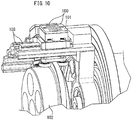
- FIG. 10 shows a portion of a device disclosed in WO2014/087293A1 .
- a plurality of units 100 each include a pad 101 for holding a side panel, and a rail 103 for guiding the pad 101 so that the pad 101 moves in the axial direction of a cam drum 102.
- Each unit 100 is guided by the cam drum 102 and the guide rail 103 to reciprocate in the axial direction, while rotating around the cam drum 102.
- panels held on the pads 101 are placed on the diaper body portion with a constant interval therebetween.
- the device of the present invention includes:
- the transmission mechanism is set to a first speed ratio when manufacturing a worn article of the first size; and the transmission mechanism is set to a second speed ratio different from the first speed ratio when manufacturing a worn article of the second size.
- the speed ratio (transmission ratio) of the transmission mechanism is changed when changing the size of the worn article to be manufactured.
- the speed ratio may be changed by changing the third pulley to another third pulley having a different diameter.
- the transmission mechanism is present (exists) between the second pulley and the third pulley, and changes a rotation speed of the third pulley with respect to a rotation speed of the second pulley, thereby changing the speed of reciprocation of the pad with respect to the speed of reciprocation of the mover.
- articles of different sizes can be manufactured only by changing the speed ratio of the transmission mechanism that is present between the second pulley and the third pulley, without changing (replacing) the second pulley and the third pulley themselves.
- the transmission mechanism includes:
- the method when changing the size of the worn article to be manufactured, the method further includes at least one of the step of changing the fifth pulley to another fifth pulley having a different diameter and the step of changing the sixth pulley to another sixth pulley having a different diameter.
- articles of different sizes can be manufactured by a simple operation of changing the fifth or sixth pulley to a pulley having a different diameter.
- the transmission mechanism further includes a seventh pulley that is placed on the same (an identical) axis with the fifth pulley and has a diameter different from the fifth pulley, or further includes a seventh pulley that is placed on the same (an identical) axis with the sixth pulley and has a diameter different from the sixth pulley.
- articles of different sizes can be manufactured by a very simple operation of re-winding the third belt, which has been wound around the fifth or sixth pulley, around the seventh pulley.
- the device further includes a tensioner for adjusting a tension of the third belt.
- the tension of the third belt can be set to an intended tension.
- the present diaper includes an absorbent body portion 20, and a pair of side panels (an example of sheet pieces) PL, PR and a pair of tab members 21, 21 attached to the body portion 20.
- the body portion 20 when worn, covers the front girth area, the crotch area and the rear girth area of the wearer.
- the body portion 20 includes a front torso portion 20f, a crotch portion 20c and a rear torso portion 20b corresponding respectively to these areas.
- the panels PL, PR When worn, the panels PL, PR are each located between the front and rear torso portions 20f, 20b in the girth direction X.
- the panels PL, PR are attached to the left side and the right side, respectively, of an end portion of the body portion 20 in the longitudinal direction Y.
- the panels PL, PR are attached to the rear torso portion 20b while protruding from the left side and the right side of the rear torso portion 20b of the body portion 20.
- the panels PL, PR may be attached to the front torso portion 20f.
- the tab members 21 are attached to the left side and the right side of the front torso portion 20f of the body portion 20. Note that the tab members 21 may be omitted.
- the panels PL, PR may be formed by providing elastic threads (an example of an elastic member) sandwiched between two sheets of a non-woven fabric, for example.
- the panels PL, PR may be in a shrunk state with gathers formed thereon, as the elastic threads shrink in the girth direction X, under no load.
- JPS63-243309A may be used as the method for placing elastic threads on the panels PL, PR.
- the panels PL, PR may be formed from a stretchable non-woven fabric having stretchability.
- a first touch fastener (an example of an attachment element) F1 may be attached to the inner surface side (the side to be in contact with the skin when worn) of the panels PL, PR.
- a second touch fastener (not shown) capable of being touch-fastened to the first touch fastener F1 may be attached to the outer surface side (the side to be exposed to the outside when worn) on the front torso portion 20f side of the body portion 20.
- the second touch fastener may be omitted.
- the body portion 20 and the panels ( PR, PL ) may be provided with an adhesive tape and an area where the adhesive tape is attached, respectively, instead of the touch fasteners.
- the body portion 20 may include, for example, a pair of cuffs (anti-leak walls) to be in contact with the surface of the wearer, a liquid-permeable top sheet, a liquid-absorbing absorbent core 24, a liquid-impermeable back sheet, etc.
- the body portion 20 may include, for example, leg elastic threads.
- the cuffs may be omitted, and elastic threads may be provided for shrinking the cuffs in the Y direction.
- the back sheet may be an air-permeable, waterproof sheet.
- the back sheet may be a stretchable sheet.
- the present manufacturing apparatus includes a first re-pitch drum 3, an interval-increasing drum (manufacturing device) 4, a first roller 51, a second roller 52 and a conveyer device (not shown).
- the re-pitch drum 3 receives panels (PL, PR) shown in FIG. 1 from a supply device (not shown).
- the supply device severs a continuous web W successively along cut-off lines C with alternating inclinations, as shown in FIG. 1 , thereby successively producing panels PL, PR.
- the virtual cut-off lines C may be non-parallel to the width direction X, and the tip portion of the continuous web W may be severed by a cutter (not shown) successively along the non-parallel cut-off lines C, thereby producing the panels PL, PR.
- the panels PL, PR may be trapezoidal, and the panels PL, PR may be shaped to be in point symmetry with each other about the point O on the center line CL.
- the shape of the panels PL, PR may be a parallelogram, a square or a rectangular.
- the first re-pitch drum 3 of FIG. 3A includes a plurality of left pads and right pads whose interval increases in the rotation direction (circumferential direction), and the pads then come closer to each other in the rotation direction.
- the interval (the distance between the panels) P0 in the flow direction Y between the panels PL, PR of FIG. 1 is increased to the interval P1.
- first re-pitch drum 3 may be the drum disclosed in US2006/0151093A1 or JPS63-317576A , whose disclosure is herein incorporated by reference in its entirety.
- the interval-increasing drum 4 of FIG. 3A includes a rotor 40 that is rotated, and a plurality of sets of link mechanisms 41 and a plurality of sets of interval-increasing units 1 ( FIG. 6A ) forming a part of the rotor 40.
- a first link 43 and a second link 44 of the link mechanism 41 rotate along cam grooves formed on the side surface of a cam drum 42, so that a plurality of sets of interval-increasing units 1, 1 ( FIG. 6A ) revolve at a periodically varying speed.
- the present interval-increasing drum 4 of FIG. 3A may be a second re-pitch drum.
- a plurality of sets of interval-increasing units 1 ( FIG. 6A ) revolve while the sets repeatedly come close to and move away from each other in the circumferential direction of the interval-increasing drum 4.
- the interval-increasing drum 4 successively receives panels from the first re-pitch drum 3, and hands over the panels alternately to the first and second rollers 51, 52.
- the interval-increasing drum 4 of FIG. 3A is placed downstream of the first re-pitch drum 3 to increase the interval (the distance) in the width direction X between a set of panels ( PL, PR ) adjacent to each other, of the plurality of panels (PL, PR) of FIG. 1 .
- the interval-increasing drum 4 may form a second re-pitch drum that increases the set-to-set interval P2 between (i) a set of panels PL, PR, which are separated from each other in the flow direction Y and (ii) another set of panels PL, PR adjacent to the separated set of panels.
- the interval-increasing drum 4 conceptually shown in FIG. 5 includes a plurality of left pads 4L and a plurality of right pads 4R. While the interval-increasing drum 4 makes one rotation, the interval in the width direction X between the pads 4L, 4R and the flow direction Y increase and then the pads 4L, 4R return to the original state.
- a step is performed, wherein the right pad 4R moves toward one side of the interval-increasing drum 4 and the left pad 4L moves toward the other side of the interval-increasing drum 4, thereby increasing the interval in the width direction X between the pad 4R and the pad 4L, while the interval-increasing drum 4 forming the second re-pitch drum increases the interval in the flow direction Y between pads 4R, 4R ( 4L, 4L ) that are adjacent to each other in the flow direction Y.
- the interval between panels PL, PL ( PR, PR ) that are adjacent to each other in the flow direction is increased from (2*P1) to P2.
- the width interval between the right and left pads 4R, 4L returns to the original state for the pads 4R, 4L to again receive the panels PL, PR, and the interval in the flow direction between the re-pitched pads also returns to the original interval.
- JP2006-230438A may be employed as the structure of the interval-increasing drum 4 described above, and the disclosure thereof is herein incorporated by reference in its entirety.
- the first and second rollers 51, 52 are placed downstream of the interval-increasing drum 4.
- the rollers 51, 52 place the set of panels PR, PL, respectively, of FIG. 2 on the body portion 20.
- the first and second rollers 51, 52 include first and second pads 51P, 52P for holding the panels PL, PR.
- the first pads 51P and the second pads 52P are placed away from each other in the width direction X.
- a cam groove 4C may be formed on the outer surface of the cam drum 42.
- the cam groove 4C is provided in a loop extending in the circumferential direction of the cam drum 42.
- a cam follower 1F of each interval-increasing unit 1 fits in the cam groove 4C.
- Each cam follower 1F is attached to a mover 1S.
- the mover 1S is guided along the cam groove 4C so as to reciprocate in the axial direction parallel to the axial line of the interval-increasing drum 4 by virtue of the rotation of the interval-increasing unit in the circumferential direction.
- the interval-increasing unit 1 shown in FIG. 7A rotatably supports first to seventh pulleys 11 to 17 on a frame 10. As shown in FIG. 3B , the frame 10 is provided for each interval-increasing unit 1 and rotates in the circumferential direction R of FIG. 3A .
- an endless first belt 1B is wound between the first pulley 11 and the second pulley 12.
- the first mover 1S is attached to the first belt 1B.
- an endless second belt 2B is wound between the third pulley 13 and the fourth pulley 14.
- a pair of second movers 2S, 2S of FIG. 6A is attached to the second belt 2B.
- the torque of the second pulley 12 is input to the fifth pulley 15 via a rotation shaft 18.
- An endless third belt 3B is wound between the fifth pulley 15 and the sixth pulley 16.
- the fifth pulley 15 and the seventh pulley 17 may be fixed on the same axis, and the third belt 3B is wound selectively around either the fifth pulley 15 or the seventh pulley 17, as shown in FIG. 7A and FIG. 7B .
- the sixth pulley 16 inputs its torque to the third pulley 13 via a rotation shaft 19.
- the fifth to seventh pulleys 15 to 17 and the third belt 3B together form a transmission mechanism SC.
- the transmission mechanism SC of this example is present between the second pulley 12 and the third pulley 13, and the transmission mechanism SC transmits the torque of the second pulley 12 to the third pulley 13 and changes the rotation speed of the third pulley 13 with respect to the rotation speed of the second pulley 12.
- each of the pulleys may be a toothed pulley.
- Each of the belts may be a timing belt.
- a pair of second movers 2S, 2S are attached to sides of the second belt 2B that are facing each other.
- the second movers 2S, 2S are attached respectively to the pads 4L, 4R, and are caused to reciprocate in opposite directions by the rotation of the pulleys and the belts, thereby reciprocating the pads 4L, 4R in opposite directions.
- Two pads 4L, 4R are attached to the frame 10 of FIG. 3B via two rails 1R and sliders 5R. Therefore, the pads 4L, 4R attached to the second movers 2S of FIG. 6A move in the axial direction X, while respectively holding the panels PL, PR thereon, in accordance with the reciprocation of the first mover 1S ( FIG. 7A ).
- Each of the first and fourth pulleys 11, 14 of FIG. 7A is individually rotatably supported on the frame 10.
- the second, fifth and seventh pulleys 12, 15, 17 are attached to one rotation shaft 18, and rotate in sync with each other at the same rotation speed (number of revolutions/min).
- the third and sixth pulleys are attached to one rotation shaft 19, and rotate in sync with each other at the same rotation speed.
- the second pulley 12 is caused to rotate by the rotation of the first belt 1B, which is caused by the reciprocation of the first mover 1S, and the rotation is transmitted to the fifth pulley 15.
- the rotation of the fifth pulley 15 is transmitted to the sixth pulley 16 via the third belt 3B, thereby rotating the third pulley 13 together with the shaft 19.
- a pair of pads 4L, 4R of FIG. 5 move in the axial direction X so as to move away from each other, while rotating in the circumferential direction R while holding the panels PL, PR, respectively. Note that the pads 4L, 4R come close to each other while rotating after handing over the panels to the rollers 51, 52 of FIG. 3A .
- the panels PL, PR held on a set of pads 4L, 4R come close to each other at a receiving position P11 of FIG. 3A and FIG. 6A , and significantly move away from each other in the axial direction X at a hand-over position P21 of FIG. 3A and FIG. 6A .
- the pads 4L, 4R which were away from each other in the axial direction X at the hand-over position P21 of FIG. 6A , come close to each other as they are at the receiving position P11.
- the second and third belts 2B, 3B of FIG. 6A are provided with tensioners 2T, 3T for adjusting the tensions of the belts 2B, 3B, respectively.
- the manufacturing method of the present embodiment may include a severing step, a first re-pitch step, an interval-increasing step, a second re-pitch step, a receiving step and a placement step to be described below.
- the tip portion in the flow direction Y of the continuous web W which is continuous in the flow direction Y, is severed by a cutter (not shown) successively along the virtual cut-off line C extending in the width direction X, thereby successively producing a plurality of panels PL, PR.
- the panels PL, PR produced by the severing are received by the first re-pitch drum 3 ( FIG. 3A ), and then the interval therebetween in the flow direction Y of FIG. 1 is increased from P0 to P1 of FIG. 1 .
- the first re-pitch step is performed.
- the panels PL, PR of FIG. 1 are handed over from the first re-pitch drum 3 to the interval-increasing drum 4 of FIG. 3A .
- the interval in the width direction X between a set of panels PL, PR, adjacent to each other, of the plurality of panels PL, PR of FIG. 1 is increased.
- the interval-increasing step is performed.
- the second re-pitch step of increasing the set-to-set interval between a set of panels PL, PR and another, adjacent set of panels PL, PR, which are separated from each other in the flow direction Y may be performed. That is, the interval between panels PR ( PL ) that are adjacent to each other in the flow direction Y may be increased to P2.
- phase shift of the pitch P1 of FIG. 1 is present between the set of panels PL, PR.
- the receiving step of receiving, on the first and second rollers 51, 52, the panels PL, PR from the interval-increasing drum 4 of FIG. 3A is performed.
- a step of placing each of the set of panels PR, PL of FIG. 2 on the body portion 20 is performed. That is, after the receiving step, the placement step shown in FIG. 2 is performed. In this placement step, the panels PL, PR from the first and second rollers 51, 52 ( FIG. 5 ) are placed on opposite sides of the body portion 20. Note that the details of the placement step are disclosed in WO2013/157533A1 ( US9,265,670B2 ), supra, and the disclosure thereof is herein incorporated by reference in its entirety.
- FIG. 2 shows a diaper of a first, small size
- FIG. 8 shows a diaper of a second, large size.
- the set-to-set interval P2 of the diaper of the second size of FIG. 8 may be greater than or equal to the set-to-set interval P2 of the diaper of the first size of FIG. 2 .
- the distance in the width direction X between the panels PL, PR of the diaper of the second size of FIG. 8 is greater than the distance in the width direction X between the panels PL, PR of the diaper of the first size of FIG. 2 .
- the diameter of the fifth pulley 15 is smaller than the diameter of the seventh pulley 17, for example.
- the second speed ratio of the sixth pulley with respect to the seventh pulley 17 is greater than the first speed ratio of the sixth pulley with respect to the fifth pulley 15.
- the transmission mechanism SC is set to the first speed ratio as shown in FIG. 6A . Then, the tension of the third belt 3B is adjusted by the tensioner 3T ( FIG. 6A ). Thereafter, the diaper of the first size is manufactured by a method similar to that described above.
- the transmission mechanism SC is set to the second speed ratio as shown in FIG. 6B . Then, the tension of the third belt 3B is adjusted by the tensioner 3T ( FIG. 6A ). Thereafter, the diaper of the second size is manufactured by a method similar to that described above.
- the speed ratio is changed by first operating the tensioner 3T of FIG. 6A to slack the tension of the third belt, and moving the third belt 3B in the axial direction of the shafts 18, 19 so that the third belt 3B is wound between the sixth pulley 16 and the seventh pulley 17 as shown in FIG. 7B , without removing the transmission mechanism SC of FIG. 7A from the unit 1. Then, the tensioner 3T of FIG. 6B is operated to adjust the tension of the third belt 3B.
- FIG. 9A and FIG. 9B show another example of the transmission mechanism SC.
- the fifth pulley 15 placed on the same axis with the second pulley 12 is elongated in the axial direction.
- the third belt 3B is wound between either the sixth pulley 16 or the seventh pulley 17 and the fifth pulley 15.
- FIG. 9C and FIG. 9D show still another example.
- the fifth pulley 15 and the sixth pulley 16 have different diameters from each other. Therefore, the rotation speed of the second pulley 12 is changed by the transmission mechanism SC to a speed that is different from the rotation speed of the third pulley 13.
- the speed ratio is set to the first speed ratio when manufacturing a diaper of the first, small size, and to the second speed ratio when manufacturing a diaper of the second, large size.
- the transmission mechanism may be used to increase the interval between web pieces other than side panels.
- the transmission mechanism may be implemented by a combination of gears, instead of belts and pulleys.
- the worn article may be of a diaper type or a pants type.
- the present invention is applicable to a method for manufacturing a disposable worn article, and to manufacturing of a device for manufacturing the same.
Landscapes
- Engineering & Computer Science (AREA)
- Health & Medical Sciences (AREA)
- General Engineering & Computer Science (AREA)
- Vascular Medicine (AREA)
- Biomedical Technology (AREA)
- Heart & Thoracic Surgery (AREA)
- Epidemiology (AREA)
- Life Sciences & Earth Sciences (AREA)
- Animal Behavior & Ethology (AREA)
- General Health & Medical Sciences (AREA)
- Public Health (AREA)
- Veterinary Medicine (AREA)
- Manufacturing & Machinery (AREA)
- Mechanical Engineering (AREA)
- Absorbent Articles And Supports Therefor (AREA)
Abstract

Description
- The present invention relates to a method and a device for manufacturing a disposable worn article.
- As a device for manufacturing a worn article of this type, devices for attaching a set of panels on the left side and the right side in the girth direction of the body portion of the diaper (the first and second patent documents) are known in the art. Also, a rotor including a plurality of units that rotate around a cam drum is known in the art (the third patent document).
-
- [First Patent Document]
JP2010-530269A FIGS. 1 to 6 ) - [Second Patent Document]
WO2013/157533A1 (FIG. 1 ) - [Third Patent Document]
US9,265,670B2 FIG. 1 ) - [Fourth Patent Document]
WO2014/087293A1 (FIGS. 3 ,9 ) -
FIG. 10 shows a portion of a device disclosed inWO2014/087293A1 . In this figure, a plurality ofunits 100 each include apad 101 for holding a side panel, and arail 103 for guiding thepad 101 so that thepad 101 moves in the axial direction of acam drum 102. Eachunit 100 is guided by thecam drum 102 and theguide rail 103 to reciprocate in the axial direction, while rotating around thecam drum 102. Thus, panels held on thepads 101 are placed on the diaper body portion with a constant interval therebetween. - However, there are diapers of different sizes. Diapers of different sizes have different distances between a pair of, left and right, panels. When manufacturing diapers of different sizes, it is necessary, with the conventional technique described above, to replace the cam drum. Thus, changing the size is troublesome and costly.
- Even where only one type of a standard size is manufactured, a similar problem will occur when there is a change to the standard size itself.
- It is an object of the present invention to provide a device and a method for manufacturing different types of disposable worn article having different sizes, without replacing the cam drum.
- The device of the present invention includes:
- a cam drum; and
- a rotor that is rotated around the cam drum, wherein:
- the rotor includes a plurality of units; and
- each of the units includes:
- a mover that is guided by the cam drum and reciprocates in an axial direction parallel to an axial line of the cam drum by virtue of the rotation of the rotor (i.e., while the rotor rotates);
- a first belt linked to the mover;
- a first pulley and a second pulley between which the first belt is wound and which rotate together with the first belt;
- a pad that reciprocates in the axial direction in accordance with the reciprocation of the mover, while holding a sheet piece, which is a part of the worn article;
- a second belt linked to the pad;
- a third pulley and a fourth pulley between which the second belt is wound and which rotate together with the second belt; and
- a transmission (speed-changing) mechanism that transmits the rotation of the second pulley to the third pulley and changes a speed of reciprocation of the pad with respect to a speed of reciprocation of the mover.
- Where worn articles of a first size and a second size are manufactured using the device of the present invention,
the transmission mechanism is set to a first speed ratio when manufacturing a worn article of the first size; and
the transmission mechanism is set to a second speed ratio different from the first speed ratio when manufacturing a worn article of the second size. - That is, the speed ratio (transmission ratio) of the transmission mechanism is changed when changing the size of the worn article to be manufactured.
- For example, the speed ratio may be changed by changing the third pulley to another third pulley having a different diameter.
- According to the present invention, it is possible to manufacture different disposable worn articles of different sizes without replacing the cam drum. Therefore, changing the size is neither troublesome nor costly.
-
-
FIG. 1 is a conceptual diagram showing a method for manufacturing a worn article of the present invention, showing a part of a step of manufacturing a diaper of a first size. -
FIG. 2 is a conceptual diagram showing the rest of the same step. -
FIG. 3A is a schematic side view showing a manufacturing device of the present invention, andFIG. 3B is a front view of a unit. -
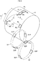
FIG. 4 is a schematic side view showing a cam drum. -
FIG. 5 is a conceptual perspective view showing an interval-increasing drum, a first roller and a second roller. -
FIG. 6A and FIG. 6B are plan views showing a unit when manufacturing an article of a first size and an article of a second size, respectively. -
FIG. 7A and FIG. 7B are side views of the unit when manufacturing an article of the first size and an article of the second size, respectively. -
FIG. 8 is a conceptual diagram showing a diaper of the second size and a part of a method for manufacturing the same. -
FIG. 9A and FIG. 9B are side views showing alternative examples of a transmission mechanism, andFIG. 9C and FIG. 9D are side views showing other alternative examples of the transmission mechanism. -
FIG. 10 is a perspective view showing a part of a manufacturing device known in the art. - Preferably, the transmission mechanism is present (exists) between the second pulley and the third pulley, and changes a rotation speed of the third pulley with respect to a rotation speed of the second pulley, thereby changing the speed of reciprocation of the pad with respect to the speed of reciprocation of the mover.
- In this case, articles of different sizes can be manufactured only by changing the speed ratio of the transmission mechanism that is present between the second pulley and the third pulley, without changing (replacing) the second pulley and the third pulley themselves.
- Preferably, the transmission mechanism includes:
- a fifth pulley to which a torque of the second pulley is input;
- an endless third belt that is wound around the fifth pulley and is driven by the rotation of the fifth pulley; and
- a sixth pulley around which the third belt is wound, which is rotated by the rotation of the third belt, and which inputs a torque thereof (i.e., of the sixth pulley) to the third pulley.
- In this case, when changing the size of the worn article to be manufactured, the method further includes at least one of the step of changing the fifth pulley to another fifth pulley having a different diameter and the step of changing the sixth pulley to another sixth pulley having a different diameter.
- In this case, articles of different sizes can be manufactured by a simple operation of changing the fifth or sixth pulley to a pulley having a different diameter.
- Preferably, the transmission mechanism further includes a seventh pulley that is placed on the same (an identical) axis with the fifth pulley and has a diameter different from the fifth pulley, or further includes a seventh pulley that is placed on the same (an identical) axis with the sixth pulley and has a diameter different from the sixth pulley.
- In this case, articles of different sizes can be manufactured by a very simple operation of re-winding the third belt, which has been wound around the fifth or sixth pulley, around the seventh pulley.
- Preferably, the device further includes a tensioner for adjusting a tension of the third belt.
- In this case, even when the third belt is re-wound around a pulley having a different diameter, the tension of the third belt can be set to an intended tension.
- Any feature illustrated and/or depicted in conjunction with one of the aforementioned aspects or the following embodiments may be used in the same or similar form in one or more of the other aspects or other embodiments, and/or may be used in combination with, or in place of, any feature of the other aspects or embodiments.
- The present invention will be understood more clearly from the following description of preferred embodiments taken in conjunction with the accompanying drawings. Note however that the embodiments and the drawings are merely illustrative and should not be taken to define the scope of the present invention. The scope of the present invention shall be defined only by the appended claims. In the accompanying drawings, like reference numerals denote like components throughout the plurality of figures.
- An embodiment of the present invention will now be described with reference to the drawings.
- First, before describing a manufacturing method and a manufacturing device of the present invention, an example of a worn article that can be manufactured by the present manufacturing method will be described.
- As shown in
FIG. 2 , the present diaper includes anabsorbent body portion 20, and a pair of side panels (an example of sheet pieces) PL, PR and a pair oftab members body portion 20. - The
body portion 20, when worn, covers the front girth area, the crotch area and the rear girth area of the wearer. Thebody portion 20 includes afront torso portion 20f, acrotch portion 20c and arear torso portion 20b corresponding respectively to these areas. - When worn, the panels PL, PR are each located between the front and
rear torso portions body portion 20 in the longitudinal direction Y. For example, the panels PL, PR are attached to therear torso portion 20b while protruding from the left side and the right side of therear torso portion 20b of thebody portion 20. Note that the panels PL, PR may be attached to thefront torso portion 20f. - On the other hand, the
tab members 21 are attached to the left side and the right side of thefront torso portion 20f of thebody portion 20. Note that thetab members 21 may be omitted. - The panels PL, PR may be formed by providing elastic threads (an example of an elastic member) sandwiched between two sheets of a non-woven fabric, for example. The panels PL, PR may be in a shrunk state with gathers formed thereon, as the elastic threads shrink in the girth direction X, under no load.
- Note that the method disclosed in JPS63-243309A may be used as the method for placing elastic threads on the panels PL, PR.
- Instead of using elastic threads, the panels PL, PR may be formed from a stretchable non-woven fabric having stretchability.
- A first touch fastener (an example of an attachment element) F1 may be attached to the inner surface side (the side to be in contact with the skin when worn) of the panels PL, PR. On the other hand, a second touch fastener (not shown) capable of being touch-fastened to the first touch fastener F1 may be attached to the outer surface side (the side to be exposed to the outside when worn) on the
front torso portion 20f side of thebody portion 20. When wearing the present diaper, one puts the side panels PL, PR around the torso of the wearer while holding thetab members 21, and attaches the first touch fasteners F1 of the side panels PL, PR to the second touch fastener, thus putting the present diaper on the wearer. - Note that if the outer surface side of the
body portion 20 is formed from a material to which the first touch fastener F1 can be attached, the second touch fastener may be omitted. Thebody portion 20 and the panels (PR, PL) may be provided with an adhesive tape and an area where the adhesive tape is attached, respectively, instead of the touch fasteners. - The
body portion 20 may include, for example, a pair of cuffs (anti-leak walls) to be in contact with the surface of the wearer, a liquid-permeable top sheet, a liquid-absorbingabsorbent core 24, a liquid-impermeable back sheet, etc. - Note that the
body portion 20 may include, for example, leg elastic threads. Moreover, the cuffs may be omitted, and elastic threads may be provided for shrinking the cuffs in the Y direction. The back sheet may be an air-permeable, waterproof sheet. The back sheet may be a stretchable sheet. - Next, a part of an example of a manufacturing apparatus will be described.
- As shown in
FIG. 3A , the present manufacturing apparatus includes a firstre-pitch drum 3, an interval-increasing drum (manufacturing device) 4, afirst roller 51, asecond roller 52 and a conveyer device (not shown). - The
re-pitch drum 3 receives panels (PL, PR) shown inFIG. 1 from a supply device (not shown). The supply device (not shown) severs a continuous web W successively along cut-off lines C with alternating inclinations, as shown inFIG. 1 , thereby successively producing panels PL, PR. - The virtual cut-off lines C may be non-parallel to the width direction X, and the tip portion of the continuous web W may be severed by a cutter (not shown) successively along the non-parallel cut-off lines C, thereby producing the panels PL, PR. For example, the panels PL, PR may be trapezoidal, and the panels PL, PR may be shaped to be in point symmetry with each other about the point O on the center line CL. The shape of the panels PL, PR may be a parallelogram, a square or a rectangular.
- The first
re-pitch drum 3 ofFIG. 3A includes a plurality of left pads and right pads whose interval increases in the rotation direction (circumferential direction), and the pads then come closer to each other in the rotation direction. After receiving the panels (PL, PR) by the first re-pitch drum well known in the art, the interval (the distance between the panels) P0 in the flow direction Y between the panels PL, PR ofFIG. 1 is increased to the interval P1. - Note that the first
re-pitch drum 3 may be the drum disclosed inUS2006/0151093A1 orJPS63-317576A - The interval-increasing
drum 4 ofFIG. 3A includes arotor 40 that is rotated, and a plurality of sets oflink mechanisms 41 and a plurality of sets of interval-increasing units 1 (FIG. 6A ) forming a part of therotor 40. - With the present interval-increasing
drum 4, afirst link 43 and a second link 44 of thelink mechanism 41 rotate along cam grooves formed on the side surface of acam drum 42, so that a plurality of sets of interval-increasingunits 1, 1 (FIG. 6A ) revolve at a periodically varying speed. - That is, the present interval-increasing
drum 4 ofFIG. 3A may be a second re-pitch drum. A plurality of sets of interval-increasing units 1 (FIG. 6A ) revolve while the sets repeatedly come close to and move away from each other in the circumferential direction of the interval-increasingdrum 4. Note that in this example, the interval-increasingdrum 4 successively receives panels from the firstre-pitch drum 3, and hands over the panels alternately to the first andsecond rollers - The interval-increasing
drum 4 ofFIG. 3A is placed downstream of the firstre-pitch drum 3 to increase the interval (the distance) in the width direction X between a set of panels (PL, PR) adjacent to each other, of the plurality of panels (PL, PR) ofFIG. 1 . The interval-increasingdrum 4 may form a second re-pitch drum that increases the set-to-set interval P2 between (i) a set of panels PL, PR, which are separated from each other in the flow direction Y and (ii) another set of panels PL, PR adjacent to the separated set of panels. - The interval-increasing
drum 4 conceptually shown inFIG. 5 includes a plurality ofleft pads 4L and a plurality ofright pads 4R. While the interval-increasingdrum 4 makes one rotation, the interval in the width direction X between thepads pads - That is, as the interval-increasing
drum 4 rotates in the circumferential direction R, a step is performed, wherein theright pad 4R moves toward one side of the interval-increasingdrum 4 and theleft pad 4L moves toward the other side of the interval-increasingdrum 4, thereby increasing the interval in the width direction X between thepad 4R and thepad 4L, while the interval-increasingdrum 4 forming the second re-pitch drum increases the interval in the flow direction Y betweenpads FIG. 1 , the interval between panels PL, PL (PR, PR) that are adjacent to each other in the flow direction is increased from (2*P1) to P2. - In the placement step to be described below, after the
pads FIG. 5 hand over the panels PL, PR to the first andsecond rollers pads pads - The structure of a drum disclosed in
JP2006-230438A drum 4 described above, and the disclosure thereof is herein incorporated by reference in its entirety. - In
FIG. 3A , the first andsecond rollers drum 4. Therollers FIG. 2 on thebody portion 20. - As shown in
FIG. 5 , the first andsecond rollers second pads first pads 51P and thesecond pads 52P are placed away from each other in the width direction X. - Note that the details of the structure of the first and
second rollers WO2013/157533A1 , supra, and the disclosure thereof is herein incorporated by reference in its entirety. - Next, the interval-increasing mechanism of the present interval-increasing
drum 4 will be described. - As shown in
FIG. 4 , a cam groove 4C may be formed on the outer surface of thecam drum 42. The cam groove 4C is provided in a loop extending in the circumferential direction of thecam drum 42. - A
cam follower 1F of each interval-increasing unit 1 (FIG. 3A ) fits in the cam groove 4C. Eachcam follower 1F is attached to amover 1S. Themover 1S is guided along the cam groove 4C so as to reciprocate in the axial direction parallel to the axial line of the interval-increasingdrum 4 by virtue of the rotation of the interval-increasing unit in the circumferential direction. - The interval-increasing
unit 1 shown inFIG. 7A rotatably supports first toseventh pulleys 11 to 17 on aframe 10. As shown inFIG. 3B , theframe 10 is provided for each interval-increasingunit 1 and rotates in the circumferential direction R ofFIG. 3A . - On one side of the
frame 10 ofFIG. 7A , an endlessfirst belt 1B is wound between thefirst pulley 11 and thesecond pulley 12. Thefirst mover 1S is attached to thefirst belt 1B. - On the other side of the
frame 10 ofFIG. 7A , an endlesssecond belt 2B is wound between thethird pulley 13 and thefourth pulley 14. A pair ofsecond movers FIG. 6A is attached to thesecond belt 2B. - In
FIG. 7A , the torque of thesecond pulley 12 is input to thefifth pulley 15 via arotation shaft 18. An endlessthird belt 3B is wound between thefifth pulley 15 and thesixth pulley 16. Thefifth pulley 15 and theseventh pulley 17 may be fixed on the same axis, and thethird belt 3B is wound selectively around either thefifth pulley 15 or theseventh pulley 17, as shown inFIG. 7A and FIG. 7B . Thesixth pulley 16 inputs its torque to thethird pulley 13 via arotation shaft 19. - That is, in the present embodiment, the fifth to
seventh pulleys 15 to 17 and thethird belt 3B together form a transmission mechanism SC. The transmission mechanism SC of this example is present between thesecond pulley 12 and thethird pulley 13, and the transmission mechanism SC transmits the torque of thesecond pulley 12 to thethird pulley 13 and changes the rotation speed of thethird pulley 13 with respect to the rotation speed of thesecond pulley 12. - Note that each of the pulleys may be a toothed pulley. Each of the belts may be a timing belt.
- As shown in
FIG. 6A , a pair ofsecond movers second belt 2B that are facing each other. Thesecond movers pads pads - Two
pads frame 10 ofFIG. 3B via tworails 1R andsliders 5R. Therefore, thepads second movers 2S ofFIG. 6A move in the axial direction X, while respectively holding the panels PL, PR thereon, in accordance with the reciprocation of thefirst mover 1S (FIG. 7A ). - Each of the first and
fourth pulleys FIG. 7A is individually rotatably supported on theframe 10. The second, fifth andseventh pulleys rotation shaft 18, and rotate in sync with each other at the same rotation speed (number of revolutions/min). The third and sixth pulleys are attached to onerotation shaft 19, and rotate in sync with each other at the same rotation speed. - The
second pulley 12 is caused to rotate by the rotation of thefirst belt 1B, which is caused by the reciprocation of thefirst mover 1S, and the rotation is transmitted to thefifth pulley 15. The rotation of thefifth pulley 15 is transmitted to thesixth pulley 16 via thethird belt 3B, thereby rotating thethird pulley 13 together with theshaft 19. - As the
second belt 2B is rotated by the rotation of thethird pulley 13 ofFIG. 6A , a pair ofpads second movers 2S. - Thus, a pair of
pads FIG. 5 move in the axial direction X so as to move away from each other, while rotating in the circumferential direction R while holding the panels PL, PR, respectively. Note that thepads rollers FIG. 3A . - That is, the panels PL, PR held on a set of
pads FIG. 3A andFIG. 6A , and significantly move away from each other in the axial direction X at a hand-over position P21 ofFIG. 3A andFIG. 6A . Note that by rotating from the hand-over position P21 to the receiving position P11 ofFIG. 3A , thepads FIG. 6A , come close to each other as they are at the receiving position P11. - The second and
third belts FIG. 6A are provided withtensioners belts - Next, an example of a method for manufacturing a diaper of a particular size will be described.
- The manufacturing method of the present embodiment may include a severing step, a first re-pitch step, an interval-increasing step, a second re-pitch step, a receiving step and a placement step to be described below.
- As shown in
FIG. 1 , in the severing step, the tip portion in the flow direction Y of the continuous web W, which is continuous in the flow direction Y, is severed by a cutter (not shown) successively along the virtual cut-off line C extending in the width direction X, thereby successively producing a plurality of panels PL, PR. The panels PL, PR produced by the severing are received by the first re-pitch drum 3 (FIG. 3A ), and then the interval therebetween in the flow direction Y ofFIG. 1 is increased from P0 to P1 ofFIG. 1 . Thus, the first re-pitch step is performed. - After the first re-pitch step, the panels PL, PR of
FIG. 1 are handed over from the firstre-pitch drum 3 to the interval-increasingdrum 4 ofFIG. 3A . On the interval-increasingdrum 4, the interval in the width direction X between a set of panels PL, PR, adjacent to each other, of the plurality of panels PL, PR ofFIG. 1 is increased. Thus, the interval-increasing step is performed. - At the same time with the interval-increasing step, the second re-pitch step of increasing the set-to-set interval between a set of panels PL, PR and another, adjacent set of panels PL, PR, which are separated from each other in the flow direction Y may be performed. That is, the interval between panels PR (PL) that are adjacent to each other in the flow direction Y may be increased to P2.
- In this process, a phase shift (phase difference) of the pitch P1 of
FIG. 1 is present between the set of panels PL, PR. - After the interval-increasing step and the second re-pitch step, the receiving step of receiving, on the first and
second rollers drum 4 ofFIG. 3A is performed. Moreover, a step of placing each of the set of panels PR, PL ofFIG. 2 on thebody portion 20 is performed. That is, after the receiving step, the placement step shown inFIG. 2 is performed. In this placement step, the panels PL, PR from the first andsecond rollers 51, 52 (FIG. 5 ) are placed on opposite sides of thebody portion 20. Note that the details of the placement step are disclosed inWO2013/157533A1 (US9,265,670B2 - Next, a case where there is a change to the size of the worn article to be manufactured will be described.
-
FIG. 2 shows a diaper of a first, small size, whereasFIG. 8 shows a diaper of a second, large size. - The set-to-set interval P2 of the diaper of the second size of
FIG. 8 may be greater than or equal to the set-to-set interval P2 of the diaper of the first size ofFIG. 2 . - The distance in the width direction X between the panels PL, PR of the diaper of the second size of
FIG. 8 is greater than the distance in the width direction X between the panels PL, PR of the diaper of the first size ofFIG. 2 . - In
FIG. 7A , in the present embodiment, the diameter of thefifth pulley 15 is smaller than the diameter of theseventh pulley 17, for example. The second speed ratio of the sixth pulley with respect to theseventh pulley 17 is greater than the first speed ratio of the sixth pulley with respect to thefifth pulley 15. - Therefore, when manufacturing a diaper of the first, small size, a setting is used in which the
third belt 3B is wound between thefifth pulley 15 and thesixth pulley 16 as shown inFIG. 7A . On the other hand, when manufacturing a diaper of the second, large size, a setting is used in which thethird belt 3B is wound between theseventh pulley 17 and thesixth pulley 16 as shown inFIG. 7B . - When manufacturing a diaper of the first size, the transmission mechanism SC is set to the first speed ratio as shown in
FIG. 6A . Then, the tension of thethird belt 3B is adjusted by thetensioner 3T (FIG. 6A ). Thereafter, the diaper of the first size is manufactured by a method similar to that described above. - When manufacturing a diaper of the second size, the transmission mechanism SC is set to the second speed ratio as shown in
FIG. 6B . Then, the tension of thethird belt 3B is adjusted by thetensioner 3T (FIG. 6A ). Thereafter, the diaper of the second size is manufactured by a method similar to that described above. - In the present embodiment, the speed ratio is changed by first operating the
tensioner 3T ofFIG. 6A to slack the tension of the third belt, and moving thethird belt 3B in the axial direction of theshafts third belt 3B is wound between thesixth pulley 16 and theseventh pulley 17 as shown inFIG. 7B , without removing the transmission mechanism SC ofFIG. 7A from theunit 1. Then, thetensioner 3T ofFIG. 6B is operated to adjust the tension of thethird belt 3B. -
FIG. 9A and FIG. 9B show another example of the transmission mechanism SC. - In these figures, the
fifth pulley 15 placed on the same axis with thesecond pulley 12 is elongated in the axial direction. Thethird belt 3B is wound between either thesixth pulley 16 or theseventh pulley 17 and thefifth pulley 15. -
FIG. 9C and FIG. 9D show still another example. - In these figures, the
fifth pulley 15 and thesixth pulley 16 have different diameters from each other. Therefore, the rotation speed of thesecond pulley 12 is changed by the transmission mechanism SC to a speed that is different from the rotation speed of thethird pulley 13. - When changing the size, the fifth and
sixth pulleys FIG. 9C are switched around as shown inFIG. 9D . That is, the speed ratio is set to the first speed ratio when manufacturing a diaper of the first, small size, and to the second speed ratio when manufacturing a diaper of the second, large size. - Note that in this example, only one of the fifth and sixth pulleys may be changed to a pulley of a different diameter.
- While preferred embodiments have been described above with reference to the drawings, obvious variations and modifications will readily occur to those skilled in the art upon reading the present specification.
- For example, the transmission mechanism may be used to increase the interval between web pieces other than side panels.
- The transmission mechanism may be implemented by a combination of gears, instead of belts and pulleys.
- The worn article may be of a diaper type or a pants type.
- Thus, such changes and modifications are deemed to fall within the scope of the present invention, which is defined by the appended claims.
- The present invention is applicable to a method for manufacturing a disposable worn article, and to manufacturing of a device for manufacturing the same.
-
- 1: Interval-increasing unit, 1B: First belt, 1S: First mover
- 10: Frame, 11 to 17: First to seventh pulleys
- 2B: Second belt, 2S: Second mover
- 20: Absorbent body portion, 20b: Rear torso portion, 20c: Crotch portion, 20f: Front torso portion
- 21: Tab member
- 3: First re-pitch drum, 3B: Third belt, 2T, 3T: Tensioner
- 4: Interval-increasing drum (second re-pitch drum), 4L, 4R: Left and right pads
- 40: Rotor, 41: Link mechanism, 42: Cam drum, 43, 44: Link
- 5R: Slider
- 51, 52: First and second rollers
- 51P, 52P: First and second pads
- C: Cut-off line, CL: Center line
- F1: First touch fastener
- PL, PR: Side panel (sheet piece)
- P1, P1: Interval, P2: Set-to-set interval, P11: Receiving position
- P21: Hand-over position
- SC: Transmission mechanism
- X: Width direction (axial direction), Y: Flow direction
- W: Continuous web
Claims (8)
- A device for manufacturing a disposable worn article, the device comprising:a cam drum; anda rotor that is rotated around the cam drum, wherein:the rotor includes a plurality of units; andeach of the units includes:a mover that is guided by the cam drum and reciprocates in an axial direction parallel to an axial line of the cam drum by virtue of the rotation of the rotor;a first belt linked to the mover;a first pulley and a second pulley between which the first belt is wound and which rotate together with the first belt;a pad that reciprocates in the axial direction in accordance with the reciprocation of the mover, while holding a sheet piece, which is a part of the worn article;a second belt linked to the pad;a third pulley and a fourth pulley between which the second belt is wound and which rotate together with the second belt; anda transmission mechanism that transmits the rotation of the second pulley to the third pulley and changes a speed of reciprocation of the pad with respect to a speed of reciprocation of the mover.
- The device for manufacturing a disposable worn article according to claim 1, wherein the transmission mechanism is present between the second pulley and the third pulley, and changes a rotation speed of the third pulley with respect to a rotation speed of the second pulley, thereby changing the speed of reciprocation of the pad with respect to the speed of reciprocation of the mover.
- The device for manufacturing a disposable worn article according to claim 2, wherein the transmission mechanism comprises:a fifth pulley to which a torque of the second pulley is input;an endless third belt that is wound around the fifth pulley and is driven by the rotation of the fifth pulley; anda sixth pulley around which the third belt is wound, which is rotated by the rotation of the third belt, and which inputs a torque thereof to the third pulley.
- The device for manufacturing a disposable worn article according to claim 3, wherein the transmission mechanism further comprises at least one of a seventh pulley that is placed on the same axis with the fifth pulley and has a diameter different from the fifth pulley, and a seventh pulley that is placed on the same axis with the sixth pulley and has a diameter different from the sixth pulley.
- The device for manufacturing a disposable worn article according to claim 3 or 4, further comprising a tensioner for adjusting a tension of the third belt.
- A disposable worn article manufacturing method for manufacturing worn articles of a first size and a second size by using the manufacturing device according to claim 1 or 2, the method comprising the steps of:setting the transmission mechanism to a first speed ratio when manufacturing a worn article of the first size; andsetting the transmission mechanism to a second speed ratio different from the first speed ratio when manufacturing a worn article of the second size.
- A disposable worn article manufacturing method for manufacturing worn articles of a first size and a second size by using the manufacturing device according to claim 1 or 2, the method comprising the step of changing a speed ratio of the transmission mechanism when changing a size of the worn article to be manufactured.
- A disposable worn article manufacturing method for manufacturing worn articles of a first size and a second size by using the manufacturing device according to claim 3, the method further comprising:
when changing a size of the worn article to be manufactured, at least one of the step of changing the fifth pulley to another fifth pulley having a different diameter and the step of changing the sixth pulley to another sixth pulley having a different diameter.
Applications Claiming Priority (2)
| Application Number | Priority Date | Filing Date | Title |
|---|---|---|---|
| JP2015191499 | 2015-09-29 | ||
| PCT/JP2016/076846 WO2017056952A1 (en) | 2015-09-29 | 2016-09-12 | Manufacturing device and manufacturing method for disposable wearable articles |
Publications (3)
| Publication Number | Publication Date |
|---|---|
| EP3357463A1 true EP3357463A1 (en) | 2018-08-08 |
| EP3357463A4 EP3357463A4 (en) | 2019-04-03 |
| EP3357463B1 EP3357463B1 (en) | 2020-01-01 |
Family
ID=58427449
Family Applications (1)
| Application Number | Title | Priority Date | Filing Date |
|---|---|---|---|
| EP16851126.9A Active EP3357463B1 (en) | 2015-09-29 | 2016-09-12 | Manufacturing device and manufacturing method for disposable wearable articles |
Country Status (5)
| Country | Link |
|---|---|
| US (1) | US10206822B2 (en) |
| EP (1) | EP3357463B1 (en) |
| JP (1) | JP6698672B2 (en) |
| CN (1) | CN107949357B (en) |
| WO (1) | WO2017056952A1 (en) |
Cited By (1)
| Publication number | Priority date | Publication date | Assignee | Title |
|---|---|---|---|---|
| EP3907637A1 (en) | 2020-05-05 | 2021-11-10 | Siemens Aktiengesellschaft | Method and device for securely starting a container instance |
Families Citing this family (5)
| Publication number | Priority date | Publication date | Assignee | Title |
|---|---|---|---|---|
| CN108679178B (en) * | 2018-08-14 | 2023-06-20 | 晋江海纳机械有限公司 | Rubber band traction device and system |
| JP7277583B2 (en) * | 2019-06-11 | 2023-05-19 | 株式会社瑞光 | Conveying device and method |
| CN112704596B (en) * | 2020-12-30 | 2021-11-02 | 泉州市汉威机械制造有限公司 | Novel paper diaper trousers ear sticker turning and distance changing device |
| IT202300009093A1 (en) * | 2023-05-08 | 2024-11-08 | Gdm Spa | MACHINE AND METHOD FOR THE MANUFACTURE OF HYGIENIC ABSORBENT ARTICLES |
| KR20250121797A (en) * | 2024-02-05 | 2025-08-12 | 주식회사 엘지에너지솔루션 | Rotary transfer device |
Family Cites Families (14)
| Publication number | Priority date | Publication date | Assignee | Title |
|---|---|---|---|---|
| US3333574A (en) * | 1966-11-29 | 1967-08-01 | Samuel D Harris | Method of and device for feeding animals |
| US5025910A (en) * | 1990-02-02 | 1991-06-25 | Curt G. Joa, Inc. | Rotary pad turner |
| JP3798298B2 (en) * | 2000-12-01 | 2006-07-19 | 株式会社瑞光 | Rotating device, method for conveying worn article, and method for conveying web |
| US6913664B2 (en) * | 2001-05-23 | 2005-07-05 | Zuiko Corporation | Method and apparatus for producing disposable worn article |
| US6742646B2 (en) * | 2001-09-28 | 2004-06-01 | Mcneil-Ppc, Inc. | Systems, methods and apparatuses for manufacturing dosage forms |
| EP1591273B1 (en) * | 2004-04-26 | 2008-08-20 | Müller Martini Holding AG | Apparatus for transferring book blocks to intermittent processing |
| ES2922456T3 (en) * | 2007-02-21 | 2022-09-15 | Joa Curt G Inc | Simple transfer insert placement method and apparatus |
| ITBO20070431A1 (en) | 2007-06-19 | 2008-12-20 | Gdm Spa | MACHINE AND METHOD FOR THE CONSTRUCTION OF ABSORBENT ITEMS. |
| JP5838024B2 (en) * | 2010-08-30 | 2015-12-24 | ユニ・チャーム株式会社 | Manufacturing method, manufacturing apparatus, and manufacturing method for absorbent article of continuous sheet composite according to absorbent article |
| WO2012032732A1 (en) * | 2010-09-09 | 2012-03-15 | 株式会社瑞光 | Production method and production device for clothing articles as well as clothing article |
| US9265670B2 (en) | 2012-04-19 | 2016-02-23 | Zuiko Corporation | Method and device for producing disposable worn article |
| ITBO20120655A1 (en) * | 2012-12-03 | 2014-06-04 | Gdm Spa | MACHINE FOR THE CONSTRUCTION OF HYGIENIC ABSORBENT ITEMS. |
| KR101836754B1 (en) | 2013-12-26 | 2018-03-08 | 가부시키가이샤 즈이코 | Ultrasonic welding device |
| JP6302675B2 (en) * | 2014-01-10 | 2018-03-28 | ユニ・チャーム株式会社 | Ultrasonic welding apparatus and ultrasonic welding method for sheet-like member related to absorbent article |
-
2016
- 2016-09-12 US US15/759,489 patent/US10206822B2/en active Active
- 2016-09-12 JP JP2017543089A patent/JP6698672B2/en active Active
- 2016-09-12 WO PCT/JP2016/076846 patent/WO2017056952A1/en not_active Ceased
- 2016-09-12 CN CN201680049708.3A patent/CN107949357B/en active Active
- 2016-09-12 EP EP16851126.9A patent/EP3357463B1/en active Active
Cited By (2)
| Publication number | Priority date | Publication date | Assignee | Title |
|---|---|---|---|---|
| EP3907637A1 (en) | 2020-05-05 | 2021-11-10 | Siemens Aktiengesellschaft | Method and device for securely starting a container instance |
| WO2021224062A1 (en) | 2020-05-05 | 2021-11-11 | Siemens Aktiengesellschaft | Method and device for securely starting up a container instance |
Also Published As
| Publication number | Publication date |
|---|---|
| WO2017056952A1 (en) | 2017-04-06 |
| US20180256409A1 (en) | 2018-09-13 |
| US10206822B2 (en) | 2019-02-19 |
| JPWO2017056952A1 (en) | 2018-07-12 |
| CN107949357A (en) | 2018-04-20 |
| CN107949357B (en) | 2020-10-27 |
| EP3357463A4 (en) | 2019-04-03 |
| EP3357463B1 (en) | 2020-01-01 |
| JP6698672B2 (en) | 2020-05-27 |
Similar Documents
| Publication | Publication Date | Title |
|---|---|---|
| EP3357463B1 (en) | Manufacturing device and manufacturing method for disposable wearable articles | |
| US11000425B2 (en) | Article with elastic distribution and system and method for making same | |
| AU2009314982B2 (en) | Device for manufacturing absorptive article and method of manufacturing absorptive article | |
| EP2839818B1 (en) | Method and device for producing disposable wearable article | |
| JP5588535B2 (en) | Elastic composite with elasticity in the width direction and system and method for manufacturing the elastic composite | |
| EP2633993B1 (en) | Stretchable sheet manufacturing method | |
| US20160166442A1 (en) | Method and Apparatus for Attaching Components to Absorbent Articles | |
| EP2593063A1 (en) | Apparatus and method for folding articles | |
| JP5746847B2 (en) | Method for producing elastic sheet | |
| JP5759702B2 (en) | Method for producing elastic sheet | |
| JP5775709B2 (en) | Method for producing elastic sheet | |
| JP2012120609A (en) | Manufacturing method of stretchable sheet | |
| HK1195723B (en) | Article with elastic distribution and system and method for making same | |
| HK1230913A1 (en) | Article with elastic distribution and system and method for making same |
Legal Events
| Date | Code | Title | Description |
|---|---|---|---|
| STAA | Information on the status of an ep patent application or granted ep patent |
Free format text: STATUS: THE INTERNATIONAL PUBLICATION HAS BEEN MADE |
|
| PUAI | Public reference made under article 153(3) epc to a published international application that has entered the european phase |
Free format text: ORIGINAL CODE: 0009012 |
|
| STAA | Information on the status of an ep patent application or granted ep patent |
Free format text: STATUS: REQUEST FOR EXAMINATION WAS MADE |
|
| 17P | Request for examination filed |
Effective date: 20180301 |
|
| AK | Designated contracting states |
Kind code of ref document: A1 Designated state(s): AL AT BE BG CH CY CZ DE DK EE ES FI FR GB GR HR HU IE IS IT LI LT LU LV MC MK MT NL NO PL PT RO RS SE SI SK SM TR |
|
| AX | Request for extension of the european patent |
Extension state: BA ME |
|
| DAV | Request for validation of the european patent (deleted) | ||
| DAX | Request for extension of the european patent (deleted) | ||
| A4 | Supplementary search report drawn up and despatched |
Effective date: 20190228 |
|
| RIC1 | Information provided on ipc code assigned before grant |
Ipc: A61F 13/15 20060101AFI20190222BHEP |
|
| GRAP | Despatch of communication of intention to grant a patent |
Free format text: ORIGINAL CODE: EPIDOSNIGR1 |
|
| STAA | Information on the status of an ep patent application or granted ep patent |
Free format text: STATUS: GRANT OF PATENT IS INTENDED |
|
| INTG | Intention to grant announced |
Effective date: 20191007 |
|
| GRAS | Grant fee paid |
Free format text: ORIGINAL CODE: EPIDOSNIGR3 |
|
| GRAA | (expected) grant |
Free format text: ORIGINAL CODE: 0009210 |
|
| STAA | Information on the status of an ep patent application or granted ep patent |
Free format text: STATUS: THE PATENT HAS BEEN GRANTED |
|
| AK | Designated contracting states |
Kind code of ref document: B1 Designated state(s): AL AT BE BG CH CY CZ DE DK EE ES FI FR GB GR HR HU IE IS IT LI LT LU LV MC MK MT NL NO PL PT RO RS SE SI SK SM TR |
|
| REG | Reference to a national code |
Ref country code: GB Ref legal event code: FG4D |
|
| REG | Reference to a national code |
Ref country code: CH Ref legal event code: EP Ref country code: AT Ref legal event code: REF Ref document number: 1218868 Country of ref document: AT Kind code of ref document: T Effective date: 20200115 |
|
| REG | Reference to a national code |
Ref country code: IE Ref legal event code: FG4D |
|
| REG | Reference to a national code |
Ref country code: DE Ref legal event code: R096 Ref document number: 602016027578 Country of ref document: DE |
|
| REG | Reference to a national code |
Ref country code: NL Ref legal event code: MP Effective date: 20200101 |
|
| REG | Reference to a national code |
Ref country code: LT Ref legal event code: MG4D |
|
| PG25 | Lapsed in a contracting state [announced via postgrant information from national office to epo] |
Ref country code: NL Free format text: LAPSE BECAUSE OF FAILURE TO SUBMIT A TRANSLATION OF THE DESCRIPTION OR TO PAY THE FEE WITHIN THE PRESCRIBED TIME-LIMIT Effective date: 20200101 Ref country code: LT Free format text: LAPSE BECAUSE OF FAILURE TO SUBMIT A TRANSLATION OF THE DESCRIPTION OR TO PAY THE FEE WITHIN THE PRESCRIBED TIME-LIMIT Effective date: 20200101 Ref country code: PT Free format text: LAPSE BECAUSE OF FAILURE TO SUBMIT A TRANSLATION OF THE DESCRIPTION OR TO PAY THE FEE WITHIN THE PRESCRIBED TIME-LIMIT Effective date: 20200527 Ref country code: NO Free format text: LAPSE BECAUSE OF FAILURE TO SUBMIT A TRANSLATION OF THE DESCRIPTION OR TO PAY THE FEE WITHIN THE PRESCRIBED TIME-LIMIT Effective date: 20200401 Ref country code: CZ Free format text: LAPSE BECAUSE OF FAILURE TO SUBMIT A TRANSLATION OF THE DESCRIPTION OR TO PAY THE FEE WITHIN THE PRESCRIBED TIME-LIMIT Effective date: 20200101 Ref country code: FI Free format text: LAPSE BECAUSE OF FAILURE TO SUBMIT A TRANSLATION OF THE DESCRIPTION OR TO PAY THE FEE WITHIN THE PRESCRIBED TIME-LIMIT Effective date: 20200101 Ref country code: RS Free format text: LAPSE BECAUSE OF FAILURE TO SUBMIT A TRANSLATION OF THE DESCRIPTION OR TO PAY THE FEE WITHIN THE PRESCRIBED TIME-LIMIT Effective date: 20200101 |
|
| PG25 | Lapsed in a contracting state [announced via postgrant information from national office to epo] |
Ref country code: LV Free format text: LAPSE BECAUSE OF FAILURE TO SUBMIT A TRANSLATION OF THE DESCRIPTION OR TO PAY THE FEE WITHIN THE PRESCRIBED TIME-LIMIT Effective date: 20200101 Ref country code: SE Free format text: LAPSE BECAUSE OF FAILURE TO SUBMIT A TRANSLATION OF THE DESCRIPTION OR TO PAY THE FEE WITHIN THE PRESCRIBED TIME-LIMIT Effective date: 20200101 Ref country code: HR Free format text: LAPSE BECAUSE OF FAILURE TO SUBMIT A TRANSLATION OF THE DESCRIPTION OR TO PAY THE FEE WITHIN THE PRESCRIBED TIME-LIMIT Effective date: 20200101 Ref country code: GR Free format text: LAPSE BECAUSE OF FAILURE TO SUBMIT A TRANSLATION OF THE DESCRIPTION OR TO PAY THE FEE WITHIN THE PRESCRIBED TIME-LIMIT Effective date: 20200402 Ref country code: BG Free format text: LAPSE BECAUSE OF FAILURE TO SUBMIT A TRANSLATION OF THE DESCRIPTION OR TO PAY THE FEE WITHIN THE PRESCRIBED TIME-LIMIT Effective date: 20200401 Ref country code: IS Free format text: LAPSE BECAUSE OF FAILURE TO SUBMIT A TRANSLATION OF THE DESCRIPTION OR TO PAY THE FEE WITHIN THE PRESCRIBED TIME-LIMIT Effective date: 20200501 |
|
| REG | Reference to a national code |
Ref country code: DE Ref legal event code: R097 Ref document number: 602016027578 Country of ref document: DE |
|
| PG25 | Lapsed in a contracting state [announced via postgrant information from national office to epo] |
Ref country code: SM Free format text: LAPSE BECAUSE OF FAILURE TO SUBMIT A TRANSLATION OF THE DESCRIPTION OR TO PAY THE FEE WITHIN THE PRESCRIBED TIME-LIMIT Effective date: 20200101 Ref country code: EE Free format text: LAPSE BECAUSE OF FAILURE TO SUBMIT A TRANSLATION OF THE DESCRIPTION OR TO PAY THE FEE WITHIN THE PRESCRIBED TIME-LIMIT Effective date: 20200101 Ref country code: RO Free format text: LAPSE BECAUSE OF FAILURE TO SUBMIT A TRANSLATION OF THE DESCRIPTION OR TO PAY THE FEE WITHIN THE PRESCRIBED TIME-LIMIT Effective date: 20200101 Ref country code: ES Free format text: LAPSE BECAUSE OF FAILURE TO SUBMIT A TRANSLATION OF THE DESCRIPTION OR TO PAY THE FEE WITHIN THE PRESCRIBED TIME-LIMIT Effective date: 20200101 Ref country code: DK Free format text: LAPSE BECAUSE OF FAILURE TO SUBMIT A TRANSLATION OF THE DESCRIPTION OR TO PAY THE FEE WITHIN THE PRESCRIBED TIME-LIMIT Effective date: 20200101 Ref country code: SK Free format text: LAPSE BECAUSE OF FAILURE TO SUBMIT A TRANSLATION OF THE DESCRIPTION OR TO PAY THE FEE WITHIN THE PRESCRIBED TIME-LIMIT Effective date: 20200101 |
|
| PLBE | No opposition filed within time limit |
Free format text: ORIGINAL CODE: 0009261 |
|
| STAA | Information on the status of an ep patent application or granted ep patent |
Free format text: STATUS: NO OPPOSITION FILED WITHIN TIME LIMIT |
|
| REG | Reference to a national code |
Ref country code: AT Ref legal event code: MK05 Ref document number: 1218868 Country of ref document: AT Kind code of ref document: T Effective date: 20200101 |
|
| 26N | No opposition filed |
Effective date: 20201002 |
|
| PG25 | Lapsed in a contracting state [announced via postgrant information from national office to epo] |
Ref country code: AT Free format text: LAPSE BECAUSE OF FAILURE TO SUBMIT A TRANSLATION OF THE DESCRIPTION OR TO PAY THE FEE WITHIN THE PRESCRIBED TIME-LIMIT Effective date: 20200101 |
|
| PG25 | Lapsed in a contracting state [announced via postgrant information from national office to epo] |
Ref country code: SI Free format text: LAPSE BECAUSE OF FAILURE TO SUBMIT A TRANSLATION OF THE DESCRIPTION OR TO PAY THE FEE WITHIN THE PRESCRIBED TIME-LIMIT Effective date: 20200101 Ref country code: PL Free format text: LAPSE BECAUSE OF FAILURE TO SUBMIT A TRANSLATION OF THE DESCRIPTION OR TO PAY THE FEE WITHIN THE PRESCRIBED TIME-LIMIT Effective date: 20200101 |
|
| REG | Reference to a national code |
Ref country code: CH Ref legal event code: PL |
|
| REG | Reference to a national code |
Ref country code: BE Ref legal event code: MM Effective date: 20200930 |
|
| PG25 | Lapsed in a contracting state [announced via postgrant information from national office to epo] |
Ref country code: LU Free format text: LAPSE BECAUSE OF NON-PAYMENT OF DUE FEES Effective date: 20200912 |
|
| PG25 | Lapsed in a contracting state [announced via postgrant information from national office to epo] |
Ref country code: BE Free format text: LAPSE BECAUSE OF NON-PAYMENT OF DUE FEES Effective date: 20200930 Ref country code: CH Free format text: LAPSE BECAUSE OF NON-PAYMENT OF DUE FEES Effective date: 20200930 Ref country code: LI Free format text: LAPSE BECAUSE OF NON-PAYMENT OF DUE FEES Effective date: 20200930 Ref country code: IE Free format text: LAPSE BECAUSE OF NON-PAYMENT OF DUE FEES Effective date: 20200912 |
|
| PGFP | Annual fee paid to national office [announced via postgrant information from national office to epo] |
Ref country code: FR Payment date: 20210922 Year of fee payment: 6 |
|
| PGFP | Annual fee paid to national office [announced via postgrant information from national office to epo] |
Ref country code: GB Payment date: 20210920 Year of fee payment: 6 |
|
| PG25 | Lapsed in a contracting state [announced via postgrant information from national office to epo] |
Ref country code: MT Free format text: LAPSE BECAUSE OF FAILURE TO SUBMIT A TRANSLATION OF THE DESCRIPTION OR TO PAY THE FEE WITHIN THE PRESCRIBED TIME-LIMIT Effective date: 20200101 Ref country code: CY Free format text: LAPSE BECAUSE OF FAILURE TO SUBMIT A TRANSLATION OF THE DESCRIPTION OR TO PAY THE FEE WITHIN THE PRESCRIBED TIME-LIMIT Effective date: 20200101 |
|
| PG25 | Lapsed in a contracting state [announced via postgrant information from national office to epo] |
Ref country code: MK Free format text: LAPSE BECAUSE OF FAILURE TO SUBMIT A TRANSLATION OF THE DESCRIPTION OR TO PAY THE FEE WITHIN THE PRESCRIBED TIME-LIMIT Effective date: 20200101 Ref country code: MC Free format text: LAPSE BECAUSE OF FAILURE TO SUBMIT A TRANSLATION OF THE DESCRIPTION OR TO PAY THE FEE WITHIN THE PRESCRIBED TIME-LIMIT Effective date: 20200101 Ref country code: AL Free format text: LAPSE BECAUSE OF FAILURE TO SUBMIT A TRANSLATION OF THE DESCRIPTION OR TO PAY THE FEE WITHIN THE PRESCRIBED TIME-LIMIT Effective date: 20200101 |
|
| GBPC | Gb: european patent ceased through non-payment of renewal fee |
Effective date: 20220912 |
|
| P01 | Opt-out of the competence of the unified patent court (upc) registered |
Effective date: 20230621 |
|
| PG25 | Lapsed in a contracting state [announced via postgrant information from national office to epo] |
Ref country code: FR Free format text: LAPSE BECAUSE OF NON-PAYMENT OF DUE FEES Effective date: 20220930 |
|
| PG25 | Lapsed in a contracting state [announced via postgrant information from national office to epo] |
Ref country code: GB Free format text: LAPSE BECAUSE OF NON-PAYMENT OF DUE FEES Effective date: 20220912 |
|
| PGFP | Annual fee paid to national office [announced via postgrant information from national office to epo] |
Ref country code: DE Payment date: 20250919 Year of fee payment: 10 |
|
| PGFP | Annual fee paid to national office [announced via postgrant information from national office to epo] |
Ref country code: IT Payment date: 20250923 Year of fee payment: 10 Ref country code: TR Payment date: 20250908 Year of fee payment: 10 |