EP3357438A2 - Systems and methods for intramedullary nail implantation - Google Patents
Systems and methods for intramedullary nail implantation Download PDFInfo
- Publication number
- EP3357438A2 EP3357438A2 EP18154013.9A EP18154013A EP3357438A2 EP 3357438 A2 EP3357438 A2 EP 3357438A2 EP 18154013 A EP18154013 A EP 18154013A EP 3357438 A2 EP3357438 A2 EP 3357438A2
- Authority
- EP
- European Patent Office
- Prior art keywords
- nail
- aperture
- axis
- intramedullary nail
- proximal
- Prior art date
- Legal status (The legal status is an assumption and is not a legal conclusion. Google has not performed a legal analysis and makes no representation as to the accuracy of the status listed.)
- Granted
Links
- 238000000034 method Methods 0.000 title abstract description 31
- 238000002513 implantation Methods 0.000 title description 11
- 210000000988 bone and bone Anatomy 0.000 claims abstract description 77
- 238000003780 insertion Methods 0.000 claims description 66
- 230000037431 insertion Effects 0.000 claims description 66
- 210000000689 upper leg Anatomy 0.000 claims description 36
- 230000008878 coupling Effects 0.000 claims description 25
- 238000010168 coupling process Methods 0.000 claims description 25
- 238000005859 coupling reaction Methods 0.000 claims description 25
- 230000014759 maintenance of location Effects 0.000 claims description 22
- 210000002303 tibia Anatomy 0.000 claims description 20
- 230000007246 mechanism Effects 0.000 claims description 15
- 230000000712 assembly Effects 0.000 claims description 12
- 238000000429 assembly Methods 0.000 claims description 12
- 230000000295 complement effect Effects 0.000 claims description 9
- 238000005516 engineering process Methods 0.000 description 14
- 206010017076 Fracture Diseases 0.000 description 13
- 230000006835 compression Effects 0.000 description 12
- 238000007906 compression Methods 0.000 description 12
- 239000012634 fragment Substances 0.000 description 12
- 210000002414 leg Anatomy 0.000 description 10
- 208000010392 Bone Fractures Diseases 0.000 description 9
- 210000004872 soft tissue Anatomy 0.000 description 9
- 238000013459 approach Methods 0.000 description 8
- 210000001624 hip Anatomy 0.000 description 7
- 239000007943 implant Substances 0.000 description 7
- 210000002758 humerus Anatomy 0.000 description 6
- 230000008901 benefit Effects 0.000 description 5
- 238000013519 translation Methods 0.000 description 5
- 206010020100 Hip fracture Diseases 0.000 description 4
- 230000006378 damage Effects 0.000 description 4
- 210000002436 femur neck Anatomy 0.000 description 4
- 239000000463 material Substances 0.000 description 4
- 229910052751 metal Inorganic materials 0.000 description 4
- 239000002184 metal Substances 0.000 description 4
- 238000005553 drilling Methods 0.000 description 3
- 210000003127 knee Anatomy 0.000 description 3
- 238000003825 pressing Methods 0.000 description 3
- 230000008569 process Effects 0.000 description 3
- 210000002320 radius Anatomy 0.000 description 3
- 239000007787 solid Substances 0.000 description 3
- 210000000623 ulna Anatomy 0.000 description 3
- 208000037408 Device failure Diseases 0.000 description 2
- 206010016454 Femur fracture Diseases 0.000 description 2
- 208000002193 Pain Diseases 0.000 description 2
- 239000004696 Poly ether ether ketone Substances 0.000 description 2
- 229920000954 Polyglycolide Polymers 0.000 description 2
- 208000027418 Wounds and injury Diseases 0.000 description 2
- 210000003484 anatomy Anatomy 0.000 description 2
- 239000000560 biocompatible material Substances 0.000 description 2
- 230000001054 cortical effect Effects 0.000 description 2
- 238000013461 design Methods 0.000 description 2
- 210000000527 greater trochanter Anatomy 0.000 description 2
- 210000001981 hip bone Anatomy 0.000 description 2
- 208000014674 injury Diseases 0.000 description 2
- 238000009434 installation Methods 0.000 description 2
- 230000007794 irritation Effects 0.000 description 2
- 230000013011 mating Effects 0.000 description 2
- 238000012986 modification Methods 0.000 description 2
- 230000004048 modification Effects 0.000 description 2
- 239000004033 plastic Substances 0.000 description 2
- 229920003023 plastic Polymers 0.000 description 2
- 229920002530 polyetherether ketone Polymers 0.000 description 2
- 239000004633 polyglycolic acid Substances 0.000 description 2
- 230000002265 prevention Effects 0.000 description 2
- 230000002829 reductive effect Effects 0.000 description 2
- 239000010935 stainless steel Substances 0.000 description 2
- 229910001220 stainless steel Inorganic materials 0.000 description 2
- 208000006820 Arthralgia Diseases 0.000 description 1
- OKTJSMMVPCPJKN-UHFFFAOYSA-N Carbon Chemical compound [C] OKTJSMMVPCPJKN-UHFFFAOYSA-N 0.000 description 1
- 229910000684 Cobalt-chrome Inorganic materials 0.000 description 1
- 208000024779 Comminuted Fractures Diseases 0.000 description 1
- 206010017088 Fracture nonunion Diseases 0.000 description 1
- 239000004698 Polyethylene Substances 0.000 description 1
- RTAQQCXQSZGOHL-UHFFFAOYSA-N Titanium Chemical compound [Ti] RTAQQCXQSZGOHL-UHFFFAOYSA-N 0.000 description 1
- 229920010741 Ultra High Molecular Weight Polyethylene (UHMWPE) Polymers 0.000 description 1
- 229910045601 alloy Inorganic materials 0.000 description 1
- 239000000956 alloy Substances 0.000 description 1
- 229910052799 carbon Inorganic materials 0.000 description 1
- 230000008859 change Effects 0.000 description 1
- 239000010952 cobalt-chrome Substances 0.000 description 1
- 238000004891 communication Methods 0.000 description 1
- 239000002131 composite material Substances 0.000 description 1
- 230000000994 depressogenic effect Effects 0.000 description 1
- 238000006073 displacement reaction Methods 0.000 description 1
- 210000003414 extremity Anatomy 0.000 description 1
- 230000035876 healing Effects 0.000 description 1
- 210000004394 hip joint Anatomy 0.000 description 1
- 230000003100 immobilizing effect Effects 0.000 description 1
- 210000000629 knee joint Anatomy 0.000 description 1
- 230000000670 limiting effect Effects 0.000 description 1
- 210000003141 lower extremity Anatomy 0.000 description 1
- 238000004519 manufacturing process Methods 0.000 description 1
- 238000005259 measurement Methods 0.000 description 1
- 229910052750 molybdenum Inorganic materials 0.000 description 1
- 239000011733 molybdenum Substances 0.000 description 1
- 230000036961 partial effect Effects 0.000 description 1
- -1 polyethylene Polymers 0.000 description 1
- 229920000573 polyethylene Polymers 0.000 description 1
- 239000004626 polylactic acid Substances 0.000 description 1
- 239000002243 precursor Substances 0.000 description 1
- 238000009877 rendering Methods 0.000 description 1
- 230000002441 reversible effect Effects 0.000 description 1
- 238000004904 shortening Methods 0.000 description 1
- 230000003068 static effect Effects 0.000 description 1
- 210000001519 tissue Anatomy 0.000 description 1
- 230000000451 tissue damage Effects 0.000 description 1
- 231100000827 tissue damage Toxicity 0.000 description 1
- 239000010936 titanium Substances 0.000 description 1
- 229910052719 titanium Inorganic materials 0.000 description 1
- UONOETXJSWQNOL-UHFFFAOYSA-N tungsten carbide Chemical compound [W+]#[C-] UONOETXJSWQNOL-UHFFFAOYSA-N 0.000 description 1
- 210000001364 upper extremity Anatomy 0.000 description 1
Images


Classifications
-
- A—HUMAN NECESSITIES
- A61—MEDICAL OR VETERINARY SCIENCE; HYGIENE
- A61B—DIAGNOSIS; SURGERY; IDENTIFICATION
- A61B17/00—Surgical instruments, devices or methods, e.g. tourniquets
- A61B17/56—Surgical instruments or methods for treatment of bones or joints; Devices specially adapted therefor
- A61B17/58—Surgical instruments or methods for treatment of bones or joints; Devices specially adapted therefor for osteosynthesis, e.g. bone plates, screws, setting implements or the like
- A61B17/88—Osteosynthesis instruments; Methods or means for implanting or extracting internal or external fixation devices
- A61B17/92—Impactors or extractors, e.g. for removing intramedullary devices
- A61B17/921—Impactors or extractors, e.g. for removing intramedullary devices for intramedullary devices
-
- A—HUMAN NECESSITIES
- A61—MEDICAL OR VETERINARY SCIENCE; HYGIENE
- A61B—DIAGNOSIS; SURGERY; IDENTIFICATION
- A61B17/00—Surgical instruments, devices or methods, e.g. tourniquets
- A61B17/16—Bone cutting, breaking or removal means other than saws, e.g. Osteoclasts; Drills or chisels for bones; Trepans
- A61B17/1613—Component parts
- A61B17/1615—Drill bits, i.e. rotating tools extending from a handpiece to contact the worked material
-
- A—HUMAN NECESSITIES
- A61—MEDICAL OR VETERINARY SCIENCE; HYGIENE
- A61B—DIAGNOSIS; SURGERY; IDENTIFICATION
- A61B17/00—Surgical instruments, devices or methods, e.g. tourniquets
- A61B17/16—Bone cutting, breaking or removal means other than saws, e.g. Osteoclasts; Drills or chisels for bones; Trepans
- A61B17/17—Guides or aligning means for drills, mills, pins or wires
- A61B17/1717—Guides or aligning means for drills, mills, pins or wires for applying intramedullary nails or pins
-
- A—HUMAN NECESSITIES
- A61—MEDICAL OR VETERINARY SCIENCE; HYGIENE
- A61B—DIAGNOSIS; SURGERY; IDENTIFICATION
- A61B17/00—Surgical instruments, devices or methods, e.g. tourniquets
- A61B17/16—Bone cutting, breaking or removal means other than saws, e.g. Osteoclasts; Drills or chisels for bones; Trepans
- A61B17/17—Guides or aligning means for drills, mills, pins or wires
- A61B17/1721—Guides or aligning means for drills, mills, pins or wires for applying pins along or parallel to the axis of the femoral neck
-
- A—HUMAN NECESSITIES
- A61—MEDICAL OR VETERINARY SCIENCE; HYGIENE
- A61B—DIAGNOSIS; SURGERY; IDENTIFICATION
- A61B17/00—Surgical instruments, devices or methods, e.g. tourniquets
- A61B17/16—Bone cutting, breaking or removal means other than saws, e.g. Osteoclasts; Drills or chisels for bones; Trepans
- A61B17/17—Guides or aligning means for drills, mills, pins or wires
- A61B17/1725—Guides or aligning means for drills, mills, pins or wires for applying transverse screws or pins through intramedullary nails or pins
-
- A—HUMAN NECESSITIES
- A61—MEDICAL OR VETERINARY SCIENCE; HYGIENE
- A61B—DIAGNOSIS; SURGERY; IDENTIFICATION
- A61B17/00—Surgical instruments, devices or methods, e.g. tourniquets
- A61B17/56—Surgical instruments or methods for treatment of bones or joints; Devices specially adapted therefor
- A61B17/58—Surgical instruments or methods for treatment of bones or joints; Devices specially adapted therefor for osteosynthesis, e.g. bone plates, screws, setting implements or the like
- A61B17/68—Internal fixation devices, including fasteners and spinal fixators, even if a part thereof projects from the skin
- A61B17/72—Intramedullary pins, nails or other devices
- A61B17/7233—Intramedullary pins, nails or other devices with special means of locking the nail to the bone
- A61B17/725—Intramedullary pins, nails or other devices with special means of locking the nail to the bone with locking pins or screws of special form
-
- A—HUMAN NECESSITIES
- A61—MEDICAL OR VETERINARY SCIENCE; HYGIENE
- A61B—DIAGNOSIS; SURGERY; IDENTIFICATION
- A61B17/00—Surgical instruments, devices or methods, e.g. tourniquets
- A61B17/56—Surgical instruments or methods for treatment of bones or joints; Devices specially adapted therefor
- A61B17/58—Surgical instruments or methods for treatment of bones or joints; Devices specially adapted therefor for osteosynthesis, e.g. bone plates, screws, setting implements or the like
- A61B17/68—Internal fixation devices, including fasteners and spinal fixators, even if a part thereof projects from the skin
- A61B17/72—Intramedullary pins, nails or other devices
- A61B17/7233—Intramedullary pins, nails or other devices with special means of locking the nail to the bone
- A61B17/7258—Intramedullary pins, nails or other devices with special means of locking the nail to the bone with laterally expanding parts, e.g. for gripping the bone
- A61B17/7275—Intramedullary pins, nails or other devices with special means of locking the nail to the bone with laterally expanding parts, e.g. for gripping the bone with expanding cylindrical parts
-
- A—HUMAN NECESSITIES
- A61—MEDICAL OR VETERINARY SCIENCE; HYGIENE
- A61B—DIAGNOSIS; SURGERY; IDENTIFICATION
- A61B17/00—Surgical instruments, devices or methods, e.g. tourniquets
- A61B17/56—Surgical instruments or methods for treatment of bones or joints; Devices specially adapted therefor
- A61B17/58—Surgical instruments or methods for treatment of bones or joints; Devices specially adapted therefor for osteosynthesis, e.g. bone plates, screws, setting implements or the like
- A61B17/68—Internal fixation devices, including fasteners and spinal fixators, even if a part thereof projects from the skin
- A61B17/72—Intramedullary pins, nails or other devices
- A61B17/7283—Intramedullary pins, nails or other devices with special cross-section of the nail
-
- A—HUMAN NECESSITIES
- A61—MEDICAL OR VETERINARY SCIENCE; HYGIENE
- A61B—DIAGNOSIS; SURGERY; IDENTIFICATION
- A61B17/00—Surgical instruments, devices or methods, e.g. tourniquets
- A61B17/56—Surgical instruments or methods for treatment of bones or joints; Devices specially adapted therefor
- A61B17/58—Surgical instruments or methods for treatment of bones or joints; Devices specially adapted therefor for osteosynthesis, e.g. bone plates, screws, setting implements or the like
- A61B17/68—Internal fixation devices, including fasteners and spinal fixators, even if a part thereof projects from the skin
- A61B17/74—Devices for the head or neck or trochanter of the femur
- A61B17/742—Devices for the head or neck or trochanter of the femur having one or more longitudinal elements oriented along or parallel to the axis of the neck
- A61B17/744—Devices for the head or neck or trochanter of the femur having one or more longitudinal elements oriented along or parallel to the axis of the neck the longitudinal elements coupled to an intramedullary nail
-
- A—HUMAN NECESSITIES
- A61—MEDICAL OR VETERINARY SCIENCE; HYGIENE
- A61B—DIAGNOSIS; SURGERY; IDENTIFICATION
- A61B17/00—Surgical instruments, devices or methods, e.g. tourniquets
- A61B17/56—Surgical instruments or methods for treatment of bones or joints; Devices specially adapted therefor
- A61B17/58—Surgical instruments or methods for treatment of bones or joints; Devices specially adapted therefor for osteosynthesis, e.g. bone plates, screws, setting implements or the like
- A61B17/88—Osteosynthesis instruments; Methods or means for implanting or extracting internal or external fixation devices
- A61B17/8872—Instruments for putting said fixation devices against or away from the bone
-
- A—HUMAN NECESSITIES
- A61—MEDICAL OR VETERINARY SCIENCE; HYGIENE
- A61B—DIAGNOSIS; SURGERY; IDENTIFICATION
- A61B17/00—Surgical instruments, devices or methods, e.g. tourniquets
- A61B17/16—Bone cutting, breaking or removal means other than saws, e.g. Osteoclasts; Drills or chisels for bones; Trepans
- A61B17/1662—Bone cutting, breaking or removal means other than saws, e.g. Osteoclasts; Drills or chisels for bones; Trepans for particular parts of the body
- A61B17/1664—Bone cutting, breaking or removal means other than saws, e.g. Osteoclasts; Drills or chisels for bones; Trepans for particular parts of the body for the hip
- A61B17/1668—Bone cutting, breaking or removal means other than saws, e.g. Osteoclasts; Drills or chisels for bones; Trepans for particular parts of the body for the hip for the upper femur
-
- A—HUMAN NECESSITIES
- A61—MEDICAL OR VETERINARY SCIENCE; HYGIENE
- A61B—DIAGNOSIS; SURGERY; IDENTIFICATION
- A61B17/00—Surgical instruments, devices or methods, e.g. tourniquets
- A61B17/16—Bone cutting, breaking or removal means other than saws, e.g. Osteoclasts; Drills or chisels for bones; Trepans
- A61B17/17—Guides or aligning means for drills, mills, pins or wires
- A61B17/1739—Guides or aligning means for drills, mills, pins or wires specially adapted for particular parts of the body
- A61B17/1742—Guides or aligning means for drills, mills, pins or wires specially adapted for particular parts of the body for the hip
-
- A—HUMAN NECESSITIES
- A61—MEDICAL OR VETERINARY SCIENCE; HYGIENE
- A61B—DIAGNOSIS; SURGERY; IDENTIFICATION
- A61B17/00—Surgical instruments, devices or methods, e.g. tourniquets
- A61B17/56—Surgical instruments or methods for treatment of bones or joints; Devices specially adapted therefor
- A61B17/58—Surgical instruments or methods for treatment of bones or joints; Devices specially adapted therefor for osteosynthesis, e.g. bone plates, screws, setting implements or the like
- A61B17/88—Osteosynthesis instruments; Methods or means for implanting or extracting internal or external fixation devices
- A61B17/8875—Screwdrivers, spanners or wrenches
-
- A—HUMAN NECESSITIES
- A61—MEDICAL OR VETERINARY SCIENCE; HYGIENE
- A61B—DIAGNOSIS; SURGERY; IDENTIFICATION
- A61B17/00—Surgical instruments, devices or methods, e.g. tourniquets
- A61B17/56—Surgical instruments or methods for treatment of bones or joints; Devices specially adapted therefor
- A61B17/58—Surgical instruments or methods for treatment of bones or joints; Devices specially adapted therefor for osteosynthesis, e.g. bone plates, screws, setting implements or the like
- A61B17/88—Osteosynthesis instruments; Methods or means for implanting or extracting internal or external fixation devices
- A61B17/90—Guides therefor
Definitions
- the present technology is generally related to intramedullary nail implantation for treatment of bone fractures.
- several embodiments are directed to systems and methods for implanting an intramedullary nail for immobilizing bone fractures.
- the significant long bones of the extremities are the humerus, radius and ulna of the upper extremity and the femur and tibia of the lower extremity.
- one or more fixation devices may be used to immobilize the fracture fragments and stabilize the long bone. Bone fractures can be treated with screws or other fixation devices inserted into or through the bone to stabilize it once the fractured portions have been brought into proper alignment.
- Femoral neck fixation for example, can be used to treat hip fractures by inserting an intramedullary nail into the medullary cavity of the fractured femur followed by insertion of a fixation screw into the femoral neck/head at an angle relative to the intramedullary nail.
- other long bone fractures can be treated by inserting an intramedullary nail into the intramedullary canal of the bone and providing the appropriate proximal and/or distal fixation.
- Traditional intramedullary devices may suffer from a number of disadvantages, however. For example, they may be susceptible to implant failure and difficulty in alignment of the fixation screw with respect to the intramedullary nail. Accordingly, there is a need for improved systems and methods for intramedullary nail implantation.
- Intramedullary nails, systems, insertion tools, and method of treatment are provided.
- the intramedullary nails may be suitable for implanting within a medullary canal of a fractured long bone and subsequently providing proximal fixation and/or distal fixation, for example, with one or more anchors, fasteners, fixation screws, or the like.
- Suitable long bones may include the humerus, radius, ulna, femur, tibia, or the like. Although generally described with reference to the femur and tibia, it will be appreciated that the intramedullary nail and system may be adapted for use with any long bone.
- an intramedullary nail may comprise a generally elongate body extending from a first, distal end to a second, proximal end.
- the distal end may include one or more openings configured to receive one or more bone anchors or fasteners that extend transversely through the distal end intramedullary nail, and thereby configured to secure the distal end of the nail.
- the proximal end may also include one or more openings configured to receive one or more bone anchors or fasteners that extend transversely through the proximal end of the intramedullary nail, and thereby configured to secure the proximal end of the nail.
- a system for inserting an intramedullary nail into a bone includes an intramedullary nail with an opening or aperture formed therein.
- An insertion tool can temporarily engage with an end of the intramedullary nail during implantation, and release from the nail once the procedure is complete.
- a receiving feature for a guide sheath e.g., a hole, recess, etc.
- the receiving feature defines an axis such that, when the intramedullary nail is coupled to the coupling portion, a guide sheath inserted through the receiving feature substantially aligns with the aperture in the intramedullary nail.
- a first retention member is disposed in the insertion tool adjacent to the guide sheath receiving feature.
- the first retention member can interact with a second retention member on the guide sheath to form a ratchet-like mechanism that restrict movement of the guide sheath with respect to the receiving feature.
- a retention release mechanism can be located on a lower portion (e.g., a bottom surface) of the insertion tool.
- a guide wire receptacle e.g., a hole, recess, etc.
- a method for inserting an intramedullary nail into a patient includes inserting a nail into a medullary canal of a patient along a first axis.
- the nail is coupled at its proximal end to an insertion tool.
- a guide wire is inserted through a guide wire hole in the insertion tool along a second axis such that the guide wire runs nearby or adjacent to a side surface of the nail.
- a screw or other bone fixation device is inserted through a receptacle (e.g., a hole, recess, or other suitable structure) formed in the insertion tool such that the screw passes through an aperture formed in the nail.
- an implant in accordance with another aspect, includes an intramedullary nail that is elongated along a first axis.
- First and second openings or apertures are disposed in a proximal portion of the nail.
- the first aperture defines a second axis transverse to the first axis
- the second aperture defines a third axis transverse to the first axis.
- the third axis intersects with the second axis at a point spaced apart from the nail.
- the first screw can be inserted through the first aperture along the second axis and a second screw can be inserted through the second aperture along the third axis.
- the second screw can be at least partially inserted through a slot in the first screw such that the two screws interlock.
- the second screw can be shorter than the first screw but long enough that at least a threaded distal tip extends beyond the slot in the first screw to provide some purchase in the bone.
- an implant in accordance with another aspect, includes an intramedullary nail having a body elongated along a first axis.
- the body has a proximal portion and a distal portion.
- a first aperture is formed in the proximal portion and defines a second axis transverse to the first axis at a first angle.
- a second aperture is formed in the proximal portion and defines a third axis transverse to the first axis at a second angle.
- the third axis intersects with the second axis at the first axis and the first and second angles are complementary angles.
- an intramedullary system configured to stabilize bone.
- the system comprises an intramedullary nail and one or more headless fasteners or screws.
- the headless fastener extends from a first end to a second end.
- the headless fastener has a shaft configured to be positioned through the first aperture or the second aperture in the intramedullary nail and the first end (e.g., in some instances a threaded head) of the headless fastener is configured to be positioned against or within the bone.
- one or more headless screws or fasteners can be used when securing the distal and/or proximal ends of the intramedullary nail, thereby resulting in a system with superior patient outcomes.
- a system for inserting an intramedullary nail into a bone includes an intramedullary nail having a proximal end, a distal end, at least one side surface extending between the proximal end and the distal end, and an aperture through the intramedullary nail.
- An insertion tool includes a handle portion, a coupling portion and an aiming guide.
- the handle portion defines a first connection assembly.
- the coupling portion extends from the handle portion and is configured to removably couple to the proximal end of the intramedullary nail.
- the aiming guide has a body with at least one support block and a second connection assembly.
- the first and second connection assemblies are configured to releasably interconnect the handle portion and the aiming guide.
- the at least one guide block defines a guide sheath hole configured to receive a guide sheath therethrough.
- the guide sheath hole is positioned such that, when the intramedullary nail is coupled to the coupling portion, the guide sheath hole substantially aligns with the aperture in the intramedullary nail.
- a connection assembly for interconnecting an intramedullary nail and insertion tool.
- the intramedullary nail extends between a proximal end and a distal end and has a circumferential slot defined within the proximal end.
- the insertion tool includes an aiming arm with a hole defined therein.
- the connection assembly includes an alignment tip having a hollow body extending from a proximal end to a distal end with the proximal end configured to be securely connected within the hole of the aiming arm.
- An expanding collet has a hollow body extending from a collet proximal end to a collet distal end.
- the collet distal end has a radially outwardly extending collar and internal threads.
- the collet body defines axial slots extending from the distal end of the body which allow the distal end of the body to compress radially inwardly, thereby allowing the collar to pass through the alignment tip through passage and into the circumferential slot of the intramedullary nail.
- a connecting bolt has a threaded shaft and extends through the hole in the aiming arm and into threaded engagement with the internal threads of the expanding collet such that the collar is pushed outwardly to its major diameter.
- kits including intramedullary nails of varying shapes and sizes, bone anchors, fasteners, insertion tools, and components for installing the same.
- a system for inserting an intramedullary nail into a bone comprising: an intramedullary nail having a proximal end, a distal end, at least one side surface extending between the proximal end and the distal end, and an aperture through the intramedullary nail; and an insertion tool comprising: a handle portion, the handle portion defining a first connection assembly; a coupling portion extending from the handle portion, the coupling portion configured to removably couple to the proximal end of the intramedullary nail; an aiming guide having a body with at least one support block and a second connection assembly, wherein the first and second connection assemblies are configured to releasably interconnect the handle portion and the aiming guide; and wherein the at least one guide block defines a guide sheath hole configured to receive a guide sheath therethrough, the guide sheath hole positioned such that, when the intramedullary nail is coupled to the coup
- connection assembly for interconnecting an intramedullary nail and insertion tool, the intramedullary nail extending between a proximal end and a distal end and having a circumferential slot defined within the proximal end, and the insertion tool including an aiming arm with a hole defined therein
- the connection assembly comprising: an alignment tip having a hollow body extending from a proximal end to a distal end, the proximal end configured to be securely connected within the hole of the aiming arm; an expanding collet having a hollow body extending from a collet proximal end to a collet distal end, the collet distal end having a radially outwardly extending collar and internal threads, the collet body defining axial slots extending from the distal end of the body which allow the distal end of the body to compress radially inwardly, thereby allowing the collar to pass through the alignment tip through passage and into the circumferential
- the proximal end of the tip hollow body is configured to be received into the hole of the aiming arm with a press fit.
- the distal end of the tip hollow body has a recessed portion configured to be received into an opening in the proximal end of the intramedullary nail.
- connection bolt includes a head which makes contact with the proximal end of the alignment tip hollow body and causes compression across the intramedullary nail
- Intramedullary nails, systems, insertion tools, and method of treatment are provided.
- the intramedullary nails may be suitable for implantation within the intramedullary canal of a fractured long bone and subsequently providing proximal fixation and/or distal fixation, for example, with one or more anchors, fasteners, fixation screws, or the like.
- Suitable long bones may include the humerus, radius, ulna, femur, tibia, or the like.
- hip fractures of the femur or fractures of the tibia it will be appreciated that the intramedullary nail and system may be adapted for use with any long bone.
- axial cutout is the term for hip screw subsidence into the articular surface of the hip. Cutout can occur in either a cephalad (toward the head) or axial direction (along the axis of the hip screw). Axial cutout is the result of an implant with a small axial profile that provides little resistance to axial translation. Axial cutout can be addressed by the "controlled collapse" features on certain modern hip fracture nails; the hip screw is allowed to translate through the nail, even after the set screw is locked in place.
- Cephalad cutout is the radial translation of the nail which is the result of a narrow implant that "windshield wipers" through the weak cancellous bone in the hip.
- Proximal fragment rotation is the result of a circular profile hip screw that acts as a fulcrum to the proximal hip fragment.
- Fracture nonunion is the result of biologic or mechanical factors that are incompatible with the bone healing process. Biologic factors of the patient are not controllable by the implant. Mechanical factors are those that typically allow fixation that is too rigid or too flexible. Nonunion is usually the precursor to one of the other three failure modes. Occasionally, nonunion will cause the nail to break in fatigue before the bone fails.
- the intramedullary nails and systems described herein may address one or more of these failure modes.
- the intramedullary nail includes proximal and distal locking, for example, to prevent cutout.
- the intramedullary nail may include proximal locking including two interlocking fixation devices (e.g., screws), for example, by providing converging and diverging purchase, along with bony fixation in the calcar of the femur, which is the strongest portion of the hip bone. Accordingly, the risk of failure due to cutout and/or rotation can be reduced.
- intramedullary nail implantation systems fail to adequately address the problems of fragment rotation during implantation. Rotation occurs when fragments of the bone rotate about the axis of the screw during the implantation procedure.
- Conventional anti-rotation technologies require the use of additional instruments or are limited to a single wire placement.
- an insertion tool is directly coupled to the intramedullary nail and additional instruments are not needed for the placement of an anti-rotation guide wire and allow the user to place one or more guide wires anterior and/or posterior to the nail. These guide wires can be positioned to prevent the distal fragments of the femoral head and neck from rotating about the axis of the anchor during the procedure.
- Some systems may be susceptible to backout during the implantation procedure. Backout occurs when the guide sheath used to insert the screw through the intramedullary nail moves proximally away from the bone.
- Conventional systems either have no features to prevent backout or else provide backout prevention measures that obstruct the normal positioning of the hands during the procedure, resulting in the risk of releasing the guide sheaths and dropping them to the floor.
- Ratchets on the insertion tool may have the release button facing towards the grip portion on the insertion tool and may present the danger of the user's hand slipping and inadvertently pressing the button. Accidentally pressing the button could result in releasing the sheath and causing the sheath to fall on the floor.
- a backout prevention system e.g., a ratchet system
- a backout prevention system may be disposed on the lower end of the insertion tool, which allows a user to have a hand placed on the grip of the insertion tool without the risk of inadvertently pressing the ratchet release button.
- FIGS. 1A-8C Further specific details of several embodiments of the present technology are described below with reference to FIGS. 1A-8C . Although many of the embodiments are described below with respect to devices, systems, and methods for implantation of intramedullary nails, other embodiments are within the scope of the present technology. Additionally, other embodiments of the present technology can have different configurations, components, and/or procedures than those described herein. For example, other embodiments can include additional elements and features beyond those described herein, or other embodiments may not include several of the elements and features shown and described herein.
- FIGS. 1A and 3F illustrate one example of an intramedullary nail 109, which may comprise a generally elongate body extending from a first, distal portion or end 110 to a second, proximal portion or end 111.
- the elongate body may be in the form of an elongate tubular rod configured to extend longitudinally within the intramedullary canal of a fractured bone.
- the elongate rod may be hollow or may be solid along its length.
- the elongate body may be substantially straight along a longitudinal axis of the nail 109 or may comprise one or more curves or bends to conform to the anatomical shape of the intramedullary canal.
- the cross-section of the nail 109 taken at a right angle to a central longitudinal axis of the intramedullary nail 109, may be circular, oval, elliptical, or of any other suitable cross-dimensional shape.
- the proximal portion 111 may have an enlarged diameter or head portion relative to the distal portion 110 of the nail 109.
- the enlarged head portion 111 may be sized and configured to be received in the greater trochanter region of the femur.
- the intramedullary nail 109 may be configured to be positioned in the proximal end of the femur for cephalomedullary fixation.
- the intramedullary nail 109 may be configured to be positioned through other approaches and locations (e.g., distal end) depending on the bone (e.g., femur, tibia) and type of fracture.
- the distal end 110 may include one or more openings 125 configured to receive one or more bone anchors, fasteners, or distal fixation devices 147 that extend transversely through the distal end 110 of the intramedullary nail 109, and are thereby configured to secure the distal end 110 of the nail 109 within the canal.
- the distal fixation devices 147 may include a bone screw or anchor configured for distal locking of the nail 109.
- the distal fixation device 147 may include traditional polyaxial or fixed angle locking bone screws and anchors known in the art.
- the proximal end 111 may also include one or more openings 123 configured to receive one or more bone anchors or fasteners 119 that extend transversely through the proximal end 111 of the intramedullary nail 109, and are thereby configured to secure the proximal end 111 of the nail 109 within the canal.
- the proximal fixation devices 119 may include a bone screw or anchor configured for proximal locking of the nail 109.
- the fixation device 119 may be a calcar screw or anchor configured to be aimed at a calcar region of the proximal humerus, which may constitute the best quality bone in the region.
- the opening 123 and anchor 119 may be angled about 100-150°, 110-140°, or about 120-135° relative to the nail 109 to engage the calcar region of the bone.
- the calcar screw 119 may have an enlarged diameter relative to the distal screw 147.
- the proximal fixation device 119 may include traditional polyaxial or fixed angle calcar screws and anchors known in the art.
- the proximal end 111 may also include additional openings 123, for example, for one or more cross-locking devices (e.g., device 205 described in more detail below).
- the intramedullary nail 109 and anchors 119, 147 may be comprised of any suitable biocompatible materials.
- the intramedullary nail 109 and anchors 119, 147 may be comprised of titanium, cobalt chrome, cobalt-chrome-molybdenum, stainless steel, tungsten carbide, carbon composite, plastic or polymer-such as polyetheretherketone (PEEK), polyethylene, ultra high molecular weight polyethylene (UHMWPE), resorbable polylactic acid (PLA), polyglycolic acid (PGA), combinations or alloys of such materials, or other appropriate biocompatible materials that have sufficient strength to secure and hold bone, while also having sufficient biocompatibility to be implanted into a body.
- PEEK polyetheretherketone
- UHMWPE ultra high molecular weight polyethylene
- PDA resorbable polylactic acid
- PGA polyglycolic acid
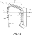
- FIGS. 1A and 1B illustrate perspective and side views, respectively, of one embodiment of a system 101 for implanting an intramedullary nail 109.
- the system 101 includes an insertion tool 103 that has a coupling portion 105 and a handle portion 107.
- the coupling portion 105 and the handle portion 107 can be separate parts that are removably joined together, while in other embodiments the coupling portion 105 and the handle portion 107 can be different regions of a single, integrally formed component.
- the coupling portion 105 releasably engages or couples to the proximal portion 111 of the nail 109.
- the free end of the coupling portion 105 can be provided with a snap-fit design to temporarily retain a portion of the intramedullary nail 109 prior to insertion of a fixation device 119 therethrough.
- a snap-fit design to temporarily retain a portion of the intramedullary nail 109 prior to insertion of a fixation device 119 therethrough.
- the handle portion 107 may include one or more openings 127, 129 configured to receive one or more guide wires 113, 115.
- the system 101 may include first and second guide wires 113, 115 as well as an optional guide sheath 117 through which the fixation device 119 may pass (e.g., the fixation device 119 can be inserted using the driver 121).
- the first and second guide wires 113, 115 may pass on opposing sides of both the nail 109 and the fixation device 119 (e.g. on posterior and anterior sides).
- the illustrated embodiment shows two guide wires, in other embodiments a single guide wire and corresponding guide wire hole may be used. In still other embodiments, three or more guide wires may be used. Additionally, the position and orientation of the guide wire holes can vary in different embodiments, for example being disposed more proximally or more distally along the insertion tool, etc.
- the insertion tool 103 allows the user to place one or more guide wires 113, 115.
- the guide wires 113, 155 are positioned both anterior and posterior to the nail 109.
- the guide wires 113, 115 may be positioned in this manner to prevent the distal fragments of the bone (e.g., distal fragments of the femoral head and neck) from rotating about the axis of the fixation device 119 when the fixation device 119 is advanced through the nail 109 and into the bone during the procedure.
- the handle portion 107 of the insertion tool 103 may include two guide wire receiving features such as holes 127, 129 on the opposing sides of the tool 103 that allow guide wires 113, 115 to pass through the respective holes.
- the guide wires 113, 115 are passed through the soft tissue and into the bone to help stabilize the insertion tool 103.
- the insertion tool 103 may not require any other instruments to guide the wires 113, 115 into the patient.
- the insertion tool 103 can achieve stability by resisting both rotational movement about the axis of the nail 109 as well as axial translation along the axis of the nail 109.
- FIGS. 2A-2C illustrate various views of the insertion tool 103 of the system 101 shown in FIGS. 1A and 1B .
- FIG. 2A is a partially exploded perspective view of the insertion tool 103 adjacent to the guide sheath 117
- FIG. 2B is a perspective view of the insertion tool 103 with the guide sheath 117 partially inserted therein
- FIG. 2C is an enlarged partial cross-sectional view of the engagement between the guide sheath 117 and the insertion tool 103.
- the guide sheath 117 can be removably inserted through a guide sheath receiving feature such as a hole 131 formed in the handle portion 107 of the insertion tool 103.
- the guide sheath hole 131 defines an axis that intersects with a first aperture 123 in the nail 109.
- the guide sheath 117 can be positioned through the guide sheath hole 131 such that it substantially aligns with the first aperture 123 in the nail 109, which is configured to receive fixation device 119 aimed at the calcar region of the bone.
- the guide sheath 117 can include a first retention member 133 on an outer surface of the guide sheath 117.
- the first retention member 133 can include, for example, ridged teeth, protrusions, or other such surface configured to engage with a corresponding second retention member 135 disposed within the guide sheath hole 131.
- the second retention member 135 can likewise include one or more ridges or protrusions. Together the first and second retention members 133, 135 form a retention mechanism 137 that allows the guide sheath 117 to be ratcheted towards the intramedullary nail 109 while restricting movement of the guide sheath 117 away from the intramedullary nail.
- the retention release mechanism 139 can disengage the second retention member 135 from the first retention member 133 when pressed by a user.
- the retention release mechanism 139 can be a button disposed on a lower surface 141 of the handle portion 107. Positioning this retention release mechanism 139 on the lower surface 141 of the insertion handle may prevent a user from accidentally releasing the guide sheath 117 while operating the device (e.g., while grasping the handle portion 107).
- FIGS. 3A-3F illustrate one method of steps of implanting an intramedullary nail into a fractured femur 143.
- a proximal end of the femur 143 can be accessed and the medullary cavity of the femur 143 can be reamed using a bone drill and reamer 145.
- the intramedullary nail 109 is coupled to the insertion tool 103 and the intramedullary nail 109 is disposed within the reamed cavity of the femur 143.
- FIG. 3A a proximal end of the femur 143 can be accessed and the medullary cavity of the femur 143 can be reamed using a bone drill and reamer 145.
- the intramedullary nail 109 is coupled to the insertion tool 103 and the intramedullary nail 109 is disposed within the reamed cavity of the femur 143.
- first and second guide wires 113 and 115 when used, one or more of the first and second guide wires 113 and 115 may be inserted through the soft tissue, for example, along parallel trajectories on opposing sides of the nail 109.
- the guide wires 113, 115 can limit or prevent inadvertent rotation of distal fragments of the femur 143 after the nail 109 is in position.
- the proximal fixation device 119 e.g., a lag screw or other suitable bone anchor
- the guide wires 113, 115 are retracted and in FIG.
- the distal fixation device 147 can additionally be inserted through the distal aperture 125 in the nail 109.
- the distal device 147 can be positioned using the guide sheath 117, which is positioned through another opening in the handle portion 107, such that the sheath 1117 is aligned with the distal opening 125 in the nail 109.
- the insertion tool 103 is disengaged from the nail 109, which is now secured in place via the proximal fixation device 119 and the distal fixation device 147.
- the nail 109 may extend along a portion of the length of femur 143. It is also contemplated, however, that the nail 109 may be of different sizes and shapes, for example, of longer lengths and/or different diameters to accommodate different anatomies and fractures.
- FIGS. 4A-4D illustrate another embodiment of an intramedullary nail 201, similar to intramedullary nail 109, with the addition of a cross-locking feature for proximal locking of the nail 201.
- Intramedullary nail 201 may include any of the features described above with respect to intramedullary nail 109.
- Intramedullary nail 201 may further include two interlocking proximal fixation devices 203, 205 (e.g., bone anchors, fasteners, or screws), for example, by providing converging and diverging purchase, along with bony fixation in the calcar of the femur 229, which is the strongest portion of the hip bone. Accordingly, the risk of failure due to cutout and/or rotation may be reduced.
- interlocking proximal fixation devices 203, 205 e.g., bone anchors, fasteners, or screws
- FIGS 4A-4D show side, side cross-sectional, and two perspective views, respectively, of the intramedullary nail 201 adjacent to a first fixation device 203.
- FIGS. 5A-5D illustrate side, side cross-sectional, and two perspective views, respectively, of the first, proximal fixation device 203 inserted through the intramedullary nail 201.
- FIGS. 6A-6D illustrate side, side cross-sectional, and two perspective views, respectively, of the system with a second, cross-locking fixation device 205 adjacent to the intramedullary nail 201 with the first fixation device 203 inserted therein.
- FIGS. 7A-7D illustrate side, side cross-sectional, and two perspective views, respectively, of the system with the second fixation device 205 inserted through both the intramedullary nail 201 and the first fixation device 203, thereby creating a cross-locking feature for proximal locking of the nail 201.
- the intramedullary nail 201 is configured to receive both the first and second fixation devices 203 and 205 therein.
- the intramedullary nail 201 includes an elongated body 207 having first and second apertures 209 and 211 formed therethrough in a proximal region 213, as well as a third aperture 215 formed in a distal region 217.
- the first aperture 209 can be sized and configured to receive the first fixation device 203 therethrough and the second aperture 211 can be sized and configured to receive the second fixation device 205 therethrough.
- the first fixation device 203 may be the same or similar to the proximal fixation device 119, described herein, and may include a bone screw or anchor configured for proximal locking of the nail 201.
- the first fixation device 203 may be a calcar screw or anchor configured to be aimed at a calcar region of the proximal humerus.
- the calcar screw 203 may have a threaded portion at its distal tip and a non-threaded portion along a substantial length of the screw 203.
- the calcar screw 203 may include traditional polyaxial or fixed angle calcar screws and anchors known in the art.
- the second fixation device 205 may also include a bone screw or anchor configured for proximal locking of the nail 201.
- This bone anchor or screw 205 may be substantially smaller in length and diameter relative to the calcar screw 203.
- the bone anchor or screw 205 is substantially sized and configured to be positioned through second opening 211 in the proximal end of the nail 201 and into a channel 219 in the first fixation device 203.
- the second device 205 is configured to interlock with the first fixation device 203, for example, enhanced purchase and bony fixation to the bone.
- the fixation device 205 may be configured to pass through a slot or channel 219 formed in the first fixation device 203. This interlocking feature of the first and second fixation devices 203, 205 can prevent cutout and rotation by providing converging and diverging purchase. In the case of a femur, this can also provide bony fixation in the calcar.
- the elongated slot 219 in the first fixation device 203 allows for controlled collapse, which leverages the natural compression between fragments from weight bearing or ligamentotaxis. Limited collapse is controlled by the length of the slot 219 to prevent the uncontrolled and excessive shortening of the femoral neck.
- the first fixation device 203 may include distal threads 221 and a proximal drive interface 223 configured to engage with a driver (not shown).
- the second fixation device 205 may have a narrower diameter than the first fixation device 203 such that the second fixation device 205 can pass through the slot 219 in the first fixation device 203.
- the second fixation device 205 may also include distal threads 225 and a proximal drive interface 227 configured to engage with a driver (not shown).
- the slot 219 can be disposed in the mid-shaft of the first fixation device 203 and may be sized and configured to allow the second fixation device 205 to pass therethrough.
- the slot 219 may be longer than necessary to allow translation of the first fixation device 203 after the second fixation device 205 is in place.
- the slot 219 may be strong enough to prevent rotation of the first fixation device 203 after the second fixation device 205 is in position.
- the slot 219 may have beveled proximal and distal edges to maximize material in the first fixation device 203 while allowing proximal and distal clearance of the second fixation device 205.
- the slot 219, in the first fixation device 203 may be symmetric to allow positioning of the second fixation device 205 in 180° increments, for example.
- a locking device 230 such as a set screw or washer, may be used to lock the first and/or the second fixation devices 203, 205 into position.
- the locking device 230 may be threaded through a hollow interior portion of the nail 201.
- the locking device 230 may have external threads, which are sized and configured to correspond to mating internal threads along the hollow interior portion of the nail 201.
- the interlocking fixation devices 203, 205 can be used selectively.
- the threaded locking device 230 may be threaded to engage the second fixation device 205; alternatively, the threaded locking device 230 may be threaded further down to lock the first fixation device 203, for example, if the second fixation device 205 is not used. This allows users the choice of a traditional or interlocking construct intraoperatively.
- An insertion tool 103 for implanting the system including the nail 201 and the interlocking first and second fixation devices 203 and 205 can be substantially similar to the system 101 described above with respect to FIGS. 1A-2C , except that an additional guide sheath hole may be formed in the handle portion 107 to accommodate a guide sheath along an appropriate trajectory to insert the second fixation device 205 through the second aperture 211 in the nail 201 and into engagement with the first fixation device 203.
- FIGS. 8A-8C illustrate one method of steps of implanting an intramedullary nail 201 with interlocking fixation devices 203, 205 into a fractured femur 229.
- the nail 201 has been inserted into a reamed medullary cavity of the femur 229 and the first fixation device 203 has been inserted through the first aperture 209 in the nail 201, similar to the technique described above with respect to FIGS. 3A-3D .
- a distal fixation device 231 can be inserted through the third aperture 215 in the nail 201, similar to the technique described above with respect to FIG. 3E .
- FIG. 8A-8C illustrate one method of steps of implanting an intramedullary nail 201 with interlocking fixation devices 203, 205 into a fractured femur 229.
- FIG. 8A the nail 201 has been inserted into a reamed medullary cavity of the femur 229 and the first fixation device 203 has been inserted through
- the second fixation device 205 is inserted through the second aperture 211 in the nail 201 and through the slot 219 in the first fixation device 203.
- these intersecting first and second fixation devices 203, 205 provide additional purchase in the head and neck region of the femur 229, and in particular the second fixation device 205 can provide bony fixation in the calcar. Accordingly, the interlocking first and second fixation devices 203, 205 can provide for improved stability and protection against common modes of intramedullary nail implant failure.
- FIGS. 9A-9N illustrate another example of an intramedullary nail 309, which may comprise a generally elongate body extending from a first, distal portion or end 310 to a second, proximal portion or end 311.
- the elongate body may be in the form of an elongate tubular rod configured to extend longitudinally within the intramedullary canal of a fractured bone.
- the elongate rod may be hollow or may be solid along its length.
- the elongate body may be substantially straight along a longitudinal axis of the nail 309 or may comprise one or more curves or bends to conform to the anatomical shape of the intramedullary canal.
- the nail 309 may be utilized in a piriformis fossa entry and the curvature may be provided in the AP (anteroposterior) direction. This curvature allows the nail 309 to be used either antegrade ( FIG. 9A ) or retrograde ( FIG. 9D ), as well as in the right leg or left leg.
- the nail 309' has curvature in the AP direction as well as a bend in the ML (medial-lateral) direction to facilitate entry at the tip of the greater trochanter.
- the nails 309 and 309' are the same unless otherwise described.
- the cross-section of the nail 309, taken at a right angle to a central longitudinal axis of the intramedullary nail 309 may be circular, oval, elliptical, or of any other suitable cross-dimensional shape.
- the radius of curvature of the nail 309 may change depending on the length of the nail 309 so that the curvature can match the anatomical curvature of the femur into which the nail 309 is being inserted. Often-times, in longer femurs (taller patients), the curvature has too small a radius, and surgeons struggle to insert the nail without causing bone damage.
- the method of radius planning based on displacement described herein reduces the likelihood of a problem by offering a more anatomically correct (larger) radius.
- the femur endpoints may be in a vertical line.
- the AP radius of curvature can be calculated using tangent circles if a valid starting point is assumed, for example, a nail length L of mm having a radius R.
- each tangent circle will have a radius R.
- Drawing a right triangle from the center C of the tangent circle, with R as the hypotenuse and 1 ⁇ 2 the nail length L as one leg of the triangle, the other leg will have a length z . Due to the curvature, the point where the legs 1/2L and z meet will be spaced a distance y from the tangent point T.
- R y /2 + L 2 /8 y .
- the constant y can be calculated.
- the radius R of curvature for each length L can be found.
- the distal end 310 of the nail 309 may include one or more distal openings 312-318 configured to receive one or more bone anchors, fasteners, or distal fixation devices 330, 332 that extend transversely through the distal end 310 of the intramedullary nail 309, and are thereby configured to secure the distal end 310 of the nail 309 within the canal.
- the distal fixation devices 330, 332 may include a bone screw or anchor configured for distal locking of the nail 309 and also reconstruction.
- the distal fixation device 330, 332 may include traditional polyaxial or fixed angle locking bone screws and anchors known in the art.
- the distal openings include an AP locking slot 312 and an AP locking opening 314.
- the openings also include a pair of ML locking openings 313, 315 and an ML locking slot 317.
- the AP and ML locking slots 312, 317 facilitate relative movement between the nail 309 and the locking screw 330 in the event compression or the like is applied during installation.
- the distal openings also include a pair of oblique openings 316, 318 configured to receive and guide reconstruction screws 332. As illustrated in FIG. 9J , each of the oblique openings 316, 318 is at an angle ⁇ 1 , ⁇ 2 relative to the axis of the nail 309.
- the angles ⁇ 1 , ⁇ 2 are in the range of 45° - 60°, and in the illustrated embodiment, are each 50°. It is preferred that the angles ⁇ 1 , ⁇ 2 are equal to one another such that the oblique openings 316, 318 are mirror images of one another, thereby allowing the nail 309 to be utilized in both right and left legs.
- the distal oblique openings 316, 318 all surgeons to lock distal screws at an angle or approach a distal fragment from a more proximal screw entry point. This configuration could be useful for treatment of periarticular fractures and condylar splits. Additionally, the oblique distal openings 316, 318 allow surgeons to access condylar fractures without risking soft tissue damage near the knee or hip joint upon entry.
- the proximal end 311 includes one or more proximal openings 123 configured to receive one or more bone anchors or fasteners 330, 332 that extend transversely through the proximal end 311 of the intramedullary nail 309, and are thereby configured to secure the proximal end 311 of the nail 309 within the canal and also reconstruction.
- the proximal fixation devices 330, 332 may include a bone screw or anchor.
- the fixation device 330 may be a locking screw and the fixation device 332 may be a calcar screw or anchor configured to be aimed at a calcar region of the proximal humerus, which may constitute the best quality bone in the region.
- the proximal openings may include a pair of ML openings 321, 323 and an ML slot 325.
- the ML openings 321, 323 and the ML slot 325 are configured to receive the locking screws 330.
- the ML locking slot 325 facilitates relative movement between the nail 309 and the locking screw 330 in the event compression or the like is applied during installation.
- the oblique angle ⁇ 1 may be about 100-150°, 110-140°, or about 120-135° relative to the nail 309 while the angle ⁇ 2 is about 30-80°, 40-70° or 45-60°.
- the proximal oblique openings 322, 324, 326 and 327 are also aligned so that they will function the same in either the right or left leg.
- the angles ⁇ 1 1 , ⁇ 3 are equal and the angles ⁇ 1 2 , ⁇ 4 are equal, however, such is not required.
- the openings whose axes are mirror images of one another are also offset in the AP plane from the sagittal plane, one by an ⁇ 1 in the anterior and the other by an angle ⁇ 2 in the anterior.
- the opening 322 is offset by ⁇ 1 while the opening 324 is offset ⁇ 2 .
- the opening 326 is offset by ⁇ 3 while the opening 327 is offset ⁇ 4 .
- the larger offset ⁇ 2 , ⁇ 4 is twice as large as the corresponding offset ⁇ 2 , ⁇ 4 . This creates room for the screw 330 to pass posteriorly to these two reconstruction screws 322 to make a fixed angle construct.
- the offset ⁇ 1 of opening 322 is equal to the offset ⁇ 4 of opening 327 while the offset ⁇ 2 of opening 324 is equal to the offset ⁇ 3 of opening 326.
- the nail 309 provides a hybrid antegrade/retrograde and left/right nail. Such a nail 309 is advantageous to hospitals and surgeons because it reduces stock and simplifies surgical planning.
- the bi-directional proximal oblique openings 322, 324, 326, 327 provide a variety of options for proximal femur fracture fixation, as well as a more stable construct. Additionally, the arrangement of the proximal openings 321-327 allows for a fixed-angle construct created by the screws 330, 332. The design further provides for three screws to be secured into the femoral neck. This fixed-angle construct provides more biomechanical stability than the traditional two screw configurations.
- the nail 309 of the present embodiment has an opening 334 at the proximal end 311.
- a shoulder 335 within the opening 334 defines a circumferential slot 336 on the inside diameter of the proximal portion 311 of the nail 309. This configuration takes up less space at the proximal end 311 of the nail 309 than a typical threaded connection, thereby freeing up space for more proximally located locking holes.
- the insertion tool 350 includes an expanding collet 370 and connecting bolt 354.
- An alignment tip 360 which connects within a through passage 353 in the aiming arm 352 of the insertion tool 350, is configured to align the bolt 354 with the expanding collet 370.
- the alignment tip 360 includes a hollow body 362 with a through passage 364 extending from a proximal end 361 to a distal end 363 of the body 362.
- the proximal end 361 of the body 362 is configured to be received into the through passage 353 of the aiming arm 362 with a press fit, however, other connecting mechanisms may be utilized.
- a shoulder 368 extends radially from the body 362 and engages the aiming arm 352 when fully inserted, as illustrated in FIGS. 11D and 11E .
- the distal end 363 of the body 362 has a recessed portion 366 configured to be received into the opening 334 in the proximal end of the nail 309.
- the expanding collet 370 includes a hollow body 372 with a through passage 374 extending from a proximal end 371 to a distal end 373 of the body 372.
- the distal end 373 has a radially outwardly extending collar 376, tabs, projections or the like.
- the collar 376 is configured to be received within the circumferential slot 336 in the proximal end 311 of the nail 309.
- Axial slots 375 extend from the distal end 373 of the body 372 and allow the distal end of the body 373 to compress radially inwardly, thereby allowing the collar 376 to pass through the alignment tip through passage 364 and the shoulder 335 within the proximal end 311 of the nail 309.
- An external shoulder 377 on the collet 370 contacts an internal shoulder 367 on the alignment tip 360 to limit the range of motion of the collet 370 relative to the alignment tip 360. Once the collar 376 is past the shoulder 335, the collar 376 is free to expand radially outwardly.
- the distal end 373 of the collet body 372 includes internal threads 378 configured for engagement with the threads 355 of the connecting bolt 354.
- the connecting bolt 354 then drives through the through passage 374 of the expandable collet 374 and engages the threads 378. As the connecting bolt 354 is threaded with the threads 378, it pushes the collar 376 outwardly to its major diameter and further drives the collar 376 into the circumferential slot 336 within the nail 309. In addition, when the bottom side of the head 356 of the bolt 354 makes contact with the top of the alignment tip 360, it allows for compression across the proximal nail 309, thus compressing any spacing in the connection.
- the assembly allows for quick, easy, and rigid connection of the nail 309 to the aiming arm 352. It is noted that any of the intramedullary nails described herein may include an internal circumferential slot and be connected to an insertion tool or the like utilizing an expanding collet as described.
- a self-retaining screw 400 and driver 430 assembly will be described. Screws are often affixed to drivers on the back table by a scrub tech or nurse and then they are handed to the surgeon who places the screw where it is needed. Between the back table, and the final seating of the screw into the bone, many actions can dislodge it from the driver, thus rendering it non-sterile, for example, when it hits the operating room floor. To minimize the likelihood of dislodging, the self-retaining nail locking screw 400 has features which achieve a more secure connection.
- the screw 400 includes a shaft 402 extending from a distal tip 404 to a proximal head 406.
- the shaft 402 includes a two thread 403, 405 start which provides for easier advancement.
- the head 406 defines a proximal torque bore 410 and a threaded bore 416 distally thereof.
- the torque bore 410 and the threaded bore 416 are in communication with one another and preferably coaxial.
- the torque bore 410 has a configuration with engaging surfaces to engage a complimentary torque tool.
- the torque bore 410 has a hexalobe configuration with a plurality of lobal recesses 412 extending radially from the central opening.
- the lobal recesses 412 define a maximum diameter D while the central opening defines a smaller diameter d.
- the lobal recesses 412 are configured to receive complementary lobes 436 on a driving tool head 430, as will be described in more detail below.
- the threaded bore 416 defines a plurality of internal threads 417 which are configured to be engaged by a threaded rod (not shown) which tightens into the threaded bore 416 at the bottom of the torque bore 410.
- the combination of a torque bore 410 and a threaded bore 416 allows for secure delivery of the screw 400 utilizing the threaded rod and thereafter additional tightening of the screw 400, if needed, utilizing a torque driver engaged with the torque bore 410.
- the torque driver head 430 illustrated therein has a taper in order to give it a stab and grab retaining feature on its own.
- the torque driver head 430 includes a proximal body 432 and a distal shaft 434 extending therefrom.
- the proximal body 432 and shaft 434 are preferably a unitary structure extending from a proximal end 431 to a distal end 433.
- a plurality of lobes 436 extend radially from the shaft 434 and have a complementary configuration to the lobal recesses 412 in the torque bore 410 of the screw 400.
- the lobes 436 taper, narrowing moving in the distal direction.
- the taper is generally constant over a first length E 1 and then more pronounced at the distal end 433 over the length E 2 .
- the lobes 436 define a larger maximum diameter F 1 in the proximate portion of the shaft 434 (see FIG. 12J ) and a smaller maximum diameter F 2 in the distal portion of the shaft 343 (see FIG. 12K ).
- the larger diameter F 1 is preferably larger than the maximum diameter D of the lobal recesses 412 and the smaller diameter F 2 is preferably smaller than the maximum diameter D of the lobal recesses 412, i.e. F 1 >D>F 2 .
- the distal end 433 of the torque driver head 430 moves easily into the torque bore 410, however, as the torque driver head 430 is inserted further, the lobes 436 engage the lobe recesses 412 in a friction fit, providing the stab and grab retaining feature. In some instances, this feature may provide sufficient secure connection without the need to utilize the threaded rod and threaded bore 416.
- FIGS. 13A-13F a headless version of the screw 400' will be described.
- a surgeon may desire to have as low of a head profile on a screw as possible.
- a fracture occurs near the joint space, it is often necessary for a surgeon to place screws through the articular surface.
- the locking screw used does not impinge any motion of the bones or soft tissues in that region.
- a headless screw may also be desired in areas where the soft tissue above the bone is very thin, so prominent screw heads may be felt or even seen by the patient post-op (e.g., in the proximal tibia).
- the headless screw 400' is similar to the screw of the previous embodiment and includes a shaft 402 extending from a distal tip 404 to a proximal head 406'.
- the shaft 402 includes a two thread 403, 405 start which provides for easier advancement.
- the screw 400' may have a single thread start or any other suitable configuration.
- the head 406' defines a proximal torque bore 410 and a threaded bore 416 distally thereof.
- the torque bore 410 has a configuration with engaging surfaces to engage a complimentary torque tool and the threaded bore 416 defines a plurality of internal threads 417.
- the head 406' of the present embodiment has a plurality of external threads 407.
- the threads 407 may have a four start thread that is half the pitch of the shaft thread.
- the threads 407 allow the head 406' to be sunk beneath the surface of the bone.
- the headless screw 400' provides a unique offering of a headless option that still acts the same as a standard locking screw.
- an intramedullary nail system includes an intramedullary nail in combination with at least one headless screw or fastener.
- the intramedullary nail may include intramedullary nails 109, 201, 309, 500 described herein or any other intramedullary nails generally known or hereinafter developed.
- the headless screw or fastener is intended to encompass a screw or fastener, which is blind such that the screw is fully threaded and has no head projecting past a major diameter of the screw thread and/or may encompass a screw or fastener having a head portion where the thread extends all the way to the head (e.g., a threaded head).
- the headless screw may include headless screw 400' described herein or any other headless screw generally known or hereinafter developed.
- the intramedullary nail 109, 201, 309, 500 is used in combination with at least one headless screw 400' or headless fastener.
- the headless screw 400' or other headless fastener may be positioned through the body of the nail 109, 201, 309, 500 such that the shaft 402 resides within one or more openings in the nail 109, 201, 309, 500.
- the shaft 402 of the headless screw 400' may be configured to mate with the intramedullary nail 109, 201, 309, 500 in a locking (e.g., threaded mating) or non-locking fashion.
- the threaded head 406' of the headless screw 400' may be positioned such that the head 406' is positioned at or near the outer surface of the bone, for example, as best seen in FIG. 9A .
- the intramedullary system may be substantially unnoticeable to a patient.
- traditional headed screws sometimes patients complain that they are able to feel the screw or the screw head protrudes from the surgical site causing irritation or pain to the patient. Accordingly, it may be suitable for one or more headless screws or fasteners to be used when securing the distal and/or proximal ends of the intramedullary nail, thereby resulting in superior patient outcomes.
- the nail 450 is provided with one or more threaded holes 454 along the elongate body 452 of the nail 450.
- the threaded hole 454 includes threads 453, 455 with a two start thread. In the illustrated embodiment, the threads 453, 455 provide a two start 60-degree machine thread. The threads 453, 455 will have the same pitch as the threads 403, 405 of the screw 400.
- the screw shaft 402 also has a two start thread for easy advancement.
- the threaded two start hole 454 in the nail 450 itself is an advantage over current interference holes because it is easy to manufacture, and requires no additional steps or special techniques on the part of the surgeon.
- a washer 470 configured to provide greater compression on the screw will be described.
- the screw and nail may not provide sufficient interference.
- surgeons often require a screw which interfaces with the nail itself.
- the near cortical wall is not stable, which is the case in a number of complex femur fractures, even an interference fit screw will not get any purchase in the near cortex, and therefore the fixation will be unstable.
- the washer 470 may be provided as an option for use with a screw and nail assembly if the conditions present the need for such.
- the washer 470 includes a hollow body 472 with a through passage 474 extending from a proximal end 471 of the body 472 to a distal end 473 of the body 472.
- the distal end 473 of the body 472 includes a plurality of cutouts 475 between distal tips 476. Each cutout 475 is approximately 90° such that each pair of opposed cutouts 475 is coaxial thereby allowing an outer diameter of the nail.
- the washer 470 fits over the major diameter of the screw and sits flush with the underside of the head. It may be inserted through a tissue protection sleeve along with the screw and driver.
- the screw continues to spin while the washer 470 grips the side of the nail. This allows the screw to get compression on the far side of the nail and hold the screw/washer construct firmly to the side of the nail. This provides a rigid fixation method when the cortical bone is not strong enough to do so.
- the washer 470 thereby expands the indications for which the nail can be used.
- FIGS. 16A-16D a first tibial intramedullary nail 500 will be described. It is recognized that the features of the nail 500 are not limited to use in a tibial nail and may be incorporated into other intramedullary nails.
- the intramedullary nail 500 generally comprises an elongate body 502 extending from a first, distal portion or end 203 to a second, proximal portion or end 501.
- the elongate body 502 may be in the form of an elongate tubular rod configured to extend longitudinally within the intramedullary canal of a fractured bone.
- the elongate rod may be hollow or may be solid along its length.
- the elongate body may be substantially straight along a longitudinal axis of the nail 500 or may comprise one or more curves or bends to conform to the anatomical shape of the intramedullary canal.
- the nail 500 is utilized in a tibia and the proximal end has a bend ⁇ relative to the shaft has a bend while the distal end has a bend ⁇ relative to the shaft.
- the bend ⁇ is approximately 10° while the distal end bend ⁇ is approximately 3°.
- the bends ⁇ and ⁇ are not limited to the described angles and may have larger or smaller bends depending on the anatomy of the bone.
- the distal end 503 of the tibial nail 500 contains four openings 510-513.
- the openings 510, 512 are oriented in the ML direction and the openings 511, 513 are oriented in the AP direction.
- the ML opening 510 and the AP opening 511 each include a 2 start thread 514 used to create a fixed angle construct with the locking screw, similar to that described above with respect to FIG. 14C .
- Fixed angle constructs are used to treat highly unstable fractures.
- the ML opening 510 is replaced with a combined oblique locking opening 520, with first and second openings 521, 522 each at an oblique angle, for example, at 30° off the sagittal plane.
- the combined oblique locking opening 520 allows the surgeon to insert locking screws 530 in two different orientations, thereby creating an alternative fixed angle construct.
- FIG. 16H another alternative distal end 503" of the nail 500" illustrates additional features which may be utilized to create a fixed angle construct.
- the AP opening 511' is defined as a broached hole while the AP opening 513' is defined as a threaded hole.
- the fixed angle construct is created by inserting a locking screw through the threaded or broached hole. The locking screw thread engages with the threads or broached features to stabilize the fracture by limiting the movement of the screw 530 relative to the nail 503".
- the proximal end 501 of the tibial nail 500 contains openings 515-518, including a pair of proximal oblique openings 515, an AP oblique opening 516, a proximal ML slot 517 and a proximal ML opening 517.
- the proximal oblique openings 515 are similar to those describe above with respect to the embodiment illustrated in FIG. 9A .
- the AP oblique opening 516 contains a 2 start thread 519 used to create a fixed angle construct with a locking screw.
- the proximal ML slot 517 is used for compression of fractures and static/dynamic locking modes.
- FIGS. 17A-17K illustrate various features of illustrative tibia nails 500, tools, systems and methods of inserting the tibia nails 500 will be described with reference to FIGS. 17A-17K .
- the tibial nail 500 is inserted into the medullary canal through an incision at the entry site.
- FIG. 17A illustrates an illustrative embodiment of a system 530 for implanting an intramedullary nail 500 utilizing the infra-patellar approach.
- the infra-patellar approach is the industry standard approach for insertion of the tibial nail 500. This approach is typically performed with the leg in the hyper-flexed (HF) position.
- the tibial nail 500 is inserted directly through the incision into the tibial canal.
- the system 530 includes an insertion tool 540 and an aiming guide 560.
- the insertion tool 540 includes a coupling portion 545 and a handle portion 547.
- the coupling portion 545 and the handle portion 547 can be separate parts that are removably joined together, while in other embodiments the coupling portion 545 and the handle portion 547 can be different regions of a single, integrally formed component.
- the handle portion 547 is preferably rigid, for example, made from stainless steel and also has provisions to attach an impaction shaft 546 and compression bolt 544.
- the coupling portion 545 has a connection portion 548 configured to releasably engage or couple to the proximal portion 501 of the nail 500.
- the connection portion 548 includes a threaded connector.
- other coupling mechanisms may be employed.
- the handle portion 547 includes a connection assembly 550 for releasably attaching the handle portion 547 to the aiming guide 560.
- the connection assembly 550 includes a body 551 with two bores 552, 554 defined therein.
- a connection button 553 extends into one of the bores 552.
- the connection button 553 is biased to a connected position as illustrated in FIG. 17B .
- the connection button 553 has an engagement portion 556 within the bore 552 configured to engage a slot 573 on a connection post 572 of the aiming guide, as will be described in more detail hereinafter.
- the engagement portion 556 includes a plate with a smaller diameter opening 557. To disengage the engagement portion 556, the button 553 is depressed such that the larger diameter opening 558 aligns with the connection post 572.
- other connection mechanisms may be employed.
- the tibial nail aiming guide 560 is used to install locking screws into the tibial nail 500.
- the aiming guide 560 sets the trajectory of the locking screws to interface with the proximal openings 515-518 of the nail 500.
- the aiming guide 560 is made from a radiolucent material.
- the aiming guide 560 includes an arcuate body 562 which extends between opposed end support blocks 564. Each end support block 564 defines a hole opening 563, which aligns with the ML opening 518, and a slot opening 565, which aligns with the ML slot 517.
- a plurality of intermediate support blocks 568A-C extending from the body 562.
- the support block 568A includes a hole opening 569 which is aligned with the AP oblique opening 516.
- the support blocks 568B and 568C each include a hole opening 569 which is aligned with a respective oblique opening 515.
- the openings 563, 565, and 569 are configured to support respective guide sheaths 580 similar to the guide sheaths 117 described above.
- the sheaths 580 are used to protect the soft tissue during the drilling process.
- the sheaths 580 accept drill sleeves and trocars of various sizes.
- the guide sheaths 580 and blocks 564, 568A-C may have retention members similar to those described above, with each block 564, 568A-C having a respective release mechanism 567.
- the aiming guide 560 also includes a connection assembly 570 configured to mate with the connection assembly 570 on the insertion handle 540.
- the connection assembly 570 includes a body 571 with a pair of connection posts 572, 574 extending therefrom which are configured to be received in the bores 552, 554 of the connection assembly 550.
- the connection post 572 includes a slot 573 configured to be selectively engaged by the engagement portion 556 of the connection button 553.
- the connector assembly 570 is a rigid structure and may be made from, for example, metal.
- the system 530 provides an insertion handle 547 with reliable and convenient connection assembly for attaching the aiming guide 560.
- a push button connection and release system allows tool free connection and disconnection of the aiming guide 560.
- the insertion handle 547 also contain an external compression bolt 544 used to apply pressure the locking screw in the dynamic position to compress a fracture gap.
- the aiming guide 560 utilizes a push button release mechanism 567 that locks the soft tissue sheaths 580 in place.
- the release mechanism 567 allows insertion of the soft tissue sheath 580 but prevents it from backing out. This feature helps to maintain the position of the soft tissue sheaths 580 for accurate screw length measurements and facilitates drilling and screw insertion.
- the aiming guide 560 is designed with extended sheath guides 580 for improved aiming accuracy.
- the supra-patellar approach uses a tibia entry point above the knee.
- a system 530' for use with the supra-patellar approach will be described with reference to FIGS. 17F-17L .
- the system 530' is substantially as in the previous embodiment but further includes a cannula assembly 590.
- the cannula assembly 590 protects the articular surface of the knee during the nail insertion process.
- the cannula assembly 590 also protects the articular surface of the knee during reaming.
- the reaming is performed through a drill guide 610 in the cannula 592 of the cannula assembly 590. Thereafter, the drill guide 610 is removed and nail 500 insertion is performed through the cannula 592 into the entry incision.
- the cannula assembly 590 includes a flexible cannula 592 and a rigid handle 596.
- the cannula 592 has a through passage 594 which is aligned with an opening 599 in the handle 596 to define a continuous passage.
- the flexible cannula 592 material is over-molded onto the rigid plastic handle 596.
- a pair of tibia guide slots 595 extend through the handle 596 and along the sides of the cannula 592.
- Transverse femur guide holes 597 extend through the handle 596. As shown in FIG. 17H , the guide slots 595 and guide holes 597 guide fixation pins 600, 602 into the tibia 144 or femur 143.
- the cannula assembly 590 is inserted through an incision in the skin and is the working portal through which the surgeon can perform reaming, drilling, and nail insertion.
- the guide slots 595 and holes 597 allow the surgeon to fix the cannula 592 in place during the procedure.
- the guide slots 595 and holes 597 allow the cannula to be fixed to the femur 143 or tibia 144 with converging pins 602, 600 depending on surgeon preference.
- the cannula 592 is reversible and can be used on either side of the patient. Referring to FIG. 17I , the cannula assembly 590 is designed to accept a metal drill sleeve 610 and round trocar 612.
- connection point 603 on the cannula handle 596 that accepts the connector 611 on the metal drill sleeve 610.
- the cannula 592 is tapered for easy removal of the drill sleeve 610.
- the soft, flexible cannula 592 is anatomically shaped to fit between the femoral condyles and minimize damage to the articular surface.
- the cannula assembly 590' in accordance with another illustrative embodiment will be described.
- the cannula assembly 590' is similar to the previous embodiment and includes a flexible cannula 592' extending from a rigid hub 596'.
- the rigid hub 596' includes legs 593 extending from each side of the cannula 592'.
- Each leg 593 of the hub 596' defines a respective tibia fixation hole 595' and a series of femur pin holes 597'.
- the two tibia fixation holes 595' are designed to accept k wire 600 for fixation to the tibia.
- the wires 600 can be convergent or parallel.
- the femur pin holes 597' are for femur fixation using half pins 602.
- the cannula assembly 590' is designed to accept a metal drill sleeve 610 and round trocar 612.
- the invention could be inter alia defined by the following aspects:
Landscapes
- Health & Medical Sciences (AREA)
- Orthopedic Medicine & Surgery (AREA)
- Life Sciences & Earth Sciences (AREA)
- Surgery (AREA)
- Medical Informatics (AREA)
- General Health & Medical Sciences (AREA)
- Biomedical Technology (AREA)
- Heart & Thoracic Surgery (AREA)
- Nuclear Medicine, Radiotherapy & Molecular Imaging (AREA)
- Molecular Biology (AREA)
- Animal Behavior & Ethology (AREA)
- Engineering & Computer Science (AREA)
- Public Health (AREA)
- Veterinary Medicine (AREA)
- Neurology (AREA)
- Dentistry (AREA)
- Oral & Maxillofacial Surgery (AREA)
- Surgical Instruments (AREA)
Abstract
Description
- This application is a continuation-in-part of
U.S. Appln. Serial No. 15/272,850, filed on September 22, 2016 - The present technology is generally related to intramedullary nail implantation for treatment of bone fractures. In particular, several embodiments are directed to systems and methods for implanting an intramedullary nail for immobilizing bone fractures.
- The significant long bones of the extremities are the humerus, radius and ulna of the upper extremity and the femur and tibia of the lower extremity. Following an injury to the long bone, and in particular, injuries resulting in one or more fractures of the long bone, one or more fixation devices may be used to immobilize the fracture fragments and stabilize the long bone. Bone fractures can be treated with screws or other fixation devices inserted into or through the bone to stabilize it once the fractured portions have been brought into proper alignment. Femoral neck fixation, for example, can be used to treat hip fractures by inserting an intramedullary nail into the medullary cavity of the fractured femur followed by insertion of a fixation screw into the femoral neck/head at an angle relative to the intramedullary nail. Similarly, other long bone fractures can be treated by inserting an intramedullary nail into the intramedullary canal of the bone and providing the appropriate proximal and/or distal fixation. Traditional intramedullary devices may suffer from a number of disadvantages, however. For example, they may be susceptible to implant failure and difficulty in alignment of the fixation screw with respect to the intramedullary nail. Accordingly, there is a need for improved systems and methods for intramedullary nail implantation.
- Intramedullary nails, systems, insertion tools, and method of treatment are provided. The intramedullary nails may be suitable for implanting within a medullary canal of a fractured long bone and subsequently providing proximal fixation and/or distal fixation, for example, with one or more anchors, fasteners, fixation screws, or the like. Suitable long bones may include the humerus, radius, ulna, femur, tibia, or the like. Although generally described with reference to the femur and tibia, it will be appreciated that the intramedullary nail and system may be adapted for use with any long bone.
- According to one aspect, an intramedullary nail is provided. The intramedullary nail may comprise a generally elongate body extending from a first, distal end to a second, proximal end. The distal end may include one or more openings configured to receive one or more bone anchors or fasteners that extend transversely through the distal end intramedullary nail, and thereby configured to secure the distal end of the nail. The proximal end may also include one or more openings configured to receive one or more bone anchors or fasteners that extend transversely through the proximal end of the intramedullary nail, and thereby configured to secure the proximal end of the nail.
- In one aspect, a system for inserting an intramedullary nail into a bone is provided. The system includes an intramedullary nail with an opening or aperture formed therein. An insertion tool can temporarily engage with an end of the intramedullary nail during implantation, and release from the nail once the procedure is complete. A receiving feature for a guide sheath (e.g., a hole, recess, etc.) is disposed in the handle portion and can receive a guide sheath therethrough. The receiving feature defines an axis such that, when the intramedullary nail is coupled to the coupling portion, a guide sheath inserted through the receiving feature substantially aligns with the aperture in the intramedullary nail. A first retention member is disposed in the insertion tool adjacent to the guide sheath receiving feature. The first retention member can interact with a second retention member on the guide sheath to form a ratchet-like mechanism that restrict movement of the guide sheath with respect to the receiving feature. A retention release mechanism can be located on a lower portion (e.g., a bottom surface) of the insertion tool. A guide wire receptacle (e.g., a hole, recess, etc.) can receives a guide wire therethrough and is positioned such that, when the intramedullary nail is coupled to the coupling portion, a guide wire inserted through the receiving feature runs along an axis adjacent to the side surface of the intramedullary nail.
- In another aspect, a method for inserting an intramedullary nail into a patient is provided. The method includes inserting a nail into a medullary canal of a patient along a first axis. For insertion, the nail is coupled at its proximal end to an insertion tool. A guide wire is inserted through a guide wire hole in the insertion tool along a second axis such that the guide wire runs nearby or adjacent to a side surface of the nail. A screw or other bone fixation device is inserted through a receptacle (e.g., a hole, recess, or other suitable structure) formed in the insertion tool such that the screw passes through an aperture formed in the nail.
- In accordance with another aspect, an implant is provided. The implant includes an intramedullary nail that is elongated along a first axis. First and second openings or apertures are disposed in a proximal portion of the nail. The first aperture defines a second axis transverse to the first axis, and the second aperture defines a third axis transverse to the first axis. The third axis intersects with the second axis at a point spaced apart from the nail. In some embodiments, the first screw can be inserted through the first aperture along the second axis and a second screw can be inserted through the second aperture along the third axis. The second screw can be at least partially inserted through a slot in the first screw such that the two screws interlock. The second screw can be shorter than the first screw but long enough that at least a threaded distal tip extends beyond the slot in the first screw to provide some purchase in the bone.
- In accordance with another aspect, an implant is provided. The implant includes an intramedullary nail having a body elongated along a first axis. The body has a proximal portion and a distal portion. A first aperture is formed in the proximal portion and defines a second axis transverse to the first axis at a first angle. A second aperture is formed in the proximal portion and defines a third axis transverse to the first axis at a second angle. The third axis intersects with the second axis at the first axis and the first and second angles are complementary angles.
- In accordance with another aspect, an intramedullary system configured to stabilize bone is provided. The system comprises an intramedullary nail and one or more headless fasteners or screws. The headless fastener extends from a first end to a second end. The headless fastener has a shaft configured to be positioned through the first aperture or the second aperture in the intramedullary nail and the first end (e.g., in some instances a threaded head) of the headless fastener is configured to be positioned against or within the bone. Unlike traditional headed screws which sometimes cause pain or irritation to patients, one or more headless screws or fasteners can be used when securing the distal and/or proximal ends of the intramedullary nail, thereby resulting in a system with superior patient outcomes.
- In accordance with another aspect, a system for inserting an intramedullary nail into a bone is provided. The system includes an intramedullary nail having a proximal end, a distal end, at least one side surface extending between the proximal end and the distal end, and an aperture through the intramedullary nail. An insertion tool includes a handle portion, a coupling portion and an aiming guide. The handle portion defines a first connection assembly. The coupling portion extends from the handle portion and is configured to removably couple to the proximal end of the intramedullary nail. The aiming guide has a body with at least one support block and a second connection assembly. The first and second connection assemblies are configured to releasably interconnect the handle portion and the aiming guide. The at least one guide block defines a guide sheath hole configured to receive a guide sheath therethrough. The guide sheath hole is positioned such that, when the intramedullary nail is coupled to the coupling portion, the guide sheath hole substantially aligns with the aperture in the intramedullary nail.
- In accordance with another aspect, a connection assembly for interconnecting an intramedullary nail and insertion tool is provided. The intramedullary nail extends between a proximal end and a distal end and has a circumferential slot defined within the proximal end. The insertion tool includes an aiming arm with a hole defined therein. The connection assembly includes an alignment tip having a hollow body extending from a proximal end to a distal end with the proximal end configured to be securely connected within the hole of the aiming arm. An expanding collet has a hollow body extending from a collet proximal end to a collet distal end. The collet distal end has a radially outwardly extending collar and internal threads. The collet body defines axial slots extending from the distal end of the body which allow the distal end of the body to compress radially inwardly, thereby allowing the collar to pass through the alignment tip through passage and into the circumferential slot of the intramedullary nail. A connecting bolt has a threaded shaft and extends through the hole in the aiming arm and into threaded engagement with the internal threads of the expanding collet such that the collar is pushed outwardly to its major diameter.
- Also provided are kits including intramedullary nails of varying shapes and sizes, bone anchors, fasteners, insertion tools, and components for installing the same.
- According to a further aspect of the invention, it is provided a system for inserting an intramedullary nail into a bone, the system comprising: an intramedullary nail having a proximal end, a distal end, at least one side surface extending between the proximal end and the distal end, and an aperture through the intramedullary nail; and an insertion tool comprising: a handle portion, the handle portion defining a first connection assembly; a coupling portion extending from the handle portion, the coupling portion configured to removably couple to the proximal end of the intramedullary nail; an aiming guide having a body with at least one support block and a second connection assembly, wherein the first and second connection assemblies are configured to releasably interconnect the handle portion and the aiming guide; and wherein the at least one guide block defines a guide sheath hole configured to receive a guide sheath therethrough, the guide sheath hole positioned such that, when the intramedullary nail is coupled to the coupling portion, the guide sheath hole substantially aligns with the aperture in the intramedullary nail, wherein the rigid handle, alone or in conjunction with flexible cannula, defines a pair of tibia pin guides, and the rigid handle further defines at least two femur pin guides and wherein the cannula assembly further comprises: a drill sleeve and a trocar configured to extend through the flexible cannula through passage.
- According to another aspect of the invention, it is provided a connection assembly for interconnecting an intramedullary nail and insertion tool, the intramedullary nail extending between a proximal end and a distal end and having a circumferential slot defined within the proximal end, and the insertion tool including an aiming arm with a hole defined therein, the connection assembly comprising: an alignment tip having a hollow body extending from a proximal end to a distal end, the proximal end configured to be securely connected within the hole of the aiming arm; an expanding collet having a hollow body extending from a collet proximal end to a collet distal end, the collet distal end having a radially outwardly extending collar and internal threads, the collet body defining axial slots extending from the distal end of the body which allow the distal end of the body to compress radially inwardly, thereby allowing the collar to pass through the alignment tip through passage and into the circumferential slot of the intramedullary nail; and a connecting bolt having a threaded shaft, the connecting bolt extending through the hole in the aiming arm and into threaded engagement with the internal threads of the expanding collet such that the collar is push outwardly to its major diameter.
- In a version the proximal end of the tip hollow body is configured to be received into the hole of the aiming arm with a press fit.
- In another version, the distal end of the tip hollow body has a recessed portion configured to be received into an opening in the proximal end of the intramedullary nail.
- In still another version, the connection bolt includes a head which makes contact with the proximal end of the alignment tip hollow body and causes compression across the intramedullary nail
- A more complete understanding of the present invention, and the attendant advantages and features thereof, will be more readily understood by reference to the following detailed description when considered in conjunction with the accompanying drawings wherein:
-
FIGS. 1A and1B illustrate a system for implanting an intramedullary nail. -
FIGS. 2A-2C illustrate various views of an insertion handle of the system shown inFIGS. 1A and1B . -
FIGS. 3A-3F illustrate steps of implanting an intramedullary nail into a fractured femur. -
FIGS. 4A-4D illustrate various views of an intramedullary nail and a first fixation device. -
FIGS. 5A-5D illustrate various views of the first fixation device inserted through the intramedullary nail. -
FIGS. 6A-6D illustrate various views of a second fixation device and the intramedullary nail with the first fixation device inserted therein. -
FIGS. 7A-7D illustrate various views of the second anchor inserted through the intramedullary nail and the first fixation device. -
FIGS. 8A-8C illustrate steps of implanting an intramedullary nail with interlocking fixation devices into a fractured femur. -
FIGS. 9A-9N illustrate various views of an illustrative intramedullary nail. -
FIGS. 10A-10C illustrate steps of a method of calculating the radius of curvature of a femoral nail. -
FIGS. 11A-11E illustrate various views of an insertion tool and intramedullary nail connection assembly. -
FIGS. 12A-12K illustrate various views of a locking screw and corresponding torque driver head. -
FIGS. 13A-13F illustrate various views of a headless locking screw. -
FIGS. 14A-14C illustrate various views of a nail including a locking screw opening with a 2 start thread configuration. -
FIGS. 15A-15C illustrate various views of a screw compression washer. -
FIGS. 16A-16H illustrate various views of illustrative tibial nails. -
FIGS. 17A-17L illustrate various views of illustrative insertion systems. - Intramedullary nails, systems, insertion tools, and method of treatment are provided. The intramedullary nails may be suitable for implantation within the intramedullary canal of a fractured long bone and subsequently providing proximal fixation and/or distal fixation, for example, with one or more anchors, fasteners, fixation screws, or the like. Suitable long bones may include the humerus, radius, ulna, femur, tibia, or the like. Although further described with reference to hip fractures of the femur or fractures of the tibia, it will be appreciated that the intramedullary nail and system may be adapted for use with any long bone.
- In conventional hip fracture fixation techniques, there are four main failure modes: axial cutout, cephalad cutout, proximal fragment rotation, and nonunion. "Cutout" is the term for hip screw subsidence into the articular surface of the hip. Cutout can occur in either a cephalad (toward the head) or axial direction (along the axis of the hip screw). Axial cutout is the result of an implant with a small axial profile that provides little resistance to axial translation. Axial cutout can be addressed by the "controlled collapse" features on certain modern hip fracture nails; the hip screw is allowed to translate through the nail, even after the set screw is locked in place. Cephalad cutout is the radial translation of the nail which is the result of a narrow implant that "windshield wipers" through the weak cancellous bone in the hip. Proximal fragment rotation is the result of a circular profile hip screw that acts as a fulcrum to the proximal hip fragment. Fracture nonunion is the result of biologic or mechanical factors that are incompatible with the bone healing process. Biologic factors of the patient are not controllable by the implant. Mechanical factors are those that typically allow fixation that is too rigid or too flexible. Nonunion is usually the precursor to one of the other three failure modes. Occasionally, nonunion will cause the nail to break in fatigue before the bone fails.
- The intramedullary nails and systems described herein may address one or more of these failure modes. In some embodiment, the intramedullary nail includes proximal and distal locking, for example, to prevent cutout. In other embodiments, the intramedullary nail may include proximal locking including two interlocking fixation devices (e.g., screws), for example, by providing converging and diverging purchase, along with bony fixation in the calcar of the femur, which is the strongest portion of the hip bone. Accordingly, the risk of failure due to cutout and/or rotation can be reduced.
- Additionally, some intramedullary nail implantation systems fail to adequately address the problems of fragment rotation during implantation. Rotation occurs when fragments of the bone rotate about the axis of the screw during the implantation procedure. Conventional anti-rotation technologies require the use of additional instruments or are limited to a single wire placement. In some embodiments, an insertion tool is directly coupled to the intramedullary nail and additional instruments are not needed for the placement of an anti-rotation guide wire and allow the user to place one or more guide wires anterior and/or posterior to the nail. These guide wires can be positioned to prevent the distal fragments of the femoral head and neck from rotating about the axis of the anchor during the procedure.
- Some systems may be susceptible to backout during the implantation procedure. Backout occurs when the guide sheath used to insert the screw through the intramedullary nail moves proximally away from the bone. Conventional systems either have no features to prevent backout or else provide backout prevention measures that obstruct the normal positioning of the hands during the procedure, resulting in the risk of releasing the guide sheaths and dropping them to the floor. Ratchets on the insertion tool may have the release button facing towards the grip portion on the insertion tool and may present the danger of the user's hand slipping and inadvertently pressing the button. Accidentally pressing the button could result in releasing the sheath and causing the sheath to fall on the floor. In some embodiments, a backout prevention system (e.g., a ratchet system) may be disposed on the lower end of the insertion tool, which allows a user to have a hand placed on the grip of the insertion tool without the risk of inadvertently pressing the ratchet release button.
- Further specific details of several embodiments of the present technology are described below with reference to
FIGS. 1A-8C . Although many of the embodiments are described below with respect to devices, systems, and methods for implantation of intramedullary nails, other embodiments are within the scope of the present technology. Additionally, other embodiments of the present technology can have different configurations, components, and/or procedures than those described herein. For example, other embodiments can include additional elements and features beyond those described herein, or other embodiments may not include several of the elements and features shown and described herein. - For ease of reference, throughout this disclosure identical reference numbers are used to identify similar or analogous components or features, but the use of the same reference number does not imply that the parts should be construed to be identical. Indeed, in many examples described herein, the identically numbered parts are distinct in structure and/or function.
-
FIGS. 1A and3F illustrate one example of anintramedullary nail 109, which may comprise a generally elongate body extending from a first, distal portion or end 110 to a second, proximal portion or end 111. The elongate body may be in the form of an elongate tubular rod configured to extend longitudinally within the intramedullary canal of a fractured bone. The elongate rod may be hollow or may be solid along its length. The elongate body may be substantially straight along a longitudinal axis of thenail 109 or may comprise one or more curves or bends to conform to the anatomical shape of the intramedullary canal. The cross-section of thenail 109, taken at a right angle to a central longitudinal axis of theintramedullary nail 109, may be circular, oval, elliptical, or of any other suitable cross-dimensional shape. Theproximal portion 111 may have an enlarged diameter or head portion relative to thedistal portion 110 of thenail 109. Theenlarged head portion 111 may be sized and configured to be received in the greater trochanter region of the femur. Theintramedullary nail 109 may be configured to be positioned in the proximal end of the femur for cephalomedullary fixation. It is envisioned, however, that theintramedullary nail 109 may be configured to be positioned through other approaches and locations (e.g., distal end) depending on the bone (e.g., femur, tibia) and type of fracture. - The
distal end 110 may include one ormore openings 125 configured to receive one or more bone anchors, fasteners, ordistal fixation devices 147 that extend transversely through thedistal end 110 of theintramedullary nail 109, and are thereby configured to secure thedistal end 110 of thenail 109 within the canal. Thedistal fixation devices 147 may include a bone screw or anchor configured for distal locking of thenail 109. Thedistal fixation device 147 may include traditional polyaxial or fixed angle locking bone screws and anchors known in the art. - The
proximal end 111 may also include one ormore openings 123 configured to receive one or more bone anchors orfasteners 119 that extend transversely through theproximal end 111 of theintramedullary nail 109, and are thereby configured to secure theproximal end 111 of thenail 109 within the canal. Theproximal fixation devices 119 may include a bone screw or anchor configured for proximal locking of thenail 109. Thefixation device 119 may be a calcar screw or anchor configured to be aimed at a calcar region of the proximal humerus, which may constitute the best quality bone in the region. Theopening 123 andanchor 119 may be angled about 100-150°, 110-140°, or about 120-135° relative to thenail 109 to engage the calcar region of the bone. Thecalcar screw 119 may have an enlarged diameter relative to thedistal screw 147. Theproximal fixation device 119 may include traditional polyaxial or fixed angle calcar screws and anchors known in the art. Theproximal end 111 may also includeadditional openings 123, for example, for one or more cross-locking devices (e.g.,device 205 described in more detail below). - The
intramedullary nail 109 and anchors 119, 147 may be comprised of any suitable biocompatible materials. Theintramedullary nail 109 and anchors 119, 147 may be comprised of titanium, cobalt chrome, cobalt-chrome-molybdenum, stainless steel, tungsten carbide, carbon composite, plastic or polymer-such as polyetheretherketone (PEEK), polyethylene, ultra high molecular weight polyethylene (UHMWPE), resorbable polylactic acid (PLA), polyglycolic acid (PGA), combinations or alloys of such materials, or other appropriate biocompatible materials that have sufficient strength to secure and hold bone, while also having sufficient biocompatibility to be implanted into a body. -
FIGS. 1A and1B illustrate perspective and side views, respectively, of one embodiment of asystem 101 for implanting anintramedullary nail 109. Thesystem 101 includes aninsertion tool 103 that has acoupling portion 105 and ahandle portion 107. In some embodiments, thecoupling portion 105 and thehandle portion 107 can be separate parts that are removably joined together, while in other embodiments thecoupling portion 105 and thehandle portion 107 can be different regions of a single, integrally formed component. Thecoupling portion 105 releasably engages or couples to theproximal portion 111 of thenail 109. For example, the free end of thecoupling portion 105 can be provided with a snap-fit design to temporarily retain a portion of theintramedullary nail 109 prior to insertion of afixation device 119 therethrough. However, those skilled in the art will understand that other coupling mechanisms may be employed. - The
handle portion 107 may include one ormore openings more guide wires system 101 may include first andsecond guide wires optional guide sheath 117 through which thefixation device 119 may pass (e.g., thefixation device 119 can be inserted using the driver 121). As illustrated, the first andsecond guide wires nail 109 and the fixation device 119 (e.g. on posterior and anterior sides). Although the illustrated embodiment shows two guide wires, in other embodiments a single guide wire and corresponding guide wire hole may be used. In still other embodiments, three or more guide wires may be used. Additionally, the position and orientation of the guide wire holes can vary in different embodiments, for example being disposed more proximally or more distally along the insertion tool, etc. - As illustrated, the
insertion tool 103 allows the user to place one ormore guide wires guide wires 113, 155 are positioned both anterior and posterior to thenail 109. Theguide wires fixation device 119 when thefixation device 119 is advanced through thenail 109 and into the bone during the procedure. Thehandle portion 107 of theinsertion tool 103 may include two guide wire receiving features such asholes tool 103 that allowguide wires guide wires insertion tool 103. In this configuration, theinsertion tool 103 may not require any other instruments to guide thewires insertion tool 103 can achieve stability by resisting both rotational movement about the axis of thenail 109 as well as axial translation along the axis of thenail 109. -
FIGS. 2A-2C illustrate various views of theinsertion tool 103 of thesystem 101 shown inFIGS. 1A and1B . In particular,FIG. 2A is a partially exploded perspective view of theinsertion tool 103 adjacent to theguide sheath 117,FIG. 2B is a perspective view of theinsertion tool 103 with theguide sheath 117 partially inserted therein, andFIG. 2C is an enlarged partial cross-sectional view of the engagement between theguide sheath 117 and theinsertion tool 103. - The
guide sheath 117 can be removably inserted through a guide sheath receiving feature such as ahole 131 formed in thehandle portion 107 of theinsertion tool 103. Theguide sheath hole 131 defines an axis that intersects with afirst aperture 123 in thenail 109. Theguide sheath 117 can be positioned through theguide sheath hole 131 such that it substantially aligns with thefirst aperture 123 in thenail 109, which is configured to receivefixation device 119 aimed at the calcar region of the bone. Theguide sheath 117 can include afirst retention member 133 on an outer surface of theguide sheath 117. Thefirst retention member 133 can include, for example, ridged teeth, protrusions, or other such surface configured to engage with a correspondingsecond retention member 135 disposed within theguide sheath hole 131. Thesecond retention member 135 can likewise include one or more ridges or protrusions. Together the first andsecond retention members retention mechanism 137 that allows theguide sheath 117 to be ratcheted towards theintramedullary nail 109 while restricting movement of theguide sheath 117 away from the intramedullary nail. Theretention release mechanism 139 can disengage thesecond retention member 135 from thefirst retention member 133 when pressed by a user. For example, theretention release mechanism 139 can be a button disposed on alower surface 141 of thehandle portion 107. Positioning thisretention release mechanism 139 on thelower surface 141 of the insertion handle may prevent a user from accidentally releasing theguide sheath 117 while operating the device (e.g., while grasping the handle portion 107). -
FIGS. 3A-3F illustrate one method of steps of implanting an intramedullary nail into a fracturedfemur 143. Referring first toFIG. 3A , a proximal end of thefemur 143 can be accessed and the medullary cavity of thefemur 143 can be reamed using a bone drill andreamer 145. Next, as shown inFIG. 3B , theintramedullary nail 109 is coupled to theinsertion tool 103 and theintramedullary nail 109 is disposed within the reamed cavity of thefemur 143. InFIG. 3C , when used, one or more of the first andsecond guide wires nail 109. Theguide wires femur 143 after thenail 109 is in position. The proximal fixation device 119 (e.g., a lag screw or other suitable bone anchor) is also passed through thefirst aperture 123 in thenail 109 and into the head/neck region of thefemur 143. InFIG. 3D , theguide wires FIG. 3E , thedistal fixation device 147 can additionally be inserted through thedistal aperture 125 in thenail 109. Thedistal device 147 can be positioned using theguide sheath 117, which is positioned through another opening in thehandle portion 107, such that the sheath 1117 is aligned with thedistal opening 125 in thenail 109. InFIG. 3F , theinsertion tool 103 is disengaged from thenail 109, which is now secured in place via theproximal fixation device 119 and thedistal fixation device 147. As shown, thenail 109 may extend along a portion of the length offemur 143. It is also contemplated, however, that thenail 109 may be of different sizes and shapes, for example, of longer lengths and/or different diameters to accommodate different anatomies and fractures. -
FIGS. 4A-4D illustrate another embodiment of anintramedullary nail 201, similar tointramedullary nail 109, with the addition of a cross-locking feature for proximal locking of thenail 201.Intramedullary nail 201 may include any of the features described above with respect tointramedullary nail 109.Intramedullary nail 201 may further include two interlockingproximal fixation devices 203, 205 (e.g., bone anchors, fasteners, or screws), for example, by providing converging and diverging purchase, along with bony fixation in the calcar of thefemur 229, which is the strongest portion of the hip bone. Accordingly, the risk of failure due to cutout and/or rotation may be reduced. -
FIGS 4A-4D show side, side cross-sectional, and two perspective views, respectively, of theintramedullary nail 201 adjacent to afirst fixation device 203.FIGS. 5A-5D illustrate side, side cross-sectional, and two perspective views, respectively, of the first,proximal fixation device 203 inserted through theintramedullary nail 201.FIGS. 6A-6D illustrate side, side cross-sectional, and two perspective views, respectively, of the system with a second,cross-locking fixation device 205 adjacent to theintramedullary nail 201 with thefirst fixation device 203 inserted therein.FIGS. 7A-7D illustrate side, side cross-sectional, and two perspective views, respectively, of the system with thesecond fixation device 205 inserted through both theintramedullary nail 201 and thefirst fixation device 203, thereby creating a cross-locking feature for proximal locking of thenail 201. - Referring to
FIGS. 4A-8C together, theintramedullary nail 201 is configured to receive both the first andsecond fixation devices intramedullary nail 201 includes anelongated body 207 having first andsecond apertures proximal region 213, as well as athird aperture 215 formed in adistal region 217. Thefirst aperture 209 can be sized and configured to receive thefirst fixation device 203 therethrough and thesecond aperture 211 can be sized and configured to receive thesecond fixation device 205 therethrough. - The
first fixation device 203, may be the same or similar to theproximal fixation device 119, described herein, and may include a bone screw or anchor configured for proximal locking of thenail 201. For example, thefirst fixation device 203 may be a calcar screw or anchor configured to be aimed at a calcar region of the proximal humerus. Thecalcar screw 203 may have a threaded portion at its distal tip and a non-threaded portion along a substantial length of thescrew 203. Thecalcar screw 203 may include traditional polyaxial or fixed angle calcar screws and anchors known in the art. - The
second fixation device 205 may also include a bone screw or anchor configured for proximal locking of thenail 201. This bone anchor or screw 205 may be substantially smaller in length and diameter relative to thecalcar screw 203. The bone anchor or screw 205 is substantially sized and configured to be positioned throughsecond opening 211 in the proximal end of thenail 201 and into achannel 219 in thefirst fixation device 203. Thus, thesecond device 205 is configured to interlock with thefirst fixation device 203, for example, enhanced purchase and bony fixation to the bone. Although shown with thesecond fixation device 205 positioned above thefirst fixation device 203 and angled downwardly into contact with thefirst fixation device 203, it is also envisioned that these relative positons may be reversed or thefixation devices devices second fixation device 205 may be configured to pass through a slot orchannel 219 formed in thefirst fixation device 203. This interlocking feature of the first andsecond fixation devices elongated slot 219 in thefirst fixation device 203 allows for controlled collapse, which leverages the natural compression between fragments from weight bearing or ligamentotaxis. Limited collapse is controlled by the length of theslot 219 to prevent the uncontrolled and excessive shortening of the femoral neck. Thefirst fixation device 203 may includedistal threads 221 and aproximal drive interface 223 configured to engage with a driver (not shown). Thesecond fixation device 205 may have a narrower diameter than thefirst fixation device 203 such that thesecond fixation device 205 can pass through theslot 219 in thefirst fixation device 203. Thesecond fixation device 205 may also includedistal threads 225 and aproximal drive interface 227 configured to engage with a driver (not shown). - The
slot 219 can be disposed in the mid-shaft of thefirst fixation device 203 and may be sized and configured to allow thesecond fixation device 205 to pass therethrough. Theslot 219 may be longer than necessary to allow translation of thefirst fixation device 203 after thesecond fixation device 205 is in place. Theslot 219 may be strong enough to prevent rotation of thefirst fixation device 203 after thesecond fixation device 205 is in position. Theslot 219 may have beveled proximal and distal edges to maximize material in thefirst fixation device 203 while allowing proximal and distal clearance of thesecond fixation device 205. Theslot 219, in thefirst fixation device 203, may be symmetric to allow positioning of thesecond fixation device 205 in 180° increments, for example. - In at least one embodiment, a
locking device 230, such as a set screw or washer, may be used to lock the first and/or thesecond fixation devices FIG. 7B , thelocking device 230 may be threaded through a hollow interior portion of thenail 201. Thelocking device 230 may have external threads, which are sized and configured to correspond to mating internal threads along the hollow interior portion of thenail 201. As thelocking device 230 is threaded downwardly and comes into contact with the first orsecond fixation devices respective fixation device nail 201. In some embodiments, the interlockingfixation devices locking device 230 may be threaded to engage thesecond fixation device 205; alternatively, the threadedlocking device 230 may be threaded further down to lock thefirst fixation device 203, for example, if thesecond fixation device 205 is not used. This allows users the choice of a traditional or interlocking construct intraoperatively. - An
insertion tool 103 for implanting the system including thenail 201 and the interlocking first andsecond fixation devices system 101 described above with respect toFIGS. 1A-2C , except that an additional guide sheath hole may be formed in thehandle portion 107 to accommodate a guide sheath along an appropriate trajectory to insert thesecond fixation device 205 through thesecond aperture 211 in thenail 201 and into engagement with thefirst fixation device 203. -
FIGS. 8A-8C illustrate one method of steps of implanting anintramedullary nail 201 with interlockingfixation devices femur 229. Referring first toFIG. 8A , thenail 201 has been inserted into a reamed medullary cavity of thefemur 229 and thefirst fixation device 203 has been inserted through thefirst aperture 209 in thenail 201, similar to the technique described above with respect toFIGS. 3A-3D . Referring toFIG. 8B , adistal fixation device 231 can be inserted through thethird aperture 215 in thenail 201, similar to the technique described above with respect toFIG. 3E . Referring toFIG. 8C , thesecond fixation device 205 is inserted through thesecond aperture 211 in thenail 201 and through theslot 219 in thefirst fixation device 203. As noted, these intersecting first andsecond fixation devices femur 229, and in particular thesecond fixation device 205 can provide bony fixation in the calcar. Accordingly, the interlocking first andsecond fixation devices -
FIGS. 9A-9N illustrate another example of anintramedullary nail 309, which may comprise a generally elongate body extending from a first, distal portion or end 310 to a second, proximal portion or end 311. The elongate body may be in the form of an elongate tubular rod configured to extend longitudinally within the intramedullary canal of a fractured bone. The elongate rod may be hollow or may be solid along its length. The elongate body may be substantially straight along a longitudinal axis of thenail 309 or may comprise one or more curves or bends to conform to the anatomical shape of the intramedullary canal. In the embodiment of thenail 309 illustrated inFIG. 9A , thenail 309 may be utilized in a piriformis fossa entry and the curvature may be provided in the AP (anteroposterior) direction. This curvature allows thenail 309 to be used either antegrade (FIG. 9A ) or retrograde (FIG. 9D ), as well as in the right leg or left leg. In the embodiment illustrated inFIG. 9C , the nail 309' has curvature in the AP direction as well as a bend in the ML (medial-lateral) direction to facilitate entry at the tip of the greater trochanter. In other aspects, thenails 309 and 309' are the same unless otherwise described. The cross-section of thenail 309, taken at a right angle to a central longitudinal axis of theintramedullary nail 309, may be circular, oval, elliptical, or of any other suitable cross-dimensional shape. - Referring to
FIGS. 10A-10C , a process of calculating the AP curvature of thenail 309 will be described. The radius of curvature of thenail 309 may change depending on the length of thenail 309 so that the curvature can match the anatomical curvature of the femur into which thenail 309 is being inserted. Often-times, in longer femurs (taller patients), the curvature has too small a radius, and surgeons struggle to insert the nail without causing bone damage. The method of radius planning based on displacement described herein reduces the likelihood of a problem by offering a more anatomically correct (larger) radius. - As shown in
FIG. 10A , the femur endpoints may be in a vertical line. As such, the AP radius of curvature can be calculated using tangent circles if a valid starting point is assumed, for example, a nail length L of mm having a radius R. Turning toFIG. 10B , each tangent circle will have a radius R. Drawing a right triangle from the center C of the tangent circle, with R as the hypotenuse and ½ the nail length L as one leg of the triangle, the other leg will have a length z. Due to the curvature, the point where the legs 1/2L and z meet will be spaced a distance y from the tangent point T. As such, R = y + z and R2 = L2/4 + z 2. Combining the formulas results in R = y/2 + L2/8y. Utilizing the initial assumption, the constant y can be calculated. With the constant y calculated, the radius R of curvature for each length L can be found. Utilizing the assumption of a nail length having a radius R, the following is a table of calculated radius R for various lengths L.Nail Length (mm) AP Bow (m) 160-300 1.0 310-400 1.2 410-500 1.4 - Referring again to
FIGS. 9A-9N , thedistal end 310 of thenail 309 may include one or more distal openings 312-318 configured to receive one or more bone anchors, fasteners, ordistal fixation devices distal end 310 of theintramedullary nail 309, and are thereby configured to secure thedistal end 310 of thenail 309 within the canal. Thedistal fixation devices nail 309 and also reconstruction. Thedistal fixation device - In the illustrated embodiment, the distal openings include an
AP locking slot 312 and anAP locking opening 314. The openings also include a pair ofML locking openings ML locking slot 317. The AP andML locking slots nail 309 and the lockingscrew 330 in the event compression or the like is applied during installation. The distal openings also include a pair ofoblique openings FIG. 9J , each of theoblique openings nail 309. The angles α1, α2 are in the range of 45° - 60°, and in the illustrated embodiment, are each 50°. It is preferred that the angles α1, α2 are equal to one another such that theoblique openings nail 309 to be utilized in both right and left legs. Thedistal oblique openings distal openings - The
proximal end 311 includes one or moreproximal openings 123 configured to receive one or more bone anchors orfasteners proximal end 311 of theintramedullary nail 309, and are thereby configured to secure theproximal end 311 of thenail 309 within the canal and also reconstruction. Theproximal fixation devices fixation device 330 may be a locking screw and thefixation device 332 may be a calcar screw or anchor configured to be aimed at a calcar region of the proximal humerus, which may constitute the best quality bone in the region. - The proximal openings may include a pair of
ML openings ML slot 325. TheML openings ML slot 325 are configured to receive the locking screws 330. TheML locking slot 325 facilitates relative movement between thenail 309 and the lockingscrew 330 in the event compression or the like is applied during installation. The distal openings also include a plurality ofoblique openings FIGS. 9K-9N , upperoblique openings nail 309 while the angle β2 is about 30-80°, 40-70° or 45-60°. Similarly, the loweroblique openings openings oblique openings - Additionally, the openings whose axes are mirror images of one another are also offset in the AP plane from the sagittal plane, one by an θ1 in the anterior and the other by an angle θ2 in the anterior. As illustrated in
FIGS. 9K and 9L , theopening 322 is offset by θ1 while theopening 324 is offset θ2. Similarly, as illustrated inFIGS. 9M and 9N , theopening 326 is offset by θ3 while theopening 327 is offset θ4. In the illustrated embodiment, the larger offset θ2, θ4 is twice as large as the corresponding offset θ2,θ4. This creates room for thescrew 330 to pass posteriorly to these tworeconstruction screws 322 to make a fixed angle construct. In the illustrated embodiment, the offset θ1 of opening 322 is equal to the offset θ4 of opening 327 while the offset θ2 of opening 324 is equal to the offset θ3 ofopening 326. With this configuration, the offsets of the similarly angled pair ofopenings openings - The
nail 309 provides a hybrid antegrade/retrograde and left/right nail. Such anail 309 is advantageous to hospitals and surgeons because it reduces stock and simplifies surgical planning. The bi-directional proximaloblique openings screws - Referring to
FIGS. 9I and11A-11E , a method of attaching theintramedullary nail 309 with aninsertion tool 350 will be described. Thenail 309 of the present embodiment has anopening 334 at theproximal end 311. Ashoulder 335 within theopening 334 defines acircumferential slot 336 on the inside diameter of theproximal portion 311 of thenail 309. This configuration takes up less space at theproximal end 311 of thenail 309 than a typical threaded connection, thereby freeing up space for more proximally located locking holes. - To connect the
nail 309 to theinsertion tool 350, theinsertion tool 350 includes an expandingcollet 370 and connectingbolt 354. Analignment tip 360, which connects within a throughpassage 353 in the aimingarm 352 of theinsertion tool 350, is configured to align thebolt 354 with the expandingcollet 370. Thealignment tip 360 includes ahollow body 362 with a throughpassage 364 extending from aproximal end 361 to adistal end 363 of thebody 362. Theproximal end 361 of thebody 362 is configured to be received into the throughpassage 353 of the aimingarm 362 with a press fit, however, other connecting mechanisms may be utilized. Ashoulder 368 extends radially from thebody 362 and engages the aimingarm 352 when fully inserted, as illustrated inFIGS. 11D and 11E . Thedistal end 363 of thebody 362 has a recessedportion 366 configured to be received into theopening 334 in the proximal end of thenail 309. - The expanding
collet 370 includes ahollow body 372 with a throughpassage 374 extending from aproximal end 371 to adistal end 373 of thebody 372. Thedistal end 373 has a radially outwardly extendingcollar 376, tabs, projections or the like. Thecollar 376 is configured to be received within thecircumferential slot 336 in theproximal end 311 of thenail 309.Axial slots 375 extend from thedistal end 373 of thebody 372 and allow the distal end of thebody 373 to compress radially inwardly, thereby allowing thecollar 376 to pass through the alignment tip throughpassage 364 and theshoulder 335 within theproximal end 311 of thenail 309. Anexternal shoulder 377 on thecollet 370 contacts aninternal shoulder 367 on thealignment tip 360 to limit the range of motion of thecollet 370 relative to thealignment tip 360. Once thecollar 376 is past theshoulder 335, thecollar 376 is free to expand radially outwardly. Thedistal end 373 of thecollet body 372 includesinternal threads 378 configured for engagement with thethreads 355 of the connectingbolt 354. - The connecting
bolt 354 then drives through the throughpassage 374 of theexpandable collet 374 and engages thethreads 378. As the connectingbolt 354 is threaded with thethreads 378, it pushes thecollar 376 outwardly to its major diameter and further drives thecollar 376 into thecircumferential slot 336 within thenail 309. In addition, when the bottom side of thehead 356 of thebolt 354 makes contact with the top of thealignment tip 360, it allows for compression across theproximal nail 309, thus compressing any spacing in the connection. The assembly allows for quick, easy, and rigid connection of thenail 309 to the aimingarm 352. It is noted that any of the intramedullary nails described herein may include an internal circumferential slot and be connected to an insertion tool or the like utilizing an expanding collet as described. - Referring to
FIGS. 12A-12K , a self-retainingscrew 400 anddriver 430 assembly will be described. Screws are often affixed to drivers on the back table by a scrub tech or nurse and then they are handed to the surgeon who places the screw where it is needed. Between the back table, and the final seating of the screw into the bone, many actions can dislodge it from the driver, thus rendering it non-sterile, for example, when it hits the operating room floor. To minimize the likelihood of dislodging, the self-retainingnail locking screw 400 has features which achieve a more secure connection. - With reference to
FIGS. 12A-12F , thescrew 400 includes ashaft 402 extending from adistal tip 404 to aproximal head 406. In the illustrated embodiment, theshaft 402 includes a twothread head 406 defines a proximal torque bore 410 and a threadedbore 416 distally thereof. The torque bore 410 and the threadedbore 416 are in communication with one another and preferably coaxial. The torque bore 410 has a configuration with engaging surfaces to engage a complimentary torque tool. In the illustrated embodiment, the torque bore 410 has a hexalobe configuration with a plurality of lobal recesses 412 extending radially from the central opening. The lobal recesses 412 define a maximum diameter D while the central opening defines a smaller diameter d. The lobal recesses 412 are configured to receivecomplementary lobes 436 on adriving tool head 430, as will be described in more detail below. The threaded bore 416 defines a plurality ofinternal threads 417 which are configured to be engaged by a threaded rod (not shown) which tightens into the threaded bore 416 at the bottom of thetorque bore 410. The combination of atorque bore 410 and a threadedbore 416 allows for secure delivery of thescrew 400 utilizing the threaded rod and thereafter additional tightening of thescrew 400, if needed, utilizing a torque driver engaged with thetorque bore 410. - Referring to
FIGS. 12G-12K , thetorque driver head 430 illustrated therein has a taper in order to give it a stab and grab retaining feature on its own. Thetorque driver head 430 includes aproximal body 432 and adistal shaft 434 extending therefrom. Theproximal body 432 andshaft 434 are preferably a unitary structure extending from aproximal end 431 to adistal end 433. A plurality oflobes 436 extend radially from theshaft 434 and have a complementary configuration to the lobal recesses 412 in the torque bore 410 of thescrew 400. Thelobes 436 taper, narrowing moving in the distal direction. The taper is generally constant over a first length E1 and then more pronounced at thedistal end 433 over the length E2. With the taper, thelobes 436 define a larger maximum diameter F1 in the proximate portion of the shaft 434 (seeFIG. 12J ) and a smaller maximum diameter F2 in the distal portion of the shaft 343 (seeFIG. 12K ). The larger diameter F1 is preferably larger than the maximum diameter D of the lobal recesses 412 and the smaller diameter F2 is preferably smaller than the maximum diameter D of the lobal recesses 412, i.e. F1>D>F2. With this configuration, thedistal end 433 of thetorque driver head 430 moves easily into the torque bore 410, however, as thetorque driver head 430 is inserted further, thelobes 436 engage the lobe recesses 412 in a friction fit, providing the stab and grab retaining feature. In some instances, this feature may provide sufficient secure connection without the need to utilize the threaded rod and threadedbore 416. - Referring to
FIGS. 13A-13F , a headless version of the screw 400' will be described. There are several scenarios in which a surgeon may desire to have as low of a head profile on a screw as possible. For example, when a fracture occurs near the joint space, it is often necessary for a surgeon to place screws through the articular surface. In order to preserve function of the joint, and avoid joint pain, it is essential that the locking screw used does not impinge any motion of the bones or soft tissues in that region. A headless screw may also be desired in areas where the soft tissue above the bone is very thin, so prominent screw heads may be felt or even seen by the patient post-op (e.g., in the proximal tibia). - The headless screw 400' is similar to the screw of the previous embodiment and includes a
shaft 402 extending from adistal tip 404 to a proximal head 406'. In the illustrated embodiment, theshaft 402 includes a twothread bore 416 distally thereof. The torque bore 410 has a configuration with engaging surfaces to engage a complimentary torque tool and the threadedbore 416 defines a plurality ofinternal threads 417. - The head 406' of the present embodiment, has a plurality of
external threads 407. In the illustrated embodiment, thethreads 407 may have a four start thread that is half the pitch of the shaft thread. Thethreads 407 allow the head 406' to be sunk beneath the surface of the bone. When used in conjunction with the intramedullary nails described herein or otherwise known, the headless screw 400' provides a unique offering of a headless option that still acts the same as a standard locking screw. - According to an exemplary embodiment, an intramedullary nail system includes an intramedullary nail in combination with at least one headless screw or fastener. The intramedullary nail may include
intramedullary nails - According to one embodiment, the
intramedullary nail nail shaft 402 resides within one or more openings in thenail shaft 402 of the headless screw 400' may be configured to mate with theintramedullary nail FIG. 9A . By positioning the head 406' of the headless screw 400' against the bone (or slightly inset into the bone) in combination with theintramedullary nail - Referring to
FIGS. 14A-14C , anail 450 with a threadedhole 454 will be described. In unstable fractures or in patients with poor bone quality, it is imperative that the surgeon has an ability to stabilize the lateral translation of the nail relative to the screw. This is often referred to as an interference fit. To achieve interference fit with thescrew 400 or a similar locking screw, thenail 450 is provided with one or more threadedholes 454 along theelongate body 452 of thenail 450. The threadedhole 454 includesthreads threads threads threads screw 400. As previously described, thescrew shaft 402 also has a two start thread for easy advancement. The threaded twostart hole 454 in thenail 450 itself is an advantage over current interference holes because it is easy to manufacture, and requires no additional steps or special techniques on the part of the surgeon. - Referring to
FIGS. 15A-15C , awasher 470 configured to provide greater compression on the screw will be described. In some applications, the screw and nail may not provide sufficient interference. For example, when poor bone quality or severely comminuted fractures interfere with screw placement, surgeons often require a screw which interfaces with the nail itself. When the near cortical wall is not stable, which is the case in a number of complex femur fractures, even an interference fit screw will not get any purchase in the near cortex, and therefore the fixation will be unstable. Thewasher 470 may be provided as an option for use with a screw and nail assembly if the conditions present the need for such. - The
washer 470 includes ahollow body 472 with a throughpassage 474 extending from aproximal end 471 of thebody 472 to adistal end 473 of thebody 472. Thedistal end 473 of thebody 472 includes a plurality ofcutouts 475 betweendistal tips 476. Eachcutout 475 is approximately 90° such that each pair ofopposed cutouts 475 is coaxial thereby allowing an outer diameter of the nail. Thewasher 470 fits over the major diameter of the screw and sits flush with the underside of the head. It may be inserted through a tissue protection sleeve along with the screw and driver. When thedistal tips 476 of thewasher 470 come into contact with the outer diameter of the nail and the nail is received into theopposed cutouts 475, the screw continues to spin while thewasher 470 grips the side of the nail. This allows the screw to get compression on the far side of the nail and hold the screw/washer construct firmly to the side of the nail. This provides a rigid fixation method when the cortical bone is not strong enough to do so. Thewasher 470 thereby expands the indications for which the nail can be used. - Having described illustrative femoral nails, embodiments of tibial nails and systems for implantation thereof will be described with reference to
FIGS. 16A-17K . Referring toFIGS. 16A-16D , a first tibialintramedullary nail 500 will be described. It is recognized that the features of thenail 500 are not limited to use in a tibial nail and may be incorporated into other intramedullary nails. Theintramedullary nail 500 generally comprises anelongate body 502 extending from a first, distal portion or end 203 to a second, proximal portion or end 501. Theelongate body 502 may be in the form of an elongate tubular rod configured to extend longitudinally within the intramedullary canal of a fractured bone. The elongate rod may be hollow or may be solid along its length. The elongate body may be substantially straight along a longitudinal axis of thenail 500 or may comprise one or more curves or bends to conform to the anatomical shape of the intramedullary canal. In the embodiment of thenail 500 illustrated inFIGS. 16A-16D , thenail 500 is utilized in a tibia and the proximal end has a bend λ relative to the shaft has a bend while the distal end has a bend χ relative to the shaft. In the illustrated embodiment, the bend λ is approximately 10° while the distal end bend χ is approximately 3°. The bends λ and χ are not limited to the described angles and may have larger or smaller bends depending on the anatomy of the bone. - The
distal end 503 of thetibial nail 500 contains four openings 510-513. Theopenings openings ML opening 510 and the AP opening 511 each include a 2start thread 514 used to create a fixed angle construct with the locking screw, similar to that described above with respect toFIG. 14C . Fixed angle constructs are used to treat highly unstable fractures. - Referring to
FIGS. 16E-16G , an alternative distal end 503' of the nail 500' will be described. In this embodiment, theML opening 510 is replaced with a combinedoblique locking opening 520, with first andsecond openings oblique locking opening 520 allows the surgeon to insert lockingscrews 530 in two different orientations, thereby creating an alternative fixed angle construct. - Referring to
FIG. 16H , another alternativedistal end 503" of thenail 500" illustrates additional features which may be utilized to create a fixed angle construct. In this embodiment, the AP opening 511' is defined as a broached hole while the AP opening 513' is defined as a threaded hole. The fixed angle construct is created by inserting a locking screw through the threaded or broached hole. The locking screw thread engages with the threads or broached features to stabilize the fracture by limiting the movement of thescrew 530 relative to thenail 503". - Returning to
FIGS. 16A and 16C , theproximal end 501 of thetibial nail 500 contains openings 515-518, including a pair of proximaloblique openings 515, anAP oblique opening 516, aproximal ML slot 517 and aproximal ML opening 517. The proximaloblique openings 515 are similar to those describe above with respect to the embodiment illustrated inFIG. 9A . TheAP oblique opening 516 contains a 2start thread 519 used to create a fixed angle construct with a locking screw. Theproximal ML slot 517 is used for compression of fractures and static/dynamic locking modes. - Having described various features of illustrative tibia nails 500, tools, systems and methods of inserting the tibia nails 500 will be described with reference to
FIGS. 17A-17K . Thetibial nail 500 is inserted into the medullary canal through an incision at the entry site.FIG. 17A illustrates an illustrative embodiment of asystem 530 for implanting anintramedullary nail 500 utilizing the infra-patellar approach. The infra-patellar approach is the industry standard approach for insertion of thetibial nail 500. This approach is typically performed with the leg in the hyper-flexed (HF) position. Thetibial nail 500 is inserted directly through the incision into the tibial canal. - The
system 530 includes aninsertion tool 540 and an aimingguide 560. Theinsertion tool 540 includes acoupling portion 545 and ahandle portion 547. In some embodiments, thecoupling portion 545 and thehandle portion 547 can be separate parts that are removably joined together, while in other embodiments thecoupling portion 545 and thehandle portion 547 can be different regions of a single, integrally formed component. Thehandle portion 547 is preferably rigid, for example, made from stainless steel and also has provisions to attach animpaction shaft 546 andcompression bolt 544. Thecoupling portion 545 has aconnection portion 548 configured to releasably engage or couple to theproximal portion 501 of thenail 500. In the illustrated embodiment, theconnection portion 548 includes a threaded connector. However, those skilled in the art will understand that other coupling mechanisms may be employed. - The
handle portion 547 includes aconnection assembly 550 for releasably attaching thehandle portion 547 to the aimingguide 560. Theconnection assembly 550 includes abody 551 with twobores connection button 553 extends into one of thebores 552. Theconnection button 553 is biased to a connected position as illustrated inFIG. 17B . Theconnection button 553 has anengagement portion 556 within thebore 552 configured to engage aslot 573 on aconnection post 572 of the aiming guide, as will be described in more detail hereinafter. In the illustrated embodiment, theengagement portion 556 includes a plate with asmaller diameter opening 557. To disengage theengagement portion 556, thebutton 553 is depressed such that thelarger diameter opening 558 aligns with theconnection post 572. However, those skilled in the art will understand that other connection mechanisms may be employed. - The tibial
nail aiming guide 560 is used to install locking screws into thetibial nail 500. The aimingguide 560 sets the trajectory of the locking screws to interface with the proximal openings 515-518 of thenail 500. In at least one embodiment, the aimingguide 560 is made from a radiolucent material. The aimingguide 560 includes anarcuate body 562 which extends between opposed end support blocks 564. Eachend support block 564 defines ahole opening 563, which aligns with theML opening 518, and aslot opening 565, which aligns with theML slot 517. A plurality of intermediate support blocks 568A-C extending from thebody 562. Thesupport block 568A includes ahole opening 569 which is aligned with theAP oblique opening 516. The support blocks 568B and 568C each include ahole opening 569 which is aligned with arespective oblique opening 515. Theopenings respective guide sheaths 580 similar to theguide sheaths 117 described above. The sheaths 580are used to protect the soft tissue during the drilling process. Thesheaths 580 accept drill sleeves and trocars of various sizes. The guide sheaths 580 and blocks 564, 568A-C may have retention members similar to those described above, with eachblock respective release mechanism 567. - The aiming
guide 560 also includes aconnection assembly 570 configured to mate with theconnection assembly 570 on theinsertion handle 540. Theconnection assembly 570 includes abody 571 with a pair ofconnection posts bores connection assembly 550. Theconnection post 572 includes aslot 573 configured to be selectively engaged by theengagement portion 556 of theconnection button 553. Theconnector assembly 570 is a rigid structure and may be made from, for example, metal. - Accordingly, the
system 530 provides aninsertion handle 547 with reliable and convenient connection assembly for attaching the aimingguide 560. A push button connection and release system allows tool free connection and disconnection of the aimingguide 560. The insertion handle 547 also contain anexternal compression bolt 544 used to apply pressure the locking screw in the dynamic position to compress a fracture gap. The aimingguide 560 utilizes a pushbutton release mechanism 567 that locks thesoft tissue sheaths 580 in place. Therelease mechanism 567 allows insertion of thesoft tissue sheath 580 but prevents it from backing out. This feature helps to maintain the position of thesoft tissue sheaths 580 for accurate screw length measurements and facilitates drilling and screw insertion. The aimingguide 560 is designed with extended sheath guides 580 for improved aiming accuracy. - The supra-patellar approach uses a tibia entry point above the knee. A system 530' for use with the supra-patellar approach will be described with reference to
FIGS. 17F-17L . The system 530' is substantially as in the previous embodiment but further includes acannula assembly 590. As illustrated inFIG. 17F , at the time of insertion of thenail 500, thenail 500 and theconnection portion 545 of theinsertion tool 540 are inserted through thecannula assembly 590. Thecannula assembly 590 protects the articular surface of the knee during the nail insertion process. As will be described below, thecannula assembly 590 also protects the articular surface of the knee during reaming. The reaming is performed through adrill guide 610 in thecannula 592 of thecannula assembly 590. Thereafter, thedrill guide 610 is removed and nail 500 insertion is performed through thecannula 592 into the entry incision. - Referring to
FIG. 17G , anillustrative cannula assembly 590 will be described. Thecannula assembly 590 includes aflexible cannula 592 and arigid handle 596. Thecannula 592 has a throughpassage 594 which is aligned with anopening 599 in thehandle 596 to define a continuous passage. In one embodiment, theflexible cannula 592 material is over-molded onto the rigidplastic handle 596. A pair oftibia guide slots 595 extend through thehandle 596 and along the sides of thecannula 592. Transverse femur guide holes 597 extend through thehandle 596. As shown inFIG. 17H , theguide slots 595 and guideholes 597 guide fixation pins 600, 602 into thetibia 144 orfemur 143. - The
cannula assembly 590 is inserted through an incision in the skin and is the working portal through which the surgeon can perform reaming, drilling, and nail insertion. Theguide slots 595 andholes 597 allow the surgeon to fix thecannula 592 in place during the procedure. Theguide slots 595 andholes 597 allow the cannula to be fixed to thefemur 143 ortibia 144 with convergingpins cannula 592 is reversible and can be used on either side of the patient. Referring toFIG. 17I , thecannula assembly 590 is designed to accept ametal drill sleeve 610 andround trocar 612. There is aconnection point 603 on the cannula handle 596 that accepts theconnector 611 on themetal drill sleeve 610. In the illustrated embodiment, thecannula 592 is tapered for easy removal of thedrill sleeve 610. The soft,flexible cannula 592 is anatomically shaped to fit between the femoral condyles and minimize damage to the articular surface. - Referring to
FIGS. 17J-L , a cannula assembly 590' in accordance with another illustrative embodiment will be described. The cannula assembly 590' is similar to the previous embodiment and includes a flexible cannula 592' extending from a rigid hub 596'. The rigid hub 596' includeslegs 593 extending from each side of the cannula 592'. Eachleg 593 of the hub 596' defines a respective tibia fixation hole 595' and a series of femur pin holes 597'. The two tibia fixation holes 595' are designed to acceptk wire 600 for fixation to the tibia. Thewires 600 can be convergent or parallel. The femur pin holes 597' are for femur fixation using half pins 602. The cannula assembly 590' is designed to accept ametal drill sleeve 610 andround trocar 612. - The above detailed descriptions of embodiments of the technology are not intended to be exhaustive or to limit the technology to the precise form disclosed above. Although specific embodiments of, and examples for, the technology are described above for illustrative purposes, various equivalent modifications are possible within the scope of the technology, as those skilled in the relevant art will recognize. For example, while steps are presented in a given order, alternative embodiments may perform steps in a different order. The various embodiments described herein may also be combined to provide further embodiments.
- From the foregoing, it will be appreciated that specific embodiments of the invention have been described herein for purposes of illustration, but well-known structures and functions have not been shown or described in detail to avoid unnecessarily obscuring the description of the embodiments of the technology. Where the context permits, singular or plural terms may also include the plural or singular term, respectively.
- Moreover, unless the word "or" is expressly limited to mean only a single item exclusive from the other items in reference to a list of two or more items, then the use of "or" in such a list is to be interpreted as including (a) any single item in the list, (b) all of the items in the list, or (c) any combination of the items in the list. Additionally, the term "comprising" is used throughout to mean including at least the recited feature(s) such that any greater number of the same feature and/or additional types of other features are not precluded. It will also be appreciated that specific embodiments have been described herein for purposes of illustration, but that various modifications may be made without deviating from the technology. Further, while advantages associated with certain embodiments of the technology have been described in the context of those embodiments, other embodiments may also exhibit such advantages, and not all embodiments need necessarily exhibit such advantages to fall within the scope of the technology. Accordingly, the disclosure and associated technology can encompass other embodiments not expressly shown or described herein.
- The invention could be inter alia defined by the following aspects:
- 1. An intramedullary system configured to stabilize bone, the system comprising: an intramedullary nail having: a body elongated along a first axis, the body having a proximal portion and a distal portion; a first aperture formed in the proximal portion, the first aperture defining a second axis transverse to the first axis at a first angle; and a second aperture formed in the proximal portion, the second aperture defining a third axis transverse to the first axis at a second angle, the third axis intersecting with the second axis at the first axis and the first and second angles being complementary angles; and a headless fastener extending from a first end to a second end, the headless fastener having a shaft configured to be positioned through the first aperture or the second aperture and the first end of the headless fastener configured to be positioned against or within the bone.
- 2. The system of aspect1, wherein the first aperture is radially offset in the AP plane from the sagittal plane by a first degree and the second aperture is radially offset in the AP plane from the sagittal plane by a second degree which is larger than the first degree.
- 3. The system of
aspect 2, wherein the second degree is twice the first degree. - 4. The system of aspect 1, further including: a third aperture formed in the proximal portion, the third aperture defining a fourth axis transverse to the first axis at a third angle; and a fourth aperture formed in the proximal portion, the fourth aperture defining a fifth axis transverse to the first axis at a fourth angle, the fifth axis intersecting with the fourth axis at the first axis and the third and fourth angles being complementary angles.
- 5. The system of aspect 4, wherein the third aperture is radially offset in the AP plane from the sagittal plane by a first degree and the fourth aperture is radially offset in the AP plane from the sagittal plane by a second degree which is larger than the first degree.
- 6. The system of aspect 4, further including at least one proximal opening configured to receive a locking screw.
- 7. The system of aspect 6, further comprising: first and second fixation devices configured to pass through the first and third apertures or the second and fourth apertures; and a third fixation device configured to pass through the proximal opening and pass posteriorly to the first and second fixation devices to define a fixed angle construct.
- 8. The system of aspect 1, further including at least one distal aperture defining a sixth axis transverse to the first axis at an oblique angle.
- 9. A system for inserting an intramedullary nail into a bone, the system comprising: an intramedullary nail having a proximal end, a distal end, at least one side surface extending between the proximal end and the distal end, and an aperture through the intramedullary nail; and an insertion tool comprising: a handle portion, the handle portion defining a first connection assembly; a coupling portion extending from the handle portion, the coupling portion configured to removably couple to the proximal end of the intramedullary nail; an aiming guide having a body with at least one support block and a second connection assembly, wherein the first and second connection assemblies are configured to releasably interconnect the handle portion and the aiming guide; and wherein the at least one guide block defines a guide sheath hole configured to receive a guide sheath therethrough, the guide sheath hole positioned such that, when the intramedullary nail is coupled to the coupling portion, the guide sheath hole substantially aligns with the aperture in the intramedullary nail.
- 10. The system of aspect 9, wherein one of the first or second connection assemblies includes at least one connection post and the other of the connection assemblies includes a post receiving hole; and a connection button which extends into the post receiving hole and is configured to releasably engage the connection post.
- 11. The system of
aspect 10, wherein the connection post includes a circumferential slot and the connection button includes an engagement portion configured to selectively engage the circumferential slot. - 12. The system of aspect 9, wherein one of the first or second connection assemblies includes at least two connection posts and the other of the connection assemblies includes at least two post receiving holes; and a connection button extends into one of the post receiving holes and is configured to releasably engage the connection post received therein.
- 13. The system of aspect 9, further comprising: a first retention member positioned along the guide sheath hole and configured to engage with a second retention member on the guide sheath to restrict movement of the guide sheath with respect to the guide sheath hole; a retention release mechanism disposed on the support block.
- 14. The system of aspect 9, further comprising: a cannula assembly including: a flexible cannula with a through passage extending therethrough; and a rigid handle connected with the flexible cannula, wherein the intramedullary nail is passed through the flexible cannula through passage during insertion.
- 15. The system of aspect 14, wherein the rigid handle, alone or in conjunction with flexible cannula, defines a pair of tibia pin guides, and the rigid handle further defines at least two femur pin guides.
- 16. The system of aspect 14, wherein the cannula assembly further comprises: a drill sleeve and a trocar configured to extend through the flexible cannula through passage.
- 17. A connection assembly for interconnecting an intramedullary nail and insertion tool, the intramedullary nail extending between a proximal end and a distal end and having a circumferential slot defined within the proximal end, and the insertion tool including an aiming arm with a hole defined therein, the connection assembly comprising: an alignment tip having a hollow body extending from a proximal end to a distal end, the proximal end configured to be securely connected within the hole of the aiming arm; an expanding collet having a hollow body extending from a collet proximal end to a collet distal end, the collet distal end having a radially outwardly extending collar and internal threads, the collet body defining axial slots extending from the distal end of the body which allow the distal end of the body to compress radially inwardly, thereby allowing the collar to pass through the alignment tip through passage and into the circumferential slot of the intramedullary nail; and a connecting bolt having a threaded shaft, the connecting bolt extending through the hole in the aiming arm and into threaded engagement with the internal threads of the expanding collet such that the collar is push outwardly to its major diameter.
- 18. The connection assembly of aspect 17, wherein the proximal end of the tip hollow body is configured to be received into the hole of the aiming arm with a press fit.
- 19. The connection assembly of aspect 17, wherein the distal end of the tip hollow body has a recessed portion configured to be received into an opening in the proximal end of the intramedullary nail.
- 20. The connection assembly of aspect 17, wherein the connection bolt includes a head which makes contact with the proximal end of the alignment tip hollow body and causes compression across the intramedullary nail.
Claims (15)
- An intramedullary system configured to stabilize bone, the system comprising:- an intramedullary nail having:- a body elongated along a first axis, the body having a proximal portion and a distal portion;- a first aperture formed in the proximal portion, the first aperture defining a second axis transverse to the first axis at a first angle; and- a second aperture formed in the proximal portion, the second aperture defining a third axis transverse to the first axis at a second angle, the third axis intersecting with the second axis at the first axis and the first and second angles being complementary angles; and- a headless fastener extending from a first end to a second end, the headless fastener having a shaft configured to be positioned through the first aperture or the second aperture and the first end of the headless fastener configured to be positioned against or within the bone.
- The system of claim 1, wherein the first aperture is radially offset in the AP plane from the sagittal plane by a first degree and the second aperture is radially offset in the AP plane from the sagittal plane by a second degree which is larger than the first degree.
- The system of claim 2, wherein the second degree is twice the first degree.
- The system of claim 1, further including:- a third aperture formed in the proximal portion, the third aperture defining a fourth axis transverse to the first axis at a third angle; and- a fourth aperture formed in the proximal portion, the fourth aperture defining a fifth axis transverse to the first axis at a fourth angle, the fifth axis intersecting with the fourth axis at the first axis and the third and fourth angles being complementary angles.
- The system of claim 4, wherein the third aperture is radially offset in the AP plane from the sagittal plane by a first degree and the fourth aperture is radially offset in the AP plane from the sagittal plane by a second degree which is larger than the first degree.
- The system of claim 4, further including at least one proximal opening configured to receive a locking screw.
- The system of claim 6, further comprising:- first and second fixation devices configured to pass through the first and third apertures or the second and fourth apertures; and- a third fixation device configured to pass through the proximal opening and pass posteriorly to the first and second fixation devices to define a fixed angle construct.
- The system of claim 1, further including at least one distal aperture defining a sixth axis transverse to the first axis at an oblique angle.
- A system for inserting an intramedullary nail into a bone, the system comprising:- an intramedullary nail having a proximal end, a distal end, at least one side surface extending between the proximal end and the distal end, and an aperture through the intramedullary nail; and- an insertion tool comprising:- a handle portion, the handle portion defining a first connection assembly;- a coupling portion extending from the handle portion, the coupling portion configured to removably couple to the proximal end of the intramedullary nail;- an aiming guide having a body with at least one support block and a second connection assembly, wherein the first and second connection assemblies are configured to releasably interconnect the handle portion and the aiming guide; and wherein the at least one guide block defines a guide sheath hole configured to receive a guide sheath therethrough, the guide sheath hole positioned such that, when the intramedullary nail is coupled to the coupling portion, the guide sheath hole substantially aligns with the aperture in the intramedullary nail.
- The system of claim 9, wherein one of the first or second connection assemblies includes at least one connection post and the other of the connection assemblies includes a post receiving hole; and a connection button which extends into the post receiving hole and is configured to releasably engage the connection post.
- The system of claim 10, wherein the connection post includes a circumferential slot and the connection button includes an engagement portion configured to selectively engage the circumferential slot.
- The system of claim 9, wherein one of the first or second connection assemblies includes at least two connection posts and the other of the connection assemblies includes at least two post receiving holes; and a connection button extends into one of the post receiving holes and is configured to releasably engage the connection post received therein.
- The system of claim 9, further comprising:- a first retention member positioned along the guide sheath hole and configured to engage with a second retention member on the guide sheath to restrict movement of the guide sheath with respect to the guide sheath hole;- a retention release mechanism disposed on the support block.
- The system of claim 9, further comprising:- a cannula assembly including:- a flexible cannula with a through passage extending therethrough; and- a rigid handle connected with the flexible cannula,- wherein the intramedullary nail is passed through the flexible cannula through passage during insertion.
- The system of claim 14, wherein the rigid handle, alone or in conjunction with flexible cannula, defines a pair of tibia pin guides, and the rigid handle further defines at least two femur pin guides.
Applications Claiming Priority (2)
| Application Number | Priority Date | Filing Date | Title |
|---|---|---|---|
| US15/272,850 US10299847B2 (en) | 2016-09-22 | 2016-09-22 | Systems and methods for intramedullary nail implantation |
| US15/423,773 US10251691B2 (en) | 2016-09-22 | 2017-02-03 | Systems and methods for intramedullary nail implantation |
Publications (3)
| Publication Number | Publication Date |
|---|---|
| EP3357438A2 true EP3357438A2 (en) | 2018-08-08 |
| EP3357438A3 EP3357438A3 (en) | 2018-10-24 |
| EP3357438B1 EP3357438B1 (en) | 2021-07-07 |
Family
ID=59914360
Family Applications (2)
| Application Number | Title | Priority Date | Filing Date |
|---|---|---|---|
| EP17191810.5A Withdrawn EP3298972A3 (en) | 2016-09-22 | 2017-09-19 | Systems for intramedullary nail implantation |
| EP18154013.9A Active EP3357438B1 (en) | 2016-09-22 | 2018-01-30 | Systems for intramedullary nail implantation |
Family Applications Before (1)
| Application Number | Title | Priority Date | Filing Date |
|---|---|---|---|
| EP17191810.5A Withdrawn EP3298972A3 (en) | 2016-09-22 | 2017-09-19 | Systems for intramedullary nail implantation |
Country Status (3)
| Country | Link |
|---|---|
| US (11) | US10299847B2 (en) |
| EP (2) | EP3298972A3 (en) |
| JP (3) | JP2018069044A (en) |
Families Citing this family (31)
| Publication number | Priority date | Publication date | Assignee | Title |
|---|---|---|---|---|
| CN107530114B (en) * | 2015-03-25 | 2020-06-26 | 皮耶尔·乔瓦尼·门奇 | Intramedullary nail for treating long bone fracture |
| GB2544501B (en) * | 2015-11-18 | 2017-12-13 | Grampian Health Board | Variable curve jig for an intramedullary nail |
| WO2018042595A1 (en) * | 2016-09-01 | 2018-03-08 | 株式会社オーミック | Thighbone fixing tool |
| US11083503B2 (en) | 2016-09-22 | 2021-08-10 | Globus Medical, Inc. | Systems and methods for intramedullary nail implantation |
| US11045242B2 (en) | 2016-09-22 | 2021-06-29 | Globus Medical, Inc. | Systems and methods for intramedullary nail implantation |
| US10299847B2 (en) | 2016-09-22 | 2019-05-28 | Globus Medical, Inc. | Systems and methods for intramedullary nail implantation |
| US10751096B2 (en) | 2016-09-22 | 2020-08-25 | Bala Sundararajan | Systems and methods for intramedullary nail implantation |
| US10251682B2 (en) * | 2017-03-22 | 2019-04-09 | DePuy Synthes Products, Inc. | Distal radius nail |
| US10722269B2 (en) * | 2017-06-30 | 2020-07-28 | DePuy Synthes Products, Inc. | Variable-angle bone plate placement tool, system, and method of using the same |
| WO2019071273A1 (en) | 2017-10-06 | 2019-04-11 | Paragon 28, Inc. | Ligament fixation system, implants, devices, and methods of use |
| CN111447885B (en) * | 2017-10-09 | 2023-10-20 | 精密医疗责任有限公司 | System and method for bone fixation using staples locked into surrounding anchors |
| US11446072B2 (en) * | 2017-10-10 | 2022-09-20 | DePuy Synthes Products, Inc. | Self-retaining nail to insertion handle interface |
| EP3727208B1 (en) * | 2017-12-21 | 2023-10-11 | PMSW Research Pty Ltd | Minimally invasive hip arthroplasty apparatus |
| US10932828B2 (en) | 2018-01-25 | 2021-03-02 | Advanced Orthopaedic Solutions, Inc. | Bone nail |
| ES2735007B2 (en) * | 2018-06-11 | 2020-07-17 | Desarrollos Biomecanicos Innovasan S L | Hip or shoulder prosthesis and placement instruments. |
| CN109009378A (en) * | 2018-08-17 | 2018-12-18 | 大博医疗科技股份有限公司 | Calcaneus fracture diaplasis fixes device |
| JP6983204B2 (en) * | 2018-10-08 | 2021-12-17 | グローバス メディカル インコーポレイティッド | Systems and methods for intramedullary nail implantation |
| US20200113609A1 (en) * | 2018-10-15 | 2020-04-16 | University Of Kentucky Research Foundation | Antegrade retrograde recon femoral intramedullary nail system |
| IT201900002543A1 (en) * | 2019-02-21 | 2020-08-21 | Medacta Int Sa | DEVICE FOR POSITIONING A SURGICAL INSTRUMENT FOR HIP ARTHROPLASTIC OPERATIONS |
| CN109907813A (en) * | 2019-02-28 | 2019-06-21 | 创生医疗器械(中国)有限公司 | Bone nail driver stabilising arrangement |
| IT201900005180A1 (en) * | 2019-04-05 | 2020-10-05 | Enrico Paganelli | ENDOMIDOLLAR NAIL |
| EP3747375A1 (en) * | 2019-06-05 | 2020-12-09 | Globus Medical, Inc. | Systems for intramedullary nail implantation |
| US11540846B2 (en) | 2019-10-22 | 2023-01-03 | DePuy Synthes Products, Inc. | Aiming device for intramedullary nails, and related systems and methods |
| US11207115B2 (en) * | 2019-11-21 | 2021-12-28 | DePuy Synthes Products, LLC | System and method of coupling an alignment guide to an intramedullary nail insertion handle |
| CN111134817A (en) * | 2020-02-25 | 2020-05-12 | 吴丹凯 | Bone moving device based on intramedullary nail system |
| CN113662648A (en) * | 2020-05-15 | 2021-11-19 | 北京中安泰华科技有限公司 | Intramedullary needle matching device |
| EP4157115A1 (en) | 2020-05-29 | 2023-04-05 | Stryker European Operations Limited | Funnel hole for intramedullary nail |
| KR102466883B1 (en) * | 2020-07-09 | 2022-11-16 | 주식회사 제일메디칼코퍼레이션 | surgical aiming device |
| CN113679462A (en) * | 2021-08-30 | 2021-11-23 | 北京市春立正达医疗器械股份有限公司 | Anti-cutting out intramedullary nail |
| US11801077B2 (en) * | 2022-03-14 | 2023-10-31 | Orthotek, LLC. | Bone fixation system |
| US11844554B1 (en) * | 2022-07-28 | 2023-12-19 | Globus Medical, Inc. | Retrograde femoral nail system and related methods |
Family Cites Families (408)
| Publication number | Priority date | Publication date | Assignee | Title |
|---|---|---|---|---|
| US1105105A (en) | 1912-02-10 | 1914-07-28 | William O'n Sherman | Surgical appliance. |
| US2486303A (en) | 1948-04-29 | 1949-10-25 | Harry Herschel Leiter | Surgical appliance for bone fractures |
| DE1445692A1 (en) | 1963-03-25 | 1969-03-20 | Egyt Gyogyszervegyeszeti Gyar | Process for the preparation of piperazine derivatives |
| US3463148A (en) | 1966-01-20 | 1969-08-26 | Richards Mfg Co | Bone plate |
| US3695259A (en) | 1970-11-10 | 1972-10-03 | Clyde E Yost | Bone plate |
| US3716050A (en) | 1971-02-11 | 1973-02-13 | F Johnston | Olecranon plate |
| CH613858A5 (en) | 1977-04-22 | 1979-10-31 | Straumann Inst Ag | |
| CH651192A5 (en) | 1980-11-20 | 1985-09-13 | Synthes Ag | OSTEOSYNTHETIC DEVICE AND CORRESPONDING DRILL GAUGE. |
| FR2517536B1 (en) | 1981-12-09 | 1986-12-12 | Zbikowski Juan | FUNCTIONAL FIXING DEVICE FOR OSTEO-SYNTHESIS USING COMPRESSION PLATES |
| CH662936A5 (en) | 1984-05-18 | 1987-11-13 | Technomed Gmk | BONE JOINT PLATE. |
| US4667664A (en) | 1985-01-18 | 1987-05-26 | Richards Medical Company | Blind hole targeting device for orthopedic surgery |
| US4622959A (en) * | 1985-03-05 | 1986-11-18 | Marcus Randall E | Multi-use femoral intramedullary nail |
| US4683878A (en) | 1985-04-29 | 1987-08-04 | Kirschner Medical Corporation | Osteosynthetic fixation plate |
| PL147580B1 (en) | 1986-04-14 | 1989-06-30 | Plate for uniting epiphysis and diaphysis of broken bone | |
| US4776330A (en) | 1986-06-23 | 1988-10-11 | Pfizer Hospital Products Group, Inc. | Modular femoral fixation system |
| US4781183A (en) | 1986-08-27 | 1988-11-01 | American Cyanamid Company | Surgical prosthesis |
| US5312406A (en) | 1986-12-30 | 1994-05-17 | Smith & Nephew Richards Inc. | Method of treating an intertrochanteric fracture |
| US5167663A (en) | 1986-12-30 | 1992-12-01 | Smith & Nephew Richards Inc. | Femoral fracture device |
| US4966599A (en) | 1987-04-07 | 1990-10-30 | Pollock Richard A | Anatomical precontoured plating, instruments and methods |
| DE8706912U1 (en) | 1987-05-14 | 1987-08-27 | Howmedica GmbH, 2314 Schönkirchen | Small bone plate and screws, particularly for the treatment of fractures of the skull and facial skeleton or similar. |
| DE3722852A1 (en) | 1987-07-10 | 1989-01-19 | Kernforschungsz Karlsruhe | Implant for the treatment of bone fractures |
| DE3722853A1 (en) | 1987-07-10 | 1989-01-19 | Kernforschungsz Karlsruhe | Endoprosthesis for a femoral joint |
| US5151103A (en) | 1987-11-03 | 1992-09-29 | Synthes (U.S.A.) | Point contact bone compression plate |
| CH673762A5 (en) | 1987-12-02 | 1990-04-12 | Synthes Ag | |
| US5176681A (en) * | 1987-12-14 | 1993-01-05 | Howmedica International Inc. | Intramedullary intertrochanteric fracture fixation appliance and fitting device |
| CH674613A5 (en) * | 1988-03-14 | 1990-06-29 | Synthes Ag | |
| EP0355411A1 (en) * | 1988-08-10 | 1990-02-28 | Ace Medical Company | Intramedullary rod for femur stabilization |
| US4952213A (en) | 1989-02-03 | 1990-08-28 | Boehringer Mannheim Corporation | Tibial cutting guide |
| US5034013A (en) | 1989-04-24 | 1991-07-23 | Zimmer Inc. | Intramedullary nail |
| US4978349A (en) * | 1989-08-03 | 1990-12-18 | Synthes (U.S.A.) | Fixation plate |
| US4923471A (en) | 1989-10-17 | 1990-05-08 | Timesh, Inc. | Bone fracture reduction and fixation devices with identity tags |
| IT1237496B (en) | 1989-10-26 | 1993-06-08 | Giuseppe Vrespa | SCREW DEVICE FOR ANCHORING BONE PROSTHESES, METHOD FOR THE APPLICATION OF SUCH DEVICE AND RELATED EQUIPMENT |
| US5032125A (en) | 1990-02-06 | 1991-07-16 | Smith & Nephew Richards Inc. | Intramedullary hip screw |
| DE9101037U1 (en) * | 1991-01-30 | 1991-04-18 | Howmedica GmbH, 2314 Schönkirchen | Targeting device for an implant for the treatment of trochanteric and subtrochanteric fractures |
| DE9114118U1 (en) | 1991-11-13 | 1992-01-02 | Howmedica GmbH, 2314 Schönkirchen | Supports for the human spine |
| DE4240277C2 (en) | 1991-12-03 | 1995-04-13 | Pennig Dietmar | Target device for a locking nail used for osteosynthesis |
| US5779706A (en) | 1992-06-15 | 1998-07-14 | Medicon Eg | Surgical system |
| US5433720A (en) | 1992-09-22 | 1995-07-18 | Orthofix S.R.L. | Centering means for holes of intramedullary nails |
| US5429640A (en) * | 1992-11-27 | 1995-07-04 | Clemson University | Intramedullary rod for fracture fixation of femoral shaft independent of ipsilateral femoral neck fracture fixation |
| US5350380A (en) | 1993-01-15 | 1994-09-27 | Depuy Inc. | Method for securing a ligament replacement in a bone |
| US5354300A (en) | 1993-01-15 | 1994-10-11 | Depuy Inc. | Drill guide apparatus for installing a transverse pin |
| US6001099A (en) | 1998-06-08 | 1999-12-14 | Huebner; Randall J. | Bone plate with varying rigidity |
| US5364399A (en) | 1993-02-05 | 1994-11-15 | Danek Medical, Inc. | Anterior cervical plating system |
| US5423826A (en) | 1993-02-05 | 1995-06-13 | Danek Medical, Inc. | Anterior cervical plate holder/drill guide and method of use |
| USD365634S (en) | 1993-09-23 | 1995-12-26 | Timesh, Inc. | Metallic surgical grid material |
| US5468242A (en) | 1993-11-19 | 1995-11-21 | Leibinger Gmbh | Form-fitting mesh implant |
| US5578036A (en) | 1993-12-06 | 1996-11-26 | Stone; Kevin T. | Method and apparatus for fixation of bone during surgical procedures |
| US5709687A (en) | 1994-03-16 | 1998-01-20 | Pennig; Dietmar | Fixation pin for small-bone fragments |
| US5489305A (en) | 1994-10-03 | 1996-02-06 | Timesh, Inc. | Mandibular prostheses |
| US5601553A (en) | 1994-10-03 | 1997-02-11 | Synthes (U.S.A.) | Locking plate and bone screw |
| US5549610A (en) | 1994-10-31 | 1996-08-27 | Smith & Nephew Richards Inc. | Femoral intramedullary nail |
| DE4445692C2 (en) | 1994-11-17 | 1997-01-16 | Treu Instr Gmbh | Intramedullary nail for hip compression |
| IT1271079B (en) | 1994-11-22 | 1997-05-26 | Lucio Martinotti | RETINA FOR ORTHOPEDIC-TRAUMATOLOGICAL SURGERY |
| SE505453C2 (en) | 1995-02-14 | 1997-09-01 | Robert J Medoff | Implantable support plate |
| AU692846B2 (en) | 1995-03-27 | 1998-06-18 | Synthes Gmbh | Bone plate |
| US5613971A (en) * | 1995-08-11 | 1997-03-25 | Depuy Inc. | Ratcheting tibial and femoral guide |
| DE59509247D1 (en) | 1995-09-06 | 2001-06-13 | Synthes Ag | BONE PLATE |
| US5676667A (en) | 1995-12-08 | 1997-10-14 | Hausman; Michael | Bone fixation apparatus and method |
| DE29520312U1 (en) | 1995-12-21 | 1996-02-08 | Leibinger Medizintech | Bone screw |
| DE19549180A1 (en) | 1995-12-30 | 1997-07-03 | Bosch Gmbh Robert | Stator for electrical machine |
| US5785712A (en) | 1996-04-16 | 1998-07-28 | Terray Corporation | Reconstruction bone plate |
| US5814048A (en) | 1996-05-03 | 1998-09-29 | Sofamor Danek Properties, Inc. | Cranioplasty plates and method of installation |
| EP0909143A4 (en) | 1996-06-14 | 2008-11-26 | Depuy Ace Medical Company | Upper extremity bone plate |
| CA2179864C (en) | 1996-06-25 | 2002-05-07 | Robert John Runciman | Bone plate template |
| US5718705A (en) | 1996-07-16 | 1998-02-17 | Sammarco; Giacomo J. | Internal fixation plate |
| CA2262441C (en) | 1996-08-12 | 2004-12-28 | Synthes (U.S.A.) | Bone plate |
| US5690631A (en) | 1996-09-11 | 1997-11-25 | Walter Lorenz Surgical, Inc. | Multi-configurable plating system |
| US5766176A (en) | 1996-09-11 | 1998-06-16 | Walter Lorenz Surgical, Inc. | Formable mesh |
| US5741256A (en) * | 1997-01-13 | 1998-04-21 | Synthes (U.S.A.) | Helical osteosynthetic implant |
| US5728128A (en) | 1997-02-11 | 1998-03-17 | Wright Medical Technology, Inc. | Femoral neck anteversion guide |
| US5980540A (en) | 1997-04-11 | 1999-11-09 | Kinamed, Inc. | Perforated cover for covering spaces in the cranium and conforming to the shape of the cranium |
| US5961519A (en) | 1997-04-11 | 1999-10-05 | Kinamed, Inc. | Burr hole cover for cranial surgery |
| ZA983955B (en) | 1997-05-15 | 2001-08-13 | Sdgi Holdings Inc | Anterior cervical plating system. |
| DE19746396A1 (en) | 1997-10-21 | 1999-05-06 | Howmedica Leibinger Gmbh & Co | Grid for the fixation of bone parts or for bridging bone defects |
| US5925048A (en) | 1998-03-13 | 1999-07-20 | Osteomed | Bone screw |
| US5938664A (en) | 1998-03-31 | 1999-08-17 | Zimmer, Inc. | Orthopaedic bone plate |
| US6533786B1 (en) | 1999-10-13 | 2003-03-18 | Sdgi Holdings, Inc. | Anterior cervical plating system |
| US6120504A (en) | 1998-12-10 | 2000-09-19 | Biomet Inc. | Intramedullary nail having dual distal bore formation |
| DE19858889B4 (en) | 1998-12-19 | 2008-08-07 | Wolter, Dietmar, Prof. Dr.Med. | Fixation system for bones |
| US6093201A (en) | 1999-01-19 | 2000-07-25 | Ethicon, Inc. | Biocompatible absorbable polymer plating system for tissue fixation |
| WO2000053110A1 (en) | 1999-03-09 | 2000-09-14 | Synthes Ag Chur | Bone plate |
| US6296645B1 (en) | 1999-04-09 | 2001-10-02 | Depuy Orthopaedics, Inc. | Intramedullary nail with non-metal spacers |
| EP1175181B1 (en) | 1999-05-03 | 2005-01-12 | Medartis AG | Blockable bone plate |
| US7094239B1 (en) | 1999-05-05 | 2006-08-22 | Sdgi Holdings, Inc. | Screws of cortical bone and method of manufacture thereof |
| ATE400228T1 (en) * | 1999-05-12 | 2008-07-15 | Zimmer Gmbh | LOCKING NAIL FOR THE TREATMENT OF FEMUR SHAFT FRACTURES |
| US6221074B1 (en) * | 1999-06-10 | 2001-04-24 | Orthodyne, Inc. | Femoral intramedullary rod system |
| JP2001050765A (en) | 1999-08-09 | 2001-02-23 | Alpine Electronics Inc | Navigation system |
| DE60007758T2 (en) | 1999-09-13 | 2004-09-23 | Synthes Ag Chur, Chur | BONE PLATE DEVICE |
| DE50011463D1 (en) | 1999-09-14 | 2005-12-01 | Wolter Dietmar | FIXATION SYSTEM FOR BONE |
| ATE310457T1 (en) | 2000-01-27 | 2005-12-15 | Synthes Ag | BONE PLATE |
| US6866665B2 (en) | 2003-03-27 | 2005-03-15 | Hand Innovations, Llc | Bone fracture fixation system with subchondral and articular surface support |
| US7857838B2 (en) | 2003-03-27 | 2010-12-28 | Depuy Products, Inc. | Anatomical distal radius fracture fixation plate |
| US20040153073A1 (en) | 2000-02-01 | 2004-08-05 | Hand Innovations, Inc. | Orthopedic fixation system including plate element with threaded holes having divergent axes |
| US6712820B2 (en) | 2000-02-01 | 2004-03-30 | Hand Innovations, Inc. | Fixation plate system for dorsal wrist fracture fixation |
| US6358250B1 (en) | 2000-02-01 | 2002-03-19 | Hand Innovations, Inc. | Volar fixation system |
| US6235031B1 (en) * | 2000-02-04 | 2001-05-22 | Encore Medical Corporation | Intramedullary fracture fixation device |
| US6283969B1 (en) | 2000-03-10 | 2001-09-04 | Wright Medical Technology, Inc. | Bone plating system |
| JP4278289B2 (en) * | 2000-07-27 | 2009-06-10 | 有限会社ケイオーアイ | Intramedullary nail |
| US6740088B1 (en) | 2000-10-25 | 2004-05-25 | Sdgi Holdings, Inc. | Anterior lumbar plate and method |
| US6514253B1 (en) | 2000-11-22 | 2003-02-04 | Meei-Huei Yao | Apparatus for locating interlocking intramedullary nails |
| US8518090B2 (en) | 2010-10-05 | 2013-08-27 | Acumed Llc | Fastener with serrated thread for attachment to a bone plate at a selectable angle |
| US20070173840A1 (en) | 2006-01-11 | 2007-07-26 | Huebner Randall J | Bone plate with cover |
| US7153309B2 (en) | 2002-11-19 | 2006-12-26 | Acumed Llc | Guide system for bone-repair devices |
| US6648889B2 (en) * | 2001-04-24 | 2003-11-18 | Dale G. Bramlet | Intramedullary hip nail with bifurcated lock |
| EP1389963B1 (en) | 2001-05-28 | 2006-06-14 | Synthes AG Chur | Bone plate for the fixation of fractures of the proximal humerus |
| US20030069581A1 (en) * | 2001-10-04 | 2003-04-10 | Stinson David T. | Universal intramedullary nails, systems and methods of use thereof |
| US6835197B2 (en) * | 2001-10-17 | 2004-12-28 | Christoph Andreas Roth | Bone fixation system |
| US6692530B2 (en) | 2001-10-17 | 2004-02-17 | Hammill Manufacturing Co. | Split sleeve modular joint |
| USD458684S1 (en) | 2001-11-13 | 2002-06-11 | Zimmer, Inc. | Orthopaedic bone plate |
| USD458683S1 (en) | 2001-11-13 | 2002-06-11 | Zimmer, Inc. | Orthopaedic bone plate |
| JP2003210478A (en) | 2002-01-18 | 2003-07-29 | Ai-Medic:Kk | Plate for fixing ulna proximal end comminuted fracture |
| US7322983B2 (en) | 2002-02-12 | 2008-01-29 | Ebi, L.P. | Self-locking bone screw and implant |
| US7862597B2 (en) | 2002-08-22 | 2011-01-04 | Warsaw Orthopedic, Inc. | System for stabilizing a portion of the spine |
| US7179260B2 (en) | 2003-09-29 | 2007-02-20 | Smith & Nephew, Inc. | Bone plates and bone plate assemblies |
| JP4291776B2 (en) | 2002-09-27 | 2009-07-08 | ジンテーズ ゲゼルシャフト ミト ベシュレンクテル ハフツング | Intramedullary nail |
| FR2845588B1 (en) | 2002-10-09 | 2006-12-15 | Biotech Internat | SELF-LOCKING OSTEOSYNTHESIS DEVICE |
| US6955677B2 (en) | 2002-10-15 | 2005-10-18 | The University Of North Carolina At Chapel Hill | Multi-angular fastening apparatus and method for surgical bone screw/plate systems |
| USD479331S1 (en) | 2002-11-05 | 2003-09-02 | Zimmer | Orthopedic bone plate |
| FR2846870B1 (en) | 2002-11-07 | 2005-07-01 | Fixano | OSTEOSYNTHESIS EQUIPMENT FOR THE TREATMENT OF A "LONG" CUBITUS |
| KR101081269B1 (en) | 2002-11-19 | 2011-11-08 | 어큠드 엘엘씨 | Adjustable bone plates |
| US20040097937A1 (en) | 2002-11-19 | 2004-05-20 | Sandi Pike | Orthopedic bone plate |
| US20050187551A1 (en) | 2002-12-02 | 2005-08-25 | Orbay Jorge L. | Bone plate system with bone screws fixed by secondary compression |
| US7476225B2 (en) | 2003-03-14 | 2009-01-13 | J. Dean Cole | Percutaneous fixator method of insertion |
| PT1605845E (en) | 2003-03-21 | 2010-11-24 | Synthes Gmbh | Intramedullary nail |
| US7722653B2 (en) | 2003-03-26 | 2010-05-25 | Greatbatch Medical S.A. | Locking bone plate |
| CN1764418B (en) | 2003-03-26 | 2010-05-26 | 瑞士整形外科技术股份有限公司 | Locking bone plate |
| US7294130B2 (en) | 2003-03-27 | 2007-11-13 | Depuy Products, Inc. | Distal radius fracture fixation plate having K-wire hole structured to fix a K-wire in one dimension relative to the plate |
| US7635381B2 (en) | 2003-03-27 | 2009-12-22 | Depuy Products, Inc. | Anatomical distal radius fracture fixation plate with fixed-angle K-wire holes defining a three-dimensional surface |
| US7250053B2 (en) | 2003-03-27 | 2007-07-31 | Depuy Products, Inc. | Low profile distal radius fracture fixation plate |
| US7655047B2 (en) | 2003-04-16 | 2010-02-02 | Porex Surgical, Inc. | Craniofacial implant |
| US7776076B2 (en) | 2004-05-11 | 2010-08-17 | Synthes Usa, Llc | Bone plate |
| US20050131413A1 (en) | 2003-06-20 | 2005-06-16 | O'driscoll Shawn W. | Bone plate with interference fit screw |
| US8540755B2 (en) | 2003-07-21 | 2013-09-24 | Robin C. Whitmore | Self-drilling self-tapping bone screw |
| US7169149B1 (en) * | 2003-07-24 | 2007-01-30 | Phoenix Orthopaedic Corporation | Device for external fixation of a proximal fracture of the ulna with a clamped medullar pin and multiple clamped pins holding bone fragments |
| US7799030B2 (en) | 2003-09-08 | 2010-09-21 | Smith & Nephew, Inc. | Orthopaedic plate and screw assembly |
| US7780667B2 (en) | 2003-09-08 | 2010-08-24 | Smith & Nephew, Inc. | Orthopaedic plate and screw assembly |
| US8105367B2 (en) | 2003-09-29 | 2012-01-31 | Smith & Nephew, Inc. | Bone plate and bone plate assemblies including polyaxial fasteners |
| WO2007014192A2 (en) | 2005-07-25 | 2007-02-01 | Smith & Nephew, Inc. | Systems and methods for using polyaxial plates |
| US7131974B2 (en) * | 2003-10-14 | 2006-11-07 | Keyer Thomas R | Surgical drill guide |
| AU2003271507B2 (en) | 2003-10-30 | 2009-04-09 | Synthes Gmbh | Bone plate |
| US7867260B2 (en) | 2003-11-05 | 2011-01-11 | Koenigsee Implantate Und Instrumente Zur Osteosynthese Gmbh | Plate used to stabilise distal radius fractures |
| BR0318600A (en) | 2003-11-18 | 2006-10-17 | Synthes Gmbh | implantable assembly for osteosynthesis, and assembly with at least two osteosynthesis plates and bone screws |
| EP1696810B1 (en) | 2003-12-22 | 2019-01-23 | Synthes GmbH | Bone plate |
| ATE489046T1 (en) * | 2004-01-23 | 2010-12-15 | Depuy Products Inc | PROXIMAL HUMERUS BONE PLATE WITH A POST ROTATIFLY LOCKED IN A HOLE WITH A RIGID CROSSBAR |
| US8574268B2 (en) | 2004-01-26 | 2013-11-05 | DePuy Synthes Product, LLC | Highly-versatile variable-angle bone plate system |
| US7637928B2 (en) | 2004-01-26 | 2009-12-29 | Synthes Usa, Llc | Variable angle locked bone fixation system |
| US8092454B2 (en) * | 2004-03-11 | 2012-01-10 | Sohngen Gary W | Fixation instrument for treating a bone fracture |
| US7632277B2 (en) | 2004-03-29 | 2009-12-15 | Woll Bioorthopedics Llc | Orthopedic intramedullary fixation system |
| US7717946B2 (en) | 2004-06-07 | 2010-05-18 | Degima Gmbh | Polymeric plate bendable without thermal energy and methods of manufacture |
| CA2571469C (en) | 2004-06-22 | 2012-09-25 | Synthes (U.S.A.) | Intramedullary nail |
| US7137987B2 (en) | 2004-07-02 | 2006-11-21 | Wright Medical Technology, Inc. | Distal radius bone plating system with locking and non-locking screws |
| US7488328B2 (en) | 2004-07-20 | 2009-02-10 | Yechiel Gotfried | Targeting apparatus for bone fixation device |
| CA2579049A1 (en) | 2004-09-07 | 2006-03-16 | Smith & Nephew, Inc. | Minimal thickness bone plate locking mechanism |
| US7481815B2 (en) | 2004-09-23 | 2009-01-27 | Synthes (U.S.A.) | Coplanar X-ray guided aiming arm for locking of intramedullary nails |
| US20060173458A1 (en) | 2004-10-07 | 2006-08-03 | Micah Forstein | Bone fracture fixation system |
| US8043297B2 (en) | 2004-11-03 | 2011-10-25 | Synthes Usa, Llc | Aiming arm for bone plates |
| US7604657B2 (en) | 2005-09-19 | 2009-10-20 | Depuy Products, Inc. | Bone fixation plate with complex suture anchor locations |
| US8062296B2 (en) | 2005-03-17 | 2011-11-22 | Depuy Products, Inc. | Modular fracture fixation plate system with multiple metaphyseal and diaphyseal plates |
| US8394130B2 (en) | 2005-03-17 | 2013-03-12 | Biomet C.V. | Modular fracture fixation system |
| US8172886B2 (en) | 2004-12-14 | 2012-05-08 | Depuy Products, Inc. | Bone plate with pre-assembled drill guide tips |
| US8118846B2 (en) | 2005-01-28 | 2012-02-21 | Orthohelix Surgical Designs, Inc. | Orthopedic plates for use in clavicle repair and methods for their use |
| US8118848B2 (en) | 2005-01-28 | 2012-02-21 | Orthohelix Surgical Designs, Inc. | Orthopedic plate for use in fibula repair |
| US7771457B2 (en) | 2005-01-28 | 2010-08-10 | Orthohelix Surgical Designs, Inc. | Orthopedic plate for use in small bone repair |
| US7927336B2 (en) | 2005-02-08 | 2011-04-19 | Rasmussen G Lynn | Guide assembly for guiding cuts to a femur and tibia during a knee arthroplasty |
| US20060200160A1 (en) * | 2005-02-18 | 2006-09-07 | Ebi, L.P. | Internal fixation assemblies and associated instruments |
| US7410488B2 (en) * | 2005-02-18 | 2008-08-12 | Smith & Nephew, Inc. | Hindfoot nail |
| AU2006216759B2 (en) * | 2005-02-22 | 2011-11-17 | Smith & Nephew, Inc. | Instrument for targeting blocking screws |
| EP1693013A1 (en) | 2005-02-22 | 2006-08-23 | Kyon | Plate and screws for treatment of bone fractures |
| US7344538B2 (en) | 2005-03-31 | 2008-03-18 | Depuy Products, Inc. | Mid-foot fixation plate |
| US20060241607A1 (en) | 2005-03-31 | 2006-10-26 | Mark Myerson | Metatarsal fixation plate |
| US8360970B2 (en) | 2005-06-22 | 2013-01-29 | Vycor Medical, Inc. | Surgical access instruments for use with spinal or orthopedic surgery |
| US8382807B2 (en) | 2005-07-25 | 2013-02-26 | Smith & Nephew, Inc. | Systems and methods for using polyaxial plates |
| EP1759643A1 (en) | 2005-08-30 | 2007-03-07 | Orthofix International B.V. | Targeting device for intramedullary nails |
| US8177820B2 (en) | 2005-09-01 | 2012-05-15 | Merete Medical Gmbh | Bone plate comprising at least one screw to be fixed at a stable angle |
| JP2007085849A (en) | 2005-09-21 | 2007-04-05 | Hitachi Cable Ltd | Thermo-reactive smell generating component and electrical equipment using it |
| US8277450B2 (en) * | 2005-10-03 | 2012-10-02 | Smith & Nephew, Inc. | Locking instrument assembly |
| CN101340851B (en) | 2005-10-21 | 2012-12-12 | 精密医疗责任有限公司 | Orthopedic rod with locking aperture |
| CN101296663B (en) | 2005-10-25 | 2011-05-25 | 圣歌整形外科有限责任公司 | Bone fastening assembly and bushing and screw for use therewith |
| US20070123876A1 (en) * | 2005-10-31 | 2007-05-31 | Czartoski Timothy J | Multiple purpose nail, nail assembly and associated method |
| ATE380512T1 (en) | 2005-12-23 | 2007-12-15 | Aap Implantate Ag | BONE PLATE |
| US8491593B2 (en) | 2006-01-17 | 2013-07-23 | Stryker Trauma Gmbh | Targeting device for orthopedic implants |
| US7686808B2 (en) | 2006-01-27 | 2010-03-30 | Depuy Products, Inc. | Fracture fixation device and implantation jig therefor |
| US7473255B2 (en) | 2006-02-08 | 2009-01-06 | Synthes (U.S.A.) | Transbuccal plate holding cannula |
| US8523921B2 (en) | 2006-02-24 | 2013-09-03 | DePuy Synthes Products, LLC | Tibial plateau leveling osteotomy plate |
| US7875062B2 (en) | 2006-03-07 | 2011-01-25 | Warsaw Orthopedic, Inc. | Methods and devices for retaining bone plate anchors |
| US9687282B2 (en) | 2006-03-07 | 2017-06-27 | Orthohelix Surgical Designs, Inc. | Orthopedic plate having threaded holes for locking screws or pegs and non-threaded holes for a variable axis locking mechanism |
| US8808334B2 (en) | 2006-03-07 | 2014-08-19 | Orthohelix Surgical Designs, Inc. | Orthopedic plate |
| BRPI0601069B1 (en) | 2006-03-17 | 2014-10-14 | Gm Dos Reis Ind E Com Ltda | BONE BOARD |
| US7867261B2 (en) | 2006-03-17 | 2011-01-11 | Depuy Products, Inc. | Bone plate with variable torsional stiffness at fixed angle holes |
| US20070270846A1 (en) * | 2006-03-31 | 2007-11-22 | Metzinger Anthony J | Fixture, intramedullary nail kit and method of presetting a nail assembly |
| DE202006005629U1 (en) | 2006-04-03 | 2006-06-08 | Aesculap Ag & Co. Kg | Surgical connecting device for the clamping connection of first and second surgical components having a connection holder and a connection member that are free to rotate relative to each other about a longitudinal axis during |
| US7951178B2 (en) | 2006-04-03 | 2011-05-31 | Acumed Llc | Bone plates with hybrid apertures |
| US8926675B2 (en) | 2006-04-11 | 2015-01-06 | Biomet Manufacturing, Llc | Contoured bone plate |
| US20070270849A1 (en) | 2006-04-21 | 2007-11-22 | Orbay Jorge L | Fixation Plate With Multifunctional Holes |
| ZA200808535B (en) | 2006-04-21 | 2009-12-30 | Synthes Gbmh | Hip helical implant |
| US20070288022A1 (en) | 2006-04-25 | 2007-12-13 | Stryker Trauma Gmbh | Bone reconstruction plate with improved fatigue resistance |
| US9100879B2 (en) | 2006-05-12 | 2015-08-04 | Alcatel Lucent | Event context transfer in a heterogeneous communication system |
| US10687869B2 (en) * | 2006-07-05 | 2020-06-23 | Advanced Orthopaedic Solutions, Inc. | Trochanteric nail with locking opening |
| EP2037827B1 (en) | 2006-07-07 | 2014-09-17 | Swiss Pro Orthopedic SA | Bone plate with complex, adjacent holes joined by a relief-space |
| WO2008007194A2 (en) | 2006-07-07 | 2008-01-17 | Precimed, S.A. | Bone plate with complex, adjacent holes joined by a bend relief zone |
| US8057520B2 (en) | 2006-07-18 | 2011-11-15 | Orthohelix Surgical Designs, Inc. | Calcaneal plate |
| JP5431937B2 (en) | 2006-08-14 | 2014-03-05 | スミス アンド ネフュー インコーポレーテッド | Fracture fixation device |
| US8491595B2 (en) | 2006-10-30 | 2013-07-23 | Depuy Mitek, Llc | Methods and devices for ligament repair |
| US8267972B1 (en) | 2006-12-01 | 2012-09-18 | Gehlert Rick J | Bone plate |
| US20080140077A1 (en) * | 2006-12-09 | 2008-06-12 | Adel Kebaish | Femoral Universal Nail |
| US9320551B2 (en) * | 2007-01-26 | 2016-04-26 | Biomet Manufacturing, Llc | Lockable intramedullary fixation device |
| US20080234749A1 (en) | 2007-01-26 | 2008-09-25 | Zimmer Technology, Inc. | Bone plate providing threaded locking head screw capture |
| US8795287B2 (en) | 2007-02-08 | 2014-08-05 | Zimmer, Inc. | Targeting device |
| US7918853B2 (en) * | 2007-03-20 | 2011-04-05 | Smith & Nephew, Inc. | Orthopaedic plate and screw assembly |
| US8870931B2 (en) | 2007-03-21 | 2014-10-28 | The University Of North Carolina At Chapel Hill | Anti-unscrewing and multi-angular fastening apparatuses and methods for surgical bone screw/plate systems |
| US8062304B2 (en) * | 2007-04-25 | 2011-11-22 | Spinal Elements, Inc. | Spinal implant distractor/inserter |
| CA2680605C (en) | 2007-04-27 | 2015-10-27 | Synthes Usa, Llc | Implant devices constructed with metallic and polymeric components |
| EP1987792B1 (en) | 2007-05-03 | 2011-06-22 | Medartis AG | Fixing device, combination of a fixing device with a long element, assembly with such a combination and osteosynthesis set |
| US8906023B2 (en) * | 2007-06-22 | 2014-12-09 | Epix Orthopaedics, Inc. | Intramedullary rod for pivoting a fastener |
| AR061999A1 (en) | 2007-07-18 | 2008-08-10 | Pizzicara Mario Angel | BLOCKED PLATE OF COMBINED HOLES, STABILITY CONTROL AND DOUBLE ANGULATION, FOR UNION OF FRACTURED BONES |
| TWI350474B (en) * | 2007-09-29 | 2011-10-11 | Au Optronics Corp | Capacitive touch panel with low impedance and method of manufacturing capacitive touch panels with low impedance |
| JP5477867B2 (en) | 2007-10-16 | 2014-04-23 | バイオメット マニュファクチャリング,エルエルシー | Orthopedic screw system |
| US20090112209A1 (en) * | 2007-10-31 | 2009-04-30 | Zimmer, Inc. | Implantation system for intramedullary nail and related methods for implanting intramedullary nails |
| EP2397095B1 (en) | 2007-11-02 | 2015-05-06 | DePuy Products, Inc. | Elbow fracture fixation system |
| JP5335220B2 (en) | 2007-11-08 | 2013-11-06 | 株式会社ホリックス | Intramedullary nail and method for joining fracture sites using intramedullary nail |
| US8317842B2 (en) | 2007-11-30 | 2012-11-27 | Biomet C.V. | Distal tibia plating system |
| EP2072016B1 (en) | 2007-12-17 | 2012-10-03 | Stryker Leibinger GmbH & Co. KG | Bone plate instrument and method |
| WO2009100310A1 (en) | 2008-02-06 | 2009-08-13 | Raymond Raven Iii | Subcondylar fracture fixation plate system for tubular bones of the hand |
| US8167918B2 (en) | 2008-02-19 | 2012-05-01 | Orthohelix Surgical Designs, Inc. | Orthopedic plate for use in the MTP joint |
| US8257406B2 (en) | 2008-02-19 | 2012-09-04 | Orthohelix Surgical Designs, Inc. | Orthopedic plate for use on a single ray in the midfoot |
| US8257403B2 (en) | 2008-02-19 | 2012-09-04 | Orthohelix Surgical Designs, Inc. | Orthopedic plate for use in the midfoot |
| FR2928259B1 (en) | 2008-03-07 | 2011-04-22 | D L P Sarl | MATERIAL FOR THE REDUCTION OF A FRACTURE, ESPECIALLY A DISTAL RADIUS FRACTURE |
| US8728126B2 (en) | 2008-03-10 | 2014-05-20 | Dennis L. Steffen | Bone fixation system and method |
| WO2009114389A2 (en) | 2008-03-10 | 2009-09-17 | Eduardo Gonzalez-Hernandez | Bone fixation system |
| US20090248084A1 (en) | 2008-03-27 | 2009-10-01 | Beat Hintermann | Systems and methods for performing ankle arthrodesis in a human patient |
| EP2259734A4 (en) | 2008-04-03 | 2014-06-18 | Austofix Group Ltd | Tool jig for bone implant assembly |
| US8177822B2 (en) | 2008-05-05 | 2012-05-15 | Lars G. Tellman | Contoured bone plate for fracture fixation having hook members and drill guide for same |
| US9283010B2 (en) | 2008-05-05 | 2016-03-15 | Trimed, Incorporated | Contoured bone plate for fracture fixation having hook members and holder/impactor for same |
| EP2313016B1 (en) | 2008-05-09 | 2016-11-09 | Skeletal Dynamics, LLC | Formable bone plate, clamping apparatus and osteotomy system |
| US8343155B2 (en) | 2008-05-15 | 2013-01-01 | Zimmer, Inc. | Cable button |
| WO2009149057A2 (en) | 2008-06-02 | 2009-12-10 | Skeletal Dynamics Llc | Hybrid orthopedic implant |
| US8182490B2 (en) | 2008-06-20 | 2012-05-22 | Depuy Products, Inc. | Adjustable angle targeting device for an intramedullary nail and method of use |
| SE533632C2 (en) | 2008-07-01 | 2010-11-09 | Swemac Innovation Ab | Device for internal fixation of the bone fragments in a bone fracture |
| US9072555B2 (en) | 2008-07-21 | 2015-07-07 | Arthrex, Inc. | Carbon fiber reinforced peek bone plate with titanium fixation screws |
| US8257405B2 (en) | 2008-07-31 | 2012-09-04 | Biomet C.V. | Periarticular bone plate with biplanar offset head member |
| US8262707B2 (en) | 2008-07-31 | 2012-09-11 | Biomet C.V. | Periarticular bone plate with biplanar offset head member |
| US20100057086A1 (en) | 2008-08-29 | 2010-03-04 | Zimmer, Inc. | Anodized locking plate components |
| ES2533802T3 (en) | 2008-09-02 | 2015-04-14 | Stryker Trauma Sa | Locator device for a bone plate |
| WO2010042767A1 (en) | 2008-10-11 | 2010-04-15 | Anthem Orthopaedics Van, Llc | Intramedullary rod with pivotable and fixed fasteners and method for using same |
| US8906076B2 (en) | 2008-10-17 | 2014-12-09 | Osteomed Llc | Angulated locking plate and screw |
| US8597334B2 (en) | 2008-10-17 | 2013-12-03 | Osteomed Llc | Angulated locking plate/screw interface |
| JP5291719B2 (en) * | 2008-10-31 | 2013-09-18 | 株式会社ロバート・リード商会 | Bone fixation member and femoral fixation system |
| DE102008043370A1 (en) | 2008-10-31 | 2010-05-06 | Universität Rostock | Fixation device for bones |
| KR101694970B1 (en) * | 2008-11-06 | 2017-01-10 | 신세스 게엠바하 | One way sliding device for intramedullary intertrochanteric fixation implants |
| US8444679B2 (en) | 2008-11-24 | 2013-05-21 | Mbd Medical Llc | Clavicle plate and screws |
| US8403966B2 (en) | 2008-11-24 | 2013-03-26 | Mbd Medical Llc | Clavicle plate and screws |
| US8439918B2 (en) | 2008-12-02 | 2013-05-14 | Suspension Orthopaedic Solutions, Inc. | Ulna fixation |
| US8591513B2 (en) | 2008-12-05 | 2013-11-26 | DePuy Synthes Products, LLC | Anchor-in-anchor system for use in bone fixation |
| JP2012515038A (en) * | 2009-01-16 | 2012-07-05 | カーボフィックス オーソピーディックス リミテッド | Composite bone implant |
| USD622853S1 (en) | 2009-02-06 | 2010-08-31 | Osteomed L.P. | Hand bone fracture fixation plate |
| US8777998B2 (en) | 2009-02-23 | 2014-07-15 | Orthopediatrics Corp. | Pediatric long bone support or fixation plate |
| US20120010667A1 (en) | 2009-03-23 | 2012-01-12 | Eglseder W Andrew | Fracture-specific distal radius plates |
| WO2010111350A1 (en) | 2009-03-24 | 2010-09-30 | Stabiliz Orthopedics, LLC | Orthopedic fixation device with bioresorbable layer |
| US9295504B2 (en) * | 2009-03-31 | 2016-03-29 | Biomet C.V. | Intramedullary nail with locking key |
| JP5474050B2 (en) | 2009-04-01 | 2014-04-16 | 三菱電機株式会社 | Air conditioner |
| DE102009016394B4 (en) | 2009-04-07 | 2016-02-11 | Merete Medical Gmbh | Device for stable-angle fixation and compression of a fracture site or osteotomy on a bone |
| EP2238936B1 (en) | 2009-04-09 | 2012-05-23 | Arthrex, Inc. | Clavicle nail with locking end cap |
| EP2248479B1 (en) | 2009-05-06 | 2012-09-19 | Greatbatch Ltd. | Bone plate assembly |
| US8834469B2 (en) | 2009-06-30 | 2014-09-16 | Smith & Nephew, Inc. | Orthopaedic implant and fastener assembly |
| US8449544B2 (en) | 2009-06-30 | 2013-05-28 | Smith & Nephew, Inc. | Orthopaedic implant and fastener assembly |
| US8808333B2 (en) | 2009-07-06 | 2014-08-19 | Zimmer Gmbh | Periprosthetic bone plates |
| US8834532B2 (en) | 2009-07-07 | 2014-09-16 | Zimmer Gmbh | Plate for the treatment of bone fractures |
| US9259255B2 (en) | 2009-07-15 | 2016-02-16 | Orthohelix Surgical Designs, Inc. | Variable axis locking mechanism for use in orthopedic implants |
| US8241286B2 (en) * | 2009-08-26 | 2012-08-14 | Biomet, C.V. | Method for implanting a hip fracture nail system |
| US8500748B2 (en) | 2009-09-25 | 2013-08-06 | Wasaw Orthopedic, Inc. | Tool and component engaging mechanism |
| US20130123841A1 (en) | 2009-09-30 | 2013-05-16 | Thomas Lyon | Apparatus and Method for a Suture Button |
| CN201524132U (en) | 2009-10-16 | 2010-07-14 | 张英泽 | Triangular support intramedullary nail for treating fracture between femur neck and tuberosity |
| EP2501312B1 (en) | 2009-11-16 | 2016-07-20 | The Research Foundation for The State University of New York | Pre-curved intramedullary clavicle nail and method of using same |
| WO2011076205A1 (en) | 2009-12-22 | 2011-06-30 | Merete Medical Gmbh | Bone plate system for osteosynthesis |
| CN105534561B (en) | 2010-01-20 | 2018-04-03 | 康文图斯整形外科公司 | For bone close to the device and method with bone cavity preparation |
| US9486262B2 (en) | 2010-01-27 | 2016-11-08 | DePuy Synthes Products, Inc. | System and method for minimally invasive clavicle plate application |
| US8764751B2 (en) | 2010-03-04 | 2014-07-01 | Skeletal Dynamics, Llc | Endosteal nail plate for fixing bone segments |
| US9023052B2 (en) | 2010-03-04 | 2015-05-05 | DePuy Synthes Products, Inc. | Ulna osteotomy system |
| US20110218580A1 (en) | 2010-03-08 | 2011-09-08 | Stryker Trauma Sa | Bone fixation system with curved profile threads |
| US20120059424A1 (en) | 2010-03-10 | 2012-03-08 | Advanced Orthopaedic Solutions, Inc. | Clavicle Bone Plate |
| US9113970B2 (en) | 2010-03-10 | 2015-08-25 | Orthohelix Surgical Designs, Inc. | System for achieving selectable fixation in an orthopedic plate |
| JP2011206125A (en) | 2010-03-29 | 2011-10-20 | Kobayashi Pharmaceutical Co Ltd | Target device |
| US8840675B2 (en) * | 2010-04-22 | 2014-09-23 | Benjamin S. Song | Durable resurfacing hip replacement device |
| US8603148B2 (en) | 2010-05-07 | 2013-12-10 | Raymond B. Raven, III | System for treating bone fractures |
| US8540714B2 (en) * | 2010-05-11 | 2013-09-24 | Orthopediatrics Corp. | Pediatric intramedullary nail |
| WO2011143116A1 (en) * | 2010-05-13 | 2011-11-17 | Synthes Usa, Llc | Bone screw assembly and instruments for implantation of the same |
| ES2427981T3 (en) | 2010-05-25 | 2013-11-05 | Stryker Trauma Sa | Bone fixation implant |
| USD643121S1 (en) | 2010-05-27 | 2011-08-09 | Ebi, Llc | Orthopedic wrist spanning bone plate |
| USD646785S1 (en) | 2010-05-27 | 2011-10-11 | Ebi, Llc | Orthopedic volar bone plate |
| WO2011154891A2 (en) | 2010-06-07 | 2011-12-15 | Carbofix Orthopedics Ltd. | Composite material bone implant and methods |
| DE102010025001B4 (en) | 2010-06-24 | 2016-08-04 | Aap Implantate Ag | Fixation system with bone plate and bone screw |
| EP2611376B1 (en) | 2010-09-02 | 2016-08-31 | Neosteo | Osteosynthesis device |
| KR101926339B1 (en) | 2010-09-09 | 2019-03-07 | 신세스 게엠바하 | Surgical nail |
| GB2486043B (en) | 2010-09-27 | 2012-10-24 | Acumed Llc | Instruments having a radiopaque region to facilitate positioning a bone plate on bone |
| EP2623057B1 (en) | 2010-09-28 | 2024-01-03 | Olympus Terumo Biomaterials Corp. | Bone plate and bone plate system |
| US8523862B2 (en) | 2011-04-04 | 2013-09-03 | Stryker Leibinger Gmbh & Co. Kg | Bone plate aiming block |
| WO2012050572A1 (en) | 2010-10-13 | 2012-04-19 | Stryker Leibinger Gmbh & Co., Kg. | Bone plate aiming block |
| EP3527144B1 (en) | 2010-11-17 | 2023-12-13 | Arthrex Inc | Adjustable suture-button construct for ankle syndesmosis repair |
| US9198701B2 (en) * | 2010-12-17 | 2015-12-01 | Stryker Trauma Gmbh | Bone fastener and method of manufacturing the same |
| CN201987653U (en) | 2010-12-22 | 2011-09-28 | 蔡林 | Clavicular hook steel plate |
| JP2012147948A (en) | 2011-01-19 | 2012-08-09 | Nishijima Medical Kk | Instrument for bone surgery |
| WO2012103335A1 (en) | 2011-01-26 | 2012-08-02 | Del Palma Orthopedics, LLC | Lower extremity fusion devices |
| US9662221B2 (en) | 2011-01-26 | 2017-05-30 | Nextremity Solutions, Inc. | Upper extremity fusion devices and methods |
| US8551095B2 (en) | 2011-02-02 | 2013-10-08 | Bionet Manufacturing, LLC | Bone plate having combination locking and compression screw holes |
| CN103402447B (en) * | 2011-02-08 | 2016-08-24 | 史赛克创伤有限公司 | For the implant system that bone is fixing |
| US20120203227A1 (en) | 2011-02-08 | 2012-08-09 | Christopher Harris Martin | Low profile dorsal plate |
| EP2675381B1 (en) * | 2011-02-14 | 2016-08-17 | Synthes GmbH | Intramedullary nail having self-retaining compression slot |
| CN103492833B (en) * | 2011-02-18 | 2016-12-28 | 德普伊新特斯产品有限责任公司 | There is the instrument of integrated Navigation And Guidance system and relevant device and method |
| EP2680767A1 (en) | 2011-03-04 | 2014-01-08 | Synthes GmbH | Modular hook plate assembly |
| US20120232599A1 (en) | 2011-03-10 | 2012-09-13 | Jared Schoenly | Awl screw fixation members and related systems |
| US9427269B2 (en) | 2011-03-14 | 2016-08-30 | Genossis Llc | Locking screws and plates |
| US8845697B2 (en) | 2011-04-01 | 2014-09-30 | DePuy Synthes Products, LLC | Posterior vertebral plating system |
| US20140330320A1 (en) | 2011-05-17 | 2014-11-06 | Dietmar Wolter | Bone Plate |
| US8728082B2 (en) | 2011-05-26 | 2014-05-20 | Biomet Manufacturing, Llc | Bone plate positioning scaffold |
| BR112013032140A2 (en) | 2011-06-15 | 2016-12-13 | Smith & Nephew Inc | variable angle locking implant |
| US20130018426A1 (en) | 2011-07-11 | 2013-01-17 | Feng-Te Tsai | Bone Plate Module with Adjustable Fixing Direction and an Adjustment Ring Thereof |
| TWM419549U (en) | 2011-08-18 | 2012-01-01 | Univ Nat Yang Ming | Bendable bone plate for external fixation use |
| CN202313691U (en) | 2011-09-01 | 2012-07-11 | 吴荣博 | Proximal ulna hook plate |
| US10098677B2 (en) | 2011-09-06 | 2018-10-16 | Globus Medical, Inc. | Spinal plate |
| US9107713B2 (en) | 2011-09-06 | 2015-08-18 | DePuy Synthes Products, Inc. | Pancarpal arthrodesis bone plate |
| EP2755583B1 (en) | 2011-09-16 | 2016-01-13 | Stryker Trauma GmbH | Polyaxial locking hole arrangement |
| US8551143B2 (en) | 2011-10-11 | 2013-10-08 | Brent Lane Norris | Low profile periarticular tension band plating system with soft tissue neutralization cable tunnel/channel |
| DE202011106835U1 (en) | 2011-10-14 | 2012-02-06 | Königsee Implantate GmbH | bone plate |
| TWI452992B (en) | 2011-10-17 | 2014-09-21 | Taichung Veterans General Hospital Vacrs | Interlocking plate system |
| WO2013059090A1 (en) | 2011-10-17 | 2013-04-25 | Biomet Trauma, LLC | Variable locking bone plating system |
| TW201316942A (en) | 2011-10-28 | 2013-05-01 | Plus Biotechnology Co Ltd A | Clavicle bone plate and clavicle bone plate group |
| JP6144271B2 (en) | 2011-11-18 | 2017-06-07 | シンセス・ゲーエムベーハーSynthes GmbH | Femoral neck fracture implant |
| US8632574B2 (en) | 2011-12-07 | 2014-01-21 | Biomet C.V. | Reduced component bone plating system |
| US20130150902A1 (en) | 2011-12-13 | 2013-06-13 | Neoortho Produtos Ortopedicos | Blocked bone plate and screw provided with a threaded conic or parabolic head and arrangement comprising an implant and respective insertion method of said implant to a bone tissue |
| US9320554B2 (en) | 2011-12-22 | 2016-04-26 | Stryker European Holdings I, Llc | Wrist fusion plate |
| EP2606836A1 (en) | 2011-12-23 | 2013-06-26 | Zimmer GmbH | Targeting guide and surgical system comprising the targeting guide |
| US9101432B2 (en) | 2011-12-29 | 2015-08-11 | DePuy Synthes Products, Inc. | Suprapatellar insertion system, kit and method |
| US9259217B2 (en) | 2012-01-03 | 2016-02-16 | Biomet Manufacturing, Llc | Suture Button |
| US9107718B2 (en) | 2012-01-10 | 2015-08-18 | Biomet Manufacturing, Llc | Bone plate |
| ES2656974T3 (en) | 2012-01-19 | 2018-03-01 | Stryker European Holdings I, Llc | Cuff for suprarrotulian surgery |
| US9050151B2 (en) | 2012-03-06 | 2015-06-09 | Stryker Trauma Sa | Bone plate and aiming block |
| WO2013151501A1 (en) | 2012-04-04 | 2013-10-10 | Kok Sun Khong | Surgical implant device, method and apparatus for implanting thereof |
| US9433449B2 (en) | 2012-04-13 | 2016-09-06 | Orthopedic Designs North America, Inc | Intramedullary nail system including tang-deployment screw with male interface |
| WO2013156545A1 (en) | 2012-04-18 | 2013-10-24 | Materialise N.V. | Orthopedic bone fixation systems and methods |
| US20130289630A1 (en) | 2012-04-26 | 2013-10-31 | Daniel Duane Fritzinger | Conical-spherical thread form for variable angle locking systems |
| US9138278B2 (en) | 2012-05-04 | 2015-09-22 | Zimmer, Inc. | Suprapatellar system and method |
| AU2013266015B2 (en) | 2012-05-22 | 2017-10-19 | Austofix Group Limited | Bone fixation device |
| WO2013181358A1 (en) * | 2012-05-30 | 2013-12-05 | Acumed Llc | Articulated intramedullary nail |
| US9265542B2 (en) | 2012-06-27 | 2016-02-23 | DePuy Synthes Products, Inc. | Variable angle bone fixation device |
| US9387022B2 (en) | 2012-06-27 | 2016-07-12 | DePuy Synthes Products, Inc. | Variable angle bone fixation device |
| US9433452B2 (en) | 2012-08-03 | 2016-09-06 | Nextremity Solutions, Llc | Bone fixation device and method |
| FR2994380B1 (en) | 2012-08-13 | 2015-07-17 | Biotech Ortho | COATING PLATE OF BONE FRAGMENTS AND METHODS OF MAKING SUCH PLATE. |
| CN202821574U (en) | 2012-08-27 | 2013-03-27 | 熊鹰 | Full-locking type inner fixing device and locating-guiding device for broken shoulder |
| CN202821575U (en) | 2012-09-04 | 2013-03-27 | 黄淑明 | Ulna far-end dissection locking type bone plate |
| US20140066998A1 (en) | 2012-09-06 | 2014-03-06 | Jean-Jacques Martin | Assembly comprising an implantable part designed to be fastened to one or more bones or bone portions to be joined, and at least one screw for fastening the implantable part to said bone(s) |
| EP2712562B1 (en) * | 2012-10-01 | 2015-07-29 | Stryker Trauma GmbH | Intramedullary nail and implant system comprising the nail |
| WO2014110421A1 (en) | 2013-01-11 | 2014-07-17 | The Uab Research Foundation | Apparatus for the fixation of proximal humerus fractures |
| US9155582B2 (en) | 2013-01-30 | 2015-10-13 | DePuy Synthes Products, Inc. | Aiming instrument |
| US9579133B2 (en) | 2013-02-01 | 2017-02-28 | James Guthlein | Internal fixation device |
| WO2014124328A1 (en) * | 2013-02-08 | 2014-08-14 | Gorsline Robert | Systems, methods, apparatuses for fusion, stabilization, or fixation of bones |
| US9107711B2 (en) | 2013-02-20 | 2015-08-18 | Stryker Trauma Sa | Screw thread with flattened peaks |
| US9855063B2 (en) | 2013-02-28 | 2018-01-02 | Jonathan Feibel | Systems, methods, and apparatuses for reaming bone elements |
| WO2014134669A1 (en) | 2013-03-08 | 2014-09-12 | Bateman Edward Richard | Apparatus for humeral fracture repair |
| US9173664B2 (en) * | 2013-03-12 | 2015-11-03 | Biomet Trauma, LLC | Intramedullary nail holding device |
| US20140277178A1 (en) | 2013-03-13 | 2014-09-18 | Wright Medical Technology, Inc. | Posterior Ankle Fusion Plate |
| US20140277181A1 (en) | 2013-03-14 | 2014-09-18 | Arthrex, Inc. | Variable angle locking screw and plate |
| US20140309648A1 (en) | 2013-03-15 | 2014-10-16 | Epix Orthopaedics, Inc. | Ream sleeve and method for use therewith |
| DE102013005414A1 (en) * | 2013-03-28 | 2014-10-02 | Dietmar Wolter | Osteosynthesis system for the multidirectional, angularly stable treatment of fractures of long bones including an intramedullary nail and bone screws |
| JP6355029B2 (en) * | 2013-04-11 | 2018-07-11 | 学校法人 久留米大学 | Osteosynthesis |
| US9782205B2 (en) * | 2013-07-02 | 2017-10-10 | Cmarr Enterprises, Llc | Curved tibiotalar fusion nail and method of use |
| US9510880B2 (en) | 2013-08-13 | 2016-12-06 | Zimmer, Inc. | Polyaxial locking mechanism |
| WO2015030228A1 (en) | 2013-09-02 | 2015-03-05 | 株式会社ラステック | Porous plate for medical use and production method for porous plate for medical use |
| US9468479B2 (en) | 2013-09-06 | 2016-10-18 | Cardinal Health 247, Inc. | Bone plate |
| CN203506858U (en) | 2013-10-30 | 2014-04-02 | 丽水市中心医院 | Internal fixing plate used for distal ulna fracture |
| ES2620441T3 (en) | 2013-11-08 | 2017-06-28 | Robert J. Medoff | DRILLING GUIDES AND INSERTERS FOR BONE PLATES THAT HAVE HOOK ELEMENTS |
| ITPI20130095A1 (en) | 2013-11-11 | 2015-05-12 | Umberto Ragghianti | PLAQUE FOR OSTEOSYNTHESIS OF THE DISTAL PERONE / LATERAL MALLEOLUS AND RELATIVE METHOD. |
| US9526542B2 (en) * | 2014-05-07 | 2016-12-27 | Acumed Llc | Hip fixation with load-controlled dynamization |
| PT3079612T (en) * | 2013-12-09 | 2020-07-16 | Acumed Llc | Nail-based compliant hip fixation system |
| US9855083B2 (en) | 2013-12-12 | 2018-01-02 | Extremity Designs, Llc | Bone plate with elevated suture hole structures |
| US20160166297A1 (en) | 2013-12-12 | 2016-06-16 | Extremity Designs, Llc | Bone plate with elevated suture hole structures |
| WO2015105979A1 (en) | 2014-01-08 | 2015-07-16 | Smith & Nephew, Inc. | Drill guide system |
| US9987061B2 (en) | 2014-01-28 | 2018-06-05 | Biomet C.V. | Implant with suspended locking holes |
| US9545277B2 (en) | 2014-03-11 | 2017-01-17 | DePuy Synthes Products, Inc. | Bone plate |
| US9839454B2 (en) | 2014-03-21 | 2017-12-12 | Biomet C.V. | Intramedullary device with compound fastener trajectories |
| US10226287B2 (en) | 2014-03-31 | 2019-03-12 | Association For The Advancement Of Musculoskeletal | Bone plate with versatile screw holes |
| US10543026B2 (en) | 2014-04-21 | 2020-01-28 | The General Hospital Corporation | Fracture fixation device having clip for stabilizing intramedullary nail |
| TWI678184B (en) | 2014-04-25 | 2019-12-01 | 德派信迪思產品公司 | Aiming device system |
| CN203815563U (en) | 2014-04-29 | 2014-09-10 | 爱派司生技股份有限公司 | Clavicle fixator with anti-oxidation layer on surface |
| US9549819B1 (en) | 2014-06-23 | 2017-01-24 | DePuy Synthes Products, Inc. | Preformed cranial implant |
| US10869704B2 (en) | 2014-06-30 | 2020-12-22 | DePuy Synthes Products, Inc. | Metacarpal neck plate |
| US9801670B2 (en) | 2014-06-30 | 2017-10-31 | DePuy Synthes Products, Inc. | Locking first metacarpal plate |
| US20160045238A1 (en) | 2014-08-13 | 2016-02-18 | Biomet C.V. | Calcaneal bone plate targeting guide |
| CA2960373C (en) * | 2014-09-12 | 2020-03-10 | Innovision, Inc. | Bone drill guides and methods of use thereof |
| US9814499B2 (en) | 2014-09-30 | 2017-11-14 | Arthrex, Inc. | Intramedullary fracture fixation devices and methods |
| GB2532721B (en) | 2014-11-21 | 2021-02-10 | Everost Uk Ltd | Bone fixation plate |
| US10226289B2 (en) | 2015-01-09 | 2019-03-12 | Biomet Manufacturing, Llc | Anatomic distal fibula plate with anterolateral directed syndesmosis screw holes |
| CN105982727A (en) | 2015-02-11 | 2016-10-05 | 张长青 | Clavicle hooking plate |
| USD765851S1 (en) | 2015-02-19 | 2016-09-06 | Osteomed Llc | Anterior tibia fracture plate |
| CN107530114B (en) * | 2015-03-25 | 2020-06-26 | 皮耶尔·乔瓦尼·门奇 | Intramedullary nail for treating long bone fracture |
| US10238438B2 (en) | 2015-04-22 | 2019-03-26 | Flower Orthopedics Corporation | Proximal humeral fracture plate |
| US9895178B2 (en) * | 2015-04-24 | 2018-02-20 | Biomet Manufacturing, Llc | Variable angle locking insert for intramedullary nail |
| CA2983488C (en) | 2015-04-24 | 2020-12-22 | Biomet Manufacturing, Llc | Clavicle implants |
| FR3040132B1 (en) | 2015-08-19 | 2021-11-12 | In2Bones | BOOT TO ASSIST THE POSITIONING AND FIXATION OF A SURGICAL IMPLANT |
| US10966765B2 (en) | 2015-09-05 | 2021-04-06 | Life Spine, Inc. | Orthopedic implants with variable angle bone screw locking |
| CN108366803B (en) | 2015-10-15 | 2021-05-14 | 拜欧米特制造有限责任公司 | Patella fracture reduction plate |
| US9895177B2 (en) * | 2016-01-15 | 2018-02-20 | ARTHREX, GmbH | Bone fixation device for treatment of femoral fractures |
| US10357293B2 (en) | 2016-02-02 | 2019-07-23 | Stryker European Holdings I, Llc | Bone plate with alternating chamfers |
| US10307190B2 (en) * | 2016-04-15 | 2019-06-04 | Arthrex, Inc. | Arthrodesis devices for generating and applying compression within joints |
| US10299847B2 (en) | 2016-09-22 | 2019-05-28 | Globus Medical, Inc. | Systems and methods for intramedullary nail implantation |
| LU93307B1 (en) | 2016-11-15 | 2018-05-25 | Laboratoire Dentaire Hornbeck Jacques S A R L | Screwdriver and Screw for a surgical application |
| US10905477B2 (en) | 2017-03-13 | 2021-02-02 | Globus Medical, Inc. | Bone stabilization systems |
| JP6983204B2 (en) | 2018-10-08 | 2021-12-17 | グローバス メディカル インコーポレイティッド | Systems and methods for intramedullary nail implantation |
| EP3747375A1 (en) | 2019-06-05 | 2020-12-09 | Globus Medical, Inc. | Systems for intramedullary nail implantation |
-
2016
- 2016-09-22 US US15/272,850 patent/US10299847B2/en active Active
-
2017
- 2017-02-03 US US15/423,773 patent/US10251691B2/en active Active
- 2017-02-24 US US15/441,457 patent/US10307197B2/en active Active
- 2017-06-29 US US15/636,806 patent/US10463416B2/en active Active
- 2017-08-31 US US15/691,834 patent/US11179184B2/en active Active
- 2017-09-19 EP EP17191810.5A patent/EP3298972A3/en not_active Withdrawn
- 2017-09-21 JP JP2017181396A patent/JP2018069044A/en active Pending
-
2018
- 2018-01-30 EP EP18154013.9A patent/EP3357438B1/en active Active
- 2018-02-01 JP JP2018016251A patent/JP7058511B2/en active Active
- 2018-08-30 JP JP2018161010A patent/JP6929256B2/en active Active
-
2019
- 2019-02-19 US US16/278,826 patent/US20190175240A1/en not_active Abandoned
- 2019-04-24 US US16/392,903 patent/US11090098B2/en active Active
- 2019-09-24 US US16/580,174 patent/US11213337B2/en active Active
-
2021
- 2021-07-21 US US17/381,730 patent/US20210346077A1/en active Pending
- 2021-10-29 US US17/514,591 patent/US20220047313A1/en active Pending
- 2021-11-24 US US17/534,555 patent/US12042200B2/en active Active
Non-Patent Citations (1)
| Title |
|---|
| None |
Also Published As
| Publication number | Publication date |
|---|---|
| US10463416B2 (en) | 2019-11-05 |
| US20220047313A1 (en) | 2022-02-17 |
| JP2018149273A (en) | 2018-09-27 |
| EP3357438A3 (en) | 2018-10-24 |
| US10299847B2 (en) | 2019-05-28 |
| US11179184B2 (en) | 2021-11-23 |
| JP2018069044A (en) | 2018-05-10 |
| EP3357438B1 (en) | 2021-07-07 |
| US11090098B2 (en) | 2021-08-17 |
| JP2019093110A (en) | 2019-06-20 |
| US20200015875A1 (en) | 2020-01-16 |
| US11213337B2 (en) | 2022-01-04 |
| US20190247103A1 (en) | 2019-08-15 |
| US20180078290A1 (en) | 2018-03-22 |
| US20220079647A1 (en) | 2022-03-17 |
| US10251691B2 (en) | 2019-04-09 |
| US20190175240A1 (en) | 2019-06-13 |
| JP7058511B2 (en) | 2022-04-22 |
| EP3298972A2 (en) | 2018-03-28 |
| US20180078291A1 (en) | 2018-03-22 |
| EP3298972A3 (en) | 2018-07-04 |
| US12042200B2 (en) | 2024-07-23 |
| US10307197B2 (en) | 2019-06-04 |
| JP6929256B2 (en) | 2021-09-01 |
| US20180078292A1 (en) | 2018-03-22 |
| US20180078294A1 (en) | 2018-03-22 |
| US20180078299A1 (en) | 2018-03-22 |
| US20210346077A1 (en) | 2021-11-11 |
Similar Documents
| Publication | Publication Date | Title |
|---|---|---|
| US11090098B2 (en) | Systems and methods for intramedullary nail implantation | |
| US11730524B2 (en) | Systems and methods for intramedullary nail implantation | |
| US11045242B2 (en) | Systems and methods for intramedullary nail implantation | |
| US20230038350A1 (en) | Systems and methods for intramedullary nail implantation | |
| EP3636175A2 (en) | Systems for intramedullary nail implantation | |
| US20220202464A1 (en) | Systems and methods for intramedullary nail implantation | |
| EP3747375A1 (en) | Systems for intramedullary nail implantation | |
| EP3466357B1 (en) | Systems intramedullary nail implantation | |
| EP4215131A1 (en) | Systems for intramedullary nail implantation | |
| EP3449855B1 (en) | Systems for intramedullary nail implantation |
Legal Events
| Date | Code | Title | Description |
|---|---|---|---|
| PUAI | Public reference made under article 153(3) epc to a published international application that has entered the european phase |
Free format text: ORIGINAL CODE: 0009012 |
|
| STAA | Information on the status of an ep patent application or granted ep patent |
Free format text: STATUS: THE APPLICATION HAS BEEN PUBLISHED |
|
| AK | Designated contracting states |
Kind code of ref document: A2 Designated state(s): AL AT BE BG CH CY CZ DE DK EE ES FI FR GB GR HR HU IE IS IT LI LT LU LV MC MK MT NL NO PL PT RO RS SE SI SK SM TR |
|
| AX | Request for extension of the european patent |
Extension state: BA ME |
|
| PUAL | Search report despatched |
Free format text: ORIGINAL CODE: 0009013 |
|
| AK | Designated contracting states |
Kind code of ref document: A3 Designated state(s): AL AT BE BG CH CY CZ DE DK EE ES FI FR GB GR HR HU IE IS IT LI LT LU LV MC MK MT NL NO PL PT RO RS SE SI SK SM TR |
|
| AX | Request for extension of the european patent |
Extension state: BA ME |
|
| RIC1 | Information provided on ipc code assigned before grant |
Ipc: A61B 17/17 20060101AFI20180915BHEP Ipc: A61B 17/72 20060101ALI20180915BHEP |
|
| STAA | Information on the status of an ep patent application or granted ep patent |
Free format text: STATUS: REQUEST FOR EXAMINATION WAS MADE |
|
| 17P | Request for examination filed |
Effective date: 20190415 |
|
| RBV | Designated contracting states (corrected) |
Designated state(s): AL AT BE BG CH CY CZ DE DK EE ES FI FR GB GR HR HU IE IS IT LI LT LU LV MC MK MT NL NO PL PT RO RS SE SI SK SM TR |
|
| STAA | Information on the status of an ep patent application or granted ep patent |
Free format text: STATUS: EXAMINATION IS IN PROGRESS |
|
| 17Q | First examination report despatched |
Effective date: 20200528 |
|
| STAA | Information on the status of an ep patent application or granted ep patent |
Free format text: STATUS: EXAMINATION IS IN PROGRESS |
|
| GRAP | Despatch of communication of intention to grant a patent |
Free format text: ORIGINAL CODE: EPIDOSNIGR1 |
|
| STAA | Information on the status of an ep patent application or granted ep patent |
Free format text: STATUS: GRANT OF PATENT IS INTENDED |
|
| RIC1 | Information provided on ipc code assigned before grant |
Ipc: A61B 17/16 20060101ALN20210302BHEP Ipc: A61B 17/17 20060101AFI20210302BHEP Ipc: A61B 17/74 20060101ALI20210302BHEP Ipc: A61B 17/88 20060101ALN20210302BHEP |
|
| INTG | Intention to grant announced |
Effective date: 20210407 |
|
| GRAS | Grant fee paid |
Free format text: ORIGINAL CODE: EPIDOSNIGR3 |
|
| GRAA | (expected) grant |
Free format text: ORIGINAL CODE: 0009210 |
|
| STAA | Information on the status of an ep patent application or granted ep patent |
Free format text: STATUS: THE PATENT HAS BEEN GRANTED |
|
| AK | Designated contracting states |
Kind code of ref document: B1 Designated state(s): AL AT BE BG CH CY CZ DE DK EE ES FI FR GB GR HR HU IE IS IT LI LT LU LV MC MK MT NL NO PL PT RO RS SE SI SK SM TR |
|
| REG | Reference to a national code |
Ref country code: GB Ref legal event code: FG4D |
|
| REG | Reference to a national code |
Ref country code: AT Ref legal event code: REF Ref document number: 1407800 Country of ref document: AT Kind code of ref document: T Effective date: 20210715 |
|
| REG | Reference to a national code |
Ref country code: DE Ref legal event code: R096 Ref document number: 602018019535 Country of ref document: DE |
|
| REG | Reference to a national code |
Ref country code: IE Ref legal event code: FG4D |
|
| REG | Reference to a national code |
Ref country code: LT Ref legal event code: MG9D |
|
| REG | Reference to a national code |
Ref country code: NL Ref legal event code: MP Effective date: 20210707 |
|
| REG | Reference to a national code |
Ref country code: AT Ref legal event code: MK05 Ref document number: 1407800 Country of ref document: AT Kind code of ref document: T Effective date: 20210707 |
|
| PG25 | Lapsed in a contracting state [announced via postgrant information from national office to epo] |
Ref country code: AT Free format text: LAPSE BECAUSE OF FAILURE TO SUBMIT A TRANSLATION OF THE DESCRIPTION OR TO PAY THE FEE WITHIN THE PRESCRIBED TIME-LIMIT Effective date: 20210707 Ref country code: BG Free format text: LAPSE BECAUSE OF FAILURE TO SUBMIT A TRANSLATION OF THE DESCRIPTION OR TO PAY THE FEE WITHIN THE PRESCRIBED TIME-LIMIT Effective date: 20211007 Ref country code: LT Free format text: LAPSE BECAUSE OF FAILURE TO SUBMIT A TRANSLATION OF THE DESCRIPTION OR TO PAY THE FEE WITHIN THE PRESCRIBED TIME-LIMIT Effective date: 20210707 Ref country code: NO Free format text: LAPSE BECAUSE OF FAILURE TO SUBMIT A TRANSLATION OF THE DESCRIPTION OR TO PAY THE FEE WITHIN THE PRESCRIBED TIME-LIMIT Effective date: 20211007 Ref country code: PT Free format text: LAPSE BECAUSE OF FAILURE TO SUBMIT A TRANSLATION OF THE DESCRIPTION OR TO PAY THE FEE WITHIN THE PRESCRIBED TIME-LIMIT Effective date: 20211108 Ref country code: NL Free format text: LAPSE BECAUSE OF FAILURE TO SUBMIT A TRANSLATION OF THE DESCRIPTION OR TO PAY THE FEE WITHIN THE PRESCRIBED TIME-LIMIT Effective date: 20210707 Ref country code: RS Free format text: LAPSE BECAUSE OF FAILURE TO SUBMIT A TRANSLATION OF THE DESCRIPTION OR TO PAY THE FEE WITHIN THE PRESCRIBED TIME-LIMIT Effective date: 20210707 Ref country code: SE Free format text: LAPSE BECAUSE OF FAILURE TO SUBMIT A TRANSLATION OF THE DESCRIPTION OR TO PAY THE FEE WITHIN THE PRESCRIBED TIME-LIMIT Effective date: 20210707 Ref country code: HR Free format text: LAPSE BECAUSE OF FAILURE TO SUBMIT A TRANSLATION OF THE DESCRIPTION OR TO PAY THE FEE WITHIN THE PRESCRIBED TIME-LIMIT Effective date: 20210707 Ref country code: FI Free format text: LAPSE BECAUSE OF FAILURE TO SUBMIT A TRANSLATION OF THE DESCRIPTION OR TO PAY THE FEE WITHIN THE PRESCRIBED TIME-LIMIT Effective date: 20210707 Ref country code: ES Free format text: LAPSE BECAUSE OF FAILURE TO SUBMIT A TRANSLATION OF THE DESCRIPTION OR TO PAY THE FEE WITHIN THE PRESCRIBED TIME-LIMIT Effective date: 20210707 |
|
| PG25 | Lapsed in a contracting state [announced via postgrant information from national office to epo] |
Ref country code: PL Free format text: LAPSE BECAUSE OF FAILURE TO SUBMIT A TRANSLATION OF THE DESCRIPTION OR TO PAY THE FEE WITHIN THE PRESCRIBED TIME-LIMIT Effective date: 20210707 Ref country code: LV Free format text: LAPSE BECAUSE OF FAILURE TO SUBMIT A TRANSLATION OF THE DESCRIPTION OR TO PAY THE FEE WITHIN THE PRESCRIBED TIME-LIMIT Effective date: 20210707 Ref country code: GR Free format text: LAPSE BECAUSE OF FAILURE TO SUBMIT A TRANSLATION OF THE DESCRIPTION OR TO PAY THE FEE WITHIN THE PRESCRIBED TIME-LIMIT Effective date: 20211008 |
|
| REG | Reference to a national code |
Ref country code: DE Ref legal event code: R097 Ref document number: 602018019535 Country of ref document: DE |
|
| PG25 | Lapsed in a contracting state [announced via postgrant information from national office to epo] |
Ref country code: DK Free format text: LAPSE BECAUSE OF FAILURE TO SUBMIT A TRANSLATION OF THE DESCRIPTION OR TO PAY THE FEE WITHIN THE PRESCRIBED TIME-LIMIT Effective date: 20210707 |
|
| PLBE | No opposition filed within time limit |
Free format text: ORIGINAL CODE: 0009261 |
|
| STAA | Information on the status of an ep patent application or granted ep patent |
Free format text: STATUS: NO OPPOSITION FILED WITHIN TIME LIMIT |
|
| PG25 | Lapsed in a contracting state [announced via postgrant information from national office to epo] |
Ref country code: SM Free format text: LAPSE BECAUSE OF FAILURE TO SUBMIT A TRANSLATION OF THE DESCRIPTION OR TO PAY THE FEE WITHIN THE PRESCRIBED TIME-LIMIT Effective date: 20210707 Ref country code: SK Free format text: LAPSE BECAUSE OF FAILURE TO SUBMIT A TRANSLATION OF THE DESCRIPTION OR TO PAY THE FEE WITHIN THE PRESCRIBED TIME-LIMIT Effective date: 20210707 Ref country code: RO Free format text: LAPSE BECAUSE OF FAILURE TO SUBMIT A TRANSLATION OF THE DESCRIPTION OR TO PAY THE FEE WITHIN THE PRESCRIBED TIME-LIMIT Effective date: 20210707 Ref country code: EE Free format text: LAPSE BECAUSE OF FAILURE TO SUBMIT A TRANSLATION OF THE DESCRIPTION OR TO PAY THE FEE WITHIN THE PRESCRIBED TIME-LIMIT Effective date: 20210707 Ref country code: CZ Free format text: LAPSE BECAUSE OF FAILURE TO SUBMIT A TRANSLATION OF THE DESCRIPTION OR TO PAY THE FEE WITHIN THE PRESCRIBED TIME-LIMIT Effective date: 20210707 Ref country code: AL Free format text: LAPSE BECAUSE OF FAILURE TO SUBMIT A TRANSLATION OF THE DESCRIPTION OR TO PAY THE FEE WITHIN THE PRESCRIBED TIME-LIMIT Effective date: 20210707 |
|
| 26N | No opposition filed |
Effective date: 20220408 |
|
| PG25 | Lapsed in a contracting state [announced via postgrant information from national office to epo] |
Ref country code: IT Free format text: LAPSE BECAUSE OF FAILURE TO SUBMIT A TRANSLATION OF THE DESCRIPTION OR TO PAY THE FEE WITHIN THE PRESCRIBED TIME-LIMIT Effective date: 20210707 |
|
| PG25 | Lapsed in a contracting state [announced via postgrant information from national office to epo] |
Ref country code: MC Free format text: LAPSE BECAUSE OF FAILURE TO SUBMIT A TRANSLATION OF THE DESCRIPTION OR TO PAY THE FEE WITHIN THE PRESCRIBED TIME-LIMIT Effective date: 20210707 |
|
| REG | Reference to a national code |
Ref country code: CH Ref legal event code: PL |
|
| REG | Reference to a national code |
Ref country code: BE Ref legal event code: MM Effective date: 20220131 |
|
| PG25 | Lapsed in a contracting state [announced via postgrant information from national office to epo] |
Ref country code: LU Free format text: LAPSE BECAUSE OF NON-PAYMENT OF DUE FEES Effective date: 20220130 |
|
| PG25 | Lapsed in a contracting state [announced via postgrant information from national office to epo] |
Ref country code: FR Free format text: LAPSE BECAUSE OF NON-PAYMENT OF DUE FEES Effective date: 20220131 Ref country code: BE Free format text: LAPSE BECAUSE OF NON-PAYMENT OF DUE FEES Effective date: 20220131 |
|
| PG25 | Lapsed in a contracting state [announced via postgrant information from national office to epo] |
Ref country code: LI Free format text: LAPSE BECAUSE OF NON-PAYMENT OF DUE FEES Effective date: 20220131 Ref country code: CH Free format text: LAPSE BECAUSE OF NON-PAYMENT OF DUE FEES Effective date: 20220131 |
|
| PG25 | Lapsed in a contracting state [announced via postgrant information from national office to epo] |
Ref country code: IE Free format text: LAPSE BECAUSE OF NON-PAYMENT OF DUE FEES Effective date: 20220130 |
|
| PG25 | Lapsed in a contracting state [announced via postgrant information from national office to epo] |
Ref country code: HU Free format text: LAPSE BECAUSE OF FAILURE TO SUBMIT A TRANSLATION OF THE DESCRIPTION OR TO PAY THE FEE WITHIN THE PRESCRIBED TIME-LIMIT; INVALID AB INITIO Effective date: 20180130 |
|
| PG25 | Lapsed in a contracting state [announced via postgrant information from national office to epo] |
Ref country code: MK Free format text: LAPSE BECAUSE OF FAILURE TO SUBMIT A TRANSLATION OF THE DESCRIPTION OR TO PAY THE FEE WITHIN THE PRESCRIBED TIME-LIMIT Effective date: 20210707 Ref country code: CY Free format text: LAPSE BECAUSE OF FAILURE TO SUBMIT A TRANSLATION OF THE DESCRIPTION OR TO PAY THE FEE WITHIN THE PRESCRIBED TIME-LIMIT Effective date: 20210707 |
|
| PGFP | Annual fee paid to national office [announced via postgrant information from national office to epo] |
Ref country code: DE Payment date: 20240129 Year of fee payment: 7 Ref country code: GB Payment date: 20240129 Year of fee payment: 7 |
|
| PG25 | Lapsed in a contracting state [announced via postgrant information from national office to epo] |
Ref country code: TR Free format text: LAPSE BECAUSE OF FAILURE TO SUBMIT A TRANSLATION OF THE DESCRIPTION OR TO PAY THE FEE WITHIN THE PRESCRIBED TIME-LIMIT Effective date: 20210707 |
|
| PG25 | Lapsed in a contracting state [announced via postgrant information from national office to epo] |
Ref country code: MT Free format text: LAPSE BECAUSE OF FAILURE TO SUBMIT A TRANSLATION OF THE DESCRIPTION OR TO PAY THE FEE WITHIN THE PRESCRIBED TIME-LIMIT Effective date: 20210707 |