EP3357035B1 - Verfahren und vorrichtung zur korrektur eines bildes - Google Patents
Verfahren und vorrichtung zur korrektur eines bildes Download PDFInfo
- Publication number
- EP3357035B1 EP3357035B1 EP16777616.0A EP16777616A EP3357035B1 EP 3357035 B1 EP3357035 B1 EP 3357035B1 EP 16777616 A EP16777616 A EP 16777616A EP 3357035 B1 EP3357035 B1 EP 3357035B1
- Authority
- EP
- European Patent Office
- Prior art keywords
- image
- region
- recoloring
- corrected
- color
- Prior art date
- Legal status (The legal status is an assumption and is not a legal conclusion. Google has not performed a legal analysis and makes no representation as to the accuracy of the status listed.)
- Active
Links
Images







Classifications
-
- G—PHYSICS
- G06—COMPUTING OR CALCULATING; COUNTING
- G06T—IMAGE DATA PROCESSING OR GENERATION, IN GENERAL
- G06T5/00—Image enhancement or restoration
- G06T5/90—Dynamic range modification of images or parts thereof
- G06T5/94—Dynamic range modification of images or parts thereof based on local image properties, e.g. for local contrast enhancement
-
- G—PHYSICS
- G06—COMPUTING OR CALCULATING; COUNTING
- G06T—IMAGE DATA PROCESSING OR GENERATION, IN GENERAL
- G06T5/00—Image enhancement or restoration
- G06T5/20—Image enhancement or restoration using local operators
-
- G—PHYSICS
- G06—COMPUTING OR CALCULATING; COUNTING
- G06T—IMAGE DATA PROCESSING OR GENERATION, IN GENERAL
- G06T5/00—Image enhancement or restoration
- G06T5/50—Image enhancement or restoration using two or more images, e.g. averaging or subtraction
-
- G—PHYSICS
- G06—COMPUTING OR CALCULATING; COUNTING
- G06T—IMAGE DATA PROCESSING OR GENERATION, IN GENERAL
- G06T7/00—Image analysis
- G06T7/10—Segmentation; Edge detection
- G06T7/11—Region-based segmentation
-
- G—PHYSICS
- G06—COMPUTING OR CALCULATING; COUNTING
- G06T—IMAGE DATA PROCESSING OR GENERATION, IN GENERAL
- G06T2207/00—Indexing scheme for image analysis or image enhancement
- G06T2207/10—Image acquisition modality
- G06T2207/10024—Color image
-
- G—PHYSICS
- G06—COMPUTING OR CALCULATING; COUNTING
- G06T—IMAGE DATA PROCESSING OR GENERATION, IN GENERAL
- G06T2207/00—Indexing scheme for image analysis or image enhancement
- G06T2207/20—Special algorithmic details
- G06T2207/20072—Graph-based image processing
-
- G—PHYSICS
- G06—COMPUTING OR CALCULATING; COUNTING
- G06T—IMAGE DATA PROCESSING OR GENERATION, IN GENERAL
- G06T2207/00—Indexing scheme for image analysis or image enhancement
- G06T2207/20—Special algorithmic details
- G06T2207/20092—Interactive image processing based on input by user
- G06T2207/20104—Interactive definition of region of interest [ROI]
Definitions
- the present disclosure relates to a method and an apparatus for correction of an image in a processing device.
- a well-established procedure in studio photography is to photograph a subject in front of a background which is easily separable from the foreground.
- This background is typically blue or green, wherefore it is known as blue-screen or green-screen photography.
- This setup enables automated subsequent removal of the background using so-called chroma keying, which is why it is largely considered the industry standard.
- chroma keying so-called chroma keying
- a side-effect of this procedure is light spilling from the background onto the subject, which results in miscoloration of the final image.
- the method comprises obtaining an image.
- the method comprises determining a representation, such as a Laplacian matrix, of the image.
- the method comprises obtaining a first region of the image.
- the first region may be indicative of a part of the image to be corrected.
- the method comprises obtaining a second region of the image.
- the method comprises obtaining a first recoloring image based on the second region.
- the method comprises determining a first corrected region of a first corrected image, e.g. based on the Laplacian matrix and/or the first recoloring image.
- the method comprises obtaining and/or outputting a corrected image based on the first corrected region of the first corrected image.
- the apparatus comprises a processing device.
- the processing device is configured for obtaining an image.
- the processing device is configured for determining a Laplacian matrix of the image.
- the processing device is configured for obtaining a first region of the image.
- the first region may be indicative of a part of the image to be (color) corrected.
- the processing device is configured for obtaining a second region of the image.
- the processing device is configured for obtaining a first recoloring image based on the second region.
- the processing device is configured for determining a first corrected image of the first region.
- the first corrected image may be based on the Laplacian matrix.
- the first corrected image may be based on the first recoloring image.
- the processing device is configured for obtaining a corrected image based on the first corrected image.
- the processing device is configured for outputting the corrected image.
- the present disclosure provides a solution to the problem of light spilling from the background of an image onto a subject of the image, since the method and apparatus are able to remove the color spill and recover the true color to a much higher degree.
- the present disclosure provides efficient and high quality cutout of subjects of an image.
- the method and apparatus can save time in producing cutouts of images. Further, it is an advantage of the method that it can save processing power of the apparatus.
- a representation such as a Laplacian matrix
- the smoothness represention can be used for relating pixels to other pixels, and thus used to determine and decide on color corrections in the image.
- the quality achieved using a very rich representation encapsulated in a Laplacian matrix can be much more visually pleasing than existing methods. Further, the method can be used for unsupervised or automatic color correction of images, where other tools are manually supervised or user-driven.
- the method comprises obtaining an image.
- the image may be a whole image or a part of a basic image.
- Obtaining the image may comprise cutting and/or cropping a part of a basic image.
- Obtaining the image may comprise retrieving the image, e.g. from a memory unit and/or via the Internet.
- Obtaining the image may comprise retrieving a basic image and deriving the image from the basic image.
- Obtaining the image may comprise changing an image format of a basic image to a different image format and use the formatted basic image as the image.
- obtaining the image may comprise changing an image format, e.g. CMYK, of a basic image to a desired image format, such as RGB.
- the image may be a single-frame image and/or a still image and/or a two-dimensional (2D) image.
- the image may be a photo of a subject such as a person, thus the image may be a portrait or a portrait photo.
- the image may be a three-dimensional (3D) image, such as a stream of 3D image data, and/or film images or video images or video sequences or frames.
- the image may be a satellite image.
- the image may comprise one or a plurality of sub-images, such as a first image, a second image, a third image, etc., wherein each sub-image is representative of a color channel of the image.
- the image may be an RGB color image.
- the image may be a CMYK color image.
- the image may comprise a first image.
- the first image may correspond to a color channel of the image.
- the first image may correspond to the red color channel of an RGB color image.
- the first image may correspond to the cyan color channel of a CMYK color image.
- the first image may correspond to a first channel of a satellite image.
- the image may comprise a second image.
- the second image may correspond to a color channel of the image.
- the second image may correspond to the green color channel of an RGB color image.
- the second image may correspond to the magenta color channel of a CMYK color image.
- the second image may correspond to a second channel of a satellite image.
- the image may comprise a third image.
- the third image may correspond to a color channel of the image.
- the third image may correspond to the blue color channel of an RGB color image.
- the third image may correspond to the yellow color channel of a CMYK color image.
- the third image may correspond to a third channel of a satellite image.
- the image may comprise a fourth image.
- the fourth image may correspond to a color channel of the image.
- the fourth image may correspond to the key color channel (black) of a CMYK color image.
- the fourth image may correspond to a fourth channel of a satellite image.
- the method comprises determining and/or obtaining a representation, such as a smoothness representation, of the image.
- the representation may be indicative of image smoothness of the image or at least parts thereof.
- the representation may be a Laplacian matrix of the image.
- the Laplacian matrix may be a matting Laplacian matrix.
- a smoothness representation of the image provides a model of how colors at one pixel relate to other pixels in the image, for instance in terms of how similar the pixels are.
- a Laplacian matrix may be the preferred way to represent this information. Having a Laplacian matrix representing the image facilitates propagation of colors from one part of an image to another.
- the Laplacian matrix is a matrix representation of a graph.
- the edge weights of the graph represent the connection strength of the connected nodes.
- a Laplacian matrix representation of an image is a matrix representation of pixel-to-pixel similarities. The smoothness of an image can thus be represented with a Laplacian matrix of the image.
- I i is a vector of color channel values, such as RGB values, of the i 'th pixel and I 3 is the 3 ⁇ 3 identity matrix.
- I j is a vector of color channel values, such as RGB values, of the j'th pixel.
- the method comprises obtaining a first region of the image.
- the first region may be indicative of a part of the image to be (color) corrected.
- the first region may comprise one or a plurality of sub-regions, e.g. including a first primary region and/or a first secondary region.
- the first region may have a wrong or undesired color or the first region may comprise sub-regions or pixels having a wrong or undesired color.
- the first region may be termed an unknown region as the desired color of pixels of the first region is yet unknown.
- the first region may be denoted an unknown region, or uncertain or incorrectly colored region of the image.
- the first region may be the region that is supposed to be corrected, such as color corrected or filled in with a correct color etc.
- the first region may include the border region or edge region between a desired part/subject in the image and a second region.
- the second region is a background part of the image.
- the first region may be the region comprising the area or sub-region of pixels which have an undesired appearance in the image, e.g. due to light spilling from a second region, e.g. background part, onto the subject.
- the effect of light spilling from the background onto the subject may result in the subject's hair being mis-colored, such as the subject's hair comprising green tones, e.g. at the border or edge between the subject and the background.
- Obtaining the first region may comprise receiving user input indicative of the first region.
- the first region may be obtained by receiving user input manually by a user, such as the user drawing or marking the first region on the image, such as on a computer screen using computer software graphic tools.
- the first region may be determined automatically or at least semi-automatically based on for example chroma keying or other techniques.
- Obtaining the first region may comprise determining a first region of the image based on the image, e.g. based on an alpha matte of the image.
- the alpha matte can then be used to determine the first region, for instance by comparing alpha values of a pixel with threshold values.
- Alpha is a value indicating the opacity of each pixel which may be in the range from 0 to 1, with 0 being completely transparent and 1 being completely opaque. For example, pixels of the image with an alpha value within a certain range, such as from 0.10 to 0.90 may be regarded as part of the first region.
- the first region to be recolored or corrected can be determined in various ways, e.g. by an automatic region identifier and/or by user input.
- Automatic region identification may comprise using chroma keying given a key color or pixel classification, e.g. using texture information and/or using a mathematical model.
- the user in this context may be the person initiating, controlling or operating the image processing, such as the photographer, an assistant to the photographer, an operator in a company performing image processing etc.
- a region of the image e.g. the first region and/or the second region, comprises a plurality of pixels, such as a subset of pixels of the image.
- a sub-region of a region comprises a plurality of pixels, such as a subset of pixels of the region.
- the method comprises obtaining a second region of the image.
- the second region may be at least a part of the background in the image, such as a blue-screen or green-screen from a photo studio.
- a mathematical model may be defined or selected or applied for determining colors in the first region for example by using the information from the second region.
- Obtaining the second region may comprise receiving user input indicative of the second region.
- the second region may be obtained by receiving user input manually by a user, such as the user drawing or marking the second region on the image, such as on a computer screen using computer software graphic tools.
- the second region may be determined automatically or at least semi-automatically based on for example chroma keing or other techniques.
- Obtaining the second region may comprise determining a second region of the image based on the image, e.g. based on an alpha matte of the image and/or the first region of the image.
- the alpha matte can then be used to determine the second region, for instance by comparing alpha values of pixels with threshold values. For example, pixels of the image with an alpha value larger than a threshold value, such as larger than 0.9, may be regarded as part of the second region. For example, pixels of the image with an alpha value less than a threshold value, such as less than 0.1, may be regarded as part of the second region.
- the second region can be determined in various ways, e.g. by an automatic region identifier and/or by user input.
- Automatic region identification may comprise using chroma keying given a key color or pixel classification, e.g. using texture information.
- the user in this context may be the person initiating, controlling or operating the image processing, such as the photographer, an assistant to the photographer, an operator in a company performing image processing etc.
- the method may comprise obtaining a third region.
- a third region of the image may be determined.
- the third region may be the foreground or a subset of the foreground of the image, such as the subject or part of the subject.
- the first region may be or include the edge or border or region or area between the second region and the third region.
- the first region and the second region may be disjoint regions.
- the first region and the second region may be adjacent regions.
- the first region and the second region may be overlapping regions.
- the second region may be surrounded by the first region.
- the first region and the third region may be disjoint regions.
- the first region and the third region may be adjacent regions.
- the first region and the third region may be overlapping regions.
- the first region may be surrounded by the third region.
- the second region and the third region may be disjoint regions.
- the second region and the third region may be adjacent regions.
- the second region and the third region may be overlapping regions.
- the second region may be surrounded by the third region.
- Obtaining the third region may comprise receiving user input indicative of the third region.
- the third region may be obtained by receiving user input manually by a user, such as the user drawing or marking the third region on the image, such as on a computer screen using computer software graphic tools.
- the third region may be determined automatically or at least semi-automatically based on for example chroma keing or other techniques.
- Obtaining the third region may comprise determining a third region of the image based on the image, e.g. based on an alpha matte of the image, the first region of the image and/or the second region of the image.
- the alpha matte can then be used to determine the third region, for instance by comparing alpha values of pixels with threshold values. For example, pixels of the image with an alpha value larger than a threshold value, such as larger than 0.9, may be regarded as part of the third region. For example, pixels of the image with an alpha value less than a threshold value, such as less than 0.1, may be regarded as part of the third region.
- the third region can be determined in various ways, e.g. by an automatic region identifier and/or by user input.
- Automatic region identification may comprise using chroma keying given a key color or pixel classification, e.g. using texture information.
- the user in this context may be the person initiating, controlling or operating the image processing, such as the photographer, an assistant to the photographer, an operator in a company performing image processing etc.
- the method comprises obtaining one or more recoloring images based on the second region.
- the method comprises obtaining a first recoloring image based on the second region.
- the first recoloring image may correspond to a color channel.
- the first recoloring image may correspond to the red color channel of an RGB color image.
- the first recoloring image may correspond to the cyan color channel of a CMYK color image.
- the method comprises determining a first corrected region of a first corrected image based on the representation of the image, e.g. Laplacian matrix, and/or the first recoloring image.
- the method may comprise obtaining a second recoloring image based on the second region.
- the second recoloring image may correspond to a color channel.
- the second recoloring image may correspond to the green color channel of an RGB color image.
- the second recoloring image may correspond to the magenta color channel in a CMYK color representation.
- the method may comprise determining a first corrected region of a second corrected image based on the representation of the image, e.g. Laplacian matrix, and/or the second recoloring image.
- the method may comprise obtaining a third recoloring image based on the second region.
- the third recoloring image may correspond to a color channel.
- the third recoloring image may correspond to the blue color channel of an RGB color image.
- the third recoloring image may correspond to the yellow color channel of a CMYK color image.
- the method may comprise determining a first corrected region of a third corrected image based on the representation of the image, e.g. Laplacian matrix, and/or the third recoloring image.
- the method may comprise obtaining a fourth recoloring image based on the second region.
- the fourth recoloring image may correspond to a color channel.
- the fourth recoloring image may correspond to the key color channel (black) of a CMYK color image.
- the method comprises obtaining and outputting a corrected image based on the first corrected image.
- the corrected image may be based on the second corrected image and/or the third corrected image.
- the corrected image may be based on the fourth corrected image
- the first corrected image may be or correspond to a first color channel, e.g. a color channel of an RGB color image or a color channel of a CMYK color image.
- the first corrected image may correspond to the red color channel of an RGB color image.
- the first corrected image may correspond to the cyan color channel of a CMYK color image.
- the second corrected image may be or correspond to a second color channel, e.g. a color channel of an RGB color image or a color channel of a CMYK color image.
- the second corrected image may correspond to a color channel.
- the second corrected image may correspond to the green color channel of an RGB color image.
- the second corrected image may correspond to the magenta color channel in a CMYK color representation.
- the third corrected image may be or correspond to a third color channel, e.g. a color channel of an RGB color image or a color channel of a CMYK color image.
- the third corrected image may correspond to the blue color channel of an RGB color image.
- the third corrected image may correspond to the yellow color channel of a CMYK color image.
- the first corrected image may be a grey-scale image. In this case further corrected images corresponding to color channels may be omitted.
- Obtaining a recoloring image based on the second region of the image may comprise selecting and setting the color of a second recoloring region of one or more recoloring images.
- the pixels of the second recoloring region of the recoloring images may correspond to the pixels of the second region of the image.
- obtaining a recoloring image may comprise identifying a second recoloring region of the respective recoloring image.
- the second recoloring region of the recoloring image may correspond to the second region of the respective image.
- the second recoloring region of the first recoloring image may correspond to the second region of the first image.
- the second recoloring region of the second recoloring image may correspond to the second region of the second image.
- the second recoloring region of the third recoloring image may correspond to the second region of the third image.
- the first, second, third and/or fourth recoloring images are obtained by specifying, adjusting, determining and/or exchanging colors or color settings in the second region of the first, second, third and/or fourth images, respectively.
- the colors of the second region, e.g. the background, of the image may for example be green if the background of the image is a green-screen from a photo studio.
- a color which the second region is specified, adjusted, determined and/or exchanged to be i.e., color settings of second recoloring regions
- the color of the second recoloring regions of recoloring image(s) may correspond to brown, if the subject's hair, where light spill typically occurs, is brown.
- the color of the first region e.g. the region comprising areas or pixels to be color corrected
- the representation of the image may provide and/or ensure that the information, e.g. in terms of color dependency and/or pixel dependency, from the second region, e.g. the background of the image, is transferred to the first region, e.g. the region of the image to be color corrected.
- First corrected region(s) of corrected image(s) may be determined based on the Laplacian matrix and/or corresponding recoloring image(s), because it is an advantage that the Laplacian matrix may ensure a smoothening of the colors and the first recoloring image may ensure a desired color.
- the smoothening may be a visually pleasing smoothening of the colors.
- the method comprises obtaining a corrected image.
- the corrected image may be based on first corrected region(s) of the corrected image(s).
- the corrected image may be based on the first corrected region of the first corrected image.
- the corrected image may be based on the first corrected image.
- the corrected image may be the final image delivered to the client, customer etc. or the corrected image may be further processed.
- the corrected image may be an intermediate corrected image and further processed by for example repeating the method with another first and second region.
- Obtaining a corrected image may comprise obtaining a mask representative of an alpha matte of the image, wherein the corrected image is based on the mask.
- the method comprises outputting the corrected image.
- Outputting the corrected image may comprise storing and/or sending and/or transmitting the image.
- the corrected image may be stored on a memory unit and/or sent to and/or transmitted to a display, such as computer screen, a graphical user interface etc.
- the image may be stored in a remote storage, such as a cloud storage.
- the cloud storage may be connected to a cloud service.
- the image may be stored and/or retrieved via the cloud service in and/or from the cloud storage.
- the image may be stored in a local storage, such as in database or folder on the user's computer or image processing device.
- the image may be stored permanently and/or temporarily in the remote and/or local storage.
- the stored image may be encrypted or not.
- the order of the steps of the method can be in the order as mentioned above or in any other order.
- the first region may be obtained before the Laplacian matrix is determined.
- the second region may be obtained before obtaining the first region.
- the order of the second step, the third step and the fourth step may be in any order.
- constraints to the problem can be specified in different ways, e.g. based on colors in the image, and/or based on some other measure of the image, and/or specified via user input.
- the full Laplacian matrix or the full pixel graph of the Laplacian that should be used, such as the full matting Laplacian matrix.
- a part, a portion, a subset etc. of the full pixel graph can be used to form the Laplacian matrix.
- it may be a low rank approximation that is used.
- the first N eigenvectors may be used sorted ascendingly according to eigenvalue, where N may be in the range from 1 to the number of pixels in the image.
- the corrected image(s) or color channels of the corrected image may be found by solving the three systems of linear equations, as in Eq. (2) below. Alternatively and/or additionally they can be found by matrix multiplication on an inverted matrix. Alternatively and/or additionally they can be found by an approximation. The approximation may be found by an optimization algorithm.
- the Laplacian matrix such as the matting Laplacian matrix, specified here can be some other representation of the pixel similarity.
- the Laplacian matrix specifically mentioned here is however particularly good.
- subscript ij refers to the ij'th element of the matrix
- ⁇ ij is the Kronecker delta
- k is the k'th window with a total of
- I i is a vector of RGB values of the ith pixel and I 3 is the 3 ⁇ 3 identity matrix.
- the steps which may be performed for recoloring with the matting Laplacian may be to first compute the matting Laplacian for the entire image I .
- M is a binary mask with same spatial dimensions as the image, with the value 1 in the second and third regions and 0 in the first region, i.e., where the color is to be determined.
- the three vectors R re , G re , B re ⁇ R mn compose the so-called recoloring image.
- the recoloring image can be specified in a number of ways; one way, which is useful for spill correction in hair, is to set everything in the background region to the estimated (or specified) hair color and keep the foreground colors fixed.
- the final color corrected image Î is assembled with the three corrected vectors R ⁇ , ⁇ and B ⁇ as color channels.
- the recoloring step can be written without reference to the explicit color channels R, G and B . Instead, they can be referred to as x i , i e ⁇ 1, ..., K ⁇ with K being the number of channels to be corrected.
- the final corrected may be obtained by combining these to a single image.
- Laplacian specified above is one of many possible Laplacians for an image.
- At least one of the corrected images is based on the first region.
- the correct or desired color in the first region may remain unchanged.
- the color of the second region e.g. the background color, may be set to for example the hair color of the subject in the image.
- obtaining a first recoloring image based on the second region comprises adjusting a second recoloring region of the first recoloring image based on the second region.
- the second recoloring region may be the background in the recoloring image.
- the second recoloring region may be a part or a portion or a subset of the second region.
- the color of the second region may be set to the hair color of the subject on the image. Adjusting the second recoloring region may comprise adjusting the color of one or more pixels of the second recoloring region. Adjusting the second recoloring region may comprise specifying or confirming the second recoloring region.
- obtaining a first recoloring image based on the second region comprises obtaining one or more region parameters of the second recoloring region.
- the region parameters may be the color or the size of the region.
- the region parameters may be which pixels to be color corrected.
- Obtaining the region parameters may comprise determining the region parameters based on user input.
- Obtaining the region parameters may comprise performing image analysis of the image, such as the input image or basic image or original image.
- Image analysis may comprise color analysis, edge detection, layer analysis, e.g. determining foreground and/or background of the image etc.
- obtaining a first recoloring image based on the second region comprises setting a color of the second recoloring region to a color different from the color of the second region of the image.
- the color of the second recoloring region may be set to a color different from the background color of the image.
- obtaining a second recoloring image based on the second region comprises setting a color of the second recoloring region to a color different from the color of the second region of the image.
- obtaining a third recoloring image based on the second region comprises setting a color of the second recoloring region to a color different from the color of the second region of the image.
- subscript ij refers to the ij 'th element of the matrix
- ⁇ ij is the Kronecker delta
- k is the k'th window with a total of
- I i is a vector of RGB values of the ith pixel and I 3 is the 3 ⁇ 3 identity matrix.
- the method comprises obtaining a third region of the image.
- the method may comprise that the first recoloring image is based on the third region.
- the third region may be the foreground or a subset of the foreground of the image.
- the third region may be a region having the correct or desired colors.
- the third region may be a region which is not changed or not supposed to be changed, such as color corrected etc.
- the third region, such as the foreground of the image may be the shirt or clothes of the subject or person in the image. The colors of the shirt or clothes may have correct or desired colors.
- the first recoloring image comprises the third region of the image.
- the third region may be the foreground, which should not be changed, as the colors of the foreground may be correct or desired.
- the method comprises obtaining a mask representative of an alpha matte of the image.
- the corrected image may be based on the mask.
- the mask may be applied to the image as a step of the processing of the image, such as a final step of the processing of the image.
- the determination of the first region, e.g. the border or edge, of the image and/or the second region, e.g. the background, and/or the third region, e.g. the foreground, in the corrected image may be based on the mask.
- the alpha matte may represent transparency in the image.
- Alpha compositing is the process of combining an image with a background to create the appearance of partial or full transparency. It may be useful to render image elements in separate passes, and then combine the resulting multiple 2D images into a single, final image called the composite.
- an associated matte for each element may be kept. This matte contains the coverage information, i.e., the shape of the geometry being drawn, making it possible to distinguish between parts of the image where the geometry was actually drawn and other parts of the image that are empty.
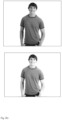
- Fig. 1 and fig. 2 show images or photos illustrating the color correction or color change in the image or photo obtained by the present method.
- Fig. 1 schematically illustrates an example of reducing or removing light spilling in color correction of images.
- green spill from the background in a subject's hair is removed by using the present method.
- the left image in fig. 1a is a part of an original image of a subject.
- the background is green. It is seen, in the color version of the figures, that some of the subject's hair looks green, in particular the single hair strands (4) that sticks out from the rest of the hair.
- the right image in fig. 1a is the original image shown in grey scale where three regions are indicated.
- the first region, marked 1 is the region of the image where light from the background is spilling onto the subject, and where the colors should be corrected.
- the second region, marked 2 is the background of the image, in this case the screen in the photo studio, such as a green screen, where the colors will be replaced with those of the correction image.
- the third region, marked 3, is a subset of the foreground of the image, in this case the subject's face, where the colors are assumed to be correct in the image
- the top left image shows the original, not corrected image, in red, green, and blue (RGB) color channels. From this image, the green spill from the background into the subject's hair 4 in the first region is very clear.
- the top right image is the color corrected image, in RGB color channels with an alpha channel overlaid. From this image it is very clear that the green spill in the subject's hair in the first region has been removed.
- This image may be a corrected image based on a corrected region of a corrected image.
- the corrected image may be based, at least in part, on one or more recoloring image(s).
- a first recoloring image may correspond to the red color channel of an RGB color image.
- a second recoloring image may correspond to the green color channel of an RGB color image.
- a third recoloring image may correspond to the blue color channel of an RGB color image.
- the bottom left image shows the original, not corrected image, in the green color channel only. From this image, the green spill from the background into the subject's hair in the first region can be seen, but it is less clear than in the top left image in RGB channels.
- the bottom right image is the color corrected image, in the green color channel only, i.e., this image may be based on a recoloring image. Since the color channel is the green channel, the image may be based on a second recoloring image corresponding to the green color channel of an RGB color image. From this image it can be seen that the green spill in the subject's hair in the first region has been removed, but it is less clear than in the top right image in RGB channels.
- Fig. 2 schematically illustrates an example of color correction in an image.
- Fig. 2 shows how to change the color of an object in an image, in this case changing the color of a T-shirt worn by the subject in the image.
- This example clearly illustrates the method, also using black-white and grey scale images.
- the regions may be determined from user inputs, and may not require using any alpha masks at all. Alternatively, the regions may be determined by an automatic region identifier and/or by a combination of an automatic region identifier and user input.
- the top image shows the original, not corrected image, in RGB color channels.
- the subject's T-shirt is brown.
- the bottom image shows the regions which the image is divided into by a user.
- the first region, marked 1 is the region of the image where the colors should be corrected or changed.
- the second region, marked 2 is a region separate from, but surrounded by, the first region.
- the colors of the first region are to be determined using the method described herein.
- the colors in the second region will be replaced with the colors of the correction image.
- the third region, marked 3 is the background of the image, in this case the screen in the photo studio, such as a white screen, where the colors are assumed to be correct in the image.
- the first region and second region in this image are an example of regions, where the second region is surrounded by the first region, and where the first and the second region are disjoint regions.
- the top image is the color corrected or color changed image in RGB color channels, where the color of the T-shirt has been changed to blue from the original brown color as seen in the top image in fig. 2a ).
- this color corrected or color changed image may be based, at least in part, on one or more recoloring image(s).
- a first recoloring image may correspond to the red color channel of an RGB color image.
- a second recoloring image may correspond to the green color channel of an RGB color image.
- a third recoloring image may correspond to the blue color channel of an RGB color image.
- the bottom image is the original image in the red color channel only.
- the image is the color corrected image in the red color channel only.
- the corrected image may be based, at least in part, on a recoloring image, in this case a first recoloring image corresponding to the red color channel of an RGB color image.
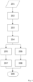
- Fig. 3 to fig. 8 show schematic flow charts illustrating the steps of the present method.
- Fig. 3 schematically illustrates an example embodiment of the invention, where a basic image is obtained (101) and the Laplacian matrix of the image is determined (102).
- the first region is obtained (103), a second region is obtained (104) and the first recoloring image is obtained (105). Finally, the first corrected image is obtained (106) and outputted (107).
- Fig. 4 schematically illustrates an embodiment of the invention, where the image has two color channels.
- the steps 201-204 are similar to steps 101-104 in fig. 3 .
- a first recoloring image is obtained (205) and a second recoloring image (206) is obtained.
- a first corrected image is determined (207).
- a second corrected image is determined (208).
- the final corrected image is outputted based on the first and the second corrected images (209).
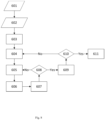
- Fig. 5 schematically illustrates an embodiment of the invention, where the basic image has an arbitrary number of color channels K.
- the steps 301-304 are similar to steps 101-104 in fig. 3 .
- First the integer k is set equal to 1 (305).
- the k'th recoloring image is obtained (306) and the k'th corrected image is determined (307) based on this.
- Fig. 6 schematically illustrates an example of automatically obtaining a region from an image.
- the basic image is obtained (401).
- an alpha mask for the image is obtained (402) before a region R is determined by numerical calculations based on the alpha mask (403).
- the region is obtained as R (404).
- Fig. 7 schematically illustrates an example of obtaining a region from an image based on user input.
- the basic image is obtained (501) and displayed to the user (502).
- the user specifies a region R using, e.g. a graphical user interface (503).
- the region is obtained as R (504).
- Fig. 8 schematically illustrates an example of obtaining a Laplacian matrix for an image with N pixels.
- the basic image with N pixels is obtained (601).
- a distance or similarity function d(x i ,x j ) between two pixels x i and x j is specified (602).
- the first counter i is set equal to 1 (603) and the second counter j is set equal to 1 (604).
- the function value d(x i ,x j ) is calculated (605) and the ( i , j )'th element of the adjacency matrix A is set equal to this value (606).
- j is incremented by one (607), and if the condition j > N (608) is not fulfilled the next step is 605. If the condition is fulfilled, the next step is to increment i by one (610). If the condition i>N (610) is not fulfilled, the next step is 604. If the condition is fulfilled, the Laplacian matrix is obtained from A (611).
- Fig. 9 schematically illustrates an example of an apparatus for color correction of an image.
- the apparatus 712 comprises a processing device 714.
- the processing device is configured for obtaining an image.
- the processing device is configured for determining a Laplacian matrix of the image.
- the processing device is configured for obtaining a first region of the image, where the first region is indicative of a part of the image to be color corrected.
- the processing device is configured for obtaining a second region of the image.
- the processing device is configured for obtaining a first recoloring image based on the second region.
- the processing device is configured for determining a first corrected region of a first corrected image based on the Laplacian matrix and the first recoloring image.
- the processing device is configured for obtaining and/or outputting a corrected image based on the first corrected region of the first corrected image.
- the apparatus 712 comprises an interface 716 configured for receiving and/or transmitting data, such as the image and/or the corrected image.
- the interface 716 is connected to the processing device 714.
- the interface 716 is configured for receiving and/or obtaining the image or basic image to be processed by the processing device 714.
- the interface 716 is configured for transmitting and/or outputting the corrected image which has been processed by the processing device 714.
- the apparatus 712 comprises a memory unit 718.
- the memory unit is connected to the processing device 714.
- the memory unit 718 is configured for storing the processed data, such as the processed image, such as the corrected image, processed by the processing device 714.
Landscapes
- Engineering & Computer Science (AREA)
- Physics & Mathematics (AREA)
- General Physics & Mathematics (AREA)
- Theoretical Computer Science (AREA)
- Computer Vision & Pattern Recognition (AREA)
- Image Processing (AREA)
Claims (15)
- Verfahren zur Farbkorrektur eines Bilds in einer Verarbeitungsvorrichtung, das Verfahren umfassend:Erhalten (101) eines Bilds;Bestimmen (102) einer Laplace-Matrix des Bilds;Erhalten (103) eines ersten Bereichs des Bilds, wobei der erste Bereich einen Teil des Bilds angibt, der farbkorrigiert werden soll;Erhalten (104) eines zweiten Bereichs des Bilds, wobei der zweite Bereich einem Hintergrund des Bilds entspricht;Erhalten (105) eines ersten Recoloring-Bilds basierend auf dem zweiten Bereich durch Anpassen eines Farbwerts von mindestens einem Teil des Hintergrunds;Bestimmen eines ersten korrigierten Bilds basierend auf der Laplace-Matrix unddem ersten Recoloring-Bild, wobei das erste korrigierte Bild den ersten korrigierten Bereich aufweist; undErhalten (106) und Ausgeben (107) eines Ausgabebilds basierend auf dem ersten korrigierten Bild.
- Verfahren nach einem der vorhergehenden Ansprüche, das Verfahren umfassend:Erhalten eines zweiten Recoloring-Bilds basierend auf dem zweiten Bereich; undBestimmen eines zweiten korrigierten Bilds basierend auf der Laplace-Matrix und dem zweiten Recoloring-Bild.
- Verfahren nach einem der vorhergehenden Ansprüche, das Verfahren umfassend Erhalten eines dritten Recoloring-Bilds basierend auf dem zweiten Bereich; und
Bestimmen eines dritten korrigierten Bilds basierend auf der Laplace-Matrix und dem dritten Recoloring-Bild. - Verfahren nach Anspruch 3, wobei mindestens eines des ersten korrigierten Bilds, des zweiten korrigierten Bilds und des dritten korrigierten Bilds auf dem ersten Bereich basiert.
- Verfahren nach einem der vorhergehenden Ansprüche, wobei Erhalten eines ersten Recoloring-Bilds basierend auf dem zweiten Bereich Anpassen eines zweiten Recoloring-Bereichs des ersten Recoloring-Bilds basierend auf dem zweiten Bereich umfasst.
- Verfahren nach Anspruch 5, wobei Erhalten eines ersten Recoloring-Bilds basierend auf dem zweiten Bereich Erhalten eines oder mehrerer Bereichsparameter des zweiten Recoloring-Bereichs umfasst.
- Verfahren nach einem der Ansprüche 1-4, wobei Erhalten eines ersten Recoloring-Bilds basierend auf dem zweiten Bereich Einstellen einer Farbe eines zweiten Recoloring-Bereichs auf eine Farbe umfasst, die sich von einer Farbe des zweiten Bereichs des Bilds unterscheidet.
- Verfahren nach einem der vorhergehenden Ansprüche, wobei Bestimmen einer Laplace-Matrix des Bilds Bestimmen einer Matting-Laplace-Matrix des Bilds umfasst, wobei die Matting-Laplace-Matrix gegeben ist durch:

- Verfahren nach einem der vorhergehenden Ansprüche, das Verfahren umfassend
Erhalten eines dritten Bereichs des Bilds, und wobei das erste Recoloring-Bild auf dem dritten Bereich basiert. - Verfahren nach Anspruch 9, wobei das erste Recoloring-Bild den dritten Bereich des Bilds umfasst.
- Verfahren nach einem der vorhergehenden Ansprüche, das Verfahren umfassend Erhalten einer Maske, die für eine Alphamatte des Bilds repräsentativ ist, und wobei das korrigierte Bild auf der Maske basiert.
- Vorrichtung zur Farbkorrektur eines Bilds, die Vorrichtung umfassend eine Verarbeitungsvorrichtung, wobei die Verarbeitungsvorrichtung konfiguriert ist zum:Erhalten (101) eines Bilds;Bestimmen (102) einer Laplace-Matrix des Bilds;Erhalten (103) eines ersten Bereichs des Bilds, wobei der erste Bereich einen Teil des Bilds angibt, der farbkorrigiert werden soll;Erhalten (104) eines zweiten Bereichs des Bilds, wobei der zweite Bereich einem Hintergrund des Bilds entspricht;Erhalten (105) eines ersten Recoloring-Bilds basierend auf dem zweiten Bereich durch Anpassen eines Farbwerts von mindestens einem Abschnitt des Hintergrunds; Bestimmen eines ersten korrigierten Bilds basierend auf der Laplace-Matrix und dem ersten Recoloring-Bild, wobei das erste korrigierte Bild den ersten korrigierten Bereich aufweist;
undErhalten (106) und Ausgeben (107) eines Ausgabebilds basierend auf dem ersten korrigierten Bild. - Vorrichtung nach Anspruch 12, wobei die Verarbeitungsvorrichtung ferner konfiguriert ist zum:Erhalten eines zweiten Recoloring-Bilds basierend auf dem zweiten Bereich; undBestimmen eines zweiten korrigierten Bilds basierend auf der Laplace-Matrix und dem zweiten Recoloring-Bild.
- Vorrichtung nach einem der Ansprüche 12 oder 13, wobei die Verarbeitungsvorrichtung ferner konfiguriert ist zum:Erhalten eines dritten Recoloring-Bilds basierend auf dem zweiten Bereich; undBestimmen eines dritten korrigierten Bilds basierend auf der Laplace-Matrix und dem dritten Recoloring-Bild.
- Vorrichtung nach einem der Ansprüche 12 bis 14, wobei die Verarbeitungsvorrichtung ferner konfiguriert ist zum:Erhalten einer Maske, die für eine Alphamatte des Bilds repräsentativ ist, undwobei das korrigierte Bild auf der Maske basiert.
Applications Claiming Priority (2)
| Application Number | Priority Date | Filing Date | Title |
|---|---|---|---|
| EP15187328 | 2015-09-29 | ||
| PCT/EP2016/072812 WO2017055204A1 (en) | 2015-09-29 | 2016-09-26 | Method and apparatus for correction of an image |
Publications (2)
| Publication Number | Publication Date |
|---|---|
| EP3357035A1 EP3357035A1 (de) | 2018-08-08 |
| EP3357035B1 true EP3357035B1 (de) | 2023-05-31 |
Family
ID=54293035
Family Applications (1)
| Application Number | Title | Priority Date | Filing Date |
|---|---|---|---|
| EP16777616.0A Active EP3357035B1 (de) | 2015-09-29 | 2016-09-26 | Verfahren und vorrichtung zur korrektur eines bildes |
Country Status (4)
| Country | Link |
|---|---|
| US (1) | US10789689B2 (de) |
| EP (1) | EP3357035B1 (de) |
| CN (1) | CN108352055B (de) |
| WO (1) | WO2017055204A1 (de) |
Families Citing this family (3)
| Publication number | Priority date | Publication date | Assignee | Title |
|---|---|---|---|---|
| CN112395950B (zh) * | 2020-10-22 | 2023-12-19 | 浙江蓝鸽科技有限公司 | 教室智能考勤方法及系统 |
| CN112883821B (zh) * | 2021-01-27 | 2024-02-20 | 维沃移动通信有限公司 | 图像处理方法、装置及电子设备 |
| CN114187215A (zh) * | 2021-11-17 | 2022-03-15 | 青海师范大学 | 基于图像分割的局部重着色算法 |
Citations (1)
| Publication number | Priority date | Publication date | Assignee | Title |
|---|---|---|---|---|
| US20100061628A1 (en) * | 2008-09-08 | 2010-03-11 | Hideshi Yamada | Image processing apparatus, image processing method, and program |
Family Cites Families (8)
| Publication number | Priority date | Publication date | Assignee | Title |
|---|---|---|---|---|
| US6009209A (en) * | 1997-06-27 | 1999-12-28 | Microsoft Corporation | Automated removal of red eye effect from a digital image |
| US6553140B1 (en) * | 1999-04-16 | 2003-04-22 | Avid Technology, Inc. | Method and system for spill correction |
| US20070165966A1 (en) * | 2005-07-15 | 2007-07-19 | Yissum Research Development Co. | Closed form method and system for matting a foreground object in an image having a background |
| US8175384B1 (en) * | 2008-03-17 | 2012-05-08 | Adobe Systems Incorporated | Method and apparatus for discriminative alpha matting |
| CN100565584C (zh) * | 2008-03-25 | 2009-12-02 | 武汉大学 | 一种具有纠偏性的自然图像抠图的全局优化方法 |
| CN102567727B (zh) * | 2010-12-13 | 2014-01-01 | 中兴通讯股份有限公司 | 一种背景目标替换方法和装置 |
| CN102779351B (zh) * | 2012-06-08 | 2016-12-21 | 温州大学 | 基于局部线性模型优化的交互式灰度图像彩色化方法 |
| CN105893649B (zh) * | 2015-03-23 | 2019-02-01 | 温州大学 | 一种基于最优化模型的交互式图像重新着色方法 |
-
2016
- 2016-09-26 WO PCT/EP2016/072812 patent/WO2017055204A1/en not_active Ceased
- 2016-09-26 US US15/759,771 patent/US10789689B2/en not_active Expired - Fee Related
- 2016-09-26 EP EP16777616.0A patent/EP3357035B1/de active Active
- 2016-09-26 CN CN201680056725.XA patent/CN108352055B/zh not_active Expired - Fee Related
Patent Citations (1)
| Publication number | Priority date | Publication date | Assignee | Title |
|---|---|---|---|---|
| US20100061628A1 (en) * | 2008-09-08 | 2010-03-11 | Hideshi Yamada | Image processing apparatus, image processing method, and program |
Also Published As
| Publication number | Publication date |
|---|---|
| US10789689B2 (en) | 2020-09-29 |
| CN108352055A (zh) | 2018-07-31 |
| CN108352055B (zh) | 2022-05-31 |
| US20190050972A1 (en) | 2019-02-14 |
| WO2017055204A1 (en) | 2017-04-06 |
| EP3357035A1 (de) | 2018-08-08 |
Similar Documents
| Publication | Publication Date | Title |
|---|---|---|
| US7636485B2 (en) | Method and system for enhancing portrait images that are processed in a batch mode | |
| US7675647B2 (en) | Apparatus, method, and program for editing images | |
| EP1130899B1 (de) | Verfahren, Vorrichtung und Speichermedium für Bildverarbeitung | |
| US20090278859A1 (en) | Closed form method and system for matting a foreground object in an image having a background | |
| CA2424963A1 (en) | Method and system for enhancing portrait images | |
| US5454050A (en) | Cut mask preparation method and apparatus | |
| EP3330920A1 (de) | Verfahren zum einsetzen fehlender regionen in einem bild eines multimediainhalts, entsprechendes computerprogrammprodukt und vorrichtung | |
| JP2008243059A (ja) | 画像処理装置及び画像処理方法 | |
| EP3816942A1 (de) | Bildverarbeitungsverfahren zur einstellung von transparenzwerten und farbwerten von pixeln in einem virtuellen bild | |
| US10789689B2 (en) | Method and apparatus for correction of an image | |
| KR20220012789A (ko) | 시설 평면도에 포함된 기호 분석 장치 및 방법 | |
| EP3143549B1 (de) | Segmentierungsbasierte bildumwandlung | |
| EP2765555B1 (de) | Bildbeurteilungsvorrichtung, bildauswahlvorrichtung, bildbeurteilungsverfahren, aufzeichnungsmedium und programm | |
| JP4519681B2 (ja) | 人物の唇領域マスクデータの作成方法および作成装置 | |
| US20230290005A1 (en) | Method and system for visualizing dyed hair image | |
| KR102066412B1 (ko) | 전경 영상 추출 장치 및 방법 | |
| JP2721107B2 (ja) | 映像特徴処理方法 | |
| US20190132479A1 (en) | Image processing apparatus, image processing method, and program | |
| JP2009059009A (ja) | 色補正画像画像の作成方法と色補正画像作成装置 | |
| Masia et al. | Content-aware reverse tone mapping | |
| JP2008172318A (ja) | 画像処理装置 | |
| JP2009016940A (ja) | フレーム画像の揃い補正処理装置及び揃い補正処理方法 | |
| JP4415650B2 (ja) | 画像処理方法及び画像処理装置 | |
| CN120147114B (zh) | 一种图像智能缩放方法 | |
| JP2528526B2 (ja) | Rgb画像からymc画像への色変換方法及び装置 |
Legal Events
| Date | Code | Title | Description |
|---|---|---|---|
| STAA | Information on the status of an ep patent application or granted ep patent |
Free format text: STATUS: UNKNOWN |
|
| STAA | Information on the status of an ep patent application or granted ep patent |
Free format text: STATUS: THE INTERNATIONAL PUBLICATION HAS BEEN MADE |
|
| PUAI | Public reference made under article 153(3) epc to a published international application that has entered the european phase |
Free format text: ORIGINAL CODE: 0009012 |
|
| STAA | Information on the status of an ep patent application or granted ep patent |
Free format text: STATUS: REQUEST FOR EXAMINATION WAS MADE |
|
| 17P | Request for examination filed |
Effective date: 20180411 |
|
| AK | Designated contracting states |
Kind code of ref document: A1 Designated state(s): AL AT BE BG CH CY CZ DE DK EE ES FI FR GB GR HR HU IE IS IT LI LT LU LV MC MK MT NL NO PL PT RO RS SE SI SK SM TR |
|
| AX | Request for extension of the european patent |
Extension state: BA ME |
|
| RAP1 | Party data changed (applicant data changed or rights of an application transferred) |
Owner name: ALTOSTRATUS CAPITAL LLC |
|
| DAV | Request for validation of the european patent (deleted) | ||
| DAX | Request for extension of the european patent (deleted) | ||
| STAA | Information on the status of an ep patent application or granted ep patent |
Free format text: STATUS: EXAMINATION IS IN PROGRESS |
|
| 17Q | First examination report despatched |
Effective date: 20200604 |
|
| GRAP | Despatch of communication of intention to grant a patent |
Free format text: ORIGINAL CODE: EPIDOSNIGR1 |
|
| STAA | Information on the status of an ep patent application or granted ep patent |
Free format text: STATUS: GRANT OF PATENT IS INTENDED |
|
| INTG | Intention to grant announced |
Effective date: 20221223 |
|
| GRAS | Grant fee paid |
Free format text: ORIGINAL CODE: EPIDOSNIGR3 |
|
| GRAA | (expected) grant |
Free format text: ORIGINAL CODE: 0009210 |
|
| STAA | Information on the status of an ep patent application or granted ep patent |
Free format text: STATUS: THE PATENT HAS BEEN GRANTED |
|
| AK | Designated contracting states |
Kind code of ref document: B1 Designated state(s): AL AT BE BG CH CY CZ DE DK EE ES FI FR GB GR HR HU IE IS IT LI LT LU LV MC MK MT NL NO PL PT RO RS SE SI SK SM TR |
|
| REG | Reference to a national code |
Ref country code: GB Ref legal event code: FG4D Ref country code: CH Ref legal event code: EP |
|
| REG | Reference to a national code |
Ref country code: DE Ref legal event code: R096 Ref document number: 602016079713 Country of ref document: DE |
|
| REG | Reference to a national code |
Ref country code: AT Ref legal event code: REF Ref document number: 1571396 Country of ref document: AT Kind code of ref document: T Effective date: 20230615 |
|
| REG | Reference to a national code |
Ref country code: IE Ref legal event code: FG4D |
|
| REG | Reference to a national code |
Ref country code: LT Ref legal event code: MG9D |
|
| REG | Reference to a national code |
Ref country code: NL Ref legal event code: MP Effective date: 20230531 |
|
| REG | Reference to a national code |
Ref country code: AT Ref legal event code: MK05 Ref document number: 1571396 Country of ref document: AT Kind code of ref document: T Effective date: 20230531 |
|
| PG25 | Lapsed in a contracting state [announced via postgrant information from national office to epo] |
Ref country code: SE Free format text: LAPSE BECAUSE OF FAILURE TO SUBMIT A TRANSLATION OF THE DESCRIPTION OR TO PAY THE FEE WITHIN THE PRESCRIBED TIME-LIMIT Effective date: 20230531 Ref country code: NO Free format text: LAPSE BECAUSE OF FAILURE TO SUBMIT A TRANSLATION OF THE DESCRIPTION OR TO PAY THE FEE WITHIN THE PRESCRIBED TIME-LIMIT Effective date: 20230831 Ref country code: ES Free format text: LAPSE BECAUSE OF FAILURE TO SUBMIT A TRANSLATION OF THE DESCRIPTION OR TO PAY THE FEE WITHIN THE PRESCRIBED TIME-LIMIT Effective date: 20230531 Ref country code: AT Free format text: LAPSE BECAUSE OF FAILURE TO SUBMIT A TRANSLATION OF THE DESCRIPTION OR TO PAY THE FEE WITHIN THE PRESCRIBED TIME-LIMIT Effective date: 20230531 |
|
| PG25 | Lapsed in a contracting state [announced via postgrant information from national office to epo] |
Ref country code: RS Free format text: LAPSE BECAUSE OF FAILURE TO SUBMIT A TRANSLATION OF THE DESCRIPTION OR TO PAY THE FEE WITHIN THE PRESCRIBED TIME-LIMIT Effective date: 20230531 Ref country code: PL Free format text: LAPSE BECAUSE OF FAILURE TO SUBMIT A TRANSLATION OF THE DESCRIPTION OR TO PAY THE FEE WITHIN THE PRESCRIBED TIME-LIMIT Effective date: 20230531 Ref country code: NL Free format text: LAPSE BECAUSE OF FAILURE TO SUBMIT A TRANSLATION OF THE DESCRIPTION OR TO PAY THE FEE WITHIN THE PRESCRIBED TIME-LIMIT Effective date: 20230531 Ref country code: LV Free format text: LAPSE BECAUSE OF FAILURE TO SUBMIT A TRANSLATION OF THE DESCRIPTION OR TO PAY THE FEE WITHIN THE PRESCRIBED TIME-LIMIT Effective date: 20230531 Ref country code: LT Free format text: LAPSE BECAUSE OF FAILURE TO SUBMIT A TRANSLATION OF THE DESCRIPTION OR TO PAY THE FEE WITHIN THE PRESCRIBED TIME-LIMIT Effective date: 20230531 Ref country code: IS Free format text: LAPSE BECAUSE OF FAILURE TO SUBMIT A TRANSLATION OF THE DESCRIPTION OR TO PAY THE FEE WITHIN THE PRESCRIBED TIME-LIMIT Effective date: 20230930 Ref country code: HR Free format text: LAPSE BECAUSE OF FAILURE TO SUBMIT A TRANSLATION OF THE DESCRIPTION OR TO PAY THE FEE WITHIN THE PRESCRIBED TIME-LIMIT Effective date: 20230531 Ref country code: GR Free format text: LAPSE BECAUSE OF FAILURE TO SUBMIT A TRANSLATION OF THE DESCRIPTION OR TO PAY THE FEE WITHIN THE PRESCRIBED TIME-LIMIT Effective date: 20230901 |
|
| PG25 | Lapsed in a contracting state [announced via postgrant information from national office to epo] |
Ref country code: FI Free format text: LAPSE BECAUSE OF FAILURE TO SUBMIT A TRANSLATION OF THE DESCRIPTION OR TO PAY THE FEE WITHIN THE PRESCRIBED TIME-LIMIT Effective date: 20230531 |
|
| PG25 | Lapsed in a contracting state [announced via postgrant information from national office to epo] |
Ref country code: SK Free format text: LAPSE BECAUSE OF FAILURE TO SUBMIT A TRANSLATION OF THE DESCRIPTION OR TO PAY THE FEE WITHIN THE PRESCRIBED TIME-LIMIT Effective date: 20230531 |
|
| PG25 | Lapsed in a contracting state [announced via postgrant information from national office to epo] |
Ref country code: SM Free format text: LAPSE BECAUSE OF FAILURE TO SUBMIT A TRANSLATION OF THE DESCRIPTION OR TO PAY THE FEE WITHIN THE PRESCRIBED TIME-LIMIT Effective date: 20230531 Ref country code: SK Free format text: LAPSE BECAUSE OF FAILURE TO SUBMIT A TRANSLATION OF THE DESCRIPTION OR TO PAY THE FEE WITHIN THE PRESCRIBED TIME-LIMIT Effective date: 20230531 Ref country code: RO Free format text: LAPSE BECAUSE OF FAILURE TO SUBMIT A TRANSLATION OF THE DESCRIPTION OR TO PAY THE FEE WITHIN THE PRESCRIBED TIME-LIMIT Effective date: 20230531 Ref country code: PT Free format text: LAPSE BECAUSE OF FAILURE TO SUBMIT A TRANSLATION OF THE DESCRIPTION OR TO PAY THE FEE WITHIN THE PRESCRIBED TIME-LIMIT Effective date: 20231002 Ref country code: EE Free format text: LAPSE BECAUSE OF FAILURE TO SUBMIT A TRANSLATION OF THE DESCRIPTION OR TO PAY THE FEE WITHIN THE PRESCRIBED TIME-LIMIT Effective date: 20230531 Ref country code: DK Free format text: LAPSE BECAUSE OF FAILURE TO SUBMIT A TRANSLATION OF THE DESCRIPTION OR TO PAY THE FEE WITHIN THE PRESCRIBED TIME-LIMIT Effective date: 20230531 Ref country code: CZ Free format text: LAPSE BECAUSE OF FAILURE TO SUBMIT A TRANSLATION OF THE DESCRIPTION OR TO PAY THE FEE WITHIN THE PRESCRIBED TIME-LIMIT Effective date: 20230531 |
|
| REG | Reference to a national code |
Ref country code: DE Ref legal event code: R097 Ref document number: 602016079713 Country of ref document: DE |
|
| REG | Reference to a national code |
Ref country code: DE Ref legal event code: R119 Ref document number: 602016079713 Country of ref document: DE |
|
| PLBE | No opposition filed within time limit |
Free format text: ORIGINAL CODE: 0009261 |
|
| STAA | Information on the status of an ep patent application or granted ep patent |
Free format text: STATUS: NO OPPOSITION FILED WITHIN TIME LIMIT |
|
| REG | Reference to a national code |
Ref country code: CH Ref legal event code: PL |
|
| PG25 | Lapsed in a contracting state [announced via postgrant information from national office to epo] |
Ref country code: SI Free format text: LAPSE BECAUSE OF FAILURE TO SUBMIT A TRANSLATION OF THE DESCRIPTION OR TO PAY THE FEE WITHIN THE PRESCRIBED TIME-LIMIT Effective date: 20230531 |
|
| 26N | No opposition filed |
Effective date: 20240301 |
|
| PG25 | Lapsed in a contracting state [announced via postgrant information from national office to epo] |
Ref country code: LU Free format text: LAPSE BECAUSE OF NON-PAYMENT OF DUE FEES Effective date: 20230926 |
|
| REG | Reference to a national code |
Ref country code: BE Ref legal event code: MM Effective date: 20230930 |
|
| GBPC | Gb: european patent ceased through non-payment of renewal fee |
Effective date: 20230926 |
|
| PG25 | Lapsed in a contracting state [announced via postgrant information from national office to epo] |
Ref country code: SI Free format text: LAPSE BECAUSE OF FAILURE TO SUBMIT A TRANSLATION OF THE DESCRIPTION OR TO PAY THE FEE WITHIN THE PRESCRIBED TIME-LIMIT Effective date: 20230531 Ref country code: LU Free format text: LAPSE BECAUSE OF NON-PAYMENT OF DUE FEES Effective date: 20230926 Ref country code: IT Free format text: LAPSE BECAUSE OF FAILURE TO SUBMIT A TRANSLATION OF THE DESCRIPTION OR TO PAY THE FEE WITHIN THE PRESCRIBED TIME-LIMIT Effective date: 20230531 Ref country code: MC Free format text: LAPSE BECAUSE OF FAILURE TO SUBMIT A TRANSLATION OF THE DESCRIPTION OR TO PAY THE FEE WITHIN THE PRESCRIBED TIME-LIMIT Effective date: 20230531 |
|
| REG | Reference to a national code |
Ref country code: IE Ref legal event code: MM4A |
|
| PG25 | Lapsed in a contracting state [announced via postgrant information from national office to epo] |
Ref country code: IE Free format text: LAPSE BECAUSE OF NON-PAYMENT OF DUE FEES Effective date: 20230926 |
|
| PG25 | Lapsed in a contracting state [announced via postgrant information from national office to epo] |
Ref country code: GB Free format text: LAPSE BECAUSE OF NON-PAYMENT OF DUE FEES Effective date: 20230926 |
|
| PG25 | Lapsed in a contracting state [announced via postgrant information from national office to epo] |
Ref country code: CH Free format text: LAPSE BECAUSE OF NON-PAYMENT OF DUE FEES Effective date: 20230930 |
|
| PG25 | Lapsed in a contracting state [announced via postgrant information from national office to epo] |
Ref country code: IE Free format text: LAPSE BECAUSE OF NON-PAYMENT OF DUE FEES Effective date: 20230926 Ref country code: GB Free format text: LAPSE BECAUSE OF NON-PAYMENT OF DUE FEES Effective date: 20230926 Ref country code: DE Free format text: LAPSE BECAUSE OF NON-PAYMENT OF DUE FEES Effective date: 20240403 Ref country code: CH Free format text: LAPSE BECAUSE OF NON-PAYMENT OF DUE FEES Effective date: 20230930 Ref country code: FR Free format text: LAPSE BECAUSE OF NON-PAYMENT OF DUE FEES Effective date: 20230930 |
|
| PG25 | Lapsed in a contracting state [announced via postgrant information from national office to epo] |
Ref country code: BE Free format text: LAPSE BECAUSE OF NON-PAYMENT OF DUE FEES Effective date: 20230930 |
|
| PG25 | Lapsed in a contracting state [announced via postgrant information from national office to epo] |
Ref country code: BG Free format text: LAPSE BECAUSE OF FAILURE TO SUBMIT A TRANSLATION OF THE DESCRIPTION OR TO PAY THE FEE WITHIN THE PRESCRIBED TIME-LIMIT Effective date: 20230531 |
|
| PG25 | Lapsed in a contracting state [announced via postgrant information from national office to epo] |
Ref country code: BG Free format text: LAPSE BECAUSE OF FAILURE TO SUBMIT A TRANSLATION OF THE DESCRIPTION OR TO PAY THE FEE WITHIN THE PRESCRIBED TIME-LIMIT Effective date: 20230531 |
|
| PG25 | Lapsed in a contracting state [announced via postgrant information from national office to epo] |
Ref country code: CY Free format text: LAPSE BECAUSE OF FAILURE TO SUBMIT A TRANSLATION OF THE DESCRIPTION OR TO PAY THE FEE WITHIN THE PRESCRIBED TIME-LIMIT; INVALID AB INITIO Effective date: 20160926 |
|
| PG25 | Lapsed in a contracting state [announced via postgrant information from national office to epo] |
Ref country code: HU Free format text: LAPSE BECAUSE OF FAILURE TO SUBMIT A TRANSLATION OF THE DESCRIPTION OR TO PAY THE FEE WITHIN THE PRESCRIBED TIME-LIMIT; INVALID AB INITIO Effective date: 20160926 |
|
| PG25 | Lapsed in a contracting state [announced via postgrant information from national office to epo] |
Ref country code: TR Free format text: LAPSE BECAUSE OF FAILURE TO SUBMIT A TRANSLATION OF THE DESCRIPTION OR TO PAY THE FEE WITHIN THE PRESCRIBED TIME-LIMIT Effective date: 20230531 |