EP3355589A1 - Acoustic apparatus - Google Patents
Acoustic apparatus Download PDFInfo
- Publication number
- EP3355589A1 EP3355589A1 EP17207456.9A EP17207456A EP3355589A1 EP 3355589 A1 EP3355589 A1 EP 3355589A1 EP 17207456 A EP17207456 A EP 17207456A EP 3355589 A1 EP3355589 A1 EP 3355589A1
- Authority
- EP
- European Patent Office
- Prior art keywords
- diaphragm
- axial direction
- fillers
- shape
- sheet member
- Prior art date
- Legal status (The legal status is an assumption and is not a legal conclusion. Google has not performed a legal analysis and makes no representation as to the accuracy of the status listed.)
- Granted
Links
Images

Classifications
-
- H—ELECTRICITY
- H04—ELECTRIC COMMUNICATION TECHNIQUE
- H04R—LOUDSPEAKERS, MICROPHONES, GRAMOPHONE PICK-UPS OR LIKE ACOUSTIC ELECTROMECHANICAL TRANSDUCERS; ELECTRIC HEARING AIDS; PUBLIC ADDRESS SYSTEMS
- H04R1/00—Details of transducers, loudspeakers or microphones
- H04R1/20—Arrangements for obtaining desired frequency or directional characteristics
-
- H—ELECTRICITY
- H04—ELECTRIC COMMUNICATION TECHNIQUE
- H04R—LOUDSPEAKERS, MICROPHONES, GRAMOPHONE PICK-UPS OR LIKE ACOUSTIC ELECTROMECHANICAL TRANSDUCERS; ELECTRIC HEARING AIDS; PUBLIC ADDRESS SYSTEMS
- H04R7/00—Diaphragms for electromechanical transducers; Cones
- H04R7/02—Diaphragms for electromechanical transducers; Cones characterised by the construction
- H04R7/04—Plane diaphragms
- H04R7/06—Plane diaphragms comprising a plurality of sections or layers
-
- H—ELECTRICITY
- H04—ELECTRIC COMMUNICATION TECHNIQUE
- H04R—LOUDSPEAKERS, MICROPHONES, GRAMOPHONE PICK-UPS OR LIKE ACOUSTIC ELECTROMECHANICAL TRANSDUCERS; ELECTRIC HEARING AIDS; PUBLIC ADDRESS SYSTEMS
- H04R1/00—Details of transducers, loudspeakers or microphones
- H04R1/02—Casings; Cabinets ; Supports therefor; Mountings therein
- H04R1/025—Arrangements for fixing loudspeaker transducers, e.g. in a box, furniture
-
- H—ELECTRICITY
- H04—ELECTRIC COMMUNICATION TECHNIQUE
- H04R—LOUDSPEAKERS, MICROPHONES, GRAMOPHONE PICK-UPS OR LIKE ACOUSTIC ELECTROMECHANICAL TRANSDUCERS; ELECTRIC HEARING AIDS; PUBLIC ADDRESS SYSTEMS
- H04R1/00—Details of transducers, loudspeakers or microphones
- H04R1/20—Arrangements for obtaining desired frequency or directional characteristics
- H04R1/22—Arrangements for obtaining desired frequency or directional characteristics for obtaining desired frequency characteristic only
- H04R1/28—Transducer mountings or enclosures modified by provision of mechanical or acoustic impedances, e.g. resonator, damping means
-
- H—ELECTRICITY
- H04—ELECTRIC COMMUNICATION TECHNIQUE
- H04R—LOUDSPEAKERS, MICROPHONES, GRAMOPHONE PICK-UPS OR LIKE ACOUSTIC ELECTROMECHANICAL TRANSDUCERS; ELECTRIC HEARING AIDS; PUBLIC ADDRESS SYSTEMS
- H04R1/00—Details of transducers, loudspeakers or microphones
- H04R1/20—Arrangements for obtaining desired frequency or directional characteristics
- H04R1/22—Arrangements for obtaining desired frequency or directional characteristics for obtaining desired frequency characteristic only
- H04R1/28—Transducer mountings or enclosures modified by provision of mechanical or acoustic impedances, e.g. resonator, damping means
- H04R1/2807—Enclosures comprising vibrating or resonating arrangements
- H04R1/283—Enclosures comprising vibrating or resonating arrangements using a passive diaphragm
- H04R1/2834—Enclosures comprising vibrating or resonating arrangements using a passive diaphragm for loudspeaker transducers
-
- H—ELECTRICITY
- H04—ELECTRIC COMMUNICATION TECHNIQUE
- H04R—LOUDSPEAKERS, MICROPHONES, GRAMOPHONE PICK-UPS OR LIKE ACOUSTIC ELECTROMECHANICAL TRANSDUCERS; ELECTRIC HEARING AIDS; PUBLIC ADDRESS SYSTEMS
- H04R31/00—Apparatus or processes specially adapted for the manufacture of transducers or diaphragms therefor
- H04R31/003—Apparatus or processes specially adapted for the manufacture of transducers or diaphragms therefor for diaphragms or their outer suspension
-
- H—ELECTRICITY
- H04—ELECTRIC COMMUNICATION TECHNIQUE
- H04R—LOUDSPEAKERS, MICROPHONES, GRAMOPHONE PICK-UPS OR LIKE ACOUSTIC ELECTROMECHANICAL TRANSDUCERS; ELECTRIC HEARING AIDS; PUBLIC ADDRESS SYSTEMS
- H04R7/00—Diaphragms for electromechanical transducers; Cones
- H04R7/02—Diaphragms for electromechanical transducers; Cones characterised by the construction
-
- H—ELECTRICITY
- H04—ELECTRIC COMMUNICATION TECHNIQUE
- H04R—LOUDSPEAKERS, MICROPHONES, GRAMOPHONE PICK-UPS OR LIKE ACOUSTIC ELECTROMECHANICAL TRANSDUCERS; ELECTRIC HEARING AIDS; PUBLIC ADDRESS SYSTEMS
- H04R9/00—Transducers of moving-coil, moving-strip, or moving-wire type
- H04R9/02—Details
- H04R9/025—Magnetic circuit
-
- H—ELECTRICITY
- H04—ELECTRIC COMMUNICATION TECHNIQUE
- H04R—LOUDSPEAKERS, MICROPHONES, GRAMOPHONE PICK-UPS OR LIKE ACOUSTIC ELECTROMECHANICAL TRANSDUCERS; ELECTRIC HEARING AIDS; PUBLIC ADDRESS SYSTEMS
- H04R2307/00—Details of diaphragms or cones for electromechanical transducers, their suspension or their manufacture covered by H04R7/00 or H04R31/003, not provided for in any of its subgroups
- H04R2307/029—Diaphragms comprising fibres
Definitions
- the present invention relates to an acoustic apparatus (speaker) having improved acoustic characteristics, in particular, improved acoustic characteristics in a high range.
- Speech apparatuses are required to have the ability to reproduce original sounds as accurately as possible.
- speaker components such as diaphragms have been improved in various ways.
- JP 63-59638 A discloses a diaphragm in which a plurality of composite material sheets are laminated and integrally joined.
- Each of the composite material sheets is formed of reinforcing fibers having a high modulus of longitudinal elasticity and a matrix material that binds the fibers.
- the reinforcing fibers of each composite material sheet are oriented in a radial direction with respect to a vibration direction of the diaphragm.
- the reinforcing fibers having the high modulus of longitudinal elasticity are dispersed in the matrix material such as a resin, the density decreases and the specific modulus of longitudinal elasticity (modulus of longitudinal elasticity/density) increases, and hence a diaphragm having frequency characteristics in a wide band may be obtained.
- a diaphragm such as one disclosed in JP 63-59638 A
- good characteristics as those of a diaphragm using a light metal such as magnesium can be obtained.
- frequency characteristics having a sharp resonance peak (a band with a sound pressure being characteristically higher than the sound pressures in the other frequency bands) based on an axially symmetric mode in a high range may appear.
- a specific example of the shape of a diaphragm being highly symmetric may be a rotationally symmetric shape with a small rotation angle.
- a typical example is a continuously rotationally symmetric shape around the axis thereof. The shape can be expressed by a plurality of circles whose central axes are aligned with one another when viewed in the axial direction. The rotation angle around the axis becomes infinitely small, and the shape has continuous rotation symmetry.
- An example of a method of suppressing the sharpening of the resonance peak in such a high range may be a method of decreasing the symmetry of the shape when viewed in the axial direction.
- a specific example may be an oblique-cone diaphragm or a diaphragm having a modified sectional shape.
- the oblique-cone diaphragm and the diaphragm having the modified sectional shape have complicated shapes and have difficulty in manufacturing and assembly.
- a new resonance mode may be generated due to the eccentricity or modified sectional shape.
- the invention relates to acoustic apparatuses according to the appended claims. Embodiments are disclosed in the dependent claims.
- an acoustic apparatus including a frame having an annular open portion that opens in an axial direction; a diaphragm supported by being attached to the annular open portion via a flexible edge member so as to be capable of vibrating in the axial direction; and a driving unit connected to the diaphragm at a center portion of the diaphragm, and configured to apply a driving force in the axial direction to the diaphragm.
- the diaphragm has a rotationally symmetric shape around an axis of the diaphragm when viewed in the axial direction.
- the diaphragm includes a sheet member having an orientation dispersion structure in which shape-anisotropic fillers are dispersed in a resin with long axes of the fillers oriented in one predetermined direction, and the diaphragm has mechanical characteristics having plane symmetry with respect to a plane, as a symmetry plane, including the orientation direction of the fillers and the axis.
- the shape of the diaphragm is partly changed from a typical shape (for specific example, a shape having continuous rotation symmetry around the axis), and the symmetry of the shape when viewed in the axial direction is decreased. Hence, sharpening of a resonance peak with high frequencies is suppressed.
- the shape of the diaphragm may have a partial variation around the axis.
- a driving unit applies an external force to the diaphragm having such a shape
- deformation of the diaphragm caused by the external force may also vary in accordance with the variation in the shape of the diaphragm.
- the symmetry of the vibration generated at the diaphragm may be decreased and the resonant frequency may be dispersed.
- the resonance frequency is properly dispersed, and hence appearance of a sharp resonance peak is suppressed.
- the diaphragm of the speaker according to the aspect of the present invention decreases the symmetry of vibration of the diaphragm by giving anisotropy to the mechanical strength of a member forming the diaphragm, without decreasing the symmetry of the shape of the diaphragm.
- the sheet member forming the diaphragm has the orientation dispersion structure, and the mechanical characteristics in the orientation direction differ from the mechanical characteristics in the direction orthogonal to the orientation direction, the mechanical characteristics have two-fold rotation symmetry with a rotation angle of 180 degrees around the axis.
- the resonance frequency can be efficiently dispersed without decreasing the symmetry of the shape of the diaphragm. Owing to this, with the speaker according to the aspect of the present invention, appearance of a sharp resonance peak is efficiently suppressed.
- the diaphragm may preferably include one seamless sheet member; the diaphragm may include a high-rigidity region in which the orientation direction of the fillers is parallel to a direction from a center portion to an outer circumferential portion of the diaphragm and flexural rigidity there is at a first value (e.g.
- the diaphragm may preferably have a continuously rotationally symmetric shape around the axis of the diaphragm when viewed in the axial direction.
- the shape having the continuous rotation symmetry around the axis can be expressed by a plurality of circles whose central axes are aligned with one another when viewed in the axial direction.
- the diaphragm having such a shape typically likely has isotropic mechanical characteristics around the axis, and hence a resonance peak may be likely sharpened.
- the sheet member forming the speaker has the orientation dispersion structure, and hence the mechanical characteristics have two-fold rotation symmetry with a rotation angle of 180 degrees around the axis. Accordingly, even when the shape of the diaphragm is a highly symmetric shape around the axis, a sharp resonance peak hardly appears when the diaphragm is vibrated in the axial direction. Moreover, the diaphragm with the highly symmetric shape is easily manufactured, and a peak or a dip due to the shape hardly appears in the frequency characteristics of the sound pressure, as compared with the oblique-cone diaphragm or the diaphragm with the modified sectional shape.
- the diaphragm may be preferably formed of one seamless sheet member. With the one seamless sheet member, the acoustic characteristics can be increased without a special treatment.
- the diaphragm may be preferably a vacuum-formed article or a pressure-formed article formed of a sheet member in which the fillers are dispersed in a thermoplastic resin.
- the thermoplastic resin is easily handled, and when the thermoplastic resin is heated, vacuum forming or pressure forming can be carried out.
- the vacuum forming and pressure forming can decrease the cost of the mold as compared with injection molding etc., and the manufacturing cost may be suppressed.
- the acoustic apparatus by giving anisotropy to the mechanical characteristics by using the member having the orientation dispersion structure as the sheet member forming the diaphragm, sharpening of a resonance peak in the high range can be properly suppressed, and good acoustic characteristics can be obtained.
- a defect caused by the low symmetry of the shape (appearance of a peak or a dip in the frequency characteristics of the sound pressure) hardly occurs. Accordingly, an acoustic apparatus including a diaphragm with a shape that can be relatively easily manufactured, and having good acoustic characteristics can be obtained.
- Fig. 1A is a conceptual sectional view illustrating a structure of a speaker according to the embodiment of the present invention
- Fig. 1B is a partial plan view in the X1-X2 direction illustrating a structure of a diaphragm included in the speaker.
- a shape appearing on the Y1 side in the Y1-Y2 direction is the same as that appearing on the Y2 side in the Y1-Y2 direction; thus, the plan view illustrates only the Y2 side.
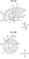
- Fig. 2A is a sectional perspective view illustrating the structure of the diaphragm of the speaker according to the embodiment
- FIG. 2B is a plan view in the X1-X2 direction illustrating the structure of the diaphragm of the speaker according to the embodiment.
- the sectional perspective view illustrates a section in which a sectional area of the diaphragm of the speaker is the maximum.
- a speaker 1 includes a frame 11 having a substantially truncated cone shape and various members attached to the frame 11.
- the frame 11 includes, at an outer circumferential edge thereof, an annular open portion 11a having a circular-ring shape and a spoke-like support 11c extending from the annular open portion 11a.
- the support 11c is indicated by a discontinuous line having cut-out holes 11b for convenience of understanding.
- a diaphragm 12 that generates a sound pressure in the speaker 1 includes a flexible edge member 12a at an outer circumferential edge of the diaphragm 12.
- the diaphragm 12 is supported by being attached to the annular open portion 11a via the flexible edge member 12a so as to be capable of vibrating in the axial direction (X1-X2 direction in Fig. 1A ).
- the diaphragm 12 has a substantially truncated cone shape and has a circular outer shape when viewed in the axial direction (X1-X2 direction).
- the diaphragm 12 includes the flexible edge member 12a at the outer circumferential edge thereof and is attached to the annular open portion 11a of the frame 11 via the flexible edge member 12a.
- the flexible edge member 12a is bonded to the annular open portion 11a of the frame 11 by using an adhesive agent. Supported by the frame 11 as described above, the diaphragm 12 can vibrate in the X1-X2 direction.
- the diaphragm 12 includes an opening (diaphragm opening) 12b at a center portion when viewed in the axial direction (X1-X2 direction).
- the diaphragm 12 is connected to a bobbin 15 at an inner circumferential surface of the diaphragm opening 12b.
- the bobbin 15 is a part of a driving unit (described later).
- a dust cap 13 having a hemispherical-cap shape is disposed on the X2 side of the diaphragm 12 in the X1-X2 direction to cover the diaphragm opening 12b.
- the dust cap 13 is a member that suppresses unstable operation of the bobbin 15 because a foreign substance enters the diaphragm opening 12b toward the X1 side in the X1-X2 direction.
- the support 11c of the frame 11 has a truncated cone shape and has a top portion (magnetic circuit mount portion 11d) on which a magnetic circuit 14 is mounted.
- the magnetic circuit 14 includes a columnar center pole 14a.
- the center pole 14a has a central axis directed in a vibration direction (axial direction (X1-X2 direction)) of the diaphragm.
- a bottom plate 14b is disposed so as to be integral with the center pole 14a.
- an annular magnet 14c is mounted on the front side (the X2 side in the X1-X2 direction) of the bottom plate 14b.
- an annular top plate 14d is mounted on the front side (the X2 side in the X1-X2 direction) of the magnet 14c.
- the provision of the magnet 14c forms an annular magnetic gap 14e between the center pole 14a and the top plate 14d.
- the bottom plate 14b and the top plate 14d form a yoke.
- the bobbin 15 On the rear side (the X1 side in the X1-X2 direction) of the diaphragm 12, the bobbin 15 having a cylindrical shape is secured. As illustrated in Fig. 1A , the bobbin 15 is inserted into the magnetic gap 14e of the magnetic circuit 14 positioned on the rear side (the X1 side in the X1-X2 direction) of the diaphragm 12.
- the bobbin 15 includes a portion inserted into the magnetic gap 14e, the portion having a side surface around which a voice coil 16 is wound.
- the bobbin 15 reciprocates in the axial direction (X1-X2 direction) in accordance with a current flowing through the voice coil 16 positioned inside the magnetic gap 14e, which causes the diaphragm 12 to vibrate and generate a sound pressure.
- a damper 17 is disposed between the diaphragm 12 and the magnetic circuit 14 in the axial direction (X1-X2 direction).
- the damper 17 is supported by the support 11c of the frame 11 at an outer circumference side of the damper 17, and supports the bobbin 15 at an inner circumference side of the damper 17.
- the damper 17 is formed of an elastic member. In a state in which no current flows through the voice coil 16, the damper 17 has a function of returning the bobbin 15 to a neutral position by using an elastic recovery force.
- the speaker 1 having such a structure can generate, as described above, a sound pressure in the axial direction X1 (X1-X2 direction) by causing a current to flow through the voice coil 16 to thereby cause the diaphragm 12 to vibrate.
- the proportionality coefficient between the magnitude of the current flowing through the voice coil 16 and the magnitude of a sound pressure to be generated is ideally the same at any frequency.
- the resonant frequency of the speaker 1 influences the frequency dependence of the sound pressure to have a peak (a band in which the sound pressure is high) and a dip (a band in which the sound pressure is low) in a specific range.
- the diaphragm 12 has a shape continuously rotationally symmetric around the axis (the line in the X1-X2 direction) like the speaker 1 illustrated in Fig. 1 , that is, when the diaphragm has a shape which may be expressed with a plurality of coaxial circles, a resonance peak in a high range is likely sharpened when viewed in the X1-X2 direction.
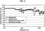
- Fig. 3 is a graph showing frequency characteristics of a speaker according to a modification of the embodiment of the present invention, together with frequency characteristics of speakers having other structures.
- the graph indicated by a gray broken line in Fig. 3 is a graph showing frequency characteristics of a speaker (hereinafter, referred to as reference speaker) including a diaphragm having mechanical characteristics isotropic around the axis (the line in the X1-X2 direction), that is, a speaker with the shape and mechanical characteristics having continuous rotation symmetry around the axis (the line in the X1-X2 direction).
- reference speaker includes a diaphragm having mechanical characteristics isotropic around the axis (the line in the X1-X2 direction), that is, a speaker with the shape and mechanical characteristics having continuous rotation symmetry around the axis (the line in the X1-X2 direction).
- the diaphragm 12 of the speaker 1 is formed of a sheet member that has an orientation dispersion structure in which shape-anisotropic fillers FB are dispersed in a resin with the long axes thereof oriented in one predetermined direction (specifically, orientation direction D1 along the Y1-Y2 direction) as illustrated in Figs. 2A and 2B .
- the sheet member having the orientation dispersion structure to form the diaphragm 12 improves the mechanical characteristics of the diaphragm compared with a case in which the fillers FB are not contained. As a result, the mechanical characteristics of the diaphragm 12 can be improved.
- Examples of the shape-anisotropic fillers FB include carbon-based materials, such as carbon fiber and carbon nanotubes, and oxide-based materials, such as glass fiber.
- the length of each of the fillers FB may be any length. Non-limiting examples of the length are a length between 0.01 to 10 mm inclusive, or may be preferably a length between 0.1 mm to several millimeters inclusive from a viewpoint of ease of handling.
- the ratio of the length of the major axis of each filler FB to the length of the minor axis of the filler FB, what is called the aspect ratio, may be any ratio.
- the aspect ratio of each filler FB may be preferably 5 or higher.
- the type of the resin contained in the sheet member is not limited. Non-limiting examples of the resin are polyolefin, such as polyethylene and polypropylene; polyester, such as polyethylene terephthalate; polyamide, such as nylon 6,6; polyvinyl chloride; and polyimide.
- the method of manufacturing the sheet member may be any method, as long as the sheet member can have an appropriate orientation dispersion structure.
- Specific examples of the method of manufacturing the sheet member are extrusion forming, expansion, and blow forming.
- the sheet member may preferably contain a filler having high orientation dispersion properties, so as to have high in-plane uniformity.
- the sheet member is preferably an extrusion-formed article. With such a sheet member being the extrusion-formed article, the uniformity of the material of the sheet member as a constituent material of the diaphragm 12 is increased, which may make it easy to realize the speaker 1 having excellent quality uniformity.
- the diaphragm 12 is formed of such a sheet member.
- the manufacturing method of the diaphragm 12 is not particularly limited.
- the manufacturing method of the diaphragm is typically vacuum forming or pressure forming of forming a sheet member with use of a mold having an exhaust hole. By heating the sheet member during vacuum forming etc., formability may be increased.
- the sheet member Since the sheet member has the orientation dispersion structure as described above, the sheet member has anisotropic mechanical characteristics. Specifically, the mechanical characteristics in the orientation direction D1 differ from the mechanical characteristics in a direction orthogonal to the orientation direction D1.
- the modulus of longitudinal elasticity and specific frequency are typically relatively high in the orientation direction D1, and the tensile elasticity is relatively high in the direction orthogonal to the orientation direction D1.
- the sheet member has the orientation dispersion structure in the diaphragm 12 formed by including the sheet member, the mechanical characteristics, in particular, the modulus of longitudinal elasticity of the diaphragm 12 is increased as compared with a diaphragm formed of a sheet member in which fillers are not dispersed.
- the sheet member has the anisotropic mechanical characteristics, the mechanical characteristics of the diaphragm 12 in the orientation direction D1 of the sheet member differ from the mechanical characteristics of the diaphragm 12 in the direction orthogonal to the orientation direction D1.
- the mechanical characteristics of the diaphragm 12 have two-fold rotation symmetry with a rotation angle of 180 degrees around the axis (the line in the X1-X2 direction).
- the shape of the diaphragm 12 of the speaker 1 according to the embodiment of the present invention has continuous rotation symmetry around the axis (the line in the X1-X2 direction), and the mechanical characteristics of the diaphragm 12 have two-fold rotation symmetry.
- rotation symmetry two-fold rotation symmetry has the lowest symmetry. Due to this, when the diaphragm 12 vibrates, a resonance peak in a high range is less likely sharpened in the frequency characteristics of the sound pressure.
- the diaphragm 12 includes a high-rigidity region in which the orientation direction of the fillers is parallel to a direction from a center portion to an outer circumferential portion of the diaphragm 12 and flexural rigidity there is high (i.e. at a first value) when it is attempted to bend an area between the center portion and the outer circumferential portion of the diaphragm 12, and a low-rigidity region in which the orientation direction of the fillers is orthogonal to the direction from the center portion to the outer circumferential portion of the diaphragm 12 and flexural rigidity there is low (i.e.
- Fig. 3 shows the frequency characteristics of the speaker 1 according to an aspect of the present invention by using a solid line. As shown in Fig. 3 , there is no sharp peak in a band around 5 kHz whereas a peak is clearly found in the graph indicated by the gray broken line (the frequency characteristics of the reference speaker).
- Fig. 3 shows the frequency characteristics of a speaker including an oblique-cone diaphragm (black broken line), and the frequency characteristics of a speaker including a diaphragm with a modified sectional shape (black fine dotted line), although the basic shape of each of the speakers is common to the shape of the speaker 1 according to the aspect of the present invention.
- the outer shape of the diaphragm with the modified sectional shape has, for example, an S-shaped ridge line, the shape which has eight-fold rotation symmetry around the axis (the line in X1-X2 direction).
- a dip appears with frequencies around 5 kHz. This may be caused by rolling of the diaphragm having an eccentric shape.
- a strong peak is found with frequencies around 5 kHz although the intensity thereof is slightly lower than that of the reference speaker. This may be because the diaphragm still has a highly symmetric shape around the axis (the line in the X1-X2 direction).
- the diaphragm 12 may be a formed article having a laminated structure including the sheet member having the above-described orientation dispersion structure and an exterior sheet.
- the provision of the exterior sheet improves the design of the diaphragm.
- the weight of the diaphragm is increased, and hence the acoustic characteristics may be decreased (for example, a sound pressure in a high range may be decreased).
Landscapes
- Engineering & Computer Science (AREA)
- Physics & Mathematics (AREA)
- Acoustics & Sound (AREA)
- Signal Processing (AREA)
- Multimedia (AREA)
- Health & Medical Sciences (AREA)
- Otolaryngology (AREA)
- Manufacturing & Machinery (AREA)
- Diaphragms For Electromechanical Transducers (AREA)
- Audible-Bandwidth Dynamoelectric Transducers Other Than Pickups (AREA)
- Details Of Audible-Bandwidth Transducers (AREA)
Abstract

Description
- The present invention relates to an acoustic apparatus (speaker) having improved acoustic characteristics, in particular, improved acoustic characteristics in a high range.
- Acoustic apparatuses (speakers) are required to have the ability to reproduce original sounds as accurately as possible. To satisfy this requirement, speaker components such as diaphragms have been improved in various ways.
- For example,
JP 63-59638 A - With use of a diaphragm such as one disclosed in
JP 63-59638 A - An example of a method of suppressing the sharpening of the resonance peak in such a high range may be a method of decreasing the symmetry of the shape when viewed in the axial direction. A specific example may be an oblique-cone diaphragm or a diaphragm having a modified sectional shape.
- However, the oblique-cone diaphragm and the diaphragm having the modified sectional shape have complicated shapes and have difficulty in manufacturing and assembly. A new resonance mode may be generated due to the eccentricity or modified sectional shape. When the frequency dependency of the sound pressure is measured, a spectrum having a characteristic peak or dip (a band in which the sound pressure is characteristically lower than the sound pressures in the other frequency bands) may be obtained.
- Regarding such circumstances in the related art, it is an object of the present invention to provide an acoustic apparatus in which sharpening of a resonance peak in a high range is properly suppressed and which has good acoustic characteristics.
- The invention relates to acoustic apparatuses according to the appended claims. Embodiments are disclosed in the dependent claims.
- According to an aspect, there is provided an acoustic apparatus (speaker) including a frame having an annular open portion that opens in an axial direction; a diaphragm supported by being attached to the annular open portion via a flexible edge member so as to be capable of vibrating in the axial direction; and a driving unit connected to the diaphragm at a center portion of the diaphragm, and configured to apply a driving force in the axial direction to the diaphragm. The diaphragm has a rotationally symmetric shape around an axis of the diaphragm when viewed in the axial direction. The diaphragm includes a sheet member having an orientation dispersion structure in which shape-anisotropic fillers are dispersed in a resin with long axes of the fillers oriented in one predetermined direction, and the diaphragm has mechanical characteristics having plane symmetry with respect to a plane, as a symmetry plane, including the orientation direction of the fillers and the axis.
- As described above, regarding the oblique-cone diaphragm or the diaphragm having the modified sectional shape, the shape of the diaphragm is partly changed from a typical shape (for specific example, a shape having continuous rotation symmetry around the axis), and the symmetry of the shape when viewed in the axial direction is decreased. Hence, sharpening of a resonance peak with high frequencies is suppressed. By partly changing the shape of the diaphragm, the shape of the diaphragm may have a partial variation around the axis. When a driving unit applies an external force to the diaphragm having such a shape, deformation of the diaphragm caused by the external force may also vary in accordance with the variation in the shape of the diaphragm. As a result, when the diaphragm is vibrated by the driving unit, the symmetry of the vibration generated at the diaphragm may be decreased and the resonant frequency may be dispersed. The resonance frequency is properly dispersed, and hence appearance of a sharp resonance peak is suppressed.
- The diaphragm of the speaker according to the aspect of the present invention decreases the symmetry of vibration of the diaphragm by giving anisotropy to the mechanical strength of a member forming the diaphragm, without decreasing the symmetry of the shape of the diaphragm. Specifically, since the sheet member forming the diaphragm has the orientation dispersion structure, and the mechanical characteristics in the orientation direction differ from the mechanical characteristics in the direction orthogonal to the orientation direction, the mechanical characteristics have two-fold rotation symmetry with a rotation angle of 180 degrees around the axis. Hence, the resonance frequency can be efficiently dispersed without decreasing the symmetry of the shape of the diaphragm. Owing to this, with the speaker according to the aspect of the present invention, appearance of a sharp resonance peak is efficiently suppressed.
- In the above-described acoustic device (speaker), the diaphragm may preferably include one seamless sheet member; the diaphragm may include a high-rigidity region in which the orientation direction of the fillers is parallel to a direction from a center portion to an outer circumferential portion of the diaphragm and flexural rigidity there is at a first value (e.g. high) when it is attempted to bend an area between the center portion and the outer circumferential portion of the diaphragm, and a low-rigidity region in which the orientation direction of the fillers is orthogonal to the direction from the center portion to the outer circumferential portion of the diaphragm and flexural rigidity there is at a second value lower than the first value (e.g. low) when it is attempted to bend an area between the center portion and the outer circumferential portion of the diaphragm; and flexural rigidity may be continuously decreased from the high-rigidity region to the low-rigidity region.
- In the above-described acoustic device (speaker), the diaphragm may preferably have a continuously rotationally symmetric shape around the axis of the diaphragm when viewed in the axial direction. As described above, the shape having the continuous rotation symmetry around the axis can be expressed by a plurality of circles whose central axes are aligned with one another when viewed in the axial direction. The diaphragm having such a shape typically likely has isotropic mechanical characteristics around the axis, and hence a resonance peak may be likely sharpened. However, as described above, in the diaphragm of the speaker according to the aspect of the present invention, the sheet member forming the speaker has the orientation dispersion structure, and hence the mechanical characteristics have two-fold rotation symmetry with a rotation angle of 180 degrees around the axis. Accordingly, even when the shape of the diaphragm is a highly symmetric shape around the axis, a sharp resonance peak hardly appears when the diaphragm is vibrated in the axial direction. Moreover, the diaphragm with the highly symmetric shape is easily manufactured, and a peak or a dip due to the shape hardly appears in the frequency characteristics of the sound pressure, as compared with the oblique-cone diaphragm or the diaphragm with the modified sectional shape.
- In the above-described acoustic device (speaker), the diaphragm may be preferably formed of one seamless sheet member. With the one seamless sheet member, the acoustic characteristics can be increased without a special treatment.
- In the above-described acoustic device (speaker), the diaphragm may be preferably a vacuum-formed article or a pressure-formed article formed of a sheet member in which the fillers are dispersed in a thermoplastic resin. The thermoplastic resin is easily handled, and when the thermoplastic resin is heated, vacuum forming or pressure forming can be carried out. The vacuum forming and pressure forming can decrease the cost of the mold as compared with injection molding etc., and the manufacturing cost may be suppressed.
- With the acoustic apparatus according to the present invention, by giving anisotropy to the mechanical characteristics by using the member having the orientation dispersion structure as the sheet member forming the diaphragm, sharpening of a resonance peak in the high range can be properly suppressed, and good acoustic characteristics can be obtained. In addition, by increasing the symmetry of the shape of the diaphragm like a typical diaphragm, a defect caused by the low symmetry of the shape (appearance of a peak or a dip in the frequency characteristics of the sound pressure) hardly occurs. Accordingly, an acoustic apparatus including a diaphragm with a shape that can be relatively easily manufactured, and having good acoustic characteristics can be obtained.
-
Fig. 1A is a conceptual sectional view illustrating a structure of a speaker according to an embodiment of the present invention; -
Fig. 1B is a partial plan view in the X1-X2 direction illustrating a structure of a diaphragm included in the speaker; -
Fig. 2A is a sectional perspective view illustrating the structure of the diaphragm of the speaker according to the embodiment; -
Fig. 2B is a plan view in the X1-X2 direction illustrating the structure of the diaphragm of the speaker according to the embodiment; and -
Fig. 3 is a graph showing frequency characteristics of a speaker according to a modification of the embodiment of the present invention, together with frequency characteristics of speakers having other structures. - An embodiment of the present invention will be described below with reference to the drawings.
Fig. 1A is a conceptual sectional view illustrating a structure of a speaker according to the embodiment of the present invention, andFig. 1B is a partial plan view in the X1-X2 direction illustrating a structure of a diaphragm included in the speaker. In the plan view, a shape appearing on the Y1 side in the Y1-Y2 direction is the same as that appearing on the Y2 side in the Y1-Y2 direction; thus, the plan view illustrates only the Y2 side.Fig. 2A is a sectional perspective view illustrating the structure of the diaphragm of the speaker according to the embodiment, andFig. 2B is a plan view in the X1-X2 direction illustrating the structure of the diaphragm of the speaker according to the embodiment. The sectional perspective view illustrates a section in which a sectional area of the diaphragm of the speaker is the maximum. - As illustrated in
Fig. 1A , aspeaker 1 according to the embodiment of the present invention includes aframe 11 having a substantially truncated cone shape and various members attached to theframe 11. Theframe 11 includes, at an outer circumferential edge thereof, an annularopen portion 11a having a circular-ring shape and a spoke-like support 11c extending from the annularopen portion 11a. In the drawing, thesupport 11c is indicated by a discontinuous line having cut-outholes 11b for convenience of understanding. - A
diaphragm 12 that generates a sound pressure in thespeaker 1 includes aflexible edge member 12a at an outer circumferential edge of thediaphragm 12. Thediaphragm 12 is supported by being attached to the annularopen portion 11a via theflexible edge member 12a so as to be capable of vibrating in the axial direction (X1-X2 direction inFig. 1A ). - The
diaphragm 12 has a substantially truncated cone shape and has a circular outer shape when viewed in the axial direction (X1-X2 direction). Thediaphragm 12 includes theflexible edge member 12a at the outer circumferential edge thereof and is attached to the annularopen portion 11a of theframe 11 via theflexible edge member 12a. In thespeaker 1 inFig. 1A , specifically, theflexible edge member 12a is bonded to the annularopen portion 11a of theframe 11 by using an adhesive agent. Supported by theframe 11 as described above, thediaphragm 12 can vibrate in the X1-X2 direction. Thediaphragm 12 includes an opening (diaphragm opening) 12b at a center portion when viewed in the axial direction (X1-X2 direction). Thediaphragm 12 is connected to abobbin 15 at an inner circumferential surface of thediaphragm opening 12b. Thebobbin 15 is a part of a driving unit (described later). - A
dust cap 13 having a hemispherical-cap shape is disposed on the X2 side of thediaphragm 12 in the X1-X2 direction to cover thediaphragm opening 12b. Thedust cap 13 is a member that suppresses unstable operation of thebobbin 15 because a foreign substance enters the diaphragm opening 12b toward the X1 side in the X1-X2 direction. - The
support 11c of theframe 11 has a truncated cone shape and has a top portion (magneticcircuit mount portion 11d) on which amagnetic circuit 14 is mounted. Themagnetic circuit 14 includes acolumnar center pole 14a. Thecenter pole 14a has a central axis directed in a vibration direction (axial direction (X1-X2 direction)) of the diaphragm. Around the rear (the X1 side in the X1-X2 direction) of thecenter pole 14a, abottom plate 14b is disposed so as to be integral with thecenter pole 14a. On the front side (the X2 side in the X1-X2 direction) of thebottom plate 14b, anannular magnet 14c is mounted. On the front side (the X2 side in the X1-X2 direction) of themagnet 14c, an annulartop plate 14d is mounted. The provision of themagnet 14c forms an annularmagnetic gap 14e between thecenter pole 14a and thetop plate 14d. Thebottom plate 14b and thetop plate 14d form a yoke. - On the rear side (the X1 side in the X1-X2 direction) of the
diaphragm 12, thebobbin 15 having a cylindrical shape is secured. As illustrated inFig. 1A , thebobbin 15 is inserted into themagnetic gap 14e of themagnetic circuit 14 positioned on the rear side (the X1 side in the X1-X2 direction) of thediaphragm 12. Thebobbin 15 includes a portion inserted into themagnetic gap 14e, the portion having a side surface around which avoice coil 16 is wound. Thebobbin 15 reciprocates in the axial direction (X1-X2 direction) in accordance with a current flowing through thevoice coil 16 positioned inside themagnetic gap 14e, which causes thediaphragm 12 to vibrate and generate a sound pressure. - A
damper 17 is disposed between thediaphragm 12 and themagnetic circuit 14 in the axial direction (X1-X2 direction). Thedamper 17 is supported by thesupport 11c of theframe 11 at an outer circumference side of thedamper 17, and supports thebobbin 15 at an inner circumference side of thedamper 17. Thedamper 17, in addition to thediaphragm 12, also reciprocates in the axial direction (X1-X2 direction) along with the reciprocation of thebobbin 15. Thedamper 17 is formed of an elastic member. In a state in which no current flows through thevoice coil 16, thedamper 17 has a function of returning thebobbin 15 to a neutral position by using an elastic recovery force. - The
speaker 1 having such a structure can generate, as described above, a sound pressure in the axial direction X1 (X1-X2 direction) by causing a current to flow through thevoice coil 16 to thereby cause thediaphragm 12 to vibrate. The proportionality coefficient between the magnitude of the current flowing through thevoice coil 16 and the magnitude of a sound pressure to be generated is ideally the same at any frequency. However, in reality, for example, the resonant frequency of thespeaker 1 influences the frequency dependence of the sound pressure to have a peak (a band in which the sound pressure is high) and a dip (a band in which the sound pressure is low) in a specific range. In particular, when thediaphragm 12 has a shape continuously rotationally symmetric around the axis (the line in the X1-X2 direction) like thespeaker 1 illustrated inFig. 1 , that is, when the diaphragm has a shape which may be expressed with a plurality of coaxial circles, a resonance peak in a high range is likely sharpened when viewed in the X1-X2 direction. -
Fig. 3 is a graph showing frequency characteristics of a speaker according to a modification of the embodiment of the present invention, together with frequency characteristics of speakers having other structures. The graph indicated by a gray broken line inFig. 3 is a graph showing frequency characteristics of a speaker (hereinafter, referred to as reference speaker) including a diaphragm having mechanical characteristics isotropic around the axis (the line in the X1-X2 direction), that is, a speaker with the shape and mechanical characteristics having continuous rotation symmetry around the axis (the line in the X1-X2 direction). As illustrated inFig. 3 , there is found a peak at which the sound pressure is locally high with frequencies around 5 kHz. This peak is based on the resonance of the diaphragm. - In order to decrease the intensity of such a resonance peak, the
diaphragm 12 of thespeaker 1 according to an aspect of the present invention is formed of a sheet member that has an orientation dispersion structure in which shape-anisotropic fillers FB are dispersed in a resin with the long axes thereof oriented in one predetermined direction (specifically, orientation direction D1 along the Y1-Y2 direction) as illustrated inFigs. 2A and 2B . - Using the sheet member having the orientation dispersion structure to form the
diaphragm 12, as described above, improves the mechanical characteristics of the diaphragm compared with a case in which the fillers FB are not contained. As a result, the mechanical characteristics of thediaphragm 12 can be improved. - Examples of the shape-anisotropic fillers FB include carbon-based materials, such as carbon fiber and carbon nanotubes, and oxide-based materials, such as glass fiber. The length of each of the fillers FB may be any length. Non-limiting examples of the length are a length between 0.01 to 10 mm inclusive, or may be preferably a length between 0.1 mm to several millimeters inclusive from a viewpoint of ease of handling. The ratio of the length of the major axis of each filler FB to the length of the minor axis of the filler FB, what is called the aspect ratio, may be any ratio. The aspect ratio of each filler FB may be preferably 5 or higher. The type of the resin contained in the sheet member is not limited. Non-limiting examples of the resin are polyolefin, such as polyethylene and polypropylene; polyester, such as polyethylene terephthalate; polyamide, such as nylon 6,6; polyvinyl chloride; and polyimide.
- The method of manufacturing the sheet member may be any method, as long as the sheet member can have an appropriate orientation dispersion structure. Specific examples of the method of manufacturing the sheet member are extrusion forming, expansion, and blow forming. The sheet member may preferably contain a filler having high orientation dispersion properties, so as to have high in-plane uniformity. In such a case, the sheet member is preferably an extrusion-formed article. With such a sheet member being the extrusion-formed article, the uniformity of the material of the sheet member as a constituent material of the
diaphragm 12 is increased, which may make it easy to realize thespeaker 1 having excellent quality uniformity. - The
diaphragm 12 is formed of such a sheet member. The manufacturing method of thediaphragm 12 is not particularly limited. The manufacturing method of the diaphragm is typically vacuum forming or pressure forming of forming a sheet member with use of a mold having an exhaust hole. By heating the sheet member during vacuum forming etc., formability may be increased. - Since the sheet member has the orientation dispersion structure as described above, the sheet member has anisotropic mechanical characteristics. Specifically, the mechanical characteristics in the orientation direction D1 differ from the mechanical characteristics in a direction orthogonal to the orientation direction D1. The modulus of longitudinal elasticity and specific frequency are typically relatively high in the orientation direction D1, and the tensile elasticity is relatively high in the direction orthogonal to the orientation direction D1.
- As described above, since the sheet member has the orientation dispersion structure in the
diaphragm 12 formed by including the sheet member, the mechanical characteristics, in particular, the modulus of longitudinal elasticity of thediaphragm 12 is increased as compared with a diaphragm formed of a sheet member in which fillers are not dispersed. Also, since the sheet member has the anisotropic mechanical characteristics, the mechanical characteristics of thediaphragm 12 in the orientation direction D1 of the sheet member differ from the mechanical characteristics of thediaphragm 12 in the direction orthogonal to the orientation direction D1. As a result, the mechanical characteristics of thediaphragm 12 have two-fold rotation symmetry with a rotation angle of 180 degrees around the axis (the line in the X1-X2 direction). Hence, the shape of thediaphragm 12 of thespeaker 1 according to the embodiment of the present invention has continuous rotation symmetry around the axis (the line in the X1-X2 direction), and the mechanical characteristics of thediaphragm 12 have two-fold rotation symmetry. In terms of rotation symmetry, two-fold rotation symmetry has the lowest symmetry. Due to this, when thediaphragm 12 vibrates, a resonance peak in a high range is less likely sharpened in the frequency characteristics of the sound pressure. - In other words, the
diaphragm 12 includes a high-rigidity region in which the orientation direction of the fillers is parallel to a direction from a center portion to an outer circumferential portion of thediaphragm 12 and flexural rigidity there is high (i.e. at a first value) when it is attempted to bend an area between the center portion and the outer circumferential portion of thediaphragm 12, and a low-rigidity region in which the orientation direction of the fillers is orthogonal to the direction from the center portion to the outer circumferential portion of thediaphragm 12 and flexural rigidity there is low (i.e. at a second value lower than the first value) when it is attempted to bend an area between the center portion and the outer circumferential portion of thediaphragm 12. Flexural rigidity is continuously decreased from the high-rigidity region to the low-rigidity region. This causes the resonance peak in the high range to be continuously dispersed. -
Fig. 3 shows the frequency characteristics of thespeaker 1 according to an aspect of the present invention by using a solid line. As shown inFig. 3 , there is no sharp peak in a band around 5 kHz whereas a peak is clearly found in the graph indicated by the gray broken line (the frequency characteristics of the reference speaker). -
Fig. 3 shows the frequency characteristics of a speaker including an oblique-cone diaphragm (black broken line), and the frequency characteristics of a speaker including a diaphragm with a modified sectional shape (black fine dotted line), although the basic shape of each of the speakers is common to the shape of thespeaker 1 according to the aspect of the present invention. The outer shape of the diaphragm with the modified sectional shape has, for example, an S-shaped ridge line, the shape which has eight-fold rotation symmetry around the axis (the line in X1-X2 direction). - In the case of the speaker including the oblique-cone diaphragm, a dip appears with frequencies around 5 kHz. This may be caused by rolling of the diaphragm having an eccentric shape. In the case of the speaker including the diaphragm with the modified sectional shape, a strong peak is found with frequencies around 5 kHz although the intensity thereof is slightly lower than that of the reference speaker. This may be because the diaphragm still has a highly symmetric shape around the axis (the line in the X1-X2 direction).
- The embodiment and the application examples thereof have been described above; however, the present invention is not limited thereto. For example, a configuration realized through appropriate addition, omission, and design change of components by a person skilled in the art with respect to the aforementioned embodiment or application examples thereof and a configuration realized through an appropriate combination of the features in the embodiment are included in the scope of the present invention provided that such speakers realize the concept of the present invention.
- For example, the
diaphragm 12 may be a formed article having a laminated structure including the sheet member having the above-described orientation dispersion structure and an exterior sheet. The provision of the exterior sheet improves the design of the diaphragm. However, the weight of the diaphragm is increased, and hence the acoustic characteristics may be decreased (for example, a sound pressure in a high range may be decreased).
Claims (5)
- An acoustic apparatus comprising:a frame (11) having an annular open portion (11a) that opens in an axial direction;a diaphragm (12) supported by being attached to the annular open portion (11a) via a flexible edge member (12a) so as to be capable of vibrating in the axial direction; anddriving means (14, 15, 16) connected to the diaphragm (12) at a center portion of the diaphragm (12), and configured to apply a driving force in the axial direction to the diaphragm (12),wherein the diaphragm (12) has a rotationally symmetric shape around an axis of the diaphragm (12) when viewed in the axial direction,characterized in that the diaphragm (12) includes a sheet member having an orientation dispersion structure in which shape-anisotropic fillers (FB) are dispersed in a resin with long axes of the fillers (FB) oriented in one predetermined direction, and the diaphragm (12) has mechanical characteristics having two-fold rotation symmetry around the axis.
- An acoustic apparatus comprising:a frame (11) having an annular open portion (11a) that opens in an axial direction;a diaphragm (12) supported by being attached to the annular open portion (11a) via a flexible edge member (12a) so as to be capable of vibrating in the axial direction; anddriving means (14, 15, 16) connected to the diaphragm (12) at a center portion of the diaphragm (12), and configured to apply a driving force in the axial direction to the diaphragm (12),wherein the diaphragm (12) has a rotationally symmetric shape around an axis of the diaphragm (12) when viewed in the axial direction,characterized in that the diaphragm (12) includes one seamless sheet member having an orientation dispersion structure in which shape-anisotropic fillers (FB) are dispersed in a resin with long axes of the fillers (FB) oriented in one predetermined direction; the diaphragm (12) includes a high-rigidity region in which the orientation direction of the fillers (FB) is parallel to a direction from a center portion to an outer circumferential portion of the diaphragm (12) and flexural rigidity there is at a first value when it is attempted to bend an area between the center portion and the outer circumferential portion of the diaphragm (12), and a low-rigidity region in which the orientation direction of the fillers (FB) is orthogonal to the direction from the center portion to the outer circumferential portion of the diaphragm (12) and flexural rigidity there is at a second value lower than the first value when it is attempted to bend an area between the center portion and the outer circumferential portion of the diaphragm (12); and flexural rigidity is continuously decreased from the high-rigidity region to the low-rigidity region.
- The acoustic apparatus according to claim 1 or 2, wherein the diaphragm (12) has a continuously rotationally symmetric shape around the axis of the diaphragm (12) when viewed in the axial direction.
- The acoustic apparatus according to claim 1, wherein the diaphragm (12) is formed of one seamless sheet member.
- The acoustic apparatus according to claim 2 or 4, wherein the diaphragm (12) is a vacuum-formed article or a pressure-formed article formed of a sheet member in which the fillers (FB) are dispersed in a thermoplastic resin.
Applications Claiming Priority (1)
| Application Number | Priority Date | Filing Date | Title |
|---|---|---|---|
| JP2017015339A JP6275297B1 (en) | 2017-01-31 | 2017-01-31 | Sound equipment |
Publications (2)
| Publication Number | Publication Date |
|---|---|
| EP3355589A1 true EP3355589A1 (en) | 2018-08-01 |
| EP3355589B1 EP3355589B1 (en) | 2023-05-24 |
Family
ID=60673607
Family Applications (1)
| Application Number | Title | Priority Date | Filing Date |
|---|---|---|---|
| EP17207456.9A Active EP3355589B1 (en) | 2017-01-31 | 2017-12-14 | Acoustic apparatus |
Country Status (4)
| Country | Link |
|---|---|
| US (1) | US10397704B2 (en) |
| EP (1) | EP3355589B1 (en) |
| JP (1) | JP6275297B1 (en) |
| CN (1) | CN108377439B (en) |
Families Citing this family (6)
| Publication number | Priority date | Publication date | Assignee | Title |
|---|---|---|---|---|
| JP6257815B1 (en) * | 2017-01-31 | 2018-01-10 | アルパイン株式会社 | Sound equipment |
| JP7091142B2 (en) | 2018-05-23 | 2022-06-27 | アルパイン株式会社 | Electro-acoustic converter |
| JP2020000763A (en) * | 2018-06-30 | 2020-01-09 | 株式会社三洋物産 | Game machine |
| CN112995859B (en) * | 2021-02-23 | 2022-12-23 | 歌尔微电子股份有限公司 | Vibrating diaphragm, sensor chip and sensor |
| GB202108015D0 (en) | 2021-06-04 | 2021-07-21 | Pss Belgium Nv | Speaker |
| US12574686B2 (en) * | 2021-06-04 | 2026-03-10 | Pss Belgium Nv | Loudspeaker assembly |
Citations (4)
| Publication number | Priority date | Publication date | Assignee | Title |
|---|---|---|---|---|
| JPS5717300A (en) * | 1980-07-04 | 1982-01-28 | Victor Co Of Japan Ltd | Diaphragm plate for dynamic type electro-acoustic converter |
| JPS6359638A (en) | 1986-08-25 | 1988-03-15 | Mitsubishi Electric Corp | Error log system |
| WO2014104003A1 (en) * | 2012-12-26 | 2014-07-03 | 三菱鉛筆株式会社 | Carbonaceous acoustic diaphragm and process for producing same |
| JP2015077740A (en) * | 2013-10-17 | 2015-04-23 | ヤマハ株式会社 | COMPOSITE MATERIAL AND COMPOSITE MATERIAL MANUFACTURING METHOD |
Family Cites Families (15)
| Publication number | Priority date | Publication date | Assignee | Title |
|---|---|---|---|---|
| US4562899A (en) * | 1982-06-16 | 1986-01-07 | Nippon Gakki Seizo Kabushiki Kaisha | Diaphragm of electroacoustic transducer and method of manufacturing the same |
| JPS60145787U (en) * | 1984-03-08 | 1985-09-27 | 三菱電機株式会社 | speaker diaphragm |
| US4709392A (en) * | 1984-03-08 | 1987-11-24 | Onkyo Kabushiki Kaisha | Dome speaker with a diaphragm having at least one elongated cut-out portion |
| JPS62278899A (en) * | 1986-05-28 | 1987-12-03 | Toray Ind Inc | Diaphragm for speaker |
| JP4033048B2 (en) * | 2003-06-11 | 2008-01-16 | ソニー株式会社 | Speaker diaphragm manufacturing method and speaker diaphragm |
| JP2005223807A (en) * | 2004-02-09 | 2005-08-18 | Pioneer Electronic Corp | Diaphragm, manufacturing method thereof, and speaker device |
| JP4228998B2 (en) * | 2004-05-27 | 2009-02-25 | パナソニック株式会社 | Speaker |
| JP2007043610A (en) * | 2005-08-05 | 2007-02-15 | Foster Electric Co Ltd | Speaker diaphragm and manufacturing method thereof |
| US20080279415A1 (en) * | 2007-05-08 | 2008-11-13 | Mitek Corp., Inc. | Speaker cone and dust cap assembly |
| DE102009008323A1 (en) * | 2009-02-10 | 2010-08-12 | Tesa Se | Films and membranes for acoustic signal transducers |
| CN202713601U (en) * | 2012-08-09 | 2013-01-30 | 郑全录 | Inner-outer magnetic loudspeaker |
| JP2016178561A (en) * | 2015-03-20 | 2016-10-06 | ヤマハ株式会社 | Diaphragm and electroacoustic converter |
| CN105163252A (en) * | 2015-09-25 | 2015-12-16 | 宁波中荣声学科技有限公司 | Loudspeaker unit |
| JP6275793B1 (en) * | 2016-09-16 | 2018-02-07 | アルパイン株式会社 | Speaker |
| JP6257815B1 (en) * | 2017-01-31 | 2018-01-10 | アルパイン株式会社 | Sound equipment |
-
2017
- 2017-01-31 JP JP2017015339A patent/JP6275297B1/en active Active
- 2017-12-08 US US15/836,053 patent/US10397704B2/en active Active
- 2017-12-14 EP EP17207456.9A patent/EP3355589B1/en active Active
-
2018
- 2018-01-26 CN CN201810078384.7A patent/CN108377439B/en active Active
Patent Citations (4)
| Publication number | Priority date | Publication date | Assignee | Title |
|---|---|---|---|---|
| JPS5717300A (en) * | 1980-07-04 | 1982-01-28 | Victor Co Of Japan Ltd | Diaphragm plate for dynamic type electro-acoustic converter |
| JPS6359638A (en) | 1986-08-25 | 1988-03-15 | Mitsubishi Electric Corp | Error log system |
| WO2014104003A1 (en) * | 2012-12-26 | 2014-07-03 | 三菱鉛筆株式会社 | Carbonaceous acoustic diaphragm and process for producing same |
| JP2015077740A (en) * | 2013-10-17 | 2015-04-23 | ヤマハ株式会社 | COMPOSITE MATERIAL AND COMPOSITE MATERIAL MANUFACTURING METHOD |
Also Published As
| Publication number | Publication date |
|---|---|
| JP6275297B1 (en) | 2018-02-07 |
| US20180220227A1 (en) | 2018-08-02 |
| US10397704B2 (en) | 2019-08-27 |
| EP3355589B1 (en) | 2023-05-24 |
| CN108377439B (en) | 2020-11-24 |
| CN108377439A (en) | 2018-08-07 |
| JP2018125654A (en) | 2018-08-09 |
Similar Documents
| Publication | Publication Date | Title |
|---|---|---|
| US10397704B2 (en) | Acoustic apparatus | |
| CN101682819B (en) | Speaker device | |
| US10250970B2 (en) | Acoustic apparatus | |
| US8422723B2 (en) | Loudspeaker and electronic device including loudspeaker | |
| EP2999239B1 (en) | Speaker | |
| US8085971B2 (en) | Moving-coil planar speaker | |
| US9398376B2 (en) | Electroacoustic transducer | |
| JP2003348691A (en) | Speaker device | |
| US9106988B2 (en) | Electroacoustic transducer | |
| CN107079221A (en) | Electroacoustic transducing device | |
| JP2019205069A (en) | Electroacoustic transducer | |
| JP2016036070A (en) | Electroacoustic transducer | |
| US10250988B2 (en) | Speaker | |
| JP2015170881A (en) | Speaker diaphragm and motor-driven speaker | |
| KR101560365B1 (en) | Diaphragm for Speaker Device | |
| WO2012120806A1 (en) | Speaker and electronic apparatus using said speaker | |
| US20060050924A1 (en) | Angled cone of loudspeaker | |
| JP7126762B2 (en) | Vibrating device for sound and sound generator using said vibrating device | |
| EP3068144A1 (en) | Speaker apparatus | |
| JP2008515326A (en) | Loudspeaker with acoustic membrane | |
| JP2017092704A (en) | Headphone unit | |
| JP2022076636A (en) | Diaphragm, loudspeaker device | |
| CN116193328B (en) | Vibration components and loudspeakers | |
| CN103188592A (en) | Speaker unit | |
| WO2022138654A1 (en) | Sound emission member of speaker and speaker device |
Legal Events
| Date | Code | Title | Description |
|---|---|---|---|
| PUAI | Public reference made under article 153(3) epc to a published international application that has entered the european phase |
Free format text: ORIGINAL CODE: 0009012 |
|
| STAA | Information on the status of an ep patent application or granted ep patent |
Free format text: STATUS: THE APPLICATION HAS BEEN PUBLISHED |
|
| AK | Designated contracting states |
Kind code of ref document: A1 Designated state(s): AL AT BE BG CH CY CZ DE DK EE ES FI FR GB GR HR HU IE IS IT LI LT LU LV MC MK MT NL NO PL PT RO RS SE SI SK SM TR |
|
| AX | Request for extension of the european patent |
Extension state: BA ME |
|
| STAA | Information on the status of an ep patent application or granted ep patent |
Free format text: STATUS: REQUEST FOR EXAMINATION WAS MADE |
|
| 17P | Request for examination filed |
Effective date: 20190125 |
|
| RBV | Designated contracting states (corrected) |
Designated state(s): AL AT BE BG CH CY CZ DE DK EE ES FI FR GB GR HR HU IE IS IT LI LT LU LV MC MK MT NL NO PL PT RO RS SE SI SK SM TR |
|
| STAA | Information on the status of an ep patent application or granted ep patent |
Free format text: STATUS: EXAMINATION IS IN PROGRESS |
|
| 17Q | First examination report despatched |
Effective date: 20210218 |
|
| INTG | Intention to grant announced |
Effective date: 20221216 |
|
| INTG | Intention to grant announced |
Effective date: 20221219 |
|
| GRAS | Grant fee paid |
Free format text: ORIGINAL CODE: EPIDOSNIGR3 |
|
| STAA | Information on the status of an ep patent application or granted ep patent |
Free format text: STATUS: GRANT OF PATENT IS INTENDED |
|
| GRAA | (expected) grant |
Free format text: ORIGINAL CODE: 0009210 |
|
| STAA | Information on the status of an ep patent application or granted ep patent |
Free format text: STATUS: THE PATENT HAS BEEN GRANTED |
|
| AK | Designated contracting states |
Kind code of ref document: B1 Designated state(s): AL AT BE BG CH CY CZ DE DK EE ES FI FR GB GR HR HU IE IS IT LI LT LU LV MC MK MT NL NO PL PT RO RS SE SI SK SM TR |
|
| REG | Reference to a national code |
Ref country code: GB Ref legal event code: FG4D |
|
| REG | Reference to a national code |
Ref country code: CH Ref legal event code: EP |
|
| REG | Reference to a national code |
Ref country code: DE Ref legal event code: R096 Ref document number: 602017068966 Country of ref document: DE |
|
| REG | Reference to a national code |
Ref country code: AT Ref legal event code: REF Ref document number: 1570304 Country of ref document: AT Kind code of ref document: T Effective date: 20230615 |
|
| REG | Reference to a national code |
Ref country code: IE Ref legal event code: FG4D |
|
| P01 | Opt-out of the competence of the unified patent court (upc) registered |
Effective date: 20230525 |
|
| REG | Reference to a national code |
Ref country code: LT Ref legal event code: MG9D |
|
| REG | Reference to a national code |
Ref country code: NL Ref legal event code: MP Effective date: 20230524 |
|
| REG | Reference to a national code |
Ref country code: AT Ref legal event code: MK05 Ref document number: 1570304 Country of ref document: AT Kind code of ref document: T Effective date: 20230524 |
|
| PG25 | Lapsed in a contracting state [announced via postgrant information from national office to epo] |
Ref country code: SE Free format text: LAPSE BECAUSE OF FAILURE TO SUBMIT A TRANSLATION OF THE DESCRIPTION OR TO PAY THE FEE WITHIN THE PRESCRIBED TIME-LIMIT Effective date: 20230524 Ref country code: PT Free format text: LAPSE BECAUSE OF FAILURE TO SUBMIT A TRANSLATION OF THE DESCRIPTION OR TO PAY THE FEE WITHIN THE PRESCRIBED TIME-LIMIT Effective date: 20230925 Ref country code: NO Free format text: LAPSE BECAUSE OF FAILURE TO SUBMIT A TRANSLATION OF THE DESCRIPTION OR TO PAY THE FEE WITHIN THE PRESCRIBED TIME-LIMIT Effective date: 20230824 Ref country code: NL Free format text: LAPSE BECAUSE OF FAILURE TO SUBMIT A TRANSLATION OF THE DESCRIPTION OR TO PAY THE FEE WITHIN THE PRESCRIBED TIME-LIMIT Effective date: 20230524 Ref country code: ES Free format text: LAPSE BECAUSE OF FAILURE TO SUBMIT A TRANSLATION OF THE DESCRIPTION OR TO PAY THE FEE WITHIN THE PRESCRIBED TIME-LIMIT Effective date: 20230524 Ref country code: AT Free format text: LAPSE BECAUSE OF FAILURE TO SUBMIT A TRANSLATION OF THE DESCRIPTION OR TO PAY THE FEE WITHIN THE PRESCRIBED TIME-LIMIT Effective date: 20230524 |
|
| PG25 | Lapsed in a contracting state [announced via postgrant information from national office to epo] |
Ref country code: RS Free format text: LAPSE BECAUSE OF FAILURE TO SUBMIT A TRANSLATION OF THE DESCRIPTION OR TO PAY THE FEE WITHIN THE PRESCRIBED TIME-LIMIT Effective date: 20230524 Ref country code: PL Free format text: LAPSE BECAUSE OF FAILURE TO SUBMIT A TRANSLATION OF THE DESCRIPTION OR TO PAY THE FEE WITHIN THE PRESCRIBED TIME-LIMIT Effective date: 20230524 Ref country code: LV Free format text: LAPSE BECAUSE OF FAILURE TO SUBMIT A TRANSLATION OF THE DESCRIPTION OR TO PAY THE FEE WITHIN THE PRESCRIBED TIME-LIMIT Effective date: 20230524 Ref country code: LT Free format text: LAPSE BECAUSE OF FAILURE TO SUBMIT A TRANSLATION OF THE DESCRIPTION OR TO PAY THE FEE WITHIN THE PRESCRIBED TIME-LIMIT Effective date: 20230524 Ref country code: IS Free format text: LAPSE BECAUSE OF FAILURE TO SUBMIT A TRANSLATION OF THE DESCRIPTION OR TO PAY THE FEE WITHIN THE PRESCRIBED TIME-LIMIT Effective date: 20230924 Ref country code: HR Free format text: LAPSE BECAUSE OF FAILURE TO SUBMIT A TRANSLATION OF THE DESCRIPTION OR TO PAY THE FEE WITHIN THE PRESCRIBED TIME-LIMIT Effective date: 20230524 Ref country code: GR Free format text: LAPSE BECAUSE OF FAILURE TO SUBMIT A TRANSLATION OF THE DESCRIPTION OR TO PAY THE FEE WITHIN THE PRESCRIBED TIME-LIMIT Effective date: 20230825 |
|
| PG25 | Lapsed in a contracting state [announced via postgrant information from national office to epo] |
Ref country code: FI Free format text: LAPSE BECAUSE OF FAILURE TO SUBMIT A TRANSLATION OF THE DESCRIPTION OR TO PAY THE FEE WITHIN THE PRESCRIBED TIME-LIMIT Effective date: 20230524 |
|
| PG25 | Lapsed in a contracting state [announced via postgrant information from national office to epo] |
Ref country code: SK Free format text: LAPSE BECAUSE OF FAILURE TO SUBMIT A TRANSLATION OF THE DESCRIPTION OR TO PAY THE FEE WITHIN THE PRESCRIBED TIME-LIMIT Effective date: 20230524 |
|
| PG25 | Lapsed in a contracting state [announced via postgrant information from national office to epo] |
Ref country code: SM Free format text: LAPSE BECAUSE OF FAILURE TO SUBMIT A TRANSLATION OF THE DESCRIPTION OR TO PAY THE FEE WITHIN THE PRESCRIBED TIME-LIMIT Effective date: 20230524 Ref country code: SK Free format text: LAPSE BECAUSE OF FAILURE TO SUBMIT A TRANSLATION OF THE DESCRIPTION OR TO PAY THE FEE WITHIN THE PRESCRIBED TIME-LIMIT Effective date: 20230524 Ref country code: RO Free format text: LAPSE BECAUSE OF FAILURE TO SUBMIT A TRANSLATION OF THE DESCRIPTION OR TO PAY THE FEE WITHIN THE PRESCRIBED TIME-LIMIT Effective date: 20230524 Ref country code: EE Free format text: LAPSE BECAUSE OF FAILURE TO SUBMIT A TRANSLATION OF THE DESCRIPTION OR TO PAY THE FEE WITHIN THE PRESCRIBED TIME-LIMIT Effective date: 20230524 Ref country code: DK Free format text: LAPSE BECAUSE OF FAILURE TO SUBMIT A TRANSLATION OF THE DESCRIPTION OR TO PAY THE FEE WITHIN THE PRESCRIBED TIME-LIMIT Effective date: 20230524 Ref country code: CZ Free format text: LAPSE BECAUSE OF FAILURE TO SUBMIT A TRANSLATION OF THE DESCRIPTION OR TO PAY THE FEE WITHIN THE PRESCRIBED TIME-LIMIT Effective date: 20230524 |
|
| REG | Reference to a national code |
Ref country code: DE Ref legal event code: R097 Ref document number: 602017068966 Country of ref document: DE |
|
| PLBE | No opposition filed within time limit |
Free format text: ORIGINAL CODE: 0009261 |
|
| STAA | Information on the status of an ep patent application or granted ep patent |
Free format text: STATUS: NO OPPOSITION FILED WITHIN TIME LIMIT |
|
| 26N | No opposition filed |
Effective date: 20240227 |
|
| PG25 | Lapsed in a contracting state [announced via postgrant information from national office to epo] |
Ref country code: SI Free format text: LAPSE BECAUSE OF FAILURE TO SUBMIT A TRANSLATION OF THE DESCRIPTION OR TO PAY THE FEE WITHIN THE PRESCRIBED TIME-LIMIT Effective date: 20230524 |
|
| PG25 | Lapsed in a contracting state [announced via postgrant information from national office to epo] |
Ref country code: SI Free format text: LAPSE BECAUSE OF FAILURE TO SUBMIT A TRANSLATION OF THE DESCRIPTION OR TO PAY THE FEE WITHIN THE PRESCRIBED TIME-LIMIT Effective date: 20230524 Ref country code: IT Free format text: LAPSE BECAUSE OF FAILURE TO SUBMIT A TRANSLATION OF THE DESCRIPTION OR TO PAY THE FEE WITHIN THE PRESCRIBED TIME-LIMIT Effective date: 20230524 |
|
| REG | Reference to a national code |
Ref country code: CH Ref legal event code: PL |
|
| PG25 | Lapsed in a contracting state [announced via postgrant information from national office to epo] |
Ref country code: LU Free format text: LAPSE BECAUSE OF NON-PAYMENT OF DUE FEES Effective date: 20231214 |
|
| PG25 | Lapsed in a contracting state [announced via postgrant information from national office to epo] |
Ref country code: MC Free format text: LAPSE BECAUSE OF FAILURE TO SUBMIT A TRANSLATION OF THE DESCRIPTION OR TO PAY THE FEE WITHIN THE PRESCRIBED TIME-LIMIT Effective date: 20230524 |
|
| REG | Reference to a national code |
Ref country code: BE Ref legal event code: MM Effective date: 20231231 |
|
| PG25 | Lapsed in a contracting state [announced via postgrant information from national office to epo] |
Ref country code: MC Free format text: LAPSE BECAUSE OF FAILURE TO SUBMIT A TRANSLATION OF THE DESCRIPTION OR TO PAY THE FEE WITHIN THE PRESCRIBED TIME-LIMIT Effective date: 20230524 Ref country code: LU Free format text: LAPSE BECAUSE OF NON-PAYMENT OF DUE FEES Effective date: 20231214 |
|
| REG | Reference to a national code |
Ref country code: IE Ref legal event code: MM4A |
|
| PG25 | Lapsed in a contracting state [announced via postgrant information from national office to epo] |
Ref country code: IE Free format text: LAPSE BECAUSE OF NON-PAYMENT OF DUE FEES Effective date: 20231214 |
|
| PG25 | Lapsed in a contracting state [announced via postgrant information from national office to epo] |
Ref country code: BE Free format text: LAPSE BECAUSE OF NON-PAYMENT OF DUE FEES Effective date: 20231231 |
|
| PG25 | Lapsed in a contracting state [announced via postgrant information from national office to epo] |
Ref country code: CH Free format text: LAPSE BECAUSE OF NON-PAYMENT OF DUE FEES Effective date: 20231231 |
|
| PG25 | Lapsed in a contracting state [announced via postgrant information from national office to epo] |
Ref country code: IE Free format text: LAPSE BECAUSE OF NON-PAYMENT OF DUE FEES Effective date: 20231214 Ref country code: CH Free format text: LAPSE BECAUSE OF NON-PAYMENT OF DUE FEES Effective date: 20231231 Ref country code: BE Free format text: LAPSE BECAUSE OF NON-PAYMENT OF DUE FEES Effective date: 20231231 |
|
| PG25 | Lapsed in a contracting state [announced via postgrant information from national office to epo] |
Ref country code: BG Free format text: LAPSE BECAUSE OF FAILURE TO SUBMIT A TRANSLATION OF THE DESCRIPTION OR TO PAY THE FEE WITHIN THE PRESCRIBED TIME-LIMIT Effective date: 20230524 |
|
| PG25 | Lapsed in a contracting state [announced via postgrant information from national office to epo] |
Ref country code: BG Free format text: LAPSE BECAUSE OF FAILURE TO SUBMIT A TRANSLATION OF THE DESCRIPTION OR TO PAY THE FEE WITHIN THE PRESCRIBED TIME-LIMIT Effective date: 20230524 |
|
| PG25 | Lapsed in a contracting state [announced via postgrant information from national office to epo] |
Ref country code: CY Free format text: LAPSE BECAUSE OF FAILURE TO SUBMIT A TRANSLATION OF THE DESCRIPTION OR TO PAY THE FEE WITHIN THE PRESCRIBED TIME-LIMIT; INVALID AB INITIO Effective date: 20171214 |
|
| PG25 | Lapsed in a contracting state [announced via postgrant information from national office to epo] |
Ref country code: HU Free format text: LAPSE BECAUSE OF FAILURE TO SUBMIT A TRANSLATION OF THE DESCRIPTION OR TO PAY THE FEE WITHIN THE PRESCRIBED TIME-LIMIT; INVALID AB INITIO Effective date: 20171214 |
|
| PG25 | Lapsed in a contracting state [announced via postgrant information from national office to epo] |
Ref country code: TR Free format text: LAPSE BECAUSE OF FAILURE TO SUBMIT A TRANSLATION OF THE DESCRIPTION OR TO PAY THE FEE WITHIN THE PRESCRIBED TIME-LIMIT Effective date: 20230524 |
|
| PGFP | Annual fee paid to national office [announced via postgrant information from national office to epo] |
Ref country code: DE Payment date: 20251211 Year of fee payment: 9 |
|
| PGFP | Annual fee paid to national office [announced via postgrant information from national office to epo] |
Ref country code: GB Payment date: 20251219 Year of fee payment: 9 |
|
| PGFP | Annual fee paid to national office [announced via postgrant information from national office to epo] |
Ref country code: FR Payment date: 20251229 Year of fee payment: 9 |