EP3355424A1 - Montagevorrichtung zur montage eines verteilerschranks - Google Patents
Montagevorrichtung zur montage eines verteilerschranks Download PDFInfo
- Publication number
- EP3355424A1 EP3355424A1 EP17305106.1A EP17305106A EP3355424A1 EP 3355424 A1 EP3355424 A1 EP 3355424A1 EP 17305106 A EP17305106 A EP 17305106A EP 3355424 A1 EP3355424 A1 EP 3355424A1
- Authority
- EP
- European Patent Office
- Prior art keywords
- mounting device
- mounting
- receiving opening
- distribution cabinet
- wall
- Prior art date
- Legal status (The legal status is an assumption and is not a legal conclusion. Google has not performed a legal analysis and makes no representation as to the accuracy of the status listed.)
- Granted
Links
Images






Classifications
-
- H—ELECTRICITY
- H02—GENERATION; CONVERSION OR DISTRIBUTION OF ELECTRIC POWER
- H02B—BOARDS, SUBSTATIONS OR SWITCHING ARRANGEMENTS FOR THE SUPPLY OR DISTRIBUTION OF ELECTRIC POWER
- H02B1/00—Frameworks, boards, panels, desks, casings; Details of substations or switching arrangements
- H02B1/26—Casings; Parts thereof or accessories therefor
- H02B1/40—Wall-mounted casings; Parts thereof or accessories therefor
Definitions
- the invention relates to a mounting device for mounting a distribution cabinet, a distribution cabinet comprising such a mounting device and a method for mounting such a distribution cabinet.
- the distribution cabinet comprises a back wall, a first side wall, a second side wall disposed opposite the first side wall, a third side wall, a fourth side wall disposed opposite from the third side wall, a cabinet opening, and a door for closing the cabinet opening.
- the distribution cabinet is preferably mounted on a wall.
- Such distribution cabinets are typically used to house electrical energy distribution devices in the low-voltage household area.
- Such distribution cabinets can be mounted or fixed to a wall usually by means of a mounting device or a fixing device.
- Such mounting devices may be provided in the form of a washer or a slot-toothed disc which may be placed in a receiving opening or fixing opening of the distribution cabinet to achieve a slight balance between the mounting position of the distribution cabinet and the horizontal or vertical bore, and brace the distribution cabinet bring to.
- these mounting devices may have the disadvantage that an installer with one hand must hold the junction box in the mounting position and at the same time must install the mounting device with his other hand in the designated place to ultimately the screw that connects the distribution cabinet to the wall by means of the mounting device fixed, tighten.
- this is difficult for a person alone to accomplish.
- alignment with only the horizontal or the vertical is not but in depth, that is possible in a direction transverse to the wall direction.
- the location of the further bore is in particular substantially predetermined by the location of the screw. Is at this predetermined location a point of the wall, for example, unsuitable for the attachment of a hole or poorly suited, the distribution cabinet can be difficult or impossible to be mounted in the desired orientation.
- the mounting device according to the invention is suitable for mounting a distribution cabinet, which has at least one receiving opening for receiving the mounting device, on a wall.
- the mounting device comprises a main portion with a mounting opening and a first positioning portion.
- the mounting device is characterized in that the first positioning portion is adapted to rotatably hold the mounting device in the receiving opening about an axis extending substantially transverse to a main extension plane of the receiving opening to allow at least a two-dimensional alignment of the distribution cabinet on the wall.
- This embodiment has the advantage that the mounting device and in particular the mounting opening of the mounting device can be aligned in a simple manner by rotation of the mounting device about the axis or can be aligned with one hand by an installer.
- a two-dimensional orientation means in particular a variable orientation along the horizontal and / or the vertical with respect to the wall.
- the first positioning portion is received in the receiving opening when the mounting device occupies a first positioning position.
- the first positioning portion comprises a first sliding surface, which in the first positioning position on a second sliding surface of the receiving opening is applied to allow rotating de mounting device around the axis.
- the first positioning portion comprises at least one projection adapted to abut an edge portion of the receiving opening to prevent withdrawal and / or inadvertent falling out of the mounting device from the receiving opening parallel to the axis.
- This embodiment further facilitates the one-handed alignment of the mounting device in the receiving opening by the installer.
- the mounting device further comprises a second positioning portion, which is provided with a thread that is adapted to engage in a threaded portion of the receiving opening such that a rotational movement of the mounting device about the axis in a translational movement of the mounting device parallel to the axis, in particular to the wall, is transferred to allow an alignment of the manifold parallel to the axis on the wall.
- the mounting device allows a simple and secure positioning of the mounting device in a transverse direction to the wall or parallel to the axis direction to achieve a balance between the distribution cabinet and the wall.
- the mounting device according to this embodiment is adapted to allow a three-dimensional alignment of the distribution cabinet on the wall.
- the second positioning portion is received in the receiving opening when the mounting device occupies a second positioning position.
- the mounting opening is formed as a slot. Further preferably, the mounting opening is arranged approximately in the middle of the main section.
- An embodiment of the mounting hole as a slot has the advantage that by rotating the mounting device, in particular in the first positioning position, the mounting hole can be aligned in a simple manner with the corresponding hole.
- the mounting device comprises a gripping portion which surrounds the main portion.
- This embodiment facilitates the engagement of the mounting device, in particular the one-handed attacking of the mounting device by the installer, in particular to position the mounting device based on a rotational movement.
- the mounting device comprises a closure portion which can be latched to the main portion and / or the gripping portion to conceal and / or close the mounting opening.
- the closure portion may be connected by a tab to the main portion and / or the gripping portion.
- the mounting device in particular the main portion of the mounting device, for receiving an end of a tool comprise a slot or a recess.
- the mounting device is thereby suitable to be rotated about the axis by means of the tool.
- the mounting device comprises a Zentri mecanicsnut which is adapted to receive a centering collar of the receiving opening in order to center the mounting device in the receiving opening.
- the centering groove surrounds the main portion circumferentially.
- This embodiment facilitates the arrangement of the mounting device in the receiving opening and also provides a guide of the mounting device when the mounting device is rotated about the axis.
- the centering has a pointing into an interior of the groove toothing, which is adapted to engage in a toothing of the Zentri mecanicskragens to hold the mounting device in an angular position in the receiving opening.
- This embodiment allows a gradual alignment of the mounting device in the receiving opening with respect to its angular position, each step of the rotation or alignment is determined in each case by a tooth of the teeth.
- the invention further relates to a distribution cabinet for mounting on a wall comprising a mounting device according to the invention and at least one receiving opening, in which the mounting device is received.
- the alignment of the mounting device comprises arranging the first positioning section on the receiving opening and rotating the mounting device about the axis extending substantially transversely to the main extension plane of the receiving opening, preferably a clockwise rotation.
- the alignment of the mounting device in method step e) preferably comprises arranging the second positioning section on the receiving opening and rotating the mounting device about the axis extending substantially transversely to the main extension plane of the receiving opening, preferably turning the mounting device counterclockwise into a translatory movement the assembly.
- the exemplary embodiments relate to a mounting device 10 for mounting a distribution cabinet 100 on a wall 200.
- the distribution cabinet 100 has at least one receiving opening 120 for receiving the mounting device 10.
- the mounting device 10 comprises a main section 20 with a mounting opening 22 and a first positioning section 24.
- the first positioning section is adapted to rotatably hold the mounting device 10 in the receiving opening 120 about an axis substantially transverse to a main extension plane of the receiving opening 120.
- the axis is also substantially orthogonal to the wall 200, further preferably the first positioning portion 24 is received in a first positioning position of the mounting device 10 in the receiving opening 120.
- the first positioning portion 24 may comprise according to both embodiments, at least one projection 25 which is adapted to abut an edge portion 121 of the receiving opening 120 to prevent withdrawal or falling out of the mounting device 10 from the receiving opening 120 parallel to the axis.
- the mounting device 10 according to the embodiment may include a first positioning portion 24 having a total of four projections 25. This embodiment is particularly in FIGS. 1a . 3b and 5a seen.
- the projections 25 or the projection 25 may be deformable in a direction transverse to the axis direction to pass through the Receiving opening 120 can be inserted and behind the receiving opening 120 to assume their original shape and come to the edge portion 121 to the plant.
- the first positioning portion 24 of the mounting device according to the second embodiment may, as in particular in FIG. 8 can be seen, a support surface 25 'include, which can be applied to a second edge portion 121' of the receiving opening 120 in the first positioning position.
- the mounting device 10 may comprise a centering groove 23 which is suitable for receiving a centering collar 123 of the receiving opening 120 in order to center the mounting device 10 in the receiving opening 120 and / or to move the mounting device 10 in the receiving opening 120 between different rotary devices. or angular position.
- the centering groove 23 surrounds the main section 20 circumferentially. This embodiment is particularly in FIGS. 4a and 4b to recognize.
- the centering groove 23 may have a toothing facing inside of the groove, which is adapted to engage a toothing of the centering collar 123 to hold the mounting device 10 in an angular position or rotational position in the receiving opening 120.
- the mounting device 10 assume the first positioning position in which the positioning portion 24 is received in the receiving opening 120 such that the mounting device 10 is rotatably supported around the axis in the receiving opening.
- the mounting device 10 may further comprise a second positioning portion 26 which is provided with a thread 27 which is adapted to engage in a threaded portion 122 of the receiving opening 120, the rotational movement of the mounting device 10 about the axis in a translational Movement of Mounting device 10 is transferred parallel to the axis, in particular a rotary movement in a clockwise or counterclockwise direction.
- the mounting device 10 may, as in FIG. 4b a second positioning position in which the second positioning portion is received in the receiving opening 120 so that the thread 27 engages in the threaded portion 122 of the receiving opening 120, whereby a rotational movement of the mounting device 10 about the axis in a translational movement of the mounting device 10 parallel to Axis is transferred.
- a rotational movement of the mounting device 10 in the counterclockwise direction or in a translational movement is transferred to the wall 200 toward.
- the mounting device 10 comprises a gripping portion 28 which surrounds the main portion 20.
- the mounting device 10, in particular the main portion 20 of the mounting device 10, for receiving an end of a tool include a slot 21.
- the mounting device 10 is thereby suitable to be rotated about the axis by means of the tool.
- the mounting device 10 includes a closure portion 30 which is latched to the main portion 20 and / or the gripping portion 28 to cover the mounting opening 22 and / or close.
- the closure portion 30 may be connected in particular by means of a flexible web 31 with the gripping portion 28 and / or the main portion 20 in order to prevent accidental loss of the closure portion 30. This embodiment is particularly in the FIGS. 1a to 1c . 5a and 5b to recognize.
- the mounting device 10 according to the first embodiment can be transferred from the first positioning position to the second positioning position by the mounting device 10 is rotated counterclockwise until the thread 27 engages in the threaded portion 122.
- the mounting device 10 may be made of plastic, for example by means of an injection molding process.
- the mounting device 10 may comprise a mounting hole 22 formed as a slot.
- the mounting opening 22 is arranged approximately centrally on the main portion 20.
- the main portion 20 is formed approximately flat and extends substantially in a plane which is orthogonal to the axis. This is especially true of the FIGS. 1a to 1c . 5a and 5b seen.
- the gripping portion 28 may, as in particular in the FIGS. 1a to 1c , can be seen, be formed collar-shaped and the main portion 20 surrounded.
- the gripping portion 28 may be formed with individual recesses to facilitate gripping the gripping portion 28 by the hand of an installer.
- the distribution cabinet 100 comprises at least one receiving opening 120 for receiving the mounting device 10.
- the distribution cabinet 100 may comprise a rear wall 101 and each of the first side wall 102 and the second side wall 104 extending orthogonally from the rear wall 101.
- the at least one receiving opening 120 is arranged in the rear wall 101.
- the distribution cabinet 100 may also be provided with a pre-assembly opening 106, which is preferably arranged centrally in the rear wall 101 with respect to the horizontal.
- the receiving opening 120 may be surrounded by an edge portion 121, and preferably on a wall 200 facing side of the rear wall 101st
- the receiving opening 120 may preferably include on the inside a threaded portion 122, which cooperates with the thread 27 of the second positioning portion 26 to convert a rotational movement of the mounting device 10 about the axis in a translational movement of the mounting device 10 parallel to the axis.
- the receiving opening 120 of the distribution cabinet 100 may include a centering collar 123 which is receivable in the centering groove 23 of the mounting device 10 to center the mounting device 10 in the receiving opening 120.
- the centering collar 123 may include a toothing that engages the toothing of the centering groove 23 to hold the mounting device 10 in an angular position in the receiving opening 120.
- the toothing of the Zentri mecanicskragens is in particular in FIG. 3b to recognize.
- the toothing of the centering groove is in particular in FIG. 1a to recognize.
- Aligning the mounting hole 22 in the mounting device 10 means aligning the mounting hole 22 in alignment with the second bore.
- the placement of a second fastener in the second bore and the mounting aperture 22 may preferably be accomplished by at least partially passing the second fastener through the mounting aperture 22 and partially inserting the second fastener in the second bore.
- the first attachment means and / or the second attachment means comprises a screw.
- step c) the pre-assembly of the distribution cabinet by hanging the distribution box with the pre-assembly opening 106 on the first attachment means.
- the introduction of the second bore can take place through the receiving opening 120 of the distribution cabinet 100. That is, the bore can be introduced into the wall 200, for example by means of a drill, by passing the drill through the receiving opening 120 of the distribution cabinet 100.
- the alignment of the mounting device 10 may include arranging the first positioning section 24 on the receiving opening 120 and rotating the mounting device 10 about the axis extending substantially transversely to the main extension plane in the receiving opening 120, in particular a clockwise rotation.
- the alignment of the mounting device 10 may include arranging the second positioning section 26 on the receiving opening 120 and rotating the mounting device 10 about the substantially transverse to the Main extension plane of the receiving opening 120 extending axis.
- closure portion 30 may be connected to the main portion 20 and / or the gripping portion 28 by means of a web 31.
Landscapes
- Engineering & Computer Science (AREA)
- Power Engineering (AREA)
- Casings For Electric Apparatus (AREA)
Abstract
Description
- Die Erfindung betrifft eine Montagevorrichtung zur Montage eines Verteilerschranks, einen Verteilerschrank umfassend eine solche Montagevorrichtung sowie ein Verfahren zur Montage eines solchen Verteilerschranks.
- Vorzugsweise umfasst der Verteilerschrank eine Rückwand, eine erste Seitenwand, eine gegenüberliegend von der ersten Seitenwand angeordnete zweite Seitenwand, eine dritte Seitenwand, eine gegenüberliegend von der dritten Seitenwand angeordnete vierte Seitenwand, eine Schranköffnung sowie eine Tür zum Schließen der Schranköffnung. Der Verteilerschrank ist vorzugsweise an einer Wand montierbar.
- Solche Verteilerschränke werden in der Regel zur Unterbringung von Geräten zur Verteilung elektrischer Energie im Bereich des Niederspannungsnetzes eines Haushalts verwendet.
- Solche Verteilerschränke können in der Regel mittels einer Montagevorrichtung oder einer Fixierungsvorrichtung an einer Wand montiert oder fixiert werden. Solche Montagevorrichtungen können in der Form einer Unterlegscheibe oder einer Schlitzzahnscheibe bereitgestellt werden, die in eine Aufnahmeöffnung oder Fixierungsöffnung des Verteilerschranks angeordnet werden kann, um einen geringfügigen Ausgleich zwischen der Montageposition des Verteilerschranks und der Bohrung in der Horizontalen oder Vertikalen zu erzielen und den Verteilerschrank ins Lot zu bringen. Diese Montagevorrichtungen können jedoch den Nachteil bieten, dass ein Installateur mit einer Hand den Verteilerkasten in der Montageposition halten muss und gleichzeitig die Montagevorrichtung mit seiner anderen Hand an der vorgesehenen Stelle anbringen muss, um letztendlich die Schraube, die den Verteilerschrank mittels der Montagevorrichtung an der Wand fixiert, festzuziehen. Dies ist jedoch für eine Person alleine schwer zu bewerkstelligen. Ferner ist mit einer solchen Montagevorrichtung nach dem Stand der Technik eine Ausrichtung nur bezüglich der Horizontalen oder der Vertikalen nicht jedoch in der Tiefe, das heißt in einer quer zur Wand verlaufenden Richtung möglich.
- Die aus dem Stand der Technik bekannten Verteilerschränke lassen sich in der Regel mittels eines Montageverfahrens an der Wand montieren, welches folgende Verfahrensschritte umfasst:
- Vorfixierung des Verteilerschranks an einer Wand durch Aufhängung des Verteilerschranks an einer zentralen Ausrichtungsöffnung mittels einer Schraube ;
- Ausrichtung des Verteilerschranks gegenüber der Horizontalen ;
- Markierung der Positionen für weitere Bohrungen in der Wand ;
- Lösen des Verteilerschranks von der Wand ;
- Bohren der Bohrungen an den markierten Stellen ;
- Endfixierung des Verteilerschranks an der Wand mittels weiterer in den weiteren Bohrungen eingebrachter Schrauben.
- Bei dem Verfahren nach dem Stand der Technik kann jedoch ein fehlerhaftes Markieren der Stelle der weiteren Bohrung oder eine fehlerhaft ausgeführte weitere Bohrung zu einem schief an der Wand montierten Verteilerschrank führen oder dazu führen, dass der Verteilerschrank nicht mit der gewünschten Ausrichtung an der Wand montiert werden kann.
- Ferner kann bei den aus dem Stand der Technik bekannten Montagevorrichtungen und dem aus dem Stand der Technik bekannten Verfahren zur Montage nachteilig sein, dass die Stelle der weiteren Bohrung insbesondere im Wesentlichen durch die Stelle der Schraube vorbestimmt ist. Ist an dieser vorbestimmten Stelle ein Stelle der Wand, die beispielsweise für die Anbringung einer Bohrung ungeeignet oder schlecht geeignet ist, so kann der Verteilerschrank nur schwer oder gar nicht in der gewünschten Ausrichtung montiert werden.
- Es ist die Aufgabe der vorliegenden Erfindung, eine Montagevorrichtung zur Montage eines Verteilerschranks an einer Wand bereitzustellen, dass eine einfache und sichere Montage des Verteilerschranks an der Wand ermöglicht und eine zumindest zweidimensionale variable Ausrichtung des Verteilerschranks, insbesondere eine variable Ausrichtung entlang der Horizontalen und/oder der Vertikalen bezogen auf die Wand, um beispielsweise einen Toleranzausgleich der Bohrungen zu ermöglichen oder die Stelle der weiteren Bohrung bei der Montage des Verteilerschranks an der Wand freier wählen zu können.
- Diese Aufgabe wird durch eine Montagevorrichtung nach Anspruch 1 gelöst.
- Die Erfindungsgemäße Montagevorrichtung ist zur Montage eines Verteilerschranks, der wenigstens eine Aufnahmeöffnung zur Aufnahme der Montagevorrichtung aufweist, an einer Wand geeignet. Die Montagevorrichtung umfasst einen Hauptabschnitt mit einer Montageöffnung und einen ersten Positionierungsabschnitt.
- Die Montagevorrichtung ist dadurch gekennzeichnet, dass der erste Positionierungsabschnitt geeignet ist, die Montagevorrichtung um eine im Wesentlichen quer zu einer Haupterstreckungsebene der Aufnahmeöffnung verlaufende Achse drehbar in der Aufnahmeöffnung zu halten, um zumindest ein zweidimensionales Ausrichten des Verteilerschranks an der Wand zu ermöglichen.
- Diese Ausgestaltung bietet den Vorteil, dass die Montagevorrichtung und insbesondere die Montageöffnung der Montagevorrichtung in einfacher Weise durch Drehung der Montagevorrichtung um die Achse ausgerichtet werden kann bzw. einhändig durch einen Installateur ausgerichtet werden kann.
- Eine zweidimensionale Ausrichtung bedeutet dabei insbesondere eine variable Ausrichtung entlang der Horizontalen und/oder der Vertikalen bezogen auf die Wand.
- Vorzugsweise ist der erste Positionierungsabschnitt in der Aufnahmeöffnung aufgenommen, wenn die Montagevorrichtung eine erste Positionierungsposition einnimmt. Weiterhin vorzugsweise umfasst der erste Positionierungsabschnitt eine erste Gleitfläche, die in der ersten Positionierungsposition an einer zweiten Gleitfläche der Aufnahmeöffnung anliegt, um ein Drehen de Montagevorrichtung um die Achse herum zu ermöglichen.
- Vorzugsweise umfasst der erste Positionierungsabschnitt wenigstens einen Vorsprung, der geeignet ist, an einem Randabschnitt der Aufnahmeöffnung anzuliegen, um ein Herausziehen und/oder ein versehentliches Herausfallen der Montagevorrichtung aus der Aufnahmeöffnung parallel zur Achse zu verhindern.
- Diese Ausgestaltung erleichtert weiterhin das einhändige Ausrichten der Montagevorrichtung in der Aufnahmeöffnung durch den Installateur.
- In einer bevorzugten Ausgestaltung umfasst die Montagevorrichtung ferner einen zweiten Positionierungsabschnitt, der mit einem Gewinde versehen ist, dass geeignet ist, derart in einen Gewindeabschnitt der Aufnahmeöffnung zu greifen, dass eine Drehbewegung der Montagevorrichtung um die Achse in eine translatorische Bewegung der Montagevorrichtung parallel zur Achse, insbesondere zur Wand hin, überführt wird, um ein Ausrichten des Verteilerschranks parallel zur Achse an der Wand zu ermöglichen.
- Diese Ausgestaltung ermöglicht ein einfaches und sicheres Positionieren der Montagevorrichtung in einer quer zur Wand oder parallel zur Achse verlaufenden Richtung, um einen Ausgleich zwischen dem Verteilerschrank und der Wand zu erzielen. Somit ist die Montagevorrichtung gemäß dieser Ausgestaltung geeignet, ein dreidimensionales Ausrichten des Verteilerschranks an der Wand zu ermöglichen.
- Vorzugsweise ist der zweite Positionierungsabschnitt in der Aufnahmeöffnung aufgenommen, wenn die Montagevorrichtung eine zweite Positionierungsposition einnimmt.
- Vorzugsweise ist die Montageöffnung als Langloch ausgebildet. Weiterhin vorzugsweise ist die Montageöffnung annähernd in der Mitte des Hauptabschnitts angeordnet.
- Eine Ausgestaltung der Montageöffnung als Langloch bietet den Vorteil, dass durch ein Drehen der Montagevorrichtung, insbesondere in der ersten Positionierungsposition, die Montageöffnung in einfacher Weise mit der entsprechenden Bohrung ausgerichtet werden kann.
- In einer weiteren bevorzugten Ausgestaltung umfasst die Montagevorrichtung einen Greifabschnitt, der den Hauptabschnitt umgibt.
- Diese Ausgestaltung erleichtert das Angreifen der Montagevorrichtung, insbesondere das einhändige Angreifen der Montagevorrichtung durch den Installateur, insbesondere um die Montagevorrichtung anhand einer Drehbewegung zu positionieren.
- Vorzugsweise umfasst die Montagevorrichtung einen Verschlussabschnitt, der an dem Hauptabschnitt und/oder dem Greifabschnitt verrastbar ist, um die Montageöffnung zu verdecken und/oder zu verschließen. Weiterhin vorzugsweise kann der Verschlussabschnitt mittels einer Lasche mit dem Hauptabschnitt und/oder dem Greifabschnitt verbunden sein.
- Alternativ oder zusätzlich kann die Montagevorrichtung, insbesondere der Hauptabschnitt der Montagevorrichtung, zur Aufnahme eines Endes eines Werkzeuges einen Schlitz oder eine Vertiefung umfassen. Vorzugsweise ist die Montagevorrichtung dadurch geeignet, mittels des Werkzeugs um die Achse gedreht zu werden.
- In einer bevorzugten Ausgestaltung umfasst die Montagevorrichtung eine Zentrierungsnut, die geeignet ist, einen Zentrierungskragen der Aufnahmeöffnung aufzunehmen, um die Montagevorrichtung in der Aufnahmeöffnung zu zentrieren. Vorzugsweise umgibt die Zentrierungsnut den Hauptabschnitt umlaufend.
- Diese Ausgestaltung erleichtert die Anordnung der Montagevorrichtung in der Aufnahmeöffnung und bietet zudem eine Führung der Montagevorrichtung, wenn die Montagevorrichtung um die Achse gedreht wird.
- Vorzugsweise weist die Zentrierungsnut eine in ein Inneres der Nut weisende Verzahnung auf, die geeignet ist, in eine Verzahnung des Zentrierungskragens zu greifen, um die Montagevorrichtung in einer Winkelposition in der Aufnahmeöffnung zu halten.
- Diese Ausgestaltung ermöglicht ein schrittweises Ausrichten der Montagevorrichtung in der Aufnahmeöffnung bezüglich seiner Winkelposition, wobei jeder Schritt der Drehung bzw. Ausrichtung jeweils durch einen Zahn der Verzahnungen bestimmt ist.
- Die Erfindung betrifft ferner einen Verteilerschrank zur Montage an einer Wand umfassend eine erfindungsgemäße Montagevorrichtung und wenigstens eine Aufnahmeöffnung, in welche die Montagevorrichtung aufgenommen ist.
- Die Erfindung betrifft zudem ein Verfahren zur Montage eines erfindungsgemäßen Verteilerschranks an einer Wand, umfassend folgende Verfahrensschritte :
- a) Einbringen einer ersten Bohrung in der Wand ;
- d) Einbringen einer zweiten Bohrung in der Wand ;
- e) Ausrichten der Montageöffnung der Montagevorrichtung mit der ersten Bohrung und/oder der zweiten Bohrung durch Drehen der Montagevorrichtung in der Aufnahmeöffnung ;
- f) Anordnen eines zweiten Befestigungsmittels in der zweiten Bohrung und in der Montageöffnung.
- Vorzugsweise umfasst das Verfahren zwischen den Verfahrensschritten a) und d) weitere folgende Verfahrensschritte :
- b) Anordnen eines ersten Befestigungsmittels in der ersten Bohrung und
- c) Vormontage des Verteilerschranks durch Aufhängen des Verteilerschranks an dem ersten Befestigungsmittel.
- In einer bevorzugten Ausgestaltung umfasst das Verfahren zur Montage nach dem Verfahrensschritt f) folgenden weiteren Verfahrensschritt :
- g) Verschließen und/oder Verdecken der Montageöffnung mittels des Verschlussabschnitts.
- Vorzugsweise erfolgt in dem Verfahrensschritt d) das Einbringen der zweiten Bohrung durch die Aufnahmeöffnung des Verteilerschranks hindurch.
- In einer bevorzugten Ausgestaltung umfasst in Verfahrensschritt e) das Ausrichten der Montagevorrichtung ein Anordnen des ersten Positionierungsabschnitts an der Aufnahmeöffnung und ein Drehen der Montagevorrichtung um die im Wesentlichen quer zu der Haupterstreckungsebene der Aufnahmeöffnung verlaufenden Achse, vorzugsweise ein Drehen im Uhrzeigersinn.
- Weiterhin vorzugsweise umfasst das Ausrichten der Montagevorrichtung in Verfahrensschritt e) ein Anordnen des zweiten Positionierungsabschnitts an der Aufnahmeöffnung und ein Drehen der Montagevorrichtung um die im Wesentlichen quer zu der Haupterstreckungsebene der Aufnahmeöffnung verlaufenden Achse, wobei vorzugsweise ein Drehen der Montagevorrichtung entgegen des Uhrzeigersinns in eine translatorische Bewegung der Montage.
- Einzelheiten und weitere Vorteile der erfindungsgemäßen Trennvorrichtung und des erfindungsgemäßen Verteilerkastens werden anhand zweier nachfolgend beschriebenen Ausführungsbeispiele erläutert. Dabei veranschaulichen im Einzelnen:
-
Figuren 1a bis 1c zeigen eine Montagevorrichtung nach dem ersten Ausführungsbeispiel; -
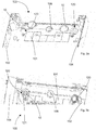
Figur 2 zeigt eine perspektivische Ansicht eines Verteilerschranks nach dem ersten Ausführungsbeispiel; -
Figuren 3a und 3b zeigen einen Ausschnitt einer perspektivischen Ansicht des Verteilerschranks ausFigur 2 ; -
Figuren 4a und4b zeigen einen Verteilerschrank nach dem ersten Ausführungsbeispiel mit einer Montagevorrichtung nach dem ersten Ausführungsbeispiel; -
Figuren 5a und 5b zeigen eine Montagevorrichtung nach einem zweiten Ausführungsbeispiel; -
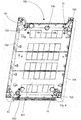
Figur 6 zeigt eine perspektivische Ansicht eines Verteilerschranks nach dem zweiten Ausführungsbeispiel; -
Figuren 7a und 7b zeigen einen Ausschnitt einer perspektivischen Ansicht des Verteilerschranks ausFigur 6 ; -
Figur 8 zeigt einen Verteilerschrank nach dem zweiten Ausführungsbeispiel mit einer Montagevorrichtung nach dem zweiten Ausführungsbeispiel. - Die Ausführungsbeispiele betreffen eine Montagevorrichtung 10 zur Montage eines Verteilerschranks 100 an einer Wand 200. Der Verteilerschrank 100 weist wenigstens eine Aufnahmeöffnung 120 zur Aufnahme der Montagevorrichtung 10 auf.
- Die Montagevorrichtung 10 umfasst einen Hauptabschnitt 20 mit einer Montageöffnung 22 und einen ersten Positionierungsabschnitt 24. Der erste Positionierungsabschnitt ist geeignet, die Montagevorrichtung 10 um eine im Wesentlichen quer zu einer Haupterstreckungsebene der Aufnahmeöffnung 120 verlaufenden Achse drehbar in der Aufnahmeöffnung 120 zu halten. Vorzugsweise verläuft die Achse auch im Wesentlichen orthogonal zur Wand 200, weiterhin vorzugsweise ist der erste Positionierungsabschnitt 24 ein einer ersten Positionierungsposition der Montagevorrichtung 10 in der Aufnahmeöffnung 120 aufgenommen.
- Der erste Positionierungsabschnitt 24 kann nach beiden Ausführungsbeispielen wenigstens einen Vorsprung 25 umfassen, der geeignet ist, an einem Randabschnitt 121 der Aufnahmeöffnung 120 anzuliegen, um ein Herausziehen oder ein Herausfallen der Montagevorrichtung 10 aus der Aufnahmeöffnung 120 parallel zur Achse zu verhindern. Die Montagevorrichtung 10 nach dem Ausführungsbeispiel kann einen ersten Positionierungsabschnitt 24 umfassen, der insgesamt vier Vorsprünge 25 aufweist. Diese Ausgestaltung ist insbesondere in
Figuren 1a ,3b und5a ersichtlich. - Dabei können die Vorsprünge 25 oder der Vorsprung 25 in einer quer zur Achse verlaufenden Richtung verformbar sein, um durch die Aufnahmeöffnung 120 gesteckt werden zu können und um hinter der Aufnahmeöffnung 120 ihre ursprüngliche Form anzunehmen und an den Randabschnitt 121 zur Anlage zu kommen.
- Der erste Positionierungsabschnitt 24 der Montagevorrichtung nach dem zweiten Ausführungsbeispiel kann, wie insbesondere in
Figur 8 zu erkennen ist, eine Auflagefläche 25' umfassen, die an einen zweiten Randabschnitt 121' der Aufnahmeöffnung 120 in der ersten Positionierungsposition anlegbar ist. - Die Montagevorrichtung 10 nach dem ersten Ausführungsbeispiel kann eine Zentrierungsnut 23 umfassen, die geeignet ist, einen Zentrierungskragen 123 der Aufnahmeöffnung 120 aufzunehmen, um die Montagevorrichtung 10 in der Aufnahmeöffnung 120 zu zentrieren und/oder um die Montagevorrichtung 10 in der Aufnahmeöffnung 120 zwischen verschiedenen Dreh- oder Winkelposition zu führen. Vorzugsweise umgibt dabei die Zentrierungsnut 23 den Hauptabschnitt 20 umlaufend. Diese Ausgestaltung ist insbesondere in
Figuren 4a und4b zu erkennen. - Die Zentrierungsnut 23 kann eine in ein Inneres der Nut weisende Verzahnung aufweisen, die geeignet ist, in eine Verzahnung des Zentrierungskragens 123 zu greifen, um die Montagevorrichtung 10 in einer Winkelposition oder Drehposition in der Aufnahmeöffnung 120 zu halten.
- Die Montagevorrichtung 10 nach beiden Ausführungsbeispielen kann, wie beispielsweise in den
Figuren 4a und8 wiedergegeben, die erste Positionierungsposition einnehmen, in welcher der Positionierungsabschnitt 24 derart in der Aufnahmeöffnung 120 aufgenommen ist, dass die Montagevorrichtung 10 um die Achse herum drehbar in der Aufnahmeöffnung gehalten ist. - Die Montagevorrichtung 10 nach dem ersten Ausführungsbeispiel kann ferner einen zweiten Positionierungsabschnitt 26 umfassen, der mit einem Gewinde 27 versehen ist, das geeignet ist, derart in einen Gewindeabschnitt 122 der Aufnahmeöffnung 120 zu greifen, das eine Drehbewegung der Montagevorrichtung 10 um die Achse in eine translatorische Bewegung der Montagevorrichtung 10 parallel zur Achse überführt wird, insbesondere eine Drehbewegung im Uhrzeigersinn oder entgegen des Uhrzeigesinns.
- Die Montagevorrichtung 10 kann, wie beispielsweise in
Figur 4b wiedergegeben, eine zweite Positionierungsposition einnehmen, in welcher der zweite Positionierungsabschnitt in der Aufnahmeöffnung 120 aufgenommen ist, sodass das Gewinde 27 in dem Gewindeabschnitt 122 der Aufnahmeöffnung 120 greift, wodurch eine Drehbewegung der Montagevorrichtung 10 um die Achse in eine translatorische Bewegung der Montagevorrichtung 10 parallel zur Achse überführt wird. Vorzugsweise wird eine Drehbewegung der Montagevorrichtung 10 im oder entgegen des Uhrzeigersinns in eine translatorische Bewegung zur Wand 200 hin überführt. - Vorzugsweise umfasst die Montagevorrichtung 10 nach beiden Ausführungsbeispielen einen Greifabschnitt 28, der den Hauptabschnitt 20 umgibt. Alternativ oder zusätzlich kann die Montagevorrichtung 10, insbesondere der Hauptabschnitt 20 der Montagevorrichtung 10, zur Aufnahme eines Endes eines Werkzeuges einen Schlitz 21 umfassen. Vorzugsweise ist die Montagevorrichtung 10 dadurch geeignet, mittels des Werkzeugs um die Achse gedreht zu werden.
- Weiterhin vorzugsweise umfasst die Montagevorrichtung 10 einen Verschlussabschnitt 30, der an dem Hauptabschnitt 20 und/oder dem Greifabschnitt 28 verrastbar ist, um die Montageöffnung 22 zu verdecken und/oder zu verschließen. Dabei kann der Verschlussabschnitt 30 insbesondere mittels eines flexiblen Stegs 31 mit dem Greifabschnitt 28 und/oder dem Hauptabschnitt 20 verbunden sein, um ein versehentliches Abhandenkommen des Verschlussabschnitts 30 zu verhindern. Diese Ausgestaltung ist insbesondere in den
Figuren 1a bis 1c ,5a und 5b zu erkennen. - Die Montagevorrichtung 10 nach dem ersten Ausführungsbeispiel kann von der ersten Positionierungsposition in die zweite Positionierungsposition überführt werden, indem die Montagevorrichtung 10 entgegen des Uhrzeigersinns gedreht wird, bis das Gewinde 27 in dem Gewindeabschnitt 122 greift.
- Die Montagevorrichtung 10 nach beiden Ausführungsbeispielen kann aus Kunststoff hergestellt sein, beispielsweise mittels eines Spritzgussverfahrens. Die Montagevorrichtung 10 kann eine als Langloch ausgebildete Montageöffnung 22 umfassen. Vorzugsweise ist die Montageöffnung 22 annähernd mittig auf dem Hauptabschnitt 20 angeordnet. Vorzugsweise ist der Hauptabschnitt 20 annähern flächig ausgebildet und erstreckt sich im Wesentlichen in einer Ebene, die orthogonal zur Achse verläuft. Dies ist insbesondere aus den
Figuren 1a bis 1c ,5a und 5b ersichtlich. - Der Greifabschnitt 28, kann, wie insbesondere in den
Figuren 1a bis 1c , zu erkennen ist, kragenförmig ausgebildet sein und den Hauptabschnitt 20 umgeben. Der Greifabschnitt 28 kann mit einzelnen Vertiefungen ausgebildet sein, um ein Greifen des Greifabschnitts 28 durch die Hand eines Installateurs zu erleichtern. - Der Verteilerschrank nach dem Ausführungsbeispiel ist insbesondere in den
Figuren 2 ,3a und 3b wiedergegeben. Der Verteilerschrank 100 umfasst wenigstens eine Aufnahmeöffnung 120 zur Aufnahme der Montagevorrichtung 10. Der Verteilerschrank 100 kann eine Rückwand 101 und sich jeweils orthogonal von der Rückwand 101 erstreckende erste Seitenwand 102 und zweite Seitenwand 104 umfassen. Vorzugsweise ist die wenigstens eine Aufnahmeöffnung 120 in der Rückwand 101 angeordnet. Der Verteilerschrank 100 kann ferner mit einer Vormontageöffnung 106 versehen sein, die vorzugsweise bezüglich der Horizontalen mittig in der Rückwand 101 angeordnet ist. - Wie insbesondere
Figur 3b zeigt, kann die Aufnahmeöffnung 120 von einem Randabschnitt 121 umgeben sein, und zwar vorzugsweise an einer der Wand 200 zugewandten Seite der Rückwand 101. - Die Aufnahmeöffnung 120 kann vorzugsweise innenseitig einen Gewindeabschnitt 122 umfassen, der mit dem Gewinde 27 des zweiten Positionierungsabschnitt 26 zusammenwirkt, um eine Drehbewegung der Montagevorrichtung 10 um die Achse in eine translatorische Bewegung der Montagevorrichtung 10 parallel zur Achse zu überführen.
- Wie insbesondere die
Figuren 4a und4b zu erkennen geben, kann die Aufnahmeöffnung 120 des Verteilerschranks 100 nach dem ersten Ausführungsbeispiel einen Zentrierungskragen 123 umfassen, der in die Zentrierungsnut 23 der Montagevorrichtung 10 aufnehmbar ist, um die Montagevorrichtung 10 in der Aufnahmeöffnung 120 zu zentrieren. Der Zentrierungskragen 123 kann eine Verzahnung umfassen, die in die Verzahnung der Zentrierungsnut 23 eingreift, um die Montagevorrichtung 10 in einer Winkelposition in der Aufnahmeöffnung 120 zu halten.
Die Verzahnung des Zentrierungskragens ist dabei insbesondere inFigur 3b zu erkennen. Die Verzahnung der Zentrierungsnut ist insbesondere inFigur 1a zu erkennen. - Der Verteilerschrank 100 nach beiden Ausführungsbeispielen kann mittels einer Montagevorrichtung 10 und anhand eines Verfahrens zur Montage des Verteilerschranks 100 an der Wand 200 montiert werden. Das Verfahren zur Montage umfasst dabei folgende Verfahrensschritte :
- a) Einbringen einer ersten Bohrung in der Wand 200 ;
- d) Einbringen einer zweiten Bohrung in der Wand 200 ;
- e) Ausrichten der Montageöffnung 22 der Montagevorrichtung 10 mit der ersten Bohrung oder der zweiten Bohrung durch Drehen der Montagevorrichtung 10 in der Aufnahmeöffnung 120 und
- f) Anordnen eines zweiten Befestigungsmittels in der ersten Bohrung und/oder der zweiten Bohrung und der Montageöffnung 22.
- Ausrichten der Montageöffnung 22 in der Montagevorrichtung 10 bedeutet dabei die Montageöffnung 22 fluchtend mit der zweiten Bohrung auszurichten. Das Anordnen eines zweiten Befestigungsmittels in der zweiten Bohrung und der Montageöffnung 22 kann vorzugsweise durch zumindest teilweise Hindurchführen des zweiten Befestigungsmittels durch die Montageöffnung 22 und teilweises Einführen des zweiten Befestigungsmittels in der zweiten Bohrung erfolgen. Vorzugsweise umfasst das erste Befestigungsmittel und/oder das zweite Befestigungsmittel eine Schraube.
- Vorzugsweise kann das Verfahren zur Montage zwischen den Verfahrensschritten a) und d) weitere folgende Verfahrensschritte umfassen
- b) Anordnen eines ersten Befestigungsmittels in der ersten Bohrung und ;
- c) Vormontage des Verteilerschranks 100 durch Aufhängen des Verteilerschranks 100 an dem ersten Befestigungsmittel.
- Vorzugsweise erfolgt in Schritt c) die Vormontage des Verteilerschranks durch Aufhängen des Verteilerschranks mit der Vormontageöffnung 106 an dem ersten Befestigungsmittel.
- Vorzugsweise umfasst das Verfahren zur Montage nach dem Verfahrensschritt f) weiteren folgenden Verfahrensschritt:
- g) Verschließen und/oder Verdecken der Montageöffnung 22 mittels des Verschlussabschnitts 30.
- Markieren einer Stelle für die erste Bohrung und/oder Markieren einer Stelle für die zweite Bohrung.
- In Verfahrensschritt d) kann das Einbringen der zweiten Bohrung durch die Aufnahmeöffnung 120 des Verteilerschranks 100 hindurch erfolgen. Das heißt, das die Bohrung beispielsweise mittels eines Bohrers in die Wand 200 eingebracht werden kann, indem der Bohrer durch die Aufnahmeöffnung 120 des Verteilerschranks 100 hindurchgeführt wird.
- In einer bevorzugten Ausgestaltung des Verfahrens zur Montage kann in Verfahrensschritt e) das Ausrichten der Montagevorrichtung 10 ein Anordnen des ersten Positionierungsabschnitts 24 an der Aufnahmeöffnung 120 und ein Drehen der Montagevorrichtung 10 um die im Wesentlichen quer zu der Haupterstreckungsebene in der Aufnahmeöffnung 120 verlaufenden Achse umfassen, insbesondere ein Drehen im Uhrzeigersinn. Alternativ oder zusätzlich kann in Verfahrensschritt e) das Ausrichten der Montagevorrichtung 10 ein Anordnen des zweiten Positionierungsabschnitts 26 an der Aufnahmeöffnung 120 und ein Drehen der Montagevorrichtung 10 um die im Wesentlichen quer zu der Haupterstreckungsebene der Aufnahmeöffnung 120 verlaufende Achse umfassen.
- In einer bevorzugten Ausgestaltung kann der Verschlussabschnitt 30 mit dem Hauptabschnitt 20 und/oder dem Greifabschnitt 28 mittels eines Stegs 31 verbunden sein.
Claims (14)
- Montagevorrichtung zur Montage eines Verteilerschranks (100) an einer Wand (200), wobei der Verteilerschrank (100) wenigstens eine Aufnahmeöffnung (120) zur Aufnahme der Montagevorrichtung (10) aufweist,wobei die Montagevorrichtung (10) einen Hauptabschnitt (20) mit einer Montageöffnung (22) und einen ersten Positionierungsabschnitt (24) umfasst,dadurch gekennzeichnet, dass der erste Positionierungsabschnitt (24) geeignet ist, die Montagevorrichtung (10) um eine im Wesentlichen quer zu einer Haupterstreckungsebene der Aufnahmeöffnung (120) verlaufene Achse drehbar in der Aufnahmeöffnung (120) zu halten, um zumindest ein zweidimensionales Ausrichten des Verteilerschranks (200) an der Wand zu ermöglichen.
- Montagevorrichtung nach Anspruch 1, dadurch gekennzeichnet, dass der erste Positionierungsabschnitt (24) wenigstens einen Vorsprung (25) umfasst, der geeignet ist, an einem Randabschnitt (121) der Aufnahmeöffnung (120) anzuliegen, um ein Herausziehen der Montagevorrichtung (10) aus der Aufnahmeöffnung (120) parallel zur Achse zu verhindern.
- Montagevorrichtung nach einem der Ansprüche 1 oder 2, gekennzeichnet durch einen zweiten Positionierungsabschnitt (26), der mit einem Gewinde (27) versehen ist, das geeignet ist, derart in einen Gewindeabschnitt (122) der Aufnahmeöffnung (120) zu greifen, dass eine Drehbewegung der Montagevorrichtung (10) um die Achse in eine translatorische Bewegung der Montagevorrichtung (10) parallel zur Achse, insbesondere zur Wand (200) hin, überführt wird, um ein Ausrichten des Verteilerschranks (100) parallel zur Achse an der Wand (200) zu ermöglichen.
- Montagevorrichtung nach einem der Ansprüche 1 bis 3, dadurch gekennzeichnet, dass die Montageöffnung (22) als Langloch ausgebildet ist.
- Montagevorrichtung nach einem der Ansprüche 1 bis 4, gekennzeichnet durch einen Greifabschnitt (28), der den Hauptabschnitt (20) umgibt.
- Montagevorrichtung nach einem der Ansprüche 1 bis 5, gekennzeichnet durch einen Verschlussabschnitt (30), der an dem Hauptabschnitt (20) und/oder dem Greifabschnitt (28) verrastbar ist, um die Montageöffnung (22) zu verdecken und/oder zu verschließen.
- Montagevorrichtung nach einem der Ansprüche 1 bis 6, gekennzeichnet durch eine Zentrierungsnut (23), die geeignet ist, einen Zentrierungskragen (123) der Aufnahmeöffnung (120) aufzunehmen, um die Montagevorrichtung (10) in der Aufnahmeöffnung (120) zu zentrieren, wobei vorzugsweise die Zentrierungsnut (23) den Hauptanschnitt (20) umlaufend umgibt.
- Montagevorrichtung nach Anspruch 7, dadurch gekennzeichnet, dass die Zentrierungsnut (23) eine in ein Inneres der Nut weisende Verzahnung aufweist, die geeignet ist, in eine Verzahnung des Zentrierungskragens (123) zu greifen, um die Montagevorrichtung (10) in einer Winkelposition in der Aufnahmeöffnung (120) zu halten.
- Verteilerschrank zur Montage an einer Wand (200) umfassend wenigstens eine Montagevorrichtung (10) nach einem der Ansprüche 1 bis 8 und wenigstens eine Aufnahmeöffnung (120), in welche die Montagevorrichtung (10) aufgenommen ist.
- Verfahren zur Montage eines Verteilerschranks (100) nach Anspruch 9 an einer Wand (200), umfassend folgende Verfahrensschritte:a) Einbringen einer ersten Bohrung in der Wand (200);d) Einbringen einer zweiten Bohrung in der Wand (200);e) Ausrichten der Montageöffnung (22) der Montagevorrichtung (10) mit der ersten Bohrung und/oder der zweiten Bohrung durch Drehen der Montagevorrichtung (10) in der Aufnahmeöffnung (120);f) Anordnen eines zweiten Befestigungsmittels in der ersten Bohrung und/oder der zweiten Bohrung sowie in der Montageöffnung (22).
- Verfahren zur Montage nach Anspruch 10, dadurch gekennzeichnet, dass das Verfahren zwischen den Verfahrensschritten a) und d) weitere folgenden Verfahrensschritte umfasst:b) Anordnen eines ersten Befestigungsmittels in der ersten Bohrung undc) Vormontage des Verteilerschranks (100) durch Aufhängen des Verteilerschranks (100) an dem ersten Befestigungsmittel.
- Verfahren zur Montage nach einem der Ansprüche 10 oder 11, dadurch gekennzeichnet, dass das Verfahren nach dem Verfahrensschritt f) weiteren folgenden Verfahrensschritt umfasst:g) Verschließen und/oder Verdecken der Montageöffnung mittels des Verschlussabschnitts.
- Verfahren zur Montage nach einem der Ansprüche 10 bis 12, dadurch gekennzeichnet, dass in Verfahrensschritt d) das Einbringen der zweiten Bohrung durch die Aufnahmeöffnung (120) des Verteilerschranks (100) hindurch erfolgt.
- Verfahren zur Montage nach einem der Ansprüche 10 bis 13, dadurch gekennzeichnet, dass in Verfahrensschritt e) das Ausrichten der Montagevorrichtung (10) ein Anordnen des ersten Positionierungsabschnitts (24) an der Aufnahmeöffnung (120) und ein Drehen der Montagevorrichtung (10) um die im Wesentlichen quer zu der Haupterstreckungsebene der Aufnahmeöffnung (120) verlaufenden Achse sowie vorzugsweise ein Anordnen des zweiten Positionierungsabschnitts (26) an der Aufnahmeöffnung (120) und ein Drehen der Montagevorrichtung (10) um die im Wesentlichen quer zu der Haupterstreckungsebene der Aufnahmeöffnung (120) verlaufenden Achse umfasst.
Priority Applications (2)
| Application Number | Priority Date | Filing Date | Title |
|---|---|---|---|
| ES17305106T ES2876923T3 (es) | 2017-01-31 | 2017-01-31 | Dispositivo de montaje para montar un armario distribuidor |
| EP17305106.1A EP3355424B1 (de) | 2017-01-31 | 2017-01-31 | Montagevorrichtung zur montage eines verteilerschranks |
Applications Claiming Priority (1)
| Application Number | Priority Date | Filing Date | Title |
|---|---|---|---|
| EP17305106.1A EP3355424B1 (de) | 2017-01-31 | 2017-01-31 | Montagevorrichtung zur montage eines verteilerschranks |
Publications (2)
| Publication Number | Publication Date |
|---|---|
| EP3355424A1 true EP3355424A1 (de) | 2018-08-01 |
| EP3355424B1 EP3355424B1 (de) | 2021-03-10 |
Family
ID=58018039
Family Applications (1)
| Application Number | Title | Priority Date | Filing Date |
|---|---|---|---|
| EP17305106.1A Active EP3355424B1 (de) | 2017-01-31 | 2017-01-31 | Montagevorrichtung zur montage eines verteilerschranks |
Country Status (2)
| Country | Link |
|---|---|
| EP (1) | EP3355424B1 (de) |
| ES (1) | ES2876923T3 (de) |
Citations (5)
| Publication number | Priority date | Publication date | Assignee | Title |
|---|---|---|---|---|
| GB785896A (en) * | 1955-07-04 | 1957-11-06 | Midland Electric Mfg Co Ltd | Corner fittings for use in the construction of sheet metal boxes |
| DE1941418U (de) * | 1964-07-25 | 1966-06-30 | Siemens Elektrogeraete Gmbh | Montagenippel. |
| JPS54156957A (en) * | 1978-05-31 | 1979-12-11 | Matsushita Electric Works Ltd | Fitting fine adjustment mechanism |
| EP1149545A1 (de) * | 2000-04-27 | 2001-10-31 | Schneider Electric Industries SA | Vorrichtung zur Mauerbefestigung eines Kastens |
| DE202009002003U1 (de) * | 2008-11-27 | 2010-04-08 | Hettich-Heinze Gmbh & Co. Kg | Beschlag und Wandschrank |
-
2017
- 2017-01-31 EP EP17305106.1A patent/EP3355424B1/de active Active
- 2017-01-31 ES ES17305106T patent/ES2876923T3/es active Active
Patent Citations (5)
| Publication number | Priority date | Publication date | Assignee | Title |
|---|---|---|---|---|
| GB785896A (en) * | 1955-07-04 | 1957-11-06 | Midland Electric Mfg Co Ltd | Corner fittings for use in the construction of sheet metal boxes |
| DE1941418U (de) * | 1964-07-25 | 1966-06-30 | Siemens Elektrogeraete Gmbh | Montagenippel. |
| JPS54156957A (en) * | 1978-05-31 | 1979-12-11 | Matsushita Electric Works Ltd | Fitting fine adjustment mechanism |
| EP1149545A1 (de) * | 2000-04-27 | 2001-10-31 | Schneider Electric Industries SA | Vorrichtung zur Mauerbefestigung eines Kastens |
| DE202009002003U1 (de) * | 2008-11-27 | 2010-04-08 | Hettich-Heinze Gmbh & Co. Kg | Beschlag und Wandschrank |
Also Published As
| Publication number | Publication date |
|---|---|
| ES2876923T3 (es) | 2021-11-15 |
| EP3355424B1 (de) | 2021-03-10 |
Similar Documents
| Publication | Publication Date | Title |
|---|---|---|
| DE102008017423B4 (de) | Überspannungsschutzgerät | |
| DE102014109351B3 (de) | Steckverbinder mit Schutzleiterbrücke | |
| DE102008041125A1 (de) | Halterung für ein Kraftfahrzeug-Anbauteil sowie Vorrichtung zum Halten eines Kraftfahrzeug-Anbauteils | |
| CH710388A2 (de) | Rohreinführung für eine Unterputzdose. | |
| DE102014109423A1 (de) | Gehäuse und Anordnung | |
| EP3114361A1 (de) | Befestigungselement für einen stromsensor | |
| DE102018127230A1 (de) | Wanddurchführungseinrichtung | |
| EP3513633A1 (de) | Gehäuse für ein steuergerät und abdeckhaube für das gehäuse | |
| DE102020201108A1 (de) | Wandhalterung | |
| DE102024100111A1 (de) | Zähler- und Verteilerschrank | |
| EP3355424B1 (de) | Montagevorrichtung zur montage eines verteilerschranks | |
| DE202007002907U1 (de) | Verbindungsklemme für elektrische Leiter | |
| EP2263292B1 (de) | Zugentlastungsvorrichtung | |
| DE202014100373U1 (de) | Installationsdose | |
| DE102016115488B3 (de) | Anbaugehäuse | |
| DE102021127587B3 (de) | Steckdosenleiste | |
| DE102006029807B4 (de) | Befestigungsvorrichtung mit Schwenkbasis | |
| DE102021004837B4 (de) | Aufnahme- und Festlegevorrichtung, System, Schaltschrank und Anschlusssystem | |
| DE102006017983B4 (de) | Elektrische Steckverbindung | |
| DE102016119999B3 (de) | Bausatz für einen Kabeldeckenauslass | |
| DE102024134943A1 (de) | Befestigungsvorrichtung und damit gebildete Einrichtung | |
| DE29711066U1 (de) | Vorrichtung zum Verbinden zweier Teile | |
| DE19959882A1 (de) | Befestigungsvorrichtung | |
| EP2770594B1 (de) | Verfahren zur Installation von Elektroleitungen sowie zugehörige Vorrichtung | |
| DE102023110948A1 (de) | Vorrichtung zur verankerung eines installationskastens, installationskasten und verfahren zur verankerung eines installationskastens in einer hohlwand |
Legal Events
| Date | Code | Title | Description |
|---|---|---|---|
| PUAI | Public reference made under article 153(3) epc to a published international application that has entered the european phase |
Free format text: ORIGINAL CODE: 0009012 |
|
| STAA | Information on the status of an ep patent application or granted ep patent |
Free format text: STATUS: THE APPLICATION HAS BEEN PUBLISHED |
|
| AK | Designated contracting states |
Kind code of ref document: A1 Designated state(s): AL AT BE BG CH CY CZ DE DK EE ES FI FR GB GR HR HU IE IS IT LI LT LU LV MC MK MT NL NO PL PT RO RS SE SI SK SM TR |
|
| AX | Request for extension of the european patent |
Extension state: BA ME |
|
| STAA | Information on the status of an ep patent application or granted ep patent |
Free format text: STATUS: REQUEST FOR EXAMINATION WAS MADE |
|
| 17P | Request for examination filed |
Effective date: 20190124 |
|
| RBV | Designated contracting states (corrected) |
Designated state(s): AL AT BE BG CH CY CZ DE DK EE ES FI FR GB GR HR HU IE IS IT LI LT LU LV MC MK MT NL NO PL PT RO RS SE SI SK SM TR |
|
| STAA | Information on the status of an ep patent application or granted ep patent |
Free format text: STATUS: EXAMINATION IS IN PROGRESS |
|
| 17Q | First examination report despatched |
Effective date: 20200318 |
|
| GRAP | Despatch of communication of intention to grant a patent |
Free format text: ORIGINAL CODE: EPIDOSNIGR1 |
|
| STAA | Information on the status of an ep patent application or granted ep patent |
Free format text: STATUS: GRANT OF PATENT IS INTENDED |
|
| INTG | Intention to grant announced |
Effective date: 20200817 |
|
| GRAS | Grant fee paid |
Free format text: ORIGINAL CODE: EPIDOSNIGR3 |
|
| GRAA | (expected) grant |
Free format text: ORIGINAL CODE: 0009210 |
|
| STAA | Information on the status of an ep patent application or granted ep patent |
Free format text: STATUS: THE PATENT HAS BEEN GRANTED |
|
| AK | Designated contracting states |
Kind code of ref document: B1 Designated state(s): AL AT BE BG CH CY CZ DE DK EE ES FI FR GB GR HR HU IE IS IT LI LT LU LV MC MK MT NL NO PL PT RO RS SE SI SK SM TR |
|
| REG | Reference to a national code |
Ref country code: GB Ref legal event code: FG4D Free format text: NOT ENGLISH |
|
| REG | Reference to a national code |
Ref country code: CH Ref legal event code: EP Ref country code: AT Ref legal event code: REF Ref document number: 1370867 Country of ref document: AT Kind code of ref document: T Effective date: 20210315 |
|
| REG | Reference to a national code |
Ref country code: DE Ref legal event code: R096 Ref document number: 502017009644 Country of ref document: DE |
|
| REG | Reference to a national code |
Ref country code: IE Ref legal event code: FG4D Free format text: LANGUAGE OF EP DOCUMENT: GERMAN |
|
| REG | Reference to a national code |
Ref country code: NL Ref legal event code: FP |
|
| REG | Reference to a national code |
Ref country code: LT Ref legal event code: MG9D |
|
| PG25 | Lapsed in a contracting state [announced via postgrant information from national office to epo] |
Ref country code: LT Free format text: LAPSE BECAUSE OF FAILURE TO SUBMIT A TRANSLATION OF THE DESCRIPTION OR TO PAY THE FEE WITHIN THE PRESCRIBED TIME-LIMIT Effective date: 20210310 Ref country code: BG Free format text: LAPSE BECAUSE OF FAILURE TO SUBMIT A TRANSLATION OF THE DESCRIPTION OR TO PAY THE FEE WITHIN THE PRESCRIBED TIME-LIMIT Effective date: 20210610 Ref country code: HR Free format text: LAPSE BECAUSE OF FAILURE TO SUBMIT A TRANSLATION OF THE DESCRIPTION OR TO PAY THE FEE WITHIN THE PRESCRIBED TIME-LIMIT Effective date: 20210310 Ref country code: GR Free format text: LAPSE BECAUSE OF FAILURE TO SUBMIT A TRANSLATION OF THE DESCRIPTION OR TO PAY THE FEE WITHIN THE PRESCRIBED TIME-LIMIT Effective date: 20210611 Ref country code: FI Free format text: LAPSE BECAUSE OF FAILURE TO SUBMIT A TRANSLATION OF THE DESCRIPTION OR TO PAY THE FEE WITHIN THE PRESCRIBED TIME-LIMIT Effective date: 20210310 Ref country code: NO Free format text: LAPSE BECAUSE OF FAILURE TO SUBMIT A TRANSLATION OF THE DESCRIPTION OR TO PAY THE FEE WITHIN THE PRESCRIBED TIME-LIMIT Effective date: 20210610 |
|
| PG25 | Lapsed in a contracting state [announced via postgrant information from national office to epo] |
Ref country code: RS Free format text: LAPSE BECAUSE OF FAILURE TO SUBMIT A TRANSLATION OF THE DESCRIPTION OR TO PAY THE FEE WITHIN THE PRESCRIBED TIME-LIMIT Effective date: 20210310 Ref country code: LV Free format text: LAPSE BECAUSE OF FAILURE TO SUBMIT A TRANSLATION OF THE DESCRIPTION OR TO PAY THE FEE WITHIN THE PRESCRIBED TIME-LIMIT Effective date: 20210310 Ref country code: SE Free format text: LAPSE BECAUSE OF FAILURE TO SUBMIT A TRANSLATION OF THE DESCRIPTION OR TO PAY THE FEE WITHIN THE PRESCRIBED TIME-LIMIT Effective date: 20210310 |
|
| PG25 | Lapsed in a contracting state [announced via postgrant information from national office to epo] |
Ref country code: EE Free format text: LAPSE BECAUSE OF FAILURE TO SUBMIT A TRANSLATION OF THE DESCRIPTION OR TO PAY THE FEE WITHIN THE PRESCRIBED TIME-LIMIT Effective date: 20210310 Ref country code: CZ Free format text: LAPSE BECAUSE OF FAILURE TO SUBMIT A TRANSLATION OF THE DESCRIPTION OR TO PAY THE FEE WITHIN THE PRESCRIBED TIME-LIMIT Effective date: 20210310 Ref country code: SM Free format text: LAPSE BECAUSE OF FAILURE TO SUBMIT A TRANSLATION OF THE DESCRIPTION OR TO PAY THE FEE WITHIN THE PRESCRIBED TIME-LIMIT Effective date: 20210310 |
|
| REG | Reference to a national code |
Ref country code: ES Ref legal event code: FG2A Ref document number: 2876923 Country of ref document: ES Kind code of ref document: T3 Effective date: 20211115 |
|
| PG25 | Lapsed in a contracting state [announced via postgrant information from national office to epo] |
Ref country code: IS Free format text: LAPSE BECAUSE OF FAILURE TO SUBMIT A TRANSLATION OF THE DESCRIPTION OR TO PAY THE FEE WITHIN THE PRESCRIBED TIME-LIMIT Effective date: 20210710 Ref country code: SK Free format text: LAPSE BECAUSE OF FAILURE TO SUBMIT A TRANSLATION OF THE DESCRIPTION OR TO PAY THE FEE WITHIN THE PRESCRIBED TIME-LIMIT Effective date: 20210310 Ref country code: RO Free format text: LAPSE BECAUSE OF FAILURE TO SUBMIT A TRANSLATION OF THE DESCRIPTION OR TO PAY THE FEE WITHIN THE PRESCRIBED TIME-LIMIT Effective date: 20210310 Ref country code: PL Free format text: LAPSE BECAUSE OF FAILURE TO SUBMIT A TRANSLATION OF THE DESCRIPTION OR TO PAY THE FEE WITHIN THE PRESCRIBED TIME-LIMIT Effective date: 20210310 Ref country code: PT Free format text: LAPSE BECAUSE OF FAILURE TO SUBMIT A TRANSLATION OF THE DESCRIPTION OR TO PAY THE FEE WITHIN THE PRESCRIBED TIME-LIMIT Effective date: 20210712 |
|
| REG | Reference to a national code |
Ref country code: DE Ref legal event code: R097 Ref document number: 502017009644 Country of ref document: DE |
|
| PLBE | No opposition filed within time limit |
Free format text: ORIGINAL CODE: 0009261 |
|
| STAA | Information on the status of an ep patent application or granted ep patent |
Free format text: STATUS: NO OPPOSITION FILED WITHIN TIME LIMIT |
|
| PG25 | Lapsed in a contracting state [announced via postgrant information from national office to epo] |
Ref country code: DK Free format text: LAPSE BECAUSE OF FAILURE TO SUBMIT A TRANSLATION OF THE DESCRIPTION OR TO PAY THE FEE WITHIN THE PRESCRIBED TIME-LIMIT Effective date: 20210310 Ref country code: AL Free format text: LAPSE BECAUSE OF FAILURE TO SUBMIT A TRANSLATION OF THE DESCRIPTION OR TO PAY THE FEE WITHIN THE PRESCRIBED TIME-LIMIT Effective date: 20210310 |
|
| 26N | No opposition filed |
Effective date: 20211213 |
|
| PG25 | Lapsed in a contracting state [announced via postgrant information from national office to epo] |
Ref country code: SI Free format text: LAPSE BECAUSE OF FAILURE TO SUBMIT A TRANSLATION OF THE DESCRIPTION OR TO PAY THE FEE WITHIN THE PRESCRIBED TIME-LIMIT Effective date: 20210310 |
|
| PG25 | Lapsed in a contracting state [announced via postgrant information from national office to epo] |
Ref country code: IS Free format text: LAPSE BECAUSE OF FAILURE TO SUBMIT A TRANSLATION OF THE DESCRIPTION OR TO PAY THE FEE WITHIN THE PRESCRIBED TIME-LIMIT Effective date: 20210710 |
|
| PGFP | Annual fee paid to national office [announced via postgrant information from national office to epo] |
Ref country code: DE Payment date: 20220628 Year of fee payment: 6 |
|
| PG25 | Lapsed in a contracting state [announced via postgrant information from national office to epo] |
Ref country code: MC Free format text: LAPSE BECAUSE OF FAILURE TO SUBMIT A TRANSLATION OF THE DESCRIPTION OR TO PAY THE FEE WITHIN THE PRESCRIBED TIME-LIMIT Effective date: 20210310 |
|
| REG | Reference to a national code |
Ref country code: CH Ref legal event code: PL |
|
| GBPC | Gb: european patent ceased through non-payment of renewal fee |
Effective date: 20220131 |
|
| PG25 | Lapsed in a contracting state [announced via postgrant information from national office to epo] |
Ref country code: LU Free format text: LAPSE BECAUSE OF NON-PAYMENT OF DUE FEES Effective date: 20220131 Ref country code: GB Free format text: LAPSE BECAUSE OF NON-PAYMENT OF DUE FEES Effective date: 20220131 |
|
| PG25 | Lapsed in a contracting state [announced via postgrant information from national office to epo] |
Ref country code: LI Free format text: LAPSE BECAUSE OF NON-PAYMENT OF DUE FEES Effective date: 20220131 Ref country code: CH Free format text: LAPSE BECAUSE OF NON-PAYMENT OF DUE FEES Effective date: 20220131 |
|
| PG25 | Lapsed in a contracting state [announced via postgrant information from national office to epo] |
Ref country code: IE Free format text: LAPSE BECAUSE OF NON-PAYMENT OF DUE FEES Effective date: 20220131 |
|
| REG | Reference to a national code |
Ref country code: AT Ref legal event code: MM01 Ref document number: 1370867 Country of ref document: AT Kind code of ref document: T Effective date: 20220131 |
|
| PG25 | Lapsed in a contracting state [announced via postgrant information from national office to epo] |
Ref country code: AT Free format text: LAPSE BECAUSE OF NON-PAYMENT OF DUE FEES Effective date: 20220131 |
|
| P01 | Opt-out of the competence of the unified patent court (upc) registered |
Effective date: 20230606 |
|
| REG | Reference to a national code |
Ref country code: DE Ref legal event code: R119 Ref document number: 502017009644 Country of ref document: DE |
|
| PG25 | Lapsed in a contracting state [announced via postgrant information from national office to epo] |
Ref country code: DE Free format text: LAPSE BECAUSE OF NON-PAYMENT OF DUE FEES Effective date: 20230801 |
|
| PG25 | Lapsed in a contracting state [announced via postgrant information from national office to epo] |
Ref country code: HU Free format text: LAPSE BECAUSE OF FAILURE TO SUBMIT A TRANSLATION OF THE DESCRIPTION OR TO PAY THE FEE WITHIN THE PRESCRIBED TIME-LIMIT; INVALID AB INITIO Effective date: 20170131 |
|
| PG25 | Lapsed in a contracting state [announced via postgrant information from national office to epo] |
Ref country code: MK Free format text: LAPSE BECAUSE OF FAILURE TO SUBMIT A TRANSLATION OF THE DESCRIPTION OR TO PAY THE FEE WITHIN THE PRESCRIBED TIME-LIMIT Effective date: 20210310 Ref country code: CY Free format text: LAPSE BECAUSE OF FAILURE TO SUBMIT A TRANSLATION OF THE DESCRIPTION OR TO PAY THE FEE WITHIN THE PRESCRIBED TIME-LIMIT Effective date: 20210310 |
|
| PG25 | Lapsed in a contracting state [announced via postgrant information from national office to epo] |
Ref country code: TR Free format text: LAPSE BECAUSE OF FAILURE TO SUBMIT A TRANSLATION OF THE DESCRIPTION OR TO PAY THE FEE WITHIN THE PRESCRIBED TIME-LIMIT Effective date: 20210310 |
|
| PG25 | Lapsed in a contracting state [announced via postgrant information from national office to epo] |
Ref country code: MT Free format text: LAPSE BECAUSE OF FAILURE TO SUBMIT A TRANSLATION OF THE DESCRIPTION OR TO PAY THE FEE WITHIN THE PRESCRIBED TIME-LIMIT Effective date: 20210310 |
|
| PGFP | Annual fee paid to national office [announced via postgrant information from national office to epo] |
Ref country code: NL Payment date: 20260126 Year of fee payment: 10 |
|
| PGFP | Annual fee paid to national office [announced via postgrant information from national office to epo] |
Ref country code: ES Payment date: 20260202 Year of fee payment: 10 |
|
| PGFP | Annual fee paid to national office [announced via postgrant information from national office to epo] |
Ref country code: IT Payment date: 20260121 Year of fee payment: 10 Ref country code: BE Payment date: 20260127 Year of fee payment: 10 |
|
| PGFP | Annual fee paid to national office [announced via postgrant information from national office to epo] |
Ref country code: FR Payment date: 20260126 Year of fee payment: 10 |