EP3354615A1 - Driving system for driving a conveyer band of a conveyer apparatus - Google Patents
Driving system for driving a conveyer band of a conveyer apparatus Download PDFInfo
- Publication number
- EP3354615A1 EP3354615A1 EP17380003.8A EP17380003A EP3354615A1 EP 3354615 A1 EP3354615 A1 EP 3354615A1 EP 17380003 A EP17380003 A EP 17380003A EP 3354615 A1 EP3354615 A1 EP 3354615A1
- Authority
- EP
- European Patent Office
- Prior art keywords
- shaft
- pins
- driving system
- gear
- motor
- Prior art date
- Legal status (The legal status is an assumption and is not a legal conclusion. Google has not performed a legal analysis and makes no representation as to the accuracy of the status listed.)
- Withdrawn
Links
- 230000033001 locomotion Effects 0.000 claims abstract description 47
- 230000001360 synchronised effect Effects 0.000 claims description 7
- 230000001419 dependent effect Effects 0.000 claims 3
- 230000000694 effects Effects 0.000 description 17
- 230000004907 flux Effects 0.000 description 11
- 230000008901 benefit Effects 0.000 description 6
- 230000005540 biological transmission Effects 0.000 description 4
- 230000006870 function Effects 0.000 description 3
- 238000009434 installation Methods 0.000 description 3
- 235000012771 pancakes Nutrition 0.000 description 3
- 230000006378 damage Effects 0.000 description 2
- 238000012423 maintenance Methods 0.000 description 2
- 230000007613 environmental effect Effects 0.000 description 1
- 230000003993 interaction Effects 0.000 description 1
- 230000009467 reduction Effects 0.000 description 1
- 238000005096 rolling process Methods 0.000 description 1
- 235000013580 sausages Nutrition 0.000 description 1
- 230000035807 sensation Effects 0.000 description 1
Images





Classifications
-
- B—PERFORMING OPERATIONS; TRANSPORTING
- B66—HOISTING; LIFTING; HAULING
- B66B—ELEVATORS; ESCALATORS OR MOVING WALKWAYS
- B66B23/00—Component parts of escalators or moving walkways
- B66B23/02—Driving gear
- B66B23/026—Driving gear with a drive or carrying sprocket wheel located at end portions
-
- B—PERFORMING OPERATIONS; TRANSPORTING
- B66—HOISTING; LIFTING; HAULING
- B66B—ELEVATORS; ESCALATORS OR MOVING WALKWAYS
- B66B23/00—Component parts of escalators or moving walkways
- B66B23/02—Driving gear
- B66B23/022—Driving gear with polygon effect reduction means
Definitions
- the present invention relates to a driving system for driving a conveyer band of a conveyer apparatus and a corresponding conveyer apparatus comprising a first rotatable shaft coupled with at least one sprocket, wherein the at least one sprocket is adapted to be coupled with at least one chain of the conveyer band, and comprising a second rotatable shaft coupled with a motor, wherein the motor is adapted to set the second rotatable shaft into a rotary motion.
- a conveyor band (step band or pallet band) is driven by means of a motor.
- the conveyor band is usually connected with chains, comprising a plurality of chain links connected by corresponding connection means, e.g. pins, plates, rollers, etc.
- a main shaft of the conveyer apparatus usually located in one end of the apparatus, is connected with at least one sprocket. This sprocket has a number of teeth on its circumference, which engage the connection means of the corresponding chain.
- the motor can convert electric energy into mechanical energy, by means of which the main shaft can be set into rotation, thus moving the conveyor band.
- a conveyer apparatus of this kind is e.g. described in EP 1 680 348 A1 or in US 5 950 797 A .
- a disadvantage of this kind of conveyor apparatus is that vibrations due to the so called polygon effect are generated, as e.g. described in EP2 033 928 A1 . Vibrations of that kind arise due to interaction of the chains with the sprockets:
- a chain comprises several of discrete chain links connected with each other by connection means, such as pins, plates, rollers, etc. The engagement of these connection means with the teeth of the sprocket causes vibration and fluctuation of the chain, which is referred to polygon effect.
- vibrations cause undesirable friction between the chain and the sprocket, thereby reducing the service life time of these components.
- the ride experience of a user of the conveyor apparatus can be negatively affected by this polygon effect.
- a user can feel these vibrations, which can result in an unpleasant sensation.
- noise is generated by the vibrations, which can be perceived as annoying by users or by people in the vicinity of the conveyor apparatus.
- the invention relates to a driving system for driving a conveyer band of a conveyer apparatus and a corresponding conveyer apparatus with the features of the independent claims. Further advantages and embodiments of the invention will become apparent from the description and the appended figures.
- the conveyer apparatus can especially be an escalator or a moving walkway.
- the conveyer band is particularly a step band.
- the conveyer band is especially a pallet band.
- a first rotatable shaft is coupled with at least one sprocket.
- the at least one sprocket is adapted to be coupled with at least one chain of the conveyer band.
- the conveyer band comprises two chains, one on each side of the conveyer apparatus.
- the first shaft especially comprises two sprockets, one for each chain.
- the first shaft is particularly a main shaft or chain wheel drive shaft of the conveyer apparatus.
- the first shaft can especially be directly connected with the sprockets by means of a rotationally fixed connection.
- Each sprocket especially comprises a profiled wheel with a number of teeth for meshing and engaging connection means of the corresponding chain. These connection means connect the corresponding chain links with each other. Thus, the chain and the conveyor band are moved as the sprocket rotates.
- the conveyer apparatus comprises more than one chain and thus more than one sprocket
- these sprockets can e.g. also be connected by other means than the first shaft, e.g. by another shaft of by other power transmission elements adapted to keep the motion of the chains synchronised.
- a motor or electric machine is provided for driving the conveyor band. Electric energy is converted into mechanical energy by the motor. This mechanical energy is used to drive the conveyor band.
- a second rotatable shaft is coupled with the motor.
- the motor is adapted to set the second rotatable shaft into a rotary motion.
- the second rotatable shaft can be coupled directly to the motor.
- the second shaft can be constructed as a motor shaft. It is also possible that the second shaft is coupled to the motor shaft via other elements.
- the driving system comprises a gearbox, which is adapted to transfer the rotary motion of the second shaft into a rotary motion of the first shaft.
- a gearbox which is adapted to transfer the rotary motion of the second shaft into a rotary motion of the first shaft.
- at least one stage of the gearbox is provided as a cycloidal drive.
- the at least one sprocket is set into rotatory movement and hence the conveyor band is moved.
- the invention is based on the realisation that the use of a cycloidal drive in a conveyor apparatus yields distinct advantages. Particularly, efficiency of the drive system can be increased and environmental impact can be reduced. Costs and effort for installation, operation, and maintenance of the conveyor apparatus can be reduced.
- the intensity of the polygon effect particularly depends on the speed of the chain.
- the speed of the chain can not be controlled precisely enough to reduce vibrations due to the polygon effect.
- the motor does not enable a very accurate control of the chain speed.
- the speed of the chain can expediently be controlled in order to reduce or prevent vibrations due to the polygon effect.
- due to the specific design of the cycloid drive a variable speed pattern of the rotation of the first shaft can be enabled.
- the cycloid drive is especially specifically designed to enable a specific speed pattern of the first shaft, by means of which a specific speed pattern of the chain, particularly a constant speed chain, can be achieved.
- the riding experience of a user can be improved and noise pollution can be reduced.
- no undesirable friction between the chain and the sprocket is caused, which can arise due to the polygon effect.
- the service life time of these components can be increased and maintenance costs can be reduced.
- the cycloidal drive has minimal space requirements, especially compared with other kinds of gearboxes.
- a relatively high gear ratio can be achieved with minimal space requirements.
- dimensions of the conveyor apparatus can be reduced or the saved space can be used for other elements or purposes. Logistics and installation of the conveyor apparatus can hence be simplified.
- a motor can be connected to a gearbox, which is connected via a chain, e.g. a duplex or triplex chain, to a main shaft, on which sprockets are arranged.
- a chain e.g. a duplex or triplex chain
- main shaft on which sprockets are arranged.
- sprockets there is the danger of e.g. breakage of the duplex or triplex chain or loosening of supporting screws of the motor and the gearbox.
- the steps or pallets of the corresponding conveyor band may move without any control, possibly resulting in injuries of passengers or damage of transported goods.
- a first gear is provided, which is in rotationally fixed connection with the first shaft.
- a second gear is provided, which is in rotationally fixed connection with an element of the cycloidal drive.
- the first gear and the second gear are coupled with each other.
- these two gears particularly form a gearbox train, which is preferably provided as a second stage of the gearbox.
- the rotary motion of the second shaft is transferred via the cycloidal drive into a rotary motion of the second gear.
- this rotary motion of the second gear is transferred into a rotary motion of the first gear and hence into the rotary motion of the first shaft.
- the cycloidal drive comprises at least one eccentric disc and at least one cycloidal disc.
- the at least one cycloidal disc has an external surface with a number of lobes.
- the at least one eccentric disc is preferably set into rotation by the second shaft.
- the at least one eccentric disc is adapted to set the at least one cycloidal disc in motion, particularly in an eccentric, cycloidal motion.
- the at least one eccentric disc is arranged in the centre of the at least one cycloidal disc.
- the at least one cycloidal disc and the at least one eccentric disc are especially coupled with each other via a bearing, e.g. a rolling bearing.
- the second shaft is advantageously in a rotationally fixed connection with the at least one eccentric disc.
- the second shaft and the eccentric disc(s) are preferably connected directly with each other.
- the second shaft is connected with the at least one eccentric disc preferably via a planetary stage of the gearbox.
- the second shaft can particularly set a pinion in rotary motion, which engages at least one sprocket of the corresponding planetary gear. This at least one sprocket is in particularly in rotationally fixed connection with the at least one eccentric disc.
- the cycloidal drive comprises a first pin element and a second pin element.
- the first pin element or ring gear element is arranged preferably coaxial to the second shaft and comprises a number of first pins. These first pins are especially arranged on a circumference or circle coaxial to the second shaft.
- the at least one cycloidal disc is arranged inside this circumference or circle.
- the number of first pins is preferably larger than the number of lobes of the at least one cycloidal disc.
- the first pins roll on the external surface of the at least one cycloidal disc.
- the first pins can be provided as rotating and/or low friction pins.
- the second pin element is preferably also arranged coaxially to the second shaft and comprises a number of second pins.
- the at least one cycloidal disc comprises a number of holes equal to or larger than the number of second pins.
- the number of holes and second pins can especially be identical. Particularly, there are at most five more holes than second pins.
- the second pins are adapted to engage the holes in the at least one cycloidal disc.
- the second pins can be provided as rotating and/or low friction pins. It is also possible, that the second pin element is connected to sprocket shafts of the aforementioned planetary stage of the gearbox.
- the second pin element can e.g. also be constructed as a shaft.
- the second pin element is fixed, e.g. to a housing of the motor or of the gear box.
- the first pin element is in this case preferably pivotable.
- a corresponding bearing for the first pin element can e.g. be provided in a housing of the gearbox.
- the rotary motion of the second shaft is thus especially transferred into a rotary motion of the first pin element.
- the gearbox is in this case preferably adapted to transfer the rotary motion of the second shaft into a rotary motion of the first pin element and to transfer this latter motion into the rotary motion of the first shaft.
- the first pin element is preferably in rotationally fixed connection with the second gear or the chain sprocket.
- rotary motion of the first pin element is transferred into rotary motion of the second gear or of the chain sprocket.
- the first pin element is fixed and the second pin element is pivotable.
- the first pin element can in this case be fixed to the conveyor apparatus, e.g. to the housing of the motor or of the gear box.
- a corresponding bearing for the second pin element can be provided in the gearbox housing.
- the gearbox is in this case preferably adapted to transfer the rotary motion of the second shaft into a rotary motion of the second pin element and to transfer this latter motion into the rotary motion of the first shaft.
- the second pin element is in this case advantageously in rotationally fixed connection with the second gear or the chain sprocket.
- the rotary motion of the second pin element is transferred into rotary motion of the second gear or the chain sprocket.
- the number of first pins is equal to a number of teeth of the at least one sprocket or equal to an integer multiple of this number of teeth.
- the number of lobes is preferably equal to the number of first pins minus a ratio between the number of first pins and the number of teeth of the at least one sprocket.
- the shape of the external surface of the at least one cycloidal disc is thus specifically modified to achieve a specific speed pattern of the first shaft in order to achieve a constant speed of the conveyor band and thus to minimise or even prevent vibrations due to the polygon effect. This configuration is especially advantageous if a gear ratio of the first and the second gear is 1:1 or if a first and a second gear are provided.
- this configuration is particularly advantageous for sprockets with less than 16 teeth. For example, if the number of teeth is 10 and the number of first pins is 10, the number of lobes will especially be 9. If, for instance, the sprockets have 10 teeth and if there are 20 first pins, the cycloidal disc(s) will especially have 18 lobes.
- the number of first pins is equal to a number of teeth of the at least one sprocket multiplied by a factor y or equal to an integer multiple of the number of teeth of the at least one sprocket multiplied by the factor y.
- This factor y preferably corresponds to a gear ratio of y:1 of the number of teeth of the second gear and the number of teeth of the first gear.
- the number of lobes is preferably equal to the number of first pins minus a ratio between the number of first pins and the number of teeth of the at least one sprocket multiplied by the factor y.
- This configuration is also particularly advantageous for sprockets with less than 16 teeth. Also by this specific shape of the external surface of the cycloidal disc(s) a specific speed pattern of the first shaft and a constant speed of the conveyor band can especially be achieved in order to minimise or prevent vibrations due to the polygon effect.
- This configuration also yields the possibility to minimise or prevent vibrations due to the polygon effect.
- the second rotatable shaft is coupled to a shaft of the motor via a second gearbox, e.g. via a gear train with one gear connected with the motor shaft and one gear connected with the second shaft.
- a second gearbox e.g. via a gear train with one gear connected with the motor shaft and one gear connected with the second shaft.
- the motor can be of an expedient design.
- the motor is a permanent magnet synchronous motor (PMSM). This motor type presents advantages in torque density and efficiency.
- the motor is a PMSM with an axial flux or with radial flux with a diameter larger than the length (so called "pancake" type PMSM).
- PMSM axial flux motor
- the magnetic force (through the air gap) is along the same plane as the motor shaft, i.e. along the length of the motor.
- the motor shaft or an output shaft coupled with the motor shaft is particularly arranged parallel with the first shaft of the conveyor apparatus.
- the motor can preferably be a PMSM with radial flux or with an axial flux with several discs (so called "sausage" type PMSM).
- PMSM radial flux motor of this kind
- the magnetic force is perpendicular to the length of the motor or motor shaft.
- This PMSM with radial flux particularly has a longer, skinnier design than the "pancake" type PMSM.
- the motor and/or the gearbox in between the two chains of the conveyor band.
- This design can be appropriate for escalators.
- the motor and/or the gearbox can also be arranged outside of the area between these two chains and especially outside a truss of the conveyor apparatus. This design can be advantageous for moving walkways. It is also possible to e.g. arrange the motor in between the two chains and the gearbox on the outside of the truss.
- the driving system may comprise other elements, e.g. a brake and/or a handrail drive.
- a brake can be provided and can interact e.g. with the motor, the first shaft, the second shaft and/or other elements.
- the brake can have a holding function in order to stop a motion of the conveyor band.
- the brake can have an emergency braking function.
- a handrail drive can be provided to set one or several handrails of the conveyor apparatus in motion.
- the handrail drive can e.g. also be driven by the motor and can be coupled to the motor by means of power transmission, e.g. belts or chains.
- the handrail drive can also be driven by means of a mechanical connection with the at least one chain of the conveyor apparatus. It is also possible that a second motor for driving the handrails is provided, which is especially synchronised with the motor of the driving system.
- the conveyor apparatus especially comprises one or several of the following elements: a guiding system for the conveyor band and/or the chains; a supporting structure, e.g. a truss; plates provided to transfer passengers from the conveyor band to the surrounding area and vice versa; balustrades provided on both sides of the conveyor apparatus; handrails provided on both sides of the conveyor apparatus moving substantially at the same speed of conveyor band; control and/or safety systems.
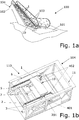
- FIGS 1a, 1b schematically show a preferred embodiment of a conveyor apparatus 100 according to the invention.
- the conveyor apparatus 100 is an escalator.
- FIG. 1a schematically shows the escalator 100 in a perspective view, which is provided between a first, lower floor 101 and a second, higher floor 102.
- the escalator 100 comprises a conveyor band 10, which is provided as a step band comprising a plurality of steps 1. Furthermore, the escalator 100 comprises two handrails 103, one handrail on each side of the conveyor band 10.
- An upper head 104 of the escalator 100 is shown in Figure 1b in a perspective view.
- a preferred embodiment of a driving system 110 according to the invention for driving the conveyer band 10 of the conveyer apparatus 100 is provided in the upper head 104.
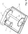
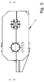
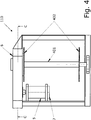
- This preferred embodiment of the driving system 110 is also schematically shown in Figure 2 in a perspective view, in Figure 3 in a side view, and in Figure 4 in a top view.
- Steps 1 of this step band 10 are connected to two chains 2 provided on both sides of the step band 10. For reasons of clarity, only one step 1 of the step band 10 is shown in Figure 1b . Moreover two guides 3 are provided on both sides of the step band 10. The chains 2 run over theses guides 3. Two sprockets 402 with a number of teeth are provided on both sides of the step band 10. The sprockets 201 are in rotationally fixed connection with a first shaft 401 of main shaft of the escalator 100. The chains 2 are moved by the sprockets 402, which engage with chain rollers 201.
- a motor 5 and a brake 7 are provided and are coupled with one of the sprockets 402 via a gearbox 6. This way, mechanical energy produced by the motor 5 can be used to drive the step band 10.
- a truss 11 is provided to support the elements of the conveyor apparatus 100. According to the invention, at least one stage of the gearbox 6 is provided as a cycloidal drive, as will be explained later on in detail.
- the motor 5 and the brake 7 can be located between the chains 2 of the step band 10, such that space requirements in the upper head of the escalator 100 and thus the total length of the escalator 100 can be reduced.
- This length reduction especially reduces the logistic and installation requirements and particularly increases the rigidity of the escalator 100.
- the motor 5 and/or the brake 7 could be connected to the first shaft 401 or to one of the sprockets 402.
- the motor 5 is for example a permanent magnet synchronous motor with radial flux. This motor type presents advantages in torque density and efficiency.
- the brake 7 is in this example connected to a motor shaft of the motor 5. Particularly, the conveyor apparatus 100 can be stopped with by means of an electronic brake or of the motor 5 itself. The brake 7 is adapted to hold the conveyor apparatus 100 once it has stopped. The brake 7 can also have the function of an auxiliary brake. The brake 7 could also be used as service brake. It is also possible to locate the brake 7 in other elements of the driving system 110, for instance, in the main shaft 401.
- Figure 5 a sectional top view of a preferred embodiment of a driving system according to the invention is schematically shown. Particularly, Figure 5 shows a sectional view of the driving system 110 of Figure 3 along the line A-A.
- Figure 6 schematically shows a sectional side view of a preferred embodiment of a driving system according to the invention. Particularly, a sectional side view of the driving system 110 of Figure 4 along the line C-C is shown in Figure 6 .
- the gearbox 6 has at least one gear train 601, 602 with a gear ratio i 1 .
- a first gear 601 is coupled to one of the sprockets 402.
- the first gear 601 is particularly in rotationally fixed connection with the first shaft 401.
- a second gear 602 is supported by bearings 620 to a gearbox frame 650.
- the first shaft 401 is e.g. also supported by bearings 622 in the gearbox frame 650.
- One stage of the gearbox 6 is provided as a cycloidal drive 610.
- the gearbox 6 is adapted to transfer a rotary motion of a second shaft 614 into a rotary motion of the first shaft 401, thus driving the conveyor band 10.
- the second shaft 614 is supported by bearings 621 in the gearbox frame 650.
- This second shaft 614 is an input shaft of the cycloidal drive 610.
- the second shaft is moreover coupled with the motor 5 and the motor 5 is adapted to set the second shaft 614 into rotary motion.
- the second shaft 614 can for example be in rotationally fixed connection with a motor shaft of the motor 5.
- This cycloidal drive 610 comprises at least one eccentric disc 613 (e.g. two eccentric discs 613), which are in rotationally fixed connection with the second shaft 614.
- At least one cycloidal disc 612 (e.g. two cycloidal discs 612) are provided, which can be moved and set in an eccentric cycloidal motion by the eccentric discs 613.
- An external surface 612a of each cycloid disc 612 comprises a number z 2 of lobes. In this example, nine lobes are provided.
- a first pin element (or ring gear element or ring gear housing) comprises a first number z 1 of first pins 611.
- first pins 611 i.e. ten
- This number z 1 of first pins 611 is larger than the number z 2 of lobes (i.e. nine) of each cycloidal disc 612.
- the first pin element is arranged coaxial to the second shaft 614.
- the second gear 602 also acts as this first pin element.
- the first pins 611 are arranged on the second gear 602, particularly on a circumference or circle coaxial to the second shaft 614.
- the cycloidal discs 612 are arranged inside this circumference or circle.
- the first pins 611 roll on the external surface 612a of the cycloidal discs 612.
- a second pin element comprises a number of second pins 615. Particularly, six second pins are provided in this example. These second pins 615 and the second pin element are arranged coaxial to the second shaft 614.
- Each cycloidal disc 612 comprises a number of holes 612b equal to or larger than the number of second pins 615. As shown in Figure 6 , six holes are provided. Thus, the number of second pins 615 and the number of holes 612b are identical in this example.
- the second pins 615 are adapted to engage the holes 612b in the cycloidal discs 612. The second pins 615 can roll over the surface of the holes 612b of the cycloid discs 612.
- the second pins 615 are connected to the gearbox frame 650.
- the gearbox frame 650 acts as the second pin element in this example.
- the second pins 615 are thus fixed in this example and hence also the second pin element is fixed in this embodiment.
- the first pin element i.e. the second gear 602 is pivotable in this embodiment. It is also possible, that the first pin element is fixed and that the second pin element is pivotable, as will be explained later on in reference to Figures 12 and 13 .
- the first shaft 401 is especially set into a rotary movement following a predetermined speed pattern.
- Such a rotation speed pattern 700 of a main shaft of a conveyor apparatus is schematically shown in Figure 7 .
- Figure 7 shows an exemplary rotation speed pattern 700 of the first shaft 401 of the escalator 100 of the Figures 1 to 6 , wherein the main sprocket 402 has e.g. 10 teeth.
- This speed pattern a constant speed of the chains 2 can be achieved.
- This rotation pattern can also be modified, to achieve a predetermined level of vibrations below a reference level without affecting the present invention.
- the external part 612a of the cycloid discs 612 can specifically be designed to either achieve a constant gear ratio i 2 or to achieve a variable gear ratio, as will now be explained with reference to Figures 8 .
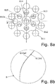
- Figure 8a shows a part of the cycloidal drive 610 of the driving system 110 according to Figures 1 to 6 .
- Figure 8b shows a comparison of two different external surfaces 612a1 and 612a2.
- the external surface 612a1 follows a hypocycloid curve in order to achieve a constant gear ratio i 2 of the cycloidal drive 610.
- a predetermined variable gear ratio can be achieved. In this way, vibrations produced by the polygonal effect associated to the chain transmission can be reduced or eliminated.
- the necessary variations between the different surface profiles 612a1 and 612a2 are comparatively small.
- the optimum profile depends on parameters of the conveyor apparatus, like the number of teeth in the step chain sprocket. In this way, the vibrations produced by the polygonal effect associated to the step chain transmission can be reduced or eliminated.
- Alternative configurations could also be achieved by modifying the inner surfaces 612b and/or the external surfaces 612a of the cycloid discs 612.
- FIGS 9 to 17 schematically show other preferred embodiments of the driving system according to the invention.
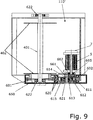
- a preferred embodiment 110' of the driving system according to the invention is schematically shown in a sectional view, wherein the first shaft 614 is not directly connected to the motor shaft, but via another gear, e.g. a gear train 661, 662.
- One gear 661 of this gear train is connected with the first shaft 614 of the cycloidal drive 610 and the other gear 662 of this gear train is connected to a shaft of the motor 5 and the brake 7. This configuration especially allows a higher motor 5 speed.
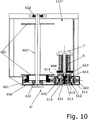
- FIG. 10 shows the driving system 110" with this embodiment of a gearbox 6" in a sectional top view.
- Figure 11 shows this gearbox 6" in a sectional side view.
- the eccentric discs 613 and the cycloidal discs 612 are coupled via this planetary stage 663, 664.
- the cycloidal discs 612 are moved by eccentric discs 613, which are connected to a number of eccentric shafts 616, which are supported by bearings 623 in the gearbox frame 650.
- External gears 663 of the planetary stage move the eccentric shafts 616.
- An internal gear 664 of the planetary stage is connected to the motor 5 and the brake7.
- three shafts with the planetary gears 663 are moving the cycloid discs 612 using the eccentric discs 613, which are in this example not connected to the second shaft 614.
- the pins 615 can e.g. just be fixed if there is enough clearance in the cycloid discs 612 and contribute to the rigidity of the gear box frame 650 or can also be rotating or low speed pins 615.
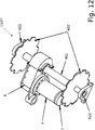
- a corresponding preferred embodiment 110''' of the driving system according to the invention is schematically shown in Figures 12 in a perspective view and in Figure 13 in a sectional top view.
- the gear train 601, 602 of the gearbox is arranged in between the sprockets 402 and the chains 2.
- the first gear 601 is in rotationally fixed connection with the first shaft 401 and the second gear 602 is supported by bearings 620 in the gearbox frame 650.
- the gear box frame 650 has in this example one support point in the first shaft 401, using adequate bearings 624.
- the second gear 602 is in this embodiment provided as the second pin element comprising the second pins 615.
- the z 1 first pins 611 are fixed to the gearbox frame 650.
- the gearbox frame 650 acts as the first pin element in this example.
- the second shaft 614 is also connected with eccentric discs 613, which move the cycloidal disc 612 and set them into an eccentric, cycloidal motion.
- the number z 2 of lobes in the outer surface 612a of the cycloidal disc 612 is smaller than the number z 1 of first pins 611.
- the first pins 611 roll over the outer surfaces 612a of the cycloid discs 612.
- the pins 615 of the low speed shaft 618 roll over the holes 612b in the cycloidal discs 612.
- the cycloid discs in all the above described preferred embodiments of the driving system according to the invention can have modified external curves 612a to specifically reduce or eliminate vibrations due to the polygonal effect.
- FIG 14 Another preferred embodiment 110"" of the driving system according to the invention is schematically shown in Figure 14 in perspective views, wherein the motor 5 is arranged outside the conveyor band or outside the area in between the chains 2.
- Figure 14a schematically shows in a perspective view an upper head of a preferred embodiment of a conveyor apparatus 100"" according to the invention, which is in this example embodied as a moving walkway.
- a conveyor band 10'''' of the moving walkway 100''''' is provided as pallet band.
- the corresponding embodiment of the driving system 110"" without the pallet band 10"” is shown schematically in Figure 14b .
- a double cardan shaft 8 can be used to connect the motor 5 and the gear box 6.
- the motor and the brake can especially be a "pancake" type motor; either a permanent magnet synchronous motors with axial flux or a permanent magnet synchronous motor with radial flux and a diameter larger than the motor width.
- An example of a preferred embodiment of a corresponding driving system 110* is schematically shown in the Figures 15 to 17 .
- Figure 15a schematically shows an upper head of a conveyor apparatus 100*, which is embodied as an escalator.
- the corresponding driving system 110* is shown in Figure 15b in a perspective view and in Figure 15c in a top view.
- Figure 16 shows a sectional view of the driving system 110* of Figure 15 along the line E-E and
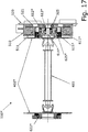
- Figure 17 shows a corresponding sectional view along the line D-D.
- the motor 5* is in this example provided as an axial flux motor with a corresponding brake 7*.
- the cycloid stage of the corresponding gearbox 6* is located in the middle of the motor 5*.
- a stator housing 510 supports coils 511 and a rotor 520 supports magnets 521.
- a corresponding second shaft 614* of the cycloid stage is in this case fixed to the rotor 520 and rotates with it. This shaft 614* moves the corresponding cycloid discs 612* through adequate eccentric discs 613* attached to it.
- the stator housing 510 holds the corresponding number of first pins 611*, which roll over the external cycloid profile 612a* of the cycloid discs 612*.
- Corresponding second pins 615* engage holes 612b* in the cycloid discs 612*.
- the second pins 615* can for example be connected to the sprocket 402*.
- One of the sprocket 402* can be supported by the motor housing 510 by means of an adequate cross roller bearing 625*.
- the other one of the sprockets 402* can be supported by the escalator truss 11 by another adequate bearing 622*.
- the first shaft is in this example provided as a double cardan shaft 403. Both sprockets 402* are connected by means of this double cardan shaft 403.
- first pins 611* to the sprocket 402* and the second pins 615* to the stator housing 510. It is e.g. also possible to modify the external shape of the cycloid discs and to use a conjugate surface instead of the first pins.
Landscapes
- Devices For Conveying Motion By Means Of Endless Flexible Members (AREA)
- Escalators And Moving Walkways (AREA)
Abstract
The present invention relates to a driving system (110) for driving a conveyer band of a conveyer apparatus, especially of an escalator or a moving walkway, comprising a first rotatable shaft (401) coupled with at least one sprocket (402), wherein the at least one sprocket (402) is adapted to be coupled with at least one chain of the conveyer band, a second rotatable shaft (614) coupled with a motor (5), wherein the motor (5) is adapted to set the second rotatable shaft (614) into a rotary motion, wherein a gearbox (6) is provided, which is adapted to transfer the rotary motion of the second shaft (614) into a rotary motion i of the first shaft (401), wherein at least one stage of the gearbox (6) is provided as a cycloidal drive (610).
Description
- The present invention relates to a driving system for driving a conveyer band of a conveyer apparatus and a corresponding conveyer apparatus comprising a first rotatable shaft coupled with at least one sprocket, wherein the at least one sprocket is adapted to be coupled with at least one chain of the conveyer band, and comprising a second rotatable shaft coupled with a motor, wherein the motor is adapted to set the second rotatable shaft into a rotary motion.
- In a conveyer apparatus, e.g. an escalator or a moving walkway, a conveyor band (step band or pallet band) is driven by means of a motor. The conveyor band is usually connected with chains, comprising a plurality of chain links connected by corresponding connection means, e.g. pins, plates, rollers, etc. A main shaft of the conveyer apparatus, usually located in one end of the apparatus, is connected with at least one sprocket. This sprocket has a number of teeth on its circumference, which engage the connection means of the corresponding chain. The motor can convert electric energy into mechanical energy, by means of which the main shaft can be set into rotation, thus moving the conveyor band. A conveyer apparatus of this kind is e.g. described in
EP 1 680 348 A1US 5 950 797 A . - A disadvantage of this kind of conveyor apparatus is that vibrations due to the so called polygon effect are generated, as e.g. described in
EP2 033 928 A1 . Vibrations of that kind arise due to interaction of the chains with the sprockets: A chain comprises several of discrete chain links connected with each other by connection means, such as pins, plates, rollers, etc. The engagement of these connection means with the teeth of the sprocket causes vibration and fluctuation of the chain, which is referred to polygon effect. - These vibrations cause undesirable friction between the chain and the sprocket, thereby reducing the service life time of these components. Moreover, the ride experience of a user of the conveyor apparatus can be negatively affected by this polygon effect. On the one hand, a user can feel these vibrations, which can result in an unpleasant sensation. On the other hand, noise is generated by the vibrations, which can be perceived as annoying by users or by people in the vicinity of the conveyor apparatus.
- It is therefore desirable to provide a possibility to reduce vibrations due to the polygon effect.
- The invention relates to a driving system for driving a conveyer band of a conveyer apparatus and a corresponding conveyer apparatus with the features of the independent claims. Further advantages and embodiments of the invention will become apparent from the description and the appended figures.
- The conveyer apparatus can especially be an escalator or a moving walkway. In case of an escalator, the conveyer band is particularly a step band. In case of a moving walkway, the conveyer band is especially a pallet band.
- A first rotatable shaft is coupled with at least one sprocket. The at least one sprocket is adapted to be coupled with at least one chain of the conveyer band. Particularly, the conveyer band comprises two chains, one on each side of the conveyer apparatus. Hence, the first shaft especially comprises two sprockets, one for each chain. The first shaft is particularly a main shaft or chain wheel drive shaft of the conveyer apparatus. The first shaft can especially be directly connected with the sprockets by means of a rotationally fixed connection.
- Each sprocket especially comprises a profiled wheel with a number of teeth for meshing and engaging connection means of the corresponding chain. These connection means connect the corresponding chain links with each other. Thus, the chain and the conveyor band are moved as the sprocket rotates.
- If the conveyer apparatus comprises more than one chain and thus more than one sprocket, these sprockets can e.g. also be connected by other means than the first shaft, e.g. by another shaft of by other power transmission elements adapted to keep the motion of the chains synchronised.
- A motor or electric machine is provided for driving the conveyor band. Electric energy is converted into mechanical energy by the motor. This mechanical energy is used to drive the conveyor band.
- A second rotatable shaft is coupled with the motor. The motor is adapted to set the second rotatable shaft into a rotary motion. The second rotatable shaft can be coupled directly to the motor. Particularly, the second shaft can be constructed as a motor shaft. It is also possible that the second shaft is coupled to the motor shaft via other elements.
- According to the invention, the driving system comprises a gearbox, which is adapted to transfer the rotary motion of the second shaft into a rotary motion of the first shaft. Herein, at least one stage of the gearbox is provided as a cycloidal drive. Hereby, the at least one sprocket is set into rotatory movement and hence the conveyor band is moved.
- The invention is based on the realisation that the use of a cycloidal drive in a conveyor apparatus yields distinct advantages. Particularly, efficiency of the drive system can be increased and environmental impact can be reduced. Costs and effort for installation, operation, and maintenance of the conveyor apparatus can be reduced.
- By the use of a cycloidal drive vibrations due to the so called polygon effect can be minimised or even prevented. The intensity of the polygon effect particularly depends on the speed of the chain. In conventional drive systems, the speed of the chain can not be controlled precisely enough to reduce vibrations due to the polygon effect. Particularly, the motor does not enable a very accurate control of the chain speed. By means of the cycloidal drive of the gearbox according to the invention, the speed of the chain can expediently be controlled in order to reduce or prevent vibrations due to the polygon effect. Particularly, due to the specific design of the cycloid drive a variable speed pattern of the rotation of the first shaft can be enabled. The cycloid drive is especially specifically designed to enable a specific speed pattern of the first shaft, by means of which a specific speed pattern of the chain, particularly a constant speed chain, can be achieved.
- Thus, by reducing vibrations due to the polygon effect, the riding experience of a user can be improved and noise pollution can be reduced. Moreover, no undesirable friction between the chain and the sprocket is caused, which can arise due to the polygon effect. Thus, the service life time of these components can be increased and maintenance costs can be reduced.
- Moreover, the cycloidal drive has minimal space requirements, especially compared with other kinds of gearboxes. Particularly, by means of the cycloidal drive a relatively high gear ratio can be achieved with minimal space requirements. Thus, dimensions of the conveyor apparatus can be reduced or the saved space can be used for other elements or purposes. Logistics and installation of the conveyor apparatus can hence be simplified.
- There is especially no danger of disconnection of the motor and the first shaft. In common drive systems a motor can be connected to a gearbox, which is connected via a chain, e.g. a duplex or triplex chain, to a main shaft, on which sprockets are arranged. In these conventional systems, there is the danger of e.g. breakage of the duplex or triplex chain or loosening of supporting screws of the motor and the gearbox. In this case, the steps or pallets of the corresponding conveyor band may move without any control, possibly resulting in injuries of passengers or damage of transported goods. These dangers can be prevented by means of the cycloidal drive.
- According to a preferred embodiment, a first gear is provided, which is in rotationally fixed connection with the first shaft. A second gear is provided, which is in rotationally fixed connection with an element of the cycloidal drive. The first gear and the second gear are coupled with each other. Thus, these two gears particularly form a gearbox train, which is preferably provided as a second stage of the gearbox. Particularly, the rotary motion of the second shaft is transferred via the cycloidal drive into a rotary motion of the second gear. In this second stage of the gearbox, this rotary motion of the second gear is transferred into a rotary motion of the first gear and hence into the rotary motion of the first shaft.
- Preferably, the cycloidal drive comprises at least one eccentric disc and at least one cycloidal disc. The at least one cycloidal disc has an external surface with a number of lobes. The at least one eccentric disc is preferably set into rotation by the second shaft. The at least one eccentric disc is adapted to set the at least one cycloidal disc in motion, particularly in an eccentric, cycloidal motion. Particularly, the at least one eccentric disc is arranged in the centre of the at least one cycloidal disc. The at least one cycloidal disc and the at least one eccentric disc are especially coupled with each other via a bearing, e.g. a rolling bearing.
- The second shaft is advantageously in a rotationally fixed connection with the at least one eccentric disc. Thus, the second shaft and the eccentric disc(s) are preferably connected directly with each other. Alternatively, the second shaft is connected with the at least one eccentric disc preferably via a planetary stage of the gearbox. For this purpose, the second shaft can particularly set a pinion in rotary motion, which engages at least one sprocket of the corresponding planetary gear. This at least one sprocket is in particularly in rotationally fixed connection with the at least one eccentric disc.
- Advantageously, the cycloidal drive comprises a first pin element and a second pin element. The first pin element or ring gear element is arranged preferably coaxial to the second shaft and comprises a number of first pins. These first pins are especially arranged on a circumference or circle coaxial to the second shaft. The at least one cycloidal disc is arranged inside this circumference or circle. The number of first pins is preferably larger than the number of lobes of the at least one cycloidal disc. There is especially at least one more first pin than second pins. Particularly, there are at most five more first pins than second pins. Thus, the first pins roll on the external surface of the at least one cycloidal disc. For this purpose, the first pins can be provided as rotating and/or low friction pins.
- The second pin element is preferably also arranged coaxially to the second shaft and comprises a number of second pins. The at least one cycloidal disc comprises a number of holes equal to or larger than the number of second pins. The number of holes and second pins can especially be identical. Particularly, there are at most five more holes than second pins. Preferably, the second pins are adapted to engage the holes in the at least one cycloidal disc. Analogously to the first pins, the second pins can be provided as rotating and/or low friction pins. It is also possible, that the second pin element is connected to sprocket shafts of the aforementioned planetary stage of the gearbox. The second pin element can e.g. also be constructed as a shaft.
- According to a first preferred embodiment, the second pin element is fixed, e.g. to a housing of the motor or of the gear box. The first pin element is in this case preferably pivotable. A corresponding bearing for the first pin element can e.g. be provided in a housing of the gearbox. The rotary motion of the second shaft is thus especially transferred into a rotary motion of the first pin element. The gearbox is in this case preferably adapted to transfer the rotary motion of the second shaft into a rotary motion of the first pin element and to transfer this latter motion into the rotary motion of the first shaft. For this purpose, the first pin element is preferably in rotationally fixed connection with the second gear or the chain sprocket. Thus, rotary motion of the first pin element is transferred into rotary motion of the second gear or of the chain sprocket.
- Alternatively, according to a second preferred embodiment, the first pin element is fixed and the second pin element is pivotable. For example, the first pin element can in this case be fixed to the conveyor apparatus, e.g. to the housing of the motor or of the gear box. A corresponding bearing for the second pin element can be provided in the gearbox housing. The gearbox is in this case preferably adapted to transfer the rotary motion of the second shaft into a rotary motion of the second pin element and to transfer this latter motion into the rotary motion of the first shaft. The second pin element is in this case advantageously in rotationally fixed connection with the second gear or the chain sprocket. Thus, in this case, the rotary motion of the second pin element is transferred into rotary motion of the second gear or the chain sprocket.
- According to an advantageous embodiment, the number of first pins is equal to a number of teeth of the at least one sprocket or equal to an integer multiple of this number of teeth. The number of lobes is preferably equal to the number of first pins minus a ratio between the number of first pins and the number of teeth of the at least one sprocket. The shape of the external surface of the at least one cycloidal disc is thus specifically modified to achieve a specific speed pattern of the first shaft in order to achieve a constant speed of the conveyor band and thus to minimise or even prevent vibrations due to the polygon effect. This configuration is especially advantageous if a gear ratio of the first and the second gear is 1:1 or if a first and a second gear are provided. Moreover, this configuration is particularly advantageous for sprockets with less than 16 teeth. For example, if the number of teeth is 10 and the number of first pins is 10, the number of lobes will especially be 9. If, for instance, the sprockets have 10 teeth and if there are 20 first pins, the cycloidal disc(s) will especially have 18 lobes.
- Preferably, the number of first pins is equal to a number of teeth of the at least one sprocket multiplied by a factor y or equal to an integer multiple of the number of teeth of the at least one sprocket multiplied by the factor y. This factor y preferably corresponds to a gear ratio of y:1 of the number of teeth of the second gear and the number of teeth of the first gear. The number of lobes is preferably equal to the number of first pins minus a ratio between the number of first pins and the number of teeth of the at least one sprocket multiplied by the factor y. This configuration is also particularly advantageous for sprockets with less than 16 teeth. Also by this specific shape of the external surface of the cycloidal disc(s) a specific speed pattern of the first shaft and a constant speed of the conveyor band can especially be achieved in order to minimise or prevent vibrations due to the polygon effect.
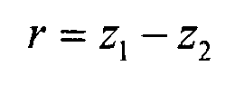
- According to a preferred embodiment, the number first pins z1 is given according to the formula, if z1 is an integer number:

- r is the difference of the number first pins z1 and the number of lobes z2:
- t1 is the number of teeth of the at least one sprocket.
- i1 is the gear ratio of the number of teeth of the second gear and the number of teeth of the first gear.
- This configuration also yields the possibility to minimise or prevent vibrations due to the polygon effect.
- Preferably, the second rotatable shaft is coupled to a shaft of the motor via a second gearbox, e.g. via a gear train with one gear connected with the motor shaft and one gear connected with the second shaft. This configuration particularly allows higher motor speeds.
- The motor can be of an expedient design. According to a particularly advantageous embodiment, the motor is a permanent magnet synchronous motor (PMSM). This motor type presents advantages in torque density and efficiency.
- Preferably, the motor is a PMSM with an axial flux or with radial flux with a diameter larger than the length (so called "pancake" type PMSM). In an axial flux motor of this kind, the magnetic force (through the air gap) is along the same plane as the motor shaft, i.e. along the length of the motor. The motor shaft or an output shaft coupled with the motor shaft is particularly arranged parallel with the first shaft of the conveyor apparatus.
- The motor can preferably be a PMSM with radial flux or with an axial flux with several discs (so called "sausage" type PMSM). In a radial flux motor of this kind, the magnetic force is perpendicular to the length of the motor or motor shaft. This PMSM with radial flux particularly has a longer, skinnier design than the "pancake" type PMSM.
- It is possible to arrange the motor and/or the gearbox in between the two chains of the conveyor band. This design can be appropriate for escalators. The motor and/or the gearbox can also be arranged outside of the area between these two chains and especially outside a truss of the conveyor apparatus. This design can be advantageous for moving walkways. It is also possible to e.g. arrange the motor in between the two chains and the gearbox on the outside of the truss.
- It shall be understood that the driving system may comprise other elements, e.g. a brake and/or a handrail drive. For example a brake can be provided and can interact e.g. with the motor, the first shaft, the second shaft and/or other elements. The brake can have a holding function in order to stop a motion of the conveyor band. Moreover, the brake can have an emergency braking function.
- A handrail drive can be provided to set one or several handrails of the conveyor apparatus in motion. The handrail drive can e.g. also be driven by the motor and can be coupled to the motor by means of power transmission, e.g. belts or chains. The handrail drive can also be driven by means of a mechanical connection with the at least one chain of the conveyor apparatus. It is also possible that a second motor for driving the handrails is provided, which is especially synchronised with the motor of the driving system.
- Moreover, the conveyor apparatus especially comprises one or several of the following elements: a guiding system for the conveyor band and/or the chains; a supporting structure, e.g. a truss; plates provided to transfer passengers from the conveyor band to the surrounding area and vice versa; balustrades provided on both sides of the conveyor apparatus; handrails provided on both sides of the conveyor apparatus moving substantially at the same speed of conveyor band; control and/or safety systems.
- It should be noted that the previously mentioned features and the features to be further described in the following are usable not only in the respectively indicated combination, but also in further combinations or taken alone, without departing from the scope of the present invention.
- The present invention will now be described further, by way of example, with reference to the accompanying drawings, in which
- Figures 1a, 1b
- schematically show a conveyor apparatus with a preferred embodiment of a driving system according to the invention in perspective views.
- Figure 2
- schematically shows a preferred embodiment of a driving system according to the invention in a perspective view.
- Figure 3
- schematically shows a preferred embodiment of a driving system according to the invention in a side view.
- Figure 4
- schematically shows a preferred embodiment of a driving system according to the invention in a top view.
- Figure 5
- schematically shows a preferred embodiment of a driving system according to the invention in sectional top view.
- Figure 6
- schematically shows a gearbox of a preferred embodiment of a driving system according to the invention in a sectional side view.
- Figure 7
- schematically shows a rotation speed pattern of a main shaft of a preferred embodiment of a driving system according to the invention.
- Figure 8
- schematically shows a part of a cycloidal drive of a preferred embodiment of a driving system according to the invention in a side view.
- Figure 9
- schematically shows a preferred embodiment of a driving system according to the invention in a top view
- Figure 10
- schematically shows a preferred embodiment of a driving system according to the invention in a top view.
- Figure 11
- schematically shows a gearbox of a preferred embodiment of a driving system according to the invention in a sectional side view.
- Figure 12
- schematically shows a preferred embodiment of a driving system according to the invention in a perspective view.
- Figure 13
- schematically shows a preferred embodiment of a driving system according to the invention in a sectional top view.
- Figure 14
- schematically shows a section of a conveyor apparatus with a preferred embodiment of a driving system according to the invention in a perspective view.
- Figure 15
- schematically shows a section of a conveyor apparatus with a preferred embodiment of a driving system according to the invention.
- Figure 16
- schematically shows a gearbox of a preferred embodiment of a driving system according to the invention in a sectional side view.
- Figure 17
- schematically shows a preferred embodiment of a driving system according to the invention in sectional top view.
- Identical reference signs in the figures refer to identical or identically constructed elements.
-
Figures 1a, 1b schematically show a preferred embodiment of aconveyor apparatus 100 according to the invention. In this example, theconveyor apparatus 100 is an escalator. -
Figure 1a schematically shows theescalator 100 in a perspective view, which is provided between a first,lower floor 101 and a second,higher floor 102. Theescalator 100 comprises aconveyor band 10, which is provided as a step band comprising a plurality ofsteps 1. Furthermore, theescalator 100 comprises twohandrails 103, one handrail on each side of theconveyor band 10. - An
upper head 104 of theescalator 100 is shown inFigure 1b in a perspective view. - A preferred embodiment of a
driving system 110 according to the invention for driving theconveyer band 10 of theconveyer apparatus 100 is provided in theupper head 104. This preferred embodiment of thedriving system 110 is also schematically shown inFigure 2 in a perspective view, inFigure 3 in a side view, and inFigure 4 in a top view. -
Steps 1 of thisstep band 10 are connected to twochains 2 provided on both sides of thestep band 10. For reasons of clarity, only onestep 1 of thestep band 10 is shown inFigure 1b . Moreover twoguides 3 are provided on both sides of thestep band 10. Thechains 2 run over theses guides 3. Twosprockets 402 with a number of teeth are provided on both sides of thestep band 10. The sprockets 201 are in rotationally fixed connection with afirst shaft 401 of main shaft of theescalator 100. Thechains 2 are moved by thesprockets 402, which engage with chain rollers 201. - A
motor 5 and abrake 7 are provided and are coupled with one of thesprockets 402 via agearbox 6. This way, mechanical energy produced by themotor 5 can be used to drive thestep band 10. Atruss 11 is provided to support the elements of theconveyor apparatus 100. According to the invention, at least one stage of thegearbox 6 is provided as a cycloidal drive, as will be explained later on in detail. - As can be seen in the figures, the
motor 5 and thebrake 7 can be located between thechains 2 of thestep band 10, such that space requirements in the upper head of theescalator 100 and thus the total length of theescalator 100 can be reduced. This length reduction especially reduces the logistic and installation requirements and particularly increases the rigidity of theescalator 100. - However, it is also possible to arrange the
motor 5 and/or thebrake 7 at different locations of theescalator 100. For instance, thebrake 7 could be connected to thefirst shaft 401 or to one of thesprockets 402. - The
motor 5 is for example a permanent magnet synchronous motor with radial flux. This motor type presents advantages in torque density and efficiency. Thebrake 7 is in this example connected to a motor shaft of themotor 5. Particularly, theconveyor apparatus 100 can be stopped with by means of an electronic brake or of themotor 5 itself. Thebrake 7 is adapted to hold theconveyor apparatus 100 once it has stopped. Thebrake 7 can also have the function of an auxiliary brake. Thebrake 7 could also be used as service brake. It is also possible to locate thebrake 7 in other elements of thedriving system 110, for instance, in themain shaft 401. - In
Figure 5 , a sectional top view of a preferred embodiment of a driving system according to the invention is schematically shown. Particularly,Figure 5 shows a sectional view of thedriving system 110 ofFigure 3 along the line A-A. -
Figure 6 schematically shows a sectional side view of a preferred embodiment of a driving system according to the invention. Particularly, a sectional side view of thedriving system 110 ofFigure 4 along the line C-C is shown inFigure 6 . - As can be seen in
Figure 5 andFigure 6 , thegearbox 6 has at least onegear train first gear 601 is coupled to one of thesprockets 402. For this purpose, thefirst gear 601 is particularly in rotationally fixed connection with thefirst shaft 401. Asecond gear 602 is supported bybearings 620 to agearbox frame 650. Thefirst shaft 401 is e.g. also supported bybearings 622 in thegearbox frame 650. - One stage of the
gearbox 6 is provided as acycloidal drive 610. Thegearbox 6 is adapted to transfer a rotary motion of asecond shaft 614 into a rotary motion of thefirst shaft 401, thus driving theconveyor band 10. Thesecond shaft 614 is supported bybearings 621 in thegearbox frame 650. - This
second shaft 614 is an input shaft of thecycloidal drive 610. The second shaft is moreover coupled with themotor 5 and themotor 5 is adapted to set thesecond shaft 614 into rotary motion. As can be seen inFigure 5 , thesecond shaft 614 can for example be in rotationally fixed connection with a motor shaft of themotor 5. - This
cycloidal drive 610 comprises at least one eccentric disc 613 (e.g. two eccentric discs 613), which are in rotationally fixed connection with thesecond shaft 614. - At least one cycloidal disc 612 (e.g. two cycloidal discs 612) are provided, which can be moved and set in an eccentric cycloidal motion by the
eccentric discs 613. Anexternal surface 612a of eachcycloid disc 612 comprises a number z2 of lobes. In this example, nine lobes are provided. - A first pin element (or ring gear element or ring gear housing) comprises a first number z1 of
first pins 611. In this example, ten first pins are provided. This number z1 of first pins 611 (i.e. ten) is larger than the number z2 of lobes (i.e. nine) of eachcycloidal disc 612. The first pin element is arranged coaxial to thesecond shaft 614. - In the example of
Figures 5 and6 , thesecond gear 602 also acts as this first pin element. Thus, thefirst pins 611 are arranged on thesecond gear 602, particularly on a circumference or circle coaxial to thesecond shaft 614. Thecycloidal discs 612 are arranged inside this circumference or circle. Thus, thefirst pins 611 roll on theexternal surface 612a of thecycloidal discs 612. - A second pin element comprises a number of second pins 615. Particularly, six second pins are provided in this example. These
second pins 615 and the second pin element are arranged coaxial to thesecond shaft 614. Eachcycloidal disc 612 comprises a number ofholes 612b equal to or larger than the number of second pins 615. As shown inFigure 6 , six holes are provided. Thus, the number ofsecond pins 615 and the number ofholes 612b are identical in this example. The second pins 615 are adapted to engage theholes 612b in thecycloidal discs 612. The second pins 615 can roll over the surface of theholes 612b of thecycloid discs 612. - In the example of
Figures 5 and6 , thesecond pins 615 are connected to thegearbox frame 650. Thus, thegearbox frame 650 acts as the second pin element in this example. The second pins 615 are thus fixed in this example and hence also the second pin element is fixed in this embodiment. The first pin element, i.e. thesecond gear 602, is pivotable in this embodiment. It is also possible, that the first pin element is fixed and that the second pin element is pivotable, as will be explained later on in reference toFigures 12 and13 . - One of the advantages of the
cycloidal drive 610 is that it allows a relatively high gear ratio with comparatively small space requirements. The gear ratio i2 of thecycloidal drive 610 is especially given by the following formula:
- Another distinct advantage of using the cycloidal drive is that it can be specifically designed to reduce or prevent vibrations due to the polygonal effect. For his purpose, the
first shaft 401 is especially set into a rotary movement following a predetermined speed pattern. Such arotation speed pattern 700 of a main shaft of a conveyor apparatus is schematically shown inFigure 7 . - Particularly,
Figure 7 shows an exemplaryrotation speed pattern 700 of thefirst shaft 401 of theescalator 100 of theFigures 1 to 6 , wherein themain sprocket 402 has e.g. 10 teeth. By this speed pattern, a constant speed of thechains 2 can be achieved. This rotation pattern can also be modified, to achieve a predetermined level of vibrations below a reference level without affecting the present invention. - The
external part 612a of thecycloid discs 612 can specifically be designed to either achieve a constant gear ratio i2 or to achieve a variable gear ratio, as will now be explained with reference toFigures 8 . -
Figure 8a shows a part of thecycloidal drive 610 of thedriving system 110 according toFigures 1 to 6 . An enlarged view of the section referred to as "B", which is a part of theexternal surface 612a of thecycloid discs 612, is schematically shown inFigure 8b . Particularly,Figure 8b shows a comparison of two different external surfaces 612a1 and 612a2. - The external surface 612a1 follows a hypocycloid curve in order to achieve a constant gear ratio i2 of the
cycloidal drive 610. By means of the modified profile 612a2, a predetermined variable gear ratio can be achieved. In this way, vibrations produced by the polygonal effect associated to the chain transmission can be reduced or eliminated. As can be seen inFigure 8 , the necessary variations between the different surface profiles 612a1 and 612a2 are comparatively small. - The optimum profile depends on parameters of the conveyor apparatus, like the number of teeth in the step chain sprocket. In this way, the vibrations produced by the polygonal effect associated to the step chain transmission can be reduced or eliminated.
- The modified profile 612a2 can e.g. be developed, if
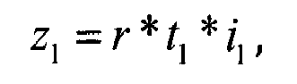
- r is the difference of the number first pins z1 and the number of lobes z2:

- In the configurations in which such gear train does not exist, then the modified profile 612a2 can also be developed if z 1 = r*t 1 . Alternative configurations could also be achieved by modifying the
inner surfaces 612b and/or theexternal surfaces 612a of thecycloid discs 612. -
Figures 9 to 17 schematically show other preferred embodiments of the driving system according to the invention. - In
Figure 9 a preferred embodiment 110' of the driving system according to the invention is schematically shown in a sectional view, wherein thefirst shaft 614 is not directly connected to the motor shaft, but via another gear, e.g. agear train - One
gear 661 of this gear train is connected with thefirst shaft 614 of thecycloidal drive 610 and theother gear 662 of this gear train is connected to a shaft of themotor 5 and thebrake 7. This configuration especially allows ahigher motor 5 speed. - Another
preferred embodiment 110" of the driving system according to the invention is schematically shown inFigures 10 and11 , according to which thegearbox 6" comprises another stage provided as aplanetary stage Figure 10 shows thedriving system 110" with this embodiment of agearbox 6" in a sectional top view.Figure 11 shows thisgearbox 6" in a sectional side view. - The
eccentric discs 613 and thecycloidal discs 612 are coupled via thisplanetary stage cycloidal discs 612 are moved byeccentric discs 613, which are connected to a number ofeccentric shafts 616, which are supported bybearings 623 in thegearbox frame 650. External gears 663 of the planetary stage move theeccentric shafts 616. Aninternal gear 664 of the planetary stage is connected to themotor 5 and the brake7. - In this example, three shafts with the
planetary gears 663 are moving thecycloid discs 612 using theeccentric discs 613, which are in this example not connected to thesecond shaft 614. Thepins 615 can e.g. just be fixed if there is enough clearance in thecycloid discs 612 and contribute to the rigidity of thegear box frame 650 or can also be rotating or low speed pins 615. - As aforementioned it is also possible that the first pin element is fixed and that the second and that the second pin element is pivotable. A corresponding preferred embodiment 110''' of the driving system according to the invention is schematically shown in
Figures 12 in a perspective view and inFigure 13 in a sectional top view. - In this embodiment 110''', the
gear train sprockets 402 and thechains 2. Analogously to theFigures 1 to 6 , thefirst gear 601 is in rotationally fixed connection with thefirst shaft 401 and thesecond gear 602 is supported bybearings 620 in thegearbox frame 650. Thegear box frame 650 has in this example one support point in thefirst shaft 401, usingadequate bearings 624. - The
second gear 602 is in this embodiment provided as the second pin element comprising the second pins 615. In this example, the z1 first pins 611 are fixed to thegearbox frame 650. Thegearbox frame 650 acts as the first pin element in this example. - Analogously to
Figures 1 to 6 , thesecond shaft 614 is also connected witheccentric discs 613, which move thecycloidal disc 612 and set them into an eccentric, cycloidal motion. The number z2 of lobes in theouter surface 612a of thecycloidal disc 612 is smaller than the number z1 offirst pins 611. The first pins 611 roll over theouter surfaces 612a of thecycloid discs 612. Thepins 615 of the low speed shaft 618 roll over theholes 612b in thecycloidal discs 612. - With this configuration, the gear ratio i2 of the
second shaft 614 to the low speed shaft 618 is given as:
- As explained before, the cycloid discs in all the above described preferred embodiments of the driving system according to the invention can have modified
external curves 612a to specifically reduce or eliminate vibrations due to the polygonal effect. - Another
preferred embodiment 110"" of the driving system according to the invention is schematically shown inFigure 14 in perspective views, wherein themotor 5 is arranged outside the conveyor band or outside the area in between thechains 2.Figure 14a schematically shows in a perspective view an upper head of a preferred embodiment of aconveyor apparatus 100"" according to the invention, which is in this example embodied as a moving walkway. A conveyor band 10'''' of the moving walkway 100'''' is provided as pallet band. The corresponding embodiment of thedriving system 110"" without thepallet band 10"" is shown schematically inFigure 14b . In order to reduce the number of gears, adouble cardan shaft 8 can be used to connect themotor 5 and thegear box 6. - It is also possible to locate the motor and the brake on one side of the first shaft. In such cases, the motor can especially be a "pancake" type motor; either a permanent magnet synchronous motors with axial flux or a permanent magnet synchronous motor with radial flux and a diameter larger than the motor width. An example of a preferred embodiment of a
corresponding driving system 110* is schematically shown in theFigures 15 to 17 . -
Figure 15a schematically shows an upper head of aconveyor apparatus 100*, which is embodied as an escalator. Thecorresponding driving system 110* is shown inFigure 15b in a perspective view and inFigure 15c in a top view.Figure 16 shows a sectional view of thedriving system 110* ofFigure 15 along the line E-E andFigure 17 shows a corresponding sectional view along the line D-D. - The
motor 5* is in this example provided as an axial flux motor with acorresponding brake 7*. The cycloid stage of thecorresponding gearbox 6* is located in the middle of themotor 5*. Astator housing 510 supports coils 511 and arotor 520 supportsmagnets 521. A correspondingsecond shaft 614* of the cycloid stage is in this case fixed to therotor 520 and rotates with it. Thisshaft 614* moves the correspondingcycloid discs 612* through adequateeccentric discs 613* attached to it. Thestator housing 510 holds the corresponding number offirst pins 611*, which roll over theexternal cycloid profile 612a* of thecycloid discs 612*. - Corresponding
second pins 615* engageholes 612b* in thecycloid discs 612*. The second pins 615* can for example be connected to thesprocket 402*. One of thesprocket 402* can be supported by themotor housing 510 by means of an adequatecross roller bearing 625*. The other one of thesprockets 402* can be supported by theescalator truss 11 by anotheradequate bearing 622*. The first shaft is in this example provided as adouble cardan shaft 403. Bothsprockets 402* are connected by means of thisdouble cardan shaft 403. - It is also possible to connect the
first pins 611* to thesprocket 402* and thesecond pins 615* to thestator housing 510. It is e.g. also possible to modify the external shape of the cycloid discs and to use a conjugate surface instead of the first pins. -
- 100
- conveyor apparatus, escalator
- 101
- first floor
- 102
- second floor
- 103
- handrail
- 104
- upper head of the
conveyor apparatus 100 - 100''''
- conveyor apparatus, moving walkway
- 100*
- conveyor apparatus, escalator
- 110
- driving system
- 110'
- driving system
- 110"
- driving system
- 110'''
- driving system
- 110''''
- driving system
- 110*
- driving system
- 1
- Steps of the
conveyor band 10 - 2
- chains
- 3
- guides
- 5
- motor
- 5*
- motor
- 6
- gearbox
- 6"
- gearbox
- 6*
- gearbox
- 7
- brake
- 7*
- brake
- 8
- cardan shaft
- 10
- conveyor band, step band
- 10""
- conveyor band, pallet band
- 11
- truss
- 201
- chain rollers
- 401
- first shaft
- 402
- sprockets
- 402*
- sprockets
- 403
- first shaft, double cardan shaft
- 510
- stator housing
- 511
- coils
- 520
- rotor
- 521
- magnets
- 601
-
first gear 601 - 602
- second gear
- 610
- cycloidal drive; cycloidal stage of the
gearbox 6 - 611
- first pins
- 612
- cycloidal disc(s)
- 612a
- external surface of the cycloid disc(s) 612
- 612b
- holes in the cycloidal disc(s)
- 612a1
- hypocycloid curve
- 612a2
- modified curve
- 613
- eccentric disc(s)
- 614
- second shaft
- 615
- second pins
- 616
- eccentric shaft
- 618
- low speed shaft
- 620
- bearings of the
second gear 602 - 621
- bearings of the
second shaft 614 - 622
- bearings of the
first shaft 401 - 623
- bearings of the eccentric shafts
- 624
- bearing
- 650
- gearbox frame
- 661
- gear of gear train
- 662
- gear of a gear train
- 663
- external gears of a planetary stage of the
gearbox 6 - 664
- internal gear of a planetary stage of the
gearbox 6 - 665
- bearings of the motor shaft
- 611*
- first pins
- 612*
- cycloid discs
- 612a*
- external surface of the
eccentric discs 612* - 612b*
- holes in the
cycloid discs 612* - 613*
- eccentric discs
- 614*
- second shaft
- 615*
- second pins
- 622*
- bearing
- 625*
- bearing
- 700
- rotation speed pattern
Claims (15)
- Driving system (110, 110', 110", 110''', 110"", 110*) for driving a conveyer band (10) of a conveyer apparatus (100, 100"", 100*), especially of an escalator or a moving walkway, comprising:a first rotatable shaft (401, 403) coupled with at least one sprocket (402, 402*), wherein the at least one sprocket (402, 402*) is adapted to be coupled with at least one chain (201) of the conveyer band (10),a second rotatable shaft (614) coupled with a motor (5, 5*), wherein the motor (5, 5*) is adapted to set the second rotatable shaft (614) into a rotary motion,characterised in that
a gearbox (6, 6", 6*) is provided, which is adapted to transfer the rotary motion of the second shaft (614) into a rotary motion of the first shaft (401, 403), wherein at least one stage of the gearbox (6, 6", 6*) is provided as a cycloidal drive (610). - Driving system (110, 110', 110", 110''', 110"", 110*) according to claim 1, wherein a first gear (601) is provided, which is in rotationally fixed connection with the first shaft (401, 403), wherein a second gear (602) is provided, which is in rotationally fixed connection with an element of the cycloidal drive (601), and wherein the first gear (601) and the second gear (602) are coupled with each other.
- Driving system (110, 110', 110", 110''', 110"", 110*) according to claim 1 or 2, wherein the cycloidal drive (610) comprises at least one eccentric disc (613) and at least one cycloidal disc (612), wherein the at least one cycloidal disc (612) has an external surface (612a) with a number of lobes and wherein the at least one eccentric disc (613) is adapted to set the at least one cycloidal disc (612) in motion.
- Driving system (110, 110', 110", 110''', 110"", 110*) according to claim 3, wherein
the second shaft (614) is in a rotationally fixed connection with the at least one eccentric disc (613) or
the second shaft (614) is connected with the at least one eccentric disc (613) via a planetary stage (663, 664) of the gearbox (6, 6", 6*). - Driving system (110, 110', 110", 110''', 110"", 110*) according to claim 3 or 4, wherein the cycloidal drive (610) comprises a first pin element and a second pin element,
wherein the first pin element is arranged coaxial to the second shaft (614) and comprises a number of first pins (611), wherein the number of first pins (611) is larger than the number of lobes of the at least one cycloidal disc (612), and
wherein the second pin element is arranged coaxial to the second shaft (614) and comprises a number of second pins (615), wherein the at least one cycloidal disc (612) comprises a number of holes (612b) equal to or larger than the number of second pins (615) and wherein the second pins (615) are adapted to engage the holes (612b) in the at least one cycloidal disc (612). - Driving system (110, 110', 110", 110''', 110"", 110*) according to claim 5, wherein the second pin element is fixed and wherein the gearbox (6, 6", 6*) is adapted to transfer a rotary motion of the first pin element into the rotary motion of the first shaft (401, 403).
- Driving system (110, 110', 110", 110''', 110"", 110*) according to claim 2 and 6, wherein the first pin element is in a rotationally fixed connection with the second gear (602).
- Driving system (110, 110', 110", 110''', 110"", 110*) according to claim 5, wherein the first pin element is fixed and wherein the gearbox (6, 6", 6*) is adapted to transfer a rotary motion of the second pin element into the rotary motion of the first shaft (401, 403).
- Driving system (110, 110', 110", 110''', 110"", 110*) according to claim 2 and 8, wherein the second pin element is in a rotationally fixed connection with the second gear (602).
- Driving system (110, 110', 110", 110''', 110"", 110*) according to any one of the preceding claims when dependent upon claim 5,
wherein the number of first pins (611) is equal to a number of teeth of the at least one sprocket (402, 402*) or equal to an integer multiple of this number of teeth and
wherein the number of lobes is equal to the number of first pins (611) minus a ratio between the number of first pins (611) and the number of teeth of the at least one sprocket (402, 402*). - Driving system (110, 110', 110", 110''', 110"", 110*) according to any one of the preceding claims when dependent upon claim 2 and 5,
wherein the number of first pins (611) is equal to a number of teeth of the at least one sprocket (402, 402*) multiplied by a factor y or equal to an integer multiple of the number of teeth of the at least one sprocket (402, 402*) multiplied by the factor y,
wherein the factor y corresponds to a gear ratio of y:1 of the first gear (601) and the second gear (602),
wherein the number of lobes is equal to the number of first pins (611) minus a ratio between the number of first pins (611) and the number of teeth of the at least one sprocket (402, 402*) multiplied by the factor y. - Driving system (110, 110', 110", 110''', 110"", 110*) according to any one of the preceding claims when dependent upon claim 2 and 5, wherein the number first pins z1 is given according to the formula
 if zi is an integer number, with:
 t1 being a number of teeth of the at least one sprocket (402, 402*),i1 being the ratio of the number of teeth of the second gear (602) and the number of teeth of the first gear (601).
 - Driving system (110, 110', 110", 110''', 110"", 110*) according to any one of the preceding claims, wherein the second rotatable shaft (614) is coupled to a shaft of the motor (5, 5*) via a second gearbox (661, 662).
- Driving system (110, 110', 110", 110''', 110"", 110*) according to any one of the preceding claims, wherein the motor (5, 5*) is a permanent magnet synchronous motor.
- Conveyer apparatus (100, 100"", 100*), especially of an escalator or a moving walkway, comprising a driving system (110, 110', 110", 110''', 110"", 110*) for driving a conveyer band (10) according to any one of the preceding claims.
Priority Applications (4)
| Application Number | Priority Date | Filing Date | Title |
|---|---|---|---|
| EP17380003.8A EP3354615A1 (en) | 2017-01-31 | 2017-01-31 | Driving system for driving a conveyer band of a conveyer apparatus |
| CN201880009335.6A CN110234591B (en) | 2017-01-31 | 2018-01-29 | Drive systems for driving conveyor belts of conveyor systems |
| PCT/EP2018/052126 WO2018141687A1 (en) | 2017-01-31 | 2018-01-29 | Driving system for driving a conveyer band of a conveyer apparatus |
| EP18701055.8A EP3577049A1 (en) | 2017-01-31 | 2018-01-29 | Driving system for driving a conveyer band of a conveyer apparatus |
Applications Claiming Priority (1)
| Application Number | Priority Date | Filing Date | Title |
|---|---|---|---|
| EP17380003.8A EP3354615A1 (en) | 2017-01-31 | 2017-01-31 | Driving system for driving a conveyer band of a conveyer apparatus |
Publications (1)
| Publication Number | Publication Date |
|---|---|
| EP3354615A1 true EP3354615A1 (en) | 2018-08-01 |
Family
ID=58046603
Family Applications (2)
| Application Number | Title | Priority Date | Filing Date |
|---|---|---|---|
| EP17380003.8A Withdrawn EP3354615A1 (en) | 2017-01-31 | 2017-01-31 | Driving system for driving a conveyer band of a conveyer apparatus |
| EP18701055.8A Withdrawn EP3577049A1 (en) | 2017-01-31 | 2018-01-29 | Driving system for driving a conveyer band of a conveyer apparatus |
Family Applications After (1)
| Application Number | Title | Priority Date | Filing Date |
|---|---|---|---|
| EP18701055.8A Withdrawn EP3577049A1 (en) | 2017-01-31 | 2018-01-29 | Driving system for driving a conveyer band of a conveyer apparatus |
Country Status (3)
| Country | Link |
|---|---|
| EP (2) | EP3354615A1 (en) |
| CN (1) | CN110234591B (en) |
| WO (1) | WO2018141687A1 (en) |
Cited By (2)
| Publication number | Priority date | Publication date | Assignee | Title |
|---|---|---|---|---|
| WO2020054065A1 (en) * | 2018-09-14 | 2020-03-19 | 三菱電機株式会社 | Emergency braking device for passenger conveyor |
| WO2025144386A1 (en) * | 2023-12-29 | 2025-07-03 | Yavuz Davut | Innovation in the walkway belt |
Families Citing this family (1)
| Publication number | Priority date | Publication date | Assignee | Title |
|---|---|---|---|---|
| US10625985B1 (en) * | 2019-01-25 | 2020-04-21 | Kone Corporation | Pedestrian conveyor mass damper to reduce step vibration |
Citations (5)
| Publication number | Priority date | Publication date | Assignee | Title |
|---|---|---|---|---|
| US5950797A (en) | 1996-02-29 | 1999-09-14 | Kone Oy | People mover and drive apparatus |
| EP1680348A1 (en) | 2003-11-03 | 2006-07-19 | Kone Oyj (Kone Corporation) | Conveyor |
| US20080067034A1 (en) * | 2006-09-19 | 2008-03-20 | Thomas Illedits | Escalator or moving walk with drive |
| EP2033928A1 (en) | 2007-09-05 | 2009-03-11 | ThyssenKrupp Elevator (ES/PBB) Ltd. | Turnaround curve system for a chain conveyor system. |
| WO2016175188A1 (en) * | 2015-04-30 | 2016-11-03 | 国立大学法人東京工業大学 | Planetary roller drive-type inscribed planetary gear reduction device |
Family Cites Families (3)
| Publication number | Priority date | Publication date | Assignee | Title |
|---|---|---|---|---|
| JP2005187202A (en) * | 2003-12-26 | 2005-07-14 | Toshiba Elevator Co Ltd | Conveyer apparatus |
| CN104555684B (en) * | 2014-12-12 | 2017-03-29 | 浙江西子富沃德电机有限公司 | A kind of escalator or moving sidewalk and its driving means |
| JP2017100819A (en) * | 2015-11-30 | 2017-06-08 | 東芝エレベータ株式会社 | Passenger conveyor |
-
2017
- 2017-01-31 EP EP17380003.8A patent/EP3354615A1/en not_active Withdrawn
-
2018
- 2018-01-29 CN CN201880009335.6A patent/CN110234591B/en not_active Expired - Fee Related
- 2018-01-29 WO PCT/EP2018/052126 patent/WO2018141687A1/en not_active Ceased
- 2018-01-29 EP EP18701055.8A patent/EP3577049A1/en not_active Withdrawn
Patent Citations (5)
| Publication number | Priority date | Publication date | Assignee | Title |
|---|---|---|---|---|
| US5950797A (en) | 1996-02-29 | 1999-09-14 | Kone Oy | People mover and drive apparatus |
| EP1680348A1 (en) | 2003-11-03 | 2006-07-19 | Kone Oyj (Kone Corporation) | Conveyor |
| US20080067034A1 (en) * | 2006-09-19 | 2008-03-20 | Thomas Illedits | Escalator or moving walk with drive |
| EP2033928A1 (en) | 2007-09-05 | 2009-03-11 | ThyssenKrupp Elevator (ES/PBB) Ltd. | Turnaround curve system for a chain conveyor system. |
| WO2016175188A1 (en) * | 2015-04-30 | 2016-11-03 | 国立大学法人東京工業大学 | Planetary roller drive-type inscribed planetary gear reduction device |
Cited By (3)
| Publication number | Priority date | Publication date | Assignee | Title |
|---|---|---|---|---|
| WO2020054065A1 (en) * | 2018-09-14 | 2020-03-19 | 三菱電機株式会社 | Emergency braking device for passenger conveyor |
| JPWO2020054065A1 (en) * | 2018-09-14 | 2021-01-07 | 三菱電機株式会社 | Emergency braking device for passenger conveyor |
| WO2025144386A1 (en) * | 2023-12-29 | 2025-07-03 | Yavuz Davut | Innovation in the walkway belt |
Also Published As
| Publication number | Publication date |
|---|---|
| EP3577049A1 (en) | 2019-12-11 |
| CN110234591B (en) | 2021-11-02 |
| CN110234591A (en) | 2019-09-13 |
| WO2018141687A1 (en) | 2018-08-09 |
Similar Documents
| Publication | Publication Date | Title |
|---|---|---|
| EP2341028B1 (en) | Drive system for escalators and moving walkways | |
| AU2007216821B2 (en) | Escalator or moving walk with drive | |
| JP4892169B2 (en) | Escalator drive device | |
| US5224580A (en) | Power transmission system for a passenger conveyor | |
| CN100537394C (en) | Passenger conveyor drive machine | |
| EP3577049A1 (en) | Driving system for driving a conveyer band of a conveyer apparatus | |
| HK40014025A (en) | Driving system for driving a conveyer band of a conveyer apparatus | |
| JP2004527433A (en) | Escalator or moving sidewalk driving device | |
| JP4969014B2 (en) | Passenger conveyor and passenger conveyor drive | |
| HK40014025B (en) | Driving system for driving a conveyer band of a conveyer apparatus | |
| EP3243788B1 (en) | Passenger conveyor | |
| EP3543195A1 (en) | People conveyor and drive for a people conveyor | |
| US12410038B1 (en) | Dynamic comb for conveyance systems for moving people or objects | |
| JP2007076755A (en) | Passenger conveyor device | |
| KR200314359Y1 (en) | Elevator traction machine | |
| FI103104B (en) | Passenger conveyor and drive | |
| HK1086242B (en) | Passenger conveyor drive machine | |
| TH56767B (en) | Escalators or moving walkways with drive units | |
| TH93468A (en) | Escalators or moving walkways with drive units | |
| HK1118787B (en) | Escalator or moving walkway with drive |
Legal Events
| Date | Code | Title | Description |
|---|---|---|---|
| PUAI | Public reference made under article 153(3) epc to a published international application that has entered the european phase |
Free format text: ORIGINAL CODE: 0009012 |
|
| AK | Designated contracting states |
Kind code of ref document: A1 Designated state(s): AL AT BE BG CH CY CZ DE DK EE ES FI FR GB GR HR HU IE IS IT LI LT LU LV MC MK MT NL NO PL PT RO RS SE SI SK SM TR |
|
| AX | Request for extension of the european patent |
Extension state: BA ME |
|
| STAA | Information on the status of an ep patent application or granted ep patent |
Free format text: STATUS: THE APPLICATION IS DEEMED TO BE WITHDRAWN |
|
| 18D | Application deemed to be withdrawn |
Effective date: 20190202 |