EP2033928A1 - Turnaround curve system for a chain conveyor system. - Google Patents
Turnaround curve system for a chain conveyor system. Download PDFInfo
- Publication number
- EP2033928A1 EP2033928A1 EP08380202A EP08380202A EP2033928A1 EP 2033928 A1 EP2033928 A1 EP 2033928A1 EP 08380202 A EP08380202 A EP 08380202A EP 08380202 A EP08380202 A EP 08380202A EP 2033928 A1 EP2033928 A1 EP 2033928A1
- Authority
- EP
- European Patent Office
- Prior art keywords
- turnaround
- chain
- path
- guide
- curve system
- Prior art date
- Legal status (The legal status is an assumption and is not a legal conclusion. Google has not performed a legal analysis and makes no representation as to the accuracy of the status listed.)
- Granted
Links
Images

Classifications
-
- B—PERFORMING OPERATIONS; TRANSPORTING
- B66—HOISTING; LIFTING; HAULING
- B66B—ELEVATORS; ESCALATORS OR MOVING WALKWAYS
- B66B23/00—Component parts of escalators or moving walkways
- B66B23/02—Driving gear
- B66B23/024—Chains therefor
-
- B—PERFORMING OPERATIONS; TRANSPORTING
- B66—HOISTING; LIFTING; HAULING
- B66B—ELEVATORS; ESCALATORS OR MOVING WALKWAYS
- B66B23/00—Component parts of escalators or moving walkways
- B66B23/02—Driving gear
- B66B23/022—Driving gear with polygon effect reduction means
Definitions
- the present invention relates to a moving walkway comprising a chain with linear traction which is driven in the turnaround sections by means of turnaround guides.
- the present invention relates to a moving walkway in which the geometry of the turnaround guides is obtained by means of curves compensating for the vibrations and movements caused by turnarounds by means of wheels or curves with a circular profile.
- Conventional moving walkways include a chain of conveyor plates moving in a circuit for the purpose of providing a continuous movement along a specific path.
- the conveyor plates or steps are connected to said traction chain circuit, which chain acts moved by a drive system.
- the size of the head is defined by the primitive diameter of this wheel.
- the chain is usually tensioned with a wheel having a number of teeth identical to that of the drive wheel or with a circular guide which must have a minimum radius to prevent the tensioner from oscillating due to the aforementioned effect.
- the sizes of the heads are determined by the size of the minimum guide necessary to carry out the oscillation-free turnaround or by the primitive diameter of the turnaround wheel.
- the number of teeth in the drive wheel cannot be reduced without the speed fluctuating but a wheel with less teeth could be placed in the tensioning station.
- sinusoidal variations of the position of the tensioning wheel occur when the upper branch and the lower branch have the same speed determined by the tractor system.
- the turnaround is carried out with a circular guide, the problem is the same as when a wheel with a primitive radius equal to the radius of the turnaround curve is used. If this radius is reduced, the movement is increasingly greater like as if the number of teeth of the wheel is reduced.
- the size of the turnarounds is to be reduced, it is necessary for the size of the pallets to be as small as possible to turn them around in less space and it is necessary to turn around in radii which are as small as possible. This can be achieved either with turnaround wheels of up to at least 3 teeth or with circular turnaround curves.
- This effect is greater the smaller the number of teeth of the wheel with which the turnaround is carried out or the smaller the radius of the circular curve with which the turnaround is carried out.
- This method causes, in certain combinations of chain pitch and distances between branches, that the first derivative of the path is not the same when it approaches a control point at each of its two ends. This causes the guiding path to not be smooth enough, giving rise to low-quality rolling as well as excessive wear of the guiding rollers.
- this patent proposes the use of said guide for mechanical stairs.
- the size of each of the steps of the stairs has a minimum size which is fixed by the height of the turnaround heads. It is not possible to reduce the size of the stairs by means of using this turnaround curve.
- the object of the present invention is to eliminate the problems set forth by means of a turnaround curve system for chain conveyor systems, which allows reducing to a great extent the size of the heads of the walkway, decreasing transport, civil construction and manufacturing costs. With a curve like this one, not only it is possible to obtain rolling walkways that are much more compact than any of those of the state of the art, but also much more compact paths for turning around traction chains of mechanical stairs are achieved.
- the geometry of the turnaround guides is obtained by means of a family of curves corresponding to the paths described by six points, said six points corresponding to six linkage positions of consecutive links of the chain in the turnaround areas, such that:
- the geometry of the guide of the present invention drives the linkages of the traction chain over the curves characterized by the previous equations.
- a guide and a counterguide in the turnaround areas may be manufactured by press forming, deep drawing, by means of machining, etc.
- the guide profile can be fixed to the frame of the walkway or assembled with a device which allows tensioning the traction chain with respect to the frame.
- the geometry of the guide eliminates the effect of fluctuation in the position of the tensioning mechanism as well as the vibrations, noise and wear associated thereto.
- the turnaround guide of the invention allows reducing the size of the drive head. In the same way, the size of the tensioning head can be reduced with the same guide.
- the size of the pallet can be reduced until it coincides with each of the links forming the traction chain and even that the pallets, joined to one another, form the actual traction chain, carrying out the turnaround on the support wheels of the pallets.
- a walkway with a guide like that of the present invention returns through the lower branch exactly the same amount of movement which is provided through the upper branch, allowing in the long run that when the tensioning is carried out with this guide, it does not move, preventing the aforementioned vibrations, noise and wear.
- a guide is achieved with the present invention which is more compact, smoother and more careful with the radial loads to which the turnaround rollers are subjected, reducing the radial force F and F' for one and the same tension T.
- the guide of the present invention achieves the turnaround path for the chain of a moving walkway starting from the situation shown in Figure 4 .
- the path is defined by analyzing a timer interval in which point 1 passes to the position of point 2, point 2 passes to the position of point 3 and so on until reaching point 5 which moves in the negative direction of the x-axis a distance equal to the chain pitch P.
- the path of point 1 during the mentioned time interval (ranging from 0 to 1 according to a parameter t) will be the following.
- X ⁇ 1 t - P + P * t ;
- Y ⁇ 1 t H / 2 ;
- an adjustment parameter D will be defined which will be used to adjust the necessary path.
- Figure 5 shows the guide 7 obtained with the process described with reference to Figure 4 , on which the rollers 8 driving the pallets 9 are supported.
- the pallets 9 have a pitch equal to the chain pitch and the turnaround is carried out on the support wheels 8 of said pallets.
- the turnaround guides can be fixed ( Figure 8 ) or floating ( Figure 7 ) to allow tensioning the traction band if the drive system thereof requires it.
Landscapes
- Escalators And Moving Walkways (AREA)
- Devices For Conveying Motion By Means Of Endless Flexible Members (AREA)
Abstract
Description
- The present invention relates to a moving walkway comprising a chain with linear traction which is driven in the turnaround sections by means of turnaround guides.
- More specifically, the present invention relates to a moving walkway in which the geometry of the turnaround guides is obtained by means of curves compensating for the vibrations and movements caused by turnarounds by means of wheels or curves with a circular profile.
- Conventional moving walkways include a chain of conveyor plates moving in a circuit for the purpose of providing a continuous movement along a specific path. The conveyor plates or steps are connected to said traction chain circuit, which chain acts moved by a drive system.
- Due to the fact that the wheel moving said chain must have a minimum number of teeth to prevent speed variation problems in the walkway, the size of the head is defined by the primitive diameter of this wheel.
- In the tensioning head, the chain is usually tensioned with a wheel having a number of teeth identical to that of the drive wheel or with a circular guide which must have a minimum radius to prevent the tensioner from oscillating due to the aforementioned effect.
- As a result, the sizes of the heads are determined by the size of the minimum guide necessary to carry out the oscillation-free turnaround or by the primitive diameter of the turnaround wheel.
- In a conventional walkway, the only way to reduce the size of these two turnaround options is the reduction of the chain pitch, but this is not cost-effective because it forces placing too many linkages in the chain. In addition, there comes a time in which the linkages cannot be sized if the pitch is very small.
- The number of teeth in the drive wheel cannot be reduced without the speed fluctuating but a wheel with less teeth could be placed in the tensioning station. In this case, sinusoidal variations of the position of the tensioning wheel occur when the upper branch and the lower branch have the same speed determined by the tractor system.
- If the turnaround is carried out with a circular guide, the problem is the same as when a wheel with a primitive radius equal to the radius of the turnaround curve is used. If this radius is reduced, the movement is increasingly greater like as if the number of teeth of the wheel is reduced.
- In short, the dimensions of moving walkways are fixed in the drive by a minimum number of teeth and in the tensioning head by a minimum radius preventing the aforementioned effect, making it impossible to reduce the size of the walkway.
- Furthermore, when the size of the turnarounds is to be reduced, it is necessary for the size of the pallets to be as small as possible to turn them around in less space and it is necessary to turn around in radii which are as small as possible. This can be achieved either with turnaround wheels of up to at least 3 teeth or with circular turnaround curves.
- Due to the effects relating to the fact that the pallets do not form a continuous band, when the walkway is tensioned an oscillation occurs in the position of the tensioner, causing vibrations which are transmitted to the rest of the walkway, wear in the tensioning mechanism and noise.
- This effect is greater the smaller the number of teeth of the wheel with which the turnaround is carried out or the smaller the radius of the circular curve with which the turnaround is carried out.
- Methods have been proposed which provide turnaround curves for solving this problem, like that of application
WO03066501 - This method causes, in certain combinations of chain pitch and distances between branches, that the first derivative of the path is not the same when it approaches a control point at each of its two ends. This causes the guiding path to not be smooth enough, giving rise to low-quality rolling as well as excessive wear of the guiding rollers.
- When turnarounds are carried out on very few rollers rolling on a guide, there is the problem that upon tensioning, said tension rests on very few rollers and there is the risk of loading them excessively. For some combinations of chain pitch and walkway height, the method proposed in
WO03066501 Figure 1 . - In addition, this patent proposes the use of said guide for mechanical stairs. The size of each of the steps of the stairs has a minimum size which is fixed by the height of the turnaround heads. It is not possible to reduce the size of the stairs by means of using this turnaround curve.
- The object of the present invention is to eliminate the problems set forth by means of a turnaround curve system for chain conveyor systems, which allows reducing to a great extent the size of the heads of the walkway, decreasing transport, civil construction and manufacturing costs. With a curve like this one, not only it is possible to obtain rolling walkways that are much more compact than any of those of the state of the art, but also much more compact paths for turning around traction chains of mechanical stairs are achieved.
- According to the present invention, the geometry of the turnaround guides is obtained by means of a family of curves corresponding to the paths described by six points, said six points corresponding to six linkage positions of consecutive links of the chain in the turnaround areas, such that:
- the first path between the first point and the second point and
- the fifth path between the fifth point and the sixth point
define a constant linear speed parallel to a straight section of the conveyor system between the turnaround sections; - the second path and the fourth path have a certain geometry;
- the third path is determined by the position of the first, second, fourth and fifth linkages to conserve a distance between links.
- When each linkage passes to a position occupied by the following linkage, in a small time interval "t", the paths are defined by six points defined by the following equations:


where: - P is the chain pitch value and H is the distance between a first branch or upper branch (departure) and a second branch or lower branch (return) of the chain; and the curves of the mentioned paths being defined by the following equations
- Assigning to "c" a value comprised between 0 and 1 and where D is a parameter with an optimal value when the following condition is met:


- The geometry of the guide of the present invention drives the linkages of the traction chain over the curves characterized by the previous equations.
- There may be a guide and a counterguide in the turnaround areas, which guide and counterguide can be manufactured by press forming, deep drawing, by means of machining, etc. Furthermore, the guide profile can be fixed to the frame of the walkway or assembled with a device which allows tensioning the traction chain with respect to
the frame. - According to the invention, the geometry of the guide eliminates the effect of fluctuation in the position of the tensioning mechanism as well as the vibrations, noise and wear associated thereto.
- If the movement is communicated to the traction chain of the walkway by means of a linear mechanism separated from the turnaround, as occurs in conventional walkways, the turnaround guide of the invention allows reducing the size of the drive head. In the same way, the size of the tensioning head can be reduced with the same guide.
- In addition, the size of the pallet can be reduced until it coincides with each of the links forming the traction chain and even that the pallets, joined to one another, form the actual traction chain, carrying out the turnaround on the support wheels of the pallets. By combining these two concepts, the compactness of the walkway can be increased with respect to the traditional concept.
- A walkway with a guide like that of the present invention returns through the lower branch exactly the same amount of movement which is provided through the upper branch, allowing in the long run that when the tensioning is carried out with this guide, it does not move, preventing the aforementioned vibrations, noise and wear.
- A series of drawings is very briefly described below which aid in better understating the invention and which are expressly related to an embodiment of said invention set forth as a non-limiting example thereof.
-
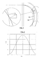
Figure 1 is a depiction of a guide obtained with the technique of the present invention compared to a guide of the current state of the art. -
Figure 2 is a depiction of the cycle followed by the position of the tensioning station when a wheel with 6 teeth is use to tension and turn around a chain. -
Figure 3 shows a chain turned around by a wheel with 6 teeth. -
Figure 4 shows the situation of the guide for obtaining the return guide according to the invention. -
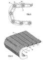
Figure 5 shows the turnaround guide obtained by the process ofFigure 2 . -
Figure 6 shows the pallets turned around by means of the support rollers, with the turnaround guide obtained by the process ofFigure 2 . -
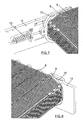
Figure 7 shows the guide profile turning around the pallets with a system allowing the tensioning with respect to the frame. -
Figure 8 shows the guide profile turning around the pallets with a system fixed to the frame. - As shown in
Figure 1 , a guide is achieved with the present invention which is more compact, smoother and more careful with the radial loads to which the turnaround rollers are subjected, reducing the radial force F and F' for one and the same tension T. - To prevent the fluctuations cause by a turnaround by means of wheel with few teeth or with a circular curve (
Figures 2 and3 ), the guide of the present invention achieves the turnaround path for the chain of a moving walkway starting from the situation shown inFigure 4 . - In said
figure, 6 points corresponding to 6 linkages of the traction chain are defined. The initial position of said points depends on two parameters, the distance between the upper pathway and the lower pathway of the traction chain of the walkway (H), the chain pitch (P):




- The path is defined by analyzing a timer interval in which point 1 passes to the position of
point 2,point 2 passes to the position ofpoint 3 and so on until reachingpoint 5 which moves in the negative direction of the x-axis a distance equal to the chain pitch P. - The path of
point 1 during the mentioned time interval (ranging from 0 to 1 according to a parameter t) will be the following.

- Whichever the path of
point 2, this point will be equidistant topoint 1 by a distance equal to the pitch (P), therefore the first equation to obtain the position of 2 will be:
- In addition, an adjustment parameter D will be defined which will be used to adjust the necessary path.
- The second equation will be the equation of a line passing through
point 6 with coordinates X=0; Y=-D and the slope of which varies constantly over time from a vertical position until the slope defined bypoint 6 andpoint 3 in their initial position. It is thus achieved that the final position ofpoint 2 in t=1 is the same as the position in t=0 ofpoint 3. The equation is:
- These two equations define a path between 2 and 3 depending on the distance D which is used as a parameter, which will be called T2(D). Likewise, a path T4 is defined as the symmetrical path of T2 with respect to the X axis, which path will be the one which
point 4 must follow to reachpoint 5. Ifpoint 5 follows a path according to the following equations in the time interval used, a performance of the traction chain moved by a system producing constant speed is simulated.

- Since the path between 4 and 5 is completely defined (T4) and furthermore
point 4 must be at a distance equal to the chain pitch (P) with respect topoint 5, the position of 4 with respect to time is defined by the intersection between the curve called C1 and T4
- Once the paths of 2 and 4 have been defined according to time, the path of
point 3 is defined by the following equations:

- To obtain the optimal curve for the turnaround, iteration must be carried out until finding the value of D making dX2/dY2(t=1) equal to dX3/dY3(t=0), which by symmetry will make dX3/dY3(t=1) equal to dX4/dY4(t=0), and therefore the curve can be derived and is suitable for the rolling of the
rollers 8 of the traction chain therethrough. - Depending on the diameter of each of the rollers following the turnaround path, a series of inner and outer curves will be defined for the rolling of said roller.
-
Figure 5 shows theguide 7 obtained with the process described with reference toFigure 4 , on which therollers 8 driving thepallets 9 are supported. - In a preferred construction, as shown in
Figure 6 thepallets 9 have a pitch equal to the chain pitch and the turnaround is carried out on thesupport wheels 8 of said pallets. - These pallets can be joined to one another to form part of the actual chains.
- The turnaround guides can be fixed (
Figure 8 ) or floating (Figure 7 ) to allow tensioning the traction band if the drive system thereof requires it.


2-3≡f1(D):


5-6:


Claims (10)
- A turnaround curve system for a chain conveyor system, comprising a chain having linear traction which is driven in turnaround sections by means of turnaround guides (7), characterized in that the turnaround guides (7) have a geometry obtained by means of a family of curves corresponding to paths defined by six points (1-6), said six points (1-6) corresponding to six linkage positions of consecutive links of the chain in the turnaround sections, such that:the first path (1-2) between the first point (1) and the second point (2) andthe fifth path (5-6) between the fifth point (1) and the sixth point (6) define a constant linear speed parallel to a straight section of the conveyor system between the turnaround sections;the second path and the fourth path have a certain geometry;the third path is determined by the position of the first, second, fourth and fifth linkages to conserve a distance between links.
- The turnaround curve system of claim 1, characterized in that when each linkage passes to a position occupied by the following linkage in a time interval "t", the paths are defined by six points determined by the following equations:


where:P: chain pitch value;H: distance between a first branch and a second branch of the chain;and the curves of the paths being defined by the following equations:
1-2:

2-3≡f1(D):

3-4:

4-5:


5-6:

assigning to "c" a value comprised between 0 and 1 and where D is a parameter with an optimal value when the following condition is met:

the geometry of the guide is defined by the rolling path of the roller (8) when the linkages follow the defined paths. - The turnaround curve system of any of claims 1-2, characterized in that the turnaround section further comprises a counterguide (10).
- The turnaround curve system of any of claims 1-3, characterized in that the turnaround guide (7) is manufactured by means of a process selected from press forming, machining, deep drawing and combinations thereof.
- The turnaround curve system of any of claims 3-4, characterized in that the turnaround counterguide (10) is manufactured by means of a process selected from press forming, machining, deep drawing and combinations thereof.
- The turnaround curve system of any of claims 3-5, characterized in that the guide (7) and counterguide (10) are fixed to the frame (11).
- The turnaround curve system of any of claims 3-5, characterized in that the guide (7) and counterguide (10) are installed by means of a device (12) to allow tensioning the traction cable with respect to the frame (11).
- The turnaround curve system of any of claims 1-7, characterized in that the turned around traction chain is connected to a conveyor element selected from mechanical stairs and a moving walkway.
- The turnaround curve system of any of claims 1-7, characterized in that the turned around traction chain is connected to a moving walkway comprising a plurality of pallets (9) having a pallet pitch equal to the traction chain pitch P.
- The turnaround curve system of claim 9, characterized in that the pallets (9) joined to one another form the traction chain.
Applications Claiming Priority (1)
| Application Number | Priority Date | Filing Date | Title |
|---|---|---|---|
| ES200702379A ES2294972B1 (en) | 2007-09-05 | 2007-09-05 | TURN CURVE SYSTEM FOR CHAIN TRANSPORTATION SYSTEM. |
Publications (2)
| Publication Number | Publication Date |
|---|---|
| EP2033928A1 true EP2033928A1 (en) | 2009-03-11 |
| EP2033928B1 EP2033928B1 (en) | 2011-08-24 |
Family
ID=39167933
Family Applications (1)
| Application Number | Title | Priority Date | Filing Date |
|---|---|---|---|
| EP08380202A Active EP2033928B1 (en) | 2007-09-05 | 2008-07-07 | Turnaround curve system for a chain conveyor system |
Country Status (5)
| Country | Link |
|---|---|
| US (1) | US8123025B2 (en) |
| EP (1) | EP2033928B1 (en) |
| CN (1) | CN101381052B (en) |
| AT (1) | ATE521565T1 (en) |
| ES (2) | ES2294972B1 (en) |
Cited By (2)
| Publication number | Priority date | Publication date | Assignee | Title |
|---|---|---|---|---|
| US9599201B2 (en) | 2011-05-23 | 2017-03-21 | Otis Elevator Company | Polygon compensation coupling for chain and sprocket driven systems |
| EP3354615A1 (en) | 2017-01-31 | 2018-08-01 | thyssenkrupp Elevator AG | Driving system for driving a conveyer band of a conveyer apparatus |
Families Citing this family (5)
| Publication number | Priority date | Publication date | Assignee | Title |
|---|---|---|---|---|
| ES2367739B1 (en) * | 2011-07-11 | 2012-09-18 | Thyssenkrupp Elevator Innovation Center, S.A. | MOBILE HALL. |
| KR20130049080A (en) * | 2011-11-03 | 2013-05-13 | 삼성디스플레이 주식회사 | Rotating type thin film depositing apparatus and the thin film depositing method using the same |
| US9718646B2 (en) | 2013-04-08 | 2017-08-01 | Otis Elevator Company | Chain drive system with polygon compensation |
| ES2455391B1 (en) * | 2013-09-25 | 2015-03-06 | Thyssenkrupp Elev Innovation | Pallet set for a transport system for passenger / freight transport |
| KR102359925B1 (en) * | 2017-07-12 | 2022-02-07 | 현대자동차 주식회사 | Vehicle body tracking system and method |
Citations (3)
| Publication number | Priority date | Publication date | Assignee | Title |
|---|---|---|---|---|
| GB957272A (en) * | 1961-09-01 | 1964-05-06 | Westinghouse Electric Corp | Moving sidewalk |
| US20030121756A1 (en) * | 2001-12-28 | 2003-07-03 | Copeland George Scott | Pulse-free escalator |
| US20040035676A1 (en) * | 2001-09-26 | 2004-02-26 | Manabu Ogura | Sloped part high-speed escalator |
Family Cites Families (22)
| Publication number | Priority date | Publication date | Assignee | Title |
|---|---|---|---|---|
| US2698078A (en) * | 1950-10-10 | 1954-12-28 | Allied Steel And Conveyors Inc | Nonpulsating and vibrationless conveyer |
| US2905308A (en) * | 1956-06-15 | 1959-09-22 | Westinghouse Electric Corp | Moving stairway |
| US3002604A (en) * | 1957-10-28 | 1961-10-03 | Motomation Inc | Endless chain system |
| BE662898A (en) * | 1964-04-22 | |||
| US3510264A (en) * | 1967-10-12 | 1970-05-05 | James P Sprigg | Apparatus for producing phosphates |
| US3586393A (en) * | 1969-01-23 | 1971-06-22 | William G Myers | Conveyor structure |
| US3915293A (en) * | 1974-02-15 | 1975-10-28 | Fairchild Industries | Article loading apparatus |
| US4130192A (en) * | 1976-12-06 | 1978-12-19 | Westinghouse Electric Corp. | Transportation apparatus |
| US4662502A (en) * | 1983-10-12 | 1987-05-05 | Mitsubishi Denki Kabushiki Kaisha | Curved escalator |
| US5009302A (en) * | 1989-03-27 | 1991-04-23 | Otis Elevator Company | Curved escalator with fixed center constant radius path of travel |
| US4953685A (en) * | 1989-08-10 | 1990-09-04 | Otis Elevator Company | Step chain for curved escalator |
| DE4036667C1 (en) * | 1990-11-17 | 1992-04-16 | Erik Dipl.-Ing. 2870 Delmenhorst De Brunn | |
| US5388685A (en) * | 1994-01-06 | 1995-02-14 | Litton Industrial Automation Systems, Inc. | Endless conveyor |
| US5697486A (en) * | 1994-11-14 | 1997-12-16 | Investio Ag | Device for the guidance of an endless belt for escalators or moving walkways |
| US6196381B1 (en) * | 1996-11-29 | 2001-03-06 | Yamakyu Chain Kabushiki Kaisha | Conveyor chain unit and conveyor chain |
| JP3469445B2 (en) * | 1997-10-15 | 2003-11-25 | 株式会社リコー | Belt driving device and belt fixing device |
| TW405064B (en) * | 1997-11-29 | 2000-09-11 | Fuji Xerox Co Ltd | Image formation apparatus using endless belt |
| JP2003146569A (en) * | 2001-11-05 | 2003-05-21 | Mitsubishi Electric Corp | Inclined high-speed escalator |
| FI20040303L (en) * | 2004-02-26 | 2005-08-27 | Kone Corp | Escalator, ramp or staircase |
| JP4304136B2 (en) * | 2004-03-23 | 2009-07-29 | 東芝エレベータ株式会社 | Conveyor device |
| JP5176223B2 (en) * | 2006-07-04 | 2013-04-03 | インベンテイオ・アクテイエンゲゼルシヤフト | Driving system for passenger transport equipment |
| JP5126880B2 (en) * | 2006-08-31 | 2013-01-23 | 東芝エレベータ株式会社 | Conveyor device |
-
2007
- 2007-09-05 ES ES200702379A patent/ES2294972B1/en not_active Expired - Fee Related
-
2008
- 2008-07-07 EP EP08380202A patent/EP2033928B1/en active Active
- 2008-07-07 AT AT08380202T patent/ATE521565T1/en active
- 2008-07-07 ES ES08380202T patent/ES2372227T3/en active Active
- 2008-09-01 CN CN200810211176.6A patent/CN101381052B/en active Active
- 2008-09-05 US US12/205,343 patent/US8123025B2/en not_active Expired - Fee Related
Patent Citations (4)
| Publication number | Priority date | Publication date | Assignee | Title |
|---|---|---|---|---|
| GB957272A (en) * | 1961-09-01 | 1964-05-06 | Westinghouse Electric Corp | Moving sidewalk |
| US20040035676A1 (en) * | 2001-09-26 | 2004-02-26 | Manabu Ogura | Sloped part high-speed escalator |
| US20030121756A1 (en) * | 2001-12-28 | 2003-07-03 | Copeland George Scott | Pulse-free escalator |
| WO2003066501A1 (en) | 2001-12-28 | 2003-08-14 | Otis Elevator Company | A pulse-free escalator |
Cited By (4)
| Publication number | Priority date | Publication date | Assignee | Title |
|---|---|---|---|---|
| US9599201B2 (en) | 2011-05-23 | 2017-03-21 | Otis Elevator Company | Polygon compensation coupling for chain and sprocket driven systems |
| US10647548B2 (en) | 2011-05-23 | 2020-05-12 | Otis Elevator Company | Polygon compensation coupling for chain and sprocket driven systems |
| EP3354615A1 (en) | 2017-01-31 | 2018-08-01 | thyssenkrupp Elevator AG | Driving system for driving a conveyer band of a conveyer apparatus |
| WO2018141687A1 (en) | 2017-01-31 | 2018-08-09 | Thyssenkrupp Elevator Ag | Driving system for driving a conveyer band of a conveyer apparatus |
Also Published As
| Publication number | Publication date |
|---|---|
| ES2372227T3 (en) | 2012-01-17 |
| ES2294972B1 (en) | 2009-04-01 |
| EP2033928B1 (en) | 2011-08-24 |
| ATE521565T1 (en) | 2011-09-15 |
| CN101381052A (en) | 2009-03-11 |
| CN101381052B (en) | 2013-06-19 |
| US20090065328A1 (en) | 2009-03-12 |
| US8123025B2 (en) | 2012-02-28 |
| ES2294972A1 (en) | 2008-04-01 |
Similar Documents
| Publication | Publication Date | Title |
|---|---|---|
| EP2033928B1 (en) | Turnaround curve system for a chain conveyor system | |
| JP5176223B2 (en) | Driving system for passenger transport equipment | |
| EP3257804B1 (en) | Belt-driven people conveyor | |
| EP2085643B1 (en) | Method and apparatus for pre-tensioning a power transmission chain | |
| CN102123933B (en) | People mover and method in the use of a people mover | |
| JP2009103150A (en) | Power transmission chain and power transmission device | |
| JP2002227948A (en) | Variator | |
| EP2938567A1 (en) | Conveyor system for the transport of passengers/goods | |
| EP2872434B1 (en) | Drive system for passenger conveyor | |
| DE60205451D1 (en) | BELT ELEMENT FOR A DRIVE BELT FOR STEADLY CONTROLLED GEARBOX | |
| US20020046917A1 (en) | Flexible belt, conveyor system using flexible belt and escalator system using flexible belt | |
| US9050649B2 (en) | Assembly method and assembly equipment for power transmission chain | |
| US6659897B2 (en) | Chain drive assembly | |
| US8182384B2 (en) | Power transmission chain and power transmission apparatus | |
| JP2006512262A (en) | Arrangement of drive modules for passenger transporters | |
| JP2009154164A (en) | Power transmission chain manufacturing method and manufacturing apparatus | |
| JP2011069410A (en) | Power transmission device | |
| JP5614019B2 (en) | Power transmission device | |
| JP2005114133A (en) | Power transmission chain and power transmission unit using the same | |
| EP3569554A1 (en) | Drive system for a people conveyor | |
| HK1159589B (en) | People mover, and method in the use of a people mover | |
| JPH09169484A (en) | Acceleration / deceleration type passenger conveyor drive | |
| HK1121728B (en) | Travelator and method for controlling the operation of a travelator | |
| KR20070018861A (en) | Conveyor device |
Legal Events
| Date | Code | Title | Description |
|---|---|---|---|
| PUAI | Public reference made under article 153(3) epc to a published international application that has entered the european phase |
Free format text: ORIGINAL CODE: 0009012 |
|
| AK | Designated contracting states |
Kind code of ref document: A1 Designated state(s): AT BE BG CH CY CZ DE DK EE ES FI FR GB GR HR HU IE IS IT LI LT LU LV MC MT NL NO PL PT RO SE SI SK TR |
|
| AX | Request for extension of the european patent |
Extension state: AL BA MK RS |
|
| 17P | Request for examination filed |
Effective date: 20090429 |
|
| 17Q | First examination report despatched |
Effective date: 20090622 |
|
| AKX | Designation fees paid |
Designated state(s): AT BE BG CH CY CZ DE DK EE ES FI FR GB GR HR HU IE IS IT LI LT LU LV MC MT NL NO PL PT RO SE SI SK TR |
|
| GRAP | Despatch of communication of intention to grant a patent |
Free format text: ORIGINAL CODE: EPIDOSNIGR1 |
|
| GRAS | Grant fee paid |
Free format text: ORIGINAL CODE: EPIDOSNIGR3 |
|
| GRAA | (expected) grant |
Free format text: ORIGINAL CODE: 0009210 |
|
| RAP1 | Party data changed (applicant data changed or rights of an application transferred) |
Owner name: THYSSENKRUPP ELEVATOR (ES/PBB) LTD. Owner name: THYSSENKRUPP ELEVATOR INNOVATION CENTER S.A. |
|
| RTI1 | Title (correction) |
Free format text: TURNAROUND CURVE SYSTEM FOR A CHAIN CONVEYOR SYSTEM |
|
| AK | Designated contracting states |
Kind code of ref document: B1 Designated state(s): AT BE BG CH CY CZ DE DK EE ES FI FR GB GR HR HU IE IS IT LI LT LU LV MC MT NL NO PL PT RO SE SI SK TR |
|
| REG | Reference to a national code |
Ref country code: GB Ref legal event code: FG4D |
|
| REG | Reference to a national code |
Ref country code: CH Ref legal event code: EP |
|
| REG | Reference to a national code |
Ref country code: IE Ref legal event code: FG4D |
|
| REG | Reference to a national code |
Ref country code: DE Ref legal event code: R096 Ref document number: 602008009090 Country of ref document: DE Effective date: 20111103 |
|
| REG | Reference to a national code |
Ref country code: CH Ref legal event code: NV Representative=s name: HEPP WENGER RYFFEL AG |
|
| REG | Reference to a national code |
Ref country code: NL Ref legal event code: T3 |
|
| REG | Reference to a national code |
Ref country code: ES Ref legal event code: FG2A Ref document number: 2372227 Country of ref document: ES Kind code of ref document: T3 Effective date: 20120117 |
|
| LTIE | Lt: invalidation of european patent or patent extension |
Effective date: 20110824 |
|
| PG25 | Lapsed in a contracting state [announced via postgrant information from national office to epo] |
Ref country code: LT Free format text: LAPSE BECAUSE OF FAILURE TO SUBMIT A TRANSLATION OF THE DESCRIPTION OR TO PAY THE FEE WITHIN THE PRESCRIBED TIME-LIMIT Effective date: 20110824 Ref country code: PT Free format text: LAPSE BECAUSE OF FAILURE TO SUBMIT A TRANSLATION OF THE DESCRIPTION OR TO PAY THE FEE WITHIN THE PRESCRIBED TIME-LIMIT Effective date: 20111226 Ref country code: SE Free format text: LAPSE BECAUSE OF FAILURE TO SUBMIT A TRANSLATION OF THE DESCRIPTION OR TO PAY THE FEE WITHIN THE PRESCRIBED TIME-LIMIT Effective date: 20110824 Ref country code: NO Free format text: LAPSE BECAUSE OF FAILURE TO SUBMIT A TRANSLATION OF THE DESCRIPTION OR TO PAY THE FEE WITHIN THE PRESCRIBED TIME-LIMIT Effective date: 20111124 Ref country code: IS Free format text: LAPSE BECAUSE OF FAILURE TO SUBMIT A TRANSLATION OF THE DESCRIPTION OR TO PAY THE FEE WITHIN THE PRESCRIBED TIME-LIMIT Effective date: 20111224 Ref country code: HR Free format text: LAPSE BECAUSE OF FAILURE TO SUBMIT A TRANSLATION OF THE DESCRIPTION OR TO PAY THE FEE WITHIN THE PRESCRIBED TIME-LIMIT Effective date: 20110824 |
|
| PG25 | Lapsed in a contracting state [announced via postgrant information from national office to epo] |
Ref country code: CY Free format text: LAPSE BECAUSE OF FAILURE TO SUBMIT A TRANSLATION OF THE DESCRIPTION OR TO PAY THE FEE WITHIN THE PRESCRIBED TIME-LIMIT Effective date: 20110824 Ref country code: LV Free format text: LAPSE BECAUSE OF FAILURE TO SUBMIT A TRANSLATION OF THE DESCRIPTION OR TO PAY THE FEE WITHIN THE PRESCRIBED TIME-LIMIT Effective date: 20110824 Ref country code: PL Free format text: LAPSE BECAUSE OF FAILURE TO SUBMIT A TRANSLATION OF THE DESCRIPTION OR TO PAY THE FEE WITHIN THE PRESCRIBED TIME-LIMIT Effective date: 20110824 Ref country code: SI Free format text: LAPSE BECAUSE OF FAILURE TO SUBMIT A TRANSLATION OF THE DESCRIPTION OR TO PAY THE FEE WITHIN THE PRESCRIBED TIME-LIMIT Effective date: 20110824 Ref country code: GR Free format text: LAPSE BECAUSE OF FAILURE TO SUBMIT A TRANSLATION OF THE DESCRIPTION OR TO PAY THE FEE WITHIN THE PRESCRIBED TIME-LIMIT Effective date: 20111125 |
|
| PG25 | Lapsed in a contracting state [announced via postgrant information from national office to epo] |
Ref country code: BE Free format text: LAPSE BECAUSE OF FAILURE TO SUBMIT A TRANSLATION OF THE DESCRIPTION OR TO PAY THE FEE WITHIN THE PRESCRIBED TIME-LIMIT Effective date: 20110824 |
|
| PG25 | Lapsed in a contracting state [announced via postgrant information from national office to epo] |
Ref country code: CZ Free format text: LAPSE BECAUSE OF FAILURE TO SUBMIT A TRANSLATION OF THE DESCRIPTION OR TO PAY THE FEE WITHIN THE PRESCRIBED TIME-LIMIT Effective date: 20110824 Ref country code: SK Free format text: LAPSE BECAUSE OF FAILURE TO SUBMIT A TRANSLATION OF THE DESCRIPTION OR TO PAY THE FEE WITHIN THE PRESCRIBED TIME-LIMIT Effective date: 20110824 |
|
| PG25 | Lapsed in a contracting state [announced via postgrant information from national office to epo] |
Ref country code: EE Free format text: LAPSE BECAUSE OF FAILURE TO SUBMIT A TRANSLATION OF THE DESCRIPTION OR TO PAY THE FEE WITHIN THE PRESCRIBED TIME-LIMIT Effective date: 20110824 Ref country code: RO Free format text: LAPSE BECAUSE OF FAILURE TO SUBMIT A TRANSLATION OF THE DESCRIPTION OR TO PAY THE FEE WITHIN THE PRESCRIBED TIME-LIMIT Effective date: 20110824 |
|
| PG25 | Lapsed in a contracting state [announced via postgrant information from national office to epo] |
Ref country code: DK Free format text: LAPSE BECAUSE OF FAILURE TO SUBMIT A TRANSLATION OF THE DESCRIPTION OR TO PAY THE FEE WITHIN THE PRESCRIBED TIME-LIMIT Effective date: 20110824 |
|
| PLBE | No opposition filed within time limit |
Free format text: ORIGINAL CODE: 0009261 |
|
| STAA | Information on the status of an ep patent application or granted ep patent |
Free format text: STATUS: NO OPPOSITION FILED WITHIN TIME LIMIT |
|
| 26N | No opposition filed |
Effective date: 20120525 |
|
| REG | Reference to a national code |
Ref country code: DE Ref legal event code: R097 Ref document number: 602008009090 Country of ref document: DE Effective date: 20120525 |
|
| PG25 | Lapsed in a contracting state [announced via postgrant information from national office to epo] |
Ref country code: MC Free format text: LAPSE BECAUSE OF NON-PAYMENT OF DUE FEES Effective date: 20120731 |
|
| REG | Reference to a national code |
Ref country code: IE Ref legal event code: MM4A |
|
| PG25 | Lapsed in a contracting state [announced via postgrant information from national office to epo] |
Ref country code: BG Free format text: LAPSE BECAUSE OF FAILURE TO SUBMIT A TRANSLATION OF THE DESCRIPTION OR TO PAY THE FEE WITHIN THE PRESCRIBED TIME-LIMIT Effective date: 20111124 |
|
| PG25 | Lapsed in a contracting state [announced via postgrant information from national office to epo] |
Ref country code: MT Free format text: LAPSE BECAUSE OF FAILURE TO SUBMIT A TRANSLATION OF THE DESCRIPTION OR TO PAY THE FEE WITHIN THE PRESCRIBED TIME-LIMIT Effective date: 20110824 Ref country code: IE Free format text: LAPSE BECAUSE OF NON-PAYMENT OF DUE FEES Effective date: 20120707 |
|
| PG25 | Lapsed in a contracting state [announced via postgrant information from national office to epo] |
Ref country code: TR Free format text: LAPSE BECAUSE OF FAILURE TO SUBMIT A TRANSLATION OF THE DESCRIPTION OR TO PAY THE FEE WITHIN THE PRESCRIBED TIME-LIMIT Effective date: 20110824 |
|
| PG25 | Lapsed in a contracting state [announced via postgrant information from national office to epo] |
Ref country code: LU Free format text: LAPSE BECAUSE OF NON-PAYMENT OF DUE FEES Effective date: 20120707 |
|
| PG25 | Lapsed in a contracting state [announced via postgrant information from national office to epo] |
Ref country code: HU Free format text: LAPSE BECAUSE OF FAILURE TO SUBMIT A TRANSLATION OF THE DESCRIPTION OR TO PAY THE FEE WITHIN THE PRESCRIBED TIME-LIMIT Effective date: 20080707 |
|
| REG | Reference to a national code |
Ref country code: FR Ref legal event code: PLFP Year of fee payment: 9 |
|
| REG | Reference to a national code |
Ref country code: FR Ref legal event code: PLFP Year of fee payment: 10 |
|
| PGFP | Annual fee paid to national office [announced via postgrant information from national office to epo] |
Ref country code: NL Payment date: 20170719 Year of fee payment: 10 |
|
| PGFP | Annual fee paid to national office [announced via postgrant information from national office to epo] |
Ref country code: FR Payment date: 20170726 Year of fee payment: 10 Ref country code: GB Payment date: 20170719 Year of fee payment: 10 |
|
| REG | Reference to a national code |
Ref country code: DE Ref legal event code: R083 Ref document number: 602008009090 Country of ref document: DE |
|
| REG | Reference to a national code |
Ref country code: NL Ref legal event code: MM Effective date: 20180801 |
|
| GBPC | Gb: european patent ceased through non-payment of renewal fee |
Effective date: 20180707 |
|
| PG25 | Lapsed in a contracting state [announced via postgrant information from national office to epo] |
Ref country code: GB Free format text: LAPSE BECAUSE OF NON-PAYMENT OF DUE FEES Effective date: 20180707 Ref country code: FR Free format text: LAPSE BECAUSE OF NON-PAYMENT OF DUE FEES Effective date: 20180731 |
|
| PG25 | Lapsed in a contracting state [announced via postgrant information from national office to epo] |
Ref country code: NL Free format text: LAPSE BECAUSE OF NON-PAYMENT OF DUE FEES Effective date: 20180801 |
|
| PG25 | Lapsed in a contracting state [announced via postgrant information from national office to epo] |
Ref country code: IT Free format text: LAPSE BECAUSE OF NON-PAYMENT OF DUE FEES Effective date: 20180707 |
|
| PGFP | Annual fee paid to national office [announced via postgrant information from national office to epo] |
Ref country code: FI Payment date: 20210722 Year of fee payment: 14 |
|
| PGFP | Annual fee paid to national office [announced via postgrant information from national office to epo] |
Ref country code: CH Payment date: 20210721 Year of fee payment: 14 |
|
| REG | Reference to a national code |
Ref country code: CH Ref legal event code: PL |
|
| PG25 | Lapsed in a contracting state [announced via postgrant information from national office to epo] |
Ref country code: LI Free format text: LAPSE BECAUSE OF NON-PAYMENT OF DUE FEES Effective date: 20220731 Ref country code: FI Free format text: LAPSE BECAUSE OF NON-PAYMENT OF DUE FEES Effective date: 20220707 Ref country code: CH Free format text: LAPSE BECAUSE OF NON-PAYMENT OF DUE FEES Effective date: 20220731 |
|
| P01 | Opt-out of the competence of the unified patent court (upc) registered |
Effective date: 20230526 |
|
| PGFP | Annual fee paid to national office [announced via postgrant information from national office to epo] |
Ref country code: ES Payment date: 20250826 Year of fee payment: 18 |
|
| PGFP | Annual fee paid to national office [announced via postgrant information from national office to epo] |
Ref country code: DE Payment date: 20250722 Year of fee payment: 18 |
|
| PGFP | Annual fee paid to national office [announced via postgrant information from national office to epo] |
Ref country code: AT Payment date: 20250722 Year of fee payment: 18 |