EP3354613A1 - Elevator brake wedge - Google Patents
Elevator brake wedge Download PDFInfo
- Publication number
- EP3354613A1 EP3354613A1 EP18153153.4A EP18153153A EP3354613A1 EP 3354613 A1 EP3354613 A1 EP 3354613A1 EP 18153153 A EP18153153 A EP 18153153A EP 3354613 A1 EP3354613 A1 EP 3354613A1
- Authority
- EP
- European Patent Office
- Prior art keywords
- low
- friction film
- major surface
- grooves
- minor
- Prior art date
- Legal status (The legal status is an assumption and is not a legal conclusion. Google has not performed a legal analysis and makes no representation as to the accuracy of the status listed.)
- Granted
Links
Images
Classifications
-
- B—PERFORMING OPERATIONS; TRANSPORTING
- B66—HOISTING; LIFTING; HAULING
- B66B—ELEVATORS; ESCALATORS OR MOVING WALKWAYS
- B66B5/00—Applications of checking, fault-correcting, or safety devices in elevators
- B66B5/02—Applications of checking, fault-correcting, or safety devices in elevators responsive to abnormal operating conditions
- B66B5/16—Braking or catch devices operating between cars, cages, or skips and fixed guide elements or surfaces in hoistway or well
- B66B5/18—Braking or catch devices operating between cars, cages, or skips and fixed guide elements or surfaces in hoistway or well and applying frictional retarding forces
- B66B5/22—Braking or catch devices operating between cars, cages, or skips and fixed guide elements or surfaces in hoistway or well and applying frictional retarding forces by means of linearly-movable wedges
-
- B—PERFORMING OPERATIONS; TRANSPORTING
- B66—HOISTING; LIFTING; HAULING
- B66B—ELEVATORS; ESCALATORS OR MOVING WALKWAYS
- B66B5/00—Applications of checking, fault-correcting, or safety devices in elevators
- B66B5/02—Applications of checking, fault-correcting, or safety devices in elevators responsive to abnormal operating conditions
- B66B5/16—Braking or catch devices operating between cars, cages, or skips and fixed guide elements or surfaces in hoistway or well
- B66B5/18—Braking or catch devices operating between cars, cages, or skips and fixed guide elements or surfaces in hoistway or well and applying frictional retarding forces
-
- B—PERFORMING OPERATIONS; TRANSPORTING
- B22—CASTING; POWDER METALLURGY
- B22D—CASTING OF METALS; CASTING OF OTHER SUBSTANCES BY THE SAME PROCESSES OR DEVICES
- B22D25/00—Special casting characterised by the nature of the product
- B22D25/02—Special casting characterised by the nature of the product by its peculiarity of shape; of works of art
-
- B—PERFORMING OPERATIONS; TRANSPORTING
- B29—WORKING OF PLASTICS; WORKING OF SUBSTANCES IN A PLASTIC STATE IN GENERAL
- B29C—SHAPING OR JOINING OF PLASTICS; SHAPING OF MATERIAL IN A PLASTIC STATE, NOT OTHERWISE PROVIDED FOR; AFTER-TREATMENT OF THE SHAPED PRODUCTS, e.g. REPAIRING
- B29C43/00—Compression moulding, i.e. applying external pressure to flow the moulding material; Apparatus therefor
- B29C43/02—Compression moulding, i.e. applying external pressure to flow the moulding material; Apparatus therefor of articles of definite length, i.e. discrete articles
- B29C43/18—Compression moulding, i.e. applying external pressure to flow the moulding material; Apparatus therefor of articles of definite length, i.e. discrete articles incorporating preformed parts or layers, e.g. compression moulding around inserts or for coating articles
-
- B—PERFORMING OPERATIONS; TRANSPORTING
- B29—WORKING OF PLASTICS; WORKING OF SUBSTANCES IN A PLASTIC STATE IN GENERAL
- B29C—SHAPING OR JOINING OF PLASTICS; SHAPING OF MATERIAL IN A PLASTIC STATE, NOT OTHERWISE PROVIDED FOR; AFTER-TREATMENT OF THE SHAPED PRODUCTS, e.g. REPAIRING
- B29C45/00—Injection moulding, i.e. forcing the required volume of moulding material through a nozzle into a closed mould; Apparatus therefor
- B29C45/14—Injection moulding, i.e. forcing the required volume of moulding material through a nozzle into a closed mould; Apparatus therefor incorporating preformed parts or layers, e.g. injection moulding around inserts or for coating articles
-
- B—PERFORMING OPERATIONS; TRANSPORTING
- B33—ADDITIVE MANUFACTURING TECHNOLOGY
- B33Y—ADDITIVE MANUFACTURING, i.e. MANUFACTURING OF THREE-DIMENSIONAL [3D] OBJECTS BY ADDITIVE DEPOSITION, ADDITIVE AGGLOMERATION OR ADDITIVE LAYERING, e.g. BY 3D PRINTING, STEREOLITHOGRAPHY OR SELECTIVE LASER SINTERING
- B33Y10/00—Processes of additive manufacturing
-
- B—PERFORMING OPERATIONS; TRANSPORTING
- B33—ADDITIVE MANUFACTURING TECHNOLOGY
- B33Y—ADDITIVE MANUFACTURING, i.e. MANUFACTURING OF THREE-DIMENSIONAL [3D] OBJECTS BY ADDITIVE DEPOSITION, ADDITIVE AGGLOMERATION OR ADDITIVE LAYERING, e.g. BY 3D PRINTING, STEREOLITHOGRAPHY OR SELECTIVE LASER SINTERING
- B33Y80/00—Products made by additive manufacturing
-
- B—PERFORMING OPERATIONS; TRANSPORTING
- B29—WORKING OF PLASTICS; WORKING OF SUBSTANCES IN A PLASTIC STATE IN GENERAL
- B29K—INDEXING SCHEME ASSOCIATED WITH SUBCLASSES B29B, B29C OR B29D, RELATING TO MOULDING MATERIALS OR TO MATERIALS FOR MOULDS, REINFORCEMENTS, FILLERS OR PREFORMED PARTS, e.g. INSERTS
- B29K2705/00—Use of metals, their alloys or their compounds, for preformed parts, e.g. for inserts
-
- B—PERFORMING OPERATIONS; TRANSPORTING
- B29—WORKING OF PLASTICS; WORKING OF SUBSTANCES IN A PLASTIC STATE IN GENERAL
- B29L—INDEXING SCHEME ASSOCIATED WITH SUBCLASS B29C, RELATING TO PARTICULAR ARTICLES
- B29L2031/00—Other particular articles
- B29L2031/16—Frictional elements, e.g. brake or clutch linings
Definitions
- the following description relates to elevator brakes and, more particularly, to elevator brakes with elevator brake wedges having low-friction film supporting grooves.
- Safety assemblies for certain elevators have a passive part and an active part that moves within the passive part.
- the active part can be provided as wedges that move between non-braking and braking positions relative to a central rail and laterally positioned sliding guides.
- the wedges need to be self-engaging and capable of disengagement and require a low friction guiding surface to facilitate movement along sliding guide surfaces to guarantee their respective engagement and disengagement with the rail when conditions dictate that the safety assembly be engaged and then disengaged.
- the guiding surfaces of the wedges can have reliability and durability issues due to mechanical wear in particular without the introduction of preferential lower friction features to mitigate such conditions.
- an industry solution has been to introduce a linear roller bearing assembly between the guiding surfaces of the wedges and sliding guides, the bearings are generally overly thick, complex and expensive.
- Another alternative has been to use a thin, low friction element (film) that is adhesive bonded to the wedge to provide the necessary low friction guiding surfaces of the wedge adjacent to the sliding guides. Durability of such films remains problematic though because the materials of the low friction guiding surfaces are inherently difficult to bond to the wedges or retain their bond strength during usage of the safety assemblies.
- an elevator brake wedge includes an elongate body having first and second generally opposed major surfaces and first and second generally opposed minor surfaces.
- the second minor surface has a greater length than the first minor surface.
- Each of the first and second major surfaces extends between corresponding first and second ends of the first and second minor surfaces, respectively.
- the second major surface defines low-friction film securing grooves extending from a plane of the second major surface into the elongate body.
- the elongate body includes metallic materials or metallic alloys and the low-friction film securing grooves are receptive of low-friction film handles.
- a material of the second major surface directly and non-adhesively contacts a material of a low-friction film.
- each of the low-friction film securing grooves has an elongate shape.
- a longitudinal axis of each of the low-friction film securing grooves is acutely angled relative to the plane of the second major surface and a corner of each of the low-friction film securing grooves is rounded.
- each of the low-friction film securing grooves has a V-shape.
- each of the low-friction film securing grooves has a tongue-in-flap shape.
- each of the low-friction film securing grooves has a ball-in-shoulder shape.
- an elevator brake in accordance with another aspect of the disclosure, includes first and second sliding guides supportable in a body on either side of a rail, first and second brake wedges and a low-friction film.
- the first and second brake wedges are configured to assume respective non-braking and braking positions in the body between the sides of the rail and the first and second sliding guides, respectively.
- Each of the first and second brake wedges includes a first major surface for engagement with the rail, a second major surface generally opposite the first major surface and formed to define grooves and a low-friction film.
- the low-friction film has handles which are receivable in the grooves to support the low-friction film at the second major surface for engagement with a corresponding one of the first and second sliding guides.
- each of the first and second brake wedges further includes a first minor surface and a second minor surface generally opposed to and having a greater length than the first minor surface and the grooves extend from a plane of the second major surface toward a plane of the first major surface.
- the first and second brake wedges include metallic materials or metallic alloys and the low-friction film includes at least one of filled or unfilled thermoplastic materials, filled or unfilled polymers, filled or unfilled thermoplastics and/or thermoset or epoxy materials with low friction additives.
- a material of the second major surface directly and non-adhesively contacts a material of the low-friction film.
- each of the grooves has an elongate shape and a longitudinal axis of each of the grooves is acutely angled relative to the plane of the second major surface and a corner of each of the grooves is rounded.
- each of the grooves has a V-shape.
- each of the grooves has a tongue-in-flap shape.
- each of the grooves has a ball-in-shoulder shape.
- a method of forming an elevator brake wedge includes forming an elongate body having first and second generally opposed major surfaces and first and second generally opposed minor surfaces such that the second minor surface has a greater length than the first minor surface, each of the first and second major surfaces extends between corresponding first and second ends of the first and second minor surfaces, respectively, and the second major surface defines low-friction film securing grooves extending from a plane of the second major surface into the elongate body.
- the forming includes a forming of the elongate body by at least one of casting and printing.
- the forming includes a forming of the low-friction film securing grooves by machining.
- the method includes at least one of injection molding, compression molding, hot melting, and net-shaping of a low-friction film supportable by the low-friction film securing grooves at the second major surface.
- an elevator brake and an elevator brake wedge are provided and do not rely on adhesion to keep low friction materials in place. Instead, the elevator brake and the elevator brake wedge make use of inherent compression forces generated from safety gear engagement to isolate the low friction surfaces. This is achieved by forming grooves in the backsides of elevator brake safety wedges and by pressing or injecting low friction material into the grooves to form pads or films that can be replaced as needed. When the elevator brake safety wedges are engaged, the compression forces press the low friction film into the grooves and thus keep the low friction film stationary while allowing the elevator brake safety wedges to move into place as required for safety engagement and disengagement.
- an elevator brake 10 is provided.
- the elevator brake includes a guide rail 11 and a brake element 12.
- the guide rail 11 has a cross beam 110 and a main beam 111 extending normally from a central portion of the cross beam 110.
- the brake element 12 is configured to be capable of self-engagement and disengagement with respect to opposite sides of the main beam 111 of the guide rail 11.
- the brake element 12 thus includes a support structure body 120, which is formed to define a track along which the main beam 111 can travel, an actuator 121, first and second sliding guides 122 and 123, first and second safety brake wedges 124 and 125.
- the support structure body 120 includes a base part 1201 and sidewalls 1202 extending from opposite sides of the base part 1201.
- the base part 1201 is generally tapered along a longitudinal axis thereof such that the sidewalls 1202 correspondingly taper toward each other.
- the first and second sliding guides 122 and 123 are supportively disposed along the sidewalls 1202 on either side of the guide rail 11, respectively, and are thus tapered toward each other at a same angle as the sidewalls 1202.
- the first and second sliding guides 122 and 123 may be formed, for example, of metallic materials or metallic alloys.
- the first and second safety brake wedges 124 and 125 are partially controllable by the actuator 121 and configured to assume respective non-braking and braking positions in the support structure body 120 between the sides of the guide rail 11 and the first and second sliding guides 122 and 123, respectively.
- the respective non-braking positions of the first and second safety brake wedges 124 and 125 are characterized in that the first and second safety brake wedges 124 and 125 are disposed at or proximate to a wide end of the support structure body 120 whereas the respective braking positions of the first and second safety brake wedges 124 and 125 are characterized in that the first and second safety brake wedges 124 and 125 are disposed at or proximate to a narrow end of the support body.
- the actuator 121 moves the first and second safety brake wedges 124 and 125 from their respective non-braking positions and toward their respective braking positions. Subsequently, once the first and second safety brake wedges 124 and 125 begin to engage with the guide rail 11 and the first and second sliding guides 122 and 123 as they travel towards their respective braking positions, the first and second safety brake wedges 124 and 125 self-engage with the guide rail 11 and the first and second sliding guides 122 and 123.
- each of the first and second safety brake wedges 124 and 125 includes an elongate body 40.
- the elongate body 40 has a first major surface 41, a second major surface 42 that is generally opposed to the first major surface 41, a first minor surface 43 and a second minor surface 44 that is generally opposed to the first minor surface 43.
- the second minor surface 44 has a greater length than the first minor surface 43 and each of the first and second major surfaces 41 and 42 extend between corresponding first and second ends of the first and second minor surfaces 43 and 44, respectively.
- the first and second major surfaces 41 and 42 taper towards one another with decreasing distance toward the first minor surface 43.
- the first major surface 41 is substantially planarized and flat for smooth engagement with the corresponding side of the guide rail 11.
- the second major surface 42 is formed to define low-friction film securing grooves 45.
- the low-friction film securing grooves 45 extend from a plane P2 of the second major surface 42 into the elongate body 40 and toward a plane P1 of the first major surface 41.
- each of the first and second safety brake wedges 124 and 125 also include a low-friction film 50.
- the low-friction film 50 is formed to include a film portion 51 and handles 52 protruding from the film portion 51.
- the handles 52 are receivable in the low-friction film securing grooves 45 such that the low-friction film 50 is supportively disposed at the second major surface 42 for engagement with a corresponding one of the first and second sliding guides 122 and 123.
- the elongate body 40 includes or is formed of metallic materials or metallic alloys.
- the low-friction film 50 includes or is formed of at least one of thermoplastic and optionally any one or more of filled or unfilled thermoplastic materials, filled or unfilled polymers, filled or unfilled thermoplastics and/or thermoset or epoxy materials with low friction additives.
- the polymers may include, but are not limited to, fluoropolymers such as polyvinyl ethylene, polyvinylidene fluoride, ethylene tetrafluoroethylene polymers, polyethylene chlorotrifluoroethylene, etc.
- the fillers may include, but are not limited to, glass, carbon, graphite or other similar materials.
- the material(s) of the low-friction film 50 can be inherently difficult to bond to the material(s) of the elongate body 40.
- the low-friction film securing grooves 45 are provided to receive the handles 52 such that the low-friction film 50 can be held in place. That is, in accordance with further embodiments, material(s) of the second major surface 42 directly and substantially non-adhesively contact material(s) of the low-friction film 50.
- each of the low-friction film securing grooves 45 may have an elongate cross-sectional shape 501 that traverses an entire depth-wise thickness of the elongate body 40.
- a longitudinal axis of each of the low-friction film securing grooves 45 is acutely angled relative to the plane P2 of the second major surface 42 and a corner 450 of each of the low-friction film securing grooves 45 can be rounded so as to avoid chipping or potential damages to the low-friction film 50.
- each of the low-friction film securing grooves 45 may have a V-shape 502 in cross-section (see FIG. 7 ), a tongue-in-flap shape 503 in cross-section (see FIG. 8 ) or a ball-in-shoulder shape 505 in cross-section (see FIG. 9 ).
- the shape and orientation of the low-friction film securing grooves 45 will drive the handles 52 to assume complementary shapes with complementary orientations and will lead to an increase in compression forces being applied to the handles 52 as the first and second safety wedges 124 and 125 are brought into their respective braking positions.
- This increased compression will in turn lead to the low-friction films 50 being secured in place at the second major surfaces 42 with increasing security and reliability until the respective braking positions are attained and without introducing durability issues typically associated with adhesion bonding.
- a method of forming a safety brake wedge for an elevator includes forming the above-described elongate body 40 to have the first and second generally opposed major surfaces 41 and 42 and to have the first and second generally opposed minor surfaces 43 and 44.
- the forming is conducted such that the second minor surface 44 has a greater length than the first minor surface 43, such that each of the first and second major surfaces 41 and 42 extends between corresponding first and second ends of the first and second minor surfaces 43 and 44, respectively, and such that the second major surface 42 defines the above-described low-friction film securing grooves 45.
- the elongate body 40 may be formed by at least one of casting and printing processes, for example.
- the forming of the low-friction film securing grooves 45 can be conducted as part of the casting or printing of the elongate body 40 as a whole or by machining once the elongate body 40 is already formed.
- the above-described low-friction film 50 can be formed, for example, by injection molding, compression molding, hot melting or net-shaping of low-friction film material at the second major surface 42 so that the low-friction film material charges into the low-friction film securing grooves 45 to form the handles 52 while the remainder connects the handles 52 with each other as the film portion 51.
Landscapes
- Engineering & Computer Science (AREA)
- Mechanical Engineering (AREA)
- Manufacturing & Machinery (AREA)
- Chemical & Material Sciences (AREA)
- Materials Engineering (AREA)
- Maintenance And Inspection Apparatuses For Elevators (AREA)
- Braking Arrangements (AREA)
Abstract
Description
- The following description relates to elevator brakes and, more particularly, to elevator brakes with elevator brake wedges having low-friction film supporting grooves.
- Safety assemblies for certain elevators have a passive part and an active part that moves within the passive part. In some cases, the active part can be provided as wedges that move between non-braking and braking positions relative to a central rail and laterally positioned sliding guides. In order to operate correctly, the wedges need to be self-engaging and capable of disengagement and require a low friction guiding surface to facilitate movement along sliding guide surfaces to guarantee their respective engagement and disengagement with the rail when conditions dictate that the safety assembly be engaged and then disengaged.
- Over time, however, it has been seen that the guiding surfaces of the wedges can have reliability and durability issues due to mechanical wear in particular without the introduction of preferential lower friction features to mitigate such conditions. While an industry solution has been to introduce a linear roller bearing assembly between the guiding surfaces of the wedges and sliding guides, the bearings are generally overly thick, complex and expensive. Another alternative has been to use a thin, low friction element (film) that is adhesive bonded to the wedge to provide the necessary low friction guiding surfaces of the wedge adjacent to the sliding guides. Durability of such films remains problematic though because the materials of the low friction guiding surfaces are inherently difficult to bond to the wedges or retain their bond strength during usage of the safety assemblies.
- According to one aspect of the disclosure, an elevator brake wedge is provided and includes an elongate body having first and second generally opposed major surfaces and first and second generally opposed minor surfaces. The second minor surface has a greater length than the first minor surface. Each of the first and second major surfaces extends between corresponding first and second ends of the first and second minor surfaces, respectively. The second major surface defines low-friction film securing grooves extending from a plane of the second major surface into the elongate body.
- In accordance with additional or alternative embodiments, the elongate body includes metallic materials or metallic alloys and the low-friction film securing grooves are receptive of low-friction film handles.
- In accordance with additional or alternative embodiments, a material of the second major surface directly and non-adhesively contacts a material of a low-friction film.
- In accordance with additional or alternative embodiments, each of the low-friction film securing grooves has an elongate shape.
- In accordance with additional or alternative embodiments, a longitudinal axis of each of the low-friction film securing grooves is acutely angled relative to the plane of the second major surface and a corner of each of the low-friction film securing grooves is rounded.
- In accordance with additional or alternative embodiments, each of the low-friction film securing grooves has a V-shape.
- In accordance with additional or alternative embodiments, each of the low-friction film securing grooves has a tongue-in-flap shape.
- In accordance with additional or alternative embodiments, each of the low-friction film securing grooves has a ball-in-shoulder shape.
- In accordance with another aspect of the disclosure, an elevator brake is provided and includes first and second sliding guides supportable in a body on either side of a rail, first and second brake wedges and a low-friction film. The first and second brake wedges are configured to assume respective non-braking and braking positions in the body between the sides of the rail and the first and second sliding guides, respectively. Each of the first and second brake wedges includes a first major surface for engagement with the rail, a second major surface generally opposite the first major surface and formed to define grooves and a low-friction film. The low-friction film has handles which are receivable in the grooves to support the low-friction film at the second major surface for engagement with a corresponding one of the first and second sliding guides.
- In accordance with additional or alternative embodiments, each of the first and second brake wedges further includes a first minor surface and a second minor surface generally opposed to and having a greater length than the first minor surface and the grooves extend from a plane of the second major surface toward a plane of the first major surface.
- In accordance with additional or alternative embodiments, the first and second brake wedges include metallic materials or metallic alloys and the low-friction film includes at least one of filled or unfilled thermoplastic materials, filled or unfilled polymers, filled or unfilled thermoplastics and/or thermoset or epoxy materials with low friction additives.
- In accordance with additional or alternative embodiments, a material of the second major surface directly and non-adhesively contacts a material of the low-friction film.
- In accordance with additional or alternative embodiments, each of the grooves has an elongate shape and a longitudinal axis of each of the grooves is acutely angled relative to the plane of the second major surface and a corner of each of the grooves is rounded.
- In accordance with additional or alternative embodiments, each of the grooves has a V-shape.
- In accordance with additional or alternative embodiments, each of the grooves has a tongue-in-flap shape.
- In accordance with additional or alternative embodiments, each of the grooves has a ball-in-shoulder shape.
- According to yet another aspect of the disclosure, a method of forming an elevator brake wedge is provided. The method includes forming an elongate body having first and second generally opposed major surfaces and first and second generally opposed minor surfaces such that the second minor surface has a greater length than the first minor surface, each of the first and second major surfaces extends between corresponding first and second ends of the first and second minor surfaces, respectively, and the second major surface defines low-friction film securing grooves extending from a plane of the second major surface into the elongate body.
- In accordance with additional or alternative embodiments, the forming includes a forming of the elongate body by at least one of casting and printing.
- In accordance with additional or alternative embodiments, the forming includes a forming of the low-friction film securing grooves by machining.
- In accordance with additional or alternative embodiments, the method includes at least one of injection molding, compression molding, hot melting, and net-shaping of a low-friction film supportable by the low-friction film securing grooves at the second major surface.
- The subject matter, which is regarded as the disclosure, is particularly pointed out and distinctly claimed in the claims at the conclusion of the specification. The foregoing and other features, and advantages of the disclosure are apparent from the following detailed description taken in conjunction with the accompanying drawings in which:
-
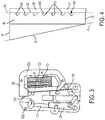
FIG. 1 is a perspective view of an elevator brake with braking wedges in non-braking positions in accordance with embodiments; -
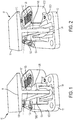
FIG. 2 is a perspective view of an elevator brake with braking wedges in braking positions in accordance with embodiments; -
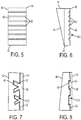
FIG. 3 is a top-down view of the elevator brake ofFIGS. 1 and 2 ; -
FIG. 4 is a schematic illustration of a side of an elevator brake wedge with a low-friction film in accordance with embodiments; -
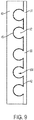
FIG. 5 is a schematic illustration of a major surface of the elevator brake wedge ofFIG. 4 in accordance with embodiments; -
FIG. 6 is a schematic illustration of a side of the elevator brake wedge ofFIG. 4 in accordance with embodiments; -
FIG. 7 is a schematic illustration of a side of an elevator brake wedge with a low-friction film in accordance with further embodiments; -
FIG. 8 is a schematic illustration of a side of an elevator brake wedge with a low-friction film in accordance with further embodiments; and -
FIG. 9 is a schematic illustration of a side of an elevator brake wedge with a low-friction film in accordance with further embodiments. - As will be described below, an elevator brake and an elevator brake wedge are provided and do not rely on adhesion to keep low friction materials in place. Instead, the elevator brake and the elevator brake wedge make use of inherent compression forces generated from safety gear engagement to isolate the low friction surfaces. This is achieved by forming grooves in the backsides of elevator brake safety wedges and by pressing or injecting low friction material into the grooves to form pads or films that can be replaced as needed. When the elevator brake safety wedges are engaged, the compression forces press the low friction film into the grooves and thus keep the low friction film stationary while allowing the elevator brake safety wedges to move into place as required for safety engagement and disengagement.
- With reference to
FIGS. 1-3 , anelevator brake 10 is provided. The elevator brake includes aguide rail 11 and abrake element 12. Theguide rail 11 has across beam 110 and amain beam 111 extending normally from a central portion of thecross beam 110. Thebrake element 12 is configured to be capable of self-engagement and disengagement with respect to opposite sides of themain beam 111 of theguide rail 11. Thebrake element 12 thus includes asupport structure body 120, which is formed to define a track along which themain beam 111 can travel, anactuator 121, first and secondsliding guides safety brake wedges - As shown in
FIGS. 1-3 , thesupport structure body 120 includes abase part 1201 andsidewalls 1202 extending from opposite sides of thebase part 1201. Thebase part 1201 is generally tapered along a longitudinal axis thereof such that thesidewalls 1202 correspondingly taper toward each other. The first and secondsliding guides sidewalls 1202 on either side of theguide rail 11, respectively, and are thus tapered toward each other at a same angle as thesidewalls 1202. The first and secondsliding guides safety brake wedges actuator 121 and configured to assume respective non-braking and braking positions in thesupport structure body 120 between the sides of theguide rail 11 and the first and secondsliding guides - The respective non-braking positions of the first and second
safety brake wedges safety brake wedges support structure body 120 whereas the respective braking positions of the first and secondsafety brake wedges safety brake wedges guides safety brake wedges safety brake wedges guide rail 11. Such inwardly directed force can generate sufficient friction between the first and secondsafety brake wedges guide rail 11 to serve as a brake for an elevator. - In operation, the
actuator 121 moves the first and secondsafety brake wedges safety brake wedges guide rail 11 and the first and second slidingguides safety brake wedges guide rail 11 and the first and second slidingguides - With reference to
FIGS 4-6 , each of the first and secondsafety brake wedges elongate body 40. Theelongate body 40 has a firstmajor surface 41, a secondmajor surface 42 that is generally opposed to the firstmajor surface 41, a firstminor surface 43 and a secondminor surface 44 that is generally opposed to the firstminor surface 43. The secondminor surface 44 has a greater length than the firstminor surface 43 and each of the first and secondmajor surfaces minor surfaces major surfaces minor surface 43. The firstmajor surface 41 is substantially planarized and flat for smooth engagement with the corresponding side of theguide rail 11. The secondmajor surface 42 is formed to define low-frictionfilm securing grooves 45. The low-frictionfilm securing grooves 45 extend from a plane P2 of the secondmajor surface 42 into theelongate body 40 and toward a plane P1 of the firstmajor surface 41. - In operative conditions, each of the first and second
safety brake wedges friction film 50. The low-friction film 50 is formed to include afilm portion 51 and handles 52 protruding from thefilm portion 51. Thehandles 52 are receivable in the low-frictionfilm securing grooves 45 such that the low-friction film 50 is supportively disposed at the secondmajor surface 42 for engagement with a corresponding one of the first and second slidingguides - In accordance with embodiments, the
elongate body 40 includes or is formed of metallic materials or metallic alloys. The low-friction film 50 includes or is formed of at least one of thermoplastic and optionally any one or more of filled or unfilled thermoplastic materials, filled or unfilled polymers, filled or unfilled thermoplastics and/or thermoset or epoxy materials with low friction additives. The polymers may include, but are not limited to, fluoropolymers such as polyvinyl ethylene, polyvinylidene fluoride, ethylene tetrafluoroethylene polymers, polyethylene chlorotrifluoroethylene, etc. The fillers may include, but are not limited to, glass, carbon, graphite or other similar materials. In any case, the material(s) of the low-friction film 50 can be inherently difficult to bond to the material(s) of theelongate body 40. Thus, the low-frictionfilm securing grooves 45 are provided to receive thehandles 52 such that the low-friction film 50 can be held in place. That is, in accordance with further embodiments, material(s) of the secondmajor surface 42 directly and substantially non-adhesively contact material(s) of the low-friction film 50. - As shown in
FIGS. 4-6 , each of the low-frictionfilm securing grooves 45 may have an elongatecross-sectional shape 501 that traverses an entire depth-wise thickness of theelongate body 40. In such cases, a longitudinal axis of each of the low-frictionfilm securing grooves 45 is acutely angled relative to the plane P2 of the secondmajor surface 42 and acorner 450 of each of the low-frictionfilm securing grooves 45 can be rounded so as to avoid chipping or potential damages to the low-friction film 50. In accordance with further alternative embodiments and, with reference toFIGS. 7, 8 and9 , each of the low-frictionfilm securing grooves 45 may have a V-shape 502 in cross-section (seeFIG. 7 ), a tongue-in-flap shape 503 in cross-section (seeFIG. 8 ) or a ball-in-shoulder shape 505 in cross-section (seeFIG. 9 ). - In any case, the shape and orientation of the low-friction
film securing grooves 45 will drive thehandles 52 to assume complementary shapes with complementary orientations and will lead to an increase in compression forces being applied to thehandles 52 as the first andsecond safety wedges friction films 50 being secured in place at the secondmajor surfaces 42 with increasing security and reliability until the respective braking positions are attained and without introducing durability issues typically associated with adhesion bonding. - In accordance with further aspects, a method of forming a safety brake wedge for an elevator is provided. The method includes forming the above-described
elongate body 40 to have the first and second generally opposedmajor surfaces minor surfaces minor surface 44 has a greater length than the firstminor surface 43, such that each of the first and secondmajor surfaces minor surfaces major surface 42 defines the above-described low-frictionfilm securing grooves 45. In accordance with embodiments, theelongate body 40 may be formed by at least one of casting and printing processes, for example. The forming of the low-frictionfilm securing grooves 45 can be conducted as part of the casting or printing of theelongate body 40 as a whole or by machining once theelongate body 40 is already formed. The above-described low-friction film 50 can be formed, for example, by injection molding, compression molding, hot melting or net-shaping of low-friction film material at the secondmajor surface 42 so that the low-friction film material charges into the low-frictionfilm securing grooves 45 to form thehandles 52 while the remainder connects thehandles 52 with each other as thefilm portion 51. - With the configuration and processes described above, minimal if any adhesion is required to secure the low-
friction film 50 to the secondmajor surface 42 as the low-friction film 50 will be under compressive forces and be supported by mechanical interlocking features during engagement. That is, pressures applied by the first and second slidingguides friction film 50 into the low-frictionfilm securing grooves 45 and will thus minimize slipping due to shear. - While the disclosure is provided in detail in connection with only a limited number of embodiments, it should be readily understood that the disclosure is not limited to such disclosed embodiments. Rather, the disclosure can be modified to incorporate any number of variations, alterations, substitutions or equivalent arrangements not heretofore described, but which are commensurate with the spirit and scope of the disclosure. Additionally, while various embodiments of the disclosure have been described, it is to be understood that the exemplary embodiment(s) may include only some of the described exemplary aspects. Accordingly, the disclosure is not to be seen as limited by the foregoing description, but is only limited by the scope of the appended claims.
Claims (15)
- An elevator brake wedge, comprising:an elongate body having first and second generally opposed major surfaces and first and second generally opposed minor surfaces,the second minor surface having a greater length than the first minor surface,each of the first and second major surfaces extending between corresponding first and second ends of the first and second minor surfaces, respectively, andthe second major surface defining low-friction film securing grooves extending from a plane of the second major surface into the elongate body.
- The elevator brake wedge according to claim 1, wherein:the elongate body comprises metallic materials or metallic alloys, andthe low-friction film securing grooves are receptive of low-friction film handles.
- The elevator brake wedge according to claim 1 or 2, wherein a material of the second major surface directly and substantially non-adhesively contacts a material of a low-friction film.
- The elevator brake wedge according to any preceding claim, wherein each of the low-friction film securing grooves has an elongate shape, and optionally
wherein a longitudinal axis of each of the low-friction film securing grooves is acutely angled relative to the plane of the second major surface and a corner of each of the low-friction film securing grooves is rounded. - The elevator brake wedge according to any preceding claim, wherein each of the low-friction film securing grooves has a V-shape, or
a tongue-in-flap shape, or
a ball-in-shoulder shape, - An elevator brake, comprising:first and second sliding guides supportable in a body on either side of a rail;first and second brake wedges configured to assume respective non-braking and braking positions in the body between the sides of the rail and the first and second sliding guides, respectively,each of the first and second brake wedges comprising:a first major surface for engagement with the rail;a second major surface generally opposite the first major surface and formed to define grooves; anda low-friction film having handles which are receivable in the grooves to support the low-friction film at the second major surface for engagement with a corresponding one of the first and second sliding guides.
- The elevator brake according to claim 6, wherein:each of the first and second brake wedges further comprises a first minor surface and a second minor surface generally opposed to and having a greater length than the first minor surface, andthe grooves extend from a plane of the second major surface toward a plane of the first major surface.
- The elevator brake according to claim 6 or 7, wherein:the first and second brake wedges comprise metallic materials or metallic alloys, andthe low-friction film comprises at least one of filled or unfilled thermoplastic materials, filled or unfilled polymers, filled or unfilled thermoplastics and/or thermoset or epoxy materials with low friction additives.
- The elevator brake according to any of claims 6-8, wherein a material of the second major surface directly and substantially non-adhesively contacts a material of the low-friction film.
- The elevator brake according to any of claims 6-9, wherein:each of the grooves has an elongate shape, anda longitudinal axis of each of the grooves is acutely angled relative to the plane of the second major surface and a corner of each of the grooves is rounded.
- The elevator brake according to any of claims 6-10, wherein each of the grooves has a V-shape, or
a tongue-in-flap shape, or
a ball-in-shoulder shape. - A method of forming an elevator brake wedge, the method comprising:forming an elongate body having first and second generally opposed major surfaces and first and second generally opposed minor surfaces such that:the second minor surface has a greater length than the first minor surface;each of the first and second major surfaces extends between corresponding first and second ends of the first and second minor surfaces, respectively; andthe second major surface defines low-friction film securing grooves extending from a plane of the second major surface into the elongate body.
- The method according to claim 12, wherein the forming comprises a forming of the elongate body by at least one of casting and printing.
- The method according to claim 12 or 13, wherein the forming comprises a forming of the low-friction film securing grooves by machining.
- The method according to any of claims 12-14, further comprising at least one of injection molding, compression molding, hot melting and net-shaping of a low-friction film supportable by the low-friction film securing grooves at the second major surface.
Applications Claiming Priority (1)
| Application Number | Priority Date | Filing Date | Title |
|---|---|---|---|
| US15/415,378 US10214385B2 (en) | 2017-01-25 | 2017-01-25 | Elevator brake wedge |
Publications (2)
| Publication Number | Publication Date |
|---|---|
| EP3354613A1 true EP3354613A1 (en) | 2018-08-01 |
| EP3354613B1 EP3354613B1 (en) | 2026-03-11 |
Family
ID=61024640
Family Applications (1)
| Application Number | Title | Priority Date | Filing Date |
|---|---|---|---|
| EP18153153.4A Active EP3354613B1 (en) | 2017-01-25 | 2018-01-24 | Elevator brake wedge having low friction film securing grooves |
Country Status (4)
| Country | Link |
|---|---|
| US (1) | US10214385B2 (en) |
| EP (1) | EP3354613B1 (en) |
| JP (1) | JP7093186B2 (en) |
| CN (1) | CN108341317B (en) |
Families Citing this family (6)
| Publication number | Priority date | Publication date | Assignee | Title |
|---|---|---|---|---|
| CN108147254B (en) * | 2016-12-02 | 2020-12-01 | 奥的斯电梯公司 | Elevator system suspension member termination with improved pressure distribution |
| US11111105B2 (en) * | 2017-01-26 | 2021-09-07 | Otis Elevator Company | Compliant shear layer for elevator termination |
| EP3725725B1 (en) * | 2019-04-17 | 2022-02-09 | KONE Corporation | Rope gripping member of a hoisting apparatus, rope gripping device, terminal arrangement and hoisting apparatus |
| CN113526311B (en) * | 2021-06-28 | 2023-02-03 | 嘉世达电梯有限公司 | Large-tonnage traction machine with self-locking protection function for elevator |
| EP4186842A1 (en) * | 2021-11-25 | 2023-05-31 | Otis Elevator Company | Progressive elevator safety brake |
| CN115076270B (en) * | 2022-07-19 | 2022-11-04 | 杭州安耐特实业有限公司 | Efficient low-energy-consumption brake pad production process |
Citations (4)
| Publication number | Priority date | Publication date | Assignee | Title |
|---|---|---|---|---|
| JPS54173472U (en) * | 1978-05-26 | 1979-12-07 | ||
| US5782319A (en) * | 1996-02-12 | 1998-07-21 | Montgomery Kone Inc. | Elevator car and counterweight safety |
| JPH11217167A (en) * | 1997-11-06 | 1999-08-10 | Otis Elevator Co | Safety brake of elevator |
| KR20110130776A (en) * | 2010-05-28 | 2011-12-06 | 오티스 엘리베이터 컴파니 | Emergency stop of elevator |
Family Cites Families (27)
| Publication number | Priority date | Publication date | Assignee | Title |
|---|---|---|---|---|
| US2326046A (en) | 1942-05-02 | 1943-08-03 | Westinghouse Elec Elevator Co | Elevator safety apparatus |
| US3762512A (en) | 1971-10-29 | 1973-10-02 | Us Elevator Corp | Elevator rail grab safety apparatus |
| JPS54139460U (en) * | 1978-03-22 | 1979-09-27 | ||
| FI85129C (en) | 1989-12-14 | 1992-03-10 | Kone Oy | catching device |
| JP2803974B2 (en) * | 1993-07-30 | 1998-09-24 | 三菱電機株式会社 | Elevator emergency stop device |
| JP3294143B2 (en) * | 1996-09-10 | 2002-06-24 | 株式会社東芝 | Brake shoe for elevator emergency stop device, elevator emergency stop device, and elevator having emergency stop function |
| US6371261B1 (en) * | 1997-11-06 | 2002-04-16 | Otis Elevator Company | Molybdenum alloy elevator safety brakes |
| JPH11199159A (en) | 1997-11-06 | 1999-07-27 | Otis Elevator Co | Elevator safety brake |
| US5979615A (en) * | 1997-11-06 | 1999-11-09 | Otis Elevator Company | Carbon--carbon composite elevator safety brakes |
| US5964322A (en) * | 1997-11-06 | 1999-10-12 | Otis Elevator Company | Elevator safety brake having a plasma sprayed friction coating |
| JP2000179616A (en) * | 1998-12-11 | 2000-06-27 | Daido Metal Co Ltd | Sliding member |
| KR100279363B1 (en) | 1998-12-12 | 2001-01-15 | 장병우 | Emergency stop of elevator |
| DE10083270D2 (en) * | 1999-10-28 | 2002-01-31 | Gustav Meyer Stanztechnik Gmbh | Backing plate |
| JP2002128431A (en) * | 2000-10-20 | 2002-05-09 | Toshiba Corp | Elevator car |
| TW513374B (en) * | 2000-12-08 | 2002-12-11 | Inventio Ag | Safety brake with retardation-dependent braking force |
| JP2004211888A (en) * | 2002-12-24 | 2004-07-29 | Inventio Ag | Brake-shoe for braking cable |
| JP2005234088A (en) * | 2004-02-18 | 2005-09-02 | Sony Corp | Light diffusion film, method for producing the same, and screen |
| CN2685301Y (en) | 2004-03-17 | 2005-03-16 | 上海精润金属制品有限公司 | Elevator safety tongs |
| CN100556785C (en) | 2004-05-21 | 2009-11-04 | 上海乐天电梯部件有限公司 | Elevator main cable brake |
| JP5427682B2 (en) * | 2010-04-16 | 2014-02-26 | 株式会社日立製作所 | Emergency stop device and elevator using the same |
| CN103492302B (en) | 2011-04-19 | 2018-02-13 | 奥的斯电梯公司 | Elevator brake with brake release feature |
| CN104271485A (en) * | 2012-04-30 | 2015-01-07 | 奥的斯电梯公司 | Customized friction for brakes |
| WO2014035382A1 (en) * | 2012-08-29 | 2014-03-06 | Otis Elevator Company | Friction brake assembly with an abradable metal foam brake pad |
| JP2015034081A (en) * | 2013-08-09 | 2015-02-19 | 株式会社日立製作所 | Emergency stop device and elevator device |
| ES2707982T3 (en) | 2014-12-19 | 2019-04-08 | Otis Elevator Co | Belt termination for lift |
| DE202015102837U1 (en) * | 2015-06-01 | 2016-09-06 | Wittur Holding Gmbh | Elevator brake and / or safety gear with welded brake pad |
| CN106351988B (en) * | 2016-11-03 | 2018-08-21 | 石家庄五龙制动器股份有限公司 | The special friction plate of rope brake |
-
2017
- 2017-01-25 US US15/415,378 patent/US10214385B2/en active Active
-
2018
- 2018-01-24 CN CN201810068833.XA patent/CN108341317B/en active Active
- 2018-01-24 JP JP2018009274A patent/JP7093186B2/en not_active Expired - Fee Related
- 2018-01-24 EP EP18153153.4A patent/EP3354613B1/en active Active
Patent Citations (4)
| Publication number | Priority date | Publication date | Assignee | Title |
|---|---|---|---|---|
| JPS54173472U (en) * | 1978-05-26 | 1979-12-07 | ||
| US5782319A (en) * | 1996-02-12 | 1998-07-21 | Montgomery Kone Inc. | Elevator car and counterweight safety |
| JPH11217167A (en) * | 1997-11-06 | 1999-08-10 | Otis Elevator Co | Safety brake of elevator |
| KR20110130776A (en) * | 2010-05-28 | 2011-12-06 | 오티스 엘리베이터 컴파니 | Emergency stop of elevator |
Also Published As
| Publication number | Publication date |
|---|---|
| US10214385B2 (en) | 2019-02-26 |
| JP2018118857A (en) | 2018-08-02 |
| CN108341317A (en) | 2018-07-31 |
| JP7093186B2 (en) | 2022-06-29 |
| EP3354613B1 (en) | 2026-03-11 |
| CN108341317B (en) | 2021-06-08 |
| US20180208434A1 (en) | 2018-07-26 |
Similar Documents
| Publication | Publication Date | Title |
|---|---|---|
| EP3354613B1 (en) | Elevator brake wedge having low friction film securing grooves | |
| CN101195456B (en) | Braking device and guide rail for an elevator with wedge-shaped braking surface | |
| JPH0741272A (en) | Elevator emergency stop device | |
| CN104718149A (en) | Low friction sliding guide shoe for elevator | |
| CN102219140A (en) | Emergency brake device and elevator using the emergency brake device | |
| JP2015009981A (en) | Elevator | |
| US11498803B2 (en) | Elevator car parking brake | |
| CN109476452B (en) | Emergency stop device for elevator | |
| CN101734531A (en) | Brake apparatus for elevator | |
| GB2543291A (en) | Clamping device | |
| CN1982191B (en) | Elevator and emergency braking device for the elevator | |
| KR101117340B1 (en) | Safety device for an elevator | |
| US11912537B2 (en) | Progressive elevator safety brake | |
| CN112977522B (en) | Anti-derailment running mechanism | |
| CN114531870B (en) | Braking device | |
| JP6659005B1 (en) | Elevator safety gear | |
| JP6961558B2 (en) | Electric chain block and spring guide used for it | |
| CN110566581B (en) | Longitudinal grooves on the bonding surface to ensure a local minimum thickness of the bonding layer | |
| US12280413B2 (en) | Hot press forming apparatus and a method for hot press forming a blank | |
| CN108137274B (en) | Assembly of an elevator system, elevator system and method of braking an elevator car | |
| US12280415B2 (en) | Cold working apparatus and a method for cold working a blank | |
| KR102258685B1 (en) | Rotation prevention apparatus for moving nut of electro-mechanical brake | |
| US12162727B2 (en) | Rail stabilizing safety brake | |
| KR102704571B1 (en) | Stacking device for preventing coil from slipping | |
| CN109693986B (en) | Method for preventing elevator from accidental braking |
Legal Events
| Date | Code | Title | Description |
|---|---|---|---|
| PUAI | Public reference made under article 153(3) epc to a published international application that has entered the european phase |
Free format text: ORIGINAL CODE: 0009012 |
|
| STAA | Information on the status of an ep patent application or granted ep patent |
Free format text: STATUS: THE APPLICATION HAS BEEN PUBLISHED |
|
| AK | Designated contracting states |
Kind code of ref document: A1 Designated state(s): AL AT BE BG CH CY CZ DE DK EE ES FI FR GB GR HR HU IE IS IT LI LT LU LV MC MK MT NL NO PL PT RO RS SE SI SK SM TR |
|
| AX | Request for extension of the european patent |
Extension state: BA ME |
|
| STAA | Information on the status of an ep patent application or granted ep patent |
Free format text: STATUS: REQUEST FOR EXAMINATION WAS MADE |
|
| 17P | Request for examination filed |
Effective date: 20190129 |
|
| RBV | Designated contracting states (corrected) |
Designated state(s): AL AT BE BG CH CY CZ DE DK EE ES FI FR GB GR HR HU IE IS IT LI LT LU LV MC MK MT NL NO PL PT RO RS SE SI SK SM TR |
|
| STAA | Information on the status of an ep patent application or granted ep patent |
Free format text: STATUS: EXAMINATION IS IN PROGRESS |
|
| RIC1 | Information provided on ipc code assigned before grant |
Ipc: B22D 25/02 20060101AFI20190423BHEP |
|
| 17Q | First examination report despatched |
Effective date: 20190507 |
|
| RIC1 | Information provided on ipc code assigned before grant |
Ipc: B66B 5/22 20060101AFI20191120BHEP Ipc: B22D 25/02 20060101ALI20191120BHEP |
|
| GRAP | Despatch of communication of intention to grant a patent |
Free format text: ORIGINAL CODE: EPIDOSNIGR1 |
|
| STAA | Information on the status of an ep patent application or granted ep patent |
Free format text: STATUS: GRANT OF PATENT IS INTENDED |
|
| INTG | Intention to grant announced |
Effective date: 20251201 |
|
| GRAS | Grant fee paid |
Free format text: ORIGINAL CODE: EPIDOSNIGR3 |
|
| GRAA | (expected) grant |
Free format text: ORIGINAL CODE: 0009210 |
|
| STAA | Information on the status of an ep patent application or granted ep patent |
Free format text: STATUS: THE PATENT HAS BEEN GRANTED |
|
| AK | Designated contracting states |
Kind code of ref document: B1 Designated state(s): AL AT BE BG CH CY CZ DE DK EE ES FI FR GB GR HR HU IE IS IT LI LT LU LV MC MK MT NL NO PL PT RO RS SE SI SK SM TR |
|
| REG | Reference to a national code |
Ref country code: CH Ref legal event code: F10 Free format text: ST27 STATUS EVENT CODE: U-0-0-F10-F00 (AS PROVIDED BY THE NATIONAL OFFICE) Effective date: 20260311 Ref country code: GB Ref legal event code: FG4D |
|
| REG | Reference to a national code |
Ref country code: DE Ref legal event code: R096 Ref document number: 602018089674 Country of ref document: DE |
|
| REG | Reference to a national code |
Ref country code: IE Ref legal event code: FG4D |