EP3354566B1 - Unité de propulsion avec deux rotors et un carénage - Google Patents
Unité de propulsion avec deux rotors et un carénage Download PDFInfo
- Publication number
- EP3354566B1 EP3354566B1 EP17400002.6A EP17400002A EP3354566B1 EP 3354566 B1 EP3354566 B1 EP 3354566B1 EP 17400002 A EP17400002 A EP 17400002A EP 3354566 B1 EP3354566 B1 EP 3354566B1
- Authority
- EP
- European Patent Office
- Prior art keywords
- rotor
- shrouding
- thrust producing
- producing unit
- assemblies
- Prior art date
- Legal status (The legal status is an assumption and is not a legal conclusion. Google has not performed a legal analysis and makes no representation as to the accuracy of the status listed.)
- Active
Links
- 230000000712 assembly Effects 0.000 title claims description 142
- 238000000429 assembly Methods 0.000 title claims description 142
- 239000013598 vector Substances 0.000 description 11
- 230000033228 biological regulation Effects 0.000 description 5
- 238000006073 displacement reaction Methods 0.000 description 3
- 230000006378 damage Effects 0.000 description 2
- 239000002184 metal Substances 0.000 description 2
- 208000027418 Wounds and injury Diseases 0.000 description 1
- 230000001133 acceleration Effects 0.000 description 1
- 230000004308 accommodation Effects 0.000 description 1
- 230000009286 beneficial effect Effects 0.000 description 1
- 150000001875 compounds Chemical class 0.000 description 1
- 230000007423 decrease Effects 0.000 description 1
- 230000000694 effects Effects 0.000 description 1
- 238000004146 energy storage Methods 0.000 description 1
- 238000005516 engineering process Methods 0.000 description 1
- 230000007613 environmental effect Effects 0.000 description 1
- 208000014674 injury Diseases 0.000 description 1
- 238000012986 modification Methods 0.000 description 1
- 230000004048 modification Effects 0.000 description 1
- 238000005204 segregation Methods 0.000 description 1
- 230000035945 sensitivity Effects 0.000 description 1
- 238000000926 separation method Methods 0.000 description 1
- 230000000087 stabilizing effect Effects 0.000 description 1
Images


Classifications
-
- B—PERFORMING OPERATIONS; TRANSPORTING
- B64—AIRCRAFT; AVIATION; COSMONAUTICS
- B64C—AEROPLANES; HELICOPTERS
- B64C11/00—Propellers, e.g. of ducted type; Features common to propellers and rotors for rotorcraft
- B64C11/001—Shrouded propellers
-
- B—PERFORMING OPERATIONS; TRANSPORTING
- B64—AIRCRAFT; AVIATION; COSMONAUTICS
- B64C—AEROPLANES; HELICOPTERS
- B64C11/00—Propellers, e.g. of ducted type; Features common to propellers and rotors for rotorcraft
- B64C11/46—Arrangements of, or constructional features peculiar to, multiple propellers
- B64C11/48—Units of two or more coaxial propellers
-
- B—PERFORMING OPERATIONS; TRANSPORTING
- B64—AIRCRAFT; AVIATION; COSMONAUTICS
- B64C—AEROPLANES; HELICOPTERS
- B64C27/00—Rotorcraft; Rotors peculiar thereto
- B64C27/04—Helicopters
- B64C27/08—Helicopters with two or more rotors
-
- B—PERFORMING OPERATIONS; TRANSPORTING
- B64—AIRCRAFT; AVIATION; COSMONAUTICS
- B64C—AEROPLANES; HELICOPTERS
- B64C27/00—Rotorcraft; Rotors peculiar thereto
- B64C27/20—Rotorcraft characterised by having shrouded rotors, e.g. flying platforms
-
- B—PERFORMING OPERATIONS; TRANSPORTING
- B64—AIRCRAFT; AVIATION; COSMONAUTICS
- B64D—EQUIPMENT FOR FITTING IN OR TO AIRCRAFT; FLIGHT SUITS; PARACHUTES; ARRANGEMENTS OR MOUNTING OF POWER PLANTS OR PROPULSION TRANSMISSIONS IN AIRCRAFT
- B64D25/00—Emergency apparatus or devices, not otherwise provided for
-
- B—PERFORMING OPERATIONS; TRANSPORTING
- B64—AIRCRAFT; AVIATION; COSMONAUTICS
- B64U—UNMANNED AERIAL VEHICLES [UAV]; EQUIPMENT THEREFOR
- B64U10/00—Type of UAV
- B64U10/10—Rotorcrafts
- B64U10/13—Flying platforms
- B64U10/14—Flying platforms with four distinct rotor axes, e.g. quadcopters
-
- B—PERFORMING OPERATIONS; TRANSPORTING
- B64—AIRCRAFT; AVIATION; COSMONAUTICS
- B64U—UNMANNED AERIAL VEHICLES [UAV]; EQUIPMENT THEREFOR
- B64U30/00—Means for producing lift; Empennages; Arrangements thereof
- B64U30/20—Rotors; Rotor supports
- B64U30/26—Ducted or shrouded rotors
-
- B—PERFORMING OPERATIONS; TRANSPORTING
- B64—AIRCRAFT; AVIATION; COSMONAUTICS
- B64U—UNMANNED AERIAL VEHICLES [UAV]; EQUIPMENT THEREFOR
- B64U50/00—Propulsion; Power supply
- B64U50/10—Propulsion
- B64U50/13—Propulsion using external fans or propellers
- B64U50/14—Propulsion using external fans or propellers ducted or shrouded
-
- B—PERFORMING OPERATIONS; TRANSPORTING
- B64—AIRCRAFT; AVIATION; COSMONAUTICS
- B64U—UNMANNED AERIAL VEHICLES [UAV]; EQUIPMENT THEREFOR
- B64U10/00—Type of UAV
- B64U10/10—Rotorcrafts
- B64U10/13—Flying platforms
Definitions
- the invention is related to a thrust producing unit for producing thrust in a predetermined direction, the thrust producing unit comprising at least two rotor assemblies and a shrouding.
- the invention is further related to a multirotor aircraft with at least one thrust producing unit for producing thrust in a predetermined direction, the thrust producing unit comprising at least two rotor assemblies and a shrouding.
- multirotor aircrafts are also known from the state of the art, such as e. g. the Boeing CH-47 tandem rotor helicopter, the Bell XV-3 tilt rotor aircraft, the Bell XV-22 quad tilt with ducted rotors, as well as so-called drones and, more particularly, so-called quad drones, such as e. g. described in the documents US 2015/0127209 A1 , DE 10 2005 022 706 A1 and KR 101 451 646 B1 .
- multirotor aircraft studies and fictions also exist, such as e. g. the skyflyer SF MK II from Skyflyer Technology GmbH and the multicopter shown in the Avatar movie.
- each thrust producing unit includes one or more rotors or propellers and is, usually, designed for specific flight conditions.
- a thrust producing unit that is designed as an airplane propeller operates at its optimum in cruise conditions
- a thrust producing unit that is designed as propeller of a compound helicopter is rather optimized for hover or forward flight conditions
- a thrust producing unit that implements e. g. a so-called Fenestron® tail rotor is particularly designed for hover conditions.
- the document US2014091172 describes a rotary wing vehicle including a streamlined body suitable for high-speed horizontal flight.
- the streamlined body is adapted to carry human pilots or passengers.
- the rotary wing vehicle includes counter-rotating rotor blades that are rotatable about common axis of a shrouded mast and a streamlined mast shroud located between and apart from the counter-rotating rotor blades.
- the rotary wing vehicle includes a pusher propeller and stabilizing tail fins.
- the shrouded mast has an airfoil cross section as viewed from above to reduce frontal drag.
- the shrouded shroud is secured to the body shell and to body shell standoffs which is also secured the mast shroud surrounding only the mast tube.
- the document WO0064736 describes an UAV which includes a fuselage with a toroid portion having a generally hemi cylindrical aerodynamic profile.
- a rotor assembly is mounted within a duct that extends substantially vertically through the fuselage, via support struts rigidly attached to the fuselage. Thus, the rotor assembly is in a fixed co-axial relation with respect to the duct.
- wings are attached to and extend laterally outward from the sides of the fuselage.
- a propelling shroud is further formed on the aft fuselage around a pusher propeller rotor, so as to protect the rotor from environmental contact.
- Two engines of the UAV aircrafts continue to operate in the event of an engine failure, but an overrunning clutch is incorporated to automatically disengage an inoperative engine.
- the respective thrust producing unit is optimized for operation in axial air flow conditions, i. e. in an air flow direction that is oriented at least approximately along a rotor axis resp. rotation axis of the given one or more rotors or propellers and, therefore, referred to as an axial air flow direction. If, however, the respective thrust producing unit is operated in transversal air flow conditions, i. e. in an air flow direction that is oriented transverse to the rotor axis of the given one or more rotors or propellers and, therefore, referred to as a non-axial air flow direction, a respective efficiency of the thrust producing unit usually decreases considerably.
- the thrust producing units will be subjected to axial air flow conditions e. g. during a vertical take-off phase. Subsequently, respective thrust vectors generated by the thrust producing units can be inclined in a predetermined direction, e. g. by rotating the thrust producing units accordingly, so that the multirotor aircraft gains velocity and leaves a previous hovering condition such that is converts to forward flight, wherein the thrust producing units are subjected to transversal air flow conditions.
- respective ducts or shrouds which are beneficial in axial air flow conditions, are penalizing by generating a comparatively large amount of drag.
- an underlying advantage provided by the ducts or shrouds in hovering turns out to be a disadvantage in forward flight, which increases with increasing a respective advancing speed of the multirotor aircraft in forward flight.
- a ducted rotor or propeller i. e. a rotor or propeller that is provided with a duct or shroud
- an equivalent isolated or non-ducted rotor or propeller i. e. a rotor or propeller without duct or shroud
- the presence of a duct or shroud increases a respectively produced thrust of a given thrust producing unit at constant required power. Therefore, conventional thrust producing units are frequently provided with one or more rotors or propellers that is/are completely enclosed in an associated duct or shroud.
- This classical configuration uses a respective rotor or propeller induced velocity to generate thrust also from the duct or shroud.
- a duct or shroud is defined by an enclosed, annular surface that is arranged around a rotor or propeller in order to improve respective aerodynamics and performance of the rotor or propeller.
- a conventional duct or shroud which is usually not rotatable, i. e. cannot be inclined, and has a height that is selected such that a given rotor or propeller is fully enclosed therein.
- the duct or shroud increases an overall weight of a respective multirotor aircraft due to its size, and further increases drag e. g. during forward flight, i. e. in transversal air flow conditions, as the duct or shroud cannot be inclined for adjustment of an underlying thrust vector direction.
- the comparatively large size also leads to a comparatively large projection surface on which wind and/or wind gust may act. This leads to an increased overpower necessity for the respective multirotor aircraft.
- two or more rotor or propellers are e. g.
- a given duct or shroud that is provided for enclosing these rotors or propellers will even require a still larger height and be still heavier.
- conventional ducts or shrouds are usually not actively rotated and must be designed comparatively stiff, as usually a minimum gap between rotors or propellers and duct or shroud surface is requested.
- conventional ducts or shrouds of respective thrust producing units are not suitable for enclosing differently configured rotors or propellers, i. e. rotors or propellers having differing inclinations, positioning and/or sizes resp. diameters.
- a thrust vector that is produced in operation in axial air flow conditions is aligned with a rotor axis of a respective rotor or propeller of the thrust producing unit and directed against a direction of a velocity field induced by the rotor or propeller in operation.
- the rotor or propeller accelerates a certain mass-flow through an associated rotor or propeller plane or disk.
- a resulting flow acceleration which occurs when air traverses the rotor or propeller plane or disk, forms areas of under-pressure around a respective collector region of the duct or shroud, thus, generating additional thrust.
- This generation of additional thrust is an important advantage resulting from the use of the duct or shroud that is, however, strongly penalizing in forward flight, i. e. in transversal air flow conditions, due to additional drag generated by the duct or shroud.
- the additional drag is directly proportional to a respective frontal area that is defined by a product of height and width of the duct or shroud.
- an object of the present invention to provide a new thrust producing unit, in particular for use with multirotor aircrafts, which exhibits improved aerodynamics and performances.
- a thrust producing unit for producing thrust in a predetermined direction comprising the features of claim 1.
- a thrust producing unit for producing thrust in a predetermined direction comprises at least two rotor assemblies and a shrouding.
- Each one of the at least two rotor assemblies defines an associated rotor plane.
- a first rotor assembly of the at least two rotor assemblies is provided for operating in a failure-free operating mode of the thrust producing unit and a second rotor assembly of the at least two rotor assemblies is provided for operating at least in case of a failure of the first rotor assembly.
- the shrouding accommodates at most one of the at least two rotor assemblies.
- the inventive thrust producing unit is implemented as a shrouded multiple rotor assembly configuration that leads to a significantly reduced drag in transversal air flow conditions, e. g. in forward flight of a given multirotor aircraft that uses the inventive thrust producing unit, and furthermore exhibits a significantly lower weight than a conventional shrouded thrust producing unit having a single shrouding that completely encloses two rotor or propeller assemblies, while having comparable performances in axial air flow conditions, i. e. in hover flight of the respective multirotor aircraft.
- a conventional shrouded thrust producing unit having a single shrouding that completely encloses two or more, preferentially counter-rotating rotor or propeller assemblies provides the same thrust versus power characteristics than e. g. a thrust producing unit having a shorter shrouding that encloses only one of the two or more rotor or propeller assemblies, such as the inventive thrust producing unit, while leaving the other(s) unshrouded, i. e. exposed to the air.
- a respective velocity field induced by the at least two rotor or propeller assemblies with the long and short shroudings is such that the under-pressure field generated on the respective shroud collector is also the same for the long and short shroud configurations.
- This likewise applies to a configuration featuring multiple rotor or propeller assemblies, each being enclosed in a single associated shrouding having a minimized height.
- the shrouding of the inventive thrust producing unit is used as an additional lifting device during hover and forward flight cases of a multirotor aircraft that features the inventive thrust producing unit and, thus, beneficially allows reduction of a respective power consumption of the at most one of the at least two rotor assemblies that is accommodated in the shrouding.
- the shrouding advantageously allows to reduce at least an underlying diameter of the at most one of the at least two rotor assemblies that is accommodated therein, since the shrouding increases its effectiveness.
- the shrouding beneficially provides for a shielding effect with respect to the at most one of the at least two rotor assemblies that is accommodated therein and, thus, advantageously allows to reduce a respective rotor noise footprint on ground.
- the inventive thrust producing unit can be provided with a foreign object protection, e. g. by being enclosed by a grid, in order to protect the at least rotor assemblies from foreign objects.
- a foreign object protection beneficially prevents misuse and accidents by and of individuals, e. g. by preventing them from getting their hands caught in rotating parts, thereby leading to an increased operational safety level of the inventive thrust producing unit.
- the rotor assemblies can be positioned above each other and rotated in a counter rotating manner, leading to a thrust producing unit that provides for an increased safety level and that allows reduction of the overall dimensions of an associated multirotor aircraft, resulting in a comparatively small aircraft, since the two or more rotor planes can be combined in a single thrust producing unit.
- the at least two rotor assemblies of the inventive thrust producing unit each of which defines an associated rotor plane or surface, are positioned on top of each other, either coaxially or with separate individual rotor axes, and can be inclined with respect to each other.
- inventive thrust producing unit is adapted for providing torque individually as a result of its counter-rotating rotor assemblies, which can be used to maneuver a given multirotor aircraft that features the inventive thrust producing unit, e. g. with respect to yawing.
- a predetermined distance between the associated rotor planes of the first and second rotor assemblies is comprised in a range between 0.01*D and 2*D, and preferably amounts to 0.17*D, wherein D defines a diameter of the second rotor assembly.
- the shrouding accommodates the second rotor assembly of the at least two rotor assemblies.
- the shrouding is arranged in-between the first rotor assembly and the second rotor assembly of the at least two rotor assemblies without accommodating one of the first and second rotor assemblies.
- the shrouding exhibits an outer diameter that is smaller than a diameter of at least one of the at least two rotor assemblies.
- the shrouding accommodates the second rotor assembly of the at least two rotor assemblies, wherein an additional shrouding is provided that accommodates the first rotor assembly.
- a predetermined distance between the associated rotor planes of the first and second rotor assemblies is comprised in a range between 0.01*D and 2*D, and preferably amounts to 0.17*D, wherein D defines a diameter of the second rotor assembly.
- the shrouding and the additional shrouding exhibit each a height that is comprised in a range between 0.04*D and 1*D, wherein D defines a diameter of the second rotor assembly.
- the shrouding and the additional shrouding are spaced apart from each other by an offset that is comprised in a range between 0.01*D and 2*D, and preferably amounts to 0.17*D, wherein D defines a diameter of the second rotor assembly.
- the additional shrouding comprises a leading edge that points away from the shrouding, wherein a distance between the leading edge and the associated rotor plane of the first rotor assembly is comprised in a range between -1*D and 1*D, and preferably amounts to -0.08*D, wherein D defines a diameter of the second rotor assembly, and wherein the first rotor assembly is arranged outside of the additional shrouding if the distance is comprised in the range between -1*D and 0, preferably above the leading edge.
- the first rotor assembly comprises at least two rotor blades and the second rotor assembly comprises at least two rotor blades.
- the first one of the at least two rotor assemblies defines a first rotor axis and the second one of the at least two rotor assemblies defines a second rotor axis, the first and second rotor axes being spaced apart from each other.
- the first one of the at least two rotor assemblies defines a first rotor axis and the second one of the at least two rotor assemblies defines a second rotor axis, the first and second rotor axes being coaxially arranged.
- the first and second rotor axes are inclined by associated inclination angles comprised in a range between -60° and +60°, wherein the associated inclination angles preferably amount to 0°.
- the first rotor assembly is adapted to be rotated in a first rotation direction in operation and the second rotor assembly is adapted to be rotated in a second rotation direction in operation.
- the present invention further relates to a multirotor aircraft comprising at least one thrust producing unit that is configured as described above.
- the shrouding of the inventive thrust producing unit allows reducing respective overall dimensions of the inventive multirotor aircraft that features the inventive thrust producing unit. Furthermore, individuals approaching the shrouded thrust producing unit are protected against injury, foreign object damages of the thrust producing unit in operation, such as e. g. bird strike or wire strike, can securely and reliably be prevented, and the overall operational safety of the associated multirotor aircraft in the case of air collisions can be improved.
- respective aerodynamics, acoustics and performance can be improved by reducing a respective rotor blade loading in operation, reducing an overall power consumption, reducing a respective noise emission and ameliorating functioning in hover and forward flight of the inventive multirotor aircraft.
- an underlying required diameter of the thrust producing unit can be reduced.
- lift of the inventive multirotor aircraft is improved by the shrouding itself, potentially reducing the overall power required by the inventive multirotor aircraft.
- inventive aircraft is described above with reference to a multirotor structure with multiple rotor assemblies, it could likewise be implemented as a multipropeller structure with multiple propeller assemblies or as a multipropeller and -rotor structure. More specifically, while rotors are generally fully articulated, propellers are generally not articulated at all. However, both can be used for generating thrust and, thus, for implementing the thrust producing units according to the present invention. Consequently, any reference to rotors or rotor structures in the present description should likewise be understood as a reference to propellers and propeller structures, so that the inventive multirotor aircraft can likewise be implemented as a multipropeller and/or multipropeller and -rotor aircraft.
- the present invention principally relates to a multiple thrust configuration with rotors/propellers that define rotor/propeller planes, which can be selected to be positioned atop of each other individually, a rotor shrouding for enclosing any rotating parts of at most one of the rotors/propellers, at least one electrical engine which drives each rotor/propeller, wherein each engine can be segregated in order to increase a provided safety level, and wherein a logic connection preferably exists between battery and electrical engines, the logic connection preferentially comprising a redundant design increasing the safety level in case of failure, and wherein preferably a battery redundancy layout with an appropriate safety level in case of failure is provided.
- the inventive multirotor aircraft is designed for transportation of passengers and is, in particular, suitable and adapted for being certificated for operation within urban areas. It is preferably easy to fly, has multiple redundancies, meets the safety demands of the authorities, is cost efficient in design and only creates comparatively low noise.
- the inventive multirotor aircraft has a comparatively small rotor diameter with a light weight design and a fixed angle of incident, and is nevertheless adapted for fulfilment of an emergency landing, although these rotor characteristics lead to a comparatively low inertia and a non-adjustable torque in operation.
- the inventive multirotor aircraft is capable of hovering and comprises a distributed propulsion system. It is further preferably designed with autorotation capability, which is necessary amongst other requirements in order to meet authority regulations, such as e.g. FAR and EASA regulations, regarding safety failure modes that amount up to approximately 1*10 -7 failures per flight hour for the entire multirotor aircraft. In the aeronautical sector, these safety levels are typically defined by the so-called Design Assurance Levels (DAL) A to D.
- DAL Design Assurance Levels
- the inventive multirotor aircraft fulfils the authorities' regulation safety level needed to transport passengers. This is preferably achieved by a combination and correlation of:
- Figure 1 shows a multirotor aircraft 1 with an aircraft airframe 2 to which is not claimed by the present invention.
- the aircraft airframe 2 defines a supporting structure that is also referred to hereinafter as the fuselage of the multirotor aircraft 1.
- the fuselage 2 has an extension in longitudinal direction 1a and an extension in lateral direction 1b and preferably defines an internal volume 2a that is at least adapted for transportation of passengers, so that the multirotor aircraft 1 as a whole is adapted for transportation of passengers.
- the internal volume 2a is preferably further adapted for accommodating operational and electrical equipment, such as e. g. an energy storage system that is required for operation of the multirotor aircraft 1.
- the multirotor aircraft 1 comprises a plurality of thrust producing units 3.
- the plurality of thrust producing units 3 comprises at least two and preferentially four thrust producing units 3a, 3b, 3c, 3d.
- the thrust producing units 3a, 3b, 3c, 3d are embodied for producing thrust (9 in Figure 3 ) in operation, such that the multirotor aircraft 1 is able to hover in the air as well as to fly in any forward or rearward direction.
- the thrust producing units 3a, 3b, 3c, 3d are structurally connected to the fuselage 2.
- this is achieved by means of a plurality of structural supports 4.
- the thrust producing unit 3a is preferably connected to the fuselage 2 via a structural support 4a, the thrust producing unit 3b via a structural support 4b, the thrust producing unit 3c via a structural support 4c and the thrust producing unit 3d via a structural support 4d, wherein the structural supports 4a, 4b, 4c, 4d define the plurality of structural supports 4.
- At least one of the thrust producing units 3a, 3b, 3c, 3d comprises an associated shrouding in order to improve underlying aerodynamics and to increase operational safety.
- a plurality of shrouding units 6 is shown with four separate shroudings 6a, 6b, 6c, 6d.
- the shrouding 6a is associated with the thrust producing unit 3a, the shrouding 6b with the thrust producing unit 3b, the shrouding 6c with the thrust producing unit 3c and the shrouding 6d with the thrust producing unit 3d.
- the shroudings 6a, 6b, 6c, 6d can be made of a simple sheet metal. Alternatively, they may have a complex geometry, such as e. g. described below with reference to Figure 5 .
- shroudings 6a, 6b, 6c, 6d can be connected to the fuselage 2 together with the structural supports 4a, 4b, 4c, 4d, in order to reinforce the connection between the thrust producing units 3a, 3b, 3c, 3d and the fuselage 2.
- shroudings 6a, 6b, 6c, 6d can be connected to the fuselage 2.
- each one of the thrust producing units 3a, 3b, 3c, 3d is equipped with at least two rotor assemblies.
- the thrust producing unit 3a is equipped with two rotor assemblies 7a, 8a
- the thrust producing unit 3b is equipped with two rotor assemblies 7b, 8b
- the thrust producing unit 3c is equipped with two rotor assemblies 7c, 8c
- the thrust producing unit 3d is equipped with two rotor assemblies 7d, 8d.
- the rotor assemblies 7a, 7b, 7c, 7d illustratively define a plurality of upper rotor assemblies 7 and the rotor assemblies 8a, 8b, 8c, 8d illustratively define a plurality of lower rotor assemblies 8.
- the plurality of upper and lower rotor assemblies 7, 8 is preferably connected to the plurality of structural supports 4 by means of a plurality of gearbox fairings 5.
- the upper and lower rotor assemblies 7a, 8a are connected to the structural support 4a by means of a gearbox fairing 5a
- the upper and lower rotor assemblies 7b, 8b are connected to the structural support 4b by means of a gearbox fairing 5b
- the upper and lower rotor assemblies 7c, 8c are connected to the structural support 4c by means of a gearbox fairing 5c
- the upper and lower rotor assemblies 7d, 8d are connected to the structural support 4d by means of a gearbox fairing 5d.
- each one of the upper rotor assemblies 7a, 7b, 7c, 7d defines an associated upper rotor plane (21 in Figure 6 ) and each one of the lower rotor assemblies 8a, 8b, 8c, 8d defines an associated lower rotor plane (22 in Figure 6 ).
- the upper and lower rotor assemblies 7a, 7b, 7c, 7d, 8a, 8b, 8c, 8d define pairs of upper and lower rotor assemblies 7a, 8a; 7b, 8b; 7c, 8c; 7d, 8d that are accommodated in the shroudings 6a, 6b, 6c, 6d, respectively, so that the associated upper and lower rotor planes (21, 22 in Figure 6 ) are located inside the shroudings 6a, 6b, 6c, 6d of the multirotor aircraft 1.
- the multirotor aircraft 1 comprises an aircraft operating structure and a redundant security architecture.
- the aircraft operating structure is preferably adapted for operation of the multirotor aircraft 1 in failure-free operating mode and the redundant security architecture is preferably at least adapted for operation of the multirotor aircraft 1 in case of a failure of the aircraft operating structure.
- the redundant security architecture is provided to comply preferentially with applicable authority regulations and certification requirements regarding passenger transportation.
- the aircraft operating structure comprises at least a first part of the upper and lower rotor assemblies 7a, 7b, 7c, 7d, 8a, 8b, 8c, 8d and the redundant security architecture comprises at least a second part of the upper and lower rotor assemblies 7a, 7b, 7c, 7d, 8a, 8b, 8c, 8d.
- a first one of the upper and lower rotor assemblies 7a, 8a, 7b, 8b, 7c, 8c, 7d, 8d of each thrust producing unit 3a, 3b, 3c, 3d is associated with the aircraft operating structure, while a second one is associated with the redundant security architecture.
- the upper rotor assemblies 7a, 7b, 7c, 7d are associated with the aircraft operating structure and the lower rotor assemblies 8a, 8b, 8c, 8d are associated with the redundant security architecture.
- the lower rotor assemblies 8a, 8b, 8c, 8d operate the multirotor aircraft 1 in order to avoid e. g. a crash thereof.
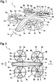
- Figure 2 shows the multirotor aircraft 1 of Figure 1 with the thrust producing units 3a, 3b, 3c, 3d that are connected to the fuselage 2.
- the thrust producing units 3a, 3b, 3c, 3d respectively comprise the upper and lower rotor assemblies 7a, 7b; 7b, 8b; 7c, 8c; 7d, 8d, which are preferably arranged in a side-by-side configuration with congruent rotor axes (12 in Figure 3 and Figure 4 ).
- the upper rotor assemblies 7a, 7b, 7c, 7d are arranged above the lower rotor assemblies 8a, 8b, 8c, 8d such that the upper and lower rotor assemblies 7a, 7b; 7b, 8b; 7c, 8c; 7d, 8d are stacked, i. e. arranged on top of each other with congruent rotor axes (12 in Figure 3 and Figure 4 ).
- alternative configurations are likewise contemplated, such as e. g. described below with reference to Figure 11 .
- the thrust producing units 3a, 3b, 3c, 3d are all exemplarily arranged laterally with respect to the fuselage 2, i. e. on the left or right side of the fuselage 2 seen in its longitudinal direction 1a.
- the left side corresponds to the lower side and the right side to the upper side of the fuselage 2 as shown in Figure 2 .
- the fuselage 2 is exemplarily embodied such that the laterally arranged thrust producing units 3a, 3b, 3c, 3d define at least approximately a trapezoidal shape.
- Figure 3 shows the multirotor aircraft 1 of Figure 1 and Figure 2 in an exemplary failure-free operating mode.
- the plurality of thrust producing units 3 produce airstreams in a thrust producing airstream direction 9 by means of the plurality of upper and/or lower rotor assemblies 7, 8 that is suitable to lift the multirotor aircraft 1 off ground 10.
- Each one of the plurality of upper rotor assemblies 7 defines a first rotor axis and each one of the plurality of lower rotor assemblies 8 defines a second rotor axis.
- the first and second rotor axes are respectively congruent, i. e. coaxially arranged, so that the plurality of upper and lower rotor assemblies 7, 8 define a plurality of coaxially arranged rotor axes 12.
- the upper and lower rotor assemblies 7c, 8c define first and second congruent rotor axes, which are commonly referred to as the rotor axis 12c
- the upper and lower rotor assemblies 7d, 8d define first and second congruent rotor axes, which are commonly referred to as the rotor axis 12d.
- the plurality of thrust producing units 3 is inclined in the longitudinal direction 1a of the multirotor aircraft 1 by a plurality of longitudinal inclination angles 11 in order to increase the manoeuvrability of the multirotor aircraft 1 and to reduce an overall inclination in the longitudinal direction 1a of the multirotor aircraft 1 during forward flight.
- the plurality of longitudinal inclination angles 11 is illustratively defined between a vertical reference line 10a of the multirotor aircraft 1 and the plurality of coaxially arranged rotor axes 12.
- a possible and realized number of the plurality of longitudinal inclination angles 11 depends on an underlying number of provided thrust producing units.
- At least one of the plurality of thrust producing units 3 is inclined in the longitudinal direction 1a of the multirotor aircraft 1 by a first longitudinal inclination angle defined between a vertical reference line 10a of the multirotor aircraft 1 and the first and second congruent rotor axes of this at least one of the plurality of thrust producing units 3.
- the first longitudinal inclination angle is preferably comprised in a range between -45° and +80°, and preferentially amounts to 7°.
- the thrust producing unit 3c of the plurality of thrust producing units 3 is inclined by a first longitudinal inclination angle 11a defined between the vertical reference line 10a and the rotor axis 12c, wherein the first longitudinal inclination angle 11a is preferably comprised in a range between -45° and +80°, and preferentially amounts to 7°.
- the thrust producing unit 3a of the plurality of thrust producing units 3 of Figure 1 and Figure 2 is preferably also inclined by the first longitudinal inclination angle 11a.
- At least one of the plurality of thrust producing units 3 is inclined in the longitudinal direction 1a of the multirotor aircraft 1 by a second longitudinal inclination angle defined between the vertical reference line 10a and the first and second congruent rotor axes of this at least one of the plurality of thrust producing units 3.
- the second longitudinal inclination angle is preferably also comprised in a range between -45° and +80°, and preferentially amounts to 7°.
- the thrust producing unit 3d of the plurality of thrust producing units 3 is inclined by a second longitudinal inclination angle 11b defined between the vertical reference line 10a and the rotor axis 12d, wherein the second longitudinal inclination angle 11b is preferably comprised in a range between -45° and +80°, and preferentially amounts to 7°.
- the thrust producing unit 3b of the plurality of thrust producing units 3 of Figure 1 and Figure 2 is preferably also inclined by the second longitudinal inclination angle 11b.
- Figure 4 shows the multirotor aircraft 1 with the fuselage 2 of Figure 3 , which illustratively comprises a width 2b.
- the latter is defined as a maximum distance measured orthogonally to the longitudinal direction 1a of the multirotor aircraft 1 between the respective outmost left hand and right hand side surfaces of the fuselage 2.
- the multirotor aircraft 1 is shown in the exemplary failure-free operating mode, wherein the plurality of thrust producing units 3 produce airstreams in the thrust producing airstream direction 9 by means of the plurality of upper and lower rotor assemblies 7, 8.
- the upper and lower rotor assemblies 7c, 8c define the rotor axis 12c and the upper and lower rotor assemblies 7d, 8d define the rotor axis 12d.
- the upper and lower rotor assemblies 7a, 8a exemplarily define first and second congruent rotor axes, which are commonly referred to as the rotor axis 12a
- the upper and lower rotor assemblies 7b, 8b define first and second congruent rotor axes, which are commonly referred to as the rotor axis 12b.
- the rotor axes 12a, 12b, 12c, 12d are preferably implemented as described in order to reduce the overall complexity, system weight as well as geometrical size of the multirotor aircraft 1.
- the plurality of thrust producing units 3 is inclined in the lateral direction 1b of the multirotor aircraft 1 by a plurality of lateral inclination angles 13 in order to provide reduced gust sensitivity and to increase the manoeuvrability of the multirotor aircraft 1.
- the plurality of lateral inclination angles 13 is illustratively defined between the vertical reference line 10a of the multirotor aircraft 1 and the plurality of coaxially arranged rotor axes 12.
- a possible and realized number of the plurality of lateral inclination angles 13 depends on an underlying number of provided thrust producing units.
- At least one of the plurality of thrust producing units 3 is inclined in the lateral direction 1b of the multirotor aircraft 1 by a first lateral inclination angle defined between the vertical reference line 10a of the multirotor aircraft 1 and the first and second congruent rotor axes of this at least one of the plurality of thrust producing units 3.
- the first lateral inclination angle is preferably comprised in a range between -45° and +80°, and preferentially amounts to 5°.
- the thrust producing unit 3a of the plurality of thrust producing units 3 is inclined by a first lateral inclination angle 13a defined between the vertical reference line 10a and the rotor axis 12a, wherein the first lateral inclination angle 13a is preferably comprised in a range between -45° and +80°, and preferentially amounts to 5°.
- the thrust producing unit 3c of the plurality of thrust producing units 3 of Figure 1 and Figure 2 is preferably also inclined by the first lateral inclination angle 13a.
- At least one of the plurality of thrust producing units 3 is inclined in the lateral direction 1b of the multirotor aircraft 1 by a second lateral inclination angle defined between the vertical reference line 10a of the multirotor aircraft 1 and the first and second congruent rotor axes of this at least one of the plurality of thrust producing units 3.
- the second lateral inclination angle is preferably comprised in a range between -45° and +80°, and preferentially amounts to 5°.
- the thrust producing unit 3b of the plurality of thrust producing units 3 is inclined by a second lateral inclination angle 13b defined between the vertical reference line 10a and the rotor axis 12b, wherein the second lateral inclination angle 13b is preferably comprised in a range between -45° and +80°, and preferentially amounts to 5°.
- the thrust producing unit 3d of the plurality of thrust producing units 3 of Figure 1 and Figure 2 is preferably also inclined by the second lateral inclination angle 13b.
- Figure 5 shows the thrust producing unit 3d of the preceding figures, with its upper rotor assembly 7d, its lower rotor assembly 8d, its gearbox fairing 5d and its shrouding 6d for further illustrating an exemplary configuration thereof.
- the thrust producing units 3a, 3b, 3c of the preceding figures preferably comprise similar configurations, so that the thrust producing unit 3d is only described representative for all thrust producing units 3a, 3b, 3c, 3d, for brevity and conciseness.
- the shrouding 6d has an inner surface 20a and an outer surface 20b with an outer diameter 20f.
- the shrouding 6d exemplarily further defines a leading edge 20d and a trailing edge 20e.
- an internal volume 20c is defined between the inner surface 20a, the outer surface 20b, the leading edge 20d and the trailing edge 20e.
- This inner volume 20c can e. g. be used as storage volume for a battery system of the multirotor aircraft 1 of the preceding figures.
- the shrouding 6d can be made of a simple pressed, bended metal sheet such that the inner and outer surfaces 20a, 20b are substantially parallel to each other, i. e. feature an almost constant distance with respect to each other. However, it may as well have a complex geometry. Illustratively, the shrouding 6d accommodates the upper rotor assembly 7d and the lower rotor assembly 8d.
- the upper rotor assembly 7d comprises at least two and, illustratively, three rotor blades 18a, 18b, 18c for producing thrust in operation.
- the lower rotor assembly 8d preferably also comprises at least two and, illustratively, three rotor blades 19a, 19b, 19c for producing thrust in operation.
- At least one first engine 14a is provided for driving the rotor blades 18a, 18b, 18c, i. e. the upper rotor assembly 7d in operation and at least one second engine 14b is provided for driving the rotor blades 19a, 19b, 19c, i. e. the lower rotor assembly 8d in operation.
- the at least one first engine 14a is preferably associated with the aircraft operating structure described above with reference to Figure 1
- the at least one second engine 14b is preferably associated with the redundant security architecture described above with reference to Figure 1 .
- the at least one first and second engines 14a, 14b are arranged inside of and, thus, encompassed by the gearbox fairing 5d.
- one or more gearboxes can be introduced between the at least one first and second engines 14a, 14b and the rotor blades 18a, 18b, 18c respectively 19a, 19b, 19c.
- an operating efficiency of the at least one first and second engines 14a, 14b can be increased since their rotational speed is increased.
- the at least one first and second engines 14a, 14b can be implemented by any suitable engine that is capable of producing torque in operation, such as a turbine, diesel engine, Otto-motor, electrical engine and so on, and that can be connected to the rotor blades 18a, 18b, 18c respectively 19a, 19b, 19c for rotating these rotor blades 18a, 18b, 18c respectively 19a, 19b, 19c, i. e. the upper and lower rotor assemblies 7d respectively 8d, in operation.
- suitable engine that is capable of producing torque in operation
- a turbine diesel engine
- Otto-motor electrical engine and so on
- the rotor blades 18a, 18b, 18c respectively 19a, 19b, 19c for rotating these rotor blades 18a, 18b, 18c respectively 19a, 19b, 19c, i. e. the upper and lower rotor assemblies 7d respectively 8d, in operation.
- engines are well-known to the person skilled in the art and not part of the present invention they are
- the upper rotor assembly 7d is adapted to be rotated in a first rotation direction 15 in operation.
- the lower rotor assembly 8d is adapted to be rotated in a second rotation direction 16 in operation.
- the first and second rotation directions 15, 16 are opposed to each other.
- At least the upper rotor assembly 7d and, more specifically, its rotor blades 18a, 18b, 18c, are provided with an optional pitch variation 17.
- the lower rotor assembly 8d, i. e. its rotor blades 19a, 19b, 19c, are preferably also provided with such an optional pitch variation.
- control of the produced airstream in the thrust producing airstream direction 9 of Figure 3 and Figure 4 can either be achieved in operation by means of pitch variation, by means of RPM variation or by means of a combination of pitch and RPM variation.
- the upper and lower rotor assemblies 7d, 8d are not provided with such an optional pitch variation, e. g. if the rotor blades 18a, 18b, 18c respectively 19a, 19b, 19c are implemented as fixed pitch blades, control of the produced airstream in the thrust producing airstream direction 9 of Figure 3 and Figure 4 in operation by means of pitch variation cannot by performed.
- only RPM variation can be used for control of the airstream in the thrust producing airstream direction 9 of Figure 3 and Figure 4 that is produced by the upper and lower rotor assembly 7d, 8d in operation.
- each one of the upper and lower rotor assemblies 7d, 8d is individually sized and comprises a diameter that ranges from 0.05 to 6 times of the fuselage width 2b of Figure 4 , which is designated as W hereinafter for simplicity.
- the diameter of each one of the upper and lower rotor assemblies 7d, 8d preferably ranges from 0.05*W to 6*W, and preferentially amounts to 1.5*W.
- Figure 6 shows a schematic view of the thrust producing unit 3d of Figure 5 with the upper and lower rotor assemblies 7d, 8d, which are arranged inside of the shrouding 6d, and which preferably define separated rotor planes 21, 22 in order to reach a required safety level and a satisfying flight mechanical behaviour.
- the rotor planes 21, 22 are arranged on top of each other.
- a predetermined distance between the rotor planes 21, 22 is comprised in a range between 0.01*D and 2*D, and preferably amounts to 0.17*D, wherein D defines a diameter of the second rotor assembly 8d.
- the upper and lower rotor assemblies 7d, 8d are driven in operation by the at least one first and second engines 14a, 14b, respectively, which are arranged in the gearbox fairing 5d. As described above, the upper and lower rotor assemblies 7d, 8d preferably rotate around the rotor axis 12d that is commonly defined by a first rotor axis associated with the upper rotor assembly 7d and a second rotor axis 8d associated with the lower rotor assembly 8d.
- these first and second rotor axes can be inclined by associated inclination angles 21a, 22a.
- the latter are preferably comprised in a range between - 60° and +60°, and preferentially amount to 0°.
- the associated inclination angles 21a, 22a are selected such that the rotor planes 21, 22 intersect, the upper and lower rotor assemblies 7d, 8d are intermeshing in operation. This may be allowable to actively rotate the at least one first and second engines 14a, 14b about the corresponding rotor planes 21, 22 in order to vary an underlying direction, i. e. thrust vector 23.
- the rotor axis 12d as such can be inclined by one of the associated inclination angles 21a, 22a.
- a respective amount of power needed by the at least one first and second engines 14a, 14b driving the upper and lower rotor assemblies 7d, 8d will be significantly lower than the power needed to drive the upper and lower rotor assemblies 7d, 8d without the shrouding 6d.
- an airstream in an exemplary free airstream direction 23c acts on the shrouding 6d, i. e. on its outer surface 20b. This leads to undesirable drag in the direction 23c on the thrust producing unit 3d and, thus, on the multirotor aircraft 1 of Figure 1 to Figure 4 , which is disadvantageous for a respective power consumption of the multirotor aircraft 1.
- Figure 7 shows the thrust producing unit 3d generally similar to those of the preceding figures, which is configured to produce thrust in direction of the thrust vector 23 and includes at least the two rotor assemblies 7d, 8d, and the shrouding 6d, which illustratively defines the internal volume 20c, the leading edge 20d and the trailing edge 20e similar to those of Figure 5 .
- Each one of the at least two rotor assemblies 7d, 8d defines its associated rotor plane 21 resp. 22.
- each one of the at least two rotor assemblies 7d, 8d defines its associated rotor axis 12d.
- the rotor axes 12d of the at least two rotor assemblies 7d, 8d are arranged coaxially.
- they can be inclined by associated inclination angles 21a, 22a with respect to the direction of the thrust vector 23.
- the associated inclination angles 21a, 22a are preferably comprised in a range between -60° and +60°, and preferentially amount to 0°.
- the first rotor assembly 7d is preferably provided for operating in a failure-free operating mode of the thrust producing unit 3d and the second rotor assembly 8d is preferably provided for operating at least in case of a failure of the first rotor assembly 7d.
- the first rotor assembly 7d must not necessarily be provided for operating in the failure-free operating mode of the thrust producing unit 3d and the second rotor assembly 8d must not necessarily be provided for operating at least in case of the failure of the first rotor assembly 7d.
- the second rotor assembly 8d can be configured for operating in the failure-free operating mode of the thrust producing unit 3d and the first rotor assembly 7d can be configured for operating at least in case of the failure of the second rotor assembly 8d.
- the first and second rotor assemblies 7d, 8d can be configured for operating together in the failure-free operating mode, etc.
- the shrouding 6d now preferably accommodates at most one of the at least two rotor assemblies 7d, 8d. More specifically, preferably at least one of the at least two rotor assemblies 7d, 8d and, illustratively, the first rotor assembly 7d is arranged outside of the internal volume 20c of the shrouding 6d. Preferentially, the first rotor assembly 7d is facing the leading edge 20d of the shrouding 6d. Furthermore, according to one aspect, the second rotor assembly 8d is arranged inside of the internal volume 20c of the shrouding 6d.
- Figure 8 shows the thrust producing unit 3d of Figure 7 , which is configured to produce thrust in direction of the thrust vector 23 and includes at least the two rotor assemblies 7d, 8d, and the shrouding 6d, which illustratively defines the internal volume 20c, the leading edge 20d and the trailing edge 20e, and which illustratively exhibits the outer diameter 20f.
- Each one of the at least two rotor assemblies 7d, 8d defines its associated rotor plane 21 resp. 22.
- each one of the at least two rotor assemblies 7d, 8d defines its associated rotor axis 12d, both of which are exemplarily arranged coaxially.
- the second rotor assembly 8d is arranged inside of the internal volume 20c of the shrouding 6d.
- an additional shrouding 6e is provided.
- the additional shrouding 6e accommodates the first rotor assembly 7d.
- the additional shrouding 6e also defines a leading edge and a trailing edge.
- the leading edge of the additional shrouding is labelled with the reference sign 20d and the trailing edge of the additional shrouding 6e is labelled with the reference sign 20e.
- the trailing edge 20e of the additional shrouding 6e faces the leading edge 20d of the shrouding 6d.
- a predetermined distance 24 between the associated rotor planes 21, 22 of the first and second rotor assemblies 21, 22 is comprised in a range between 0.01*D and 2*D, and preferentially amounts to 0.17*D, wherein D defines a diameter of the second rotor assembly 8d.
- the shrouding 6d and the additional shrouding 6e are spaced apart from each other by an offset 25 that is comprised in a range between 0.01*D and 2*D. The offset 25 preferentially amounts to 0.17*D.
- a distance 26 between the leading edge 20d of the additional shrouding 6e and the rotor plane 21 that is defined by the first rotor assembly 7d is preferably comprised in a range between -1*D and 1*D. Preferentially, the distance 26 amounts to -0.08*D.
- the first rotor assembly 7d will be arranged outside of the additional shrouding 6e and preferably faces the leading edge 20d if the distance 26 is comprised in the range between -1*D and 0.
- the shrouding 6d and the additional shrouding 6e exhibit each a height 27a resp. 27b that is comprised in a range between 0.04*D and 1*D.
- the outer diameter 20f of the shrouding 6d is smaller than a diameter of at least one of the at least two rotor assemblies 7d, 8d, e. g. a diameter 28 of the second rotor assembly 8d. It should, however, be noted that this feature is not illustrated in Figure 8 , but readily understandable by the person skilled in the art when being viewed in conjunction with Figure 7 or, in particular, Figure 9 .
- Figure 9 shows the thrust producing unit 3d of Figure 7 , which is configured to produce thrust in direction of the thrust vector 23 and includes at least the two rotor assemblies 7d, 8d, and the shrouding 6d, which illustratively defines the internal volume 20c, the leading edge 20d and the trailing edge 20e.
- Each one of the at least two rotor assemblies 7d, 8d defines its associated rotor plane 21 resp. 22.
- each one of the at least two rotor assemblies 7d, 8d defines its associated rotor axis 12d, both of which are exemplarily arranged coaxially.
- the first rotor assembly 7d is arranged outside of the internal volume 20c of the shrouding 6d and faces the leading edge 20d of the shrouding 6d.
- the shrouding 6d is arranged in-between the first rotor assembly 7d and the second rotor assembly 8d without accommodating one of the first and second rotor assemblies 7d, 8d.
- the second rotor assembly 8d is now also arranged outside of the internal volume 20c of the shrouding 6d.
- the second rotor assembly 8d is facing the trailing edge 20e of the shrouding 6d.
- the outer diameter (20f in Figure 8 ) of the shrouding 6d can be smaller than a diameter of at least one of the at least two rotor assemblies 7d, 8d.
- Figure 10 shows the thrust producing unit 3d of Figure 8 , which is configured to produce thrust in direction of the thrust vector 23 and includes at least the two rotor assemblies 7d, 8d, as well as the shrouding 6d with its associated internal volume 20c. Each one of the at least two rotor assemblies 7d, 8d defines its associated rotor plane 21 resp. 22.
- the thrust producing unit 3d further comprises at least one upper intermediate rotor assembly 29 that defines an associated rotor plane 30 and/or at least one lower intermediate rotor assembly 31 that defines an associated rotor plane 32.
- the associated rotor plane 30, 32 are illustratively arranged in-between the rotor planes 21, 22.
- the at least one upper and/or lower intermediate rotor assemblies 29, 31 and the at least two rotor assemblies 7d, 8d define at least four separate rotor planes 30, 32, 21, 22. This allows to further increase a provided safety level and a satisfying flight mechanical behaviour.
- all upper and lower rotor assemblies 7d, 29; 8d, 31 are illustratively accommodated in the shrouding 6d, i. e. inside of its internal volume 20c.
- the two rotor assemblies 7d, 8d can be arranged as illustrated in Figure 9 outside of the shrouding 6d, while only the upper and lower intermediate rotor assemblies 29, 31 are accommodated in the shrouding 6d.
- only the lower rotor assemblies 8d, 31 can be accommodated in the shrouding 6d, while the upper rotor assemblies 7d, 29 are arranged outside of the shrouding 6d according to Figure 7 .
- Figure 11 shows a schematic view of the thrust producing unit 3d of Figure 5 with the upper and lower rotor assemblies 7d, 8d, which preferably define the separated rotor planes 21, 22.
- the upper and lower rotor assemblies 7d, 8d are driven in operation by the at least one first and second engines 14a, 14b.
- the at least one first engine 14a is preferably adapted to rotate the upper rotor assembly 7d around a first, upper rotor axis 33 and the at least one second engine 14b is preferably adapted to rotate the lower rotor assembly 8d around a second, lower rotor axis 34.
- first and second rotor axes 33, 34 are spaced apart, i. e. distanced from each other by a predetermined rotor axis displacement 35.
- This displacement 35 can be directed in the longitudinal direction 1a of the multirotor aircraft 1 of the preceding figures and/or in its lateral direction 1b.
Claims (16)
- Unité de production de poussée (3d) pour produire une poussée suivant une direction prédéterminée (23), comprenant au moins deux ensembles de rotor (7d, 8d) et un carénage (6d) chacun des au moins deux ensembles de rotor (7d, 8d) définissant un plan de rotor associé (21, 22),le carénage (6d) est un conduit qui a une surface interne (20a) et les au moins deux ensembles de rotor (7d, 8d) étant configurés pour produire une poussée suivant la direction prédéterminée (23) en fonctionnement en agissant par la surface interne (20a) du carénage (6d) ;dans laquelle un premier ensemble de rotor (7d) des au moins deux ensembles de rotor (7d, 8d) est prévu pour fonctionner suivant un mode de fonctionnement sans défaillance de l'unité de production de poussée (3d) et un second ensemble de rotor (8d) des au moins deux ensembles de rotor (7d, 8d) est prévu pour fonctionner au moins en cas de panne du premier ensemble de rotor (7d),
caractérisée en ce que le carénage (6d) accueille au mieux un des au moins deux ensembles de rotor (7d, 8d). - Unité de production de poussée (3d) selon la revendication 1,
caractérisée en ce qu'une distance prédéterminée (24) entre les plans de rotors associés (21, 22) des premier et second ensembles de rotor (7d, 8d) est comprise entre 0.01*D et 2*D et de préférence est de 0.17*D, où D définit un diamètre du second ensemble de rotor (8d). - Unité de production de poussée (3d) selon la revendication 1,
caractérisée en ce que le carénage (6d) accueille le second ensemble de rotor (8d) des au moins deux ensembles de rotor (7d, 8d). - Unité de production de poussée (3d) selon la revendication 1,
caractérisée en ce que le carénage (6d) est agencé entre le premier ensemble de rotor (7d) et le second ensemble de rotor (8d) des au moins deux ensembles de rotor (7d, 8d) sans accueillir l'un des premier et second ensembles de rotor (7d, 8d). - Unité de production de poussée (3d) selon la revendication 4,
caractérisée en ce que le carénage (6d) présente un diamètre externe (20f) qui est plus petit qu'un diamètre d'au moins un des au moins deux ensembles de rotors (7d, 8d). - Unité de production de poussée (3d) selon la revendication 1,
caractérisée en ce que le carénage (6d) accueille le second ensemble de rotor (8d) des au moins deux ensembles de rotors (7d, 8d), et dans laquelle un carénage supplémentaire (6e) est prévu pour accueillir le premier ensemble de rotor (7d). - Unité de production de poussée (3d) selon la revendication 6,
caractérisée en ce qu'une distance prédéterminée (24) entre les plans de rotor associés (21, 22) des premier et second ensembles de rotor (7d, 8d) est comprise entre 0.01*D et 2*D et de préférence est de 0.17*D, où D définit un diamètre du second ensemble de rotor (8d). - Unité de production de poussée (3d) selon la revendication 6,
caractérisée en ce que le carénage (6d) et le carénage supplémentaire (6e) présentent chacun une hauteur (27a, 27b) qui est comprise entre 0.04*D et 1*D, où D définit un diamètre du second ensemble de rotor (8d). - Unité de production de poussée (3d) selon la revendication 6,
caractérisée en ce que le carénage (6d) et le carénage supplémentaire (6e) sont espacés l'un de l'autre par un décalage (25) compris entre 0.01*D et 2*D et qui est de préférence de 0.17*D, où D définit un diamètre du second ensemble de rotor (8d). - Unité de production de poussée (3d) selon la revendication 6,
caractérisée en ce que le carénage supplémentaire (6e) comprend un bord d'attaque (20d) qui est conformé en pointe depuis le carénage (6d), et dans laquelle une distance (26) entre le bord d'attaque (20d) et le plan de rotor associé (21) du premier ensemble de rotor (7d) est comprise entre -1*D et 1*D, et de préférence est de -0.08*D, où D définit un diamètre du second ensemble de rotor (8d), et dans laquelle le premier ensemble de rotor (7d) est agencé à l'extérieur du carénage supplémentaire (6e) si la distance (26) est comprise entre -1*D et 0, de préférence au-dessus du bord d'attaque (20d). - Unité de production de poussée (3d) selon la revendication 1,
caractérisée en ce que le premier ensemble de rotor (7d) comprend au moins deux pales de rotor (18a, 18b, 18c) et le second ensemble de rotor (8d) comprend au moins deux pales de rotor (19a, 19b, 19c). - Unité de production de poussée (3d) selon la revendication 1,
caractérisée en ce que le premier ensemble (7d) des au moins deux ensembles de rotors définit un premier axe de rotor (33) et le second ensemble (8d) des au moins deux ensembles de rotors définit un second axe de rotor (34), les premier et second axes de rotor (33, 34) étant espacés l'un de l'autre. - Unité de production de poussée (3d) selon la revendication 1,
caractérisée en ce que le premier ensemble (7d) des au moins deux ensembles de rotors définit un premier axe de rotor (12d) et le second ensemble (8d) des au moins deux ensembles de rotors définit un second axe de rotor (12d), les premier et second axes de rotor (12d) étant agencés de façon coaxiale. - Unité de production de poussée (3d) selon la revendication 13,
caractérisée en ce que les premier et second axes de rotor (12d) sont inclinés suivant des angles d'inclinaison associés (21a, 22a) compris entre - 60° et + 60°, où les angles d'inclinaison associés (21a, 22a) sont de préférence de 0°. - Unité de production de poussée (3d) selon la revendication 1,
caractérisée en ce que le premier ensemble de rotor (7d) est adapté pour être mis en rotation suivant un premier sens de rotation (15) en fonctionnement et le second ensemble de rotor (8d) est adapté pour être mis en rotation suivant un second sens de rotation (16) en fonctionnement. - Aéronef multi-rotor comprenant au moins une unité de production de poussée (3d) configurée selon l'une quelconque des revendications précédentes.
Priority Applications (2)
| Application Number | Priority Date | Filing Date | Title |
|---|---|---|---|
| EP17400002.6A EP3354566B1 (fr) | 2017-01-26 | 2017-01-26 | Unité de propulsion avec deux rotors et un carénage |
| US15/878,831 US20180208295A1 (en) | 2017-01-26 | 2018-01-24 | Thrust producing unit with at least two rotor assemblies and a shrouding |
Applications Claiming Priority (1)
| Application Number | Priority Date | Filing Date | Title |
|---|---|---|---|
| EP17400002.6A EP3354566B1 (fr) | 2017-01-26 | 2017-01-26 | Unité de propulsion avec deux rotors et un carénage |
Publications (2)
| Publication Number | Publication Date |
|---|---|
| EP3354566A1 EP3354566A1 (fr) | 2018-08-01 |
| EP3354566B1 true EP3354566B1 (fr) | 2019-07-03 |
Family
ID=58159045
Family Applications (1)
| Application Number | Title | Priority Date | Filing Date |
|---|---|---|---|
| EP17400002.6A Active EP3354566B1 (fr) | 2017-01-26 | 2017-01-26 | Unité de propulsion avec deux rotors et un carénage |
Country Status (2)
| Country | Link |
|---|---|
| US (1) | US20180208295A1 (fr) |
| EP (1) | EP3354566B1 (fr) |
Families Citing this family (7)
| Publication number | Priority date | Publication date | Assignee | Title |
|---|---|---|---|---|
| US10696372B2 (en) * | 2017-09-29 | 2020-06-30 | Intel Corporation | Transformable unmanned vehicles and related methods |
| CN109017182A (zh) * | 2018-10-15 | 2018-12-18 | 西安艾尔维克航空科技有限公司 | 一种垂直起降机翼可折叠的飞行汽车 |
| DE102020127029B3 (de) | 2020-10-14 | 2021-09-30 | Dr. Ing. H.C. F. Porsche Aktiengesellschaft | Mantelpropeller eines Luftfahrzeugs und Luftfahrzeug |
| US11840351B2 (en) * | 2021-04-05 | 2023-12-12 | Beta Air, Llc | Aircraft for self-neutralizing flight |
| EP4091939A1 (fr) * | 2021-05-21 | 2022-11-23 | CycloTech GmbH | Aéronef |
| US11299287B1 (en) | 2021-06-29 | 2022-04-12 | Beta Air, Llc | Methods and systems for orienting a thrust propulsor in response to a failure event of a vertical take-off and landing aircraft |
| US20230122833A1 (en) * | 2021-10-15 | 2023-04-20 | Arizona Board Of Regents On Behalf Of The University Of Arizona | Flight duration enhancement for single rotorcraft and multicopters |
Family Cites Families (22)
| Publication number | Priority date | Publication date | Assignee | Title |
|---|---|---|---|---|
| GB905911A (en) | 1957-11-19 | 1962-09-12 | Maurice Louis Hurel | Improvements in aircraft having a lift producing rotor disposed in a supporting surface |
| US6270038B1 (en) * | 1999-04-22 | 2001-08-07 | Sikorsky Aircraft Corporation | Unmanned aerial vehicle with counter-rotating ducted rotors and shrouded pusher-prop |
| US6568630B2 (en) | 2001-08-21 | 2003-05-27 | Urban Aeronautics Ltd. | Ducted vehicles particularly useful as VTOL aircraft |
| US7032861B2 (en) | 2002-01-07 | 2006-04-25 | Sanders Jr John K | Quiet vertical takeoff and landing aircraft using ducted, magnetic induction air-impeller rotors |
| US7857253B2 (en) | 2003-10-27 | 2010-12-28 | Urban Aeronautics Ltd. | Ducted fan VTOL vehicles |
| US9434471B2 (en) * | 2005-04-14 | 2016-09-06 | Paul E Arlton | Rotary wing vehicle |
| US7946528B2 (en) | 2005-04-15 | 2011-05-24 | Urban Aeronautics, Ltd. | Flight control system especially suited for VTOL vehicles |
| DE102005022706A1 (de) | 2005-05-18 | 2006-11-23 | Dolch, Stefan, Dipl.-Ing. (FH) | Hubschrauber mit einer Kamera |
| EP2234883B1 (fr) | 2007-12-14 | 2017-08-02 | Urban Aeronautics Ltd. | Véhicule vtol et procédé de fonctionnement |
| US8733690B2 (en) | 2009-08-24 | 2014-05-27 | Joby Aviation, Inc. | Lightweight vertical take-off and landing aircraft and flight control paradigm using thrust differentials |
| KR101217804B1 (ko) * | 2010-06-01 | 2013-01-22 | (주)선택이앤티 | 하방 조정프로펠러형 비행체 |
| EP2595882B1 (fr) | 2010-07-19 | 2016-06-08 | Zee.Aero Inc. | Avion personnel |
| EP2551193B1 (fr) | 2011-07-29 | 2016-04-13 | AGUSTAWESTLAND S.p.A. | Avion convertible |
| PT2551198E (pt) | 2011-07-29 | 2013-12-27 | Agustawestland Spa | Avião convertível |
| PT2551190E (pt) | 2011-07-29 | 2014-01-23 | Agustawestland Spa | Avião convertível |
| USD678169S1 (en) | 2011-09-19 | 2013-03-19 | Zee.Aero Inc. | Aircraft |
| US8602942B2 (en) | 2011-11-16 | 2013-12-10 | Zee.Aero Inc. | Centrifugal de-clutch |
| DE102013108207A1 (de) | 2013-07-31 | 2015-02-05 | E-Volo Gmbh | Fluggerät, insbesondere Multicopter |
| DE102013109392A1 (de) | 2013-08-29 | 2015-03-05 | Airbus Defence and Space GmbH | Schnellfliegendes, senkrechtstartfähiges Fluggerät |
| US20150127209A1 (en) | 2013-11-05 | 2015-05-07 | King Fahd University Of Petroleum And Minerals | Bird repellent system |
| KR101451646B1 (ko) | 2014-07-16 | 2014-10-16 | (주)테크맥스텔레콤 | 다기능 덕트형 무인비행체 |
| DE102015006511A1 (de) * | 2015-05-26 | 2016-12-01 | Airbus Defence and Space GmbH | Senkrechtstartfähiges Fluggerät |
-
2017
- 2017-01-26 EP EP17400002.6A patent/EP3354566B1/fr active Active
-
2018
- 2018-01-24 US US15/878,831 patent/US20180208295A1/en not_active Abandoned
Non-Patent Citations (1)
| Title |
|---|
| None * |
Also Published As
| Publication number | Publication date |
|---|---|
| US20180208295A1 (en) | 2018-07-26 |
| EP3354566A1 (fr) | 2018-08-01 |
Similar Documents
| Publication | Publication Date | Title |
|---|---|---|
| EP3354559B1 (fr) | Unité de production de poussée avec au moins deux ensembles rotor et un carénage | |
| US11220325B2 (en) | Thrust producing unit with at least two rotor assemblies and a shrouding | |
| EP3354566B1 (fr) | Unité de propulsion avec deux rotors et un carénage | |
| EP3184425B1 (fr) | Aéronef à multirotor | |
| EP3702276B1 (fr) | Aéronef multirotor à aile jointe avec des capacités de décollage et atterrissage verticaux (adav) | |
| KR102093374B1 (ko) | 에어프레임과 적어도 하나의 윙을 갖는 멀티로터 항공기 | |
| US11465733B2 (en) | Multirotor aircraft with a thrust producing unit that comprises an aerodynamically optimized shrouding |
Legal Events
| Date | Code | Title | Description |
|---|---|---|---|
| PUAI | Public reference made under article 153(3) epc to a published international application that has entered the european phase |
Free format text: ORIGINAL CODE: 0009012 |
|
| STAA | Information on the status of an ep patent application or granted ep patent |
Free format text: STATUS: THE APPLICATION HAS BEEN PUBLISHED |
|
| STAA | Information on the status of an ep patent application or granted ep patent |
Free format text: STATUS: REQUEST FOR EXAMINATION WAS MADE |
|
| AK | Designated contracting states |
Kind code of ref document: A1 Designated state(s): AL AT BE BG CH CY CZ DE DK EE ES FI FR GB GR HR HU IE IS IT LI LT LU LV MC MK MT NL NO PL PT RO RS SE SI SK SM TR |
|
| AX | Request for extension of the european patent |
Extension state: BA ME |
|
| 17P | Request for examination filed |
Effective date: 20180709 |
|
| RBV | Designated contracting states (corrected) |
Designated state(s): AL AT BE BG CH CY CZ DE DK EE ES FI FR GB GR HR HU IE IS IT LI LT LU LV MC MK MT NL NO PL PT RO RS SE SI SK SM TR |
|
| RIC1 | Information provided on ipc code assigned before grant |
Ipc: B64D 25/00 20060101ALI20190131BHEP Ipc: B64C 11/48 20060101ALI20190131BHEP Ipc: B64C 27/20 20060101AFI20190131BHEP Ipc: B64C 11/00 20060101ALI20190131BHEP |
|
| GRAP | Despatch of communication of intention to grant a patent |
Free format text: ORIGINAL CODE: EPIDOSNIGR1 |
|
| STAA | Information on the status of an ep patent application or granted ep patent |
Free format text: STATUS: GRANT OF PATENT IS INTENDED |
|
| INTG | Intention to grant announced |
Effective date: 20190308 |
|
| GRAJ | Information related to disapproval of communication of intention to grant by the applicant or resumption of examination proceedings by the epo deleted |
Free format text: ORIGINAL CODE: EPIDOSDIGR1 |
|
| STAA | Information on the status of an ep patent application or granted ep patent |
Free format text: STATUS: REQUEST FOR EXAMINATION WAS MADE |
|
| GRAR | Information related to intention to grant a patent recorded |
Free format text: ORIGINAL CODE: EPIDOSNIGR71 |
|
| GRAS | Grant fee paid |
Free format text: ORIGINAL CODE: EPIDOSNIGR3 |
|
| STAA | Information on the status of an ep patent application or granted ep patent |
Free format text: STATUS: GRANT OF PATENT IS INTENDED |
|
| GRAA | (expected) grant |
Free format text: ORIGINAL CODE: 0009210 |
|
| STAA | Information on the status of an ep patent application or granted ep patent |
Free format text: STATUS: THE PATENT HAS BEEN GRANTED |
|
| INTC | Intention to grant announced (deleted) | ||
| AK | Designated contracting states |
Kind code of ref document: B1 Designated state(s): AL AT BE BG CH CY CZ DE DK EE ES FI FR GB GR HR HU IE IS IT LI LT LU LV MC MK MT NL NO PL PT RO RS SE SI SK SM TR |
|
| INTG | Intention to grant announced |
Effective date: 20190527 |
|
| REG | Reference to a national code |
Ref country code: GB Ref legal event code: FG4D |
|
| REG | Reference to a national code |
Ref country code: CH Ref legal event code: EP Ref country code: AT Ref legal event code: REF Ref document number: 1150679 Country of ref document: AT Kind code of ref document: T Effective date: 20190715 |
|
| REG | Reference to a national code |
Ref country code: IE Ref legal event code: FG4D |
|
| REG | Reference to a national code |
Ref country code: DE Ref legal event code: R096 Ref document number: 602017005047 Country of ref document: DE |
|
| REG | Reference to a national code |
Ref country code: NL Ref legal event code: MP Effective date: 20190703 |
|
| REG | Reference to a national code |
Ref country code: LT Ref legal event code: MG4D |
|
| REG | Reference to a national code |
Ref country code: AT Ref legal event code: MK05 Ref document number: 1150679 Country of ref document: AT Kind code of ref document: T Effective date: 20190703 |
|
| PG25 | Lapsed in a contracting state [announced via postgrant information from national office to epo] |
Ref country code: SE Free format text: LAPSE BECAUSE OF FAILURE TO SUBMIT A TRANSLATION OF THE DESCRIPTION OR TO PAY THE FEE WITHIN THE PRESCRIBED TIME-LIMIT Effective date: 20190703 Ref country code: BG Free format text: LAPSE BECAUSE OF FAILURE TO SUBMIT A TRANSLATION OF THE DESCRIPTION OR TO PAY THE FEE WITHIN THE PRESCRIBED TIME-LIMIT Effective date: 20191003 Ref country code: NL Free format text: LAPSE BECAUSE OF FAILURE TO SUBMIT A TRANSLATION OF THE DESCRIPTION OR TO PAY THE FEE WITHIN THE PRESCRIBED TIME-LIMIT Effective date: 20190703 Ref country code: PT Free format text: LAPSE BECAUSE OF FAILURE TO SUBMIT A TRANSLATION OF THE DESCRIPTION OR TO PAY THE FEE WITHIN THE PRESCRIBED TIME-LIMIT Effective date: 20191104 Ref country code: HR Free format text: LAPSE BECAUSE OF FAILURE TO SUBMIT A TRANSLATION OF THE DESCRIPTION OR TO PAY THE FEE WITHIN THE PRESCRIBED TIME-LIMIT Effective date: 20190703 Ref country code: CZ Free format text: LAPSE BECAUSE OF FAILURE TO SUBMIT A TRANSLATION OF THE DESCRIPTION OR TO PAY THE FEE WITHIN THE PRESCRIBED TIME-LIMIT Effective date: 20190703 Ref country code: LT Free format text: LAPSE BECAUSE OF FAILURE TO SUBMIT A TRANSLATION OF THE DESCRIPTION OR TO PAY THE FEE WITHIN THE PRESCRIBED TIME-LIMIT Effective date: 20190703 Ref country code: FI Free format text: LAPSE BECAUSE OF FAILURE TO SUBMIT A TRANSLATION OF THE DESCRIPTION OR TO PAY THE FEE WITHIN THE PRESCRIBED TIME-LIMIT Effective date: 20190703 Ref country code: AT Free format text: LAPSE BECAUSE OF FAILURE TO SUBMIT A TRANSLATION OF THE DESCRIPTION OR TO PAY THE FEE WITHIN THE PRESCRIBED TIME-LIMIT Effective date: 20190703 Ref country code: NO Free format text: LAPSE BECAUSE OF FAILURE TO SUBMIT A TRANSLATION OF THE DESCRIPTION OR TO PAY THE FEE WITHIN THE PRESCRIBED TIME-LIMIT Effective date: 20191003 |
|
| PG25 | Lapsed in a contracting state [announced via postgrant information from national office to epo] |
Ref country code: ES Free format text: LAPSE BECAUSE OF FAILURE TO SUBMIT A TRANSLATION OF THE DESCRIPTION OR TO PAY THE FEE WITHIN THE PRESCRIBED TIME-LIMIT Effective date: 20190703 Ref country code: AL Free format text: LAPSE BECAUSE OF FAILURE TO SUBMIT A TRANSLATION OF THE DESCRIPTION OR TO PAY THE FEE WITHIN THE PRESCRIBED TIME-LIMIT Effective date: 20190703 Ref country code: GR Free format text: LAPSE BECAUSE OF FAILURE TO SUBMIT A TRANSLATION OF THE DESCRIPTION OR TO PAY THE FEE WITHIN THE PRESCRIBED TIME-LIMIT Effective date: 20191004 Ref country code: IS Free format text: LAPSE BECAUSE OF FAILURE TO SUBMIT A TRANSLATION OF THE DESCRIPTION OR TO PAY THE FEE WITHIN THE PRESCRIBED TIME-LIMIT Effective date: 20191103 Ref country code: RS Free format text: LAPSE BECAUSE OF FAILURE TO SUBMIT A TRANSLATION OF THE DESCRIPTION OR TO PAY THE FEE WITHIN THE PRESCRIBED TIME-LIMIT Effective date: 20190703 Ref country code: LV Free format text: LAPSE BECAUSE OF FAILURE TO SUBMIT A TRANSLATION OF THE DESCRIPTION OR TO PAY THE FEE WITHIN THE PRESCRIBED TIME-LIMIT Effective date: 20190703 |
|
| PG25 | Lapsed in a contracting state [announced via postgrant information from national office to epo] |
Ref country code: TR Free format text: LAPSE BECAUSE OF FAILURE TO SUBMIT A TRANSLATION OF THE DESCRIPTION OR TO PAY THE FEE WITHIN THE PRESCRIBED TIME-LIMIT Effective date: 20190703 |
|
| PG25 | Lapsed in a contracting state [announced via postgrant information from national office to epo] |
Ref country code: RO Free format text: LAPSE BECAUSE OF FAILURE TO SUBMIT A TRANSLATION OF THE DESCRIPTION OR TO PAY THE FEE WITHIN THE PRESCRIBED TIME-LIMIT Effective date: 20190703 Ref country code: PL Free format text: LAPSE BECAUSE OF FAILURE TO SUBMIT A TRANSLATION OF THE DESCRIPTION OR TO PAY THE FEE WITHIN THE PRESCRIBED TIME-LIMIT Effective date: 20190703 Ref country code: EE Free format text: LAPSE BECAUSE OF FAILURE TO SUBMIT A TRANSLATION OF THE DESCRIPTION OR TO PAY THE FEE WITHIN THE PRESCRIBED TIME-LIMIT Effective date: 20190703 Ref country code: DK Free format text: LAPSE BECAUSE OF FAILURE TO SUBMIT A TRANSLATION OF THE DESCRIPTION OR TO PAY THE FEE WITHIN THE PRESCRIBED TIME-LIMIT Effective date: 20190703 |
|
| PG25 | Lapsed in a contracting state [announced via postgrant information from national office to epo] |
Ref country code: SK Free format text: LAPSE BECAUSE OF FAILURE TO SUBMIT A TRANSLATION OF THE DESCRIPTION OR TO PAY THE FEE WITHIN THE PRESCRIBED TIME-LIMIT Effective date: 20190703 Ref country code: IS Free format text: LAPSE BECAUSE OF FAILURE TO SUBMIT A TRANSLATION OF THE DESCRIPTION OR TO PAY THE FEE WITHIN THE PRESCRIBED TIME-LIMIT Effective date: 20200224 Ref country code: SM Free format text: LAPSE BECAUSE OF FAILURE TO SUBMIT A TRANSLATION OF THE DESCRIPTION OR TO PAY THE FEE WITHIN THE PRESCRIBED TIME-LIMIT Effective date: 20190703 |
|
| REG | Reference to a national code |
Ref country code: DE Ref legal event code: R097 Ref document number: 602017005047 Country of ref document: DE |
|
| PLBE | No opposition filed within time limit |
Free format text: ORIGINAL CODE: 0009261 |
|
| STAA | Information on the status of an ep patent application or granted ep patent |
Free format text: STATUS: NO OPPOSITION FILED WITHIN TIME LIMIT |
|
| PG2D | Information on lapse in contracting state deleted |
Ref country code: IS |
|
| 26N | No opposition filed |
Effective date: 20200603 |
|
| PG25 | Lapsed in a contracting state [announced via postgrant information from national office to epo] |
Ref country code: MC Free format text: LAPSE BECAUSE OF FAILURE TO SUBMIT A TRANSLATION OF THE DESCRIPTION OR TO PAY THE FEE WITHIN THE PRESCRIBED TIME-LIMIT Effective date: 20190703 Ref country code: SI Free format text: LAPSE BECAUSE OF FAILURE TO SUBMIT A TRANSLATION OF THE DESCRIPTION OR TO PAY THE FEE WITHIN THE PRESCRIBED TIME-LIMIT Effective date: 20190703 |
|
| REG | Reference to a national code |
Ref country code: CH Ref legal event code: PL |
|
| REG | Reference to a national code |
Ref country code: BE Ref legal event code: MM Effective date: 20200131 |
|
| PG25 | Lapsed in a contracting state [announced via postgrant information from national office to epo] |
Ref country code: LU Free format text: LAPSE BECAUSE OF NON-PAYMENT OF DUE FEES Effective date: 20200126 |
|
| PG25 | Lapsed in a contracting state [announced via postgrant information from national office to epo] |
Ref country code: BE Free format text: LAPSE BECAUSE OF NON-PAYMENT OF DUE FEES Effective date: 20200131 Ref country code: LI Free format text: LAPSE BECAUSE OF NON-PAYMENT OF DUE FEES Effective date: 20200131 Ref country code: CH Free format text: LAPSE BECAUSE OF NON-PAYMENT OF DUE FEES Effective date: 20200131 |
|
| PG25 | Lapsed in a contracting state [announced via postgrant information from national office to epo] |
Ref country code: IE Free format text: LAPSE BECAUSE OF NON-PAYMENT OF DUE FEES Effective date: 20200126 |
|
| PG25 | Lapsed in a contracting state [announced via postgrant information from national office to epo] |
Ref country code: MT Free format text: LAPSE BECAUSE OF FAILURE TO SUBMIT A TRANSLATION OF THE DESCRIPTION OR TO PAY THE FEE WITHIN THE PRESCRIBED TIME-LIMIT Effective date: 20190703 Ref country code: CY Free format text: LAPSE BECAUSE OF FAILURE TO SUBMIT A TRANSLATION OF THE DESCRIPTION OR TO PAY THE FEE WITHIN THE PRESCRIBED TIME-LIMIT Effective date: 20190703 |
|
| PG25 | Lapsed in a contracting state [announced via postgrant information from national office to epo] |
Ref country code: MK Free format text: LAPSE BECAUSE OF FAILURE TO SUBMIT A TRANSLATION OF THE DESCRIPTION OR TO PAY THE FEE WITHIN THE PRESCRIBED TIME-LIMIT Effective date: 20190703 |
|
| PGFP | Annual fee paid to national office [announced via postgrant information from national office to epo] |
Ref country code: FR Payment date: 20230124 Year of fee payment: 7 |
|
| PGFP | Annual fee paid to national office [announced via postgrant information from national office to epo] |
Ref country code: IT Payment date: 20230120 Year of fee payment: 7 Ref country code: GB Payment date: 20230119 Year of fee payment: 7 Ref country code: DE Payment date: 20230123 Year of fee payment: 7 |
|
| P01 | Opt-out of the competence of the unified patent court (upc) registered |
Effective date: 20230530 |