EP3354510B1 - Wartungsverfahren einer vorrichtung zur stromzuführung über den boden für fahrzeugs vom typ strassenbahn - Google Patents
Wartungsverfahren einer vorrichtung zur stromzuführung über den boden für fahrzeugs vom typ strassenbahn Download PDFInfo
- Publication number
- EP3354510B1 EP3354510B1 EP18153699.6A EP18153699A EP3354510B1 EP 3354510 B1 EP3354510 B1 EP 3354510B1 EP 18153699 A EP18153699 A EP 18153699A EP 3354510 B1 EP3354510 B1 EP 3354510B1
- Authority
- EP
- European Patent Office
- Prior art keywords
- power supply
- shoe
- vehicle
- rail
- supply
- Prior art date
- Legal status (The legal status is an assumption and is not a legal conclusion. Google has not performed a legal analysis and makes no representation as to the accuracy of the status listed.)
- Active
Links
Images

Classifications
-
- B—PERFORMING OPERATIONS; TRANSPORTING
- B61—RAILWAYS
- B61L—GUIDING RAILWAY TRAFFIC; ENSURING THE SAFETY OF RAILWAY TRAFFIC
- B61L23/00—Control, warning or like safety means along the route or between vehicles or trains
- B61L23/04—Control, warning or like safety means along the route or between vehicles or trains for monitoring the mechanical state of the route
-
- B—PERFORMING OPERATIONS; TRANSPORTING
- B60—VEHICLES IN GENERAL
- B60L—PROPULSION OF ELECTRICALLY-PROPELLED VEHICLES; SUPPLYING ELECTRIC POWER FOR AUXILIARY EQUIPMENT OF ELECTRICALLY-PROPELLED VEHICLES; ELECTRODYNAMIC BRAKE SYSTEMS FOR VEHICLES IN GENERAL; MAGNETIC SUSPENSION OR LEVITATION FOR VEHICLES; MONITORING OPERATING VARIABLES OF ELECTRICALLY-PROPELLED VEHICLES; ELECTRIC SAFETY DEVICES FOR ELECTRICALLY-PROPELLED VEHICLES
- B60L5/00—Current collectors for power supply lines of electrically-propelled vehicles
- B60L5/40—Current collectors for power supply lines of electrically-propelled vehicles for collecting current from lines in slotted conduits
-
- B—PERFORMING OPERATIONS; TRANSPORTING
- B60—VEHICLES IN GENERAL
- B60L—PROPULSION OF ELECTRICALLY-PROPELLED VEHICLES; SUPPLYING ELECTRIC POWER FOR AUXILIARY EQUIPMENT OF ELECTRICALLY-PROPELLED VEHICLES; ELECTRODYNAMIC BRAKE SYSTEMS FOR VEHICLES IN GENERAL; MAGNETIC SUSPENSION OR LEVITATION FOR VEHICLES; MONITORING OPERATING VARIABLES OF ELECTRICALLY-PROPELLED VEHICLES; ELECTRIC SAFETY DEVICES FOR ELECTRICALLY-PROPELLED VEHICLES
- B60L5/00—Current collectors for power supply lines of electrically-propelled vehicles
- B60L5/42—Current collectors for power supply lines of electrically-propelled vehicles for collecting current from individual contact pieces connected to the power supply line
-
- B—PERFORMING OPERATIONS; TRANSPORTING
- B60—VEHICLES IN GENERAL
- B60M—POWER SUPPLY LINES, AND DEVICES ALONG RAILS, FOR ELECTRICALLY- PROPELLED VEHICLES
- B60M1/00—Power supply lines for contact with collector on vehicle
- B60M1/02—Details
- B60M1/04—Mechanical protection of line; Protection against contact by living beings
-
- B—PERFORMING OPERATIONS; TRANSPORTING
- B60—VEHICLES IN GENERAL
- B60M—POWER SUPPLY LINES, AND DEVICES ALONG RAILS, FOR ELECTRICALLY- PROPELLED VEHICLES
- B60M1/00—Power supply lines for contact with collector on vehicle
- B60M1/02—Details
- B60M1/10—Arrangements for energising and de-energising power line sections using magnetic actuation by the passing vehicle
-
- B—PERFORMING OPERATIONS; TRANSPORTING
- B60—VEHICLES IN GENERAL
- B60M—POWER SUPPLY LINES, AND DEVICES ALONG RAILS, FOR ELECTRICALLY- PROPELLED VEHICLES
- B60M1/00—Power supply lines for contact with collector on vehicle
- B60M1/36—Single contact pieces along the line for power supply
-
- B—PERFORMING OPERATIONS; TRANSPORTING
- B61—RAILWAYS
- B61L—GUIDING RAILWAY TRAFFIC; ENSURING THE SAFETY OF RAILWAY TRAFFIC
- B61L25/00—Recording or indicating positions or identities of vehicles or trains or setting of track apparatus
- B61L25/02—Indicating or recording positions or identities of vehicles or trains
- B61L25/025—Absolute localisation, e.g. providing geodetic coordinates
-
- B—PERFORMING OPERATIONS; TRANSPORTING
- B60—VEHICLES IN GENERAL
- B60L—PROPULSION OF ELECTRICALLY-PROPELLED VEHICLES; SUPPLYING ELECTRIC POWER FOR AUXILIARY EQUIPMENT OF ELECTRICALLY-PROPELLED VEHICLES; ELECTRODYNAMIC BRAKE SYSTEMS FOR VEHICLES IN GENERAL; MAGNETIC SUSPENSION OR LEVITATION FOR VEHICLES; MONITORING OPERATING VARIABLES OF ELECTRICALLY-PROPELLED VEHICLES; ELECTRIC SAFETY DEVICES FOR ELECTRICALLY-PROPELLED VEHICLES
- B60L2200/00—Type of vehicles
- B60L2200/26—Rail vehicles
-
- B—PERFORMING OPERATIONS; TRANSPORTING
- B60—VEHICLES IN GENERAL
- B60L—PROPULSION OF ELECTRICALLY-PROPELLED VEHICLES; SUPPLYING ELECTRIC POWER FOR AUXILIARY EQUIPMENT OF ELECTRICALLY-PROPELLED VEHICLES; ELECTRODYNAMIC BRAKE SYSTEMS FOR VEHICLES IN GENERAL; MAGNETIC SUSPENSION OR LEVITATION FOR VEHICLES; MONITORING OPERATING VARIABLES OF ELECTRICALLY-PROPELLED VEHICLES; ELECTRIC SAFETY DEVICES FOR ELECTRICALLY-PROPELLED VEHICLES
- B60L2240/00—Control parameters of input or output; Target parameters
- B60L2240/60—Navigation input
- B60L2240/62—Vehicle position
-
- B—PERFORMING OPERATIONS; TRANSPORTING
- B61—RAILWAYS
- B61L—GUIDING RAILWAY TRAFFIC; ENSURING THE SAFETY OF RAILWAY TRAFFIC
- B61L27/00—Central railway traffic control systems; Trackside control; Communication systems specially adapted therefor
- B61L27/50—Trackside diagnosis or maintenance, e.g. software upgrades
- B61L27/57—Trackside diagnosis or maintenance, e.g. software upgrades for vehicles or trains, e.g. trackside supervision of train conditions
Definitions
- the invention relates to a method of maintaining a device for supplying electrical energy from the ground for a transport vehicle, said device comprising: an electrical supply rail; a device for detecting spatial coordinates of a vehicle; and a feed pad; said detection device and said feed shoe fitted to the same transport vehicle, the feed shoe being able to rub against the feed rail during movement of said vehicle along said rail.
- the document EP1352777 discloses an electric power supply device for a transport vehicle.
- Ground power or APS is a method of powering street cars.
- a ground feed device is for example described in the documents EP0962353 and EP1043187 .
- the power rail is segmented into electrically conductive sections separated by insulating sections. The conductive sections are powered only when they are completely covered by the tram, thus avoiding any risk of electrocution for other users (pedestrians, cycles, motorcycles).
- the structures of the conductive sections and of the insulating sections lead to different wear over time and depending on the stresses. This phenomenon is accentuated by the passage of vehicles, such as trucks or buses, on the supply rail.
- the subject of the invention is a maintenance method of the aforementioned type, according to claim 1.
- the invention further relates to a device for supplying electrical energy from the ground for a transport vehicle, according to claim 4.
- the invention further relates to an installation for a transport vehicle, comprising: a supply device as described above; a transport vehicle, equipped with the detection device and the feed pad of said feed device; and two running rails located on either side of the supply rail, the transport vehicle being provided with movement means on said running rails.
- the figure 1 partially represents an installation 10 for a transport vehicle of the tramway type.
- the installation 10 comprises a railway circuit 12 and a device 14 for supplying electrical energy from the ground.
- the installation 10 further comprises a transport vehicle 16 of the tramway type, supplied by said power supply device 14.
- the rail circuit 12 comprises two running rails 18 which are substantially parallel.
- the rails 18 are in particular embedded in a road network 20 on at least part of the rail circuit 12.
- the feed device 14 comprises a feed rail 22, extending along the railway circuit 12 and arranged between the running rails 18.
- the power rail 22 is segmented into electrically conductive sections 24 separated by insulating sections 26.
- the power supply device 14 further comprises an electric line (not shown) buried in the roadway 20 parallel to the power rail 22 and permanently supplied.
- the power supply device 14 further comprises switching means (not shown) for the selective connection of the conductive sections 24 when the vehicle 16 is detected above these sections.
- the vehicle 16 comprises circulation means on the circulation rails 18. Said means are preferably wheels 27.
- the figure 2 shows an orthonormal basis (X, Y, Z) associated with the vehicle 16.
- the direction X represents a horizontal direction of movement of the vehicle 16
- the direction Y represents a transverse direction
- the direction Z represents the vertical.
- the vehicle 16 preferably comprises several cars 28, as shown in the figure. figure 2 .
- each car has a body 30.
- the supply device 14 comprises at least one, and preferably several supply pads 32.
- the supply pads 32 are fixed to the lower part of the body 30 of at least one car 28.
- Each supply pad 32 is capable of transmitting electrical energy from the supply rail 22 to the vehicle 16, by friction against said rail during movement of the vehicle 16 on the rail circuit 12.
- At least one supply pad 32 of the vehicle 16 comprises an electronic sensor 34 of vibrations of said pad in contact with the supply rail 22.
- the power supply device 14 comprises an electronic detector 36 of spatial coordinates of the vehicle 16. Said spatial coordinates are, for example, the longitude and latitude of the detector 36. Said detector 36, in particular connected to a GPS type system. , is preferably located on the car 28 carrying the pad 32 provided with the vibration sensor 34.
- the power supply device 14 further comprises at least one camera 38 ( figure 3 ), preferably infrared, fixed in the lower part of the body 30 of the car 28.
- the camera 38 makes it possible to visualize the positioning of the pad 32 with respect to the supply rail 22 or to the body of the car 28.
- the supply device 14 further comprises at least one speed sensor 39, located on the vehicle 16, capable of measuring the speed of movement of said vehicle.
- the power supply device 14 further comprises a computer 40 such as a computer.
- the computer 40 comprises a processor 42, a man-machine interface 44 such as a keyboard and a display unit 46 such as a screen.
- the processor 42 stores a program 48.
- the computer 40 is provided with means of communication, for example by radio waves, with the vibration sensor 34 and the spatial coordinate detector 36.
- the computer 40 is preferably located in a room outside the vehicle 16. As a variant, the computer 40 is located on board said vehicle 16.
- the computer 40 is also provided with means of communication with the camera 38 and with the speed sensor 39.
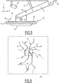
- the figure 3 shows a detail view of the feed pad 32 including a vibration sensor 34.
- the feed pad 32 comprises for example a sole 52 and a lever 54.
- the sole 52 comprises a lower surface 56 of contact with the supply rail. 22.
- the lever 54 has two ends, articulated respectively to the sole 52 and to the body 30 of the car 28.
- the supply pad 32 further comprises an actuator 58 connected to the lever 54 and allowing to move the sole 52 vertically, so as to separate it or bring it closer to the supply rail 22.
- the vibration sensor 34 comprises at least one accelerometer 60, 62.
- the vibration sensor 34 is formed of two accelerometers 60 and 62. Each of said accelerometers is located near one end of the sole 52 in the X direction.
- the vibration sensor 34 comprises an accelerometer in the middle of the sole 52 in the direction X.
- Each accelerometer 60, 62 is able to measure vibrations of the sole 52, in particular in the X, Y and Z directions.
- the lever 54 comprises a device 63 for evaluating the stresses and / or the vertical and transverse forces.
- Said evaluation device 63 comprises for example at least one accelerometer and / or at least one strain gauge.
- the lever 54 is for example equipped with a first strain gauge in an upper part and with a second strain gauge in a lower part.
- the evaluation device 63 is provided with means of communication with the computer 40.
- the vehicle 16 moves on the railway circuit 12.
- the detector 36 determines the spatial coordinates of said vehicle 16 at several successive instants t i during said movement (step 100).
- the sensor 34 measures the vibrations of the feed pad 32 (step 102).
- the speed sensor 39 simultaneously measures the speed of movement of the vehicle 16.
- the at least one camera 38 records video of the movement of the pad 32 relative to the body 30 or to the supply rail 22.
- the level of vibrations measured by the sensor 34 depends in particular on the state of the supply rail 22. For example, if said rail is misaligned at a junction 64 ( figure 2 ) between a conductive section 24 and an insulating section 26, the pad 32 undergoes a shock while passing in contact with said junction. This shock results in a high level of measured vibrations.
- the value V i corresponds to a vector, each column of which corresponds to the measurements of said accelerometers 60 and 62. Subsequently, these measurements are for example averaged.
- the method preferably comprises a step in which the measured vibration values V i are then subjected to a segmentation step (step 106).
- a segmentation step For example, a graphical representation of the function [measurement instant (t ⁇ ) / measured vibration (V ⁇ )] is converted by the computer 40 into segments separated by inflection points, according to a segmentation model. Each value V i is then replaced by a modified value V ' ⁇ .
- a method involving a segmentation step is for example described in the document WO2010 / 043951 .
- the program 48 then associates each vibration value V i or V ' i with the corresponding spatial coordinates C i , in particular acquired during the same instant t i (step 108).
- a kilometer point of the vehicle 16 on the track is calculated from the speed of said vehicle.
- the mileage point is the number of kilometers traveled by the vehicle on the track from a given landmark.
- the spatial coordinates C 1 are advantageously adjusted using the kilometer point: the spatial coordinates C 1 make it possible, for example, to generally know the path of the vehicle and the kilometer point the precise location of said vehicle on the lane corresponding to the path.
- Each value C i is then replaced by a modified value C ' ⁇ .
- the program 48 compares the vibration values V i or V ′ i with a threshold value V S stored in the program 48. Said vibration values V i or V ′ i are then classified into two groups: the “normal values” and the values of the vibration. “Abnormal values”, respectively lower and higher than the threshold value V S (step 110).
- the program 48 determines the spatial coordinates C i or C ′ i corresponding to “abnormal values” of vibration (step 112).
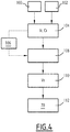
- this determination step comprises the production of a graphical representation of the type map 70 of railway circuit 12, as shown on figure 5 .
- the rail circuit 12 corresponds to the tram network of a city.
- the map 70 is for example displayed on the screen 46 of the computer 40.
- the map 70 shows in a visually different manner the portions of the railway circuit 12 corresponding to the “normal values” and to the “abnormal values” of vibration.
- the “normal value” portions 72 and the “abnormal value” portions 74 are indicated by different colors.
- the location of the abnormal vibration zones on a map of the railway circuit 12 then makes it possible to quickly send an intervention team to the places concerned, in particular to correct the alignment of the sections at the junctions 64.
- the program 48 stores several threshold values, for example two threshold values V S1 and V S2 with V S1 ⁇ V S2 .
- This variant makes it possible to classify the vibration values V i or V ′ i into three groups, for example “normal values”, “priority 1 abnormal values” and “priority 2 abnormal values”.
- This variant makes it possible to rank the priority levels of maintenance interventions on the rail circuit 12.
- the computer 40 analyzes in parallel the video recorded by the camera 38.
- the computer 40 detects, for example, any vertical jump of the shoe or any movement of the shoe in the transverse direction Y.
- the computer 40 analyzes in parallel the stresses and / or the vertical and transverse forces of the shoe 32, communicated by the evaluation device 63.
- the geometry of the track can present hard points, in particular in the needle passage. , which leads to generating significant forces on the lever 54 of the pad, in particular in the event of partial blocking thereof.
- the evaluation device 63 makes it possible in particular to detect a defect in the lever 54 before it breaks and / or to understand the cause of the break, if applicable.
- the method described above is advantageously implemented in the test phase of the railway circuit 12 to detect installation problems of the power supply device 14.
- the method is also implemented in the use phase, in order to deploy the maintenance teams on the network.
- several tram units usually circulating on the rail circuit 12 are equipped with sensors 34, 36, such as the vehicle 16 described above.
- the state of the network is updated in real time.
Landscapes
- Engineering & Computer Science (AREA)
- Mechanical Engineering (AREA)
- Power Engineering (AREA)
- Transportation (AREA)
- Train Traffic Observation, Control, And Security (AREA)
- Current-Collector Devices For Electrically Propelled Vehicles (AREA)
- Platform Screen Doors And Railroad Systems (AREA)
- Electric Propulsion And Braking For Vehicles (AREA)
- Vehicle Cleaning, Maintenance, Repair, Refitting, And Outriggers (AREA)
Claims (9)
- Verfahren zur Wartung einer Vorrichtung (14) zur Versorgung mit elektrischer Energie über den Boden für ein Transport-Fahrzeug (16), wobei die Vorrichtung aufweist:- eine Schiene (22) zur elektrischen Versorgung über den Boden, wobei die besagte Schiene zur elektrischen Versorgung elektrisch leitende Segmente (24) und elektrisch isolierende Segmente (26) aufweist, die abwechselnd und im Wesentlichen fluchtend sind,
wobei sich die Schiene zur elektrischen Versorgung zwischen zwei Lauf-Schienen (18) für das Transport-Fahrzeug (16) erstrecken,- eine Vorrichtung (36) zur Erfassung von räumlichen Koordinaten, und- einen Versorgungs-Schuh (32),
wobei die besagte Vorrichtung zur Erfassung (36) und der besagte Versorgungs-Schuh (32) das gleiche Transport-Fahrzeug (16) ausstatten,
wobei der Versorgungs-Schuh imstande ist, gegen die Schiene zur Versorgung zu schleifen während einer Verlagerung des besagten Fahrzeugs entlang besagter Schiene zur elektrischen Versorgung,- wobei der Versorgungs-Schuh aufweist
einen Vibrationen-Sensor (34, 60, 62) für den Schuh im Kontakt mit der Schiene zur elektrischen Versorgung,- wobei die Vorrichtung zur Versorgung (14) ferner wenigstens eine Kamera (38) aufweist, die ermöglicht, eine Positionierung des Versorgungs-Schuhs (32) bezüglich der Schiene (22) zur Versorgung oder bezüglich eines Gehäusekastens des Fahrzeugs zu visualisieren, und wobei- das Verfahren die folgenden Schritte aufweist:- Verlagern des Transport-Fahrzeugs entlang der Schiene zur elektrischen Versorgung,- während des besagten Verlagerns, Messen von Vibrationen des Versorgungs-Schuhs (100) und simultanes Erfassen von räumlichen Koordinaten des Fahrzeugs (102), dann- Vergleichen (110) der gemessenen Vibrationen des Versorgungs-Schuhs mit einem Schwellenwert, und- Ermitteln (112) der räumlichen Koordinaten, die zu Vibrationen korrespondieren, die größer als der besagte Schwellenwert sind, und- parallel dazu, Aufnehmen eines Videos mittels der Kamera (38), Analysieren des besagten Videos, um einen vertikalen Sprung des Schuhs oder einen Ausschlag des Schuhs entlang einer Richtung (Y) senkrecht zur Verlagerung des Fahrzeugs zu erfassen, und Korrelieren einer Vibration des Schuhs, die größer ist als der Schwellenwert, gemessen mittels des Vibrationen-Sensors, mit dem besagten Sprung oder dem besagten Ausschlag des Schuhs. - Verfahren zur Wartung gemäß Anspruch 1, aufweisend, zwischen den Schritten des Messens der Vibrationen (100) und des Vergleichens mit dem Schwellenwert (110), einen Schritt des Segmentierens (106) der gemessenen Vibrationen.
- Verfahren zur Wartung gemäß Anspruch 1 oder Anspruch 2, wobei der Schritt (112) des Erfassens der räumlichen Koordinaten, die zu den Vibrationen korrespondieren, die größer als der Schwellenwert sind, aufweist ein grafisches Repräsentieren (70) der Schiene zur elektrischen Versorgung, bei welchem die besagten räumlichen Koordinaten durch einen visuellen Marker (74) angegeben werden.
- Vorrichtung (14) zur Versorgung mit elektrischer Energie über den Boden für ein Transport-Fahrzeug (16), wobei die Vorrichtung aufweist:- eine Schiene (22) zur elektrischen Versorgung über den Boden, wobei die besagte Schiene zur elektrischen Versorgung elektrisch leitende Segmente (24) und elektrisch isolierende Segmente (26) aufweist, die abwechselnd und im Wesentlichen fluchtend sind,
wobei die Schiene zur elektrischen Versorgung dazu bestimmt ist, sich zwischen zwei Lauf-Schienen (18) für ein Fahrzeug zu erstrecken,- eine Vorrichtung (36) zur Erfassung von räumlichen Koordinaten eines Fahrzeugs, und- einen Versorgungs-Schuh (32) für ein Fahrzeug, der imstande ist, gegen die Schiene zur Versorgung zu schleifen während einer Verlagerung des besagten Fahrzeugs entlang besagter Schiene,
wobei die besagte Vorrichtung zur Erfassung (36) und der besagte Versorgungs-Schuh (32) dazu bestimmt sind, das gleiche Transport-Fahrzeug (16) auszustatten,
wobei bei der Vorrichtung zur Versorgung (14)- der Versorgungs-Schuh aufweist einen Vibrationen-Sensor (34, 60, 62) für den Schuh im Kontakt mit der Schiene zur Versorgung,- die Vorrichtung zur Versorgung ferner aufweist wenigstens eine Kamera (38), die ermöglicht, eine Positionierung des Versorgungs-Schuhs (32) bezüglich der Schiene (22) zur Versorgung oder bezüglich eines Gehäusekastens des Fahrzeugs zu visualisieren, und- die Vorrichtung zur Versorgung aufweist Mittel (40, 48) zum Durchführen eines Verfahrens gemäß einem der vorhergehenden Ansprüche. - Vorrichtung zur Versorgung gemäß Anspruch 4, wobei der Vibrationen-Sensor für den Versorgungs-Schuh einen Beschleunigungsmesser (60, 62) aufweist.
- Vorrichtung zur Versorgung gemäß Anspruch 5, wobei der Versorgungs-Schuh aufweist wenigstes zwei Beschleunigungsmesser (60, 62), wobei jeder entlang einer Verlagerungs-Richtung (X) des Fahrzeugs nahe einem Ende des Schuhs angeordnet ist.
- Vorrichtung zur Versorgung gemäß Anspruch 5, wobei der Versorgungs-Schuh eine Sohle (52) und wenigstens einen Beschleunigungsmesser (34, 60, 62) aufweist, der entlang einer Verlagerungs-Richtung (X) des Fahrzeugs mitten auf der Sohle (52) angeordnet ist.
- Vorrichtung zur Versorgung gemäß irgendeinem der Ansprüche 5 bis 7, wobei der Versorgungs-Schuh eine Sohle (52) und einen Hebel (54) aufweist, wobei der Hebel (54) aufweist eine Vorrichtung (63) zur Ermittlung von vertikalen und transversalen Spannungen und/oder Kräften, wobei die Vorrichtung zur Ermittlung aufweist wenigstens einen Beschleunigungsmesser und/oder wenigstens einen Dehnungsmessstreifen.
- Einrichtung (10) für ein Transport-Fahrzeug, aufweisend:- eine Vorrichtung zur Versorgung (14) mit elektrischer Energie über den Boden gemäß einem der Ansprüche 4 bis 8,- ein Transport-Fahrzeug (16), das mit der Vorrichtung zur Erfassung (36) und dem Versorgungs-Schuh (32) der besagten Vorrichtung zur Versorgung ausgestattet ist, und- zwei Lauf-Schienen (18), die beiderseits der Schiene zur Versorgung angeordnet sind,wobei das Transport-Fahrzeug ausgestattet ist mit Mitteln (27) zur Verlagerung auf den besagten Lauf-Schienen.
Applications Claiming Priority (1)
| Application Number | Priority Date | Filing Date | Title |
|---|---|---|---|
| FR1750671A FR3062361B1 (fr) | 2017-01-27 | 2017-01-27 | Procede de maintenance d'un dispositif d'alimentation par le sol pour vehicule de type tramway |
Publications (2)
| Publication Number | Publication Date |
|---|---|
| EP3354510A1 EP3354510A1 (de) | 2018-08-01 |
| EP3354510B1 true EP3354510B1 (de) | 2021-09-22 |
Family
ID=58547683
Family Applications (1)
| Application Number | Title | Priority Date | Filing Date |
|---|---|---|---|
| EP18153699.6A Active EP3354510B1 (de) | 2017-01-27 | 2018-01-26 | Wartungsverfahren einer vorrichtung zur stromzuführung über den boden für fahrzeugs vom typ strassenbahn |
Country Status (5)
| Country | Link |
|---|---|
| US (1) | US10683022B2 (de) |
| EP (1) | EP3354510B1 (de) |
| AU (1) | AU2018200512B2 (de) |
| ES (1) | ES2897398T3 (de) |
| FR (1) | FR3062361B1 (de) |
Cited By (1)
| Publication number | Priority date | Publication date | Assignee | Title |
|---|---|---|---|---|
| US20210221245A1 (en) * | 2018-06-01 | 2021-07-22 | Vivarail Ltd. | Rail transport vehicle electric energy storage and charging system |
Families Citing this family (11)
| Publication number | Priority date | Publication date | Assignee | Title |
|---|---|---|---|---|
| FR3084301B1 (fr) | 2018-07-27 | 2020-10-23 | Mersen France Sb Sas | Dispositif de captage de courant electrique pour un vehicule ferroviaire |
| DE102018133402B4 (de) * | 2018-12-21 | 2025-03-20 | Paul Vahle Gmbh & Co. Kg | Optische berührungslose parametrische Zustandskontrolle von Stromabnehmern und Schleifleitungsanlagen |
| DK3741606T3 (da) * | 2019-05-24 | 2022-05-23 | Siemens Ag | Indretning og fremgangsmåde til registrering af slitage på et transportsystem med glidekontakter |
| US11414002B2 (en) | 2019-09-25 | 2022-08-16 | The Boeing Company | Systems, methods, and apparatus for high-traffic density air transportation |
| US11989033B2 (en) | 2019-09-25 | 2024-05-21 | The Boeing Company | Systems, methods, and apparatus for high-traffic density personalized transportation |
| US11586222B2 (en) * | 2019-09-25 | 2023-02-21 | The Boeing Company | Systems, methods, and apparatus for high-traffic density transportation pathways |
| US11501933B2 (en) * | 2019-09-27 | 2022-11-15 | Apple Inc. | Strain sensing key membrane |
| CN112141175B (zh) * | 2020-09-24 | 2022-10-21 | 广西交控智维科技发展有限公司 | 轨道交通运维系统及方法 |
| CN112249093B (zh) * | 2020-09-24 | 2022-10-21 | 广西交控智维科技发展有限公司 | 轨道交通运维系统及方法 |
| US12187139B2 (en) * | 2021-06-15 | 2025-01-07 | Liebherr Mining Equipment Newport News Co. | Trolley system |
| EP4543705A2 (de) * | 2022-06-22 | 2025-04-30 | First Greater Western Limited | Stromsammelschuhvorrichtung |
Family Cites Families (16)
| Publication number | Priority date | Publication date | Assignee | Title |
|---|---|---|---|---|
| DE133422C (de) | ||||
| DD133422A1 (de) * | 1977-09-01 | 1979-01-03 | Creuzburg,Wolfgang,Dd | Verfahren einsatz eines schienengebundenen messfahrzeuges fuer strassenbahnfahrleitungen |
| FR2779392B1 (fr) * | 1998-06-04 | 2004-01-23 | Cegelec Sa | Systeme d'alimentation par le sol pour vehicule electrique et vehicule equipe pour utiliser un tel systeme |
| JP2000079839A (ja) * | 1998-06-24 | 2000-03-21 | West Japan Railway Co | 衝撃計測装置 |
| FR2791929B1 (fr) | 1999-04-07 | 2004-09-10 | Soc Gle Techniques Etudes | Dispositif de detection de presence de vehicule a fiabilite amelioree |
| FR2800020B1 (fr) * | 1999-10-25 | 2003-10-03 | Alstom | Systeme d'alimentation statique par le sol pour vehicule electrique et vehicule electrique destine a etre alimente au moyen d'un tel systeme d'alimentation |
| DE20205710U1 (de) * | 2002-04-11 | 2002-08-14 | Fahrleitungsbau GmbH, 45329 Essen | Stromabnehmer |
| JP4415330B2 (ja) * | 2006-04-14 | 2010-02-17 | 株式会社日立プラントテクノロジー | 電車線離線検知装置及び電車線離線検知方法 |
| US8825239B2 (en) * | 2010-05-19 | 2014-09-02 | General Electric Company | Communication system and method for a rail vehicle consist |
| US8655517B2 (en) * | 2010-05-19 | 2014-02-18 | General Electric Company | Communication system and method for a rail vehicle consist |
| JP2008285118A (ja) * | 2007-05-21 | 2008-11-27 | Toshiba Corp | 鉄道設備の異常診断計測システム |
| GB2463693A (en) * | 2008-09-19 | 2010-03-24 | Bombardier Transp Gmbh | A system for transferring electric energy to a vehicle |
| GB2463692A (en) * | 2008-09-19 | 2010-03-24 | Bombardier Transp Gmbh | An arrangement for providing a vehicle with electric energy |
| CA2734642C (en) | 2008-10-14 | 2018-03-13 | Schlumberger Canada Limited | System and method for online automation |
| US8473128B2 (en) * | 2010-05-19 | 2013-06-25 | L.B. Foster Rail Technologies Canada, Ltd. | Optimizing rail track performance |
| US20130063282A1 (en) * | 2010-05-31 | 2013-03-14 | Central Signal, Llc | Roadway detection |
-
2017
- 2017-01-27 FR FR1750671A patent/FR3062361B1/fr not_active Expired - Fee Related
-
2018
- 2018-01-23 AU AU2018200512A patent/AU2018200512B2/en active Active
- 2018-01-26 US US15/881,429 patent/US10683022B2/en active Active
- 2018-01-26 EP EP18153699.6A patent/EP3354510B1/de active Active
- 2018-01-26 ES ES18153699T patent/ES2897398T3/es active Active
Cited By (2)
| Publication number | Priority date | Publication date | Assignee | Title |
|---|---|---|---|---|
| US20210221245A1 (en) * | 2018-06-01 | 2021-07-22 | Vivarail Ltd. | Rail transport vehicle electric energy storage and charging system |
| US11904707B2 (en) * | 2018-06-01 | 2024-02-20 | First Greater Western Limited | Rail transport vehicle electric energy storage and charging system |
Also Published As
| Publication number | Publication date |
|---|---|
| FR3062361A1 (fr) | 2018-08-03 |
| ES2897398T3 (es) | 2022-03-01 |
| FR3062361B1 (fr) | 2020-08-14 |
| BR102018001706A8 (pt) | 2022-11-16 |
| US20180215401A1 (en) | 2018-08-02 |
| US10683022B2 (en) | 2020-06-16 |
| BR102018001706A2 (pt) | 2018-12-04 |
| AU2018200512B2 (en) | 2022-06-02 |
| AU2018200512A1 (en) | 2018-08-16 |
| EP3354510A1 (de) | 2018-08-01 |
Similar Documents
| Publication | Publication Date | Title |
|---|---|---|
| EP3354510A1 (de) | Wartungsverfahren einer vorrichtung zur stromzuführung über den boden für fahrzeugs vom typ strassenbahn | |
| EP2760724B1 (de) | Verfahren und vorrichtung zur erkennung der verfügbarkeit des gleises für ein spurgebundenes fahrzeug | |
| CN104050811B (zh) | 激光机动车分型系统及方法 | |
| US20180222504A1 (en) | Location based railway anomaly detection | |
| US20140152814A1 (en) | System for Imaging and Measuring Rail Deflection | |
| EP4308909A1 (de) | System und verfahren zur automatischen überwachung des strassenzustands | |
| KR102267901B1 (ko) | 노면 상태 추정 장치 및 이를 이용한 노면 상태 추정 방법 | |
| JP4692517B2 (ja) | 鉄道車両用脱線防止ガードの敷設位置診断方法 | |
| GB2408570A (en) | Current collector for electricl vehicle | |
| TW201204619A (en) | Traveling vehicle system and self-diagnosis method for the traveling vehicle system | |
| US10940876B2 (en) | Route examination system | |
| WO2019117796A1 (en) | Detection of maintenance status for a pantograph and/or a contact wire | |
| WO2018178097A1 (fr) | Dispositif de détection de défauts d'un rail et procédé de détection associé | |
| MX2007000578A (es) | Aparato para detectar movimiento de lazo y angulo de ataque del eje con sus ruedas de un vehiculo ferroviario. | |
| JP2010236875A (ja) | 構造体変状検知システム | |
| JP2019049952A (ja) | 情報処理システム、情報処理装置、道路状況検知方法およびプログラム | |
| KR101619790B1 (ko) | 열차 차륜 찰상 검지 시스템 및 방법 | |
| EP2389302A2 (de) | Verfahren zur präventiven erkennung und zur diagnose des ursprungs von kontaktfehlern zwischen einer stromversorgungsleitung und einem entlang dieser leitung beweglichen leitfähigen element | |
| GB2559166A (en) | Inductive system for determination of overhead electrical contact wire's wear and end-of-life | |
| CN110104533A (zh) | 自动扶梯或自动人行道的故障识别系统及方法 | |
| JP6030787B2 (ja) | 温度異常検出システム、温度異常検出方法 | |
| US9956972B2 (en) | Detection of dynamic train-to-rail shunting performance | |
| Gooneratne et al. | Smartphone-based road condition monitoring: a feasibility study | |
| TW201811588A (zh) | 礙子檢測裝置及礙子檢測方法 | |
| BR102018001706B1 (pt) | Método para a manutenção de um dispositivo de fornecimento de energia ao nível do solo para um veículo de transporte, dispositivo de fornecimento de energia ao nível do solo para um veículo de transporte e instalação para um veículo de transporte |
Legal Events
| Date | Code | Title | Description |
|---|---|---|---|
| PUAI | Public reference made under article 153(3) epc to a published international application that has entered the european phase |
Free format text: ORIGINAL CODE: 0009012 |
|
| STAA | Information on the status of an ep patent application or granted ep patent |
Free format text: STATUS: THE APPLICATION HAS BEEN PUBLISHED |
|
| AK | Designated contracting states |
Kind code of ref document: A1 Designated state(s): AL AT BE BG CH CY CZ DE DK EE ES FI FR GB GR HR HU IE IS IT LI LT LU LV MC MK MT NL NO PL PT RO RS SE SI SK SM TR |
|
| AX | Request for extension of the european patent |
Extension state: BA ME |
|
| STAA | Information on the status of an ep patent application or granted ep patent |
Free format text: STATUS: REQUEST FOR EXAMINATION WAS MADE |
|
| 17P | Request for examination filed |
Effective date: 20190107 |
|
| RBV | Designated contracting states (corrected) |
Designated state(s): AL AT BE BG CH CY CZ DE DK EE ES FI FR GB GR HR HU IE IS IT LI LT LU LV MC MK MT NL NO PL PT RO RS SE SI SK SM TR |
|
| STAA | Information on the status of an ep patent application or granted ep patent |
Free format text: STATUS: EXAMINATION IS IN PROGRESS |
|
| RIC1 | Information provided on ipc code assigned before grant |
Ipc: B61L 27/00 20060101ALI20200406BHEP Ipc: B60M 1/04 20060101ALI20200406BHEP Ipc: B60L 5/42 20060101AFI20200406BHEP Ipc: B61L 23/04 20060101ALI20200406BHEP Ipc: B60M 1/36 20060101ALI20200406BHEP Ipc: B60M 1/10 20060101ALI20200406BHEP |
|
| 17Q | First examination report despatched |
Effective date: 20200512 |
|
| GRAP | Despatch of communication of intention to grant a patent |
Free format text: ORIGINAL CODE: EPIDOSNIGR1 |
|
| STAA | Information on the status of an ep patent application or granted ep patent |
Free format text: STATUS: GRANT OF PATENT IS INTENDED |
|
| INTG | Intention to grant announced |
Effective date: 20210428 |
|
| GRAS | Grant fee paid |
Free format text: ORIGINAL CODE: EPIDOSNIGR3 |
|
| GRAA | (expected) grant |
Free format text: ORIGINAL CODE: 0009210 |
|
| STAA | Information on the status of an ep patent application or granted ep patent |
Free format text: STATUS: THE PATENT HAS BEEN GRANTED |
|
| AK | Designated contracting states |
Kind code of ref document: B1 Designated state(s): AL AT BE BG CH CY CZ DE DK EE ES FI FR GB GR HR HU IE IS IT LI LT LU LV MC MK MT NL NO PL PT RO RS SE SI SK SM TR |
|
| REG | Reference to a national code |
Ref country code: GB Ref legal event code: FG4D Free format text: NOT ENGLISH |
|
| REG | Reference to a national code |
Ref country code: IE Ref legal event code: FG4D Free format text: LANGUAGE OF EP DOCUMENT: FRENCH |
|
| REG | Reference to a national code |
Ref country code: DE Ref legal event code: R096 Ref document number: 602018023792 Country of ref document: DE |
|
| REG | Reference to a national code |
Ref country code: CH Ref legal event code: EP Ref country code: AT Ref legal event code: REF Ref document number: 1432070 Country of ref document: AT Kind code of ref document: T Effective date: 20211015 |
|
| REG | Reference to a national code |
Ref country code: LT Ref legal event code: MG9D |
|
| REG | Reference to a national code |
Ref country code: NL Ref legal event code: MP Effective date: 20210922 |
|
| PG25 | Lapsed in a contracting state [announced via postgrant information from national office to epo] |
Ref country code: NO Free format text: LAPSE BECAUSE OF FAILURE TO SUBMIT A TRANSLATION OF THE DESCRIPTION OR TO PAY THE FEE WITHIN THE PRESCRIBED TIME-LIMIT Effective date: 20211222 Ref country code: BG Free format text: LAPSE BECAUSE OF FAILURE TO SUBMIT A TRANSLATION OF THE DESCRIPTION OR TO PAY THE FEE WITHIN THE PRESCRIBED TIME-LIMIT Effective date: 20211222 Ref country code: LT Free format text: LAPSE BECAUSE OF FAILURE TO SUBMIT A TRANSLATION OF THE DESCRIPTION OR TO PAY THE FEE WITHIN THE PRESCRIBED TIME-LIMIT Effective date: 20210922 Ref country code: RS Free format text: LAPSE BECAUSE OF FAILURE TO SUBMIT A TRANSLATION OF THE DESCRIPTION OR TO PAY THE FEE WITHIN THE PRESCRIBED TIME-LIMIT Effective date: 20210922 Ref country code: SE Free format text: LAPSE BECAUSE OF FAILURE TO SUBMIT A TRANSLATION OF THE DESCRIPTION OR TO PAY THE FEE WITHIN THE PRESCRIBED TIME-LIMIT Effective date: 20210922 Ref country code: FI Free format text: LAPSE BECAUSE OF FAILURE TO SUBMIT A TRANSLATION OF THE DESCRIPTION OR TO PAY THE FEE WITHIN THE PRESCRIBED TIME-LIMIT Effective date: 20210922 Ref country code: HR Free format text: LAPSE BECAUSE OF FAILURE TO SUBMIT A TRANSLATION OF THE DESCRIPTION OR TO PAY THE FEE WITHIN THE PRESCRIBED TIME-LIMIT Effective date: 20210922 |
|
| REG | Reference to a national code |
Ref country code: AT Ref legal event code: MK05 Ref document number: 1432070 Country of ref document: AT Kind code of ref document: T Effective date: 20210922 |
|
| PG25 | Lapsed in a contracting state [announced via postgrant information from national office to epo] |
Ref country code: LV Free format text: LAPSE BECAUSE OF FAILURE TO SUBMIT A TRANSLATION OF THE DESCRIPTION OR TO PAY THE FEE WITHIN THE PRESCRIBED TIME-LIMIT Effective date: 20210922 Ref country code: GR Free format text: LAPSE BECAUSE OF FAILURE TO SUBMIT A TRANSLATION OF THE DESCRIPTION OR TO PAY THE FEE WITHIN THE PRESCRIBED TIME-LIMIT Effective date: 20211223 |
|
| REG | Reference to a national code |
Ref country code: ES Ref legal event code: FG2A Ref document number: 2897398 Country of ref document: ES Kind code of ref document: T3 Effective date: 20220301 |
|
| PG25 | Lapsed in a contracting state [announced via postgrant information from national office to epo] |
Ref country code: AT Free format text: LAPSE BECAUSE OF FAILURE TO SUBMIT A TRANSLATION OF THE DESCRIPTION OR TO PAY THE FEE WITHIN THE PRESCRIBED TIME-LIMIT Effective date: 20210922 |
|
| PG25 | Lapsed in a contracting state [announced via postgrant information from national office to epo] |
Ref country code: IS Free format text: LAPSE BECAUSE OF FAILURE TO SUBMIT A TRANSLATION OF THE DESCRIPTION OR TO PAY THE FEE WITHIN THE PRESCRIBED TIME-LIMIT Effective date: 20220122 Ref country code: SK Free format text: LAPSE BECAUSE OF FAILURE TO SUBMIT A TRANSLATION OF THE DESCRIPTION OR TO PAY THE FEE WITHIN THE PRESCRIBED TIME-LIMIT Effective date: 20210922 Ref country code: RO Free format text: LAPSE BECAUSE OF FAILURE TO SUBMIT A TRANSLATION OF THE DESCRIPTION OR TO PAY THE FEE WITHIN THE PRESCRIBED TIME-LIMIT Effective date: 20210922 Ref country code: PT Free format text: LAPSE BECAUSE OF FAILURE TO SUBMIT A TRANSLATION OF THE DESCRIPTION OR TO PAY THE FEE WITHIN THE PRESCRIBED TIME-LIMIT Effective date: 20220124 Ref country code: PL Free format text: LAPSE BECAUSE OF FAILURE TO SUBMIT A TRANSLATION OF THE DESCRIPTION OR TO PAY THE FEE WITHIN THE PRESCRIBED TIME-LIMIT Effective date: 20210922 Ref country code: NL Free format text: LAPSE BECAUSE OF FAILURE TO SUBMIT A TRANSLATION OF THE DESCRIPTION OR TO PAY THE FEE WITHIN THE PRESCRIBED TIME-LIMIT Effective date: 20210922 Ref country code: EE Free format text: LAPSE BECAUSE OF FAILURE TO SUBMIT A TRANSLATION OF THE DESCRIPTION OR TO PAY THE FEE WITHIN THE PRESCRIBED TIME-LIMIT Effective date: 20210922 Ref country code: CZ Free format text: LAPSE BECAUSE OF FAILURE TO SUBMIT A TRANSLATION OF THE DESCRIPTION OR TO PAY THE FEE WITHIN THE PRESCRIBED TIME-LIMIT Effective date: 20210922 Ref country code: AL Free format text: LAPSE BECAUSE OF FAILURE TO SUBMIT A TRANSLATION OF THE DESCRIPTION OR TO PAY THE FEE WITHIN THE PRESCRIBED TIME-LIMIT Effective date: 20210922 |
|
| REG | Reference to a national code |
Ref country code: DE Ref legal event code: R097 Ref document number: 602018023792 Country of ref document: DE |
|
| PG25 | Lapsed in a contracting state [announced via postgrant information from national office to epo] |
Ref country code: DK Free format text: LAPSE BECAUSE OF FAILURE TO SUBMIT A TRANSLATION OF THE DESCRIPTION OR TO PAY THE FEE WITHIN THE PRESCRIBED TIME-LIMIT Effective date: 20210922 |
|
| PLBE | No opposition filed within time limit |
Free format text: ORIGINAL CODE: 0009261 |
|
| STAA | Information on the status of an ep patent application or granted ep patent |
Free format text: STATUS: NO OPPOSITION FILED WITHIN TIME LIMIT |
|
| REG | Reference to a national code |
Ref country code: DE Ref legal event code: R119 Ref document number: 602018023792 Country of ref document: DE |
|
| 26N | No opposition filed |
Effective date: 20220623 |
|
| PG25 | Lapsed in a contracting state [announced via postgrant information from national office to epo] |
Ref country code: MC Free format text: LAPSE BECAUSE OF FAILURE TO SUBMIT A TRANSLATION OF THE DESCRIPTION OR TO PAY THE FEE WITHIN THE PRESCRIBED TIME-LIMIT Effective date: 20210922 |
|
| REG | Reference to a national code |
Ref country code: CH Ref legal event code: PL |
|
| GBPC | Gb: european patent ceased through non-payment of renewal fee |
Effective date: 20220126 |
|
| PG25 | Lapsed in a contracting state [announced via postgrant information from national office to epo] |
Ref country code: LU Free format text: LAPSE BECAUSE OF NON-PAYMENT OF DUE FEES Effective date: 20220126 Ref country code: GB Free format text: LAPSE BECAUSE OF NON-PAYMENT OF DUE FEES Effective date: 20220126 Ref country code: DE Free format text: LAPSE BECAUSE OF NON-PAYMENT OF DUE FEES Effective date: 20220802 |
|
| PG25 | Lapsed in a contracting state [announced via postgrant information from national office to epo] |
Ref country code: SI Free format text: LAPSE BECAUSE OF FAILURE TO SUBMIT A TRANSLATION OF THE DESCRIPTION OR TO PAY THE FEE WITHIN THE PRESCRIBED TIME-LIMIT Effective date: 20210922 |
|
| PG25 | Lapsed in a contracting state [announced via postgrant information from national office to epo] |
Ref country code: LI Free format text: LAPSE BECAUSE OF NON-PAYMENT OF DUE FEES Effective date: 20220131 Ref country code: CH Free format text: LAPSE BECAUSE OF NON-PAYMENT OF DUE FEES Effective date: 20220131 |
|
| PG25 | Lapsed in a contracting state [announced via postgrant information from national office to epo] |
Ref country code: IT Free format text: LAPSE BECAUSE OF FAILURE TO SUBMIT A TRANSLATION OF THE DESCRIPTION OR TO PAY THE FEE WITHIN THE PRESCRIBED TIME-LIMIT Effective date: 20210922 Ref country code: IE Free format text: LAPSE BECAUSE OF NON-PAYMENT OF DUE FEES Effective date: 20220126 |
|
| P01 | Opt-out of the competence of the unified patent court (upc) registered |
Effective date: 20230823 |
|
| PG25 | Lapsed in a contracting state [announced via postgrant information from national office to epo] |
Ref country code: HU Free format text: LAPSE BECAUSE OF FAILURE TO SUBMIT A TRANSLATION OF THE DESCRIPTION OR TO PAY THE FEE WITHIN THE PRESCRIBED TIME-LIMIT; INVALID AB INITIO Effective date: 20180126 |
|
| PG25 | Lapsed in a contracting state [announced via postgrant information from national office to epo] |
Ref country code: SM Free format text: LAPSE BECAUSE OF FAILURE TO SUBMIT A TRANSLATION OF THE DESCRIPTION OR TO PAY THE FEE WITHIN THE PRESCRIBED TIME-LIMIT Effective date: 20210922 Ref country code: MK Free format text: LAPSE BECAUSE OF FAILURE TO SUBMIT A TRANSLATION OF THE DESCRIPTION OR TO PAY THE FEE WITHIN THE PRESCRIBED TIME-LIMIT Effective date: 20210922 Ref country code: CY Free format text: LAPSE BECAUSE OF FAILURE TO SUBMIT A TRANSLATION OF THE DESCRIPTION OR TO PAY THE FEE WITHIN THE PRESCRIBED TIME-LIMIT Effective date: 20210922 |
|
| PG25 | Lapsed in a contracting state [announced via postgrant information from national office to epo] |
Ref country code: TR Free format text: LAPSE BECAUSE OF FAILURE TO SUBMIT A TRANSLATION OF THE DESCRIPTION OR TO PAY THE FEE WITHIN THE PRESCRIBED TIME-LIMIT Effective date: 20210922 |
|
| PG25 | Lapsed in a contracting state [announced via postgrant information from national office to epo] |
Ref country code: MT Free format text: LAPSE BECAUSE OF FAILURE TO SUBMIT A TRANSLATION OF THE DESCRIPTION OR TO PAY THE FEE WITHIN THE PRESCRIBED TIME-LIMIT Effective date: 20210922 |
|
| REG | Reference to a national code |
Ref country code: ES Ref legal event code: PC2A Owner name: ALSTOM HOLDINGS Effective date: 20250310 |
|
| REG | Reference to a national code |
Ref country code: BE Ref legal event code: PD Owner name: ALSTOM HOLDINGS; FR Free format text: DETAILS ASSIGNMENT: CHANGE OF OWNER(S), ASSIGNMENT; FORMER OWNER NAME: ALSTOM TRANSPORT TECHNOLOGIES Effective date: 20241025 |
|
| PGFP | Annual fee paid to national office [announced via postgrant information from national office to epo] |
Ref country code: ES Payment date: 20260227 Year of fee payment: 9 |
|
| PGFP | Annual fee paid to national office [announced via postgrant information from national office to epo] |
Ref country code: BE Payment date: 20260121 Year of fee payment: 9 |
|
| PGFP | Annual fee paid to national office [announced via postgrant information from national office to epo] |
Ref country code: FR Payment date: 20260123 Year of fee payment: 9 |