EP3354508A1 - Tankentlüftungssystem für eine verbrennungskraftmaschine und verfahren zur regenerierung eines sorptionsspeichers - Google Patents
Tankentlüftungssystem für eine verbrennungskraftmaschine und verfahren zur regenerierung eines sorptionsspeichers Download PDFInfo
- Publication number
- EP3354508A1 EP3354508A1 EP17208287.7A EP17208287A EP3354508A1 EP 3354508 A1 EP3354508 A1 EP 3354508A1 EP 17208287 A EP17208287 A EP 17208287A EP 3354508 A1 EP3354508 A1 EP 3354508A1
- Authority
- EP
- European Patent Office
- Prior art keywords
- air flow
- ventilation system
- tank
- purge air
- tank ventilation
- Prior art date
- Legal status (The legal status is an assumption and is not a legal conclusion. Google has not performed a legal analysis and makes no representation as to the accuracy of the status listed.)
- Granted
Links
Images


Classifications
-
- F—MECHANICAL ENGINEERING; LIGHTING; HEATING; WEAPONS; BLASTING
- F02—COMBUSTION ENGINES; HOT-GAS OR COMBUSTION-PRODUCT ENGINE PLANTS
- F02M—SUPPLYING COMBUSTION ENGINES IN GENERAL WITH COMBUSTIBLE MIXTURES OR CONSTITUENTS THEREOF
- F02M25/00—Engine-pertinent apparatus for adding non-fuel substances or small quantities of secondary fuel to combustion-air, main fuel or fuel-air mixture
- F02M25/08—Engine-pertinent apparatus for adding non-fuel substances or small quantities of secondary fuel to combustion-air, main fuel or fuel-air mixture adding fuel vapours drawn from engine fuel reservoir
- F02M25/089—Layout of the fuel vapour installation
-
- B—PERFORMING OPERATIONS; TRANSPORTING
- B60—VEHICLES IN GENERAL
- B60K—ARRANGEMENT OR MOUNTING OF PROPULSION UNITS OR OF TRANSMISSIONS IN VEHICLES; ARRANGEMENT OR MOUNTING OF PLURAL DIVERSE PRIME-MOVERS IN VEHICLES; AUXILIARY DRIVES FOR VEHICLES; INSTRUMENTATION OR DASHBOARDS FOR VEHICLES; ARRANGEMENTS IN CONNECTION WITH COOLING, AIR INTAKE, GAS EXHAUST OR FUEL SUPPLY OF PROPULSION UNITS IN VEHICLES
- B60K15/00—Arrangement in connection with fuel supply of combustion engines or other fuel consuming energy converters, e.g. fuel cells; Mounting or construction of fuel tanks
- B60K15/03—Fuel tanks
- B60K15/035—Fuel tanks characterised by venting means
- B60K15/03504—Fuel tanks characterised by venting means adapted to avoid loss of fuel or fuel vapour, e.g. with vapour recovery systems
-
- B—PERFORMING OPERATIONS; TRANSPORTING
- B60—VEHICLES IN GENERAL
- B60K—ARRANGEMENT OR MOUNTING OF PROPULSION UNITS OR OF TRANSMISSIONS IN VEHICLES; ARRANGEMENT OR MOUNTING OF PLURAL DIVERSE PRIME-MOVERS IN VEHICLES; AUXILIARY DRIVES FOR VEHICLES; INSTRUMENTATION OR DASHBOARDS FOR VEHICLES; ARRANGEMENTS IN CONNECTION WITH COOLING, AIR INTAKE, GAS EXHAUST OR FUEL SUPPLY OF PROPULSION UNITS IN VEHICLES
- B60K15/00—Arrangement in connection with fuel supply of combustion engines or other fuel consuming energy converters, e.g. fuel cells; Mounting or construction of fuel tanks
- B60K15/03—Fuel tanks
- B60K15/035—Fuel tanks characterised by venting means
- B60K15/03519—Valve arrangements in the vent line
-
- F—MECHANICAL ENGINEERING; LIGHTING; HEATING; WEAPONS; BLASTING
- F02—COMBUSTION ENGINES; HOT-GAS OR COMBUSTION-PRODUCT ENGINE PLANTS
- F02D—CONTROLLING COMBUSTION ENGINES
- F02D41/00—Electrical control of supply of combustible mixture or its constituents
- F02D41/0025—Controlling engines characterised by use of non-liquid fuels, pluralities of fuels, or non-fuel substances added to the combustible mixtures
- F02D41/003—Adding fuel vapours, e.g. drawn from engine fuel reservoir
- F02D41/0032—Controlling the purging of the canister as a function of the engine operating conditions
- F02D41/004—Control of the valve or purge actuator, e.g. duty cycle, closed loop control of position
-
- F—MECHANICAL ENGINEERING; LIGHTING; HEATING; WEAPONS; BLASTING
- F02—COMBUSTION ENGINES; HOT-GAS OR COMBUSTION-PRODUCT ENGINE PLANTS
- F02M—SUPPLYING COMBUSTION ENGINES IN GENERAL WITH COMBUSTIBLE MIXTURES OR CONSTITUENTS THEREOF
- F02M25/00—Engine-pertinent apparatus for adding non-fuel substances or small quantities of secondary fuel to combustion-air, main fuel or fuel-air mixture
- F02M25/08—Engine-pertinent apparatus for adding non-fuel substances or small quantities of secondary fuel to combustion-air, main fuel or fuel-air mixture adding fuel vapours drawn from engine fuel reservoir
- F02M25/0809—Judging failure of purge control system
- F02M25/0827—Judging failure of purge control system by monitoring engine running conditions
-
- F—MECHANICAL ENGINEERING; LIGHTING; HEATING; WEAPONS; BLASTING
- F02—COMBUSTION ENGINES; HOT-GAS OR COMBUSTION-PRODUCT ENGINE PLANTS
- F02M—SUPPLYING COMBUSTION ENGINES IN GENERAL WITH COMBUSTIBLE MIXTURES OR CONSTITUENTS THEREOF
- F02M25/00—Engine-pertinent apparatus for adding non-fuel substances or small quantities of secondary fuel to combustion-air, main fuel or fuel-air mixture
- F02M25/08—Engine-pertinent apparatus for adding non-fuel substances or small quantities of secondary fuel to combustion-air, main fuel or fuel-air mixture adding fuel vapours drawn from engine fuel reservoir
- F02M25/0836—Arrangement of valves controlling the admission of fuel vapour to an engine, e.g. valve being disposed between fuel tank or absorption canister and intake manifold
-
- F—MECHANICAL ENGINEERING; LIGHTING; HEATING; WEAPONS; BLASTING
- F02—COMBUSTION ENGINES; HOT-GAS OR COMBUSTION-PRODUCT ENGINE PLANTS
- F02M—SUPPLYING COMBUSTION ENGINES IN GENERAL WITH COMBUSTIBLE MIXTURES OR CONSTITUENTS THEREOF
- F02M25/00—Engine-pertinent apparatus for adding non-fuel substances or small quantities of secondary fuel to combustion-air, main fuel or fuel-air mixture
- F02M25/08—Engine-pertinent apparatus for adding non-fuel substances or small quantities of secondary fuel to combustion-air, main fuel or fuel-air mixture adding fuel vapours drawn from engine fuel reservoir
- F02M25/0854—Details of the absorption canister
-
- B—PERFORMING OPERATIONS; TRANSPORTING
- B60—VEHICLES IN GENERAL
- B60K—ARRANGEMENT OR MOUNTING OF PROPULSION UNITS OR OF TRANSMISSIONS IN VEHICLES; ARRANGEMENT OR MOUNTING OF PLURAL DIVERSE PRIME-MOVERS IN VEHICLES; AUXILIARY DRIVES FOR VEHICLES; INSTRUMENTATION OR DASHBOARDS FOR VEHICLES; ARRANGEMENTS IN CONNECTION WITH COOLING, AIR INTAKE, GAS EXHAUST OR FUEL SUPPLY OF PROPULSION UNITS IN VEHICLES
- B60K15/00—Arrangement in connection with fuel supply of combustion engines or other fuel consuming energy converters, e.g. fuel cells; Mounting or construction of fuel tanks
- B60K15/03—Fuel tanks
- B60K2015/0319—Fuel tanks with electronic systems, e.g. for controlling fuelling or venting
-
- B—PERFORMING OPERATIONS; TRANSPORTING
- B60—VEHICLES IN GENERAL
- B60K—ARRANGEMENT OR MOUNTING OF PROPULSION UNITS OR OF TRANSMISSIONS IN VEHICLES; ARRANGEMENT OR MOUNTING OF PLURAL DIVERSE PRIME-MOVERS IN VEHICLES; AUXILIARY DRIVES FOR VEHICLES; INSTRUMENTATION OR DASHBOARDS FOR VEHICLES; ARRANGEMENTS IN CONNECTION WITH COOLING, AIR INTAKE, GAS EXHAUST OR FUEL SUPPLY OF PROPULSION UNITS IN VEHICLES
- B60K15/00—Arrangement in connection with fuel supply of combustion engines or other fuel consuming energy converters, e.g. fuel cells; Mounting or construction of fuel tanks
- B60K15/03—Fuel tanks
- B60K15/035—Fuel tanks characterised by venting means
- B60K15/03504—Fuel tanks characterised by venting means adapted to avoid loss of fuel or fuel vapour, e.g. with vapour recovery systems
- B60K2015/03514—Fuel tanks characterised by venting means adapted to avoid loss of fuel or fuel vapour, e.g. with vapour recovery systems with vapor recovery means
-
- B—PERFORMING OPERATIONS; TRANSPORTING
- B60—VEHICLES IN GENERAL
- B60K—ARRANGEMENT OR MOUNTING OF PROPULSION UNITS OR OF TRANSMISSIONS IN VEHICLES; ARRANGEMENT OR MOUNTING OF PLURAL DIVERSE PRIME-MOVERS IN VEHICLES; AUXILIARY DRIVES FOR VEHICLES; INSTRUMENTATION OR DASHBOARDS FOR VEHICLES; ARRANGEMENTS IN CONNECTION WITH COOLING, AIR INTAKE, GAS EXHAUST OR FUEL SUPPLY OF PROPULSION UNITS IN VEHICLES
- B60K15/00—Arrangement in connection with fuel supply of combustion engines or other fuel consuming energy converters, e.g. fuel cells; Mounting or construction of fuel tanks
- B60K15/03—Fuel tanks
- B60K15/035—Fuel tanks characterised by venting means
- B60K2015/03561—Venting means working at specific times
- B60K2015/03571—Venting during driving
-
- B—PERFORMING OPERATIONS; TRANSPORTING
- B60—VEHICLES IN GENERAL
- B60K—ARRANGEMENT OR MOUNTING OF PROPULSION UNITS OR OF TRANSMISSIONS IN VEHICLES; ARRANGEMENT OR MOUNTING OF PLURAL DIVERSE PRIME-MOVERS IN VEHICLES; AUXILIARY DRIVES FOR VEHICLES; INSTRUMENTATION OR DASHBOARDS FOR VEHICLES; ARRANGEMENTS IN CONNECTION WITH COOLING, AIR INTAKE, GAS EXHAUST OR FUEL SUPPLY OF PROPULSION UNITS IN VEHICLES
- B60K15/00—Arrangement in connection with fuel supply of combustion engines or other fuel consuming energy converters, e.g. fuel cells; Mounting or construction of fuel tanks
- B60K15/03—Fuel tanks
- B60K15/035—Fuel tanks characterised by venting means
- B60K2015/0358—Fuel tanks characterised by venting means the venting is actuated by specific signals or positions of particular parts
- B60K2015/03585—Fuel tanks characterised by venting means the venting is actuated by specific signals or positions of particular parts by gas pressure
Definitions
- the present invention relates to a tank ventilation system of an internal combustion engine having a tank which is connected via a tank vent with a Sorptions appointed for temporarily storing fuel from a tank ventilation flow, and a scavenge pump for supplying regenerated fuel from the Sorptions appointed via a purge air flow in an intake air flow to the internal combustion engine. Furthermore, the invention relates to a method for regenerating a Sorptions appointeds, which is part of such a tank ventilation system.
- tank ventilation systems or fuel evaporation restraint systems are provided to prevent fuel vapors from being released from the tank (fuel tank).
- a container with activated carbon (activated carbon trap, activated carbon filter, AKF for short) is used, which is connected via a line to the gas / vapor phase of the fuel tank and via another line or connection with the environment.
- the AKF When venting the tank, the AKF stores the fuel vapors that accumulate on the activated carbon (adsorption storage tank), thereby filtering the vent flow from the tank so that no hydrocarbons escape into the environment. Since AKF have only a limited capacity, they must be regenerated regularly. The fuel components deposited on the activated carbon are removed again. This is usually done by flushing the ACF with fresh air while driving. For this the AKF is over one further line usually connected to the intake of the engine, is sucked through the fresh air. The negative pressure also sucks fresh air through the AKF, which is enriched with fuel - this regenerates the activated carbon - which is then burned in the internal combustion engine.
- the activated carbon adsorption storage tank
- the intake (sub) pressure in the intake tract is often so low that it is not possible to adequately purge the AKF while driving.
- the generated purge air flow is too low.
- the purge air mass flow can vary greatly with the changing pressure level in the intake system.
- the (sub) pressure level causing the scavenging air flow depends very much on the respective driving situation or on the operating state of the internal combustion engine, a compressor and in particular an exhaust gas turbocharger arrangement with which most modern gasoline engines are provided.
- the purge air mass flow is adjusted by means of a so-called regeneration valve (also tank vent valve).
- This regeneration valve is arranged in a line which connects the activated carbon container with the suction pipe. If the regeneration valve releases the line between the AKF and the intake manifold while driving or during operation of the VKM, fresh air is sucked through the activated carbon. It absorbs the fuel absorbed there and leads it to combustion. In this case, the activated carbon of the activated carbon container is regenerated, so that the activated carbon of the activated carbon filter for newly evaporating fuel from the fuel tank is receptive again. This regeneration is done regularly.
- the loading or saturation level of the activated carbon filter can be determined.
- a motor control which can control the vent valve, and a ⁇ -regulating device for adjusting the supplied air-fuel mixture in the internal combustion engine
- a conveyor for example, a pump
- An inventive tank ventilation system of an internal combustion engine comprises a tank, which is connected via a tank vent with a Sorptions appointed (activated carbon filter, AKF) for temporarily storing fuel from a tank ventilation flow, a scavenge air pump, which generates a purge air flow, via the regenerated fuel from the Sorptions appointed into an intake air flow to Internal combustion engine is performed, wherein a controller is provided, which is designed to control the scavenging air pump such that the purging air flow in terms of its pressure, its mass and / or its volume is adjustable, so that a metering of the regenerated fuel via the scavenging air flow into the intake air flow takes place in accordance with an operating state of the internal combustion engine.
- Sorptions Grande activated carbon filter
- the purge air pump is not only used for pressure build-up or for volume delivery, but also for adjusting the purge air flow in terms of its pressure, its mass and / or its volume. This makes it possible to simplify the otherwise required controllable vent valve or its control. It may even be omitted altogether.
- the operating state of the internal combustion engine comprises a rotational speed and / or a load state.
- the scavenging air system can be optimally adapted to the operating condition of the internal combustion engine. It is not necessary to change the operating state of the internal combustion engine with regard to a required regeneration of the activated carbon filter, but the tank ventilation system adapts to the desired or (fuel) optimized operating state of the VKM.
- the intake air flow of the internal combustion engine is supplied via a compressor and the dosage is additionally or significantly determined according to an operating state of the compressor.
- This allows a pump operation that is controllable according to the activity of a temporary compressor.
- the performance of the purge air pump can be adapted to the compressor performance. Existing pressure gradients between the purge air line and the intake tract can be easily observed via the compressor operation (eg via its speed or power consumption).
- ATL exhaust gas turbocharger
- ATL are particularly suitable for high performance and low fuel consumption in relatively small-volume gasoline engines.
- a vote of the tank ventilation system on such internal combustion engines with exhaust gas turbocharger extends the possibilities to positively influence emission values, in particular HC emissions, without thereby restricts the regeneration of the AKF.
- scavenging air pumps are particularly effective because the pressure conditions for effective flushing are favorable (absolute pressure level in the scavenging air system low).
- the purge air pump comprises an electric drive, which is adjustable in terms of current and / or voltage depending on torque and / or speed via the controller.
- the metering takes place via the control of the electric drive.
- the setting of the scavenging air flow with respect to its pressure, its mass and / or its volume or a metering of the regenerated fuel is particularly easy to implement via the electrical supply values of the electric drive. This can be controlled for example simply by a current, a voltage and / or an excitation frequency.
- this control of the electric drive via a map.
- the operating conditions of the internal combustion engine and / or the compressor of a certain drive values of the electric drive are assigned.
- the scavenging air pump can thus also be controlled in the desired manner via complex operating state combinations (for example when a plurality of characteristic maps are combined).
- a pressure sensor for detecting the scavenging air pressure is arranged and the scavenging air flow is adjusted taking into account a pressure signal. This makes it possible to extend the control criteria for the purge air pump by a pressure value.
- the purge air flow is introduced via a shut-off and / or control valve in the intake air flow, which is controlled via the control and / or adjustable and adjustable by the purge air flow in terms of its pressure, its mass and / or its volume is.
- a regeneration of the activated charcoal filter can also be realized, for example, if the scavenge air pump is only to be flowed through passively (for example with a sufficiently high pressure gradient, in which no use of the pump is necessary. Such a pressure gradient can be given for example in MPI (Multi Point Injection) engines without turbocharger).
- An additional shut-off and / or control valve can then ensure that regeneration of the activated carbon filter is possible at least in certain operating states of the internal combustion engine.
- the scavenging air pump can be operated in a diagnostic conveying direction so that a tank tightness or leakage diagnosis can be carried out
- the field of use of the tank ventilation system according to the invention is expanded.
- a tank leak diagnostic device is a mandatory feature of a tank ventilation system. If the scavenging air pump can be operated in both directions, then this tank leak diagnosis or leak diagnosis can be integrated into the already existing system and possibly only has to be activated by control technology.
- Such a method allows on the one hand a simplified, improved and more differentiable scavenging air control for the reliable regeneration of a Sorptions Grandes and on the other hand, an exact dosage of the regenerated fuel flow into the internal combustion engine, as required for modern gasoline engines.
- Such a method which is extended by at least one of these measures, permits a further differentiated and thus possibly also further improved scavenging air control and metering of the regenerated fuel.
- a motor vehicle with a tank ventilation system according to the invention which is adapted to carry out the above-mentioned method, is improved with regard to its emission-related equipment and with regard to the optimal use of all available fuel components.
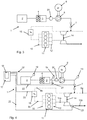
- FIG Fig. 1 A first embodiment of a tank ventilation system 1 according to the invention is shown in FIG Fig. 1 shown. It comprises a fuel tank or simply tank 2, a sorption storage 3, which is designed as activated carbon filter or activated carbon trap (also AKF), and comprises an activated carbon filling 4. Furthermore, a scavenging air pump 5 with an electric drive 6 is provided and optionally a shut-off and / or control valve 7. Tank 2, sorption storage 3, purge air pump 5 and optionally shut-off / control valve 7 are connected to one another via a tank vent line 8a or purge air line 8b.
- a tank vent line 8a or purge air line 8b A first embodiment of a tank ventilation system 1 according to the invention.
- the scavenging air line 8b opens into a first intake line section 9a (coming from an air filter, not shown) which opens via a second intake line section 9b and a third intake line section 9c via a distributor 10 into an internal combustion engine (VKM) 11 designed as a gasoline engine.
- VKM internal combustion engine
- the exhaust gases of the internal combustion engine 11 are guided via a manifold 12 into a first exhaust pipe section 13a and a second exhaust pipe section 13b.
- the activated carbon filter 3 is arranged between the tank ventilation line 8a and the scavenging air line 8b.
- the purge air pump 5 is disposed in the purge air line 8b between the activated carbon filter 3 and the first intake passage portion 9a.
- the optional shut-off / control valve 7 is shown here in the scavenging air line 8b between the purge air pump 5 and the first intake line section 9a. In an alternative embodiment, this optional shut-off / control valve 7 can also be provided between the activated carbon filter 3 and the purge air pump 5.
- an exhaust gas turbocharger (ATL) 14 is arranged, the compressor wheel 14a of which acts between the first and second intake pipe sections 9a, 9b.
- the turbine wheel 14b of the exhaust gas turbocharger 14 acts between the first and second exhaust pipe sections 13a and 13b.
- the throttle valve 15 acts the throttle valve 15, which regulates the intake air flow between the turbocharger 14 and the internal combustion engine 11.
- the tank ventilation system 1 acts as follows: If the pressure in the fuel tank 2 increases relative to the ambient pressure, the excess pressure is removed via the gas phase and the tank ventilation line 8a through the sorption reservoir (activated carbon filter) 3 via an exhaust air line 8c. The same thing happens when heat is supplied via an energy source 16 (e.g., by solar radiation or at high ambient temperature). The fuel in the tank 2 heats up and partially evaporates. In order to prevent an unacceptable pressure increase in the tank 2, the evaporated fuel is passed through the tank vent line 8a in the sorption 3, the fuel components are enriched in the activated carbon filling 4 and the cleaned exhaust air is discharged via the exhaust duct 8c to the environment.
- an energy source 16 e.g., by solar radiation or at high ambient temperature
- the electric drive 6 drives the scavenging air pump 5, a fresh air flow through the tank vent line 8a (possibly also through the tank 2) or via the then serving as air supply line 8c through the activated carbon 4 of the Activated carbon filter 3 passes.
- This scavenging air stream absorbs the fuel deposited in the activated carbon filter 3 and is introduced via the purge air pump 4 through the scavenging air line 8b into the first intake line section 9a (between the air filter and the compressor wheel 14a, not shown).
- the so enriched in the purging air stream with fuel intake air stream is compressed and fed via the second intake pipe section 9b (pressure tube) 9b, the throttle valve 15 and the third intake pipe section 9c (intake manifold) via the manifold 11 in the internal combustion engine 11, where he then along with the injected Primary fuel is burned / used.
- the purge air flow is adjusted by means of the purge air pump 5 and the electric drive 6 with respect to its pressure, its mass and / or its volume, with respect to an operating condition of the internal combustion engine 11.
- both the purge air volume (the flow) and the purge air pressure adjusted become.
- the regenerated fuel supplied via the scavenging air can also be metered in in the desired manner.
- a controller 17 which is connected both to the internal combustion engine 11 and to the scavenging air pump 5 or to the electric drive 6.
- the control of the scavenging air pump takes place, for example, according to the speed or the load of the internal combustion engine 11.
- one or more characteristic maps can be stored in the controller 17, which then corresponding operating states of the purge air pump (pressure, volume) or corresponding drive variables of the electric drive 6 (eg current, voltage, excitation frequency) are assigned.
- the purge air flow can also be controlled via an operating state of the exhaust gas turbocharger 14.
- the exhaust gas turbocharger 14 is coupled to the controller 17 via a rotational speed sensor, which then controls the scavenging air pump 5 or the electric drive 6, taking into account the rotational speed of the exhaust gas turbocharger.
- the different operating states of the exhaust-gas turbocharger can also be stored in characteristic diagrams in the controller 17 and thus serve as the basis for a supplementary map-controlled actuation of the scavenging air pump 5.
- the electric drive 6 is also controlled with respect to the transmitted to the purge air pump 5 torque and / or a desired speed via a supply current, a supply voltage and / or an excitation frequency. These quantities correlate with a desired purge air flow in terms of its pressure and volume (more precisely its volumetric flow).
- shut-off / control valve 7 can additionally be activated (for example as a continuously adjustable or interval-controllable solenoid valve).
- the control can take place, for example, via a pulse-width-modulated control signal which defines the opening cross-section or the opening / closing frequency.
- Fig. 2 shows a second embodiment of a tank ventilation system according to the invention, in which additionally in the tank, in the tank vent line 8a and 8b in the scavenging air line one (or more) pressure sensor (s) 19 is arranged, which emits a corresponding pressure signal to the controller 17 and the purge air additionally adjusted taking into account the recorded pressure signal.
- a pressure signal is helpful, for example, to accurately set or regulate a map-oriented control of the engine 6 and thus of the purge air pump 5 via an additional pressure signal before and / or behind the purge air pump.
- Fig. 3 shows a second embodiment in which a volumetric flow meter 20 is additionally provided between the activated carbon filter 3 and the purge air pump 5 in the scavenging air line 8b. Also, this volume flow meter outputs a volume flow signal to the controller 17, so that this adjusts the purge air pump 5 and thus the purge air flow, taking into account the volume flow signal (controls or regulates).
- Fig. 2 and Fig. 3 illustrated embodiments can also be combined with each other, so that both volume flow signals and pressure signals for controlling the purge air pump 5 and to adjust the purge air flow can be used.
- Both the volumetric flow meter 20 and the pressure sensor or sensors 19 can be supplemented by a temperature sensor 21 which is integrated into either the pressure sensor 19 or the volumetric flow meter 20 or can be provided as a separate temperature sensor 21 in the scavenging air line 8b or in the purge air pump 5 can and corresponding signals to the controller 17 supplies.
- Fig. 4 the controller 17 is shown with a map 18, via signal and control lines 22 with the essential components of the tank ventilation system 1 and the Combustion engine 11 is coupled and either receives signals or outputs control signals.
- the signals of the ⁇ probe 23 it is possible to take into account the regenerated fuel quantity in the fuel injection via a corresponding control of the purge air pump 5 or to adjust the purge air pump 5 so that the regenerated amount of fuel that is metered into the intake air, behaves constantly, so that eg the primary injection dosage by the metered amount of regeneration fuel during the regeneration process remains unaffected or is taken into account in the injection control.
- the system and method is also suitable for MPI gasoline engines.
- the point of introduction of the scavenging air line 8b into the intake line 9a, 9b, 9c is then to be provided in front of a throttle valve or in the intake manifold 9c.
- the scavenging air pump 5 is to be made correspondingly robust, so that it withstands the possibly high intake manifold vacuum and the consequent high pressure differences and is suitable for adjusting the purge air flow in the desired manner.
Landscapes
- Engineering & Computer Science (AREA)
- Chemical & Material Sciences (AREA)
- Combustion & Propulsion (AREA)
- Mechanical Engineering (AREA)
- General Engineering & Computer Science (AREA)
- Life Sciences & Earth Sciences (AREA)
- Sustainable Development (AREA)
- Sustainable Energy (AREA)
- Transportation (AREA)
- Supplying Secondary Fuel Or The Like To Fuel, Air Or Fuel-Air Mixtures (AREA)
Abstract
Description
- Die vorliegende Erfindung betrifft ein Tankentlüftungssystem einer Verbrennungskraftmaschine mit einem Tank, der über eine Tankentlüftung mit einem Sorptionsspeicher zum Zwischenspeichern von Kraftstoff aus einem Tankentlüftungsstrom verbunden ist, und einer Spülluftpumpe zum Zuführen von regeneriertem Kraftstoff aus dem Sorptionsspeicher über einen Spülluftstrom in einen Ansaugluftstrom zur Verbrennungskraftmaschine. Weiter betrifft die Erfindung ein Verfahren zum Regenerieren eines Sorptionsspeichers, der Bestandteil eines solchen Tankentlüftungssystems ist.
- Für Fahrzeuge, die einen Ottomotor als Verbrennungskraftmaschine (VKM) aufweisen, sind Tankentlüftungssysteme bzw. Kraftstoffverdunstungs-Rückhaltesysteme vorgesehen, um zu verhindern, dass aus dem Tank (Kraftstoffbehälter) Kraftstoffdämpfe freigesetzt werden.
- Insbesondere können solche Systeme dazu beitragen, die Kohlenwasserstoff(HC)-Emissionen zu senken. Aus technischer Sicht sind mehrere Anforderungen zu erfüllen: Zum einen muss gewährleistet sein, dass sich - zum Beispiel unter Wärmeeinstrahlung - der Innendruck eines Kraftstofftanks nicht unzulässig erhöht, und zum anderen muss sichergestellt werden, dass frei werdende Kraftstoffdämpfe zurückgehalten werden.
- Es muss also eine Entlüftungsmöglichkeit des Tanks geben und eine Einrichtung zum Zurückhalten der Kraftstoffdämpfe. Für diese Funktion wird im Allgemeinen ein Behälter mit Aktivkohle (Aktivkohlefalle, Aktivkohlefilter, kurz: AKF) verwendet, der über eine Leitung mit der Gas-/Dampfphase des Kraftstofftanks verbunden ist und über eine weitere Leitung oder einen Anschluss mit der Umgebung.
- Beim Entlüften des Tanks speichert der AKF die Kraftstoffdämpfe, die sich an der Aktivkohle anlagern (Adsorptionsspeicher), und filtert dabei den Entlüftungsstrom aus dem Tank, so dass keine Kohlenwasserstoffe in die Umgebung gelangen. Da AKF nur ein begrenztes Aufnahmevermögen haben, müssen sie regelmäßig regeneriert werden. Dabei werden die an der Aktivkohle angelagerten Kraftstoffbestandteile wieder abgelöst. Dies geschieht in der Regel durch die Spülung des AKF mit Frischluft während der Fahrt. Dazu ist der AKF über eine weitere Leitung in der Regel mit dem Ansaugtrakt des Motors verbunden, über den Frischluft angesaugt wird. Der Unterdruck saugt zusätzlich Frischluft durch den AKF, diese wird mit Kraftstoff angereichert - dabei wird die Aktivkohle regeneriert - der dann in der Verbrennungskraftmaschine verbrannt wird.
- Bei modernen Turboladermotoren ist jedoch der Ansaug(Unter-)druck im Ansaugtrakt oft so gering, dass keine ausreichende Spülung des AKF während des Fahrbetriebs möglich ist. Der erzeugte Spülluftstrom ist zu gering. Außerdem kann der Spülluftmassenstrom stark mit dem wechselnden Druckniveau im Ansaugtrakt schwanken. Das den Spülluftstrom bewirkende (Unter-)Druckniveau hängt sehr stark von der jeweiligen Fahrsituation bzw. vom Betriebszustand der Verbrennungskraftmaschine, eines Verdichters und insbesondere einer Abgasturboladeranordnung ab, mit der die meisten modernen Ottomotoren versehen sind.
- Bei den üblichen Tankentlüftungssystemen wird der Spülluftmassenstrom mithilfe eines sogenannten Regenerierventils (auch Tankentlüftungsventil) eingestellt. Dieses Regenerierventil ist in einer Leitung angeordnet, die den Aktivkohlebehälter mit dem Saugrohr verbindet. Gibt das Regenerierventil während der Fahrt bzw. beim Betrieb der VKM die Leitung zwischen dem AKF und dem Saugrohr frei, wird Frischluft durch die Aktivkohle gesaugt. Sie nimmt den dort absorbierten Kraftstoff auf und führt ihn der Verbrennung zu. Dabei wird die Aktivkohle des Aktivkohlebehälters regeneriert, damit die Aktivkohle des Aktivkohlefilters für neu ausdampfenden Kraftstoff aus dem Kraftstofftank wieder aufnahmefähig ist. Diese Regenerierung erfolgt regelmäßig.
- Unter Umständen ist es erforderlich, zur ausreichenden Regenerierung des Aktivkohlefilters den Betriebszustand der VKM zu verändern. Zum Beispiel muss bei Systemen mit Benzindirekteinspritzung im Schichtbetrieb, in dem der Druckunterschied zwischen Saugrohr und Umgebungsdruck sehr gering ist, in den Homogenbetrieb umgeschaltet werden.
- In Verbindung mit einer Motorsteuerung, welche das Entlüftungsventil ansteuern kann, und einer λ-Regelungseinrichtung zum Einstellen des zuzuführenden Luft-Kraftstoff-Gemisches in die Verbrennungskraftmaschine kann auch der Beladungs- bzw. Sättigungsgrad des Aktivkohlefilters ermittelt werden. So ein Ansatz ist aus der
DE 197 01 353 C1 bekannt. - Es gibt auch Systeme, bei denen zur zusätzlichen Förderung (Druckerhöhung) und für andere Aufgaben zwischen dem Aktivkohlefilter und dem Belüftungsventil eine Fördereinrichtung (zum Beispiel eine Pumpe) vorgesehen ist.
- Einen Ansatz, bei dem eine solche Pumpe auch dazu vorgesehen ist, eine Kraftstofftankleckdiagnose durchzuführen, ist aus der
DE 10 2010 064 239 A1 bekannt. Ein anderes System, bei dem eine Spülluftpumpe in Verbindung mit einem FSI-Motor verwendet wird, ist aus derDE 196 50 517 A1 bekannt. Bei diesem Konzept ist jedoch keine Abgasturboaufladung vorgesehen. - Bei den bekannten Systemen erfolgt die Einstellung (Steuerung bzw. Regelung) des Spülluftstroms über das Spülluftventil. Damit sind Steuerventile erforderlich, deren Durchlass in der Regel über ein Ansteuerungstastverhältnis eingestellt wird. Eine ergänzend vorgesehene Spülluftpumpe arbeitet dabei - gegebenenfalls auch völlig unabhängig von den notwendigen Druck- oder Volumenstromanforderungen - bei einer festen Nennlast.
- Insbesondere beim Zuführen des Spülluftstroms in den Ansaugtrakt in Strömungsrichtung hinter dem Abgasturbolader sind dazu relativ hohe Drücke erforderlich. Es gibt auch Betriebszustände, bei denen die Nennlast der Pumpe für eine maximale Spülung zu gering ist - der Spülvorgang dauert länger, als es der Betriebszustand der VKM erlauben würde - oder der Druck bzw. der Volumenstrom ist sehr hoch und wird durch das Spülluftventil stark begrenzt - die Pumpe arbeitet unwirtschaftlich.
- Es besteht also die Aufgabe, ein verbessertes Tankentlüftungssystem bereitzustellen, das wenigstens einen Teil der oben dargestellten Probleme löst.
- Diese Aufgabe wird durch das erfindungsgemäße Tankentlüftungssystem gemäß Anspruch 1 und durch das erfindungsgemäße Verfahren zur Regeneration eines Sorptionsspeichers gemäß Anspruch 14 gelöst. Weitere vorteilhafte Ausgestaltungen der Erfindung ergeben sich aus den Unteransprüchen und der folgenden Beschreibung bevorzugter Ausführungsbeispiele der vorliegenden Erfindung.
- Ein erfindungsgemäßes Tankentlüftungssystem einer Verbrennungskraftmaschine umfasst einen Tank, der über eine Tankentlüftung mit einem Sorptionsspeicher (Aktivkohlefilter, AKF) zum Zwischenspeichern von Kraftstoff aus einem Tankentlüftungsstrom verbunden ist, eine Spülluftpumpe, die einen Spülluftstrom erzeugt, über den regenerierter Kraftstoff aus dem Sorptionsspeicher in einen Ansaugluftstrom zur Verbrennungskraftmaschine geführt wird, wobei eine Steuerung vorgesehen ist, die dazu ausgebildet ist, die Spülluftpumpe derart anzusteuern, dass der Spülluftstrom hinsichtlich seines Drucks, seiner Masse und/oder seines Volumens einstellbar ist, so dass eine Dosierung des regenerierten Kraftstoffs über den Spülluftstrom in den Ansaugluftstrom entsprechend einem Betriebszustand der Verbrennungskraftmaschine erfolgt.
- Bei so einem System wird die Spülluftpumpe nicht nur zum Druckaufbau bzw. zur Volumenförderung genutzt, sondern auch zum Einstellen des Spülluftstroms hinsichtlich seines Drucks, seiner Masse und/oder seines Volumens. Damit ist es möglich, das sonst erforderliche regelbare Entlüftungsventil bzw. dessen Ansteuerung zu vereinfachen. Gegebenenfalls kann es sogar ganz entfallen.
- Dadurch, dass der Betrieb der Spülluftpumpe auf einen Betriebszustand der Verbrennungskraftmaschine abgestimmt wird, kann eine gezielte Dosierung des regenerierten Kraftstoffs über den Spülluftstrom in den Ansaugluftstrom bzw. den Ansaugtrakt über die Einstellung (Regelung und/oder Steuerung) der Spülluftpumpe erfolgen. Dies ist bei modernen Motoren besonders wichtig, da sonst die erforderlichen engen Grenzwerte von Abgaswerten nur schwer eingehalten werden können. Die genaue Kraftstoffdosierung, die nicht nur über den unmittelbar eingespritzten Kraftstoff erfolgt, sondern auch über den zeitweise zusätzlich zugeführten Kraftstoff aus dem Tankentlüftungssystem, ist mit so einem System möglich.
- Dabei gibt es Ausführungen, bei denen der Betriebszustand der Verbrennungskraftmaschine eine Drehzahl und/oder einen Lastzustand umfasst. Damit kann das Spülluftsystem optimal auf den Betriebszustand der Verbrennungskraftmaschine abgestimmt werden. Es ist nicht erforderlich, den Betriebszustand der Verbrennungskraftmaschine im Hinblick auf eine erforderliche Regenerierung des Aktivkohlefilters zu verändern, sondern das Tankentlüftungssystem passt sich an den gewünschten oder (verbrauchs-)optimierten Betriebszustand der VKM an.
- Bei einer anderen Ausführung wird der Ansaugluftstrom der Verbrennungskraftmaschine über einen Verdichter zugeführt und die Dosierung wird zusätzlich oder maßgeblich entsprechend einem Betriebszustand des Verdichters festgelegt. Dies erlaubt einen Pumpenbetrieb, der entsprechend der Aktivität eines zeitweise arbeitenden Verdichters steuerbar bzw. einstellbar ist. Damit kann die Leistung der Spülluftpumpe an die Verdichterleistung angepasst werden. Vorhandene Druckgefälle zwischen der Spülluftleitung und dem Ansaugtrakt können so einfach über den Verdichterbetrieb (z.B. über dessen Drehzahl oder Leistungsaufnahme) beachtet werden.
- Dabei gibt es Ausführungen, bei denen der Verdichter als Abgasturbolader (ATL) ausgebildet ist. ATL sind besonders geeignet, bei relativ kleinvolumigen Ottomotoren hohe Leistungen und eine verbrauchsarme Kraftstoffnutzung zu ermöglichen. Eine Abstimmung des Tankentlüftungssystems auf solche Verbrennungskraftmaschinen mit Abgasturbolader erweitert die Möglichkeiten, um Emissionswerte, insbesondere HC-Emissionswerte, positiv zu beeinflussen, ohne dass dabei die Regenerierung des AKF eingeschränkt wird.
- Bei Ausführungen, bei denen der Spülluftstrom bezogen auf die Ansaugluftstromrichtung vor dem Verdichter bzw. dem Abgasturbolader dem Ansaugluftstrom zugeführt wird, sind Spülluftpumpen besonders effektiv, da die Druckverhältnisse für ein effektives Spülen günstig sind (absolutes Druckniveau im Spülluftsystem niedrig). Bei so einer Ausführung ist es möglich, über die Spülluftpumpe auch bei geringem Druckunterschied zwischen der Umgebung und dem Ansaugrohrbereich vor dem Abgasturbolader zuverlässig eine Regenerierung des Aktivkohlefilters durchzuführen. Eine Anpassung des Betriebszustands der Verbrennungskraftmaschine ist nicht erforderlich.
- Es gibt Ausführungen, bei der die Spülluftpumpe einen elektrischen Antrieb umfasst, der strom- und/oder spannungsabhängig hinsichtlich Drehmoment und/oder Drehzahl über die Steuerung einstellbar ist. Die Dosierung erfolgt über die Ansteuerung des elektrischen Antriebs. Die Einstellung des Spülluftstroms hinsichtlich seines Drucks, seiner Masse und/oder seines Volumens bzw. eine Dosierung des regenerierten Kraftstoffs ist besonders einfach über die elektrischen Versorgungswerte des elektrischen Antriebs zu realisieren. Dieser kann beispielsweise einfach über eine Stromstärke, eine Spannung und/oder über eine Erregerfrequenz angesteuert werden.
- Dabei gibt es Ausführungen, bei denen diese Ansteuerung des elektrischen Antriebs über ein Kennfeld erfolgt. So können z.B. die Betriebszustände der Verbrennungskraftmaschine und/oder die eines Verdichters bestimmten Ansteuerungswerten des elektrischen Antriebs zugeordnet werden. Die Spülluftpumpe ist so auch über komplexe Betriebszustandskombinationen (z.B. bei Kombination mehrerer Kennfelder) in der gewünschten Weise ansteuerbar.
- Es gibt Ausführungen, bei denen die Dosierung unter Berücksichtigung eines λ-Werts erfolgt, der von einer in einem Abgasstrom angeordneten λ-Sonde erfasst wird. Die Nutzung einer λ-Steuerung ermöglicht es, den Spülluftstrom nicht nur hinsichtlich der Regenerierung des Aktivkohlefilters einzustellen, sondern auch hinsichtlich einer äußerst exakten Kraftstoffdosierung.
- Es gibt Ausführungen, wobei in einer Spülluftleitung ein Drucksensor zum Erfassen des Spülluftdrucks angeordnet ist und der Spülluftstrom unter Berücksichtigung eines Drucksignals eingestellt ist. Damit ist es möglich, die Ansteuerungskriterien für die Spülluftpumpe durch einen Druckwert zu erweitern.
- Gleiches gilt für Ausführungen, bei denen in einer Spülluftleitung ein Volumenstromsensor zum Erfassen eines Spülluftvolumenstroms angeordnet ist und der Spülluftstrom unter Berücksichtigung eines Volumenstromsignals einstellbar ist. Auch so eine zusätzliche Berücksichtigung von Ist-Werten im Spülluftstrom erlaubt eine weitere Differenzierung der Ansteuerung der Spülluftpumpe.
- Gleiches gilt für Lösungen, bei denen zusätzlich auch eine Temperatur erfasst wird. Mit der teilweisen bzw. gleichzeitigen Erfassung aller gasstromrelevanten Größen wie Druck, Temperatur und Volumen lässt sich eine maximal differenzierte Ansteuerung der Spülluftpumpe realisieren.
- Es gibt auch Ausführungen, bei denen alternativ bzw. ergänzend solche Sensoren (Druck, Volumen, Temperatur) im Tank selbst, im AKF, in einer Entlüftungsleitung oder auch im Ansaugtrakt vorgesehen sind, und deren Signale für die Ansteuerung Spülluftpumpe verwendet werden.
- Es gibt Ausführungen, bei denen der Spülluftstrom über ein Absperr- und/oder Regelventil in den Ansaugluftstrom eingeleitet wird, das über die Steuerung ansteuer- und/oder einstellbar ist und über das der Spülluftstrom hinsichtlich seines Drucks, seiner Masse und/oder seines Volumens einstellbar ist. Neben der Einstellung über die Spülluftpumpe lässt sich beispielsweise bei zusätzlicher Verwendung eines Absperr- und/oder Regelventils eine Regenerierung des Aktivkohlefilters auch dann realisieren, wenn die Spülluftpumpe nur passiv durchströmt werden soll (beispielsweise bei einem ausreichend hohen Druckgefälle, bei dem kein Pumpeneinsatz erforderlich ist. So ein Druckgefälle kann z.B. bei MPI (Multi Point Injection)-Motoren ohne Abgasturbolader gegeben sein). Ein zusätzliches Absperr- und/oder Regelventil kann dann sicherstellen, dass wenigstens in bestimmten Betriebszuständen der Verbrennungskraftmaschine eine Regenerierung des Aktivkohlefilters möglich ist.
- Bei Ausführungen, bei denen die Spülluftpumpe in eine Diagnoseförderrichtung betreibbar ist, so dass eine Tankdichtigkeits- bzw. -leckagediagnose durchführbar ist, erweitert den Einsatzbereich des erfindungsgemäßen Tankentlüftungssystems. In einigen Regionen (zum Beispiel Nordamerika) ist eine Tankdichtigkeitsdiagnoseeinrichtung ein vorgeschriebenes Merkmal eines Tankentlüftungssystems. Ist die Spülluftpumpe in beide Richtungen betreibbar, so kann diese Tankdichtigkeitsdiagnose oder auch Leckdiagnose in das bereits vorhandene System integriert werden und muss gegebenenfalls nur steuerungstechnisch aktiviert werden.
- Es gibt auch ein Verfahren zum Regenerieren eines Sorptionsspeichers, das die folgenden Schritte aufweist:
- Bereitstellen eines Tankentlüftungssystems mit wenigstens einem der oben beschriebenen Merkmale;
- Erfassen eines Betriebszustands der Verbrennungskraftmaschine;
- Ansteuern der Spülluftpumpe und Einstellen des Spülluftstroms entsprechend einem Betriebszustand der Verbrennungskraftmaschine und/oder eines Verdichters;
- Regenerieren des Kraftstoffs aus dem Sorptionsspeicher und
- Dosieren des regenerierten Kraftstoffs über den Spülluftstrom in den Ansaugluftstrom, wobei das Einstellen des Spülluftstroms und Dosieren des regenerierten Kraftstoffs unter Berücksichtigung eines der folgenden Parameter erfolgt: λ-Wert, Spülluftdruck, Spülluftvolumen, Spüllufttemperatur.
- So ein Verfahren ermöglicht einerseits eine vereinfachte, verbesserte und weiter differenzierbare Spülluftsteuerung zur zuverlässigen Regenerierung eines Sorptionsspeichers und andererseits eine exakte Dosierung des regenerierten Kraftstoffstroms in die Verbrennungskraftmaschine, wie sie für moderne Ottomotoren erforderlich ist.
- Optional kann zusätzlich wenigstens einer der folgenden Schritte vorgesehen sein:
- Erfassen eines Drucksignals in der Spülluftleitung,
- Erfassen eines Volumenstromsignals in der Spülluftleitung,
- Erfassen eines Temperatursignals in der Spülluftleitung
- Erfassen eines λ-Werts in einem Abgasleitungsabschnitt,
- Ansteuern eines elektrischen Antriebs der Spülluftpumpe über einen Versorgungsstrom, eine Versorgungsspannung und/oder eine Erregerfrequenz,
- Ansteuern eines Absperr-/Regelventil.
- So ein um wenigstens eine dieser Maßnahmen erweitertes Verfahren erlaubt eine weiter differenzierte und damit ggf. auch weiter verbesserte Spülluftsteuerung und Dosierung des regenerierten Kraftstoffs.
- Ein Kraftfahrzeug mit einem erfindungsgemäßen Tankentlüftungssystem, das dazu eingerichtet ist, das oben angegebene Verfahren auszuführen, ist hinsichtlich seiner emissionstechnischen Ausrüstung und hinsichtlich der optimalen Nutzung aller verfügbaren Kraftstoffkomponenten verbessert.
- Ausführungsbeispiele der Erfindung werden nun beispielhaft und unter Bezugnahme auf die beigefügte Zeichnung beschrieben. Darin zeigt:
- Fig. 1
- ein erstes Ausführungsbeispiel eines erfindungsgemäßen Tankentlüftungssystems einer Verbrennungskraftmaschine,
- Fig. 2
- ein zweites Ausführungsbeispiel eines erfindungsgemäßen Tankentlüftungssystems,
- Fig. 3
- ein drittes Ausführungsbeispiel eines erfindungsgemäßen Tankentlüftungssystems,
- Fig. 4
- ein viertes Ausführungsbeispiel eines erfindungsgemäßen Tankentlüftungssystems, bei dem auch die Steuerung angezeigt ist, und
- Fig. 5
- ein Ablaufdiagramm eines erfindungsgemäßen Verfahrens zum Regenerieren eines Sorptionsspeichers.
- Ein erstes Ausführungsbeispiel eines erfindungsgemäßen Tankentlüftungssystems 1 ist in
Fig. 1 dargestellt. Es umfasst einen Kraftstoffbehälter oder einfach Tank 2, einen Sorptionsspeicher 3, der als Aktivkohlefilter bzw. Aktivkohlefalle (auch AKF) ausgebildet ist, und eine Aktivkohlefüllung 4 umfasst. Weiter ist eine Spülluftpumpe 5 mit einem elektrischen Antrieb 6 vorgesehen sowie optional ein Absperr- und/oder Regelventil 7. Tank 2, Sorptionsspeicher 3, Spülluftpumpe 5 und gegebenenfalls Absperr-/Regelventil 7 sind über eine Tankentlüftungsleitung 8a bzw. Spülluftleitung 8b miteinander verbunden. - Die Spülluftleitung 8b mündet in einen ersten Ansaugleitungsabschnitt 9a (von einem nicht dargestellten Luftfilter kommend), der über einen zweiten Ansaugleitungsabschnitt 9b und einen dritten Ansaugleitungsabschnitt 9c über einen Verteiler 10 in eine als Ottomotor ausgebildete Verbrennungskraftmaschine (VKM) 11 mündet. Die Abgase der Verbrennungskraftmaschine 11 werden über einen Krümmer 12 in einen ersten Abgasleitungsabschnitt 13a und einen zweiten Abgasleitungsabschnitt 13b geführt.
- Der Aktivkohlefilter 3 ist zwischen der Tankentlüftungsleitung 8a und der Spülluftleitung 8b angeordnet. Die Spülluftpumpe 5 ist in der Spülluftleitung 8b zwischen dem Aktivkohlefilter 3 und dem ersten Ansaugleitungsabschnitt 9a angeordnet.
- Das optionale Absperr-/Regelventil 7 ist hier in der Spülluftleitung 8b zwischen der Spülluftpumpe 5 und dem ersten Ansaugleitungsabschnitt 9a dargestellt. In einer alternativen Ausführung kann dieses optionale Absperr-/Regelventil 7 auch zwischen dem Aktivkohlefilter 3 und der Spülluftpumpe 5 vorgesehen werden.
- Zwischen dem ersten Ansaugleitungsabschnitt 9a und dem zweiten Ansaugleitungsabschnitt 9b (auch Druckrohr genannt) ist ein Abgasturbolader (ATL) 14 angeordnet, dessen Verdichterrad 14a zwischen dem ersten und zweiten Ansaugleitungsabschnitt 9a, 9b wirkt. Das Turbinenrad 14b des Abgasturboladers 14 wirkt zwischen dem ersten und zweiten Abgasleitungsabschnitt 13a und 13b.
- Zwischen dem zweiten Ansaugleitungsabschnitt 9b und dem dritten Ansaugleitungsabschnitt 9c (auch Saugrohr genannt) wirkt die Drosselklappe 15, welche den Ansaugluftstrom zwischen dem Turbolader 14 und der Verbrennungskraftmaschine 11 reguliert.
- Das Tankentlüftungssystem 1 wirkt folgendermaßen: Steigt im Kraftstoffbehälter 2 der Druck relativ zum Umgebungsdruck, wird der Überdruck über die Gasphase und die Tankentlüftungsleitung 8a durch den Sorptionsspeicher (Aktivkohlefilter) 3 über eine Abluftleitung 8c abgeführt. Das Gleiche passiert, wenn über eine Energiequelle 16 Wärme zugeführt wird (z.B. durch Sonneneinstrahlung oder bei hoher Umgebungstemperatur). Der im Tank 2 vorhandene Kraftstoff erwärmt sich und verdampft teilweise. Um eine unzulässige Druckerhöhung im Tank 2 zu verhindern, wird der verdunstete Kraftstoff durch die Tankentlüftungsleitung 8a in den Sorptionsspeicher 3 geleitet, die Kraftstoffbestandteile werden in der Aktivkohlefüllung 4 angereichert und die gereinigte Abluft wird über die Abluftleitung 8c an die Umgebung abgegeben.
- Ist nun das Aufnahmevermögen des Aktivkohlefilters 3 mit Kraftstoff erschöpft, muss dieser regeneriert werden. Dies geschieht während des Betriebs der Verbrennungskraftmaschine 11. Dabei treibt der elektrische Antrieb 6 die Spülluftpumpe 5 an, die einen Frischluftstrom über die Tankentlüftungsleitung 8a (gegebenenfalls auch durch den Tank 2) bzw. über die dann als Zuluftleitung dienende Abluftleitung 8c durch die Aktivkohlefüllung 4 des Aktivkohlefilters 3 leitet. Dieser Spülluftstrom nimmt dabei den im Aktivkohlefilter 3 angelagerten Kraftstoff auf und wird über die Spülluftpumpe 4 durch die Spülluftleitung 8b in den ersten Ansaugleitungsabschnitt 9a (zwischen dem nicht dargestellten Luftfilter und dem Verdichterrad 14a) eingeleitet. Der so über den Spülluftstrom mit Kraftstoff angereicherte Ansaugluftstrom wird verdichtet und über den zweiten Ansaugleitungsabschnitt 9b (Druckrohr) 9b, die Drosselklappe 15 und den dritten Ansaugleitungsabschnitt 9c (Saugrohr) über den Verteiler 11 in die Verbrennungskraftmaschine 11 geführt, wo er dann zusammen mit dem eingespritzten Primärkraftstoff verbrannt/genutzt wird.
- Der Spülluftstrom wird dabei mittels der Spülluftpumpe 5 bzw. des elektrischen Antriebs 6 hinsichtlich seines Drucks, seiner Masse und/oder seines Volumens eingestellt, und zwar hinsichtlich eines Betriebszustands der Verbrennungskraftmaschine 11. Damit kann sowohl die Spülluftmenge (der Volumenstrom) als auch der Spülluftdruck eingestellt werden. Weiter kann so auch der über die Spülluft zugeführte regenerierte Kraftstoff in gewünschter Weise eindosiert werden.
- Dazu dient eine Steuerung 17 (siehe
Fig. 4 ), die sowohl mit der Verbrennungskraftmaschine 11 als auch mit der Spülluftpumpe 5 bzw. mit dem elektrischen Antrieb 6 verbunden ist. Die Steuerung der Spülluftpumpe erfolgt beispielsweise entsprechend der Drehzahl bzw. der Last der Verbrennungskraftmaschine 11. Dazu können in der Steuerung 17 ein oder mehrere Kennfelder (z.B. mit Last-/Drehzahldaten) hinterlegt sein, die dann entsprechenden Betriebszuständen der Spülluftpumpe (Druck, Volumen) bzw. entsprechenden Ansteuerungsgrößen des elektrischen Antriebs 6 (z.B. Strom, Spannung, Erregerfrequenz) zugeordnet werden. - Ergänzend kann der Spülluftstrom auch über einen Betriebszustand des Abgasturboladers 14 gesteuert werden. Dazu ist dieser beispielsweise über einen Drehzahlsensor mit der Steuerung 17 gekoppelt, die dann unter Berücksichtigung der Drehzahl des Abgasturboladers die Spülluftpumpe 5 bzw. den elektrischen Antrieb 6 ansteuert. Auch die unterschiedlichen Betriebszustände des Abgasturboladers können in Kennfeldern in der Steuerung 17 hinterlegt sein und so als Grundlage für eine ergänzenden kennfeldgesteuerte Ansteuerung der Spülluftpumpe 5 dienen.
- Dabei wird der elektrische Antrieb 6 ebenfalls hinsichtlich des auf die Spülluftpumpe 5 übertragenen Drehmoments und/oder einer gewünschten Drehzahl über einen Versorgungsstrom, eine Versorgungsspannung und/oder eine Erregerfrequenz angesteuert. Diese Größen korrelieren mit einem gewünschten Spülluftstrom, und zwar hinsichtlich seines Drucks und seines Volumens (genauer seines Volumenstroms).
- Zur Ergänzung und/oder Differenzierung der Ansteuerung der Spülluftpumpe 5 kann zusätzlich das Absperr-/Regelventil 7 angesteuert werden (zum Beispiel als kontinuierlich verstellbares oder intervallweise ansteuerbares Magnetventil). Die Ansteuerung kann beispielsweise über ein pulsweitenmoduliertes Steuersignal erfolgen, welches den Öffnungsquerschnitt bzw. die Öffnungs-/Schließfrequenz festlegt.
-
Fig. 2 zeigt ein zweites Ausführungsbeispiel eines erfindungsgemäßen Tankentlüftungssystems, bei dem zusätzlich im Tank, in der Tankentlüftungsleitung 8a bzw. in der Spülluftleitung 8b ein (oder mehrere) Drucksensor(en) 19 angeordnet ist, der ein entsprechendes Drucksignal an die Steuerung 17 abgibt und den Spülluftstrom zusätzlich unter Berücksichtigung des aufgenommenen Drucksignals einstellt. So ein Drucksignal ist beispielsweise hilfreich, um eine kennfeldorientierte Ansteuerung des Motors 6 und damit der Spülluftpumpe 5 über ein zusätzliches Drucksignal vor und/oder hinter der Spülluftpumpe genau einzustellen bzw. einzuregeln. -
Fig. 3 zeigt ein zweites Ausführungsbeispiel, bei dem zwischen dem Aktivkohlefilter 3 und der Spülluftpumpe 5 in der Spülluftleitung 8b zusätzlich ein Volumenstromzähler 20 vorgesehen ist. Auch dieser Volumenstromzähler gibt ein Volumenstromsignal an die Steuerung 17 ab, so dass diese die Spülluftpumpe 5 und damit den Spülluftstrom unter Berücksichtigung des Volumenstromsignals einstellt (steuert bzw. regelt). - Die in
Fig. 2 undFig. 3 dargestellten Ausführungsbeispiele können auch miteinander kombiniert werden, so dass sowohl Volumenstromsignale als auch Drucksignale zur Ansteuerung der Spülluftpumpe 5 und zur Einstellung des Spülluftstroms verwendet werden. - Sowohl der Volumenstromzähler 20 als auch der oder die Drucksensoren 19 können dabei um einen Temperatursensor 21 ergänzt werden, der entweder in den Drucksensor 19 bzw. den Volumenstromzähler 20 integriert ist oder als eigener Temperatursensor 21 in der Spülluftleitung 8b bzw. in der Spülluftpumpe 5 vorgesehen sein kann und entsprechende Signale an die Steuerung 17 liefert.
- In
Fig. 4 ist die Steuerung 17 mit einem Kennfeld 18 dargestellt, die über Signal- und Steuerleitungen 22 mit den wesentlichen Komponenten des Tankentlüftungssystems 1 und der Verbrennungskraftmaschine 11 gekoppelt ist und über diese entweder Signale empfängt bzw. Steuersignale abgibt. - Zusätzlich ist eine λ-Sonde 23 dargestellt, die im Abgasleitungsabschnitt 13b die Abgaszusammensetzung kontrolliert und so das gewünschte Ansaugluft-Kraftstoffmengenverhältnis (in der Regel λ=1) kontrolliert. Durch die Berücksichtigung der Signale der λ-Sonde 23 ist es möglich, über eine entsprechende Ansteuerung der Spülluftpumpe 5 die regenerierte Kraftstoffmenge bei der Kraftstoffeinspritzung zu berücksichtigen bzw. die Spülluftpumpe 5 so einzustellen, dass sich die regenerierte Kraftstoffmenge, die in die Ansaugluft eindosiert wird, konstant verhält, so dass z.B. die primäre Einspritzdosierung durch die eindosierte Regenerationskraftstoffmenge während des Regenerationsvorgangs unbeeinflusst bleibt bzw. bei der Einspritzsteuerung berücksichtigt wird.
- Das in
Fig. 5 dargestellte Verfahren zum Regenerieren des Sorptionsspeichers weist die Schritte A) bis E) auf, nämlich: - A) Bereitstellen eines erfindungsgemäßen Tankentlüftungssystems 1, das eines oder mehrere der vorbeschriebenen Merkmale aufweist,
- B) Erfassen eines Betriebszustandes der Verbrennungskraftmaschine 11,
- C) Ansteuern der Spülluftpumpe 5 und Einstellen des Spülluftstromes entsprechend einem Betriebszustand der Verbrennungskraftmaschine 11 und/oder eines Verdichters (14a),
- D) Regenerieren des Kraftstoffs aus dem Sorptionsspeicher 3 und
- E) Dosieren des regenerierten Kraftstoffs über den Spülluftstrom in den Ansaugluftstrom, wobei das Einstellen des Spülluftstromes und Dosieren des regenerierten Kraftstoffs unter Berücksichtigung eines der folgenden Parameter erfolgt: λ-Wert, Spülluftdruck, Spülluftvolumenstrom.
- Optional kann zusätzlich wenigstens einer der folgenden Schritte vorgesehen sein:
- Erfassen eines Drucksignals in der Spülluftleitung 8b,
- Erfassen eines Volumenstromsignals in der Spülluftleitung 8b,
- Erfassen eines Temperatursignals in der Spülluftleitung 8b
- Erfassen eines λ-Werts in einem Abgasleitungsabschnitt 13b,
- Ansteuern eines elektrischen Antriebs 6 der Spülluftpumpe 5 über einen Versorgungsstrom, eine Versorgungsspannung und/oder eine Erregerfrequenz,
- Ansteuern eines Absperr-/Regelventils 7.
- Das System und das Verfahren ist auch für MPI-Ottomotoren geeignet. Die Einleitstelle der Spülluftleitung 8b in die Ansaugleitung 9a, 9b, 9c ist dann vor einer Drosselklappe bzw. in das Saugrohr 9c vorzusehen. Dabei ist die Spülluftpumpe 5 entsprechend robust zu gestalten, damit sie dem ggf. hohen Saugrohrunterdruck und den dadurch bedingten hohen Druckdifferenzen standhält und geeignet ist, den Spülluftstrom in gewünschter Weise einzustellen.
- Weitere Ausführungen und Variationen der Erfindung ergeben sich für den Fachmann im Rahmen der Ansprüche.
-
- 1
- Tankentlüftungssystem
- 2
- Kraftstoffbehälter, Tank
- 3
- Sorptionsspeicher, Aktivkohlefilter, Aktivkohlefalle, AKF
- 4
- Aktivkohlefüllung
- 5
- Spülluftpumpe
- 6
- elektrischer Antrieb
- 7
- Absperr-/Regelventil (optional)
- 8a
- Tankentlüftungsleitung
- 8b
- Spülluftleitung
- 8c
- Abluftleitung/Zuluftleitung
- 9a
- erster Ansaugleitungsabschnitt (vom Luftfilter kommend)
- 9b
- zweiter Ansaugleitungsabschnitt (Druckrohr)
- 9c
- dritter Ansaugleitungsabschnitt (Saugrohr)
- 10
- Verteiler
- 11
- Verbrennungskraftmaschine (VKM), Automotor
- 12
- Krümmer
- 13a
- erster Abgasleitungsabschnitt (vor der Turbine)
- 13b
- zweiter Abgasleitungsabschnitt (nach der Turbine)
- 14
- Abgasturbolader
- 14a
- Verdichterrad
- 14b
- Turbinenrad
- 15
- Drosselklappe
- 16
- Wärmequelle
- 17
- Steuerung
- 18
- Kennfeld
- 19
- Drucksensor
- 20
- Volumenstromzähler
- 21
- Temperatursensor
- 22
- Signal- und Steuerleitung
- 23
- λ-Sonde
Claims (15)
- Tankentlüftungssystem (1) für eine Verbrennungskraftmaschine (11) mit:einem Tank (2), der über eine Tankentlüftung (8a) mit einem Sorptionsspeicher (3) zum Zwischenspeichern von Kraftstoff aus einem Tankentlüftungsstrom verbunden ist,einer Spülluftpumpe (5, 6), zum Zuführen von regeneriertem Kraftstoff aus dem Sorptionsspeicher (3) über einen Spülluftstrom in einen Ansaugluftstrom zur Verbrennungskraftmaschine (11), wobeieine Steuerung (17) vorgesehen ist, die dazu ausgebildet ist, die Spülluftpumpe (5, 6) derart anzusteuern, dass der Spülluftstrom hinsichtlich seines Drucks, seiner Masse und/oder seines Volumens einstellbar ist, so dass eine Dosierung des regenerierten Kraftstoffs über den Spülluftstrom in den Ansaugluftstrom entsprechend einem Betriebszustand der Verbrennungskraftmaschine (11) erfolgt.
- Tankentlüftungssystem (1) nach Anspruch 1, wobei der Betriebszustand eine Drehzahl und/oder einen Lastzustand der Verbrennungskraftmaschine (11) umfasst.
- Tankentlüftungssystem (1) nach Anspruch 1 oder 2, wobei der Ansaugluftstrom der Verbrennungskraftmaschine (11) über einen Verdichter (14) zugeführt wird und die Dosierung entsprechend einem Betriebszustand des Verdichters (14) erfolgt.
- Tankentlüftungssystem (1) nach Anspruch 3, wobei der Verdichter als Abgasturbolader (14) ausgebildet ist.
- Tankentlüftungssystem (1) nach Anspruch 3 oder 4, wobei der Spülluftstrom bezogen auf eine Ansaugluftstromrichtung vor dem Verdichter (14) dem Ansaugluftstrom zugeführt wird.
- Tankentlüftungssystem (1) nach einem der Ansprüche 1 bis 5, wobei die Spülluftpumpe (5) einen elektrischen Antrieb (6) umfasst, der strom- und/oder spannungsabhängig hinsichtlich Drehmoment und/oder Drehzahl über die Steuerung (17) einstellbar ist, so dass die Dosierung über die Ansteuerung des elektrischen Antriebs (6) erfolgt.
- Tankentlüftungssystem (1) nach Anspruch 6, wobei die Ansteuerung des elektrischen Antriebs (6) über ein Kennfeld (18) erfolgt.
- Tankentlüftungssystem (1) nach einem der Ansprüche vorhergehenden Ansprüche, wobei die Dosierung unter Berücksichtigung eines λ-Werts erfolgt, der von einer in einem Abgasstrom angeordneten λ-Sonde (23) erfasst wird.
- Tankentlüftungssystem (1) nach einem der vorhergehenden Ansprüche, wobei im Tank (2) und/oder in einer Spülluftleitung (8b) ein Drucksensor (19) zum Erfassen eines Spülluftdrucks angeordnet ist und der Spülluftstrom unter Berücksichtigung eines Drucksignals einstellbar ist.
- Tankentlüftungssystem (1) nach einem der vorhergehenden Ansprüche, wobei in einer Spülluftleitung (8b) ein Volumenstromsensor (20) zum Erfassen eines Spülluftvolumenstroms angeordnet ist und der Spülluftstrom unter Berücksichtigung eines Volumenstromsignals einstellbar ist.
- Tankentlüftungssystem (1) nach einem der der vorhergehenden Ansprüche, wobei der Spülluftstrom über ein Absperr- und/oder Regelventil (7) in den Ansaugluftstrom eingeleitet wird, das über die Steuerung (17) ansteuer- und/oder einstellbar ist und über das der Spülluftstrom hinsichtlich seines Drucks, seiner Masse und/oder seines Volumens einstellbar ist.
- Tankentlüftungssystem (1) nach einem der der vorhergehenden Ansprüche, wobei die Spülluftpumpe (5) in einer Diagnoseförderrichtung betreibbar ist, in der eine Tankdichtigkeitsdiagnose durchführbar ist.
- Verfahren zum Regenerieren eines Sorptionsspeichers (3) mit:- Bereitstellen eines Tankentlüftungssystems (1) nach einem der Ansprüche 1 bis 12;- Erfassen eines Betriebszustandes der Verbrennungskraftmaschine (11);- Ansteuern der Spülluftpumpe (5) und Einstellen des Spülluftstromes entsprechend einem Betriebszustand der Verbrennungskraftmaschine (11) und/oder eines Verdichters (14);- Regenerieren des Kraftstoffs aus dem Sorptionsspeicher (3);- Dosieren des regenerierten Kraftstoffs über den Spülluftstrom in den Ansaugluftstrom,wobei das Einstellen des Spülluftstromes und Dosieren des regenerierten Kraftstoffs unter Berücksichtigung eines der folgenden Parameter erfolgt: λ-Wert, Spülluftdruck, Spülluftvolumenstrom, Spüllufttemperatur.
- Verfahren nach Anspruch 13 mit einem der folgenden Schritte:- Erfassen eines Drucksignals in der Spülluftleitung (8b),- Erfassen eines Volumenstromsignals in der Spülluftleitung (8b),- Erfassen eines Temperatursignals in der Spülluftleitung (8b)- Erfassen eines λ-Werts in einem Abgasleitungsabschnitt (13b),- Ansteuern eines elektrischen Antriebs (6) der Spülluftpumpe (5) über einen Versorgungsstrom, eine Versorgungsspannung und/oder eine Erregerfrequenz,- Ansteuern eines Absperr-/Regelventils (7).
- Kraftfahrzeug (100) mit einem Tankentlüftungssystem (1) nach einem der Ansprüche 1 bis 13, wobei das Tankentlüftungssystem (1) dazu eingerichtet ist, ein Verfahren nach Anspruch 14 auszuführen.
Applications Claiming Priority (1)
| Application Number | Priority Date | Filing Date | Title |
|---|---|---|---|
| DE102017201530.6A DE102017201530A1 (de) | 2017-01-31 | 2017-01-31 | Tankentlüftungssystem für eine Verbrennungskraftmaschine und Verfahren zur Regenerierung eines Sorptionsspeichers |
Publications (2)
| Publication Number | Publication Date |
|---|---|
| EP3354508A1 true EP3354508A1 (de) | 2018-08-01 |
| EP3354508B1 EP3354508B1 (de) | 2020-02-12 |
Family
ID=60811798
Family Applications (1)
| Application Number | Title | Priority Date | Filing Date |
|---|---|---|---|
| EP17208287.7A Active EP3354508B1 (de) | 2017-01-31 | 2017-12-19 | Tankentlüftungssystem für eine verbrennungskraftmaschine und verfahren zur regenerierung eines sorptionsspeichers |
Country Status (4)
| Country | Link |
|---|---|
| US (1) | US10746137B2 (de) |
| EP (1) | EP3354508B1 (de) |
| CN (1) | CN108374733B (de) |
| DE (1) | DE102017201530A1 (de) |
Cited By (2)
| Publication number | Priority date | Publication date | Assignee | Title |
|---|---|---|---|---|
| EP3533985A1 (de) * | 2018-02-28 | 2019-09-04 | Volkswagen Aktiengesellschaft | Verfahren zum betreiben einer brennkraftmaschine, brennkraftmaschine und kraftfahrzeug |
| CN116877254A (zh) * | 2023-07-27 | 2023-10-13 | 中船动力研究院有限公司 | 一种大缸径天然气发动机排气吹扫装置 |
Families Citing this family (10)
| Publication number | Priority date | Publication date | Assignee | Title |
|---|---|---|---|---|
| US11698045B2 (en) | 2014-09-24 | 2023-07-11 | Eaton Intelligent Power Limited | Electrically controlled fuel system module |
| BR112017006087B1 (pt) * | 2014-09-24 | 2022-08-16 | Eaton Intelligent Power Limited | Sistema de tanque de combustível |
| KR102410358B1 (ko) | 2016-05-16 | 2022-06-16 | 이턴 인텔리전트 파워 리미티드 | 전자 증발 배출물 제어 시스템 |
| JP6728099B2 (ja) * | 2017-04-28 | 2020-07-22 | 愛三工業株式会社 | 蒸発燃料処理装置 |
| DE102017210768B4 (de) * | 2017-06-27 | 2019-11-21 | Continental Automotive Gmbh | Verfahren und Steuerungsvorrichtung zum Betreiben eines Tankentlüftungssystems einer Brennkraftmaschine |
| KR102484937B1 (ko) * | 2018-05-15 | 2023-01-04 | 현대자동차주식회사 | 차량의 캐니스터 퍼지 제어 방법 |
| DE102018220403A1 (de) * | 2018-11-28 | 2020-05-28 | Robert Bosch Gmbh | Tankentlüftungssystem und Verfahren zum Ermitteln einer Kohlenwasserstoffbeladung und/oder eines Kohlenwasserstoffstroms in dem Tankentlüftungssystem |
| DE102019124923A1 (de) * | 2019-09-17 | 2021-03-18 | Audi Ag | Verfahren zum Betreiben einer Antriebseinrichtung mit einer Brennkraftmaschine und einer Radialpumpe |
| DE102020210299B4 (de) | 2020-08-13 | 2022-12-08 | Vitesco Technologies GmbH | Verfahren und Steuerungsvorrichtung zum Betreiben eines Tankentlüftungssystems einer Brennkraftmaschine |
| DE102020215376B4 (de) * | 2020-12-04 | 2024-05-29 | Vitesco Technologies GmbH | Tankentlüftungsvorrichtung eines Kraftfahrzeugs |
Citations (3)
| Publication number | Priority date | Publication date | Assignee | Title |
|---|---|---|---|---|
| DE10323869A1 (de) * | 2003-05-26 | 2004-12-30 | Siemens Ag | Verfahren zum Ansteuern eines Regenerierventils eines Kraftstoffdampf-Rückhaltesystems |
| US20110132331A1 (en) * | 2010-03-03 | 2011-06-09 | Ford Global Technologies, Llc | Vacuum supply system |
| DE102013109459A1 (de) * | 2012-09-28 | 2014-04-03 | Ixetic Bad Homburg Gmbh | Tankentlüftungsvorrichtung |
Family Cites Families (10)
| Publication number | Priority date | Publication date | Assignee | Title |
|---|---|---|---|---|
| DE19650517C2 (de) | 1996-12-05 | 2003-05-08 | Siemens Ag | Verfahren und Vorrichtung zur Tankentlüftung für eine direkteinspritzende Brennkraftmaschine |
| DE19701353C1 (de) | 1997-01-16 | 1998-03-12 | Siemens Ag | Verfahren zur Tankentlüftung bei einer Brennkraftmaschine |
| JP3890576B2 (ja) * | 1997-04-02 | 2007-03-07 | 株式会社デンソー | 内燃機関の空燃比制御装置 |
| JP3338644B2 (ja) | 1997-12-09 | 2002-10-28 | 株式会社ユニシアジェックス | 内燃機関の蒸発燃料処理装置 |
| DE10060350A1 (de) | 2000-12-04 | 2002-06-06 | Mahle Filtersysteme Gmbh | Be- und Entlüftungseinrichtung des Kraftstoff-Tankes eines Verbrennungsmotors |
| DE102009011155B4 (de) | 2009-02-25 | 2012-08-09 | Iav Gmbh Ingenieurgesellschaft Auto Und Verkehr | Vorrichtung zur Tankentlüftung |
| DE102010064239A1 (de) | 2010-12-28 | 2012-06-28 | Robert Bosch Gmbh | Entlüftungssystem, insbesondere für einen Kraftstofftank |
| JP2014020268A (ja) | 2012-07-17 | 2014-02-03 | Toyota Motor Corp | 燃料タンクシステム |
| US9651003B2 (en) | 2015-01-09 | 2017-05-16 | Ford Global Technologies, Llc | System and method for improving canister purging |
| US10190515B2 (en) * | 2015-12-01 | 2019-01-29 | GM Global Technology Operations LLC | Fuel vapor flow estimation systems and methods |
-
2017
- 2017-01-31 DE DE102017201530.6A patent/DE102017201530A1/de not_active Withdrawn
- 2017-12-19 EP EP17208287.7A patent/EP3354508B1/de active Active
-
2018
- 2018-01-19 US US15/875,428 patent/US10746137B2/en active Active
- 2018-01-31 CN CN201810095282.6A patent/CN108374733B/zh active Active
Patent Citations (3)
| Publication number | Priority date | Publication date | Assignee | Title |
|---|---|---|---|---|
| DE10323869A1 (de) * | 2003-05-26 | 2004-12-30 | Siemens Ag | Verfahren zum Ansteuern eines Regenerierventils eines Kraftstoffdampf-Rückhaltesystems |
| US20110132331A1 (en) * | 2010-03-03 | 2011-06-09 | Ford Global Technologies, Llc | Vacuum supply system |
| DE102013109459A1 (de) * | 2012-09-28 | 2014-04-03 | Ixetic Bad Homburg Gmbh | Tankentlüftungsvorrichtung |
Cited By (3)
| Publication number | Priority date | Publication date | Assignee | Title |
|---|---|---|---|---|
| EP3533985A1 (de) * | 2018-02-28 | 2019-09-04 | Volkswagen Aktiengesellschaft | Verfahren zum betreiben einer brennkraftmaschine, brennkraftmaschine und kraftfahrzeug |
| US10913348B2 (en) | 2018-02-28 | 2021-02-09 | Volkswagen Aktiengesellschaft | Method for operating an internal combustion engine, internal combustion engine, and motor vehicle |
| CN116877254A (zh) * | 2023-07-27 | 2023-10-13 | 中船动力研究院有限公司 | 一种大缸径天然气发动机排气吹扫装置 |
Also Published As
| Publication number | Publication date |
|---|---|
| DE102017201530A1 (de) | 2018-08-02 |
| CN108374733B (zh) | 2020-10-23 |
| CN108374733A (zh) | 2018-08-07 |
| EP3354508B1 (de) | 2020-02-12 |
| US10746137B2 (en) | 2020-08-18 |
| US20180216578A1 (en) | 2018-08-02 |
Similar Documents
| Publication | Publication Date | Title |
|---|---|---|
| EP3354508B1 (de) | Tankentlüftungssystem für eine verbrennungskraftmaschine und verfahren zur regenerierung eines sorptionsspeichers | |
| DE102017210768B4 (de) | Verfahren und Steuerungsvorrichtung zum Betreiben eines Tankentlüftungssystems einer Brennkraftmaschine | |
| DE102016111381B4 (de) | System und Verfahren für die Kraftstoffdampfkanisterspülung | |
| DE102015216504B4 (de) | Verfahren und Vorrichtung zum Steuern einer Verbrennungskraftmaschine während des Kaltstarts und Warmlaufs | |
| DE102013204761B4 (de) | Kraftstoffsystemdiagnose | |
| DE102017223277B4 (de) | Vorrichtung zum Betreiben eines Tankentlüftungssystems einer Brennkraftmaschine | |
| DE102014203672B4 (de) | Ansaugluft-sauerstoffausgleich für agr | |
| DE102012220147B4 (de) | Verfahren und system zur kraftstoffdampfsteuerung | |
| DE102016110097B4 (de) | System und verfahren zum verbessern der behälterspülung | |
| DE19650517C2 (de) | Verfahren und Vorrichtung zur Tankentlüftung für eine direkteinspritzende Brennkraftmaschine | |
| EP3523515B1 (de) | Verfahren zur regeneration eines partikelfilters sowie kraftfahrzeug mit einem partikelfilter | |
| WO2008101770A1 (de) | Verfahren zum steuern einer brennkraftmaschine und brennkraftmaschine | |
| DE102007013993B4 (de) | Steuerverfahren für eine Brennkraftmaschine | |
| DE10138280A1 (de) | Verfahren und Vorrichtung zur Steuerung des Drucks in einem Kraftstofftank | |
| DE19947097C1 (de) | Verfahren zur Regenerierung eines Aktivkohlebehälters | |
| DE102010051128B4 (de) | Vorrichtung zum Steuern eines Motordrehmoments während eines eingreifenden Testens | |
| DE102007058232A1 (de) | Verfahren zur Regenerierung eines Adsorptionsfilters | |
| DE102018104622A1 (de) | Verfahren zum Entlüften eines Kraftstofftanksystems einer Brennkraftmaschine basierend auf dem Messsignal eines Lambdasensors | |
| DE102013104694A1 (de) | Dampfemissionssteuerung | |
| DE102012217112B4 (de) | Tankentlüftungsvorrichtung für eine Brennkraftmaschine und zugehöriges Steuerverfahren | |
| DE102020214891B4 (de) | Verfahren und Vorrichtung zur Ermittlung der Qualität eines Kraftstoffes für eine Brennkraftmaschine | |
| DE102011081157B4 (de) | Verfahren und Vorrichtung zur Durchführung einer Einspritzmengenkorrektur in Abhängigkeit von einem gefilterten Messsignal eines Lastsensors. | |
| DE102020210299B4 (de) | Verfahren und Steuerungsvorrichtung zum Betreiben eines Tankentlüftungssystems einer Brennkraftmaschine | |
| DE102016205840A1 (de) | Verfahren zum Spülen eines Sorptionsmittels für Kraftstoffdämpfe sowie Fahrzeug | |
| DE102021201320A1 (de) | Brennkraftmaschine und Verfahren zum Betreiben einer Brennkraftmaschine |
Legal Events
| Date | Code | Title | Description |
|---|---|---|---|
| PUAI | Public reference made under article 153(3) epc to a published international application that has entered the european phase |
Free format text: ORIGINAL CODE: 0009012 |
|
| STAA | Information on the status of an ep patent application or granted ep patent |
Free format text: STATUS: THE APPLICATION HAS BEEN PUBLISHED |
|
| AK | Designated contracting states |
Kind code of ref document: A1 Designated state(s): AL AT BE BG CH CY CZ DE DK EE ES FI FR GB GR HR HU IE IS IT LI LT LU LV MC MK MT NL NO PL PT RO RS SE SI SK SM TR |
|
| AX | Request for extension of the european patent |
Extension state: BA ME |
|
| STAA | Information on the status of an ep patent application or granted ep patent |
Free format text: STATUS: REQUEST FOR EXAMINATION WAS MADE |
|
| 17P | Request for examination filed |
Effective date: 20190201 |
|
| RBV | Designated contracting states (corrected) |
Designated state(s): AL AT BE BG CH CY CZ DE DK EE ES FI FR GB GR HR HU IE IS IT LI LT LU LV MC MK MT NL NO PL PT RO RS SE SI SK SM TR |
|
| GRAP | Despatch of communication of intention to grant a patent |
Free format text: ORIGINAL CODE: EPIDOSNIGR1 |
|
| STAA | Information on the status of an ep patent application or granted ep patent |
Free format text: STATUS: GRANT OF PATENT IS INTENDED |
|
| RIC1 | Information provided on ipc code assigned before grant |
Ipc: F02M 25/08 20060101ALI20190819BHEP Ipc: B60K 15/035 20060101AFI20190819BHEP Ipc: B60K 15/03 20060101ALI20190819BHEP |
|
| INTG | Intention to grant announced |
Effective date: 20190923 |
|
| GRAS | Grant fee paid |
Free format text: ORIGINAL CODE: EPIDOSNIGR3 |
|
| GRAA | (expected) grant |
Free format text: ORIGINAL CODE: 0009210 |
|
| STAA | Information on the status of an ep patent application or granted ep patent |
Free format text: STATUS: THE PATENT HAS BEEN GRANTED |
|
| AK | Designated contracting states |
Kind code of ref document: B1 Designated state(s): AL AT BE BG CH CY CZ DE DK EE ES FI FR GB GR HR HU IE IS IT LI LT LU LV MC MK MT NL NO PL PT RO RS SE SI SK SM TR |
|
| REG | Reference to a national code |
Ref country code: GB Ref legal event code: FG4D Free format text: NOT ENGLISH |
|
| REG | Reference to a national code |
Ref country code: CH Ref legal event code: EP |
|
| REG | Reference to a national code |
Ref country code: AT Ref legal event code: REF Ref document number: 1231646 Country of ref document: AT Kind code of ref document: T Effective date: 20200215 |
|
| REG | Reference to a national code |
Ref country code: DE Ref legal event code: R096 Ref document number: 502017003769 Country of ref document: DE |
|
| REG | Reference to a national code |
Ref country code: IE Ref legal event code: FG4D Free format text: LANGUAGE OF EP DOCUMENT: GERMAN |
|
| PG25 | Lapsed in a contracting state [announced via postgrant information from national office to epo] |
Ref country code: RS Free format text: LAPSE BECAUSE OF FAILURE TO SUBMIT A TRANSLATION OF THE DESCRIPTION OR TO PAY THE FEE WITHIN THE PRESCRIBED TIME-LIMIT Effective date: 20200212 Ref country code: NO Free format text: LAPSE BECAUSE OF FAILURE TO SUBMIT A TRANSLATION OF THE DESCRIPTION OR TO PAY THE FEE WITHIN THE PRESCRIBED TIME-LIMIT Effective date: 20200512 Ref country code: FI Free format text: LAPSE BECAUSE OF FAILURE TO SUBMIT A TRANSLATION OF THE DESCRIPTION OR TO PAY THE FEE WITHIN THE PRESCRIBED TIME-LIMIT Effective date: 20200212 |
|
| REG | Reference to a national code |
Ref country code: LT Ref legal event code: MG4D |
|
| REG | Reference to a national code |
Ref country code: NL Ref legal event code: MP Effective date: 20200212 |
|
| PG25 | Lapsed in a contracting state [announced via postgrant information from national office to epo] |
Ref country code: LV Free format text: LAPSE BECAUSE OF FAILURE TO SUBMIT A TRANSLATION OF THE DESCRIPTION OR TO PAY THE FEE WITHIN THE PRESCRIBED TIME-LIMIT Effective date: 20200212 Ref country code: SE Free format text: LAPSE BECAUSE OF FAILURE TO SUBMIT A TRANSLATION OF THE DESCRIPTION OR TO PAY THE FEE WITHIN THE PRESCRIBED TIME-LIMIT Effective date: 20200212 Ref country code: IS Free format text: LAPSE BECAUSE OF FAILURE TO SUBMIT A TRANSLATION OF THE DESCRIPTION OR TO PAY THE FEE WITHIN THE PRESCRIBED TIME-LIMIT Effective date: 20200612 Ref country code: HR Free format text: LAPSE BECAUSE OF FAILURE TO SUBMIT A TRANSLATION OF THE DESCRIPTION OR TO PAY THE FEE WITHIN THE PRESCRIBED TIME-LIMIT Effective date: 20200212 Ref country code: BG Free format text: LAPSE BECAUSE OF FAILURE TO SUBMIT A TRANSLATION OF THE DESCRIPTION OR TO PAY THE FEE WITHIN THE PRESCRIBED TIME-LIMIT Effective date: 20200512 Ref country code: GR Free format text: LAPSE BECAUSE OF FAILURE TO SUBMIT A TRANSLATION OF THE DESCRIPTION OR TO PAY THE FEE WITHIN THE PRESCRIBED TIME-LIMIT Effective date: 20200513 |
|
| PG25 | Lapsed in a contracting state [announced via postgrant information from national office to epo] |
Ref country code: NL Free format text: LAPSE BECAUSE OF FAILURE TO SUBMIT A TRANSLATION OF THE DESCRIPTION OR TO PAY THE FEE WITHIN THE PRESCRIBED TIME-LIMIT Effective date: 20200212 |
|
| PG25 | Lapsed in a contracting state [announced via postgrant information from national office to epo] |
Ref country code: EE Free format text: LAPSE BECAUSE OF FAILURE TO SUBMIT A TRANSLATION OF THE DESCRIPTION OR TO PAY THE FEE WITHIN THE PRESCRIBED TIME-LIMIT Effective date: 20200212 Ref country code: DK Free format text: LAPSE BECAUSE OF FAILURE TO SUBMIT A TRANSLATION OF THE DESCRIPTION OR TO PAY THE FEE WITHIN THE PRESCRIBED TIME-LIMIT Effective date: 20200212 Ref country code: RO Free format text: LAPSE BECAUSE OF FAILURE TO SUBMIT A TRANSLATION OF THE DESCRIPTION OR TO PAY THE FEE WITHIN THE PRESCRIBED TIME-LIMIT Effective date: 20200212 Ref country code: LT Free format text: LAPSE BECAUSE OF FAILURE TO SUBMIT A TRANSLATION OF THE DESCRIPTION OR TO PAY THE FEE WITHIN THE PRESCRIBED TIME-LIMIT Effective date: 20200212 Ref country code: SM Free format text: LAPSE BECAUSE OF FAILURE TO SUBMIT A TRANSLATION OF THE DESCRIPTION OR TO PAY THE FEE WITHIN THE PRESCRIBED TIME-LIMIT Effective date: 20200212 Ref country code: SK Free format text: LAPSE BECAUSE OF FAILURE TO SUBMIT A TRANSLATION OF THE DESCRIPTION OR TO PAY THE FEE WITHIN THE PRESCRIBED TIME-LIMIT Effective date: 20200212 Ref country code: PT Free format text: LAPSE BECAUSE OF FAILURE TO SUBMIT A TRANSLATION OF THE DESCRIPTION OR TO PAY THE FEE WITHIN THE PRESCRIBED TIME-LIMIT Effective date: 20200705 Ref country code: CZ Free format text: LAPSE BECAUSE OF FAILURE TO SUBMIT A TRANSLATION OF THE DESCRIPTION OR TO PAY THE FEE WITHIN THE PRESCRIBED TIME-LIMIT Effective date: 20200212 Ref country code: ES Free format text: LAPSE BECAUSE OF FAILURE TO SUBMIT A TRANSLATION OF THE DESCRIPTION OR TO PAY THE FEE WITHIN THE PRESCRIBED TIME-LIMIT Effective date: 20200212 |
|
| REG | Reference to a national code |
Ref country code: DE Ref legal event code: R097 Ref document number: 502017003769 Country of ref document: DE |
|
| PLBE | No opposition filed within time limit |
Free format text: ORIGINAL CODE: 0009261 |
|
| STAA | Information on the status of an ep patent application or granted ep patent |
Free format text: STATUS: NO OPPOSITION FILED WITHIN TIME LIMIT |
|
| 26N | No opposition filed |
Effective date: 20201113 |
|
| PG25 | Lapsed in a contracting state [announced via postgrant information from national office to epo] |
Ref country code: IT Free format text: LAPSE BECAUSE OF FAILURE TO SUBMIT A TRANSLATION OF THE DESCRIPTION OR TO PAY THE FEE WITHIN THE PRESCRIBED TIME-LIMIT Effective date: 20200212 |
|
| PG25 | Lapsed in a contracting state [announced via postgrant information from national office to epo] |
Ref country code: SI Free format text: LAPSE BECAUSE OF FAILURE TO SUBMIT A TRANSLATION OF THE DESCRIPTION OR TO PAY THE FEE WITHIN THE PRESCRIBED TIME-LIMIT Effective date: 20200212 Ref country code: PL Free format text: LAPSE BECAUSE OF FAILURE TO SUBMIT A TRANSLATION OF THE DESCRIPTION OR TO PAY THE FEE WITHIN THE PRESCRIBED TIME-LIMIT Effective date: 20200212 |
|
| REG | Reference to a national code |
Ref country code: CH Ref legal event code: PL |
|
| PG25 | Lapsed in a contracting state [announced via postgrant information from national office to epo] |
Ref country code: MC Free format text: LAPSE BECAUSE OF FAILURE TO SUBMIT A TRANSLATION OF THE DESCRIPTION OR TO PAY THE FEE WITHIN THE PRESCRIBED TIME-LIMIT Effective date: 20200212 |
|
| REG | Reference to a national code |
Ref country code: BE Ref legal event code: MM Effective date: 20201231 |
|
| PG25 | Lapsed in a contracting state [announced via postgrant information from national office to epo] |
Ref country code: IE Free format text: LAPSE BECAUSE OF NON-PAYMENT OF DUE FEES Effective date: 20201219 Ref country code: LU Free format text: LAPSE BECAUSE OF NON-PAYMENT OF DUE FEES Effective date: 20201219 |
|
| PG25 | Lapsed in a contracting state [announced via postgrant information from national office to epo] |
Ref country code: LI Free format text: LAPSE BECAUSE OF NON-PAYMENT OF DUE FEES Effective date: 20201231 Ref country code: CH Free format text: LAPSE BECAUSE OF NON-PAYMENT OF DUE FEES Effective date: 20201231 |
|
| PG25 | Lapsed in a contracting state [announced via postgrant information from national office to epo] |
Ref country code: TR Free format text: LAPSE BECAUSE OF FAILURE TO SUBMIT A TRANSLATION OF THE DESCRIPTION OR TO PAY THE FEE WITHIN THE PRESCRIBED TIME-LIMIT Effective date: 20200212 Ref country code: MT Free format text: LAPSE BECAUSE OF FAILURE TO SUBMIT A TRANSLATION OF THE DESCRIPTION OR TO PAY THE FEE WITHIN THE PRESCRIBED TIME-LIMIT Effective date: 20200212 Ref country code: CY Free format text: LAPSE BECAUSE OF FAILURE TO SUBMIT A TRANSLATION OF THE DESCRIPTION OR TO PAY THE FEE WITHIN THE PRESCRIBED TIME-LIMIT Effective date: 20200212 |
|
| PG25 | Lapsed in a contracting state [announced via postgrant information from national office to epo] |
Ref country code: MK Free format text: LAPSE BECAUSE OF FAILURE TO SUBMIT A TRANSLATION OF THE DESCRIPTION OR TO PAY THE FEE WITHIN THE PRESCRIBED TIME-LIMIT Effective date: 20200212 Ref country code: AL Free format text: LAPSE BECAUSE OF FAILURE TO SUBMIT A TRANSLATION OF THE DESCRIPTION OR TO PAY THE FEE WITHIN THE PRESCRIBED TIME-LIMIT Effective date: 20200212 |
|
| PG25 | Lapsed in a contracting state [announced via postgrant information from national office to epo] |
Ref country code: BE Free format text: LAPSE BECAUSE OF NON-PAYMENT OF DUE FEES Effective date: 20201231 |
|
| P01 | Opt-out of the competence of the unified patent court (upc) registered |
Effective date: 20230523 |
|
| REG | Reference to a national code |
Ref country code: AT Ref legal event code: MM01 Ref document number: 1231646 Country of ref document: AT Kind code of ref document: T Effective date: 20221219 |
|
| PG25 | Lapsed in a contracting state [announced via postgrant information from national office to epo] |
Ref country code: AT Free format text: LAPSE BECAUSE OF NON-PAYMENT OF DUE FEES Effective date: 20221219 |
|
| PG25 | Lapsed in a contracting state [announced via postgrant information from national office to epo] |
Ref country code: AT Free format text: LAPSE BECAUSE OF NON-PAYMENT OF DUE FEES Effective date: 20221219 |
|
| PGFP | Annual fee paid to national office [announced via postgrant information from national office to epo] |
Ref country code: DE Payment date: 20241231 Year of fee payment: 8 |
|
| PGFP | Annual fee paid to national office [announced via postgrant information from national office to epo] |
Ref country code: GB Payment date: 20251223 Year of fee payment: 9 |
|
| PGFP | Annual fee paid to national office [announced via postgrant information from national office to epo] |
Ref country code: FR Payment date: 20251223 Year of fee payment: 9 |