EP3354236A2 - Composite vascular flow diverter - Google Patents
Composite vascular flow diverter Download PDFInfo
- Publication number
- EP3354236A2 EP3354236A2 EP18153379.5A EP18153379A EP3354236A2 EP 3354236 A2 EP3354236 A2 EP 3354236A2 EP 18153379 A EP18153379 A EP 18153379A EP 3354236 A2 EP3354236 A2 EP 3354236A2
- Authority
- EP
- European Patent Office
- Prior art keywords
- flow diverter
- vascular flow
- mesh
- microcatheter
- section
- Prior art date
- Legal status (The legal status is an assumption and is not a legal conclusion. Google has not performed a legal analysis and makes no representation as to the accuracy of the status listed.)
- Granted
Links
Images


Classifications
-
- A—HUMAN NECESSITIES
- A61—MEDICAL OR VETERINARY SCIENCE; HYGIENE
- A61F—FILTERS IMPLANTABLE INTO BLOOD VESSELS; PROSTHESES; DEVICES PROVIDING PATENCY TO, OR PREVENTING COLLAPSING OF, TUBULAR STRUCTURES OF THE BODY, e.g. STENTS; ORTHOPAEDIC, NURSING OR CONTRACEPTIVE DEVICES; FOMENTATION; TREATMENT OR PROTECTION OF EYES OR EARS; BANDAGES, DRESSINGS OR ABSORBENT PADS; FIRST-AID KITS
- A61F2/00—Filters implantable into blood vessels; Prostheses, i.e. artificial substitutes or replacements for parts of the body; Appliances for connecting them with the body; Devices providing patency to, or preventing collapsing of, tubular structures of the body, e.g. stents
- A61F2/02—Prostheses implantable into the body
- A61F2/04—Hollow or tubular parts of organs, e.g. bladders, tracheae, bronchi or bile ducts
- A61F2/06—Blood vessels
- A61F2/07—Stent-grafts
-
- A—HUMAN NECESSITIES
- A61—MEDICAL OR VETERINARY SCIENCE; HYGIENE
- A61F—FILTERS IMPLANTABLE INTO BLOOD VESSELS; PROSTHESES; DEVICES PROVIDING PATENCY TO, OR PREVENTING COLLAPSING OF, TUBULAR STRUCTURES OF THE BODY, e.g. STENTS; ORTHOPAEDIC, NURSING OR CONTRACEPTIVE DEVICES; FOMENTATION; TREATMENT OR PROTECTION OF EYES OR EARS; BANDAGES, DRESSINGS OR ABSORBENT PADS; FIRST-AID KITS
- A61F2/00—Filters implantable into blood vessels; Prostheses, i.e. artificial substitutes or replacements for parts of the body; Appliances for connecting them with the body; Devices providing patency to, or preventing collapsing of, tubular structures of the body, e.g. stents
- A61F2/82—Devices providing patency to, or preventing collapsing of, tubular structures of the body, e.g. stents
- A61F2/86—Stents in a form characterised by the wire-like elements; Stents in the form characterised by a net-like or mesh-like structure
- A61F2/90—Stents in a form characterised by the wire-like elements; Stents in the form characterised by a net-like or mesh-like structure characterised by a net-like or mesh-like structure
-
- A—HUMAN NECESSITIES
- A61—MEDICAL OR VETERINARY SCIENCE; HYGIENE
- A61F—FILTERS IMPLANTABLE INTO BLOOD VESSELS; PROSTHESES; DEVICES PROVIDING PATENCY TO, OR PREVENTING COLLAPSING OF, TUBULAR STRUCTURES OF THE BODY, e.g. STENTS; ORTHOPAEDIC, NURSING OR CONTRACEPTIVE DEVICES; FOMENTATION; TREATMENT OR PROTECTION OF EYES OR EARS; BANDAGES, DRESSINGS OR ABSORBENT PADS; FIRST-AID KITS
- A61F2/00—Filters implantable into blood vessels; Prostheses, i.e. artificial substitutes or replacements for parts of the body; Appliances for connecting them with the body; Devices providing patency to, or preventing collapsing of, tubular structures of the body, e.g. stents
- A61F2/82—Devices providing patency to, or preventing collapsing of, tubular structures of the body, e.g. stents
-
- A—HUMAN NECESSITIES
- A61—MEDICAL OR VETERINARY SCIENCE; HYGIENE
- A61F—FILTERS IMPLANTABLE INTO BLOOD VESSELS; PROSTHESES; DEVICES PROVIDING PATENCY TO, OR PREVENTING COLLAPSING OF, TUBULAR STRUCTURES OF THE BODY, e.g. STENTS; ORTHOPAEDIC, NURSING OR CONTRACEPTIVE DEVICES; FOMENTATION; TREATMENT OR PROTECTION OF EYES OR EARS; BANDAGES, DRESSINGS OR ABSORBENT PADS; FIRST-AID KITS
- A61F2/00—Filters implantable into blood vessels; Prostheses, i.e. artificial substitutes or replacements for parts of the body; Appliances for connecting them with the body; Devices providing patency to, or preventing collapsing of, tubular structures of the body, e.g. stents
- A61F2/02—Prostheses implantable into the body
- A61F2/04—Hollow or tubular parts of organs, e.g. bladders, tracheae, bronchi or bile ducts
- A61F2/06—Blood vessels
- A61F2002/061—Blood vessels provided with means for allowing access to secondary lumens
-
- A—HUMAN NECESSITIES
- A61—MEDICAL OR VETERINARY SCIENCE; HYGIENE
- A61F—FILTERS IMPLANTABLE INTO BLOOD VESSELS; PROSTHESES; DEVICES PROVIDING PATENCY TO, OR PREVENTING COLLAPSING OF, TUBULAR STRUCTURES OF THE BODY, e.g. STENTS; ORTHOPAEDIC, NURSING OR CONTRACEPTIVE DEVICES; FOMENTATION; TREATMENT OR PROTECTION OF EYES OR EARS; BANDAGES, DRESSINGS OR ABSORBENT PADS; FIRST-AID KITS
- A61F2/00—Filters implantable into blood vessels; Prostheses, i.e. artificial substitutes or replacements for parts of the body; Appliances for connecting them with the body; Devices providing patency to, or preventing collapsing of, tubular structures of the body, e.g. stents
- A61F2/02—Prostheses implantable into the body
- A61F2/04—Hollow or tubular parts of organs, e.g. bladders, tracheae, bronchi or bile ducts
- A61F2/06—Blood vessels
- A61F2002/068—Modifying the blood flow model, e.g. by diffuser or deflector
-
- A—HUMAN NECESSITIES
- A61—MEDICAL OR VETERINARY SCIENCE; HYGIENE
- A61F—FILTERS IMPLANTABLE INTO BLOOD VESSELS; PROSTHESES; DEVICES PROVIDING PATENCY TO, OR PREVENTING COLLAPSING OF, TUBULAR STRUCTURES OF THE BODY, e.g. STENTS; ORTHOPAEDIC, NURSING OR CONTRACEPTIVE DEVICES; FOMENTATION; TREATMENT OR PROTECTION OF EYES OR EARS; BANDAGES, DRESSINGS OR ABSORBENT PADS; FIRST-AID KITS
- A61F2/00—Filters implantable into blood vessels; Prostheses, i.e. artificial substitutes or replacements for parts of the body; Appliances for connecting them with the body; Devices providing patency to, or preventing collapsing of, tubular structures of the body, e.g. stents
- A61F2/02—Prostheses implantable into the body
- A61F2/04—Hollow or tubular parts of organs, e.g. bladders, tracheae, bronchi or bile ducts
- A61F2/06—Blood vessels
- A61F2/07—Stent-grafts
- A61F2002/072—Encapsulated stents, e.g. wire or whole stent embedded in lining
-
- A—HUMAN NECESSITIES
- A61—MEDICAL OR VETERINARY SCIENCE; HYGIENE
- A61F—FILTERS IMPLANTABLE INTO BLOOD VESSELS; PROSTHESES; DEVICES PROVIDING PATENCY TO, OR PREVENTING COLLAPSING OF, TUBULAR STRUCTURES OF THE BODY, e.g. STENTS; ORTHOPAEDIC, NURSING OR CONTRACEPTIVE DEVICES; FOMENTATION; TREATMENT OR PROTECTION OF EYES OR EARS; BANDAGES, DRESSINGS OR ABSORBENT PADS; FIRST-AID KITS
- A61F2/00—Filters implantable into blood vessels; Prostheses, i.e. artificial substitutes or replacements for parts of the body; Appliances for connecting them with the body; Devices providing patency to, or preventing collapsing of, tubular structures of the body, e.g. stents
- A61F2/82—Devices providing patency to, or preventing collapsing of, tubular structures of the body, e.g. stents
- A61F2002/823—Stents, different from stent-grafts, adapted to cover an aneurysm
-
- A—HUMAN NECESSITIES
- A61—MEDICAL OR VETERINARY SCIENCE; HYGIENE
- A61F—FILTERS IMPLANTABLE INTO BLOOD VESSELS; PROSTHESES; DEVICES PROVIDING PATENCY TO, OR PREVENTING COLLAPSING OF, TUBULAR STRUCTURES OF THE BODY, e.g. STENTS; ORTHOPAEDIC, NURSING OR CONTRACEPTIVE DEVICES; FOMENTATION; TREATMENT OR PROTECTION OF EYES OR EARS; BANDAGES, DRESSINGS OR ABSORBENT PADS; FIRST-AID KITS
- A61F2210/00—Particular material properties of prostheses classified in groups A61F2/00 - A61F2/26 or A61F2/82 or A61F9/00 or A61F11/00 or subgroups thereof
- A61F2210/0057—Particular material properties of prostheses classified in groups A61F2/00 - A61F2/26 or A61F2/82 or A61F9/00 or A61F11/00 or subgroups thereof stretchable
-
- A—HUMAN NECESSITIES
- A61—MEDICAL OR VETERINARY SCIENCE; HYGIENE
- A61F—FILTERS IMPLANTABLE INTO BLOOD VESSELS; PROSTHESES; DEVICES PROVIDING PATENCY TO, OR PREVENTING COLLAPSING OF, TUBULAR STRUCTURES OF THE BODY, e.g. STENTS; ORTHOPAEDIC, NURSING OR CONTRACEPTIVE DEVICES; FOMENTATION; TREATMENT OR PROTECTION OF EYES OR EARS; BANDAGES, DRESSINGS OR ABSORBENT PADS; FIRST-AID KITS
- A61F2220/00—Fixations or connections for prostheses classified in groups A61F2/00 - A61F2/26 or A61F2/82 or A61F9/00 or A61F11/00 or subgroups thereof
- A61F2220/0025—Connections or couplings between prosthetic parts, e.g. between modular parts; Connecting elements
- A61F2220/005—Connections or couplings between prosthetic parts, e.g. between modular parts; Connecting elements using adhesives
-
- A—HUMAN NECESSITIES
- A61—MEDICAL OR VETERINARY SCIENCE; HYGIENE
- A61F—FILTERS IMPLANTABLE INTO BLOOD VESSELS; PROSTHESES; DEVICES PROVIDING PATENCY TO, OR PREVENTING COLLAPSING OF, TUBULAR STRUCTURES OF THE BODY, e.g. STENTS; ORTHOPAEDIC, NURSING OR CONTRACEPTIVE DEVICES; FOMENTATION; TREATMENT OR PROTECTION OF EYES OR EARS; BANDAGES, DRESSINGS OR ABSORBENT PADS; FIRST-AID KITS
- A61F2220/00—Fixations or connections for prostheses classified in groups A61F2/00 - A61F2/26 or A61F2/82 or A61F9/00 or A61F11/00 or subgroups thereof
- A61F2220/0025—Connections or couplings between prosthetic parts, e.g. between modular parts; Connecting elements
- A61F2220/0058—Connections or couplings between prosthetic parts, e.g. between modular parts; Connecting elements soldered or brazed or welded
-
- A—HUMAN NECESSITIES
- A61—MEDICAL OR VETERINARY SCIENCE; HYGIENE
- A61F—FILTERS IMPLANTABLE INTO BLOOD VESSELS; PROSTHESES; DEVICES PROVIDING PATENCY TO, OR PREVENTING COLLAPSING OF, TUBULAR STRUCTURES OF THE BODY, e.g. STENTS; ORTHOPAEDIC, NURSING OR CONTRACEPTIVE DEVICES; FOMENTATION; TREATMENT OR PROTECTION OF EYES OR EARS; BANDAGES, DRESSINGS OR ABSORBENT PADS; FIRST-AID KITS
- A61F2250/00—Special features of prostheses classified in groups A61F2/00 - A61F2/26 or A61F2/82 or A61F9/00 or A61F11/00 or subgroups thereof
- A61F2250/0014—Special features of prostheses classified in groups A61F2/00 - A61F2/26 or A61F2/82 or A61F9/00 or A61F11/00 or subgroups thereof having different values of a given property or geometrical feature, e.g. mechanical property or material property, at different locations within the same prosthesis
- A61F2250/0023—Special features of prostheses classified in groups A61F2/00 - A61F2/26 or A61F2/82 or A61F9/00 or A61F11/00 or subgroups thereof having different values of a given property or geometrical feature, e.g. mechanical property or material property, at different locations within the same prosthesis differing in porosity
-
- A—HUMAN NECESSITIES
- A61—MEDICAL OR VETERINARY SCIENCE; HYGIENE
- A61F—FILTERS IMPLANTABLE INTO BLOOD VESSELS; PROSTHESES; DEVICES PROVIDING PATENCY TO, OR PREVENTING COLLAPSING OF, TUBULAR STRUCTURES OF THE BODY, e.g. STENTS; ORTHOPAEDIC, NURSING OR CONTRACEPTIVE DEVICES; FOMENTATION; TREATMENT OR PROTECTION OF EYES OR EARS; BANDAGES, DRESSINGS OR ABSORBENT PADS; FIRST-AID KITS
- A61F2250/00—Special features of prostheses classified in groups A61F2/00 - A61F2/26 or A61F2/82 or A61F9/00 or A61F11/00 or subgroups thereof
- A61F2250/0014—Special features of prostheses classified in groups A61F2/00 - A61F2/26 or A61F2/82 or A61F9/00 or A61F11/00 or subgroups thereof having different values of a given property or geometrical feature, e.g. mechanical property or material property, at different locations within the same prosthesis
- A61F2250/0039—Special features of prostheses classified in groups A61F2/00 - A61F2/26 or A61F2/82 or A61F9/00 or A61F11/00 or subgroups thereof having different values of a given property or geometrical feature, e.g. mechanical property or material property, at different locations within the same prosthesis differing in diameter
-
- A—HUMAN NECESSITIES
- A61—MEDICAL OR VETERINARY SCIENCE; HYGIENE
- A61F—FILTERS IMPLANTABLE INTO BLOOD VESSELS; PROSTHESES; DEVICES PROVIDING PATENCY TO, OR PREVENTING COLLAPSING OF, TUBULAR STRUCTURES OF THE BODY, e.g. STENTS; ORTHOPAEDIC, NURSING OR CONTRACEPTIVE DEVICES; FOMENTATION; TREATMENT OR PROTECTION OF EYES OR EARS; BANDAGES, DRESSINGS OR ABSORBENT PADS; FIRST-AID KITS
- A61F2250/00—Special features of prostheses classified in groups A61F2/00 - A61F2/26 or A61F2/82 or A61F9/00 or A61F11/00 or subgroups thereof
- A61F2250/0058—Additional features; Implant or prostheses properties not otherwise provided for
- A61F2250/0096—Markers and sensors for detecting a position or changes of a position of an implant, e.g. RF sensors, ultrasound markers
- A61F2250/0098—Markers and sensors for detecting a position or changes of a position of an implant, e.g. RF sensors, ultrasound markers radio-opaque, e.g. radio-opaque markers
Definitions
- the disclosure relates generally to intravascular medical devices.
- the disclosure relates more specifically to medical devices for treating vascular trauma and deformities.
- vascular flow diverters consist of low-porosity braids that are deployed across the neck of the aneurysm and cover not only the periphery of the vessel across the neck of the aneurysm, but also a segment of otherwise healthy vessel proximal and distal to the neck of the aneurysm. Thromboembolic complications commonly result from these types of devices. Patients with such devices are prescribed long-term medication to alleviate the risk for device thrombosis.
- the ideal intra-luminal flow diverter would treat the neck of the aneurysm only, thus minimizing the amount of metal in the lumen of the vessel and the potential for thromboembolic complications.
- positioning of a neck cover against the neck of the aneurysm in a three-dimensional space under fluoroscopy guidance is difficult with currently available imaging technologies.
- No intra-vascular devices are commercially available that minimize the amount of metal in the vessel by targeting only the neck of the aneurysm.
- the present disclosure describes various examples of an intra-vascular flow-diverting device designed to minimize the amount of metal in the vessel by targeting only the neck of an aneurysm, devices for deploying the intra-vascular flow-diverting device, and methods for guiding and deploying a flow diverting device to cover the neck of an aneurysm.
- the tubular mesh framework has a circular cross section.
- the mesh cover has a rounded perimeter.
- the mesh cover has a circular perimeter.
- the mesh cover is integrated with the tubular mesh framework.
- the mesh cover is separate from and attached to the tubular mesh framework.
- the mesh cover is attached to the tubular mesh framework by welding.
- the mesh cover is attached to the tubular mesh framework by interlacing mesh strands of the mesh cover with mesh strands of the tubular mesh framework.
- a device for deploying a vascular flow diverter includes a hollow microcatheter which includes a tubular outer wall, a distal end, and a proximal end.
- the distal end of the microcatheter includes a transverse opening which is substantially perpendicular to a longitudinal axis of the microcatheter and also includes a longitudinal opening which is substantially parallel to the longitudinal axis. The longitudinal opening intersects the transverse opening.
- the device also includes a delivery wire which includes a distal section, a proximal section, and a junction between the distal section and the proximal section. At least a portion of the distal section of the delivery wire is configured to adopt a curved configuration.
- the distal section has a smaller cross section than the proximal section.
- the portion of the distal section of the delivery wire configured to adopt a curved configuration is pre-formed into the curved configuration and configured to revert to the curved configuration from a straightened configuration when the distal section of the delivery wire is deployed from the microcatheter
- the delivery wire includes a pull wire.
- the pull wire is positioned in a lumen of the delivery wire and terminates at a tip of the distal section. A proximal end of the pull wire may be pulled to apply tension to the pull wire, which draws at least a portion of the distal section of the delivery wire into a curved configuration.
- a method for deploying the vascular flow diverter includes advancing a microcatheter in a distal direction across a neck of an aneurysm in a blood vessel, advancing a distal tip of a delivery wire out of the microcatheter, rotating the microcatheter so that the curved delivery wire tip exits through the longitudinal slot in the microcatheter, which radially aligns the mesh cover to the aneurysm entrance, and guiding the distal tip of the delivery wire into the aneurysm.
- the method also includes withdrawing the microcatheter in a proximal direction while maintaining a position of the delivery wire so that the self-expanding frame of the vascular flow diverter opens against an inner wall of the blood vessel and the distal tip of the delivery wire guides the mesh cover of the vascular flow diverter across the neck of the aneurysm.
- the method also includes confirming, via a radiological imaging device, that the distal tip of the delivery wire is located inside the aneurysm. In another example, the method includes withdrawing the delivery wire into the microcatheter and withdrawing the delivery wire and the microcatheter from a patient.
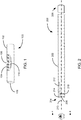
- FIG. 1 is a drawing of a flow diverter 100.
- the flow diverter 100 includes a self-expanding tubular mesh frame 102, which has high porosity. "High porosity" indicates that the mesh of the component includes more open space than vessel coverage. A high porosity component thus has a low metal-to-artery ratio. The metal-to-artery ratio is calculated by dividing the cylindrical area that the device covers in the artery by the total cylindrical area of the artery segment containing the device.
- the tubular mesh frame 102 has an expanded (free) state and a collapsed state. The expanded state is shown. The tubular mesh frame 102 must be externally compressed to enter the collapsed state and resumes the expanded state under the proper conditions.
- the tubular mesh frame 102 can automatically resume the expanded state by action of internal tension forces as soon as an external constraint is removed. In other examples, the tubular mesh frame 102 may resume the expanded state in response to a thermal input or an electrical signal.
- a tubular mesh frame 102 can be fabricated from shape-memory alloy such as nickel-titanium alloy (nitinol).
- a low porosity (high metal-to-artery ratio) mesh cover 104 is incorporated with the tubular mesh frame 102.
- the mesh cover 104 is placed over the mid-section of the tubular mesh frame 102.
- the mesh cover 104 generally may have a circular, rounded, or oblong shape 110.
- An opening 106 is formed in the center of the mesh cover 104.
- the opening 106 is sufficiently large to allow a guiding device, such as a steerable radiopaque guidewire (or microcatheter) to pass through it.
- the mesh cover 104 may be integrated as part of the tubular mesh frame 102. In one example, the mesh cover 104 may be woven from the same filaments as the tubular mesh frame 102, but in a tighter pattern. In other examples, the mesh cover 104 may be a separate element attached to the tubular mesh frame 102. In one such example the mesh cover 104 may attached to the tubular mesh frame 102 by welding. In another such example the mesh cover 104 may attached to the tubular mesh frame 102 by an adhesive. In another example, filaments of the mesh cover 104 may be interlaced with the filaments of the tubular mesh frame 102.
- the mesh cover 104 may attached to the tubular mesh frame 102 by temporarily and locally melting either the mesh cover 104 or tubular mesh frame to fuse the two together (as opposed to welding, which would temporarily melt both to create the bond).
- the mesh cover 104 may be attached to the tubular mesh frame 102 by sandwiching the mesh cover 104 between layers of the tubular mesh frame 104, or vice versa.
- FIG. 7 illustrates the flow diverter 100 in the collapsed state.
- a collapsed portion 700 is formed in the tubular mesh frame 102 and the mesh cover 104 to accommodate a distal end 302 of a delivery wire 300 while the flow diverter is advanced through a microcatheter 200 for placement over an aneurysm (see below for more detail on tools and techniques for delivering and placing the flow diverter 100).
- FIG. 8 illustrates a cross-section of the collapsed flow diverter 100 through the tubular mesh frame 102 only. The collapsed portion 100 can be seen more clearly in this cross-sectional view.
- FIG. 9 illustrates a cross-section of the collapsed flow diverter 100 through the center of the opening 106. As such, the relationship between the collapsed portion 700, the opening 106, the tubular mesh frame 102, and the mesh cover 104 can be seen.
- FIG. 2 illustrates a microcatheter 200 for delivering the flow diverter 100.
- the microcatheter 200 has a tubular outer wall 202, a distal end 204, a proximal end 206, and a longitudinal axis 210 which is approximately coincident with the center of the tubular outer wall 202 along its length.
- the distal end includes a transverse opening 208 and a longitudinal opening 212.
- the transverse opening 208 may be substantially perpendicular to the longitudinal axis 210.
- the transverse opening 208 may be at an angle to the longitudinal axis 210.
- the longitudinal opening 212 may be a slot or similar shape having a long dimension following the length of the microcatheter 200 and a short dimension on the circumference (or other non-circular perimeter) of the microcatheter 200.
- One end of the longitudinal opening 212 intersects 214 the transverse opening 208 at the distal end 204 of the microcatheter 200.
- the other end of the longitudinal opening may be square (i.e. having right-angle corners with or without radii), semicircular, or elliptical.
- the distal end 24 of the microcatheter 200 may also include a radiopaque marker 218.
- the radiopaque marker 218 allows a clinician to observe the location of the distal end 204 of the microcatheter 200 within a patient's vascular system using a radiological instrument.
- a clinician may use fluoroscopy, digital subtraction angiography, rotational angiography, computed tomography (CT), cone beam CT, or the like to observe the location of the radiopaque marker 218.
- CT computed tomography
- the radiopaque marker 218 may be a circular band or ring shape.
- the circular band may be a split ring shape, where the split in the ring is aligned with the longitudinal opening 212.
- FIG. 3 illustrates a steerable delivery wire 300 for delivering the flow diverter 100.
- the delivery wire 300 is deployed within the microcatheter 200.
- the delivery wire 300 includes a distal section 302, a proximal section 304, and a junction 306 between the distal section 302 and/or the proximal section 304. At least a portion of the distal section 302 of the delivery wire 300 is configured to adopt a curved configuration.
- the distal section 302 has a smaller cross section than the proximal section 304. In some examples, the distal section 302 can slide relative to the proximal section 304. This allows the tip of delivery wire to be retracted after the flow diverter is placed across the neck of the aneurysm.
- both the distal section 302 and the proximal section 304 have circular cross sections.
- the distal section 302 and the proximal section 304 may have non-circular cross-sections.
- either of the distal section 302 or the proximal section 304 may have elliptical, oblong, oval, triangular, or quadrilateral cross sections.
- the non-circular cross section of either the distal section 302 or the proximal section 304 may not have a consistent angular orientation along the length of the delivery wire 300.
- the distal section 302 includes a tip 310.
- the tip 310 may include a radiopaque marker 314.
- the portion of the distal section 302 of the delivery wire 300 configured to adopt a curved configuration is preset into the curved configuration and reverts to the curved configuration from a straightened configuration when deployed from the microcatheter.
- the section is in the curved configuration when the delivery wire is in its free state.
- the inner diameter of the microcather constrains the delivery wire and forces the curved portion into a straightened configuration.
- the section reverts to its preset curved configuration.
- the curved section may be formed from flexible resilient materials.
- the curved section may be formed from spring steel or may be heat-treated to form the curved section in its free state.
- At least one pull wire 308 is positioned within the lumen 316 of the delivery wire 300.
- the pull wire 308 or wires are attached to the tip 310 of the distal section 302 so that when a pull wire 308 is pulled from a proximal end 318 of the proximal section 304 of the deliver wire 300, it causes at least a portion of the distal section 302 near the tip 310 to curve. This allows a clinician to guide the tip 310 of the distal section 302 of the delivery wire 300 into an aneurysm.
- the entire distal section 302 may curve when the pull wire 308 is pulled.
- a portion of the proximal section 304 may also curve when the pull wire 308 is pulled.
- the junction 306 between the distal section 302 and the proximal section 304 has a cross section at least as large as the proximal section 304.
- the junction 306 is used to push the flow diverter 100 out of the microcatheter 200 for placement across the neck of an aneurysm, as will be explained in greater detail below.
- the junction 306 may also include a radiopaque marker 312.
- FIG. 4 is a cross-sectional view illustrating the microcatheter 200 with the delivery wire 300 and flow diverter 100 installed in preparation for placement in a blood vessel.
- the flow diverter 100 is mounted over distal section 302 of the guidewire 300 by guiding the opening 106 over the distal section 302 until the tubular mesh framework 102 meets the junction 306 between the distal section 302 and the proximal section 304 of the delivery wire 300.
- the tubular mesh framework 102 of the flow diverter 100 is then compressed into its collapsed state, pre-loaded into an introducer (not shown), and transferred into the microcatheter lumen 220.
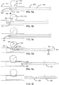
- FIGs. 5a-5f are a series of drawings illustrating one example of a sequence of steps for placing the flow diverter 100 in a blood vessel 514 to occlude an aneurysm 512.
- the microcatheter 200 is advanced across the neck 516 of the aneurysm 512.
- the radial alignment of the longitudinal opening 212 of the microcatheter 200 with the aneurysm is checked and adjusted, if necessary.
- the tip 310 of the distal section 302 of the delivery wire 300 is then advanced out of the microcatheter 200 and guided through the neck 516 of the aneurysm 512.
- the delivery wire may have a preset curvature, as described above, or may be guided using a pull wire 308.
- the delivery wire is engaged with the implant by passing through orifice 106, but is not attached.
- the flow diverter 100 may be deployed. The flow diverter 100 is deployed by pulling back on the microcatheter 200 while maintaining the position of the delivery wire 300.
- the self-expanding tubular frame 102 opens against the interior of the blood vessel 514 while the flow diverter 100 is guided along the distal section 302 of the delivery wire 300 by its opening 106.
- the flow diverter 100 is fully deployed from the microcatheter 200 and expanded.
- the delivery wire 300 is withdrawn back into the microcatheter 200 and they can both be withdrawn from the patient.
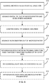
- FIG. 6 is a flow chart illustrating the sequence of steps for placing the flow diverter in a blood vessel to occlude an aneurysm.
- the clinician advances the microcatheter in the distal direction across a neck of an aneurysm in a blood vessel.
- the clinician advances the distal tip of the delivery wire out of the microcatheterand guides the distal tip of the delivery wire into the aneurysm.
- the clinician confirms, via a radiological imaging device, that the distal tip of the delivery wire is located inside the aneurysm.
- the radiological imaging device may include, for example, fluoroscopy, digital subtraction angiography, rotational angiography, computed tomography (CT), cone beam CT, or the like.
- the clinician deploys the flow diverter from the microcatheter.
- the clinician withdraws the microcatheter in the proximal direction while maintaining the position of the delivery wire so that the self-expanding frame of the vascular flow diverter opens against the inner wall of the blood vessel while the distal tip of the delivery wire guides a mesh cover of the vascular flow diverter across the neck of the aneurysm.
- the clinician withdraws the delivery wire into the microcatheter.
- the clinician withdraws the delivery wire and the microcatheter from the patient.
Landscapes
- Health & Medical Sciences (AREA)
- Engineering & Computer Science (AREA)
- Biomedical Technology (AREA)
- Life Sciences & Earth Sciences (AREA)
- Veterinary Medicine (AREA)
- General Health & Medical Sciences (AREA)
- Heart & Thoracic Surgery (AREA)
- Public Health (AREA)
- Animal Behavior & Ethology (AREA)
- Vascular Medicine (AREA)
- Oral & Maxillofacial Surgery (AREA)
- Cardiology (AREA)
- Transplantation (AREA)
- Pulmonology (AREA)
- Gastroenterology & Hepatology (AREA)
- Surgical Instruments (AREA)
- Biophysics (AREA)
- Hematology (AREA)
- Anesthesiology (AREA)
- Surgery (AREA)
- Prostheses (AREA)
- Molecular Biology (AREA)
- Medical Informatics (AREA)
- Nuclear Medicine, Radiotherapy & Molecular Imaging (AREA)
- Reproductive Health (AREA)
Abstract
Description
- The disclosure relates generally to intravascular medical devices. The disclosure relates more specifically to medical devices for treating vascular trauma and deformities.
- Current vascular flow diverters consist of low-porosity braids that are deployed across the neck of the aneurysm and cover not only the periphery of the vessel across the neck of the aneurysm, but also a segment of otherwise healthy vessel proximal and distal to the neck of the aneurysm. Thromboembolic complications commonly result from these types of devices. Patients with such devices are prescribed long-term medication to alleviate the risk for device thrombosis.
- The ideal intra-luminal flow diverter would treat the neck of the aneurysm only, thus minimizing the amount of metal in the lumen of the vessel and the potential for thromboembolic complications. However, positioning of a neck cover against the neck of the aneurysm in a three-dimensional space under fluoroscopy guidance is difficult with currently available imaging technologies.
- No intra-vascular devices are commercially available that minimize the amount of metal in the vessel by targeting only the neck of the aneurysm. There are commercially available devices that attempt to treat the neck of the aneurysm intra-saccular, such as various aneurysm emobolization sytems (e.g. embolic coils).
- The present disclosure describes various examples of an intra-vascular flow-diverting device designed to minimize the amount of metal in the vessel by targeting only the neck of an aneurysm, devices for deploying the intra-vascular flow-diverting device, and methods for guiding and deploying a flow diverting device to cover the neck of an aneurysm.
- In one example of the disclosure, a vascular flow diverter includes a tubular mesh framework which includes a mesh cover and an opening. The tubular mesh framework is collapsible and configured to expand from a collapsed shape to a tubular shape when the vascular flow diverter is deployed. The mesh cover conforms to the shape of the tubular mesh, is surrounded by the tubular mesh framework, and is less porous than the tubular mesh framework. The opening is located within the mesh cover.
- In one example, the tubular mesh framework has a circular cross section. In one example, the mesh cover has a rounded perimeter. In another example, the mesh cover has a circular perimeter. In some examples, the mesh cover is integrated with the tubular mesh framework. In other examples, the mesh cover is separate from and attached to the tubular mesh framework. In one example, the mesh cover is attached to the tubular mesh framework by welding. In another example, the mesh cover is attached to the tubular mesh framework by interlacing mesh strands of the mesh cover with mesh strands of the tubular mesh framework.
- In one example of the disclosure, a device for deploying a vascular flow diverter includes a hollow microcatheter which includes a tubular outer wall, a distal end, and a proximal end. In one example, the distal end of the microcatheter includes a transverse opening which is substantially perpendicular to a longitudinal axis of the microcatheter and also includes a longitudinal opening which is substantially parallel to the longitudinal axis. The longitudinal opening intersects the transverse opening. The device also includes a delivery wire which includes a distal section, a proximal section, and a junction between the distal section and the proximal section. At least a portion of the distal section of the delivery wire is configured to adopt a curved configuration. The distal section has a smaller cross section than the proximal section.
- In one example, the portion of the distal section of the delivery wire configured to adopt a curved configuration is pre-formed into the curved configuration and configured to revert to the curved configuration from a straightened configuration when the distal section of the delivery wire is deployed from the microcatheter
- In another example, the delivery wire includes a pull wire. The pull wire is positioned in a lumen of the delivery wire and terminates at a tip of the distal section. A proximal end of the pull wire may be pulled to apply tension to the pull wire, which draws at least a portion of the distal section of the delivery wire into a curved configuration.
- In one example, a radiopaque marker may be fixed to the junction between the distal section and the proximal section of the delivery wire. In another example, a radiopaque marker may be fixed to the tip of the distal section of the delivery wire. In another example, the distal tip of the distal section of the delivery wire may be a coil formed from radiopaque material. In another example, a radiopaque marker may be fixed to the distal end of the microcatheter. In one example, the radiopaque marker fixed to the distal end of the microcatheter may be located between the transverse opening and a proximal end of the longitudinal opening. In a further example, the radiopaque marker fixed to the distal end of the microcatheter includes a split ring shape. In another further example, the split of the split ring shape is located astride the longitudinal opening of the microcatheter.
- In one example of the disclosure, a method for deploying the vascular flow diverter includes advancing a microcatheter in a distal direction across a neck of an aneurysm in a blood vessel, advancing a distal tip of a delivery wire out of the microcatheter, rotating the microcatheter so that the curved delivery wire tip exits through the longitudinal slot in the microcatheter, which radially aligns the mesh cover to the aneurysm entrance, and guiding the distal tip of the delivery wire into the aneurysm. The method also includes withdrawing the microcatheter in a proximal direction while maintaining a position of the delivery wire so that the self-expanding frame of the vascular flow diverter opens against an inner wall of the blood vessel and the distal tip of the delivery wire guides the mesh cover of the vascular flow diverter across the neck of the aneurysm.
- In another example, the method also includes confirming, via a radiological imaging device, that the distal tip of the delivery wire is located inside the aneurysm. In another example, the method includes withdrawing the delivery wire into the microcatheter and withdrawing the delivery wire and the microcatheter from a patient.
-
- FIG. 1 is a drawing of a flow diverter illustrating its primary components and their relationship to each other, in accordance with the present disclosure.
- FIG. 2 is a drawing of a microcatheter for delivering the flow diverter, illustrating its primary components and their relationship to each other, in accordance with the present disclosure.
- FIG. 3 is a drawing of one example of a delivery wire for delivering the flow diverter, illustrating its primary components and their relationship to each other, in accordance with the present disclosure.
- FIG. 4 is a cross-sectional view of one example of the microcatheter with the delivery wire and flow diverter installed in preparation for placement in a blood vessel, in accordance with the present disclosure.
- FIGs. 5a-5f are a series of drawings of an aneurysm in a blood vessel, illustrating an example of a sequence of steps for placing the flow diverter in a blood vessel to occlude an aneurysm, in accordance with the present disclosure.
- FIG. 6 is a flow chart illustrating an example of a sequence of steps for placing the flow diverter in a blood vessel to occlude an aneurysm.
- FIG. 7 is a drawing of a flow diverter in the collapsed configuration, in accordance with the present disclosure
- FIG. 8 is a drawing of a cross-section of the collapsed flow diverter of FIG. 7, in accordance with the present disclosure
- FIG. 9 is a drawing of another cross-section of the collapsed flow diverter of FIG. 7, in accordance with the present disclosure
- Referring now to the Figures, in which like reference numerals represent like parts, various examples of the computing devices and methods will be disclosed in detail.
- FIG. 1 is a drawing of a
flow diverter 100. Theflow diverter 100 includes a self-expandingtubular mesh frame 102, which has high porosity. "High porosity" indicates that the mesh of the component includes more open space than vessel coverage. A high porosity component thus has a low metal-to-artery ratio. The metal-to-artery ratio is calculated by dividing the cylindrical area that the device covers in the artery by the total cylindrical area of the artery segment containing the device. Thetubular mesh frame 102 has an expanded (free) state and a collapsed state. The expanded state is shown. Thetubular mesh frame 102 must be externally compressed to enter the collapsed state and resumes the expanded state under the proper conditions. In some examples, thetubular mesh frame 102 can automatically resume the expanded state by action of internal tension forces as soon as an external constraint is removed. In other examples, thetubular mesh frame 102 may resume the expanded state in response to a thermal input or an electrical signal. On example of such atubular mesh frame 102 can be fabricated from shape-memory alloy such as nickel-titanium alloy (nitinol). - A low porosity (high metal-to-artery ratio)
mesh cover 104 is incorporated with thetubular mesh frame 102. Themesh cover 104 is placed over the mid-section of thetubular mesh frame 102. Themesh cover 104 generally may have a circular, rounded, oroblong shape 110. Anopening 106 is formed in the center of themesh cover 104. Theopening 106 is sufficiently large to allow a guiding device, such as a steerable radiopaque guidewire (or microcatheter) to pass through it. - In some examples, the
mesh cover 104 may be integrated as part of thetubular mesh frame 102. In one example, themesh cover 104 may be woven from the same filaments as thetubular mesh frame 102, but in a tighter pattern. In other examples, themesh cover 104 may be a separate element attached to thetubular mesh frame 102. In one such example themesh cover 104 may attached to thetubular mesh frame 102 by welding. In another such example themesh cover 104 may attached to thetubular mesh frame 102 by an adhesive. In another example, filaments of themesh cover 104 may be interlaced with the filaments of thetubular mesh frame 102. In another such example themesh cover 104 may attached to thetubular mesh frame 102 by temporarily and locally melting either themesh cover 104 or tubular mesh frame to fuse the two together (as opposed to welding, which would temporarily melt both to create the bond). In another such example themesh cover 104 may be attached to thetubular mesh frame 102 by sandwiching themesh cover 104 between layers of thetubular mesh frame 104, or vice versa. - FIG. 7 illustrates the
flow diverter 100 in the collapsed state. Acollapsed portion 700 is formed in thetubular mesh frame 102 and themesh cover 104 to accommodate adistal end 302 of adelivery wire 300 while the flow diverter is advanced through amicrocatheter 200 for placement over an aneurysm (see below for more detail on tools and techniques for delivering and placing the flow diverter 100). FIG. 8 illustrates a cross-section of thecollapsed flow diverter 100 through thetubular mesh frame 102 only. Thecollapsed portion 100 can be seen more clearly in this cross-sectional view. FIG. 9 illustrates a cross-section of thecollapsed flow diverter 100 through the center of theopening 106. As such, the relationship between thecollapsed portion 700, theopening 106, thetubular mesh frame 102, and themesh cover 104 can be seen. - FIG. 2 illustrates a
microcatheter 200 for delivering theflow diverter 100. Themicrocatheter 200 has a tubularouter wall 202, adistal end 204, aproximal end 206, and alongitudinal axis 210 which is approximately coincident with the center of the tubularouter wall 202 along its length. The distal end includes atransverse opening 208 and alongitudinal opening 212. In some examples, thetransverse opening 208 may be substantially perpendicular to thelongitudinal axis 210. In some examples, thetransverse opening 208 may be at an angle to thelongitudinal axis 210. - The
longitudinal opening 212 may be a slot or similar shape having a long dimension following the length of themicrocatheter 200 and a short dimension on the circumference (or other non-circular perimeter) of themicrocatheter 200. One end of thelongitudinal opening 212 intersects 214 thetransverse opening 208 at thedistal end 204 of themicrocatheter 200. The other end of the longitudinal opening may be square (i.e. having right-angle corners with or without radii), semicircular, or elliptical. - The distal end 24 of the
microcatheter 200 may also include aradiopaque marker 218. Theradiopaque marker 218 allows a clinician to observe the location of thedistal end 204 of themicrocatheter 200 within a patient's vascular system using a radiological instrument. For example, a clinician may use fluoroscopy, digital subtraction angiography, rotational angiography, computed tomography (CT), cone beam CT, or the like to observe the location of theradiopaque marker 218. In some examples, theradiopaque marker 218 may be a circular band or ring shape. In some further examples, the circular band may be a split ring shape, where the split in the ring is aligned with thelongitudinal opening 212. - FIG. 3 illustrates a
steerable delivery wire 300 for delivering theflow diverter 100. Thedelivery wire 300 is deployed within themicrocatheter 200. Thedelivery wire 300 includes adistal section 302, aproximal section 304, and ajunction 306 between thedistal section 302 and/or theproximal section 304. At least a portion of thedistal section 302 of thedelivery wire 300 is configured to adopt a curved configuration. Thedistal section 302 has a smaller cross section than theproximal section 304. In some examples, thedistal section 302 can slide relative to theproximal section 304. This allows the tip of delivery wire to be retracted after the flow diverter is placed across the neck of the aneurysm. In some examples, both thedistal section 302 and theproximal section 304 have circular cross sections. In other examples, thedistal section 302 and theproximal section 304 may have non-circular cross-sections. For instance either of thedistal section 302 or theproximal section 304 may have elliptical, oblong, oval, triangular, or quadrilateral cross sections. In addition, in some examples the non-circular cross section of either thedistal section 302 or theproximal section 304 may not have a consistent angular orientation along the length of thedelivery wire 300. Thedistal section 302 includes atip 310. In some examples, thetip 310 may include aradiopaque marker 314. - In one example, the portion of the
distal section 302 of thedelivery wire 300 configured to adopt a curved configuration is preset into the curved configuration and reverts to the curved configuration from a straightened configuration when deployed from the microcatheter. Thus, the section is in the curved configuration when the delivery wire is in its free state. When the delivery wire is inserted into the microcatheter the inner diameter of the microcather constrains the delivery wire and forces the curved portion into a straightened configuration. When the delivery wire is deployed from the microcatheter the section reverts to its preset curved configuration. The curved section may be formed from flexible resilient materials. For example, the curved section may be formed from spring steel or may be heat-treated to form the curved section in its free state. - In another example, at least one
pull wire 308 is positioned within thelumen 316 of thedelivery wire 300. Thepull wire 308 or wires are attached to thetip 310 of thedistal section 302 so that when apull wire 308 is pulled from aproximal end 318 of theproximal section 304 of the deliverwire 300, it causes at least a portion of thedistal section 302 near thetip 310 to curve. This allows a clinician to guide thetip 310 of thedistal section 302 of thedelivery wire 300 into an aneurysm. In some examples, the entiredistal section 302 may curve when thepull wire 308 is pulled. In other examples, a portion of theproximal section 304 may also curve when thepull wire 308 is pulled. - The
junction 306 between thedistal section 302 and theproximal section 304 has a cross section at least as large as theproximal section 304. Thejunction 306 is used to push theflow diverter 100 out of themicrocatheter 200 for placement across the neck of an aneurysm, as will be explained in greater detail below. In some examples, thejunction 306 may also include aradiopaque marker 312. - FIG. 4 is a cross-sectional view illustrating the
microcatheter 200 with thedelivery wire 300 and flowdiverter 100 installed in preparation for placement in a blood vessel. Theflow diverter 100 is mounted overdistal section 302 of theguidewire 300 by guiding theopening 106 over thedistal section 302 until thetubular mesh framework 102 meets thejunction 306 between thedistal section 302 and theproximal section 304 of thedelivery wire 300. Thetubular mesh framework 102 of theflow diverter 100 is then compressed into its collapsed state, pre-loaded into an introducer (not shown), and transferred into themicrocatheter lumen 220. - FIGs. 5a-5f are a series of drawings illustrating one example of a sequence of steps for placing the
flow diverter 100 in ablood vessel 514 to occlude ananeurysm 512. At FIG. 5a themicrocatheter 200 is advanced across theneck 516 of theaneurysm 512. At FIG. 5b, the radial alignment of thelongitudinal opening 212 of themicrocatheter 200 with the aneurysm is checked and adjusted, if necessary. Thetip 310 of thedistal section 302 of thedelivery wire 300 is then advanced out of themicrocatheter 200 and guided through theneck 516 of theaneurysm 512. The delivery wire may have a preset curvature, as described above, or may be guided using apull wire 308. The delivery wire is engaged with the implant by passing throughorifice 106, but is not attached. At FIG. 5c, after confirming that thetip 310 of thedistal section 302 is seated in theaneurysm 512, theflow diverter 100 may be deployed. Theflow diverter 100 is deployed by pulling back on themicrocatheter 200 while maintaining the position of thedelivery wire 300. - At FIG. 5d, the self-expanding
tubular frame 102 opens against the interior of theblood vessel 514 while theflow diverter 100 is guided along thedistal section 302 of thedelivery wire 300 by itsopening 106. At FIG. 5e, theflow diverter 100 is fully deployed from themicrocatheter 200 and expanded. At FIG. 5f, thedelivery wire 300 is withdrawn back into themicrocatheter 200 and they can both be withdrawn from the patient. - FIG. 6 is a flow chart illustrating the sequence of steps for placing the flow diverter in a blood vessel to occlude an aneurysm. At 600, the clinician advances the microcatheter in the distal direction across a neck of an aneurysm in a blood vessel. At 602, the clinician advances the distal tip of the delivery wire out of the microcatheterand guides the distal tip of the delivery wire into the aneurysm. At 604, the clinician confirms, via a radiological imaging device, that the distal tip of the delivery wire is located inside the aneurysm. The radiological imaging device may include, for example, fluoroscopy, digital subtraction angiography, rotational angiography, computed tomography (CT), cone beam CT, or the like. At 606, the clinician deploys the flow diverter from the microcatheter. At 608, the clinician withdraws the microcatheter in the proximal direction while maintaining the position of the delivery wire so that the self-expanding frame of the vascular flow diverter opens against the inner wall of the blood vessel while the distal tip of the delivery wire guides a mesh cover of the vascular flow diverter across the neck of the aneurysm. At 610, the clinician withdraws the delivery wire into the microcatheter. At 612, the clinician withdraws the delivery wire and the microcatheter from the patient.
- To facilitate an understanding of the principals and features of the disclosed technology, illustrative examples are explained above. The components described as making up various elements of the disclosed technology are intended to be illustrative and not restrictive. Many suitable components that would perform the same or similar functions as components described herein are intended to be embraced within the scope of the disclosed electronic devices and methods. Such other components not described herein may include, but are not limited to, for example, components developed after development of the disclosed technology.
- It must also be noted that, as used in the specification and the appended claims, the singular forms "a," "an" and "the" include plural referents unless the context clearly dictates otherwise.
- By "comprising" or "containing" or "including" is meant that at least the named component, element, or method step is present in the article or method, but does not exclude the presence of other component, materials, elements, method steps, even if the other such component, materials, elements, method steps have the same function as what is named.
- It is also to be understood that the mention of one or more method steps does not preclude the presence of additional method steps or intervening method steps between those steps expressly identified. Similarly, it is also to be understood that the mention of one or more components in a device or system does not preclude the presence of additional components or intervening components between those components expressly identified.
- The design and functionality described in this application is intended to be exemplary in nature and is not intended to limit the instant disclosure in any way. Those having ordinary skill in the art will appreciate that the teachings of the disclosure may be implemented in a variety of suitable forms, including those forms disclosed herein and additional forms known to those having ordinary skill in the art.
- While certain examples of this disclosure have been described in connection with what is presently considered to be the most practical and various examples, it is to be understood that this disclosure is not to be limited to the disclosed examples, but on the contrary, is intended to cover various modifications and equivalent arrangements included within the scope of the appended claims. Although specific terms are employed herein, they are used in a generic and descriptive sense only and not for purposes of limitation.
- This written description uses examples to disclose certain examples of the technology and also to enable any person skilled in the art to practice certain examples of this technology, including making and using any apparatuses or systems and performing any incorporated methods. The patentable scope of certain examples of the technology is defined in the claims, and may include other examples that occur to those skilled in the art. Such other examples are intended to be within the scope of the claims if they have structural elements that do not differ from the literal language of the claims, or if they include equivalent structural elements with insubstantial differences from the literal language of the claims.
Claims (20)
- A vascular flow diverter comprising:
a tubular mesh framework comprising a mesh cover and an opening, where:the tubular mesh framework is collapsible and configured to expand from a collapsed shape to a tubular shape when the vascular flow diverter is deployed;the mesh cover conforms to the shape of the tubular mesh and is surrounded by the tubular mesh framework;the opening is located within the mesh cover; andthe tubular mesh framework is more porous than the mesh cover. - The vascular flow diverter of claim 1 where the tubular mesh framework has a circular cross section.
- The vascular flow diverter of claim 1 where the mesh cover has a rounded perimeter.
- The vascular flow diverter of claim 1 where the mesh cover has a circular perimeter
- The vascular flow diverter of claim 1 where the mesh cover is integrated with the tubular mesh framework.
- The vascular flow diverter of claim 1 where the mesh cover is separate from and attached to the tubular mesh framework.
- The vascular flow diverter of claim 6 where the mesh cover is attached to the tubular mesh framework by welding.
- The vascular flow diverter of claim 1 where the mesh cover is attached to the tubular mesh framework by interlacing mesh strands of the mesh cover with mesh strands of the tubular mesh framework.
- A device for deploying a vascular flow diverter, the device comprising:a microcatheter comprising a tubular outer wall, a distal end, and a proximal end, the distal end comprising a transverse opening and a longitudinal opening, where the longitudinal opening intersects the transverse opening; anda delivery wire comprising a distal section, a proximal section, and a junction between the distal section and the proximal section, where:the distal section has a smaller cross section than the proximal section; andwhere the distal section is steerable from a proximate end of the proximate section, where at least a portion of the distal section of the delivery wire is configured to adopt a curved configuration.
- The device for deploying a vascular flow diverter of claim 9, where the transverse opening is substantially perpendicular to a longitudinal axis of the microcatheter and the longitudinal opening is substantially parallel to the longitudinal axis of the microcatheter.
- The device for deploying a vascular flow diverter of claim 9, where the portion of the distal section of the delivery wire configured to adopt a curved configuration is pre-formed into the curved configuration and configured to revert to the curved configuration from a straightened configuration when the distal section of the delivery wire is deployed from the microcatheter.
- The device for deploying a vascular flow diverter of claim 9, further comprising a pull wire positioned in a lumen of the delivery wire and terminating at a tip of the distal section;
where a proximal end of the pull wire may be pulled to form the curved configuration in at least a portion of the distal section. - The device for deploying a vascular flow diverter of claim 9, further comprising a radiopaque marker fixed to the junction between the distal section and the proximal section.
- The device for deploying a vascular flow diverter of claim 9, further comprising a radiopaque marker fixed to a tip of the distal section.
- The device for deploying a vascular flow diverter of claim 9, further comprising a radiopaque marker fixed to the distal end of the microcatheter.
- The device for deploying a vascular flow diverter of claim 15, where the radiopaque marker fixed to the distal end of the microcatheter is located between the transverse opening and a proximal end of the longitudinal opening.
- The device for deploying a vascular flow diverter of claim 16, where the radiopaque marker fixed to the distal end of the microcatheter comprises a split ring shape.
- The device for deploying a vascular flow diverter of claim 9 where the curved portion of the distal section of the of the delivery wire passes through an opening formed in a tubular mesh vascular flow diverter in order to guide the tubular mesh vascular flow diverter into position over a neck of an aneurysm during deployment of the tubular mesh vascular flow diverter.
- A method for deploying a vascular flow diverter, the method comprising:advancing a microcatheter in a distal direction across a neck of an aneurysm in a blood vessel;advancing a distal tip of a delivery wire out of the microcatheter;guiding the distal tip of the delivery wire into the aneurysm;withdrawing the microcatheter in a proximal direction while maintaining a position of the delivery wire such that a self-expanding frame of the vascular flow diverter opens against an inner wall of the blood vessel while the distal tip of the delivery wire guides a mesh cover of the vascular flow diverter across the neck of the aneurysm.
- The method of claim 18, further comprising:
confirming, via a radiological imaging device that the distal tip of the delivery wire is located inside the aneurysm.
Applications Claiming Priority (1)
| Application Number | Priority Date | Filing Date | Title |
|---|---|---|---|
| US15/416,324 US10881497B2 (en) | 2017-01-26 | 2017-01-26 | Composite vascular flow diverter |
Publications (3)
| Publication Number | Publication Date |
|---|---|
| EP3354236A2 true EP3354236A2 (en) | 2018-08-01 |
| EP3354236A3 EP3354236A3 (en) | 2018-10-17 |
| EP3354236B1 EP3354236B1 (en) | 2022-11-02 |
Family
ID=61027530
Family Applications (1)
| Application Number | Title | Priority Date | Filing Date |
|---|---|---|---|
| EP18153379.5A Active EP3354236B1 (en) | 2017-01-26 | 2018-01-25 | Composite vascular flow diverter |
Country Status (7)
| Country | Link |
|---|---|
| US (2) | US10881497B2 (en) |
| EP (1) | EP3354236B1 (en) |
| JP (2) | JP7150440B2 (en) |
| KR (1) | KR102582799B1 (en) |
| CN (2) | CN108354699B (en) |
| BR (1) | BR102018001664A2 (en) |
| ES (1) | ES2933494T3 (en) |
Families Citing this family (2)
| Publication number | Priority date | Publication date | Assignee | Title |
|---|---|---|---|---|
| US11957356B2 (en) | 2022-02-24 | 2024-04-16 | NV MEDTECH, Inc. | Methods and apparatus for stent assisted aneurysm coiling |
| AU2023268774A1 (en) * | 2022-05-13 | 2025-01-02 | Gilad Cibulski | Bendable guidewire lumen |
Family Cites Families (165)
| Publication number | Priority date | Publication date | Assignee | Title |
|---|---|---|---|---|
| US4719924A (en) * | 1986-09-09 | 1988-01-19 | C. R. Bard, Inc. | Small diameter steerable guidewire with adjustable tip |
| US5396902A (en) * | 1993-02-03 | 1995-03-14 | Medtronic, Inc. | Steerable stylet and manipulative handle assembly |
| US5980554A (en) | 1997-05-05 | 1999-11-09 | Micro Therapeutics, Inc. | Wire frame partial flow obstruction for aneurysm treatment |
| US5951599A (en) | 1997-07-09 | 1999-09-14 | Scimed Life Systems, Inc. | Occlusion system for endovascular treatment of an aneurysm |
| US5911725A (en) * | 1997-08-22 | 1999-06-15 | Boury; Harb N. | Intraluminal retrieval catheter |
| US6093199A (en) * | 1998-08-05 | 2000-07-25 | Endovascular Technologies, Inc. | Intra-luminal device for treatment of body cavities and lumens and method of use |
| US6409683B1 (en) * | 1998-09-30 | 2002-06-25 | Cordis Corporation | Medical guidewire with improved coil attachment |
| US6613074B1 (en) | 1999-03-10 | 2003-09-02 | Cordis Corporation | Endovascular aneurysm embolization device |
| US6391037B1 (en) | 2000-03-02 | 2002-05-21 | Prodesco, Inc. | Bag for use in the intravascular treatment of saccular aneurysms |
| US8252040B2 (en) | 2001-07-20 | 2012-08-28 | Microvention, Inc. | Aneurysm treatment device and method of use |
| US8715312B2 (en) | 2001-07-20 | 2014-05-06 | Microvention, Inc. | Aneurysm treatment device and method of use |
| US20030139802A1 (en) * | 2001-12-06 | 2003-07-24 | Wulfman Edward I. | Medical device |
| US20040068314A1 (en) * | 2002-01-16 | 2004-04-08 | Jones Donald K. | Detachable self -expanding aneurysm cover device |
| US6939368B2 (en) * | 2002-01-17 | 2005-09-06 | Scimed Life Systems, Inc. | Delivery system for self expanding stents for use in bifurcated vessels |
| US7371228B2 (en) | 2003-09-19 | 2008-05-13 | Medtronic Vascular, Inc. | Delivery of therapeutics to treat aneurysms |
| US8182544B2 (en) | 2003-10-08 | 2012-05-22 | Codman & Shurtleff, Inc. | Method for placing a medical agent into a vessel of the body |
| US7763011B2 (en) * | 2003-12-22 | 2010-07-27 | Boston Scientific Scimed, Inc. | Variable density braid stent |
| US20050197687A1 (en) * | 2004-03-02 | 2005-09-08 | Masoud Molaei | Medical devices including metallic films and methods for making same |
| US9308382B2 (en) | 2004-06-10 | 2016-04-12 | Medtronic Urinary Solutions, Inc. | Implantable pulse generator systems and methods for providing functional and/or therapeutic stimulation of muscles and/or nerves and/or central nervous system tissue |
| US9655633B2 (en) | 2004-09-10 | 2017-05-23 | Penumbra, Inc. | System and method for treating ischemic stroke |
| EP1804719A2 (en) | 2004-09-22 | 2007-07-11 | Lee R. Guterman | Cranial aneurysm treatment arrangement |
| US8968390B2 (en) * | 2004-09-27 | 2015-03-03 | Medinol Ltd. | Covering for an endoprosthetic device and methods of using for aneurysm treatment |
| US20060089637A1 (en) | 2004-10-14 | 2006-04-27 | Werneth Randell L | Ablation catheter |
| US7156871B2 (en) | 2004-10-28 | 2007-01-02 | Cordis Neurovascular, Inc. | Expandable stent having a stabilized portion |
| US8562672B2 (en) | 2004-11-19 | 2013-10-22 | Medtronic, Inc. | Apparatus for treatment of cardiac valves and method of its manufacture |
| US7922754B2 (en) | 2005-04-18 | 2011-04-12 | Trireme Medical, Inc. | Apparatus and methods for delivering prostheses to luminal bifurcations |
| US9636115B2 (en) | 2005-06-14 | 2017-05-02 | Stryker Corporation | Vaso-occlusive delivery device with kink resistant, flexible distal end |
| EP1895927A4 (en) | 2005-06-20 | 2011-03-09 | Medtronic Ablation Frontiers | Ablation catheter |
| US8066036B2 (en) | 2005-11-17 | 2011-11-29 | Microvention, Inc. | Three-dimensional complex coil |
| WO2007088549A2 (en) | 2006-02-03 | 2007-08-09 | Design & Performance - Cyprus Limited | Implantable graft assembly and aneurysm treatment |
| US9757260B2 (en) | 2006-03-30 | 2017-09-12 | Medtronic Vascular, Inc. | Prosthesis with guide lumen |
| US9615832B2 (en) | 2006-04-07 | 2017-04-11 | Penumbra, Inc. | Aneurysm occlusion system and method |
| US8777979B2 (en) * | 2006-04-17 | 2014-07-15 | Covidien Lp | System and method for mechanically positioning intravascular implants |
| US8377091B2 (en) | 2006-06-15 | 2013-02-19 | Microvention, Inc. | Embolization device constructed from expansile polymer |
| CA2659109A1 (en) * | 2006-08-09 | 2008-03-27 | Coherex Medical, Inc. | Devices for reducing the size of an internal tissue opening |
| WO2008063455A1 (en) | 2006-11-13 | 2008-05-29 | Hines Richard A | Over-the wire exclusion device and system for delivery |
| US20080281350A1 (en) | 2006-12-13 | 2008-11-13 | Biomerix Corporation | Aneurysm Occlusion Devices |
| US20110022149A1 (en) | 2007-06-04 | 2011-01-27 | Cox Brian J | Methods and devices for treatment of vascular defects |
| US20110160833A1 (en) | 2007-07-11 | 2011-06-30 | Carlos Gonzalez | Implantable graft assembly |
| WO2009019664A2 (en) * | 2007-08-07 | 2009-02-12 | Itgi Medical Ltd. | Method and devices useful for the treatment of aneurysms |
| CN101903051B (en) | 2007-12-21 | 2013-07-31 | 微温森公司 | Hydrogel filaments for biomedical applications |
| JP2011512206A (en) | 2008-02-20 | 2011-04-21 | マレー ヴァスキュラー ピィーティーワイ リミテッド | Stent |
| US8974518B2 (en) | 2008-03-25 | 2015-03-10 | Medtronic Vascular, Inc. | Eversible branch stent-graft and deployment method |
| US20090318948A1 (en) | 2008-04-22 | 2009-12-24 | Coherex Medical, Inc. | Device, system and method for aneurysm embolization |
| EP2197539A1 (en) | 2008-04-30 | 2010-06-23 | Medtronic, Inc. | Techniques for placing medical leads for electrical stimulation of nerve tissue |
| US8070694B2 (en) | 2008-07-14 | 2011-12-06 | Medtronic Vascular, Inc. | Fiber based medical devices and aspiration catheters |
| US8333796B2 (en) | 2008-07-15 | 2012-12-18 | Penumbra, Inc. | Embolic coil implant system and implantation method |
| US9232992B2 (en) | 2008-07-24 | 2016-01-12 | Aga Medical Corporation | Multi-layered medical device for treating a target site and associated method |
| US8721714B2 (en) | 2008-09-17 | 2014-05-13 | Medtronic Corevalve Llc | Delivery system for deployment of medical devices |
| US20100131002A1 (en) | 2008-11-24 | 2010-05-27 | Connor Robert A | Stent with a net layer to embolize and aneurysm |
| EP2416734A1 (en) * | 2009-04-02 | 2012-02-15 | The Medical Research, Infrastructure, And Health Services Fund Of The Tel Aviv Medical Center | Stent graft fenestration |
| EP2419166B1 (en) | 2009-04-15 | 2017-11-22 | MicroVention, Inc. | Implant delivery system |
| US8758423B2 (en) | 2009-06-18 | 2014-06-24 | Graftcraft I Goteborg Ab | Device and method for treating ruptured aneurysms |
| KR20120085238A (en) * | 2009-07-09 | 2012-07-31 | 머레이 배스큘라 피티와이 리미티드 | A support device for a tubular structure |
| US8911487B2 (en) | 2009-09-22 | 2014-12-16 | Penumbra, Inc. | Manual actuation system for deployment of implant |
| JP5775527B2 (en) * | 2009-12-01 | 2015-09-09 | アルツラ メディカル インコーポレイテッド | Modular endograft device and related systems and methods |
| US9561125B2 (en) | 2010-04-14 | 2017-02-07 | Microvention, Inc. | Implant delivery device |
| US8764811B2 (en) | 2010-04-20 | 2014-07-01 | Medtronic Vascular, Inc. | Controlled tip release stent graft delivery system and method |
| WO2011150118A2 (en) | 2010-05-25 | 2011-12-01 | The Regents Of The University Of California | Ultra-low fractional area coverage flow diverter for treating aneurysms and vascular diseases |
| US8876878B2 (en) | 2010-07-23 | 2014-11-04 | Medtronic, Inc. | Attachment mechanism for stent release |
| US8616040B2 (en) | 2010-09-17 | 2013-12-31 | Medtronic Vascular, Inc. | Method of forming a drug-eluting medical device |
| CA2822429A1 (en) | 2010-12-20 | 2012-06-28 | Microvention, Inc. | Polymer stents and methods of manufacture |
| CA2826760A1 (en) * | 2011-02-08 | 2012-08-16 | Advanced Bifurcation Systems, Inc. | Multi-stent and multi-balloon apparatus for treating bifurcations and methods of use |
| US20120226343A1 (en) | 2011-03-04 | 2012-09-06 | Stryker Nv Operations Limited | Stent delivery system |
| JP5641985B2 (en) | 2011-03-11 | 2014-12-17 | 株式会社カネカ | Medical tools |
| US20120283768A1 (en) | 2011-05-05 | 2012-11-08 | Sequent Medical Inc. | Method and apparatus for the treatment of large and giant vascular defects |
| US9486604B2 (en) | 2011-05-12 | 2016-11-08 | Medtronic, Inc. | Packaging and preparation tray for a delivery system |
| WO2012158668A1 (en) | 2011-05-17 | 2012-11-22 | Stryker Corporation | Method of fabricating an implantable medical device that includes one or more thin film polymer support layers |
| WO2012166467A1 (en) | 2011-05-27 | 2012-12-06 | Stryker Corporation | Assembly for percutaneously inserting an implantable medical device, steering the device to a target location and deploying the device |
| US20130085439A1 (en) * | 2011-09-30 | 2013-04-04 | Tyco Healthcare Group Lp | Device to encourage blood circulation between dialysis |
| US9750565B2 (en) | 2011-09-30 | 2017-09-05 | Medtronic Advanced Energy Llc | Electrosurgical balloons |
| KR101968885B1 (en) | 2012-03-16 | 2019-04-15 | 테루모 코퍼레이션 | Stent and stent delivery device |
| US9717421B2 (en) | 2012-03-26 | 2017-08-01 | Medtronic, Inc. | Implantable medical device delivery catheter with tether |
| US9833625B2 (en) | 2012-03-26 | 2017-12-05 | Medtronic, Inc. | Implantable medical device delivery with inner and outer sheaths |
| US9242290B2 (en) | 2012-04-03 | 2016-01-26 | Medtronic Vascular, Inc. | Method and apparatus for creating formed elements used to make wound stents |
| US9700399B2 (en) | 2012-04-26 | 2017-07-11 | Medtronic Vascular, Inc. | Stopper to prevent graft material slippage in a closed web stent-graft |
| US9549832B2 (en) | 2012-04-26 | 2017-01-24 | Medtronic Vascular, Inc. | Apparatus and methods for filling a drug eluting medical device via capillary action |
| US9888994B2 (en) * | 2012-05-15 | 2018-02-13 | Transverse Medical, Inc. | Catheter-based apparatuses and methods |
| EP2854704B1 (en) * | 2012-06-04 | 2016-12-21 | Penumbra, Inc. | Aneurysm occlusion system |
| US9149190B2 (en) | 2012-07-17 | 2015-10-06 | Stryker Corporation | Notification system of deviation from predefined conditions |
| WO2014028528A1 (en) | 2012-08-13 | 2014-02-20 | Microvention, Inc. | Shaped removal device |
| WO2014028913A1 (en) * | 2012-08-17 | 2014-02-20 | The Regents Of The University Of California | Dual rotational stent apparatus and method for endovascular treatment of aneurysms |
| US9504476B2 (en) | 2012-10-01 | 2016-11-29 | Microvention, Inc. | Catheter markers |
| BR112015008245B1 (en) | 2012-10-15 | 2022-09-27 | Microvention, Inc | POLYMERIC TREATMENT COMPOSITIONS |
| US9452070B2 (en) * | 2012-10-31 | 2016-09-27 | Covidien Lp | Methods and systems for increasing a density of a region of a vascular device |
| CN108354645B (en) | 2012-11-13 | 2026-03-13 | 柯惠有限合伙公司 | Sealing device |
| US9539022B2 (en) | 2012-11-28 | 2017-01-10 | Microvention, Inc. | Matter conveyance system |
| WO2014089405A1 (en) | 2012-12-07 | 2014-06-12 | Medtronic, Inc. | Minimally invasive implantable neurostimulation system |
| US20140180387A1 (en) | 2012-12-21 | 2014-06-26 | Stryker Nv Operations Limited | Stent delivery system |
| US10342546B2 (en) | 2013-01-14 | 2019-07-09 | Microvention, Inc. | Occlusive device |
| US9668892B2 (en) * | 2013-03-11 | 2017-06-06 | Endospan Ltd. | Multi-component stent-graft system for aortic dissections |
| US9539382B2 (en) | 2013-03-12 | 2017-01-10 | Medtronic, Inc. | Stepped catheters with flow restrictors and infusion systems using the same |
| CN105228534B (en) | 2013-03-14 | 2018-03-30 | 斯瑞克公司 | Vaso-Occlusive Device Delivery System |
| EP2967572B1 (en) | 2013-03-14 | 2019-04-24 | Stryker Corporation | Vaso-occlusive device delivery system |
| ES2879634T3 (en) | 2013-03-14 | 2021-11-22 | Stryker Corp | Vasoocclusive device delivery system |
| BR112015023602A2 (en) | 2013-03-15 | 2017-07-18 | Microvention Inc | embolic protection device |
| US9398966B2 (en) | 2013-03-15 | 2016-07-26 | Medtronic Vascular, Inc. | Welded stent and stent delivery system |
| US9545301B2 (en) * | 2013-03-15 | 2017-01-17 | Covidien Lp | Coated medical devices and methods of making and using same |
| WO2014151123A1 (en) | 2013-03-15 | 2014-09-25 | Microvention, Inc. | Multi-component obstruction removal system and method |
| ES2717678T3 (en) | 2013-04-22 | 2019-06-24 | Stryker European Holdings I Llc | Procedure for loading drugs onto implant surfaces coated with hydroxyapatite |
| US9445928B2 (en) | 2013-05-30 | 2016-09-20 | Medtronic Vascular, Inc. | Delivery system having a single handed deployment handle for a retractable outer sheath |
| US10265207B2 (en) * | 2013-08-27 | 2019-04-23 | Covidien Lp | Delivery of medical devices |
| US9675782B2 (en) | 2013-10-10 | 2017-06-13 | Medtronic Vascular, Inc. | Catheter pull wire actuation mechanism |
| US9955978B2 (en) | 2013-10-25 | 2018-05-01 | Medtronic Vascular, Inc. | Tissue compression device with multi-chamber bladder |
| GB2520482B (en) * | 2013-11-15 | 2015-12-23 | Cook Medical Technologies Llc | Aneurysm closure device |
| CA2934555C (en) | 2013-12-20 | 2020-07-07 | Microvention, Inc. | Device delivery system |
| CN106029157B (en) | 2013-12-20 | 2019-09-17 | 微仙美国有限公司 | Delivery adapter, fitting method of syringe and catheter and embolic agent delivery system |
| EP3116439B1 (en) * | 2014-03-10 | 2018-02-07 | TriVascular, Inc. | Inflatable occlusion wire-balloon for aortic applications |
| ES2684405T3 (en) | 2014-04-08 | 2018-10-02 | Stryker Corporation | Implant delivery system |
| US9662232B2 (en) * | 2014-04-11 | 2017-05-30 | Red Vascular Technologies, LLC | Alignment system for multiple branch endografts |
| US10226368B2 (en) * | 2014-04-23 | 2019-03-12 | Medtronic Vascular, Inc. | Delivery system for a retractable outer sheath |
| WO2015167997A1 (en) | 2014-04-30 | 2015-11-05 | Stryker Corporation | Implant delivery system and method of use |
| EP3145423B1 (en) * | 2014-05-20 | 2020-12-30 | Muffin Incorporated | Aneurysm stop pressure system |
| US9060777B1 (en) | 2014-05-28 | 2015-06-23 | Tw Medical Technologies, Llc | Vaso-occlusive devices and methods of use |
| US9668898B2 (en) | 2014-07-24 | 2017-06-06 | Medtronic Vascular, Inc. | Stent delivery system having dynamic deployment and methods of manufacturing same |
| US9770577B2 (en) | 2014-09-15 | 2017-09-26 | Medtronic Xomed, Inc. | Pressure relief for a catheter balloon device |
| US9579484B2 (en) | 2014-09-19 | 2017-02-28 | Medtronic Vascular, Inc. | Sterile molded dispenser |
| CN205729570U (en) * | 2014-12-31 | 2016-11-30 | 科迪斯公司 | Ink vessel transfusing implant and implant is deployed in the delivery apparatus in health tremulous pulse |
| US9692557B2 (en) | 2015-02-04 | 2017-06-27 | Stryker European Holdings I, Llc | Apparatus and methods for administering treatment within a bodily duct of a patient |
| US10314699B2 (en) | 2015-03-13 | 2019-06-11 | St. Jude Medical, Cardiology Division, Inc. | Recapturable valve-graft combination and related methods |
| US10111670B2 (en) * | 2015-05-01 | 2018-10-30 | DePuy Synthes Products, Inc. | Expandable vascular occlusion device with lead framing coil |
| US10154905B2 (en) | 2015-08-07 | 2018-12-18 | Medtronic Vascular, Inc. | System and method for deflecting a delivery catheter |
| US10307168B2 (en) | 2015-08-07 | 2019-06-04 | Terumo Corporation | Complex coil and manufacturing techniques |
| EP3334354B1 (en) | 2015-08-11 | 2021-03-03 | Terumo Corporation | System for implant delivery |
| WO2017049195A1 (en) | 2015-09-18 | 2017-03-23 | Microvention, Inc. | Implant retention, detachment, and delivery system |
| US10322020B2 (en) | 2015-09-18 | 2019-06-18 | Terumo Corporation | Pushable implant delivery system |
| EP3349670B1 (en) | 2015-09-18 | 2020-09-09 | Microvention, Inc. | Releasable delivery system |
| WO2017049212A1 (en) | 2015-09-18 | 2017-03-23 | Microvention, Inc. | Vessel prosthesis |
| US10292804B2 (en) | 2015-09-21 | 2019-05-21 | Stryker Corporation | Embolectomy devices |
| JP6592592B2 (en) | 2015-09-21 | 2019-10-16 | ストライカー コーポレイションStryker Corporation | Embolization device |
| US10172632B2 (en) | 2015-09-22 | 2019-01-08 | Medtronic Vascular, Inc. | Occlusion bypassing apparatus with a re-entry needle and a stabilization tube |
| US20170100143A1 (en) | 2015-10-07 | 2017-04-13 | Stryker Corporation | Multiple barrel clot removal devices |
| US10327791B2 (en) | 2015-10-07 | 2019-06-25 | Medtronic Vascular, Inc. | Occlusion bypassing apparatus with a re-entry needle and a distal stabilization balloon |
| US10786302B2 (en) | 2015-10-09 | 2020-09-29 | Medtronic, Inc. | Method for closure and ablation of atrial appendage |
| US10271873B2 (en) | 2015-10-26 | 2019-04-30 | Medtronic Vascular, Inc. | Sheathless guide catheter assembly |
| US20170147765A1 (en) | 2015-11-19 | 2017-05-25 | Penumbra, Inc. | Systems and methods for treatment of stroke |
| US10631946B2 (en) | 2015-11-30 | 2020-04-28 | Penumbra, Inc. | System for endoscopic intracranial procedures |
| US10369326B2 (en) | 2015-12-09 | 2019-08-06 | Medtronic Vascular, Inc. | Catheter with a lumen shaped as an identification symbol |
| US10500046B2 (en) | 2015-12-14 | 2019-12-10 | Medtronic, Inc. | Delivery system having retractable wires as a coupling mechanism and a deployment mechanism for a self-expanding prosthesis |
| US10159568B2 (en) | 2015-12-14 | 2018-12-25 | Medtronic, Inc. | Delivery system having retractable wires as a coupling mechanism and a deployment mechanism for a self-expanding prosthesis |
| CN114732470B (en) | 2015-12-30 | 2024-11-08 | 斯瑞克公司 | Embolization device and method of manufacturing the same |
| US20170189033A1 (en) | 2016-01-06 | 2017-07-06 | Microvention, Inc. | Occlusive Embolic Coil |
| US10070950B2 (en) | 2016-02-09 | 2018-09-11 | Medtronic Vascular, Inc. | Endoluminal prosthetic assemblies, and associated systems and methods for percutaneous repair of a vascular tissue defect |
| JP7129336B2 (en) | 2016-02-10 | 2022-09-01 | マイクロベンション インコーポレイテッド | vascular occlusion device |
| CA3014315C (en) | 2016-02-10 | 2022-03-01 | Microvention, Inc. | Intravascular treatment site access |
| US10188500B2 (en) | 2016-02-12 | 2019-01-29 | Medtronic Vascular, Inc. | Stent graft with external scaffolding and method |
| WO2017172735A1 (en) | 2016-03-31 | 2017-10-05 | 1/1Medtronic Vascular Inc. | Endoluminal prosthetic devices having fluid-absorbable compositions for repair of a vascular tissue defect |
| CN114432008B (en) | 2016-03-31 | 2026-05-19 | 美敦力瓦斯科尔勒公司 | Expandable guide sleeve with steering mechanism |
| US10695542B2 (en) | 2016-04-04 | 2020-06-30 | Medtronic Vascular, Inc. | Drug coated balloon |
| US10252024B2 (en) | 2016-04-05 | 2019-04-09 | Stryker Corporation | Medical devices and methods of manufacturing same |
| US10441407B2 (en) | 2016-04-12 | 2019-10-15 | Medtronic Vascular, Inc. | Gutter filling stent-graft and method |
| US9987122B2 (en) | 2016-04-13 | 2018-06-05 | Medtronic Vascular, Inc. | Iliac branch device and method |
| US10010403B2 (en) | 2016-04-18 | 2018-07-03 | Medtronic Vascular, Inc. | Stent-graft prosthesis and method of manufacture |
| US20170304097A1 (en) | 2016-04-21 | 2017-10-26 | Medtronic Vascular, Inc. | Stent-graft delivery system having an inner shaft component with a loading pad or covering on a distal segment thereof for stent retention |
| ES2863415T3 (en) | 2016-04-25 | 2021-10-11 | Stryker Corp | Thrombectomy equipment against obstruction and maceration |
| JP6924256B2 (en) | 2016-04-25 | 2021-08-25 | ストライカー コーポレイションStryker Corporation | Pre-installed reversing tractor thrombectomy device and method |
| WO2017189591A1 (en) | 2016-04-25 | 2017-11-02 | Stryker Corporation | Inverting mechanical thrombectomy apparatuses and methods of use in the vasculature |
| US10517711B2 (en) | 2016-04-25 | 2019-12-31 | Medtronic Vascular, Inc. | Dissection prosthesis system and method |
| US10940294B2 (en) | 2016-04-25 | 2021-03-09 | Medtronic Vascular, Inc. | Balloon catheter including a drug delivery sheath |
| US10406011B2 (en) | 2016-04-28 | 2019-09-10 | Medtronic Vascular, Inc. | Implantable medical device delivery system |
| US11147952B2 (en) | 2016-04-28 | 2021-10-19 | Medtronic Vascular, Inc. | Drug coated inflatable balloon having a thermal dependent release layer |
| US10191615B2 (en) | 2016-04-28 | 2019-01-29 | Medtronic Navigation, Inc. | Method and apparatus for image-based navigation |
| US10292844B2 (en) | 2016-05-17 | 2019-05-21 | Medtronic Vascular, Inc. | Method for compressing a stented prosthesis |
| WO2017210092A1 (en) | 2016-06-01 | 2017-12-07 | Microvention, Inc. | Improved reinforced balloon catheter |
| ES2924974T3 (en) | 2016-06-03 | 2022-10-13 | Stryker Corp | Reversal Thrombectomy Apparatus |
-
2017
- 2017-01-26 US US15/416,324 patent/US10881497B2/en active Active
-
2018
- 2018-01-25 EP EP18153379.5A patent/EP3354236B1/en active Active
- 2018-01-25 ES ES18153379T patent/ES2933494T3/en active Active
- 2018-01-26 JP JP2018011325A patent/JP7150440B2/en active Active
- 2018-01-26 CN CN201810076895.5A patent/CN108354699B/en active Active
- 2018-01-26 BR BR102018001664-4A patent/BR102018001664A2/en active Search and Examination
- 2018-01-26 KR KR1020180010033A patent/KR102582799B1/en active Active
- 2018-01-26 CN CN202210517588.2A patent/CN114762639B/en active Active
-
2020
- 2020-12-11 US US17/119,256 patent/US11872119B2/en active Active
-
2021
- 2021-12-24 JP JP2021210495A patent/JP7293328B2/en active Active
Non-Patent Citations (1)
| Title |
|---|
| None |
Also Published As
| Publication number | Publication date |
|---|---|
| KR20180088314A (en) | 2018-08-03 |
| US11872119B2 (en) | 2024-01-16 |
| CN114762639B (en) | 2025-11-18 |
| EP3354236B1 (en) | 2022-11-02 |
| US20210093442A1 (en) | 2021-04-01 |
| ES2933494T3 (en) | 2023-02-09 |
| JP7150440B2 (en) | 2022-10-11 |
| BR102018001664A2 (en) | 2018-10-30 |
| JP2018118052A (en) | 2018-08-02 |
| US20180206973A1 (en) | 2018-07-26 |
| JP7293328B2 (en) | 2023-06-19 |
| KR102582799B1 (en) | 2023-09-27 |
| CN108354699A (en) | 2018-08-03 |
| JP2022031439A (en) | 2022-02-18 |
| EP3354236A3 (en) | 2018-10-17 |
| CN114762639A (en) | 2022-07-19 |
| US10881497B2 (en) | 2021-01-05 |
| CN108354699B (en) | 2022-06-10 |
Similar Documents
| Publication | Publication Date | Title |
|---|---|---|
| EP2344072B1 (en) | Stent graft and introducer for deploying said stent graft in a curved lumen | |
| EP3007648B1 (en) | Inferior vena cava filter and retrieval systems | |
| EP1501401B1 (en) | Vascular blood-protection Device | |
| JP7787085B2 (en) | Clot Removal Distal Protection Assembly | |
| EP2600795B1 (en) | Stent graft having a marker and a reinforcing and marker ring | |
| EP2358312B1 (en) | Apparatus for curving an implantable medical device in a lumen | |
| EP3318224A1 (en) | Stent delivery system, corresponding flow diversion device, and assembly method of flow diversion device | |
| EP2777638A1 (en) | Braided stent with expansion ring and method of delivery | |
| JP2020006242A (en) | Apparatus and method for treating vascular disorders | |
| KR20070118181A (en) | System for controlled delivery of stents and grafts | |
| EP3906863A2 (en) | Double layer braid for occlusion of aneurysms | |
| US11872119B2 (en) | Composite vascular flow diverter | |
| US11638655B2 (en) | Orientable intracranial occlusion device and method | |
| WO2020251788A1 (en) | Orientable intracranial occlusion device and method | |
| EP3982841B1 (en) | Orientable intracranial occlusion device | |
| US9427234B2 (en) | Implantable occluder or filter | |
| US20230277349A1 (en) | Orientable intracranial occlusion device and method | |
| AU2024336162A1 (en) | A constraint arrangement for a stent-graft loaded onto a delivery system |
Legal Events
| Date | Code | Title | Description |
|---|---|---|---|
| PUAI | Public reference made under article 153(3) epc to a published international application that has entered the european phase |
Free format text: ORIGINAL CODE: 0009012 |
|
| STAA | Information on the status of an ep patent application or granted ep patent |
Free format text: STATUS: THE APPLICATION HAS BEEN PUBLISHED |
|
| AK | Designated contracting states |
Kind code of ref document: A2 Designated state(s): AL AT BE BG CH CY CZ DE DK EE ES FI FR GB GR HR HU IE IS IT LI LT LU LV MC MK MT NL NO PL PT RO RS SE SI SK SM TR |
|
| AX | Request for extension of the european patent |
Extension state: BA ME |
|
| PUAL | Search report despatched |
Free format text: ORIGINAL CODE: 0009013 |
|
| AK | Designated contracting states |
Kind code of ref document: A3 Designated state(s): AL AT BE BG CH CY CZ DE DK EE ES FI FR GB GR HR HU IE IS IT LI LT LU LV MC MK MT NL NO PL PT RO RS SE SI SK SM TR |
|
| AX | Request for extension of the european patent |
Extension state: BA ME |
|
| RIC1 | Information provided on ipc code assigned before grant |
Ipc: A61F 2/966 20130101ALI20180912BHEP Ipc: A61F 2/07 20130101ALI20180912BHEP Ipc: A61F 2/82 20130101AFI20180912BHEP |
|
| STAA | Information on the status of an ep patent application or granted ep patent |
Free format text: STATUS: REQUEST FOR EXAMINATION WAS MADE |
|
| 17P | Request for examination filed |
Effective date: 20190416 |
|
| RBV | Designated contracting states (corrected) |
Designated state(s): AL AT BE BG CH CY CZ DE DK EE ES FI FR GB GR HR HU IE IS IT LI LT LU LV MC MK MT NL NO PL PT RO RS SE SI SK SM TR |
|
| STAA | Information on the status of an ep patent application or granted ep patent |
Free format text: STATUS: EXAMINATION IS IN PROGRESS |
|
| 17Q | First examination report despatched |
Effective date: 20201005 |
|
| GRAP | Despatch of communication of intention to grant a patent |
Free format text: ORIGINAL CODE: EPIDOSNIGR1 |
|
| STAA | Information on the status of an ep patent application or granted ep patent |
Free format text: STATUS: GRANT OF PATENT IS INTENDED |
|
| INTG | Intention to grant announced |
Effective date: 20220610 |
|
| GRAS | Grant fee paid |
Free format text: ORIGINAL CODE: EPIDOSNIGR3 |
|
| GRAA | (expected) grant |
Free format text: ORIGINAL CODE: 0009210 |
|
| STAA | Information on the status of an ep patent application or granted ep patent |
Free format text: STATUS: THE PATENT HAS BEEN GRANTED |
|
| AK | Designated contracting states |
Kind code of ref document: B1 Designated state(s): AL AT BE BG CH CY CZ DE DK EE ES FI FR GB GR HR HU IE IS IT LI LT LU LV MC MK MT NL NO PL PT RO RS SE SI SK SM TR |
|
| REG | Reference to a national code |
Ref country code: GB Ref legal event code: FG4D |
|
| REG | Reference to a national code |
Ref country code: CH Ref legal event code: EP Ref country code: AT Ref legal event code: REF Ref document number: 1528218 Country of ref document: AT Kind code of ref document: T Effective date: 20221115 |
|
| REG | Reference to a national code |
Ref country code: DE Ref legal event code: R096 Ref document number: 602018042459 Country of ref document: DE |
|
| REG | Reference to a national code |
Ref country code: IE Ref legal event code: FG4D |
|
| REG | Reference to a national code |
Ref country code: ES Ref legal event code: FG2A Ref document number: 2933494 Country of ref document: ES Kind code of ref document: T3 Effective date: 20230209 |
|
| REG | Reference to a national code |
Ref country code: LT Ref legal event code: MG9D |
|
| REG | Reference to a national code |
Ref country code: NL Ref legal event code: MP Effective date: 20221102 |
|
| REG | Reference to a national code |
Ref country code: AT Ref legal event code: MK05 Ref document number: 1528218 Country of ref document: AT Kind code of ref document: T Effective date: 20221102 |
|
| PG25 | Lapsed in a contracting state [announced via postgrant information from national office to epo] |
Ref country code: SE Free format text: LAPSE BECAUSE OF FAILURE TO SUBMIT A TRANSLATION OF THE DESCRIPTION OR TO PAY THE FEE WITHIN THE PRESCRIBED TIME-LIMIT Effective date: 20221102 Ref country code: PT Free format text: LAPSE BECAUSE OF FAILURE TO SUBMIT A TRANSLATION OF THE DESCRIPTION OR TO PAY THE FEE WITHIN THE PRESCRIBED TIME-LIMIT Effective date: 20230302 Ref country code: NO Free format text: LAPSE BECAUSE OF FAILURE TO SUBMIT A TRANSLATION OF THE DESCRIPTION OR TO PAY THE FEE WITHIN THE PRESCRIBED TIME-LIMIT Effective date: 20230202 Ref country code: LT Free format text: LAPSE BECAUSE OF FAILURE TO SUBMIT A TRANSLATION OF THE DESCRIPTION OR TO PAY THE FEE WITHIN THE PRESCRIBED TIME-LIMIT Effective date: 20221102 Ref country code: FI Free format text: LAPSE BECAUSE OF FAILURE TO SUBMIT A TRANSLATION OF THE DESCRIPTION OR TO PAY THE FEE WITHIN THE PRESCRIBED TIME-LIMIT Effective date: 20221102 Ref country code: AT Free format text: LAPSE BECAUSE OF FAILURE TO SUBMIT A TRANSLATION OF THE DESCRIPTION OR TO PAY THE FEE WITHIN THE PRESCRIBED TIME-LIMIT Effective date: 20221102 |
|
| PG25 | Lapsed in a contracting state [announced via postgrant information from national office to epo] |
Ref country code: RS Free format text: LAPSE BECAUSE OF FAILURE TO SUBMIT A TRANSLATION OF THE DESCRIPTION OR TO PAY THE FEE WITHIN THE PRESCRIBED TIME-LIMIT Effective date: 20221102 Ref country code: PL Free format text: LAPSE BECAUSE OF FAILURE TO SUBMIT A TRANSLATION OF THE DESCRIPTION OR TO PAY THE FEE WITHIN THE PRESCRIBED TIME-LIMIT Effective date: 20221102 Ref country code: LV Free format text: LAPSE BECAUSE OF FAILURE TO SUBMIT A TRANSLATION OF THE DESCRIPTION OR TO PAY THE FEE WITHIN THE PRESCRIBED TIME-LIMIT Effective date: 20221102 Ref country code: IS Free format text: LAPSE BECAUSE OF FAILURE TO SUBMIT A TRANSLATION OF THE DESCRIPTION OR TO PAY THE FEE WITHIN THE PRESCRIBED TIME-LIMIT Effective date: 20230302 Ref country code: HR Free format text: LAPSE BECAUSE OF FAILURE TO SUBMIT A TRANSLATION OF THE DESCRIPTION OR TO PAY THE FEE WITHIN THE PRESCRIBED TIME-LIMIT Effective date: 20221102 Ref country code: GR Free format text: LAPSE BECAUSE OF FAILURE TO SUBMIT A TRANSLATION OF THE DESCRIPTION OR TO PAY THE FEE WITHIN THE PRESCRIBED TIME-LIMIT Effective date: 20230203 |
|
| PG25 | Lapsed in a contracting state [announced via postgrant information from national office to epo] |
Ref country code: NL Free format text: LAPSE BECAUSE OF FAILURE TO SUBMIT A TRANSLATION OF THE DESCRIPTION OR TO PAY THE FEE WITHIN THE PRESCRIBED TIME-LIMIT Effective date: 20221102 |
|
| PG25 | Lapsed in a contracting state [announced via postgrant information from national office to epo] |
Ref country code: SM Free format text: LAPSE BECAUSE OF FAILURE TO SUBMIT A TRANSLATION OF THE DESCRIPTION OR TO PAY THE FEE WITHIN THE PRESCRIBED TIME-LIMIT Effective date: 20221102 Ref country code: RO Free format text: LAPSE BECAUSE OF FAILURE TO SUBMIT A TRANSLATION OF THE DESCRIPTION OR TO PAY THE FEE WITHIN THE PRESCRIBED TIME-LIMIT Effective date: 20221102 Ref country code: EE Free format text: LAPSE BECAUSE OF FAILURE TO SUBMIT A TRANSLATION OF THE DESCRIPTION OR TO PAY THE FEE WITHIN THE PRESCRIBED TIME-LIMIT Effective date: 20221102 Ref country code: DK Free format text: LAPSE BECAUSE OF FAILURE TO SUBMIT A TRANSLATION OF THE DESCRIPTION OR TO PAY THE FEE WITHIN THE PRESCRIBED TIME-LIMIT Effective date: 20221102 Ref country code: CZ Free format text: LAPSE BECAUSE OF FAILURE TO SUBMIT A TRANSLATION OF THE DESCRIPTION OR TO PAY THE FEE WITHIN THE PRESCRIBED TIME-LIMIT Effective date: 20221102 |
|
| REG | Reference to a national code |
Ref country code: DE Ref legal event code: R097 Ref document number: 602018042459 Country of ref document: DE |
|
| PG25 | Lapsed in a contracting state [announced via postgrant information from national office to epo] |
Ref country code: SK Free format text: LAPSE BECAUSE OF FAILURE TO SUBMIT A TRANSLATION OF THE DESCRIPTION OR TO PAY THE FEE WITHIN THE PRESCRIBED TIME-LIMIT Effective date: 20221102 Ref country code: AL Free format text: LAPSE BECAUSE OF FAILURE TO SUBMIT A TRANSLATION OF THE DESCRIPTION OR TO PAY THE FEE WITHIN THE PRESCRIBED TIME-LIMIT Effective date: 20221102 |
|
| REG | Reference to a national code |
Ref country code: CH Ref legal event code: PL |
|
| PLBE | No opposition filed within time limit |
Free format text: ORIGINAL CODE: 0009261 |
|
| STAA | Information on the status of an ep patent application or granted ep patent |
Free format text: STATUS: NO OPPOSITION FILED WITHIN TIME LIMIT |
|
| PG25 | Lapsed in a contracting state [announced via postgrant information from national office to epo] |
Ref country code: LU Free format text: LAPSE BECAUSE OF NON-PAYMENT OF DUE FEES Effective date: 20230125 |
|
| REG | Reference to a national code |
Ref country code: BE Ref legal event code: MM Effective date: 20230131 |
|
| 26N | No opposition filed |
Effective date: 20230803 |
|
| GBPC | Gb: european patent ceased through non-payment of renewal fee |
Effective date: 20230202 |
|
| PG25 | Lapsed in a contracting state [announced via postgrant information from national office to epo] |
Ref country code: LI Free format text: LAPSE BECAUSE OF NON-PAYMENT OF DUE FEES Effective date: 20230131 Ref country code: CH Free format text: LAPSE BECAUSE OF NON-PAYMENT OF DUE FEES Effective date: 20230131 |
|
| PG25 | Lapsed in a contracting state [announced via postgrant information from national office to epo] |
Ref country code: SI Free format text: LAPSE BECAUSE OF FAILURE TO SUBMIT A TRANSLATION OF THE DESCRIPTION OR TO PAY THE FEE WITHIN THE PRESCRIBED TIME-LIMIT Effective date: 20221102 Ref country code: BE Free format text: LAPSE BECAUSE OF NON-PAYMENT OF DUE FEES Effective date: 20230131 |
|
| PG25 | Lapsed in a contracting state [announced via postgrant information from national office to epo] |
Ref country code: GB Free format text: LAPSE BECAUSE OF NON-PAYMENT OF DUE FEES Effective date: 20230202 |
|
| PG25 | Lapsed in a contracting state [announced via postgrant information from national office to epo] |
Ref country code: GB Free format text: LAPSE BECAUSE OF NON-PAYMENT OF DUE FEES Effective date: 20230202 |
|
| PG25 | Lapsed in a contracting state [announced via postgrant information from national office to epo] |
Ref country code: MC Free format text: LAPSE BECAUSE OF FAILURE TO SUBMIT A TRANSLATION OF THE DESCRIPTION OR TO PAY THE FEE WITHIN THE PRESCRIBED TIME-LIMIT Effective date: 20221102 |
|
| PG25 | Lapsed in a contracting state [announced via postgrant information from national office to epo] |
Ref country code: MC Free format text: LAPSE BECAUSE OF FAILURE TO SUBMIT A TRANSLATION OF THE DESCRIPTION OR TO PAY THE FEE WITHIN THE PRESCRIBED TIME-LIMIT Effective date: 20221102 |
|
| PG25 | Lapsed in a contracting state [announced via postgrant information from national office to epo] |
Ref country code: BG Free format text: LAPSE BECAUSE OF FAILURE TO SUBMIT A TRANSLATION OF THE DESCRIPTION OR TO PAY THE FEE WITHIN THE PRESCRIBED TIME-LIMIT Effective date: 20221102 |
|
| PG25 | Lapsed in a contracting state [announced via postgrant information from national office to epo] |
Ref country code: BG Free format text: LAPSE BECAUSE OF FAILURE TO SUBMIT A TRANSLATION OF THE DESCRIPTION OR TO PAY THE FEE WITHIN THE PRESCRIBED TIME-LIMIT Effective date: 20221102 |
|
| PG25 | Lapsed in a contracting state [announced via postgrant information from national office to epo] |
Ref country code: CY Free format text: LAPSE BECAUSE OF FAILURE TO SUBMIT A TRANSLATION OF THE DESCRIPTION OR TO PAY THE FEE WITHIN THE PRESCRIBED TIME-LIMIT; INVALID AB INITIO Effective date: 20180125 |
|
| PG25 | Lapsed in a contracting state [announced via postgrant information from national office to epo] |
Ref country code: HU Free format text: LAPSE BECAUSE OF FAILURE TO SUBMIT A TRANSLATION OF THE DESCRIPTION OR TO PAY THE FEE WITHIN THE PRESCRIBED TIME-LIMIT; INVALID AB INITIO Effective date: 20180125 |
|
| PG25 | Lapsed in a contracting state [announced via postgrant information from national office to epo] |
Ref country code: TR Free format text: LAPSE BECAUSE OF FAILURE TO SUBMIT A TRANSLATION OF THE DESCRIPTION OR TO PAY THE FEE WITHIN THE PRESCRIBED TIME-LIMIT Effective date: 20221102 |
|
| PGFP | Annual fee paid to national office [announced via postgrant information from national office to epo] |
Ref country code: FR Payment date: 20251128 Year of fee payment: 9 |
|
| PGFP | Annual fee paid to national office [announced via postgrant information from national office to epo] |
Ref country code: IE Payment date: 20251209 Year of fee payment: 9 |
|
| PGFP | Annual fee paid to national office [announced via postgrant information from national office to epo] |
Ref country code: ES Payment date: 20260213 Year of fee payment: 9 |
|
| PGFP | Annual fee paid to national office [announced via postgrant information from national office to epo] |
Ref country code: DE Payment date: 20251203 Year of fee payment: 9 |
|
| PGFP | Annual fee paid to national office [announced via postgrant information from national office to epo] |
Ref country code: IT Payment date: 20251219 Year of fee payment: 9 |