EP3318224A1 - Stent delivery system, corresponding flow diversion device, and assembly method of flow diversion device - Google Patents
Stent delivery system, corresponding flow diversion device, and assembly method of flow diversion device Download PDFInfo
- Publication number
- EP3318224A1 EP3318224A1 EP17200640.5A EP17200640A EP3318224A1 EP 3318224 A1 EP3318224 A1 EP 3318224A1 EP 17200640 A EP17200640 A EP 17200640A EP 3318224 A1 EP3318224 A1 EP 3318224A1
- Authority
- EP
- European Patent Office
- Prior art keywords
- component
- core wire
- stent
- delivery system
- beads
- Prior art date
- Legal status (The legal status is an assumption and is not a legal conclusion. Google has not performed a legal analysis and makes no representation as to the accuracy of the status listed.)
- Granted
Links
- 238000000034 method Methods 0.000 title claims abstract description 32
- 239000011324 bead Substances 0.000 claims abstract description 121
- 239000003550 marker Substances 0.000 claims description 33
- 238000004026 adhesive bonding Methods 0.000 claims description 15
- 239000000463 material Substances 0.000 claims description 15
- 230000008878 coupling Effects 0.000 claims description 10
- 238000010168 coupling process Methods 0.000 claims description 10
- 238000005859 coupling reaction Methods 0.000 claims description 10
- 239000000853 adhesive Substances 0.000 claims description 7
- 230000001070 adhesive effect Effects 0.000 claims description 7
- 238000009954 braiding Methods 0.000 claims description 6
- 238000001723 curing Methods 0.000 claims description 6
- 229920006332 epoxy adhesive Polymers 0.000 claims description 6
- 238000013007 heat curing Methods 0.000 claims description 6
- 239000013013 elastic material Substances 0.000 claims description 4
- 239000012781 shape memory material Substances 0.000 claims description 4
- 230000001954 sterilising effect Effects 0.000 claims description 3
- 239000000306 component Substances 0.000 description 136
- 206010002329 Aneurysm Diseases 0.000 description 31
- 238000013461 design Methods 0.000 description 12
- 238000011282 treatment Methods 0.000 description 12
- 239000000956 alloy Substances 0.000 description 10
- 229910045601 alloy Inorganic materials 0.000 description 9
- 230000008569 process Effects 0.000 description 9
- 238000010586 diagram Methods 0.000 description 8
- 238000001356 surgical procedure Methods 0.000 description 8
- 230000000694 effects Effects 0.000 description 6
- 238000004519 manufacturing process Methods 0.000 description 6
- 229910052751 metal Inorganic materials 0.000 description 6
- 239000002184 metal Substances 0.000 description 6
- HLXZNVUGXRDIFK-UHFFFAOYSA-N nickel titanium Chemical compound [Ti].[Ti].[Ti].[Ti].[Ti].[Ti].[Ti].[Ti].[Ti].[Ti].[Ti].[Ni].[Ni].[Ni].[Ni].[Ni].[Ni].[Ni].[Ni].[Ni].[Ni].[Ni].[Ni].[Ni].[Ni] HLXZNVUGXRDIFK-UHFFFAOYSA-N 0.000 description 6
- 229910001000 nickel titanium Inorganic materials 0.000 description 6
- BASFCYQUMIYNBI-UHFFFAOYSA-N platinum Chemical compound [Pt] BASFCYQUMIYNBI-UHFFFAOYSA-N 0.000 description 6
- 210000001367 artery Anatomy 0.000 description 5
- 210000004204 blood vessel Anatomy 0.000 description 5
- 230000010102 embolization Effects 0.000 description 5
- 230000006378 damage Effects 0.000 description 4
- 230000003902 lesion Effects 0.000 description 4
- 229920000642 polymer Polymers 0.000 description 4
- 230000007547 defect Effects 0.000 description 3
- 150000002739 metals Chemical class 0.000 description 3
- 229910052697 platinum Inorganic materials 0.000 description 3
- 201000008450 Intracranial aneurysm Diseases 0.000 description 2
- 229910001260 Pt alloy Inorganic materials 0.000 description 2
- 208000007536 Thrombosis Diseases 0.000 description 2
- 208000027418 Wounds and injury Diseases 0.000 description 2
- 230000017531 blood circulation Effects 0.000 description 2
- 206010008118 cerebral infarction Diseases 0.000 description 2
- 239000008358 core component Substances 0.000 description 2
- 238000012938 design process Methods 0.000 description 2
- 230000003073 embolic effect Effects 0.000 description 2
- 229920001903 high density polyethylene Polymers 0.000 description 2
- 239000004700 high-density polyethylene Substances 0.000 description 2
- 208000014674 injury Diseases 0.000 description 2
- 238000012986 modification Methods 0.000 description 2
- 230000004048 modification Effects 0.000 description 2
- 238000005476 soldering Methods 0.000 description 2
- 238000002560 therapeutic procedure Methods 0.000 description 2
- 230000002792 vascular Effects 0.000 description 2
- 210000003556 vascular endothelial cell Anatomy 0.000 description 2
- 201000006474 Brain Ischemia Diseases 0.000 description 1
- 206010008120 Cerebral ischaemia Diseases 0.000 description 1
- 208000005189 Embolism Diseases 0.000 description 1
- 239000004593 Epoxy Substances 0.000 description 1
- 206010028980 Neoplasm Diseases 0.000 description 1
- 208000031481 Pathologic Constriction Diseases 0.000 description 1
- 229920002614 Polyether block amide Polymers 0.000 description 1
- 208000002223 abdominal aortic aneurysm Diseases 0.000 description 1
- 208000007474 aortic aneurysm Diseases 0.000 description 1
- 238000013459 approach Methods 0.000 description 1
- 238000005452 bending Methods 0.000 description 1
- 230000008901 benefit Effects 0.000 description 1
- 239000008280 blood Substances 0.000 description 1
- 210000004369 blood Anatomy 0.000 description 1
- 208000026106 cerebrovascular disease Diseases 0.000 description 1
- 239000011248 coating agent Substances 0.000 description 1
- 238000000576 coating method Methods 0.000 description 1
- 230000007423 decrease Effects 0.000 description 1
- 230000006870 function Effects 0.000 description 1
- 239000003292 glue Substances 0.000 description 1
- 229910052741 iridium Inorganic materials 0.000 description 1
- GKOZUEZYRPOHIO-UHFFFAOYSA-N iridium atom Chemical compound [Ir] GKOZUEZYRPOHIO-UHFFFAOYSA-N 0.000 description 1
- 238000003698 laser cutting Methods 0.000 description 1
- 230000002093 peripheral effect Effects 0.000 description 1
- 230000035790 physiological processes and functions Effects 0.000 description 1
- 239000002861 polymer material Substances 0.000 description 1
- 238000012545 processing Methods 0.000 description 1
- 230000000541 pulsatile effect Effects 0.000 description 1
- 238000007789 sealing Methods 0.000 description 1
- 229910000679 solder Inorganic materials 0.000 description 1
- 239000010935 stainless steel Substances 0.000 description 1
- 229910001220 stainless steel Inorganic materials 0.000 description 1
- 230000036262 stenosis Effects 0.000 description 1
- 208000037804 stenosis Diseases 0.000 description 1
- 229910052715 tantalum Inorganic materials 0.000 description 1
- GUVRBAGPIYLISA-UHFFFAOYSA-N tantalum atom Chemical compound [Ta] GUVRBAGPIYLISA-UHFFFAOYSA-N 0.000 description 1
- WFKWXMTUELFFGS-UHFFFAOYSA-N tungsten Chemical compound [W] WFKWXMTUELFFGS-UHFFFAOYSA-N 0.000 description 1
- 229910052721 tungsten Inorganic materials 0.000 description 1
- 239000010937 tungsten Substances 0.000 description 1
- 210000001835 viscera Anatomy 0.000 description 1
- 230000009278 visceral effect Effects 0.000 description 1
- 239000011800 void material Substances 0.000 description 1
Images


Classifications
-
- A—HUMAN NECESSITIES
- A61—MEDICAL OR VETERINARY SCIENCE; HYGIENE
- A61B—DIAGNOSIS; SURGERY; IDENTIFICATION
- A61B17/00—Surgical instruments, devices or methods, e.g. tourniquets
- A61B17/12—Surgical instruments, devices or methods, e.g. tourniquets for ligaturing or otherwise compressing tubular parts of the body, e.g. blood vessels, umbilical cord
- A61B17/12022—Occluding by internal devices, e.g. balloons or releasable wires
- A61B17/12099—Occluding by internal devices, e.g. balloons or releasable wires characterised by the location of the occluder
- A61B17/12109—Occluding by internal devices, e.g. balloons or releasable wires characterised by the location of the occluder in a blood vessel
- A61B17/12113—Occluding by internal devices, e.g. balloons or releasable wires characterised by the location of the occluder in a blood vessel within an aneurysm
- A61B17/12118—Occluding by internal devices, e.g. balloons or releasable wires characterised by the location of the occluder in a blood vessel within an aneurysm for positioning in conjunction with a stent
-
- A—HUMAN NECESSITIES
- A61—MEDICAL OR VETERINARY SCIENCE; HYGIENE
- A61F—FILTERS IMPLANTABLE INTO BLOOD VESSELS; PROSTHESES; DEVICES PROVIDING PATENCY TO, OR PREVENTING COLLAPSING OF, TUBULAR STRUCTURES OF THE BODY, e.g. STENTS; ORTHOPAEDIC, NURSING OR CONTRACEPTIVE DEVICES; FOMENTATION; TREATMENT OR PROTECTION OF EYES OR EARS; BANDAGES, DRESSINGS OR ABSORBENT PADS; FIRST-AID KITS
- A61F2/00—Filters implantable into blood vessels; Prostheses, i.e. artificial substitutes or replacements for parts of the body; Appliances for connecting them with the body; Devices providing patency to, or preventing collapsing of, tubular structures of the body, e.g. stents
- A61F2/95—Instruments specially adapted for placement or removal of stents or stent-grafts
-
- A—HUMAN NECESSITIES
- A61—MEDICAL OR VETERINARY SCIENCE; HYGIENE
- A61B—DIAGNOSIS; SURGERY; IDENTIFICATION
- A61B17/00—Surgical instruments, devices or methods, e.g. tourniquets
- A61B17/12—Surgical instruments, devices or methods, e.g. tourniquets for ligaturing or otherwise compressing tubular parts of the body, e.g. blood vessels, umbilical cord
- A61B17/12022—Occluding by internal devices, e.g. balloons or releasable wires
- A61B17/12131—Occluding by internal devices, e.g. balloons or releasable wires characterised by the type of occluding device
- A61B17/1214—Coils or wires
-
- A—HUMAN NECESSITIES
- A61—MEDICAL OR VETERINARY SCIENCE; HYGIENE
- A61F—FILTERS IMPLANTABLE INTO BLOOD VESSELS; PROSTHESES; DEVICES PROVIDING PATENCY TO, OR PREVENTING COLLAPSING OF, TUBULAR STRUCTURES OF THE BODY, e.g. STENTS; ORTHOPAEDIC, NURSING OR CONTRACEPTIVE DEVICES; FOMENTATION; TREATMENT OR PROTECTION OF EYES OR EARS; BANDAGES, DRESSINGS OR ABSORBENT PADS; FIRST-AID KITS
- A61F2/00—Filters implantable into blood vessels; Prostheses, i.e. artificial substitutes or replacements for parts of the body; Appliances for connecting them with the body; Devices providing patency to, or preventing collapsing of, tubular structures of the body, e.g. stents
- A61F2/95—Instruments specially adapted for placement or removal of stents or stent-grafts
- A61F2/958—Inflatable balloons for placing stents or stent-grafts
-
- A—HUMAN NECESSITIES
- A61—MEDICAL OR VETERINARY SCIENCE; HYGIENE
- A61F—FILTERS IMPLANTABLE INTO BLOOD VESSELS; PROSTHESES; DEVICES PROVIDING PATENCY TO, OR PREVENTING COLLAPSING OF, TUBULAR STRUCTURES OF THE BODY, e.g. STENTS; ORTHOPAEDIC, NURSING OR CONTRACEPTIVE DEVICES; FOMENTATION; TREATMENT OR PROTECTION OF EYES OR EARS; BANDAGES, DRESSINGS OR ABSORBENT PADS; FIRST-AID KITS
- A61F2/00—Filters implantable into blood vessels; Prostheses, i.e. artificial substitutes or replacements for parts of the body; Appliances for connecting them with the body; Devices providing patency to, or preventing collapsing of, tubular structures of the body, e.g. stents
- A61F2/95—Instruments specially adapted for placement or removal of stents or stent-grafts
- A61F2/962—Instruments specially adapted for placement or removal of stents or stent-grafts having an outer sleeve
- A61F2/966—Instruments specially adapted for placement or removal of stents or stent-grafts having an outer sleeve with relative longitudinal movement between outer sleeve and prosthesis, e.g. using a push rod
-
- B—PERFORMING OPERATIONS; TRANSPORTING
- B29—WORKING OF PLASTICS; WORKING OF SUBSTANCES IN A PLASTIC STATE IN GENERAL
- B29C—SHAPING OR JOINING OF PLASTICS; SHAPING OF MATERIAL IN A PLASTIC STATE, NOT OTHERWISE PROVIDED FOR; AFTER-TREATMENT OF THE SHAPED PRODUCTS, e.g. REPAIRING
- B29C65/00—Joining or sealing of preformed parts, e.g. welding of plastics materials; Apparatus therefor
- B29C65/48—Joining or sealing of preformed parts, e.g. welding of plastics materials; Apparatus therefor using adhesives, i.e. using supplementary joining material; solvent bonding
- B29C65/4805—Joining or sealing of preformed parts, e.g. welding of plastics materials; Apparatus therefor using adhesives, i.e. using supplementary joining material; solvent bonding characterised by the type of adhesives
- B29C65/483—Reactive adhesives, e.g. chemically curing adhesives
- B29C65/4835—Heat curing adhesives
-
- B—PERFORMING OPERATIONS; TRANSPORTING
- B29—WORKING OF PLASTICS; WORKING OF SUBSTANCES IN A PLASTIC STATE IN GENERAL
- B29C—SHAPING OR JOINING OF PLASTICS; SHAPING OF MATERIAL IN A PLASTIC STATE, NOT OTHERWISE PROVIDED FOR; AFTER-TREATMENT OF THE SHAPED PRODUCTS, e.g. REPAIRING
- B29C65/00—Joining or sealing of preformed parts, e.g. welding of plastics materials; Apparatus therefor
- B29C65/48—Joining or sealing of preformed parts, e.g. welding of plastics materials; Apparatus therefor using adhesives, i.e. using supplementary joining material; solvent bonding
- B29C65/4805—Joining or sealing of preformed parts, e.g. welding of plastics materials; Apparatus therefor using adhesives, i.e. using supplementary joining material; solvent bonding characterised by the type of adhesives
- B29C65/483—Reactive adhesives, e.g. chemically curing adhesives
- B29C65/4845—Radiation curing adhesives, e.g. UV light curing adhesives
-
- A—HUMAN NECESSITIES
- A61—MEDICAL OR VETERINARY SCIENCE; HYGIENE
- A61B—DIAGNOSIS; SURGERY; IDENTIFICATION
- A61B17/00—Surgical instruments, devices or methods, e.g. tourniquets
- A61B17/12—Surgical instruments, devices or methods, e.g. tourniquets for ligaturing or otherwise compressing tubular parts of the body, e.g. blood vessels, umbilical cord
- A61B17/12022—Occluding by internal devices, e.g. balloons or releasable wires
- A61B2017/1205—Introduction devices
-
- A—HUMAN NECESSITIES
- A61—MEDICAL OR VETERINARY SCIENCE; HYGIENE
- A61F—FILTERS IMPLANTABLE INTO BLOOD VESSELS; PROSTHESES; DEVICES PROVIDING PATENCY TO, OR PREVENTING COLLAPSING OF, TUBULAR STRUCTURES OF THE BODY, e.g. STENTS; ORTHOPAEDIC, NURSING OR CONTRACEPTIVE DEVICES; FOMENTATION; TREATMENT OR PROTECTION OF EYES OR EARS; BANDAGES, DRESSINGS OR ABSORBENT PADS; FIRST-AID KITS
- A61F2/00—Filters implantable into blood vessels; Prostheses, i.e. artificial substitutes or replacements for parts of the body; Appliances for connecting them with the body; Devices providing patency to, or preventing collapsing of, tubular structures of the body, e.g. stents
- A61F2/82—Devices providing patency to, or preventing collapsing of, tubular structures of the body, e.g. stents
- A61F2002/823—Stents, different from stent-grafts, adapted to cover an aneurysm
-
- A—HUMAN NECESSITIES
- A61—MEDICAL OR VETERINARY SCIENCE; HYGIENE
- A61F—FILTERS IMPLANTABLE INTO BLOOD VESSELS; PROSTHESES; DEVICES PROVIDING PATENCY TO, OR PREVENTING COLLAPSING OF, TUBULAR STRUCTURES OF THE BODY, e.g. STENTS; ORTHOPAEDIC, NURSING OR CONTRACEPTIVE DEVICES; FOMENTATION; TREATMENT OR PROTECTION OF EYES OR EARS; BANDAGES, DRESSINGS OR ABSORBENT PADS; FIRST-AID KITS
- A61F2/00—Filters implantable into blood vessels; Prostheses, i.e. artificial substitutes or replacements for parts of the body; Appliances for connecting them with the body; Devices providing patency to, or preventing collapsing of, tubular structures of the body, e.g. stents
- A61F2/95—Instruments specially adapted for placement or removal of stents or stent-grafts
- A61F2002/9505—Instruments specially adapted for placement or removal of stents or stent-grafts having retaining means other than an outer sleeve, e.g. male-female connector between stent and instrument
- A61F2002/9511—Instruments specially adapted for placement or removal of stents or stent-grafts having retaining means other than an outer sleeve, e.g. male-female connector between stent and instrument the retaining means being filaments or wires
-
- A—HUMAN NECESSITIES
- A61—MEDICAL OR VETERINARY SCIENCE; HYGIENE
- A61F—FILTERS IMPLANTABLE INTO BLOOD VESSELS; PROSTHESES; DEVICES PROVIDING PATENCY TO, OR PREVENTING COLLAPSING OF, TUBULAR STRUCTURES OF THE BODY, e.g. STENTS; ORTHOPAEDIC, NURSING OR CONTRACEPTIVE DEVICES; FOMENTATION; TREATMENT OR PROTECTION OF EYES OR EARS; BANDAGES, DRESSINGS OR ABSORBENT PADS; FIRST-AID KITS
- A61F2/00—Filters implantable into blood vessels; Prostheses, i.e. artificial substitutes or replacements for parts of the body; Appliances for connecting them with the body; Devices providing patency to, or preventing collapsing of, tubular structures of the body, e.g. stents
- A61F2/95—Instruments specially adapted for placement or removal of stents or stent-grafts
- A61F2002/9534—Instruments specially adapted for placement or removal of stents or stent-grafts for repositioning of stents
-
- A—HUMAN NECESSITIES
- A61—MEDICAL OR VETERINARY SCIENCE; HYGIENE
- A61F—FILTERS IMPLANTABLE INTO BLOOD VESSELS; PROSTHESES; DEVICES PROVIDING PATENCY TO, OR PREVENTING COLLAPSING OF, TUBULAR STRUCTURES OF THE BODY, e.g. STENTS; ORTHOPAEDIC, NURSING OR CONTRACEPTIVE DEVICES; FOMENTATION; TREATMENT OR PROTECTION OF EYES OR EARS; BANDAGES, DRESSINGS OR ABSORBENT PADS; FIRST-AID KITS
- A61F2/00—Filters implantable into blood vessels; Prostheses, i.e. artificial substitutes or replacements for parts of the body; Appliances for connecting them with the body; Devices providing patency to, or preventing collapsing of, tubular structures of the body, e.g. stents
- A61F2/95—Instruments specially adapted for placement or removal of stents or stent-grafts
- A61F2/962—Instruments specially adapted for placement or removal of stents or stent-grafts having an outer sleeve
- A61F2/966—Instruments specially adapted for placement or removal of stents or stent-grafts having an outer sleeve with relative longitudinal movement between outer sleeve and prosthesis, e.g. using a push rod
- A61F2002/9665—Instruments specially adapted for placement or removal of stents or stent-grafts having an outer sleeve with relative longitudinal movement between outer sleeve and prosthesis, e.g. using a push rod with additional retaining means
-
- A—HUMAN NECESSITIES
- A61—MEDICAL OR VETERINARY SCIENCE; HYGIENE
- A61F—FILTERS IMPLANTABLE INTO BLOOD VESSELS; PROSTHESES; DEVICES PROVIDING PATENCY TO, OR PREVENTING COLLAPSING OF, TUBULAR STRUCTURES OF THE BODY, e.g. STENTS; ORTHOPAEDIC, NURSING OR CONTRACEPTIVE DEVICES; FOMENTATION; TREATMENT OR PROTECTION OF EYES OR EARS; BANDAGES, DRESSINGS OR ABSORBENT PADS; FIRST-AID KITS
- A61F2210/00—Particular material properties of prostheses classified in groups A61F2/00 - A61F2/26 or A61F2/82 or A61F9/00 or A61F11/00 or subgroups thereof
- A61F2210/0014—Particular material properties of prostheses classified in groups A61F2/00 - A61F2/26 or A61F2/82 or A61F9/00 or A61F11/00 or subgroups thereof using shape memory or superelastic materials, e.g. nitinol
-
- A—HUMAN NECESSITIES
- A61—MEDICAL OR VETERINARY SCIENCE; HYGIENE
- A61F—FILTERS IMPLANTABLE INTO BLOOD VESSELS; PROSTHESES; DEVICES PROVIDING PATENCY TO, OR PREVENTING COLLAPSING OF, TUBULAR STRUCTURES OF THE BODY, e.g. STENTS; ORTHOPAEDIC, NURSING OR CONTRACEPTIVE DEVICES; FOMENTATION; TREATMENT OR PROTECTION OF EYES OR EARS; BANDAGES, DRESSINGS OR ABSORBENT PADS; FIRST-AID KITS
- A61F2230/00—Geometry of prostheses classified in groups A61F2/00 - A61F2/26 or A61F2/82 or A61F9/00 or A61F11/00 or subgroups thereof
- A61F2230/0063—Three-dimensional shapes
- A61F2230/0071—Three-dimensional shapes spherical
-
- A—HUMAN NECESSITIES
- A61—MEDICAL OR VETERINARY SCIENCE; HYGIENE
- A61F—FILTERS IMPLANTABLE INTO BLOOD VESSELS; PROSTHESES; DEVICES PROVIDING PATENCY TO, OR PREVENTING COLLAPSING OF, TUBULAR STRUCTURES OF THE BODY, e.g. STENTS; ORTHOPAEDIC, NURSING OR CONTRACEPTIVE DEVICES; FOMENTATION; TREATMENT OR PROTECTION OF EYES OR EARS; BANDAGES, DRESSINGS OR ABSORBENT PADS; FIRST-AID KITS
- A61F2230/00—Geometry of prostheses classified in groups A61F2/00 - A61F2/26 or A61F2/82 or A61F9/00 or A61F11/00 or subgroups thereof
- A61F2230/0063—Three-dimensional shapes
- A61F2230/0086—Pyramidal, tetrahedral, or wedge-shaped
-
- A—HUMAN NECESSITIES
- A61—MEDICAL OR VETERINARY SCIENCE; HYGIENE
- A61F—FILTERS IMPLANTABLE INTO BLOOD VESSELS; PROSTHESES; DEVICES PROVIDING PATENCY TO, OR PREVENTING COLLAPSING OF, TUBULAR STRUCTURES OF THE BODY, e.g. STENTS; ORTHOPAEDIC, NURSING OR CONTRACEPTIVE DEVICES; FOMENTATION; TREATMENT OR PROTECTION OF EYES OR EARS; BANDAGES, DRESSINGS OR ABSORBENT PADS; FIRST-AID KITS
- A61F2240/00—Manufacturing or designing of prostheses classified in groups A61F2/00 - A61F2/26 or A61F2/82 or A61F9/00 or A61F11/00 or subgroups thereof
-
- A—HUMAN NECESSITIES
- A61—MEDICAL OR VETERINARY SCIENCE; HYGIENE
- A61F—FILTERS IMPLANTABLE INTO BLOOD VESSELS; PROSTHESES; DEVICES PROVIDING PATENCY TO, OR PREVENTING COLLAPSING OF, TUBULAR STRUCTURES OF THE BODY, e.g. STENTS; ORTHOPAEDIC, NURSING OR CONTRACEPTIVE DEVICES; FOMENTATION; TREATMENT OR PROTECTION OF EYES OR EARS; BANDAGES, DRESSINGS OR ABSORBENT PADS; FIRST-AID KITS
- A61F2250/00—Special features of prostheses classified in groups A61F2/00 - A61F2/26 or A61F2/82 or A61F9/00 or A61F11/00 or subgroups thereof
- A61F2250/0058—Additional features; Implant or prostheses properties not otherwise provided for
- A61F2250/0096—Markers and sensors for detecting a position or changes of a position of an implant, e.g. RF sensors, ultrasound markers
- A61F2250/0098—Markers and sensors for detecting a position or changes of a position of an implant, e.g. RF sensors, ultrasound markers radio-opaque, e.g. radio-opaque markers
-
- B—PERFORMING OPERATIONS; TRANSPORTING
- B29—WORKING OF PLASTICS; WORKING OF SUBSTANCES IN A PLASTIC STATE IN GENERAL
- B29L—INDEXING SCHEME ASSOCIATED WITH SUBCLASS B29C, RELATING TO PARTICULAR ARTICLES
- B29L2031/00—Other particular articles
- B29L2031/753—Medical equipment; Accessories therefor
Definitions
- the present application relates to the field of intervention therapy, and more specifically, to a stent delivery system as well as a corresponding flow diversion device and an assembly method of flow diversion device.
- a vascular aneurysm is a result of lesion or injury in the arterial wall, which forms a localized or diffuse dilatation or bulge on the arterial wall and mainly shows as an expansile and pulsatile tumor.
- Aneurysms may occur in any blood vessel and include abdominal aortic aneurysm, cerebral aneurysm, peripheral aneurysm, visceral aneurysm, etc.
- the wall of an aneurysm is thin and fragile, making it prone to rupturing.
- the interventional treatment is currently an important therapy for aneurysm.
- it is a widely-used approach to place embolic materials such as detachable balloons, coils, etc. into the body of an aneurysm by using a catheter so that the speed of blood flow in the body of the aneurysm may be significantly reduced or even stopped.
- a thrombus may be gradually formed to embolize the body of the aneurysm in order to prevent the aneurysm from rupturing.
- the mass effect is common to large or huge aneurysms.
- the aneurysms may become larger, thereby compressing surrounding viscera and tissues and affecting their physiological functions.
- filling an aneurysm with coils may embolize the aneurysm, it cannot eliminate the mass effect caused by the aneurysm or may even worsen the mass effect.
- flow diversion device that is based on a densely-netted vascular stent (only simply called “stent”) came out in recent years.
- This type of flow diversion device may effectively overcome the above-described defects of coil embolization in treating large or huge aneurysms.
- the flow diversion device may interrupt blood flow from the parent artery to the aneurysm by the fine mesh of the stent and cause blood in the aneurysm to clot so as to form a thrombus, thereby occluding completely the aneurysm.
- the flow diversion device may be provided for vascular endothelial cells to climb thereon. After the flow diversion device is covered by vascular endothelial cells, a permanent biological sealing may be formed on the neck of the aneurysm, which may help the parent artery to recover and become a normal vessel.
- the stent is configured as being rotatable around the core component of the flow diversion device. Accordingly, torsional stress may be generated between the stent and the core component (e.g. the core wire) while the stent is pushed to the lesion through circuitous and curved vessels. As a consequence, when the compressed stent arrives at the lesion, it may not be able to deploy automatically due to the effect of the torsional stress. Since the torsional stress may be unpredictable, failure in deploying the stent might still exist even if the deploying is manually done by twisting the core wire.
- the core component e.g. the core wire
- the technical solution to be solved by the present application is to provide a stent delivery system, a corresponding flow diversion device, and an assembly method of the flow diversion device.
- the flow diversion device may be used for treatment of aneurysms and have the advantage of easy deployment and retrieval of the stent.
- a stent delivery system comprises: a radiopaque tip located at the distal end of the stent delivery system; a beads component comprising at least one expandable part; a funnel component comprising a distal flare structure and a proximal collapsed end, wherein the cross-section of the flare structure gradually increases from its minimum diameter to its maximum diameter along the proximal-to-distal direction; and a core wire located at the proximal end of the stent delivery system; and wherein the distal end of the beads component is fixed on the radiopaque tip and the proximal end of the beads component is fixed on the core wire; wherein the funnel component is coupled with the beads component and the core wire, and is fixed on the core wire through the collapsed end.
- the beads component comprises a plurality of expandable parts and a plurality of non-expandable parts arranged alternatively along the axial direction, or, preferably, the beads component comprises a plurality of expandable parts continuously arranged continuously along the axial direction and two non-expandable parts located at the two ends.
- the beads component comprises a coil, said coil comprising at least two portions in different diameters.
- a proximal coil is coupled to the outermost part of the distal end of the core wire, and the proximal coil is fixed on the core wire.
- a marker band is also coupled to the outermost part of the distal end of the core wire, said marker band being located at the distal end of the proximal coil and being fixed on the proximal coil.
- a heat-shrink tube is coupled to the proximal end of the core wire.
- the plurality of expandable parts are in at least one of a bipyramid shape, a spherical shape, a flat-spherical shape, or a long-spherical shape.
- the beads component and the funnel component are made of super-elastic materials, shape memory materials, or piezoelectric materials.
- the beads component and the funnel component are made through a fine wire braiding technique.
- the beads component is braided with six to sixty-four fine wires, and the funnel component is braided with four to twenty-four fine wires. More preferably, the braided density of the beads component is between 20 PPI and 250 PPI.
- the radiopaque tip, the beads component, the funnel component, the core wire, the marker band, and the proximal coil are fixed through gluing. More preferably, the radiopaque tip and the beads component are glued by ultraviolet (UV)-curing adhesives. Or, more preferably, the beads component, the funnel component, the core wire, the marker band, and the proximal coil are glued by heat-curing epoxy adhesives.
- UV ultraviolet
- the beads component, the funnel component, the core wire, the marker band, and the proximal coil are glued by heat-curing epoxy adhesives.
- a covering part is provided on the distal radiopaque tip to confine all distal open ends of the beads component within the covering part.
- a flow diversion device comprises a stent, a stent delivery system, and an introducer tube, wherein the stent and the stent delivery system are confined in the lumen of the introducer tube under an initial state.
- the stent delivery system comprises: a radiopaque tip located at the distal end of the stent delivery system; a beads component comprising at least one expandable part; a funnel component comprising a distal flare structure and a proximal collapsed end, wherein the cross-section of the flare structure gradually increases from its minimum diameter to its maximum diameter along the proximal-to-distal direction; and a core wire located at the proximal end of the stent delivery system.
- the distal end of the beads component is fixed on the radiopaque tip and the proximal end of the beads component is fixed on the core wire; and wherein the funnel component is coupled with the beads component and the core wire, and is fixed on the core wire through the collapsed end; and wherein, under the initial state, the stent is located outside the beads component, and the flare structure of the funnel component covers at least a proximal part of the stent.
- the number and maximum diameter of the at least one expandable part are determined respectively according to the length and diameter of the stent.
- the length is shorter and the maximum diameter is smaller under the initial state for each expandable part.
- the maximum diameter of the flare structure of the funnel component is larger than the maximum diameter at the proximal end of the stent.
- a proximal coil is couple to the outermost part of the distal end of the core wire, and the proximal coil is fixed on the core wire.
- a marker band is also couple to the outermost part of the distal end of the core wire, said marker band being located at the distal end of the proximal coil and being fixed on the proximal coil.
- a heat-shrink tube is coupled to the proximal end of the core wire.
- An assembly method of a flow diversion device comprises: coupling a core wire, a beads component, a funnel component sequentially from inside to outside, and fixing the proximal end of the beads component and the collapsed end of the funnel component onto the distal end of the core wire; coupling a marker band to the outer part of the core wire, the beads component, and the funnel component, and fixing a proximal coil onto the distal end of the core wire, wherein the marker band is fixed onto to the distal end of the proximal coil; fixing the distal end of the beads component onto a radiopaque tip, thereby completing the assembly of the stent delivery sub-assembly; inserting the stent delivery sub-assembly into a stent; compressing and inserting the combined stent and stent delivery sub-assembly into an introducer tube.
- the fixings between the core wire, the beads component, the funnel component, the marker band, and the proximal coil are implemented by gluing with heat-curing epoxy adhesives at key points.
- the fixing between the beads component and the radiopaque tip is implemented by gluing with ultraviolet (UV)-curing adhesives at key points.
- UV ultraviolet
- the assembly method further comprises coupling the heat-shrink tube to the proximal end of the core wire
- the assembly method further comprises sterilizing the assembled flow diversion device.
- the devices described above can be used for aneurysm treatment, wherein the stent is easily released and may be retrieved. Said devices may reduce risks in interventional surgeries, as well as rejection rate of expensive medical equipments, thereby improving the success rate and economy of interventional treatment for aneurysms. Moreover, the devices described above are suitable for stents of varied designs and materials and do not rely on any particular design and manufacturing process of the stent, thereby also improving versatility of the devices.
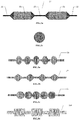
- Figures 1a-1b illustrate schematic diagrams of a stent delivery system 10 according to an embodiment of the present application, which may be used to deliver vascular stents having a large metallic surface area and a low void ratio such as the densely-netted stent mentioned above to the target position ( e.g. an opened aneurysm).
- Figure 1a is a side view and Figure 1b is a cross-sectional view.
- the stent delivery system 10 consists of a number of components, including a radiopaque tip 11, a beads component 12, a funnel component 13, and a core wire 14.
- the stent delivery system 10 may also include a marker band 15, a proximal coil 16, and a heat-shrink tube 17, as well as gluing points 18 on both ends of the radiopaque tip 11 and gluing points 19 on both ends of the proximal coil 16. These components of the stent delivery system 10 are described in details as below.
- the radiopaque tip 11 is located at the distal end of the stent delivery system 10 to ensure that the distal end of the entire stent delivery system 10 is visible under a fluoroscopic equipment, thereby facilitating identifying its position and direction of movement relative to surrounding vessels during the interventional surgery.
- the distal radiopaque tip 11 may be in a coil-like shape and may be made of platinum, platinum alloy ( e.g. 92% platinum and 8% tungsten), tantalum, radiopaque polymer materials, etc.
- the distal radiopaque tip 11 is also used to capture and fix all open ends at the distal end of the beads component 12, so as to prevent unclosed metal wires or coils from injuring blood vessels or damaging the stent during the delivering process.
- the two components may be fixed through gluing with ultraviolet (UV)-curing adhesives, epoxy, or other polymeric adhesives or through soldering with solders.
- UV ultraviolet
- the distal end of the distal radiopaque tip 11 may similarly have a gluing point 18 to cover any sharp edge that may exist on the coil of the radiopaque tip so as to avoid or minimize its damages to blood vessels.
- a covering part may be provided onto the distal radiopaque tip 11 so that all open ends at the distal end of the beads component 12 may be confined within the covering part. It would be appreciated by those skilled in the art that the distal radiopaque tip 11 may be designed in various shapes or lengths, which are not limited by the present application.
- the core wire 14 of the stent delivery system 10 is designed to have a diameter that gradually decreases from the proximal end to the distal end and a cone-shaped tip, which may allow the core wire 14 to have enough flexibility, so that the delivery system 10 and the stent can move flexibly in curved vessels and be guided to the lesion.
- the core wire 14 as a whole may be made of metals, polymers, alloys, hyper-elastic materials, or shape memory materials known in the art.
- the core wire may also be made of two or more materials. Core wires may have a number of selectable diameters, e.g. the maximum diameter at the distal end varies from 0.0127mm (0.0005") to 0.97mm (0.038”), and selectable lengths, e.g. it varies from 30cm to 300cm.
- the stent delivery system 10 may also include a heat-shrink tube 17 located outside the core wire 14.
- the heat-shrink tube 17 is located at the proximal end of the core wire 14 and is always kept outside the body of the patient during the interventional surgery so as to indicate a relative position of the entire delivery system within the body of the patient.
- the heat-shrink tube 17 is made of PET or PEBAX.
- the distal end of the beads component 12 is fixed on the distal radiopaque tip 11. Meanwhile, the proximal end of the beads component 12 is fixed on the distal end of the core wire 14. Similarly, the beads component 12 and the core wire 14 may be fixed by gluing.
- a marker band 15 and a proximal coil 16 are coupled in sequence at the outermost part of the distal end of the core wire 14.
- the marker band 15 is in a cylindrical shape and may be made of platinum alloy (e.g. 90% platinum and 10% iridium) or other radiopaque materials, so as to facilitate identifying the position of the proximal end of the stent delivery system 10 during the interventional surgery.
- the proximal coil 16 may be of stainless steel or other alloy materials. As the tip of the core wire 14 is cone-shaped and has a fine diameter, coupling the proximal coil 16 may prevent the cone-shaped tip from bending during the delivering process so as to ensure elasticity and flexibility of the core wire 14. In one embodiment, the length of the proximal coil 16 may be substantially a quarter of the length of the entire core wire 14. In addition, in one embodiment, as shown by the gluing points 19 in Figures 1a-1b , the proximal coil 16 may be fixed on the core wire 14 and glued to the marker band 15 by using materials such as heat-curing epoxy adhesives.
- the proximal coil 16, the marker band 15, and the core wire 14 may be fixed through soldering.
- the marker band 15 may project out of the distal end of the core wire 14, and the beads component 12 may be inserted from the middle ( i.e. core) such that the distal end of the core wire 14 may reach the middle of the beads component 12 as well as the middle of the stent.
- the distal end of the core wire 14 has a marker structure.
- the marker structure at the distal end of the core wire 14 may always identify relative positions of the stent to the catheter when the stent is deployed during surgery.
- the beads component 12 is designed to be placed within the stent ( e.g. the stent 51 in Figure 5a ).
- the beads component 12 may achieve the following effects: 1) once arriving at the target position, by pushing the core wire 14 towards the distal direction, the beads component 12 and the stent are pushed out of the catheter (not shown) together, and the stent is pushed to expand by the expansion of the expandable parts of the beads component 12 so that the stent may be fully deployed at the target position and thereby contact the vessel wall at the treatment position; 2) when the initial deploying position for the stent is not satisfying, by pulling the core wire 14 back towards the proximal end, the beads component 12 and the stent are pulled back to the catheter (not shown) and return to the compressed state so that the deploying position for the stent may be re-adjusted or, if necessary, the stent and its delivery system 10 may be taken out from the patient.
- Figures 2a-2b illustrate schematic diagrams of the beads component 12 according to the above-described embodiment.
- the beads component 12 is designed to have a substantially circular cross section (as shown in Figure 2b ) and varied cross-sectional diameters along its effective length.
- the beads component 12 is designed to have multiple ( e.g. two) bead-shaped expandable parts 21 and multiple ( e.g . three) non-expandable parts 22 which are arranged in an alternate structure.
- the multiple expandable parts 21 and non-expandable parts 22 are one continuous piece and may be made of Nitinol alloy or other alternative super-elastic materials, shape memory materials, or piezoelectric materials such as metals, alloys, polymers, etc.
- the beads component 12 may be braided with multiple ( e.g . six to sixty-four) Nitinol alloy wires, of which the braided density (weft density) may be correspondingly from approximately 20PPI (picks per inch) to 250PPI so as to match the braided density of the stent.
- the beads component 12 may be braided with 24 Nitinol alloy wires to have a braided density of approximately 65PPI.
- the length of each expandable part 21 in a fully deployed state, is approximately 5mm and the maximum diameter is approximately 2mm so as to match ( e.g. equal to, slightly smaller than, or smaller than) the inner diameter of the stent. Accordingly, also in this preferred embodiment, in the fully deployed state, the length of each non-expandable part 22 located in the middle of the beads component 12 is approximately 5mm, and the length of each non-expandable part 22 located at the two ends of the beads component 12 is at least 6mm. It would be appreciated by those skilled in the art that the expandable part 21 and the non-expandable 22 may also be designed to have other suitable sizes.
- the number of expandable parts 21 on the beads component 12 may be determined based on the length of the stent so that the effective length of the beads component 12 may be matched with the length of the stent. In one preferred embodiment, the number of the expandable parts 21, the non-expandable parts 22 or a combination of the two parts may vary from 1 to 40.
- the minimum cross-sectional diameter of the beads component 12 may be determined through various ways.
- the diameter of the open end at the proximal end of the beads component 12 i.e. the diameter of the non-expandable part 22 at the proximal end
- the diameter of the open end at the distal end of the beads component 12 i.e. the diameter of the non-expandable part 22 at the distal end
- the diameters of the connection ends of the expandable parts 21 and non-expandable parts 22 within the beads component 12 may also be substantially equal to the inner diameter of the marker band 15.
- the present application does not limit the designs of the beads component 12 to the embodiments described above. It would be appreciated by those skilled in the art that diameter of the non-expandable part may be flexibly determined according to the material, size, and manufacturing processing of the beads component as well as the shape of the expandable part.
- the beads components 12a and 12b are respectively designed to have expandable parts in a flat-spherical shape and a bipyramid shape, so that they may have varied cross-sectional diameters along their effective lengths.
- the non-expandable parts and other designs of the beads components 12a and 12b are similar to those of the beads component 12, which will not be deliberated again.
- Figure 3c illustrates an exemplary design 12c of the beads component, which has a spherical-shaped expandable part.
- the beads component 12c is directly formed by successively arranging multiple expandable parts and only having the non-expandable parts at the two ends of the component to connect other components of the stent delivery system.
- Manufacturing materials and process of the beads component 12c are similar to those of the beads component 12, which will not be deliberated again.
- Figure 3d illustrates an exemplary design 12d of the beads component.
- the beads component 12d is designed to be made of an elastic coil and have at least two different diameters alternately configured along its effective length. According to the above description of the beads component 12, it would be appreciated by those skilled in the art that the maximum diameter of the coil forming the beads component 12d may be designed to match the inner diameter of the stent.
- Figures 4a-4b illustrate schematic diagrams of the funnel component 13 in the stent delivery system according to an embodiment of the present application, where Figure 4a is a side view and Figure 4b is a perspective view.
- the funnel component 13 may also be made of Nitinol or other super-elastic, shape memory, or piezoelectric materials such as metals, alloys, or polymers, and may be made through fine wire braiding.
- a flare structure 41 is formed at the distal end of the funnel component 13.
- the flare structure is designed to have a substantially circular cross-section, which gradually increases from its minimum diameter to its maximum diameter along the proximal-to-distal direction. In one embodiment, the maximum diameter is designed to be larger ( e.g.
- a collapsed end 42 is formed at the proximal end of the funnel component 13.
- the collapsed end 42 is designed to have a cylindrical shape and couple to the open end at the proximal end of the beads component 12 and core wire 14 sequentially from outside to inside.
- the diameter of the collapsed end 42 may be designed according to the inner diameter of the marker band 15, so as to allow the collapsed end 42 to appropriately pass through the marker band 15 and couple to the beads component 12 and the core wire 14.
- the funnel component 13 may be made by braiding multiple ( e.g. four to twenty-four) Nitinol alloy wires, the length of the distal flare structure may vary from 2mm to 10mm and at least partially overlap with the stent in the axial direction. Alternatively, the distal flare structure may be designed to cover a part or the entire length of the stent in the compressed state. In one preferred embodiment, the funnel component 13 is braided by using sixteen Nitinol alloy wires. Accordingly, in this preferred embodiment, the length of the distal flare structure of the funnel component 13 is approximately 5mm and the maximum diameter of the flare is approximately 6mm. It would be appreciated by those skilled in the art that the funnel component 13 may have other appropriate sizes.
- the funnel component 13 is made by braiding fine wires.
- the fine wires may be bended and the bended parts may be used as the flare structure 41, so that there is no sharp tip at the open end and all opening tips are bound at one side of the collapsed end 42 to avoid or minimize damages to blood vessels.
- the funnel component 13 and the beads component 12 together may facilitate a full deployment and retrieval operation of the stent. Functions of the funnel components 13 and the beads component 12 in the operations of deploying and retrieving the stent will be described below in connection with other figures.
- Figures 5a-5c illustrate schematic diagrams of a flow diversion device 50 according an embodiment of the present application, where Figure 5a illustrates the device in a partially deployed state, Figure 5b illustrates the device in a compressed state, and Figure 5c is an enlarged partial view of Figure 5b . As shown, the flow diversion device 50 is obtained based on the stent delivery system 10.
- the flow diversion device 50 also comprises a stent 51 and an introducer tube 52.
- the stent 51 is placed outside the beads component 12. In a fully deployed state, the length of the stent may be substantially equal to or slightly smaller than the length of the beads component 12.
- the stent 51 may be manufactured by any known techniques such as braiding, coating, laser cutting, etc. and be made of any known materials such as metal, alloy, polymer, etc., which are not limited by the present application. It would be appreciated by those skilled in the art that the diameter and length of the stent 51 depend on conditions of the treatment position in the blood vessel. In one embodiment, the diameter of the stent 51 may be approximately between 2mm and 10mm, and the length may be approximately between 5mm and 100mm.
- the flow diversion device 50 shown in Figure 5a is in a partially deployed state. Under this state, a portion of the beads component 12 and the stent 51 has been pushed out of the introducer tube 52.
- the stent 51 may be expanded due to its elasticity and the radial tension of the beads component 12 so that the stent 51 may touch the vessel wall at the treatment position. Then, further advancement of the core wire 14 may fully deploy the stent in the vessel. Then, by retracting the core wire 14 towards the proximal end, the stent delivery system 10 may be pulled back to the introducer tube 52 and delivery of the stent may be completed.
- the flow diversion device 50 may be retrieved back into the catheter before the stent 51 is fully deployed.
- the flow diversion device 50 shown in Figure 5b is in a compressed state. Under this state, all components of the flow diversion device 50 are confined within the lumen of the introducer tube 52 so that the entire flow diversion device 50 is in a compressed state (also known as the initial state).
- the beads component 12 may compress due to the radial pressure so that its diameter and length in this state are smaller than those in the deployed state. Meanwhile, the radial tension generated by the compressed beads component 12 may provide friction that may make the stent 51 move, along its axis, towards the distal end for delivery or towards the proximal end for retrieval. As the beads component 12 has tapered diameters on its expandable parts, it may be easily pulled back into the catheter during the retrieving process.
- the distal flare structure of the funnel component 13 may also compress under the radial pressure.
- a part of the flare structure covering the proximal end of the stent 51 may generate radial pressure to the stent 51 and, thereby, provide friction that may make the stent 51 move along its axis for delivery or retrieve.
- the funnel component 13 may effectively cover the proximal end of the stent 51, it may prevent the proximal end of the stent 51 from being bended by the introducer tube 52 during the process of retrieving the stent 51 back into the introducer tube 52, thereby allowing re-introduction of the device into the catheter.
- Figure 5c is an enlarged partial view of Figure 5b , which illustrates relative positions of the beads component 12, the stent 51, and the funnel component 13 under the compressed state in the introducer tube 52.
- the introducer tube 52 may be used to maintain the flow diversion device 50 and the stent 51 in the initial compressed state. At the beginning of the interventional surgery, the introducer tube 52 is plugged into the head of the catheter. Both ends of the introducer tube 52 may be tapered and smooth, and the introducer tube 52 may be made of materials known in the art such as high density polyethylene (HDPE), which are not limited by the present application.
- HDPE high density polyethylene
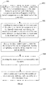
- Figure 6 illustrates a process flow of an assembly method 600 for a flow diversion device according to an embodiment of the present application.
- the method includes steps 601-605.
- step 601 coupling the core wire, the beads component, the funnel component sequentially from inside to outside, and fixing the proximal end of the beads component and the collapsed end of the funnel component onto the distal end of the core wire.
- step 602 coupling the marker band to the outer part of the core wire, the beads component, and the funnel component, and fixing the proximal coil onto the distal end of the core wire, wherein the marker band is fixed onto to the distal end of the proximal coil.
- step 603 fixing the distal radiopaque tip onto the distal end of the beads component, thereby completing assembly of the stent delivery sub-assembly.
- step 604 inserting the stent delivery sub-assembly into the stent.
- step 605 compressing and inserting the combined stent and stent delivery sub-assembly into the introducer tube.
- heat-curing epoxy adhesives may be applied at key points to glue various components together.
- ultraviolet (UV)-curing adhesives may be applied at corresponding key points.
- the assembly method 600 also includes coupling the heat-shrink tube to the proximal end of the core wire. In another embodiment, the assembly method 600 also includes sterilizing the assembled flow diversion device.
- the stent delivery system, the corresponding flow diversion device, and the assembly method of the flow diversion device provided by the present application have been described above in connection with the accompanied figures.
- the devices described above may be utilized for treatment of aneurysms and may facilitate easy deployment and retrieval of the stent. Using the devices described above may reduce risks in interventional surgeries as well as rejection rate of expensive medical equipments, thereby improving the success rate and economy of interventional treatment for aneurysms.
- the devices described above are suitable for stents of various designs and materials and do not rely on any particular design and manufacturing process of the stent, thereby also improving versatility of the devices.
Abstract
Description
- This application claims priority to Chinese Patent Application No.
201610979261.1 filed on November 8, 2016 - The present application relates to the field of intervention therapy, and more specifically, to a stent delivery system as well as a corresponding flow diversion device and an assembly method of flow diversion device.
- A vascular aneurysm is a result of lesion or injury in the arterial wall, which forms a localized or diffuse dilatation or bulge on the arterial wall and mainly shows as an expansile and pulsatile tumor. Aneurysms may occur in any blood vessel and include abdominal aortic aneurysm, cerebral aneurysm, peripheral aneurysm, visceral aneurysm, etc. The wall of an aneurysm is thin and fragile, making it prone to rupturing.
- Besides conventional conservative or surgical treatments, the interventional treatment is currently an important therapy for aneurysm. In the interventional treatment, it is a widely-used approach to place embolic materials such as detachable balloons, coils, etc. into the body of an aneurysm by using a catheter so that the speed of blood flow in the body of the aneurysm may be significantly reduced or even stopped. By this means, a thrombus may be gradually formed to embolize the body of the aneurysm in order to prevent the aneurysm from rupturing.
- However, at least the following defects exist when the interventional embolization treatment mentioned above is adopted for large (maximum diameter of more than 10mm) or huge (maximum diameter of more than 25mm) aneurysms. First, it is required to use embolic materials such as coils to densely fill the aneurysm. However, large or huge aneurysms are often wide-necked aneurysms. In such cases, coils as the embolus are very easy to project outinto the parent artery carrying the aneurysms, which may cause stenosis or even occlusion to the parent artery. Taking the cerebral aneurysm as an example, this may lead to serious consequences such as cerebral ischemia or even cerebral infarction. Second, the mass effect is common to large or huge aneurysms. The aneurysms may become larger, thereby compressing surrounding viscera and tissues and affecting their physiological functions. Although filling an aneurysm with coils may embolize the aneurysm, it cannot eliminate the mass effect caused by the aneurysm or may even worsen the mass effect.
- One type of flow diversion device that is based on a densely-netted vascular stent (only simply called "stent") came out in recent years. This type of flow diversion device may effectively overcome the above-described defects of coil embolization in treating large or huge aneurysms. After implanted to the parent artery, the flow diversion device may interrupt blood flow from the parent artery to the aneurysm by the fine mesh of the stent and cause blood in the aneurysm to clot so as to form a thrombus, thereby occluding completely the aneurysm. In addition, the flow diversion device may be provided for vascular endothelial cells to climb thereon. After the flow diversion device is covered by vascular endothelial cells, a permanent biological sealing may be formed on the neck of the aneurysm, which may help the parent artery to recover and become a normal vessel.
- However, there are still defects in the stent-based flow diversion device as described above. Taking the Pipeline™ embolization device of Medtronic PLC as an example, the stent is configured as being rotatable around the core component of the flow diversion device. Accordingly, torsional stress may be generated between the stent and the core component (e.g. the core wire) while the stent is pushed to the lesion through circuitous and curved vessels. As a consequence, when the compressed stent arrives at the lesion, it may not be able to deploy automatically due to the effect of the torsional stress. Since the torsional stress may be unpredictable, failure in deploying the stent might still exist even if the deploying is manually done by twisting the core wire.
- In addition, sharpness of a radiographic image may be limited for vessels of small diameters, which in turn may influence precision in the position where a stent is placed. In the case of the Pipeline embolization device, it would be very difficult to pull the deployed stent back to the catheter and re-adjust the placement position when the deployed stent is found at an unsatisfactory position.
- After problems like a failure in deploying the stent or an unsatisfactory placement position of the stent occur, it may need to take the entire Pipeline embolization device out, which may not only cause the expensive device out of use but also cause injury to the patient due to the larger diameter of a deployed stent.
- The technical solution to be solved by the present application is to provide a stent delivery system, a corresponding flow diversion device, and an assembly method of the flow diversion device. The flow diversion device may be used for treatment of aneurysms and have the advantage of easy deployment and retrieval of the stent.
- To solve the above technical problem, a stent delivery system is provided by the present application, said stent delivery system comprises: a radiopaque tip located at the distal end of the stent delivery system; a beads component comprising at least one expandable part; a funnel component comprising a distal flare structure and a proximal collapsed end, wherein the cross-section of the flare structure gradually increases from its minimum diameter to its maximum diameter along the proximal-to-distal direction; and a core wire located at the proximal end of the stent delivery system; and wherein the distal end of the beads component is fixed on the radiopaque tip and the proximal end of the beads component is fixed on the core wire; wherein the funnel component is coupled with the beads component and the core wire, and is fixed on the core wire through the collapsed end.
- Preferably, the beads component comprises a plurality of expandable parts and a plurality of non-expandable parts arranged alternatively along the axial direction, or, preferably, the beads component comprises a plurality of expandable parts continuously arranged continuously along the axial direction and two non-expandable parts located at the two ends. Or, preferably, the beads component comprises a coil, said coil comprising at least two portions in different diameters.
- Preferably, a proximal coil is coupled to the outermost part of the distal end of the core wire, and the proximal coil is fixed on the core wire. More preferably, a marker band is also coupled to the outermost part of the distal end of the core wire, said marker band being located at the distal end of the proximal coil and being fixed on the proximal coil.
- Preferably, a heat-shrink tube is coupled to the proximal end of the core wire.
- Preferably, the plurality of expandable parts are in at least one of a bipyramid shape, a spherical shape, a flat-spherical shape, or a long-spherical shape.
- Preferably, the beads component and the funnel component are made of super-elastic materials, shape memory materials, or piezoelectric materials.
- Preferably, the beads component and the funnel component are made through a fine wire braiding technique.
- Preferably, the beads component is braided with six to sixty-four fine wires, and the funnel component is braided with four to twenty-four fine wires. More preferably, the braided density of the beads component is between 20 PPI and 250 PPI.
- Preferably, the radiopaque tip, the beads component, the funnel component, the core wire, the marker band, and the proximal coil are fixed through gluing. More preferably, the radiopaque tip and the beads component are glued by ultraviolet (UV)-curing adhesives. Or, more preferably, the beads component, the funnel component, the core wire, the marker band, and the proximal coil are glued by heat-curing epoxy adhesives.
- Preferably, a covering part is provided on the distal radiopaque tip to confine all distal open ends of the beads component within the covering part.
- A flow diversion device is also provided by the present application, said flow diversion device comprises a stent, a stent delivery system, and an introducer tube, wherein the stent and the stent delivery system are confined in the lumen of the introducer tube under an initial state. The stent delivery system comprises: a radiopaque tip located at the distal end of the stent delivery system; a beads component comprising at least one expandable part; a funnel component comprising a distal flare structure and a proximal collapsed end, wherein the cross-section of the flare structure gradually increases from its minimum diameter to its maximum diameter along the proximal-to-distal direction; and a core wire located at the proximal end of the stent delivery system. The distal end of the beads component is fixed on the radiopaque tip and the proximal end of the beads component is fixed on the core wire; and wherein the funnel component is coupled with the beads component and the core wire, and is fixed on the core wire through the collapsed end; and wherein, under the initial state, the stent is located outside the beads component, and the flare structure of the funnel component covers at least a proximal part of the stent.
- Preferably, the number and maximum diameter of the at least one expandable part are determined respectively according to the length and diameter of the stent.
- Preferably, compared with the length and the maximum diameter under a fully deployed state, the length is shorter and the maximum diameter is smaller under the initial state for each expandable part.
- Preferably, under a fully deployed state, the maximum diameter of the flare structure of the funnel component is larger than the maximum diameter at the proximal end of the stent.
- Preferably, a proximal coil is couple to the outermost part of the distal end of the core wire, and the proximal coil is fixed on the core wire. More preferably, a marker band is also couple to the outermost part of the distal end of the core wire, said marker band being located at the distal end of the proximal coil and being fixed on the proximal coil.
- Preferably, a heat-shrink tube is coupled to the proximal end of the core wire.
- An assembly method of a flow diversion device is also provided by the present application, said assembly method comprises: coupling a core wire, a beads component, a funnel component sequentially from inside to outside, and fixing the proximal end of the beads component and the collapsed end of the funnel component onto the distal end of the core wire; coupling a marker band to the outer part of the core wire, the beads component, and the funnel component, and fixing a proximal coil onto the distal end of the core wire, wherein the marker band is fixed onto to the distal end of the proximal coil; fixing the distal end of the beads component onto a radiopaque tip, thereby completing the assembly of the stent delivery sub-assembly; inserting the stent delivery sub-assembly into a stent; compressing and inserting the combined stent and stent delivery sub-assembly into an introducer tube.
- Preferably, the fixings between the core wire, the beads component, the funnel component, the marker band, and the proximal coil are implemented by gluing with heat-curing epoxy adhesives at key points.
- Preferably, the fixing between the beads component and the radiopaque tip is implemented by gluing with ultraviolet (UV)-curing adhesives at key points.
- Preferably, the assembly method further comprises coupling the heat-shrink tube to the proximal end of the core wire
- Preferably, the assembly method further comprises sterilizing the assembled flow diversion device.
- The devices described above can be used for aneurysm treatment, wherein the stent is easily released and may be retrieved. Said devices may reduce risks in interventional surgeries, as well as rejection rate of expensive medical equipments, thereby improving the success rate and economy of interventional treatment for aneurysms. Moreover, the devices described above are suitable for stents of varied designs and materials and do not rely on any particular design and manufacturing process of the stent, thereby also improving versatility of the devices.
- The aforementioned features and other features of the application will be further described in the following paragraphs by referring to the accompanying drawings and the appended claims. It will be understood that, the accompanying drawings merely illustrate certain embodiments in accordance with the present application and should not be considered as limitation to the scope of the present application. Unless otherwise specified, the accompanying drawings need not be proportional, and similar reference characters generally denote similar elements.
-
Figures 1a-1b illustrate schematic diagrams of a stent delivery system according to an embodiment of the present application. -
Figures 2a-2b illustrate schematic diagrams of a beads component according to the above embodiment inFigures 1a-1b . -
Figures 3a-3d illustrate schematic cross-sectional views of various alternative designs of the beads component according to embodiments of the present application. -
Figures 4a-4b illustrate schematic diagrams of a funnel component according to an embodiment of the present application. -
Figures 5a-5c illustrate schematic diagrams of a flow diversion device according to an embodiment of the present application. -
Figure 6 is a process flow of an assembly method of a flow diversion device according to an embodiment of the present application. - The following detailed description refers to the accompanying drawings as a part of the present application. The illustrative embodiments described in the detailed description, the accompanying drawings and the claims are not limiting, and other embodiments may be adopted, or modifications may be made without deviating from the spirit and subject of the application. It would be appreciated that the various aspects of the application described and graphically presented herein may be arranged, replaced, combined, divided and designed in many different configurations, and these different configurations are implicitly comprised in the application.
-
Figures 1a-1b illustrate schematic diagrams of astent delivery system 10 according to an embodiment of the present application, which may be used to deliver vascular stents having a large metallic surface area and a low void ratio such as the densely-netted stent mentioned above to the target position (e.g. an opened aneurysm).Figure 1a is a side view andFigure 1b is a cross-sectional view. As shown, thestent delivery system 10 consists of a number of components, including aradiopaque tip 11, abeads component 12, afunnel component 13, and acore wire 14. Furthermore, thestent delivery system 10 may also include amarker band 15, aproximal coil 16, and a heat-shrink tube 17, as well as gluingpoints 18 on both ends of theradiopaque tip 11 and gluing points 19 on both ends of theproximal coil 16. These components of thestent delivery system 10 are described in details as below. - The
radiopaque tip 11 is located at the distal end of thestent delivery system 10 to ensure that the distal end of the entirestent delivery system 10 is visible under a fluoroscopic equipment, thereby facilitating identifying its position and direction of movement relative to surrounding vessels during the interventional surgery. As shown, in one embodiment, the distalradiopaque tip 11 may be in a coil-like shape and may be made of platinum, platinum alloy (e.g. 92% platinum and 8% tungsten), tantalum, radiopaque polymer materials, etc. - Moreover, since the
beads component 12 is preferably made of metal wires or coils, the distalradiopaque tip 11 is also used to capture and fix all open ends at the distal end of thebeads component 12, so as to prevent unclosed metal wires or coils from injuring blood vessels or damaging the stent during the delivering process. Specifically, in one embodiment, as shown by thegluing point 18 at the proximal end of the distalradiopaque tip 11 inFigure 1a , the two components may be fixed through gluing with ultraviolet (UV)-curing adhesives, epoxy, or other polymeric adhesives or through soldering with solders. In addition, in this embodiment, the distal end of the distalradiopaque tip 11 may similarly have agluing point 18 to cover any sharp edge that may exist on the coil of the radiopaque tip so as to avoid or minimize its damages to blood vessels. In another embodiment, a covering part may be provided onto the distalradiopaque tip 11 so that all open ends at the distal end of thebeads component 12 may be confined within the covering part. It would be appreciated by those skilled in the art that the distalradiopaque tip 11 may be designed in various shapes or lengths, which are not limited by the present application. - Generally, the
core wire 14 of thestent delivery system 10 is designed to have a diameter that gradually decreases from the proximal end to the distal end and a cone-shaped tip, which may allow thecore wire 14 to have enough flexibility, so that thedelivery system 10 and the stent can move flexibly in curved vessels and be guided to the lesion. Thecore wire 14 as a whole may be made of metals, polymers, alloys, hyper-elastic materials, or shape memory materials known in the art. Alternatively, the core wire may also be made of two or more materials. Core wires may have a number of selectable diameters, e.g. the maximum diameter at the distal end varies from 0.0127mm (0.0005") to 0.97mm (0.038"), and selectable lengths, e.g. it varies from 30cm to 300cm. - Furthermore, the
stent delivery system 10 may also include a heat-shrink tube 17 located outside thecore wire 14. The heat-shrink tube 17 is located at the proximal end of thecore wire 14 and is always kept outside the body of the patient during the interventional surgery so as to indicate a relative position of the entire delivery system within the body of the patient. In one preferable embodiment, the heat-shrink tube 17 is made of PET or PEBAX. - As described above, the distal end of the
beads component 12 is fixed on the distalradiopaque tip 11. Meanwhile, the proximal end of thebeads component 12 is fixed on the distal end of thecore wire 14. Similarly, thebeads component 12 and thecore wire 14 may be fixed by gluing. In the embodiment shown inFigures 1a-1b , amarker band 15 and aproximal coil 16 are coupled in sequence at the outermost part of the distal end of thecore wire 14. In this embodiment, themarker band 15 is in a cylindrical shape and may be made of platinum alloy (e.g. 90% platinum and 10% iridium) or other radiopaque materials, so as to facilitate identifying the position of the proximal end of thestent delivery system 10 during the interventional surgery. In this embodiment, theproximal coil 16 may be of stainless steel or other alloy materials. As the tip of thecore wire 14 is cone-shaped and has a fine diameter, coupling theproximal coil 16 may prevent the cone-shaped tip from bending during the delivering process so as to ensure elasticity and flexibility of thecore wire 14. In one embodiment, the length of theproximal coil 16 may be substantially a quarter of the length of theentire core wire 14. In addition, in one embodiment, as shown by the gluing points 19 inFigures 1a-1b , theproximal coil 16 may be fixed on thecore wire 14 and glued to themarker band 15 by using materials such as heat-curing epoxy adhesives. In another embodiment, theproximal coil 16, themarker band 15, and thecore wire 14 may be fixed through soldering. In another embodiment, themarker band 15 may project out of the distal end of thecore wire 14, and thebeads component 12 may be inserted from the middle (i.e. core) such that the distal end of thecore wire 14 may reach the middle of thebeads component 12 as well as the middle of the stent. In this embodiment, the distal end of thecore wire 14 has a marker structure. Thus, the marker structure at the distal end of thecore wire 14 may always identify relative positions of the stent to the catheter when the stent is deployed during surgery. - The
beads component 12 is designed to be placed within the stent (e.g. thestent 51 inFigure 5a ). During the process of interventional treatment, thebeads component 12 may achieve the following effects: 1) once arriving at the target position, by pushing thecore wire 14 towards the distal direction, thebeads component 12 and the stent are pushed out of the catheter (not shown) together, and the stent is pushed to expand by the expansion of the expandable parts of thebeads component 12 so that the stent may be fully deployed at the target position and thereby contact the vessel wall at the treatment position; 2) when the initial deploying position for the stent is not satisfying, by pulling thecore wire 14 back towards the proximal end, thebeads component 12 and the stent are pulled back to the catheter (not shown) and return to the compressed state so that the deploying position for the stent may be re-adjusted or, if necessary, the stent and itsdelivery system 10 may be taken out from the patient. -
Figures 2a-2b illustrate schematic diagrams of thebeads component 12 according to the above-described embodiment. In order to achieve the above effects, thebeads component 12 is designed to have a substantially circular cross section (as shown inFigure 2b ) and varied cross-sectional diameters along its effective length. In the embodiment shown inFigures 2a-2b , thebeads component 12 is designed to have multiple (e.g. two) bead-shapedexpandable parts 21 and multiple (e.g. three)non-expandable parts 22 which are arranged in an alternate structure. The multipleexpandable parts 21 andnon-expandable parts 22 are one continuous piece and may be made of Nitinol alloy or other alternative super-elastic materials, shape memory materials, or piezoelectric materials such as metals, alloys, polymers, etc. In one embodiment, thebeads component 12 may be braided with multiple (e.g. six to sixty-four) Nitinol alloy wires, of which the braided density (weft density) may be correspondingly from approximately 20PPI (picks per inch) to 250PPI so as to match the braided density of the stent. In one preferred embodiment, thebeads component 12 may be braided with 24 Nitinol alloy wires to have a braided density of approximately 65PPI. Accordingly, in this preferred embodiment, in a fully deployed state, the length of eachexpandable part 21 is approximately 5mm and the maximum diameter is approximately 2mm so as to match (e.g. equal to, slightly smaller than, or smaller than) the inner diameter of the stent. Accordingly, also in this preferred embodiment, in the fully deployed state, the length of eachnon-expandable part 22 located in the middle of thebeads component 12 is approximately 5mm, and the length of eachnon-expandable part 22 located at the two ends of thebeads component 12 is at least 6mm. It would be appreciated by those skilled in the art that theexpandable part 21 and the non-expandable 22 may also be designed to have other suitable sizes. In addition, it would also be appreciated by those skilled in the art that the number ofexpandable parts 21 on thebeads component 12 may be determined based on the length of the stent so that the effective length of thebeads component 12 may be matched with the length of the stent. In one preferred embodiment, the number of theexpandable parts 21, thenon-expandable parts 22 or a combination of the two parts may vary from 1 to 40. - The minimum cross-sectional diameter of the
beads component 12 may be determined through various ways. In the embodiment shown inFigures 2a-2b , the diameter of the open end at the proximal end of the beads component 12 (i.e. the diameter of thenon-expandable part 22 at the proximal end) may be designed according to the inner diameter of thecylindrical marker band 15, so that the open end of thebeads component 12 can appropriately pass through themarker band 15 and then be coupled to thecore wire 14. Similarly, the diameter of the open end at the distal end of the beads component 12 (i.e. the diameter of thenon-expandable part 22 at the distal end) may be substantially equal to the diameter at the proximal end of the distalradiopaque tip 11 so as to fix the two. For the purpose of easy manufacturing, in the embodiment shown inFigures 2a-2b , the diameters of the connection ends of theexpandable parts 21 andnon-expandable parts 22 within thebeads component 12 may also be substantially equal to the inner diameter of themarker band 15. However, the present application does not limit the designs of thebeads component 12 to the embodiments described above. It would be appreciated by those skilled in the art that diameter of the non-expandable part may be flexibly determined according to the material, size, and manufacturing processing of the beads component as well as the shape of the expandable part. - Now turning to
Figures 3a-3d , illustrated are schematic cross-sectional views of variousalternative designs 12a-12d of the beads component according to embodiments of the present application. It would be appreciated by those skilled in the art that these alternative designs are only for illustration but not to limit the scope of the present application. - In
Figures 3a and 3b , thebeads components beads components beads component 12, which will not be deliberated again. -
Figure 3c illustrates anexemplary design 12c of the beads component, which has a spherical-shaped expandable part. Different from the designs inFigures 2a-2b and Figures 3a-3b , there is no corresponding non-expandable part between expandable parts inbeads component 12c, that is, the beads component is directly formed by successively arranging multiple expandable parts and only having the non-expandable parts at the two ends of the component to connect other components of the stent delivery system. Manufacturing materials and process of thebeads component 12c are similar to those of thebeads component 12, which will not be deliberated again. -
Figure 3d illustrates anexemplary design 12d of the beads component. Different from the manufacturing process forbeads components beads component 12d is designed to be made of an elastic coil and have at least two different diameters alternately configured along its effective length. According to the above description of thebeads component 12, it would be appreciated by those skilled in the art that the maximum diameter of the coil forming thebeads component 12d may be designed to match the inner diameter of the stent. - Various exemplary implementations of the beads component in the stent delivery system have been described in connection with
Figures 2a-2b and Figures 3a-3d . It would be appreciated by those skilled in the art that expandable parts in other shapes or a combination of expandable parts and non-expandable parts in different shapes may be used to form the beads component according to the present application, and these potential designs that may facilitate opening of the stent also fall into the scope of the present application. -
Figures 4a-4b illustrate schematic diagrams of thefunnel component 13 in the stent delivery system according to an embodiment of the present application, whereFigure 4a is a side view andFigure 4b is a perspective view. Similar to thebeads component 12, thefunnel component 13 may also be made of Nitinol or other super-elastic, shape memory, or piezoelectric materials such as metals, alloys, or polymers, and may be made through fine wire braiding. As shown, aflare structure 41 is formed at the distal end of thefunnel component 13. The flare structure is designed to have a substantially circular cross-section, which gradually increases from its minimum diameter to its maximum diameter along the proximal-to-distal direction. In one embodiment, the maximum diameter is designed to be larger (e.g. slightly larger) than the maximum diameter at the proximal end of the stent in a fully deployed state so as to completely cover the proximal end of the stent. Acollapsed end 42 is formed at the proximal end of thefunnel component 13. Thecollapsed end 42 is designed to have a cylindrical shape and couple to the open end at the proximal end of thebeads component 12 andcore wire 14 sequentially from outside to inside. The diameter of thecollapsed end 42 may be designed according to the inner diameter of themarker band 15, so as to allow thecollapsed end 42 to appropriately pass through themarker band 15 and couple to thebeads component 12 and thecore wire 14. - In one embodiment, the
funnel component 13 may be made by braiding multiple (e.g. four to twenty-four) Nitinol alloy wires, the length of the distal flare structure may vary from 2mm to 10mm and at least partially overlap with the stent in the axial direction. Alternatively, the distal flare structure may be designed to cover a part or the entire length of the stent in the compressed state. In one preferred embodiment, thefunnel component 13 is braided by using sixteen Nitinol alloy wires. Accordingly, in this preferred embodiment, the length of the distal flare structure of thefunnel component 13 is approximately 5mm and the maximum diameter of the flare is approximately 6mm. It would be appreciated by those skilled in the art that thefunnel component 13 may have other appropriate sizes. In another preferred embodiment, thefunnel component 13 is made by braiding fine wires. The fine wires may be bended and the bended parts may be used as theflare structure 41, so that there is no sharp tip at the open end and all opening tips are bound at one side of thecollapsed end 42 to avoid or minimize damages to blood vessels. - The
funnel component 13 and thebeads component 12 together may facilitate a full deployment and retrieval operation of the stent. Functions of thefunnel components 13 and thebeads component 12 in the operations of deploying and retrieving the stent will be described below in connection with other figures. -
Figures 5a-5c illustrate schematic diagrams of aflow diversion device 50 according an embodiment of the present application, whereFigure 5a illustrates the device in a partially deployed state,Figure 5b illustrates the device in a compressed state, andFigure 5c is an enlarged partial view ofFigure 5b . As shown, theflow diversion device 50 is obtained based on thestent delivery system 10. More specifically, besides the distalradiopaque tip 11, thebeads component 12, thefunnel component 13, the core wire 14 (not shown inFigure 5a ), theproximal marker band 15, theproximal coil 16, the heat-shrink tube 17 (not shown inFigure 5a ), the gluing points 18 on both ends of the distalradiopaque tip 11 and the gluing points 19 on both ends of theproximal coil 16 that form thestent delivery system 10, theflow diversion device 50 also comprises astent 51 and anintroducer tube 52. - The
stent 51 is placed outside thebeads component 12. In a fully deployed state, the length of the stent may be substantially equal to or slightly smaller than the length of thebeads component 12. Thestent 51 may be manufactured by any known techniques such as braiding, coating, laser cutting, etc. and be made of any known materials such as metal, alloy, polymer, etc., which are not limited by the present application. It would be appreciated by those skilled in the art that the diameter and length of thestent 51 depend on conditions of the treatment position in the blood vessel. In one embodiment, the diameter of thestent 51 may be approximately between 2mm and 10mm, and the length may be approximately between 5mm and 100mm. - The
flow diversion device 50 shown inFigure 5a is in a partially deployed state. Under this state, a portion of thebeads component 12 and thestent 51 has been pushed out of theintroducer tube 52. Thestent 51 may be expanded due to its elasticity and the radial tension of thebeads component 12 so that thestent 51 may touch the vessel wall at the treatment position. Then, further advancement of thecore wire 14 may fully deploy the stent in the vessel. Then, by retracting thecore wire 14 towards the proximal end, thestent delivery system 10 may be pulled back to theintroducer tube 52 and delivery of the stent may be completed. - Accordingly, based on the structural design of the
beads component 12 and thefunnel component 13, theflow diversion device 50 may be retrieved back into the catheter before thestent 51 is fully deployed. - The
flow diversion device 50 shown inFigure 5b is in a compressed state. Under this state, all components of theflow diversion device 50 are confined within the lumen of theintroducer tube 52 so that the entireflow diversion device 50 is in a compressed state (also known as the initial state). - Under this state, the
beads component 12 may compress due to the radial pressure so that its diameter and length in this state are smaller than those in the deployed state. Meanwhile, the radial tension generated by the compressedbeads component 12 may provide friction that may make thestent 51 move, along its axis, towards the distal end for delivery or towards the proximal end for retrieval. As thebeads component 12 has tapered diameters on its expandable parts, it may be easily pulled back into the catheter during the retrieving process. - Meanwhile, under this state, the distal flare structure of the
funnel component 13 may also compress under the radial pressure. As the flare structure at least partially overlaps with thestent 51 along its axis, a part of the flare structure covering the proximal end of thestent 51 may generate radial pressure to thestent 51 and, thereby, provide friction that may make thestent 51 move along its axis for delivery or retrieve. In addition, as thefunnel component 13 may effectively cover the proximal end of thestent 51, it may prevent the proximal end of thestent 51 from being bended by theintroducer tube 52 during the process of retrieving thestent 51 back into theintroducer tube 52, thereby allowing re-introduction of the device into the catheter. -
Figure 5c is an enlarged partial view ofFigure 5b , which illustrates relative positions of thebeads component 12, thestent 51, and thefunnel component 13 under the compressed state in theintroducer tube 52. - The
introducer tube 52 may be used to maintain theflow diversion device 50 and thestent 51 in the initial compressed state. At the beginning of the interventional surgery, theintroducer tube 52 is plugged into the head of the catheter. Both ends of theintroducer tube 52 may be tapered and smooth, and theintroducer tube 52 may be made of materials known in the art such as high density polyethylene (HDPE), which are not limited by the present application. -
Figure 6 illustrates a process flow of anassembly method 600 for a flow diversion device according to an embodiment of the present application. The method includes steps 601-605. - At
step 601, coupling the core wire, the beads component, the funnel component sequentially from inside to outside, and fixing the proximal end of the beads component and the collapsed end of the funnel component onto the distal end of the core wire. - At
step 602, coupling the marker band to the outer part of the core wire, the beads component, and the funnel component, and fixing the proximal coil onto the distal end of the core wire, wherein the marker band is fixed onto to the distal end of the proximal coil. - At
step 603, fixing the distal radiopaque tip onto the distal end of the beads component, thereby completing assembly of the stent delivery sub-assembly. - At
step 604, inserting the stent delivery sub-assembly into the stent. - At
step 605, compressing and inserting the combined stent and stent delivery sub-assembly into the introducer tube. - In one embodiment, in
steps step 603, ultraviolet (UV)-curing adhesives may be applied at corresponding key points. - In one embodiment, the
assembly method 600 also includes coupling the heat-shrink tube to the proximal end of the core wire. In another embodiment, theassembly method 600 also includes sterilizing the assembled flow diversion device. - The stent delivery system, the corresponding flow diversion device, and the assembly method of the flow diversion device provided by the present application have been described above in connection with the accompanied figures. The devices described above may be utilized for treatment of aneurysms and may facilitate easy deployment and retrieval of the stent. Using the devices described above may reduce risks in interventional surgeries as well as rejection rate of expensive medical equipments, thereby improving the success rate and economy of interventional treatment for aneurysms. Moreover, the devices described above are suitable for stents of various designs and materials and do not rely on any particular design and manufacturing process of the stent, thereby also improving versatility of the devices.
- The previous description of the disclosed embodiments is provided to enable any person skilled in the art to make or use the present application. Various modifications to these embodiments will be readily apparent to those skilled in the art, and the generic principles defined herein may be applied to other embodiments without departing from the spirit or scope of the invention. Thus, the present application is not intended to be limited to the embodiments shown herein but is to be accorded the widest scope consistent with the principles and novel features disclosed herein.
- Furthermore, although the operation of a method according to the present application is illustrated with reference to the accompanying drawings in a specific sequence, the present application may be practiced using process flows that differ from that illustrated. Additionally, it should be noted that not all steps are required in every embodiment. In other words, one or more of the steps may be omitted or replaced, without departing from the spirit and scope of the invention. In certain embodiments, steps may be performed in different order, in parallel with one another, or omitted entirely, and/or certain additional steps may be performed without departing from the scope of the present application.
- In the claims, the word "comprising" does not exclude other elements or steps, and the indefinite article "a" or "an" does not exclude a plurality.
Claims (19)
- A stent delivery system, characterized in that, comprising:a radiopaque tip located at the distal end of the stent delivery system;a beads component comprising at least one expandable part;a funnel component comprising a distal flare structure and a proximal collapsed end, wherein the cross-section of the flare structure gradually increases from its minimum diameter to its maximum diameter along the proximal-to-distal direction; a core wire located at the proximal end of the stent delivery system; andwherein the distal end of the beads component is fixed on the radiopaque tip and the proximal end of the beads component is fixed on the core wire;wherein the funnel component is coupled with the beads component and the core wire, and is fixed on the core wire through the collapsed end, that preferably the beads component comprises a plurality of expandable parts and a plurality of non-expandable parts arranged alternatively in the axial direction, that preferably the beads component comprises a plurality of expandable parts arranged continuously along the axial direction and two non-expandable parts located at the two ends and that preferably the beads component comprises a coil, wherein the coil comprises at least two portions in different diameters.
- The stent delivery system of claim 1, characterized in that, a proximal coil is coupled to the outermost part of the distal end of the core wire, and the proximal coil is fixed on the core wire.
- The stent delivery system of claim 2, characterized in that, a marker band is also coupled to the outermost part of the distal end of the core wire, the marker band being located at the distal end of the proximal coil and being fixed on the proximal coil.
- The stent delivery system of claim 1, characterized in that, a heat-shrink tube is coupled to the proximal end of the core wire.
- The stent delivery system of claim 1, characterized in that, the plurality of expandable parts are in at least one of a bipyramid shape, a spherical shape, a flat-spherical shape, or a long-spherical shape.
- The stent delivery system of claim 1, characterized in that, the beads component and the funnel component are made of super-elastic materials, shape memory materials, or piezoelectric materials.
- The stent delivery system of claim 1, characterized in that, the beads component and the funnel component are made through a fine wire braiding technique.
- The stent delivery system of claim 7, characterized in that, the beads component is braided with six to sixty-four fine wires, and the funnel component is braided with four to twenty-four fine wires, whereas preferably the braided density of the beads component is between 20 PPI and 250 PPI.
- The stent delivery system of claim 1, 2, or 3, characterized in that, the radiopaque tip, the beads component, the funnel component, the core wire, the marker band, and the proximal coil are fixed through gluing, whereas preferably the radiopaque tip and the beads component are glued by ultraviolet (UV)-curing adhesives.
- The stent delivery system of claim 9, characterized in that, the beads component, the funnel component, the core wire, the marker band, and the proximal coil are glued by heat-curing epoxy adhesives.
- The stent delivery system of claim 1, characterized in that, a covering part is provided on the radiopaque tip to confine all open ends at the distal end of the beads component within the covering part.
- A flow diversion device, comprising a stent, a stent delivery system, and an introducer tube, wherein the stent and the stent delivery system are confined within the lumen of the introducer tube under an initial state, characterized in that,
the stent delivery system comprises: a radiopaque tip located at the distal end of the stent delivery system; a beads component comprising at least one expandable part; a funnel component comprising a distal flare structure and a proximal collapsed end, wherein the cross-section of the flare structure gradually increases from its minimum diameter to its maximum diameter along the proximal-to-distal direction; and a core wire located at the proximal end of the stent delivery system; and
wherein the distal end of the beads component is fixed on the radiopaque tip and the proximal end of the beads component is fixed on the core wire; and wherein the funnel component is coupled with the beads component and the core wire, and is fixed on the core wire through the collapsed end; and
wherein, under the initial state, the stent is located outside the beads component, and the flare structure of the funnel component covers at least a proximal part of the stent, that preferably the number and maximum diameter of the at least one expandable part are determined respectively according to the length and diameter of the stent. - The flow diversion device of claim 12, characterized in that, compared with the length and the maximum diameter under a fully deployed state, the length is shorter and the maximum diameter is smaller under the initial state for each expandable part, whereas preferably under a fully deployed state, the maximum diameter of the flare structure of the funnel component is larger than the maximum diameter at the proximal end of the stent.
- The flow diversion device of claim 12, characterized in that, a proximal coil is couple to the outermost part of the distal end of the core wire, and the proximal coil is fixed on the core wire, whereas preferably a marker band is also couple to the outermost part of the distal end of the core wire, the marker band being located at the distal end of the proximal coil and being fixed on the proximal coil.
- The flow diversion device of claim 12, characterized in that, a heat-shrink tube is coupled to the proximal end of the core wire.
- An assembly method of a flow diversion device, characterized in that, comprising,
step 1601, coupling a core wire, a beads component, a funnel component sequentially from inside to outside, and fixing the proximal end of the beads component and the collapsed end of the funnel component onto the distal end of the core wire,
step 1602, coupling a marker band to the outer part of the core wire, the beads component, and the funnel component, and fixing a proximal coil onto the distal end of the core wire, wherein the marker band is fixed onto to the distal end of the proximal coil,
step 1603, fixing a radiopaque tip onto the distal end of the beads component, thereby completing assembly of the stent delivery sub-assembly,
step 1604, inserting the stent delivery sub-assembly into a stent,
step 1605, compressing and inserting the combined stent and stent delivery sub-assembly into an introducer tube. - The assembly method of claim 16, characterized in that, in steps 2401 and 2402, the fixings are implemented by gluing with heat-curing epoxy adhesives at key points.
- The assembly method of claim 16, characterized in that, in step 2403, the fixing is implemented by gluing with ultraviolet (UV)-curing adhesives at key points, whereas preferably the method further comprises coupling the heat-shrink tube to the proximal end of the core wire.
- The assembly method of claim 16, characterized in that, it further comprises sterilizing the assembled flow diversion device.
Applications Claiming Priority (1)
| Application Number | Priority Date | Filing Date | Title |
|---|---|---|---|
| CN201610979261.1A CN108056798B (en) | 2016-11-08 | 2016-11-08 | Support pushing system, corresponding blood flow guiding device and blood flow guiding device assembling method |
Publications (2)
| Publication Number | Publication Date |
|---|---|
| EP3318224A1 true EP3318224A1 (en) | 2018-05-09 |
| EP3318224B1 EP3318224B1 (en) | 2020-05-13 |
Family
ID=60452367
Family Applications (1)
| Application Number | Title | Priority Date | Filing Date |
|---|---|---|---|
| EP17200640.5A Active EP3318224B1 (en) | 2016-11-08 | 2017-11-08 | Stent delivery system, corresponding flow diversion device, and assembly method of flow diversion device |
Country Status (5)
| Country | Link |
|---|---|
| US (1) | US10624771B2 (en) |
| EP (1) | EP3318224B1 (en) |
| CN (1) | CN108056798B (en) |
| ES (1) | ES2807754T3 (en) |
| WO (1) | WO2018086464A1 (en) |
Cited By (2)
| Publication number | Priority date | Publication date | Assignee | Title |
|---|---|---|---|---|
| CN111084664A (en) * | 2018-10-24 | 2020-05-01 | 先健科技(深圳)有限公司 | Radiopacity system |
| CN116098742A (en) * | 2023-04-11 | 2023-05-12 | 杭州启明医疗器械股份有限公司 | Sheath tube and conveying system convenient for recovering artificial implant |
Families Citing this family (50)
| Publication number | Priority date | Publication date | Assignee | Title |
|---|---|---|---|---|
| US8425549B2 (en) | 2002-07-23 | 2013-04-23 | Reverse Medical Corporation | Systems and methods for removing obstructive matter from body lumens and treating vascular defects |
| EP1750619B1 (en) | 2004-05-25 | 2013-07-24 | Covidien LP | Flexible vascular occluding device |
| US9675476B2 (en) | 2004-05-25 | 2017-06-13 | Covidien Lp | Vascular stenting for aneurysms |
| CA2758946C (en) | 2004-05-25 | 2014-10-21 | Tyco Healthcare Group Lp | Vascular stenting for aneurysms |
| US8152833B2 (en) | 2006-02-22 | 2012-04-10 | Tyco Healthcare Group Lp | Embolic protection systems having radiopaque filter mesh |
| EP2460478B1 (en) | 2008-04-21 | 2021-09-08 | Covidien LP | Braid-ball embolic devices and delivery systems |
| US9675482B2 (en) | 2008-05-13 | 2017-06-13 | Covidien Lp | Braid implant delivery systems |
| US8409269B2 (en) | 2009-12-21 | 2013-04-02 | Covidien Lp | Procedures for vascular occlusion |
| US8974512B2 (en) | 2010-09-10 | 2015-03-10 | Medina Medical, Inc. | Devices and methods for the treatment of vascular defects |
| US8998947B2 (en) | 2010-09-10 | 2015-04-07 | Medina Medical, Inc. | Devices and methods for the treatment of vascular defects |
| WO2012078678A1 (en) | 2010-12-06 | 2012-06-14 | Tyco Healthcare Group Lp | Vascular remodeling device |
| US9089332B2 (en) | 2011-03-25 | 2015-07-28 | Covidien Lp | Vascular remodeling device |
| AU2012253583B2 (en) | 2011-05-11 | 2014-09-25 | Covidien Lp | Vascular remodeling device |
| WO2013049448A1 (en) | 2011-09-29 | 2013-04-04 | Covidien Lp | Vascular remodeling device |
| US9072620B2 (en) | 2011-11-04 | 2015-07-07 | Covidien Lp | Protuberant aneurysm bridging device deployment method |
| US9011480B2 (en) | 2012-01-20 | 2015-04-21 | Covidien Lp | Aneurysm treatment coils |
| US9452070B2 (en) | 2012-10-31 | 2016-09-27 | Covidien Lp | Methods and systems for increasing a density of a region of a vascular device |
| CN108354645A (en) | 2012-11-13 | 2018-08-03 | 柯惠有限合伙公司 | plugging device |
| EP2967571B1 (en) | 2013-03-15 | 2022-08-31 | Covidien LP | Occlusive device |
| WO2014145012A2 (en) | 2013-03-15 | 2014-09-18 | Covidien Lp | Delivery and detachment mechanisms for vascular implants |
| WO2015073704A1 (en) | 2013-11-13 | 2015-05-21 | Covidien Lp | Galvanically assisted attachment of medical devices to thrombus |
| US9713475B2 (en) | 2014-04-18 | 2017-07-25 | Covidien Lp | Embolic medical devices |
| US9814466B2 (en) | 2014-08-08 | 2017-11-14 | Covidien Lp | Electrolytic and mechanical detachment for implant delivery systems |
| US10478194B2 (en) | 2015-09-23 | 2019-11-19 | Covidien Lp | Occlusive devices |
| US10314593B2 (en) | 2015-09-23 | 2019-06-11 | Covidien Lp | Occlusive devices |
| US10893869B2 (en) | 2016-03-24 | 2021-01-19 | Covidien Lp | Thin wall constructions for vascular flow diversion |
| US10828039B2 (en) | 2016-06-27 | 2020-11-10 | Covidien Lp | Electrolytic detachment for implantable devices |
| US10828037B2 (en) | 2016-06-27 | 2020-11-10 | Covidien Lp | Electrolytic detachment with fluid electrical connection |
| US11051822B2 (en) | 2016-06-28 | 2021-07-06 | Covidien Lp | Implant detachment with thermal activation |
| US10478195B2 (en) | 2016-08-04 | 2019-11-19 | Covidien Lp | Devices, systems, and methods for the treatment of vascular defects |
| US10576099B2 (en) | 2016-10-21 | 2020-03-03 | Covidien Lp | Injectable scaffold for treatment of intracranial aneurysms and related technology |
| US10675036B2 (en) | 2017-08-22 | 2020-06-09 | Covidien Lp | Devices, systems, and methods for the treatment of vascular defects |
| US11065136B2 (en) | 2018-02-08 | 2021-07-20 | Covidien Lp | Vascular expandable devices |
| US11065009B2 (en) | 2018-02-08 | 2021-07-20 | Covidien Lp | Vascular expandable devices |
| US10905432B2 (en) | 2018-08-22 | 2021-02-02 | Covidien Lp | Aneurysm treatment coils and associated systems and methods of use |
| US10912569B2 (en) | 2018-08-22 | 2021-02-09 | Covidien Lp | Aneurysm treatment coils and associated systems and methods of use |
| CN110960341A (en) * | 2018-09-29 | 2020-04-07 | 上海心瑞医疗科技有限公司 | Support conveying system |
| CN111388044A (en) | 2018-12-17 | 2020-07-10 | 柯惠有限合伙公司 | Occlusion device |
| CN111374798B (en) * | 2018-12-27 | 2021-12-03 | 先健科技(深圳)有限公司 | Interventional guiding device |
| US11498165B2 (en) | 2019-11-04 | 2022-11-15 | Covidien Lp | Systems and methods for treating aneurysms |
| US11931041B2 (en) | 2020-05-12 | 2024-03-19 | Covidien Lp | Devices, systems, and methods for the treatment of vascular defects |
| WO2022089292A1 (en) * | 2020-10-30 | 2022-05-05 | 艾柯医疗器械(北京)有限公司 | Bead-string-shaped component, manufacturing method therefor and use thereof |
| CN112263363A (en) * | 2020-12-03 | 2021-01-26 | 李立 | Support wall sticking device |
| CN112690854B (en) * | 2020-12-30 | 2023-09-19 | 广州易介医疗科技有限公司 | Conveying system of blood flow reconstruction support |
| US11134954B1 (en) * | 2021-02-01 | 2021-10-05 | Accumedical Beijing Ltd. | Braided embolization apparatus |
| CN114451946A (en) * | 2021-08-23 | 2022-05-10 | 上海心玮医疗科技股份有限公司 | Carry seal wire and blood flow guider |
| CN114081570B (en) * | 2021-12-08 | 2024-03-08 | 杭州拓脉医疗科技有限公司 | Spring ring for embolizing aneurysm and blood vessel |
| CN114748226A (en) * | 2022-04-24 | 2022-07-15 | 上海心玮医疗科技股份有限公司 | Blood flow guiding device |
| CN115813628B (en) * | 2023-02-07 | 2023-05-05 | 艾柯医疗器械(北京)股份有限公司 | Bead string-shaped part and bracket conveying part comprising same |
| CN115998496B (en) * | 2023-03-27 | 2023-05-26 | 艾柯医疗器械(北京)股份有限公司 | Segmented expansion member, delivery device and vascular implant system incorporating the same |
Citations (5)
| Publication number | Priority date | Publication date | Assignee | Title |
|---|---|---|---|---|
| EP0696447A2 (en) * | 1994-08-12 | 1996-02-14 | Cardiovascular Concepts, Inc. | Apparatus and methods for deployment release of intraluminal prostheses |
| US20090270974A1 (en) * | 2004-05-25 | 2009-10-29 | Chestnut Medical Technologies, Inc. | Vascular stenting for aneurysms |
| WO2011014814A2 (en) * | 2009-07-30 | 2011-02-03 | Boston Scientific Scimed, Inc. | Stent delivery system |
| US20110245917A1 (en) * | 2010-03-30 | 2011-10-06 | Medtronic, Inc. | Transcatheter Prosthetic Heart Valve Delivery System With Recapturing Feature and Method |
| EP3011938A1 (en) * | 2014-10-08 | 2016-04-27 | Asahi Intecc Co., Ltd. | Pusher guide wire |
Family Cites Families (12)
| Publication number | Priority date | Publication date | Assignee | Title |
|---|---|---|---|---|
| CN1775190B (en) * | 1999-01-27 | 2010-06-16 | 梅德特龙尼克有限公司 | Cardiac valve procedure methods and devices |
| US7879062B2 (en) * | 2003-07-22 | 2011-02-01 | Lumen Biomedical, Inc. | Fiber based embolism protection device |
| US20070043420A1 (en) * | 2005-08-17 | 2007-02-22 | Medtronic Vascular, Inc. | Apparatus and method for stent-graft release using a cap |
| EP2211972B1 (en) * | 2007-10-26 | 2015-12-23 | Embolitech, LLC | Intravascular guidewire filter system for pulmonary embolism protection and embolism removal or maceration |
| CN102188300B (en) * | 2010-03-02 | 2014-05-28 | 上海微创医疗器械(集团)有限公司 | Aneurismal surgical device |
| RU2727037C2 (en) * | 2010-11-03 | 2020-07-17 | Колопласт А/С | Urological device |
| US20120172964A1 (en) * | 2010-12-30 | 2012-07-05 | Boston Scientific Scimed, Inc. | Stent Loading and Delivery Device Having a Loading Basket Lock Mechanism |
| US9078659B2 (en) * | 2012-04-23 | 2015-07-14 | Covidien Lp | Delivery system with hooks for resheathability |
| US9566412B2 (en) * | 2014-01-03 | 2017-02-14 | Legacy Ventures LLC | Method of manufacturing a catheter-delivered medical device from a tube |
| CN204446084U (en) * | 2014-11-28 | 2015-07-08 | 贝尔泰克医疗器械江苏有限公司 | A kind of high-intensity hollow bone screw |
| CN105816215A (en) * | 2015-12-10 | 2016-08-03 | 北京泰杰伟业科技有限公司 | Regional blood flow guiding device as well as preparation method and use method thereof |
| CN206491831U (en) * | 2016-11-08 | 2017-09-15 | 吕怡然 | Stent pushing system and corresponding blood flow guider |
-
2016
- 2016-11-08 CN CN201610979261.1A patent/CN108056798B/en active Active
-
2017
- 2017-07-05 US US15/641,580 patent/US10624771B2/en active Active
- 2017-10-27 WO PCT/CN2017/108023 patent/WO2018086464A1/en active Application Filing
- 2017-11-08 ES ES17200640T patent/ES2807754T3/en active Active
- 2017-11-08 EP EP17200640.5A patent/EP3318224B1/en active Active
Patent Citations (5)
| Publication number | Priority date | Publication date | Assignee | Title |
|---|---|---|---|---|
| EP0696447A2 (en) * | 1994-08-12 | 1996-02-14 | Cardiovascular Concepts, Inc. | Apparatus and methods for deployment release of intraluminal prostheses |
| US20090270974A1 (en) * | 2004-05-25 | 2009-10-29 | Chestnut Medical Technologies, Inc. | Vascular stenting for aneurysms |
| WO2011014814A2 (en) * | 2009-07-30 | 2011-02-03 | Boston Scientific Scimed, Inc. | Stent delivery system |
| US20110245917A1 (en) * | 2010-03-30 | 2011-10-06 | Medtronic, Inc. | Transcatheter Prosthetic Heart Valve Delivery System With Recapturing Feature and Method |
| EP3011938A1 (en) * | 2014-10-08 | 2016-04-27 | Asahi Intecc Co., Ltd. | Pusher guide wire |
Cited By (4)
| Publication number | Priority date | Publication date | Assignee | Title |
|---|---|---|---|---|
| CN111084664A (en) * | 2018-10-24 | 2020-05-01 | 先健科技(深圳)有限公司 | Radiopacity system |
| CN111084664B (en) * | 2018-10-24 | 2021-08-03 | 元心科技(深圳)有限公司 | Radiopacity system |
| CN116098742A (en) * | 2023-04-11 | 2023-05-12 | 杭州启明医疗器械股份有限公司 | Sheath tube and conveying system convenient for recovering artificial implant |
| CN116098742B (en) * | 2023-04-11 | 2023-07-11 | 杭州启明医疗器械股份有限公司 | Sheath tube and conveying system convenient for recovering artificial implant |
Also Published As
| Publication number | Publication date |
|---|---|
| CN108056798A (en) | 2018-05-22 |
| CN108056798B (en) | 2021-06-04 |
| WO2018086464A1 (en) | 2018-05-17 |
| ES2807754T3 (en) | 2021-02-24 |
| US10624771B2 (en) | 2020-04-21 |
| US20180125686A1 (en) | 2018-05-10 |
| EP3318224B1 (en) | 2020-05-13 |
Similar Documents
| Publication | Publication Date | Title |
|---|---|---|
| EP3318224B1 (en) | Stent delivery system, corresponding flow diversion device, and assembly method of flow diversion device | |
| US10322018B2 (en) | System and method for delivering and deploying an occluding device within a vessel | |
| US8636760B2 (en) | System and method for delivering and deploying an occluding device within a vessel | |
| US10064747B2 (en) | System and method for delivering and deploying an occluding device within a vessel | |
| AU2013271845B2 (en) | Aneurysm occlusion system and method | |
| US11497895B2 (en) | Expandable tip medical devices and methods | |
| CA2961431C (en) | An embolisation device | |
| US11399845B2 (en) | Vascular cages and methods of making and using the same | |
| EP3052059B1 (en) | Stents twisted prior to deployment and untwisted during deployment | |
| CN116648201B (en) | Vascular occlusion device and method of manufacturing the same | |
| US20230263530A1 (en) | Neurovascular Flow Diverter and Delivery Systems |
Legal Events
| Date | Code | Title | Description |
|---|---|---|---|
| PUAI | Public reference made under article 153(3) epc to a published international application that has entered the european phase |
Free format text: ORIGINAL CODE: 0009012 |
|
| STAA | Information on the status of an ep patent application or granted ep patent |
Free format text: STATUS: THE APPLICATION HAS BEEN PUBLISHED |
|
| AK | Designated contracting states |
Kind code of ref document: A1 Designated state(s): AL AT BE BG CH CY CZ DE DK EE ES FI FR GB GR HR HU IE IS IT LI LT LU LV MC MK MT NL NO PL PT RO RS SE SI SK SM TR |
|
| AX | Request for extension of the european patent |
Extension state: BA ME |
|
| STAA | Information on the status of an ep patent application or granted ep patent |
Free format text: STATUS: REQUEST FOR EXAMINATION WAS MADE |
|
| 17P | Request for examination filed |
Effective date: 20181017 |
|
| RBV | Designated contracting states (corrected) |
Designated state(s): AL AT BE BG CH CY CZ DE DK EE ES FI FR GB GR HR HU IE IS IT LI LT LU LV MC MK MT NL NO PL PT RO RS SE SI SK SM TR |
|
| GRAP | Despatch of communication of intention to grant a patent |
Free format text: ORIGINAL CODE: EPIDOSNIGR1 |
|
| RAP1 | Party data changed (applicant data changed or rights of an application transferred) |
Owner name: ACCUMEDICAL BEIJING LTD. |
|
| RIN1 | Information on inventor provided before grant (corrected) |
Inventor name: LU, YIRAN |
|
| STAA | Information on the status of an ep patent application or granted ep patent |
Free format text: STATUS: GRANT OF PATENT IS INTENDED |
|
| INTG | Intention to grant announced |
Effective date: 20191121 |
|
| GRAS | Grant fee paid |
Free format text: ORIGINAL CODE: EPIDOSNIGR3 |
|
| GRAA | (expected) grant |
Free format text: ORIGINAL CODE: 0009210 |
|
| STAA | Information on the status of an ep patent application or granted ep patent |
Free format text: STATUS: THE PATENT HAS BEEN GRANTED |
|
| AK | Designated contracting states |
Kind code of ref document: B1 Designated state(s): AL AT BE BG CH CY CZ DE DK EE ES FI FR GB GR HR HU IE IS IT LI LT LU LV MC MK MT NL NO PL PT RO RS SE SI SK SM TR |
|
| REG | Reference to a national code |
Ref country code: GB Ref legal event code: FG4D |
|
| REG | Reference to a national code |
Ref country code: CH Ref legal event code: EP |
|
| REG | Reference to a national code |
Ref country code: DE Ref legal event code: R096 Ref document number: 602017016403 Country of ref document: DE |
|
| REG | Reference to a national code |
Ref country code: CH Ref legal event code: NV Representative=s name: TROESCH SCHEIDEGGER WERNER AG, CH Ref country code: AT Ref legal event code: REF Ref document number: 1269275 Country of ref document: AT Kind code of ref document: T Effective date: 20200615 |
|
| REG | Reference to a national code |
Ref country code: NL Ref legal event code: FP |
|
| REG | Reference to a national code |
Ref country code: LT Ref legal event code: MG4D |
|
| PG25 | Lapsed in a contracting state [announced via postgrant information from national office to epo] |
Ref country code: IS Free format text: LAPSE BECAUSE OF FAILURE TO SUBMIT A TRANSLATION OF THE DESCRIPTION OR TO PAY THE FEE WITHIN THE PRESCRIBED TIME-LIMIT Effective date: 20200913 Ref country code: PT Free format text: LAPSE BECAUSE OF FAILURE TO SUBMIT A TRANSLATION OF THE DESCRIPTION OR TO PAY THE FEE WITHIN THE PRESCRIBED TIME-LIMIT Effective date: 20200914 Ref country code: SE Free format text: LAPSE BECAUSE OF FAILURE TO SUBMIT A TRANSLATION OF THE DESCRIPTION OR TO PAY THE FEE WITHIN THE PRESCRIBED TIME-LIMIT Effective date: 20200513 Ref country code: FI Free format text: LAPSE BECAUSE OF FAILURE TO SUBMIT A TRANSLATION OF THE DESCRIPTION OR TO PAY THE FEE WITHIN THE PRESCRIBED TIME-LIMIT Effective date: 20200513 Ref country code: GR Free format text: LAPSE BECAUSE OF FAILURE TO SUBMIT A TRANSLATION OF THE DESCRIPTION OR TO PAY THE FEE WITHIN THE PRESCRIBED TIME-LIMIT Effective date: 20200814 Ref country code: NO Free format text: LAPSE BECAUSE OF FAILURE TO SUBMIT A TRANSLATION OF THE DESCRIPTION OR TO PAY THE FEE WITHIN THE PRESCRIBED TIME-LIMIT Effective date: 20200813 Ref country code: LT Free format text: LAPSE BECAUSE OF FAILURE TO SUBMIT A TRANSLATION OF THE DESCRIPTION OR TO PAY THE FEE WITHIN THE PRESCRIBED TIME-LIMIT Effective date: 20200513 |
|
| PG25 | Lapsed in a contracting state [announced via postgrant information from national office to epo] |
Ref country code: LV Free format text: LAPSE BECAUSE OF FAILURE TO SUBMIT A TRANSLATION OF THE DESCRIPTION OR TO PAY THE FEE WITHIN THE PRESCRIBED TIME-LIMIT Effective date: 20200513 Ref country code: BG Free format text: LAPSE BECAUSE OF FAILURE TO SUBMIT A TRANSLATION OF THE DESCRIPTION OR TO PAY THE FEE WITHIN THE PRESCRIBED TIME-LIMIT Effective date: 20200813 Ref country code: RS Free format text: LAPSE BECAUSE OF FAILURE TO SUBMIT A TRANSLATION OF THE DESCRIPTION OR TO PAY THE FEE WITHIN THE PRESCRIBED TIME-LIMIT Effective date: 20200513 Ref country code: HR Free format text: LAPSE BECAUSE OF FAILURE TO SUBMIT A TRANSLATION OF THE DESCRIPTION OR TO PAY THE FEE WITHIN THE PRESCRIBED TIME-LIMIT Effective date: 20200513 |
|
| REG | Reference to a national code |
Ref country code: AT Ref legal event code: MK05 Ref document number: 1269275 Country of ref document: AT Kind code of ref document: T Effective date: 20200513 |
|
| PG25 | Lapsed in a contracting state [announced via postgrant information from national office to epo] |
Ref country code: AL Free format text: LAPSE BECAUSE OF FAILURE TO SUBMIT A TRANSLATION OF THE DESCRIPTION OR TO PAY THE FEE WITHIN THE PRESCRIBED TIME-LIMIT Effective date: 20200513 |
|
| PG25 | Lapsed in a contracting state [announced via postgrant information from national office to epo] |
Ref country code: SM Free format text: LAPSE BECAUSE OF FAILURE TO SUBMIT A TRANSLATION OF THE DESCRIPTION OR TO PAY THE FEE WITHIN THE PRESCRIBED TIME-LIMIT Effective date: 20200513 Ref country code: EE Free format text: LAPSE BECAUSE OF FAILURE TO SUBMIT A TRANSLATION OF THE DESCRIPTION OR TO PAY THE FEE WITHIN THE PRESCRIBED TIME-LIMIT Effective date: 20200513 Ref country code: DK Free format text: LAPSE BECAUSE OF FAILURE TO SUBMIT A TRANSLATION OF THE DESCRIPTION OR TO PAY THE FEE WITHIN THE PRESCRIBED TIME-LIMIT Effective date: 20200513 Ref country code: AT Free format text: LAPSE BECAUSE OF FAILURE TO SUBMIT A TRANSLATION OF THE DESCRIPTION OR TO PAY THE FEE WITHIN THE PRESCRIBED TIME-LIMIT Effective date: 20200513 Ref country code: CZ Free format text: LAPSE BECAUSE OF FAILURE TO SUBMIT A TRANSLATION OF THE DESCRIPTION OR TO PAY THE FEE WITHIN THE PRESCRIBED TIME-LIMIT Effective date: 20200513 Ref country code: RO Free format text: LAPSE BECAUSE OF FAILURE TO SUBMIT A TRANSLATION OF THE DESCRIPTION OR TO PAY THE FEE WITHIN THE PRESCRIBED TIME-LIMIT Effective date: 20200513 |
|
| REG | Reference to a national code |
Ref country code: DE Ref legal event code: R097 Ref document number: 602017016403 Country of ref document: DE |
|
| REG | Reference to a national code |
Ref country code: ES Ref legal event code: FG2A Ref document number: 2807754 Country of ref document: ES Kind code of ref document: T3 Effective date: 20210224 |
|
| PG25 | Lapsed in a contracting state [announced via postgrant information from national office to epo] |
Ref country code: SK Free format text: LAPSE BECAUSE OF FAILURE TO SUBMIT A TRANSLATION OF THE DESCRIPTION OR TO PAY THE FEE WITHIN THE PRESCRIBED TIME-LIMIT Effective date: 20200513 Ref country code: PL Free format text: LAPSE BECAUSE OF FAILURE TO SUBMIT A TRANSLATION OF THE DESCRIPTION OR TO PAY THE FEE WITHIN THE PRESCRIBED TIME-LIMIT Effective date: 20200513 |
|
| PLBE | No opposition filed within time limit |
Free format text: ORIGINAL CODE: 0009261 |
|
| STAA | Information on the status of an ep patent application or granted ep patent |
Free format text: STATUS: NO OPPOSITION FILED WITHIN TIME LIMIT |
|
| 26N | No opposition filed |
Effective date: 20210216 |
|
| PG25 | Lapsed in a contracting state [announced via postgrant information from national office to epo] |
Ref country code: SI Free format text: LAPSE BECAUSE OF FAILURE TO SUBMIT A TRANSLATION OF THE DESCRIPTION OR TO PAY THE FEE WITHIN THE PRESCRIBED TIME-LIMIT Effective date: 20200513 |
|
| PG25 | Lapsed in a contracting state [announced via postgrant information from national office to epo] |
Ref country code: MC Free format text: LAPSE BECAUSE OF FAILURE TO SUBMIT A TRANSLATION OF THE DESCRIPTION OR TO PAY THE FEE WITHIN THE PRESCRIBED TIME-LIMIT Effective date: 20200513 |
|
| PG25 | Lapsed in a contracting state [announced via postgrant information from national office to epo] |
Ref country code: LU Free format text: LAPSE BECAUSE OF NON-PAYMENT OF DUE FEES Effective date: 20201108 |
|
| REG | Reference to a national code |
Ref country code: BE Ref legal event code: MM Effective date: 20201130 |
|
| PG25 | Lapsed in a contracting state [announced via postgrant information from national office to epo] |
Ref country code: IE Free format text: LAPSE BECAUSE OF NON-PAYMENT OF DUE FEES Effective date: 20201108 |
|
| PG25 | Lapsed in a contracting state [announced via postgrant information from national office to epo] |
Ref country code: MT Free format text: LAPSE BECAUSE OF FAILURE TO SUBMIT A TRANSLATION OF THE DESCRIPTION OR TO PAY THE FEE WITHIN THE PRESCRIBED TIME-LIMIT Effective date: 20200513 Ref country code: CY Free format text: LAPSE BECAUSE OF FAILURE TO SUBMIT A TRANSLATION OF THE DESCRIPTION OR TO PAY THE FEE WITHIN THE PRESCRIBED TIME-LIMIT Effective date: 20200513 |
|
| PG25 | Lapsed in a contracting state [announced via postgrant information from national office to epo] |
Ref country code: MK Free format text: LAPSE BECAUSE OF FAILURE TO SUBMIT A TRANSLATION OF THE DESCRIPTION OR TO PAY THE FEE WITHIN THE PRESCRIBED TIME-LIMIT Effective date: 20200513 |
|
| PG25 | Lapsed in a contracting state [announced via postgrant information from national office to epo] |
Ref country code: BE Free format text: LAPSE BECAUSE OF NON-PAYMENT OF DUE FEES Effective date: 20201130 |
|
| PGFP | Annual fee paid to national office [announced via postgrant information from national office to epo] |
Ref country code: NL Payment date: 20231120 Year of fee payment: 7 |
|
| PGFP | Annual fee paid to national office [announced via postgrant information from national office to epo] |
Ref country code: GB Payment date: 20231123 Year of fee payment: 7 |
|
| PGFP | Annual fee paid to national office [announced via postgrant information from national office to epo] |
Ref country code: ES Payment date: 20231201 Year of fee payment: 7 |
|
| PGFP | Annual fee paid to national office [announced via postgrant information from national office to epo] |
Ref country code: TR Payment date: 20231107 Year of fee payment: 7 Ref country code: IT Payment date: 20231124 Year of fee payment: 7 Ref country code: FR Payment date: 20231120 Year of fee payment: 7 Ref country code: DE Payment date: 20231121 Year of fee payment: 7 Ref country code: CH Payment date: 20231201 Year of fee payment: 7 |