EP3353910B1 - Kommunikation mit optischer breitspektrumsquelle mit intensitätsmodulierter direkterkennung - Google Patents
Kommunikation mit optischer breitspektrumsquelle mit intensitätsmodulierter direkterkennung Download PDFInfo
- Publication number
- EP3353910B1 EP3353910B1 EP16882613.9A EP16882613A EP3353910B1 EP 3353910 B1 EP3353910 B1 EP 3353910B1 EP 16882613 A EP16882613 A EP 16882613A EP 3353910 B1 EP3353910 B1 EP 3353910B1
- Authority
- EP
- European Patent Office
- Prior art keywords
- optical
- optical component
- sections
- light
- modulated
- Prior art date
- Legal status (The legal status is an assumption and is not a legal conclusion. Google has not performed a legal analysis and makes no representation as to the accuracy of the status listed.)
- Active
Links
Images


Classifications
-
- H—ELECTRICITY
- H04—ELECTRIC COMMUNICATION TECHNIQUE
- H04B—TRANSMISSION
- H04B10/00—Transmission systems employing electromagnetic waves other than radio-waves, e.g. infrared, visible or ultraviolet light, or employing corpuscular radiation, e.g. quantum communication
- H04B10/11—Arrangements specific to free-space transmission, i.e. transmission through air or vacuum
- H04B10/112—Line-of-sight transmission over an extended range
-
- H—ELECTRICITY
- H04—ELECTRIC COMMUNICATION TECHNIQUE
- H04B—TRANSMISSION
- H04B10/00—Transmission systems employing electromagnetic waves other than radio-waves, e.g. infrared, visible or ultraviolet light, or employing corpuscular radiation, e.g. quantum communication
- H04B10/11—Arrangements specific to free-space transmission, i.e. transmission through air or vacuum
- H04B10/118—Arrangements specific to free-space transmission, i.e. transmission through air or vacuum specially adapted for satellite communication
-
- H—ELECTRICITY
- H04—ELECTRIC COMMUNICATION TECHNIQUE
- H04B—TRANSMISSION
- H04B10/00—Transmission systems employing electromagnetic waves other than radio-waves, e.g. infrared, visible or ultraviolet light, or employing corpuscular radiation, e.g. quantum communication
- H04B10/50—Transmitters
- H04B10/501—Structural aspects
-
- H—ELECTRICITY
- H04—ELECTRIC COMMUNICATION TECHNIQUE
- H04B—TRANSMISSION
- H04B10/00—Transmission systems employing electromagnetic waves other than radio-waves, e.g. infrared, visible or ultraviolet light, or employing corpuscular radiation, e.g. quantum communication
- H04B10/50—Transmitters
- H04B10/516—Details of coding or modulation
- H04B10/54—Intensity modulation
- H04B10/541—Digital intensity or amplitude modulation
Definitions
- the subject matter of this patent document generally relates to detection of optical signals and, more specifically, to a direct detection of multiple optical signals from a source having a broad spectrum.
- Wireless communication systems transfer data from a transmitter of one station to a receiver of another station.
- one of the stations can be ground based (i.e., stationary) while the other station is carried by a flying vehicle (e.g., a satellite in Earth's orbit, an airplane or an unmanned aerial vehicle (UAV)).
- a flying vehicle e.g., a satellite in Earth's orbit, an airplane or an unmanned aerial vehicle (UAV)
- multiple stations can be ground based and in communication with one or more flying objects, both stations can be part of flying vehicles, or both stations can be ground-based.
- These wireless communication systems are sometimes used for Internet connections, especially if the land-based network is underdeveloped.
- These ground/airborne communication systems have to uplink (UL) and downlink (DL) large and ever-increasing volumes of data.
- Airborne vehicles typically communicate with other airborne or ground-based stations using microwave or radiofrequency (RF) bands.
- RF radiofrequency
- a major challenge for conventional microwave and RF communications is the highly constrained spectrum allocation imposed on these communication bands.
- Free-space optical (laser) communications (FSO or Lasercom) is immune to spectrum allocation due to virtually unlimited bandwidth of the optical regions (greater than 100 THz). While experimental FSO technology is now downlinking data at 10's of Gb/s from air or space, these solutions are complex and expensive, require relatively large components, and consume large amounts of power.
- One of the challenges associated with free space optical communications is atmospheric turbulence that interferes with the optical signals that traverse through large sections of the atmosphere.
- WO 2011/098982 A1 One example of such system is disclosed in document WO 2011/098982 A1 .
- the disclosed embodiments facilitate transmission and direct detection of optical signals in a free space optical communication system using a broad spectrum optical source.
- One aspect of the disclosed embodiments relates to an optical transmitter for transmitting light in a free space optical communication system that includes a broad spectrum light source, and an optical component including a plurality of sections that are positioned to receive an optical beam produced by the broad spectrum light source.
- the plurality of sections of the optical components are formed to introduce optical path differences into portions of the optical beam that impinge on the optical component such that each section introduces a delay into a corresponding portion of the optical beam that is different from a delay introduced into other portions of the optical beam by other sections of the optical component.
- the delays introduced by the plurality of sections cause each portion of the optical beam that impinges on a corresponding section of the optical component to lack coherence with other portions of the optical beam that impinge on other sections of the optical component.
- the optical beam received by the optical component is a modulated optical beam having a modulation rate, r , and each of the plurality of the sections of the optical component is formed to produce a particular optical path difference that is smaller than c / r , where c is the speed of light in vacuum.
- the optical path difference is at least an order of magnitude smaller than c / r.
- each of the plurality of the sections of the optical component is formed to produce a particular optical path difference that is larger than c / ⁇ f , where c is the speed of light in vacuum and ⁇ f is the spectral bandwidth of the broad spectrum light source.
- optical path difference is at least two orders of magnitude larger than c / ⁇ f.
- the optical beam received by the optical component is one of an intensity modulated optical beam.
- the broad spectrum light source is one of: a broad-band laser diode (LD), a super-luminescent diode (SLD), a light-emitting diode (LED), or an amplified spontaneous emission (ASE) source.
- the optical beam received by the optical component is a modulated optical beam having a modulation rate, r , and the light source has a spectral bandwidth that is larger than r. For example, the spectral bandwidth is at least 2 orders of magnitude larger than r.
- the optical component is a Fresnel lens with a plurality of circular zones, and each of the plurality of sections of the optical component corresponds to one circular zone of the Fresnel lens.
- the optical component is a plate with a step-like spatial profile including a plurality of segments, and each of the plurality of sections of the optical component corresponds to one segment of the plurality of segments of the plate.
- the broad spectrum light source and the optical component are located inside one or both of (a) an unmanned flying vehicle or (b) a ground-based station, and the optical component is positioned to provide a plurality of the portions of optical beam, after propagation through the multiple sections of the optical component, for transmission onto atmosphere.
- the optical component is positioned at the exit aperture of the optical transmitter.
- the transmitter of the system includes a broad spectrum light source and an optical component that includes a plurality of sections and is positioned to receive an optical beam produced by the broad spectrum light source.
- the plurality of sections of the optical component are formed to introduce optical path differences into portions of the optical beam that impinge on the optical component such that each section introduces a delay into a corresponding portion of the optical beam that is different from a delay introduced into other portions of the optical beam by other sections of the optical component.
- the delays introduced by the plurality of sections of the optical component also cause each portion of the optical beam that impinges on a corresponding section of the optical component to lack coherence with other portions of the optical beam that impinge on other sections of the optical component.
- the receiver of the above described system is positioned to receive a plurality of the portions of the optical beam that exits the optical component of the transmitter after propagation through atmosphere.
- the receiver includes a photodetector to sense an intensity of the received portions of the optical beam, and enables detection of the received optical beam using a direct detection technique.
- FIG. 1A is a block diagram illustrating a free space communication system 100 that uses a variety of optical, RF and mm-wave communication links.
- the communication links in FIG. 1A can be established among moving and stationary components, including aircraft 102 (e.g., UAVs) and ground-based stations 104, 106.
- FIG. 1B is a simplified diagram that illustrates communications between a variety of ground-based, air-based and space-based stations. In particular, FIG.
- 1B shows ground-to-ground communications between two ground-based stations, such as towers 108a,108b, ground-to-air communications between a ground-based station 110a and an airborne station 112a, air-to-air communications between two air-based stations 112b, 112c, air-to-space communications between an air-based station 112d and a space-based station 114a, and ground-to-space communications between a ground-based station 110b and a space-based station 114b.
- the disclosed embodiments can be used to facilitate free-space communications among any of the above described ground, air or space-based stations.
- Detection of optical signals in such systems is carried out using what is traditionally classified as either a coherent detection technique or a direct detection technique.
- coherent detection information regarding the phase of the modulated optical signal is used to recover the information symbols of the received signal.
- direct detection also sometimes called "incoherent" detection, the phase information is ignored and only the intensity of the received optical beam is ascertained.
- coherent systems often outperform direct detection systems in terms of their immunity to noise and interference.
- Intensity modulation (IM) is one class of signal modulation that is specifically suited for direct detection.
- Pulse width modulation is a subset of intensity modulation.
- Pulse Amplitude Modulation, On-Off Keying and Pulse Position Modulation are also subsets of intensity modulation.
- Lasercom One of the challenges in laser communications (“Lasercom”) relates to the propagation of the optical beams through the atmosphere. More specifically, atmospheric turbulence leads to scintillation, causing the amount of light that is received at a receiver to vary in time because of atmospheric interference effects. Such variations can be especially problematic for intensity-modulated direct detection techniques that rely on variations in intensity of the optical beam to recover the modulated information.
- intensity modulated direct detection with multiple beams.
- multiple transmitters can be implemented that transmit simultaneous intensity modulated beams (e.g., light beams that are turned on and off or otherwise modulated at the same time) that do not have phase coherence and thus do not interfere with one another at the receiver. That is, due to a lack of phase correlation, the received optical signals do not add constructively or destructively, but rather such received signals can be treated as non-interfering signals.
- Each of the received beams has a fluctuating power signal, but because the received signals are independent or uncorrelated, those fluctuations are reduced when the signals are summed together in the detector.
- a broad spectrum source is used on the transmitter side of the free space optical communication system, and intentional time delays of predetermined durations are introduced in different sections of the beam. Because the source has a broad spectrum, the introduced delays remove the coherence effects among the corresponding beam sections, thus effectively transforming the single source into multiple transmitters.
- a single light source and a single modulator is used to effectuate an intensity modulated direct detection (IMDD) system with multi-beams.
- IMDD intensity modulated direct detection
- FIG. 2A is a lens diagram illustrating side views of an example Fresnel lens 202 and FIG. 2B shows an exemplary top view of a Fresnel lens 206.
- Fresnel lenses with different thicknesses, different edge shapes, and different material can be formed to produce the desired focusing and diffractive properties of light that passes through the lenses.
- the Fresnel lens design allows the construction of a lens with a large aperture and a short focal length without the mass and volume of material that would be required for a lens of conventional design.
- Fresnel lenses can be made much thinner than comparable conventional lenses, and in some cases taking the form of a flat sheet.
- the optical path lengths for a light beam propagates through a Fresnel lens vary across different zones or annular sections of the Fresnel lens due to varying thicknesses of those zones or sections. Therefore, each section or zone of the Fresnel lens introduces a different delay in a corresponding section of the optical beam that impinges on the Fresnel lens.
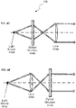
- FIG. 3A is a block diagram that illustrates a specially designed Structure A with a step-like profile with four sections.
- the sections of the Structure A are characterized as having different optical path differences, L1 to L4, that introduce different amounts of delay into the optical beam, such as Optical Beam A from, e.g., a fiber end, which propagates through those sections.
- FIG. 3B shows another block diagram that illustrates a specifically designed Structure B with a step profile that introduces similar delays as in FIG. 3A but with a modified spatial arrangement of the step profile of Structure B.
- FIG. 3A is a block diagram that illustrates a specially designed Structure A with a step-like profile with four sections.
- the sections of the Structure A are characterized as having different optical path differences, L1 to L4, that introduce different amounts of delay into the optical beam, such as Optical Beam A from, e.g., a fiber end, which propagates through those sections.
- FIG. 3B shows another block diagram that illustrates a specifically designed Structure B with
- FIGS. 3A and 3B illustrates a collimated Optical Beam B that is incident on Structure B.
- the structures that are shown in FIGS. 3A and 3B can be readily manufactured at a low cost.
- Other exemplary optical structures with different shapes and profiles, and comprising different materials, can be constructed to provide specific delays into the optical beam.
- the spectral bandwidth of the light source, ⁇ f is selected to be much wider than r . That is, ⁇ f >> r.
- an optical component such as a Fresnel lens introduces delays into different sections of the transmit aperture (i.e., the sub-apertures) such that the optical path difference, L, introduced in each section follows the following relationships: L ⁇ c / r and L >> c / ⁇ f, where c is the speed of light.
- the first relationship, L ⁇ c / r , or equivalently, L ⁇ c T S ensures that the spatial modulation is not impaired by mis-timing and also reduces intersymbol interference.
- the second relationship, L >> c / ⁇ f ensures that each delayed section of the beam is incoherent with other sections of the beam. That is, the optical path difference is selected to be much larger than the spatial extent of a symbol.
- N different delays are introduced into the optical beam.
- L Shift is the optical path difference introduced by each zone
- f is the focal length of the lens
- R is the radius of the last zone of the Fresnel lens as measured from the center of the lens.
- the receiver that receives the transmitted light in the far field detects the total energy of the incident beam, including light from each of the zones of the transmit aperture.
- the detected energy of at the receiver is the sum of energies from each zone, regardless of their phase differences. Because the received optical signals are not coherent, the noise due to atmospheric propagation is reduced in the aggregate signal. Increasing the number, N , of non-coherent signals produced at the transmitter and received at the receiver further improves the signal-to-noise ratio of the detected optical signal
- FIG. 4A through FIG. 4E show different examples of optical systems that include the disclosed optical components for introducing different amounts of delay in different sections of an optical beam.
- FIG. 4A illustrates a first lens 406a that is positioned to receive light from a light source 402a and to produce a collimated light beam that is incident on an optical structure 404a.
- the optical structure 404a introduces different amounts of delay in different sections of the optical beam.
- the optical structure 404a can, for example, be a plate structure such as any of the example structures shown in FIGS. 3A and 3B .
- the optical beam that exits the optical structure 404a is incident on a second lens 408a and subsequently on a third lens 410a, which produces a collimated output beam.
- the second lens 408a and third lens 410a form a telescope structure.
- FIG. 4B illustrates a lens 406b that is positioned to received light from a light source 402b.
- the collimated light that exits the lens 406b impinges upon an optical structure 404b that introduces different amounts of delay in different sections of the optical beam.
- the optical structure 404b can, for example, be a plate structure such as any of the example structures shown in FIGS. 3A and 3B .
- the optical beam produced by the light source 402c is received by an optical structure 404c that introduces different amounts of delay in different sections of the optical beam upon exit from the optical structure 404c.
- the optical structure 404c can, for example, be a Fresnel Lens.
- FIG. 4D shows another configuration in which light from a light source 402d is received at an optical structure 404d that introduces different amounts of delay in different sections of the optical beam.
- the optical structure 404d can, for example, be a Fresnel Lens.
- the light that exits the optical structure 404d is received by lens 406d, which produces a collimated output beam.
- the light from a light source 402e is received at a lens 406e and is subsequently incident on an optical structure 404e that introduces different amounts of delay in different sections of the optical beam.
- the optical structure 404e can, for example, be a Fresnel Lens.
- more than one optical structure can be placed within the optical transmitter to introduce delays.
- Such structures can produce delays in either a cumulative fashion (e.g., each structure produces a certain amount of delay that adds to the optical delay produced by other structure(s)) or separately (e.g., each structure operates on a different portion of the beam).
- FIG. 5 illustrates a set of operations that can be carried out to allow transmission of multiple beams in a free space optical communication system.
- a broad-spectrum light beam is generated.
- the intensity of the light beam is modulated to represent information to be conveyed through the system.
- the modulated light beam is received at an optical component that comprises a plurality of sections.
- the modulated light beam is allowed to propagate through the optical component.
- each section of the optical component that is illuminated by the light beam introduces a particular delay into a portion of the light beam that propagates through such section, and each particular delay introduced by a corresponding section of the optical component causes the portion of the light beam that exits the corresponding section to lack coherence with other portions of the light beam that exit other sections of the optical component.
- the output light beam is transmitted from the transmitter, or the transmit terminal, to a receive terminal through an aberrated medium such as the atmosphere having atmospheric turbulence.
- the received optical beam has varying amounts of delay that are incoherent with respect to one another, and thus can be combined using direct detection of the received light intensities.
- the light beam is received at a receive terminal and direct detection is performed to measure the optical intensity of the received light beam.
- the transmitted data is estimated from the measured intensity.
- the modulated light beam has a modulation rate, r , and an optical path difference associated with each section of the optical component is smaller than c/r, where c is the speed of light in vacuum.
- optical path difference is at least an order of magnitude smaller than c / r .
- an optical path difference associated with each section of the optical component is larger than c / ⁇ f , where c is the speed of light and ⁇ f is the spectral bandwidth of a broad spectrum light source that produces the modulated light beam.
- the optical path difference is at least two orders of magnitude larger than c / ⁇ f .
- the modulated light beam is one of an intensity modulated light beam.
- the modulated light beam has a modulation rate, r
- the modulated light beam is produced using a light source with a spectral bandwidth that is larger than r .
- the spectral bandwidth that is at least an order of magnitude larger than r .
- the optical component is a Fresnel lens with a plurality of circular zones, where each of the plurality of sections corresponds to one circular zone of the Fresnel lens.
- the optical component is a plate with a step-like spatial profile that includes a plurality of segments, and each of the plurality of sections corresponds to one segment of the plurality of segments of the plate.
- the operations of FIG. 5 further include providing a plurality of the portions of optical beam, subsequent to propagation through the multiple sections of the optical component, for transmission onto atmosphere.
Landscapes
- Physics & Mathematics (AREA)
- Electromagnetism (AREA)
- Engineering & Computer Science (AREA)
- Computer Networks & Wireless Communication (AREA)
- Signal Processing (AREA)
- Astronomy & Astrophysics (AREA)
- General Physics & Mathematics (AREA)
- Optical Communication System (AREA)
Claims (15)
- Ein optischer Sender zum Senden von Licht in einem optischen Freiraumkommunikationssystem, beinhaltend:eine Breitspektrumslichtquelle; undeine optische Komponente, die eine Vielzahl von Abschnitten umfasst und positioniert ist, um einen optischen Strahl zu empfangen, der von der Breitspektrumslichtquelle produziert wird, wobei:die Vielzahl von Abschnitten gebildet ist, um in Teilen des optischen Strahls, die auf die optische Komponente auftreffen, Unterschiede des optischen Wegs einzuführen, sodass jeder Abschnitt in einem entsprechenden Teil des optischen Strahls eine Verzögerung einführt, die sich von einer von anderen Abschnitten der optischen Komponente in anderen Teilen des optischen Strahls eingeführten Verzögerung unterscheidet, unddie von der Vielzahl von Abschnitten eingeführten Verzögerungen bewirken, dass jeder Teil des optischen Strahls, der auf einen entsprechenden Abschnitt der optischen Komponente auftrifft, über keine Kohärenz mit anderen Teilen des optischen Strahls, die auf andere Abschnitte der optischen Komponente auftreffen, verfügt,dadurch gekennzeichnet, dass die optische Komponente eine Fresnel-Linse mit einer Vielzahl kreisförmiger Zonen ist und jeder der Vielzahl von Abschnitten einer kreisförmigen Zone der Fresnel-Linse entspricht.
- Optischer Sender gemäß Anspruch 1, ferner beinhaltend einen Modulator, und wobei der von der optischen Komponente empfangene optische Strahl ein von dem Modulator modulierter optischer Strahl mit einer Modulationsrate r ist und jeder der Vielzahl der Abschnitte der optischen Komponente gebildet ist, um einen bestimmten Unterschied des optischen Wegs einzuführen, der signifikant kleiner als c/r ist, wobei c die Lichtgeschwindigkeit im Vakuum ist.
- Optischer Sender gemäß Anspruch 2, wobei jeder der Vielzahl der Abschnitte der optischen Komponente gebildet ist, um einen bestimmten Unterschied des optischen Wegs zu produzieren, der mehr als c/Δf beträgt, wobei c die Lichtgeschwindigkeit im Vakuum ist und Δf die spektrale Bandbreite der Breitspektrumslichtquelle ist.
- Optischer Sender gemäß einem der Ansprüche 1 bis 3, wobei der von der optischen Komponente empfangene optische Strahl einer von einem intensitätsmodulierten optischen Strahl ist und/oder
wobei der von der optischen Komponente empfangene optische Strahl ein modulierter optischer Strahl mit einer Modulationsrate r ist und wobei die Lichtquelle eine spektrale Bandbreite aufweist, die größer als r ist. - Optische Sender gemäß einem der Ansprüche 1 bis 4, wobei die Breitspektrumslichtquelle eines von Folgendem ist: eine Breitband-Laserdiode (LD), eine Superlumineszenzdiode (SLD), eine Leuchtdiode (LED) oder eine Quelle verstärkter spontaner Emission (ASE).
- Optischer Sender gemäß einem der Ansprüche 1 bis 5, wobei:die optische Komponente eine Platte mit einem stufenartigen räumlichen Profil ist, die eine Vielzahl von Segmenten umfasst, undjeder der Vielzahl von Abschnitten einem Segment der Vielzahl von Segmenten der Platte entspricht.
- Optischer Sender gemäß einem der Ansprüche 1 bis 6, wobei die Breitspektrumslichtquelle und die optische Komponente im Inneren von einem oder beiden von (a) einem unbemannten Luftfahrzeug oder (b) einer bodenbasierten Station platziert sind und die optische Komponente positioniert ist, um eine Vielzahl der Teile eines optischen Strahls nach der Ausbreitung durch die mehreren Abschnitte der optischen Komponente zum Senden in Atmosphäre bereitzustellen.
- Optischer Sender gemäß einem der Ansprüche 1 bis 7, wobei die optische Komponente an der Austrittsöffnung des optischen Senders positioniert ist.
- Ein Verfahren zum Produzieren mehrerer Strahlen zum Senden an einem optischen Freiraumkommunikationssystem, beinhaltend:Empfangen eines von einem Modulator modulierten Lichtstrahls an einer optischen Komponente, die eine Vielzahl von Abschnitten beinhaltet; undErmöglichen der Ausbreitung des modulierten Lichtstrahls durch die optische Komponente, wobei: jeder Abschnitt der optischen Komponente, der von dem Lichtstrahl beleuchtet wird, eine bestimmte Verzögerung in einem Teil des Lichtstrahls, der sich durch einen derartigen Abschnitt ausbreitet, einführt, undjede von einem entsprechenden Abschnitt der optischen Komponente eingeführte bestimmte Verzögerung bewirkt, dass der Teil des Lichtstrahls, der aus dem entsprechenden Abschnitt austritt, über keine Kohärenz mit anderen Teilen des Lichtstrahls, der aus anderen Abschnitten der optischen Komponente austritt, verfügt, dadurch gekennzeichnet, dass die optische Komponente eine Fresnel-Linse mit einer Vielzahl kreisförmiger Zonen ist und jeder der Vielzahl von Abschnitten einer kreisförmigen Zone der Fresnel-Linse entspricht.
- Verfahren gemäß Anspruch 9, wobei der modulierte Lichtstrahl eine Modulationsrate r aufweist und wobei ein Unterschied des optischen Wegs, der mit jedem Abschnitt assoziiert ist, signifikant kleiner als c/r ist, wobei c die Lichtgeschwindigkeit im Vakuum ist; und/oder
wobei der modulierte Lichtstrahl eine Modulationsrate r aufweist und wobei der modulierte Lichtstrahl unter Verwendung einer Lichtquelle mit einer spektralen Bandbreite, die größer als r ist, produziert wird. - Verfahren gemäß Anspruch 9 oder 10, wobei ein Unterschied des optischen Wegs, der mit jedem Abschnitt assoziiert ist, bei größer als cΔf ist, wobei c die Lichtgeschwindigkeit im Vakuum ist und Δf die spektrale Bandbreite einer Breitspektrumslichtquelle ist, die den modulierten Lichtstrahl produziert.
- Verfahren gemäß einem der Ansprüche 9 bis 11, wobei der modulierte Lichtstrahl einer von einem intensitätsmodulierten Lichtstrahl ist.
- Verfahren gemäß einem der Ansprüche 9 bis 12, wobei die optische Komponente eine Platte mit einem stufenartigen räumlichen Profil ist, die eine Vielzahl von Segmenten umfasst, und jeder der Vielzahl von Abschnitten einem Segment der Vielzahl von Segmenten der Platte entspricht.
- Verfahren gemäß einem der Ansprüche 9 bis 13, ferner beinhaltend das Senden einer Vielzahl der Teilen eines optischen Strahls durch Atmosphäre im Anschluss an die Ausbreitung durch die mehreren Abschnitte der optischen Komponente.
- Ein optisches Freiraumkommunikationssystem, beinhaltend:einen Sender gemäß den Ansprüchen 1 bis 8; undeinen Empfänger, der positioniert ist, um eine Vielzahl der Teile des optischen Strahls, der aus der optischen Komponente austritt und sich durch Atmosphäre ausbreitet, zu empfangen, wobei der Empfänger einen Photodetektor zum Abfühlen einer Intensität der empfangenen Teile des optischen Strahls umfasst.
Applications Claiming Priority (2)
| Application Number | Priority Date | Filing Date | Title |
|---|---|---|---|
| US14/984,093 US10038499B2 (en) | 2015-12-30 | 2015-12-30 | Intensity modulated direct detection broad optical-spectrum source communication |
| PCT/US2016/069033 WO2017117300A1 (en) | 2015-12-30 | 2016-12-28 | Intensity modulated direct detection broad optical-spectrum source communication |
Publications (3)
| Publication Number | Publication Date |
|---|---|
| EP3353910A1 EP3353910A1 (de) | 2018-08-01 |
| EP3353910A4 EP3353910A4 (de) | 2019-06-26 |
| EP3353910B1 true EP3353910B1 (de) | 2020-04-15 |
Family
ID=59225561
Family Applications (1)
| Application Number | Title | Priority Date | Filing Date |
|---|---|---|---|
| EP16882613.9A Active EP3353910B1 (de) | 2015-12-30 | 2016-12-28 | Kommunikation mit optischer breitspektrumsquelle mit intensitätsmodulierter direkterkennung |
Country Status (4)
| Country | Link |
|---|---|
| US (2) | US10038499B2 (de) |
| EP (1) | EP3353910B1 (de) |
| CN (1) | CN108476067B (de) |
| WO (1) | WO2017117300A1 (de) |
Families Citing this family (6)
| Publication number | Priority date | Publication date | Assignee | Title |
|---|---|---|---|---|
| US9866320B2 (en) | 2015-12-30 | 2018-01-09 | Facebook, Inc. | Intensity-modulated direct detection with multi-channel multi-beaming |
| US10305604B1 (en) * | 2017-12-28 | 2019-05-28 | Facebook, Inc. | Coherent aperture combining using machine learning |
| KR102781935B1 (ko) * | 2019-09-23 | 2025-03-19 | 삼성디스플레이 주식회사 | 백라이트 장치 및 이를 포함하는 3차원 영상 표시 장치 |
| CN118041447A (zh) | 2019-10-16 | 2024-05-14 | Wyss生物和神经工程中心 | 可植入系统的光传输 |
| CN111856766B (zh) * | 2020-07-31 | 2021-06-08 | 西安电子科技大学 | 抑制湍流效应的自聚焦涡旋光束产生方法 |
| CN114257302A (zh) * | 2021-12-07 | 2022-03-29 | 武汉邮电科学研究院有限公司 | 一种基于单个ase光源实现无线通信的方法及系统 |
Family Cites Families (30)
| Publication number | Priority date | Publication date | Assignee | Title |
|---|---|---|---|---|
| US4521075A (en) * | 1983-03-07 | 1985-06-04 | Obenschain Stephen P | Controllable spatial incoherence echelon for laser |
| US5121231A (en) | 1990-04-06 | 1992-06-09 | University Of Southern California | Incoherent/coherent multiplexed holographic recording for photonic interconnections and holographic optical elements |
| KR100258183B1 (ko) | 1997-09-08 | 2000-06-01 | 정선종 | 채널간 지연보상형 다파장 채널 투과 광필터 |
| US6731878B1 (en) | 2000-08-17 | 2004-05-04 | At&T Corp | Free space optical communication link with diversity |
| US6807375B2 (en) * | 2001-01-09 | 2004-10-19 | University Of Central Florida | Free-space optical communications with partially coherent beams |
| US20020126479A1 (en) | 2001-03-08 | 2002-09-12 | Ball Semiconductor, Inc. | High power incoherent light source with laser array |
| US7181097B2 (en) * | 2001-03-15 | 2007-02-20 | Massachusetts Institute Of Technology | Methods of achieving optimal communications performance |
| JP2004112336A (ja) * | 2002-09-18 | 2004-04-08 | Pioneer Electronic Corp | 変調装置、送信装置及びコンピュータプログラム |
| JP2004279589A (ja) | 2003-03-13 | 2004-10-07 | Fujitsu Ltd | 多波長光源生成方法及びその装置 |
| US7079254B2 (en) * | 2003-03-26 | 2006-07-18 | Southwest Sciences Incorporated | Method and apparatus for imaging internal structures of transparent and translucent materials |
| US7277644B2 (en) | 2003-06-13 | 2007-10-02 | The Regents Of The University Of California | Fade-resistant forward error correction method for free-space optical communications systems |
| US20050196170A1 (en) | 2004-03-02 | 2005-09-08 | Winsor Robert S. | Method and apparatus for free space optical communication using incoherent light |
| WO2005119942A2 (en) | 2004-06-01 | 2005-12-15 | The Penn State Research Foundation | Optical wireless communications using ultra short light pulses and pulse shaping |
| EP1803307A1 (de) | 2004-10-12 | 2007-07-04 | JDS Uniphase Corporation | Systeme und verfahren zur optischen vermittlung zu farblosen ports und farbigen ports |
| US7970280B2 (en) | 2004-10-26 | 2011-06-28 | Infinera Corporation | Thermally-floating transmitter wavelength grid of signal channels in a WDM transmission system |
| JPWO2006095411A1 (ja) | 2005-03-08 | 2008-08-14 | 富士通株式会社 | 光空間通信方法、光送信装置、光受信装置、光空間通信システム |
| US7920794B1 (en) * | 2007-01-05 | 2011-04-05 | Lockheed Martin Corporation | Free space optical communication |
| CN101282175B (zh) * | 2008-05-16 | 2012-07-04 | 西安理工大学 | 基于垂直分层空时编码的自由空间mimo光通信系统 |
| US20090324243A1 (en) | 2008-06-30 | 2009-12-31 | Lucent Technologies Inc. | Scalable load-balanced interconnect switch based on an optical switch fabric having a bank of wavelength-selective switches |
| US20100053474A1 (en) | 2008-08-31 | 2010-03-04 | Hiromi Kamei | Systems and methods for eliminating laser light source scintillation in a projection television |
| JP5161176B2 (ja) * | 2008-09-26 | 2013-03-13 | 太陽誘電株式会社 | 可視光通信用送信機及び可視光通信システム |
| CN102714549A (zh) | 2009-09-17 | 2012-10-03 | 杜伊斯堡-埃森大学 | 用于收发光信号的发射机和接收机 |
| WO2011098982A1 (en) * | 2010-02-12 | 2011-08-18 | Grigory Gelikonov | Method and system for free-space optical communication with reduced scintillations |
| US9048950B2 (en) | 2010-07-07 | 2015-06-02 | LGS Innovations LLC | Multiple-input method and apparatus of free-space optical communication |
| US10033477B2 (en) | 2012-07-27 | 2018-07-24 | Hewlett Packard Enterprise Development Lp | Spatial multiplexing for optical transmission |
| CN102820923B (zh) * | 2012-08-17 | 2015-06-24 | 山东大学 | Mimo自由空间光通信中联合分集接收的发射光径选择方法 |
| KR20140075861A (ko) | 2012-12-05 | 2014-06-20 | 한국전자통신연구원 | 자유공간을 매체로 하는 광대역 무선 광 통신 시스템에서의 통신 장치 및 그 송수신 방법 |
| EP2838217A1 (de) | 2013-08-13 | 2015-02-18 | Alcatel Lucent | Optisches Kommunikationssystem mit optischen Paketen mit mehreren Wellenlängen |
| CN204906403U (zh) * | 2015-09-06 | 2015-12-23 | 中国计量学院 | 一种自由空间光通信双调制解调装置 |
| US9866320B2 (en) | 2015-12-30 | 2018-01-09 | Facebook, Inc. | Intensity-modulated direct detection with multi-channel multi-beaming |
-
2015
- 2015-12-30 US US14/984,093 patent/US10038499B2/en active Active
-
2016
- 2016-12-28 EP EP16882613.9A patent/EP3353910B1/de active Active
- 2016-12-28 WO PCT/US2016/069033 patent/WO2017117300A1/en not_active Ceased
- 2016-12-28 CN CN201680077618.5A patent/CN108476067B/zh not_active Expired - Fee Related
-
2018
- 2018-01-04 US US15/862,587 patent/US10320479B2/en active Active
Non-Patent Citations (1)
| Title |
|---|
| None * |
Also Published As
| Publication number | Publication date |
|---|---|
| US10320479B2 (en) | 2019-06-11 |
| US20170195057A1 (en) | 2017-07-06 |
| EP3353910A1 (de) | 2018-08-01 |
| US20180302160A1 (en) | 2018-10-18 |
| EP3353910A4 (de) | 2019-06-26 |
| CN108476067B (zh) | 2021-09-10 |
| US10038499B2 (en) | 2018-07-31 |
| CN108476067A (zh) | 2018-08-31 |
| WO2017117300A1 (en) | 2017-07-06 |
Similar Documents
| Publication | Publication Date | Title |
|---|---|---|
| EP3353910B1 (de) | Kommunikation mit optischer breitspektrumsquelle mit intensitätsmodulierter direkterkennung | |
| Kaushal et al. | Free space optical communication | |
| US9794903B2 (en) | Synchronization of distributed nodes | |
| US11750296B2 (en) | Optical communication link ranging | |
| Wen et al. | Optical integrated sensing and communication: Architectures, potentials and challenges | |
| CN106464330B (zh) | 建立毫米连接的方法和设备 | |
| US11381314B2 (en) | Free space optical communication systems and methods for QOS control | |
| Kiviranta et al. | 5G radar: Scenarios, numerology and simulations | |
| Tiwari et al. | A review on inter-satellite links free space optical communication | |
| CN106033985A (zh) | 一种星地通信系统和方法 | |
| KR102738820B1 (ko) | 무선 통신 시스템에서 고주파 대역의 상향링크 신호를 송수신하는 방법 및 이를 위한 장치 | |
| Kaushal et al. | Overview of wireless optical communication systems | |
| Mulholland et al. | Intersatellite laser crosslinks | |
| US11581947B2 (en) | Underwater communications system having selectable beam and associated methods | |
| Sharma et al. | A review on inter-satellite optical wireless communication | |
| Kumari et al. | System analysis for optical inter-satellite link with varied parameter and pre-amplification | |
| US10637576B2 (en) | Transmitter for an optical free-beam communication system | |
| Kumari et al. | Performance optimization of return-to-zero DPSK modulation in inter-satellite optical wireless communication | |
| Kaur et al. | Review on Inter-satellite Optical Wireless Communication system. | |
| Alluru et al. | An optical payload for cubesats | |
| Erturk et al. | Potential future aviation communication technologies | |
| Dudley et al. | Ultrabroadband wireless–optical transmission links using axial slot leaky feeders and optical fiber for underground transport topologies | |
| Verma et al. | Performance Investigation of WDM based hybrid RF-FSO Link with unmanned aerial vehicles based optical relays | |
| Kanno | High bitrate mm-wave links using RoF technologies and its non-telecom application | |
| RU2817401C1 (ru) | Система радиосвязи с воздушными объектами |
Legal Events
| Date | Code | Title | Description |
|---|---|---|---|
| STAA | Information on the status of an ep patent application or granted ep patent |
Free format text: STATUS: THE INTERNATIONAL PUBLICATION HAS BEEN MADE |
|
| PUAI | Public reference made under article 153(3) epc to a published international application that has entered the european phase |
Free format text: ORIGINAL CODE: 0009012 |
|
| STAA | Information on the status of an ep patent application or granted ep patent |
Free format text: STATUS: REQUEST FOR EXAMINATION WAS MADE |
|
| 17P | Request for examination filed |
Effective date: 20180427 |
|
| AK | Designated contracting states |
Kind code of ref document: A1 Designated state(s): AL AT BE BG CH CY CZ DE DK EE ES FI FR GB GR HR HU IE IS IT LI LT LU LV MC MK MT NL NO PL PT RO RS SE SI SK SM TR |
|
| AX | Request for extension of the european patent |
Extension state: BA ME |
|
| DAV | Request for validation of the european patent (deleted) | ||
| DAX | Request for extension of the european patent (deleted) | ||
| A4 | Supplementary search report drawn up and despatched |
Effective date: 20190524 |
|
| RIC1 | Information provided on ipc code assigned before grant |
Ipc: H04B 10/118 20130101ALI20190520BHEP Ipc: H04B 10/112 20130101AFI20190520BHEP Ipc: H04B 10/54 20130101ALI20190520BHEP |
|
| REG | Reference to a national code |
Ref country code: DE Ref legal event code: R079 Ref document number: 602016034301 Country of ref document: DE Free format text: PREVIOUS MAIN CLASS: H04B0010500000 Ipc: H04B0010112000 |
|
| GRAP | Despatch of communication of intention to grant a patent |
Free format text: ORIGINAL CODE: EPIDOSNIGR1 |
|
| STAA | Information on the status of an ep patent application or granted ep patent |
Free format text: STATUS: GRANT OF PATENT IS INTENDED |
|
| RIC1 | Information provided on ipc code assigned before grant |
Ipc: H04B 10/112 20130101AFI20191011BHEP Ipc: H04B 10/118 20130101ALI20191011BHEP Ipc: H04B 10/54 20130101ALI20191011BHEP |
|
| INTG | Intention to grant announced |
Effective date: 20191107 |
|
| GRAS | Grant fee paid |
Free format text: ORIGINAL CODE: EPIDOSNIGR3 |
|
| GRAA | (expected) grant |
Free format text: ORIGINAL CODE: 0009210 |
|
| STAA | Information on the status of an ep patent application or granted ep patent |
Free format text: STATUS: THE PATENT HAS BEEN GRANTED |
|
| AK | Designated contracting states |
Kind code of ref document: B1 Designated state(s): AL AT BE BG CH CY CZ DE DK EE ES FI FR GB GR HR HU IE IS IT LI LT LU LV MC MK MT NL NO PL PT RO RS SE SI SK SM TR |
|
| REG | Reference to a national code |
Ref country code: CH Ref legal event code: EP |
|
| REG | Reference to a national code |
Ref country code: DE Ref legal event code: R096 Ref document number: 602016034301 Country of ref document: DE |
|
| REG | Reference to a national code |
Ref country code: IE Ref legal event code: FG4D |
|
| REG | Reference to a national code |
Ref country code: AT Ref legal event code: REF Ref document number: 1258529 Country of ref document: AT Kind code of ref document: T Effective date: 20200515 |
|
| REG | Reference to a national code |
Ref country code: NL Ref legal event code: MP Effective date: 20200415 |
|
| REG | Reference to a national code |
Ref country code: LT Ref legal event code: MG4D |
|
| PG25 | Lapsed in a contracting state [announced via postgrant information from national office to epo] |
Ref country code: FI Free format text: LAPSE BECAUSE OF FAILURE TO SUBMIT A TRANSLATION OF THE DESCRIPTION OR TO PAY THE FEE WITHIN THE PRESCRIBED TIME-LIMIT Effective date: 20200415 Ref country code: NO Free format text: LAPSE BECAUSE OF FAILURE TO SUBMIT A TRANSLATION OF THE DESCRIPTION OR TO PAY THE FEE WITHIN THE PRESCRIBED TIME-LIMIT Effective date: 20200715 Ref country code: GR Free format text: LAPSE BECAUSE OF FAILURE TO SUBMIT A TRANSLATION OF THE DESCRIPTION OR TO PAY THE FEE WITHIN THE PRESCRIBED TIME-LIMIT Effective date: 20200716 Ref country code: IS Free format text: LAPSE BECAUSE OF FAILURE TO SUBMIT A TRANSLATION OF THE DESCRIPTION OR TO PAY THE FEE WITHIN THE PRESCRIBED TIME-LIMIT Effective date: 20200815 Ref country code: PT Free format text: LAPSE BECAUSE OF FAILURE TO SUBMIT A TRANSLATION OF THE DESCRIPTION OR TO PAY THE FEE WITHIN THE PRESCRIBED TIME-LIMIT Effective date: 20200817 Ref country code: LT Free format text: LAPSE BECAUSE OF FAILURE TO SUBMIT A TRANSLATION OF THE DESCRIPTION OR TO PAY THE FEE WITHIN THE PRESCRIBED TIME-LIMIT Effective date: 20200415 Ref country code: SE Free format text: LAPSE BECAUSE OF FAILURE TO SUBMIT A TRANSLATION OF THE DESCRIPTION OR TO PAY THE FEE WITHIN THE PRESCRIBED TIME-LIMIT Effective date: 20200415 Ref country code: NL Free format text: LAPSE BECAUSE OF FAILURE TO SUBMIT A TRANSLATION OF THE DESCRIPTION OR TO PAY THE FEE WITHIN THE PRESCRIBED TIME-LIMIT Effective date: 20200415 |
|
| REG | Reference to a national code |
Ref country code: AT Ref legal event code: MK05 Ref document number: 1258529 Country of ref document: AT Kind code of ref document: T Effective date: 20200415 |
|
| PG25 | Lapsed in a contracting state [announced via postgrant information from national office to epo] |
Ref country code: RS Free format text: LAPSE BECAUSE OF FAILURE TO SUBMIT A TRANSLATION OF THE DESCRIPTION OR TO PAY THE FEE WITHIN THE PRESCRIBED TIME-LIMIT Effective date: 20200415 Ref country code: BG Free format text: LAPSE BECAUSE OF FAILURE TO SUBMIT A TRANSLATION OF THE DESCRIPTION OR TO PAY THE FEE WITHIN THE PRESCRIBED TIME-LIMIT Effective date: 20200715 Ref country code: HR Free format text: LAPSE BECAUSE OF FAILURE TO SUBMIT A TRANSLATION OF THE DESCRIPTION OR TO PAY THE FEE WITHIN THE PRESCRIBED TIME-LIMIT Effective date: 20200415 Ref country code: LV Free format text: LAPSE BECAUSE OF FAILURE TO SUBMIT A TRANSLATION OF THE DESCRIPTION OR TO PAY THE FEE WITHIN THE PRESCRIBED TIME-LIMIT Effective date: 20200415 |
|
| PG25 | Lapsed in a contracting state [announced via postgrant information from national office to epo] |
Ref country code: AL Free format text: LAPSE BECAUSE OF FAILURE TO SUBMIT A TRANSLATION OF THE DESCRIPTION OR TO PAY THE FEE WITHIN THE PRESCRIBED TIME-LIMIT Effective date: 20200415 |
|
| REG | Reference to a national code |
Ref country code: DE Ref legal event code: R097 Ref document number: 602016034301 Country of ref document: DE |
|
| PG25 | Lapsed in a contracting state [announced via postgrant information from national office to epo] |
Ref country code: SM Free format text: LAPSE BECAUSE OF FAILURE TO SUBMIT A TRANSLATION OF THE DESCRIPTION OR TO PAY THE FEE WITHIN THE PRESCRIBED TIME-LIMIT Effective date: 20200415 Ref country code: EE Free format text: LAPSE BECAUSE OF FAILURE TO SUBMIT A TRANSLATION OF THE DESCRIPTION OR TO PAY THE FEE WITHIN THE PRESCRIBED TIME-LIMIT Effective date: 20200415 Ref country code: DK Free format text: LAPSE BECAUSE OF FAILURE TO SUBMIT A TRANSLATION OF THE DESCRIPTION OR TO PAY THE FEE WITHIN THE PRESCRIBED TIME-LIMIT Effective date: 20200415 Ref country code: AT Free format text: LAPSE BECAUSE OF FAILURE TO SUBMIT A TRANSLATION OF THE DESCRIPTION OR TO PAY THE FEE WITHIN THE PRESCRIBED TIME-LIMIT Effective date: 20200415 Ref country code: ES Free format text: LAPSE BECAUSE OF FAILURE TO SUBMIT A TRANSLATION OF THE DESCRIPTION OR TO PAY THE FEE WITHIN THE PRESCRIBED TIME-LIMIT Effective date: 20200415 Ref country code: IT Free format text: LAPSE BECAUSE OF FAILURE TO SUBMIT A TRANSLATION OF THE DESCRIPTION OR TO PAY THE FEE WITHIN THE PRESCRIBED TIME-LIMIT Effective date: 20200415 Ref country code: RO Free format text: LAPSE BECAUSE OF FAILURE TO SUBMIT A TRANSLATION OF THE DESCRIPTION OR TO PAY THE FEE WITHIN THE PRESCRIBED TIME-LIMIT Effective date: 20200415 Ref country code: CZ Free format text: LAPSE BECAUSE OF FAILURE TO SUBMIT A TRANSLATION OF THE DESCRIPTION OR TO PAY THE FEE WITHIN THE PRESCRIBED TIME-LIMIT Effective date: 20200415 |
|
| PLBE | No opposition filed within time limit |
Free format text: ORIGINAL CODE: 0009261 |
|
| STAA | Information on the status of an ep patent application or granted ep patent |
Free format text: STATUS: NO OPPOSITION FILED WITHIN TIME LIMIT |
|
| PG25 | Lapsed in a contracting state [announced via postgrant information from national office to epo] |
Ref country code: PL Free format text: LAPSE BECAUSE OF FAILURE TO SUBMIT A TRANSLATION OF THE DESCRIPTION OR TO PAY THE FEE WITHIN THE PRESCRIBED TIME-LIMIT Effective date: 20200415 Ref country code: SK Free format text: LAPSE BECAUSE OF FAILURE TO SUBMIT A TRANSLATION OF THE DESCRIPTION OR TO PAY THE FEE WITHIN THE PRESCRIBED TIME-LIMIT Effective date: 20200415 |
|
| 26N | No opposition filed |
Effective date: 20210118 |
|
| PG25 | Lapsed in a contracting state [announced via postgrant information from national office to epo] |
Ref country code: SI Free format text: LAPSE BECAUSE OF FAILURE TO SUBMIT A TRANSLATION OF THE DESCRIPTION OR TO PAY THE FEE WITHIN THE PRESCRIBED TIME-LIMIT Effective date: 20200415 |
|
| REG | Reference to a national code |
Ref country code: CH Ref legal event code: PL |
|
| PG25 | Lapsed in a contracting state [announced via postgrant information from national office to epo] |
Ref country code: MC Free format text: LAPSE BECAUSE OF FAILURE TO SUBMIT A TRANSLATION OF THE DESCRIPTION OR TO PAY THE FEE WITHIN THE PRESCRIBED TIME-LIMIT Effective date: 20200415 |
|
| REG | Reference to a national code |
Ref country code: BE Ref legal event code: MM Effective date: 20201231 |
|
| PG25 | Lapsed in a contracting state [announced via postgrant information from national office to epo] |
Ref country code: IE Free format text: LAPSE BECAUSE OF NON-PAYMENT OF DUE FEES Effective date: 20201228 Ref country code: FR Free format text: LAPSE BECAUSE OF NON-PAYMENT OF DUE FEES Effective date: 20201231 Ref country code: LU Free format text: LAPSE BECAUSE OF NON-PAYMENT OF DUE FEES Effective date: 20201228 |
|
| PG25 | Lapsed in a contracting state [announced via postgrant information from national office to epo] |
Ref country code: CH Free format text: LAPSE BECAUSE OF NON-PAYMENT OF DUE FEES Effective date: 20201231 Ref country code: LI Free format text: LAPSE BECAUSE OF NON-PAYMENT OF DUE FEES Effective date: 20201231 |
|
| PG25 | Lapsed in a contracting state [announced via postgrant information from national office to epo] |
Ref country code: TR Free format text: LAPSE BECAUSE OF FAILURE TO SUBMIT A TRANSLATION OF THE DESCRIPTION OR TO PAY THE FEE WITHIN THE PRESCRIBED TIME-LIMIT Effective date: 20200415 Ref country code: MT Free format text: LAPSE BECAUSE OF FAILURE TO SUBMIT A TRANSLATION OF THE DESCRIPTION OR TO PAY THE FEE WITHIN THE PRESCRIBED TIME-LIMIT Effective date: 20200415 Ref country code: CY Free format text: LAPSE BECAUSE OF FAILURE TO SUBMIT A TRANSLATION OF THE DESCRIPTION OR TO PAY THE FEE WITHIN THE PRESCRIBED TIME-LIMIT Effective date: 20200415 |
|
| REG | Reference to a national code |
Ref country code: DE Ref legal event code: R081 Ref document number: 602016034301 Country of ref document: DE Owner name: META PLATFORMS, INC., US Free format text: FORMER OWNER: FACEBOOK, INC., MENLO PARK, CALIF., US Ref country code: DE Ref legal event code: R081 Ref document number: 602016034301 Country of ref document: DE Owner name: META PLATFORMS, INC., MENLO PARK, US Free format text: FORMER OWNER: FACEBOOK, INC., MENLO PARK, CALIF., US |
|
| PG25 | Lapsed in a contracting state [announced via postgrant information from national office to epo] |
Ref country code: MK Free format text: LAPSE BECAUSE OF FAILURE TO SUBMIT A TRANSLATION OF THE DESCRIPTION OR TO PAY THE FEE WITHIN THE PRESCRIBED TIME-LIMIT Effective date: 20200415 |
|
| PG25 | Lapsed in a contracting state [announced via postgrant information from national office to epo] |
Ref country code: BE Free format text: LAPSE BECAUSE OF NON-PAYMENT OF DUE FEES Effective date: 20201231 |
|
| P01 | Opt-out of the competence of the unified patent court (upc) registered |
Effective date: 20230524 |
|
| PGFP | Annual fee paid to national office [announced via postgrant information from national office to epo] |
Ref country code: GB Payment date: 20231229 Year of fee payment: 8 |
|
| PGFP | Annual fee paid to national office [announced via postgrant information from national office to epo] |
Ref country code: DE Payment date: 20231222 Year of fee payment: 8 |
|
| REG | Reference to a national code |
Ref country code: DE Ref legal event code: R081 Ref document number: 602016034301 Country of ref document: DE Owner name: META PLATFORMS, INC., MENLO PARK, US Free format text: FORMER OWNER: META PLATFORMS, INC., WILMINGTON, US |
|
| REG | Reference to a national code |
Ref country code: DE Ref legal event code: R119 Ref document number: 602016034301 Country of ref document: DE |
|
| GBPC | Gb: european patent ceased through non-payment of renewal fee |
Effective date: 20241228 |
|
| PG25 | Lapsed in a contracting state [announced via postgrant information from national office to epo] |
Ref country code: DE Free format text: LAPSE BECAUSE OF NON-PAYMENT OF DUE FEES Effective date: 20250701 |
|
| PG25 | Lapsed in a contracting state [announced via postgrant information from national office to epo] |
Ref country code: GB Free format text: LAPSE BECAUSE OF NON-PAYMENT OF DUE FEES Effective date: 20241228 |