EP3353855B1 - Deployable structure for use in establishing a reflectarray antenna - Google Patents
Deployable structure for use in establishing a reflectarray antenna Download PDFInfo
- Publication number
- EP3353855B1 EP3353855B1 EP16849901.0A EP16849901A EP3353855B1 EP 3353855 B1 EP3353855 B1 EP 3353855B1 EP 16849901 A EP16849901 A EP 16849901A EP 3353855 B1 EP3353855 B1 EP 3353855B1
- Authority
- EP
- European Patent Office
- Prior art keywords
- pantograph
- reflectarray
- endless
- tape
- deployed
- Prior art date
- Legal status (The legal status is an assumption and is not a legal conclusion. Google has not performed a legal analysis and makes no representation as to the accuracy of the status listed.)
- Active
Links
- 230000007246 mechanism Effects 0.000 claims description 29
- 230000007704 transition Effects 0.000 claims description 26
- 239000012528 membrane Substances 0.000 claims description 21
- 238000005381 potential energy Methods 0.000 claims description 16
- WYTGDNHDOZPMIW-RCBQFDQVSA-N alstonine Natural products C1=CC2=C3C=CC=CC3=NC2=C2N1C[C@H]1[C@H](C)OC=C(C(=O)OC)[C@H]1C2 WYTGDNHDOZPMIW-RCBQFDQVSA-N 0.000 claims description 5
- 239000002131 composite material Substances 0.000 description 16
- 238000013461 design Methods 0.000 description 5
- 230000008859 change Effects 0.000 description 3
- 238000013459 approach Methods 0.000 description 2
- 238000004891 communication Methods 0.000 description 2
- 238000003384 imaging method Methods 0.000 description 2
- 230000006978 adaptation Effects 0.000 description 1
- 230000003466 anti-cipated effect Effects 0.000 description 1
- 239000000470 constituent Substances 0.000 description 1
- 230000001186 cumulative effect Effects 0.000 description 1
- 230000007423 decrease Effects 0.000 description 1
- 238000012986 modification Methods 0.000 description 1
- 230000004048 modification Effects 0.000 description 1
- 230000005855 radiation Effects 0.000 description 1
- 125000006850 spacer group Chemical group 0.000 description 1
- 238000013519 translation Methods 0.000 description 1
Images


Classifications
-
- H—ELECTRICITY
- H01—ELECTRIC ELEMENTS
- H01Q—ANTENNAS, i.e. RADIO AERIALS
- H01Q15/00—Devices for reflection, refraction, diffraction or polarisation of waves radiated from an antenna, e.g. quasi-optical devices
- H01Q15/14—Reflecting surfaces; Equivalent structures
-
- B—PERFORMING OPERATIONS; TRANSPORTING
- B64—AIRCRAFT; AVIATION; COSMONAUTICS
- B64G—COSMONAUTICS; VEHICLES OR EQUIPMENT THEREFOR
- B64G1/00—Cosmonautic vehicles
- B64G1/22—Parts of, or equipment specially adapted for fitting in or to, cosmonautic vehicles
- B64G1/222—Parts of, or equipment specially adapted for fitting in or to, cosmonautic vehicles for deploying structures between a stowed and deployed state
-
- B—PERFORMING OPERATIONS; TRANSPORTING
- B64—AIRCRAFT; AVIATION; COSMONAUTICS
- B64G—COSMONAUTICS; VEHICLES OR EQUIPMENT THEREFOR
- B64G1/00—Cosmonautic vehicles
- B64G1/22—Parts of, or equipment specially adapted for fitting in or to, cosmonautic vehicles
- B64G1/40—Arrangements or adaptations of propulsion systems
- B64G1/407—Solar sailing
-
- B—PERFORMING OPERATIONS; TRANSPORTING
- B64—AIRCRAFT; AVIATION; COSMONAUTICS
- B64G—COSMONAUTICS; VEHICLES OR EQUIPMENT THEREFOR
- B64G1/00—Cosmonautic vehicles
- B64G1/22—Parts of, or equipment specially adapted for fitting in or to, cosmonautic vehicles
- B64G1/42—Arrangements or adaptations of power supply systems
- B64G1/44—Arrangements or adaptations of power supply systems using radiation, e.g. deployable solar arrays
- B64G1/443—Photovoltaic cell arrays
-
- B—PERFORMING OPERATIONS; TRANSPORTING
- B64—AIRCRAFT; AVIATION; COSMONAUTICS
- B64G—COSMONAUTICS; VEHICLES OR EQUIPMENT THEREFOR
- B64G1/00—Cosmonautic vehicles
- B64G1/22—Parts of, or equipment specially adapted for fitting in or to, cosmonautic vehicles
- B64G1/66—Arrangements or adaptations of apparatus or instruments, not otherwise provided for
-
- H—ELECTRICITY
- H01—ELECTRIC ELEMENTS
- H01Q—ANTENNAS, i.e. RADIO AERIALS
- H01Q1/00—Details of, or arrangements associated with, antennas
- H01Q1/08—Means for collapsing antennas or parts thereof
-
- H—ELECTRICITY
- H01—ELECTRIC ELEMENTS
- H01Q—ANTENNAS, i.e. RADIO AERIALS
- H01Q1/00—Details of, or arrangements associated with, antennas
- H01Q1/12—Supports; Mounting means
- H01Q1/1235—Collapsible supports; Means for erecting a rigid antenna
-
- H—ELECTRICITY
- H01—ELECTRIC ELEMENTS
- H01Q—ANTENNAS, i.e. RADIO AERIALS
- H01Q1/00—Details of, or arrangements associated with, antennas
- H01Q1/27—Adaptation for use in or on movable bodies
- H01Q1/28—Adaptation for use in or on aircraft, missiles, satellites, or balloons
-
- H—ELECTRICITY
- H01—ELECTRIC ELEMENTS
- H01Q—ANTENNAS, i.e. RADIO AERIALS
- H01Q1/00—Details of, or arrangements associated with, antennas
- H01Q1/27—Adaptation for use in or on movable bodies
- H01Q1/28—Adaptation for use in or on aircraft, missiles, satellites, or balloons
- H01Q1/288—Satellite antennas
-
- H—ELECTRICITY
- H01—ELECTRIC ELEMENTS
- H01Q—ANTENNAS, i.e. RADIO AERIALS
- H01Q15/00—Devices for reflection, refraction, diffraction or polarisation of waves radiated from an antenna, e.g. quasi-optical devices
- H01Q15/14—Reflecting surfaces; Equivalent structures
- H01Q15/16—Reflecting surfaces; Equivalent structures curved in two dimensions, e.g. paraboloidal
- H01Q15/161—Collapsible reflectors
-
- H—ELECTRICITY
- H01—ELECTRIC ELEMENTS
- H01Q—ANTENNAS, i.e. RADIO AERIALS
- H01Q3/00—Arrangements for changing or varying the orientation or the shape of the directional pattern of the waves radiated from an antenna or antenna system
- H01Q3/44—Arrangements for changing or varying the orientation or the shape of the directional pattern of the waves radiated from an antenna or antenna system varying the electric or magnetic characteristics of reflecting, refracting, or diffracting devices associated with the radiating element
- H01Q3/46—Active lenses or reflecting arrays
Definitions
- the endless pantograph comprises two sets of linear sub-pantographs.
- the first set of linear sub-pantographs includes three or more linear sub-pantographs that define the edges of a polygon in the undeployed and deployed states.
- the second set of linear sub-pantographs comprises the same number of linear sub-pantographs as the first set of linear sub-pantographs and also define the edges of a plane polygon in the undeployed and deployed states.
- the second end of each of the tapes is operatively connected to or adjacent to a feed antenna of the reflectarray antenna.
- the three tapes contribute to the positioning of the deployed endless pantograph and the deployed reflectarray relative to the feed antenna in a reflectarray antenna.
- the deployed tapes and the deployed endless pantograph substantially define a pyramidic or conic structure.
- at least two of the tapes are of different lengths.
- the deployable structure when fully deployed, establishes the reflectarray and the feed antenna in a configuration known as a reflectarray antenna with an offset feed, i.e., the boresight of the feed antenna is not parallel to a line perpendicular to the deployed reflectarray.
- a reflectarray antenna comprising a deployable structure 20 for use in establishing the reflectarray antenna (hereinafter referred to as "the deployable structure 20") is described.
- the deployable structure 20 conforms to a design specification which requires the deployable structure 20, in the undeployed state, to fit within a volume that is 20 cm x 20 cm x 25 cm. Additional, the deployable structure 20 is required to have a mass of no more than 4 kg. Although the deployable structure 20 conforms to the this design specification, it should be appreciated that adaptation to other form factors and mass requirements is feasible.
- a spring structure is located at each of multiple pivots points of the endless pantograph 52.
- the spring structure 90 is associated with a pivot structure 92 that is used to establish a center pivot point between the pair of crossing legs or links 150A, 150B of an endless pantograph.
- the pivot structure 92 includes a first hole 98A associated with cross leg 150A, a second hole 98B associated with crossing leg 150B, a nut 100, and screw 102 that extends through each of the holes and engages the nut to establish a pivot connection between the crossing legs 150A, 150B.
- the nut 100, secrew 102 and holes 98A, 98B implement a full floating axle structure.
Description
- The invention relates to a reflectarray antenna comprising a deployable structure for use in establishing the reflectarray antenna.
- In applications requiring a high-gain antenna, there are at least three types of antennas that are typically employed, namely, a parabolic antenna, phased-array antenna, and a reflectarray antenna. The basic parabolic antenna includes a parabolic shaped reflector and a feed antenna located at the focus of the paraboloid and directed towards the reflector. The phased-array antenna includes multiple antennas with a feed network that provides a common signal to each of the antennas but with the relative phase of the common signal being fed to each of the antennas established such that the collective radiation pattern produced by the array of antennas is reinforced in one direction and suppressed in other directions, i.e., the beam is highly directional. In many applications, the phased-array antenna is preferred to the parabolic antenna because a phased-array antenna can be realized with a lower height profile relative to the parabolic antenna. However, the phased-array antenna typically requires a complicated and/or expensive feed network and amplifier structures. The basic reflectarray antenna includes a reflectarray that is flat or somewhat curved and a feed antenna directed towards the reflectarray. The reflectarray includes an array of radiating elements that each receive a signal from the feed antenna and reradiate the signal. Each of the radiating elements has a phase delay such that the collective reradiated signal produced by the array of radiating elements is in a desired direction. Importantly, the radiating elements are fed by the feed antenna. As such, relative to the phased-arrayed antenna, the reflectarray avoids the need for a feed network to provide a signal to each of the radiating elements.
- An application that frequently requires a high-gain antenna is a space-related application in which the antenna is associated with a spacecraft, e.g., a communication or radar imaging satellite. Such space-related applications typically impose an additional requirement of deployability on the design of a high-gain antenna, i.e., the antenna needs to be able to transition from a stowed/undeployed state in which the antenna is inoperable or marginally operable to unstowed/deployed state in which the antenna is operable. As such, the high-gain antenna in these applications is coupled with a deployment mechanism that is used to transition the antenna from the stowed/undeployed state to the unstowed/deployed state. Characteristic of many space-related applications for such antennas is that the antenna and deployment mechanism occupy a small volume in the undeployed state relative to the volume occupied by the antenna and deployment mechanism in the deployed state.
- One approach for realizing a deployable high-gain antenna suitable for use on a spacecraft is a parabolic antenna structure that includes a wire mesh reflector, a feed antenna, and a deployment mechanism. The deployment mechanism operates to transition: (a) the wire mesh reflector from a stowed state in which the reflector is folded to an unstowed state in which the reflector is supported in a paraboloid-like shape by a frame associated with the deployment mechanism and (b) the wire mesh reflector and the feed antenna from an inoperable stowed state in which the wire mesh reflector and feed antenna are not operably positioned relative to one another to an unstowed state in which the wire mesh reflector and feed antenna are operatively positioned relative to one another. Characteristic of such deployable parabolic antenna structures is a high part count and the need for a relatively large volume to accommodate the stowed wire mesh reflector, feed antenna, and deployment mechanism.
- A second approach for realizing a deployable high-gain antenna suitable for use on a spacecraft is a reflectarray antenna structure that includes a two-layer reflectarray membrane, a feed antenna, and an inflatable deployment mechanism. The inflatable deployment mechanism operates to transition: (a) the reflectarray membrane from a stowed state in which the membrane is folded to an unstowed state in which the inflated deployment mechanism forms a frame that is used in tensioning the reflectarray membrane into a flat shape, similar to trampoline and (b) the reflectarray membrane and the feed antenna from an inoperable stowed state in which the reflectarray membrane and feed antenna are not operably positioned with respect to one another to an unstowed state in which the reflectarray membrane and the feed antenna are operably positioned relative to one another. Characteristic of such a deployable reflectarray are difficulties in understanding the deployment kinematics and reliability challenges, particularly in space-based applications.
-
US 6323827B1 TRW 27 November 2001 describes a deployable structure for use in establishing an antenna comprising a base; an antenna comprising a feed antenna and a flexible electrical element; wherein the flexible electrical element is folded in an undeployed state; wherein the flexible electrical element is unfolded in a deployed state relative to the undeployed state; and a deployment mechanism for transitioning the flexible electrical element from the undeployed state towards a deployed state; wherein the deployment mechanism includes an endless structure forming a closed loop, defining a perimeter that has a first length in the undeployed state and a second length that is greater than the first length when the endless structure transitions from the undeployed state towards a deployed state; and operatively engaged to the flexible electrical element; and an energy providing device for use in transitioning the endless structure from the undeployed state towards the deployed state; wherein, when the endless structure transitions from the undeployed state towards the deployed state, the flexible electrical element transitions from being folded in the undeployed state towards being unfolded. TRW is designed to establish a parabolic reflector antenna and proposes a perimeter truss structure which requires extension spars to support the reflective surface in the desired parabolic shape. TRW also teaches an energy providing device in the form of inflatable masts to carry the perimeter truss structure away from the base. -
US 2015/060605 EUROPEAN SPACE AGENCY 5 March 2015 describes a mechanical support ring structure that can be deployed andUS 2010/031525 THALES 11 February 2010 describes a deployable measuring tape that can serve as an energy providing device for space applications. - A reflectarray antenna comprising a deployable structure is defined in the appended claims. One such application for such a deployable structure is as part of a space vehicle, (e.g., a communication or radar imaging satellite) in which elements of the structure typically need to conform to a compact or dimensionally contained volume for at least a portion of the launch of the space vehicle and then be deployed from the compact or dimensionally constrained space so as to facilitate the establishment of a reflectarray antenna structure that typically occupies a considerably greater volume.
- In one embodiment of the reflectarray antenna, the endless pantograph has polygonal shape with at least three sides. Comprising the endless pantograph are linear sub-pantographs (i.e., pantographs that form the endless pantograph and extend in a substantially straight line when transitioning between the undeployed and deployed states) associated with each side of the polygonal shape and vertex structures that each extend between an end of one of the sub-pantographs and the end of the immediately adjacent sub-pantograph. In both the undeployed and deployed states, the sub-pantographs and vertex structures define a plane polygon with the linear sub-pantographs defining the edges of the polygon and the vertex structures defining the vertices of the polygon. In the undeployed state, the sub-pantographs define an undeployed perimeter with a first length. In a deployed state, the sub-pantographs define a deployed perimeter with a second length that is greater than the first length.
- In another embodiment of the reflectarray antenna, the endless pantograph comprises two sets of linear sub-pantographs. The first set of linear sub-pantographs includes three or more linear sub-pantographs that define the edges of a polygon in the undeployed and deployed states. The second set of linear sub-pantographs comprises the same number of linear sub-pantographs as the first set of linear sub-pantographs and also define the edges of a plane polygon in the undeployed and deployed states. The second set of sub-pantographs is located within the first set of sub-pantographs and oriented such that each of the linear sub-pantographs of the second set of sub-pantographs is disposed adjacent to a linear sub-pantograph of the first set of linear sub-pantographs of substantially the same length. As such, each linear sub-pantograph of the first set of linear sub-pantographs corresponds to one of the linear sub-pantographs of the second set of linear sub-pantographs. Each of the linear sub-pantographs of the first set of linear sub-pantographs is pivotally connected to the corresponding linear sub-pantograph of the second set of linear sub-pantographs (i.e., the corresponding linear sub-pantographs form a stacked linear sub-pantograph in which the constituent linear sub-pantographs lie in different planes). Further, the two sub-pantographs that form a stacked linear sub-pantograph are offset, i.e. the center or mid-leg pivot points are not collinear when the sub-pantographs are in an undeployed state. An offset of 180° provides the greatest increase in stiffness relative to a polygonal endless pantograph with sides formed by single sub-pantographs. However, other offsets are feasible. The two sets of linear sub-pantographs can be characterized as a plurality of composite stacked linear sub-pantographs with each composite stacked linear sub-pantograph having two linear sub-pantographs that are pivotally connected, lie in different planes, and are offset relative to one another. The endless pantograph also includes vertex structures that each extend between an end of a composite stacked linear sub-pantograph and the end of an adjacent composite stacked linear sub-pantograph. The endless pantograph structure with two sets of composite stacked linear sub-pantographs has an undeployed perimeter length that that is only slightly greater than the perimeter length of a comparable endless pantograph with sides formed by a single set of linear sub-pantographs (i.e., an endless pantograph with a single set of linear sub-pantographs that substantially has the same perimeter length when fully deployed as the endless pantograph structure with two sets of composite stacked linear sub-pantographs when fully deployed).
- In yet another embodiment of the reflectarray antenna, the endless pantograph comprises at least three composite linear sub-pantographs with each of the at least three composite linear sub-pantographs having a first linear pantograph that is interlaced with, pivotally connected to, and offset relative to a second linear pantograph (i.e., an interlaced linear pantograph in which the two pantographs lie in the same plane). An offset of 180° provides the greatest increase in stiffness relative to endless pantograph with sides formed by a single set of linear sub-pantographs. However, other offsets are feasible. A vertex structure extends between each end of a composite linear sub-pantograph and the end of an adjacent composite linear sub-pantograph. In this embodiment, the composite linear sub-pantographs that form each side of the endless pantograph can be characterized as composite interlaced linear sub-pantographs. The endless pantograph structure with composite linear sub-pantographs that each employ two interlaced linear sub-pantographs has an undeployed perimeter length that is greater than the perimeter length of a comparable endless pantograph with composite linear sub-pantographs that each employ stacked sub-pantographs (i.e., an endless pantograph with stacked linear sub-pantographs that substantially has the same perimeter length as the endless pantograph with interlaced linear sub-pantographs when fully deployed).
- While endless pantographs with polygonal shapes have certain desirable properties, an endless pantograph that is circular is also feasible and perhaps desirable in certain applications. Further, endless circular pantographs that are stacked or interlaced are also feasible.
- Yet another embodiment of the reflectarray antenna employs a limiter to limit the extent to which the endless pantograph is deployed. In one embodiment, the limiter includes a plurality of pins with each pin associated with a first leg of the endless pantograph and adapted to engage a second leg of the endless pantograph to which the first leg is pivotally attached in a manner that prevents relative rotation between the first and second legs once a desired angle between the first and second legs is reached during deployment. In a particular embodiment, a pin is associated with the two pivot joints located at the ends of each leg comprising the endless pantograph. The use of these pins, at least in endless pantographs with polygonal shapes, serves to limit the deployment of the endless pantograph, distribute the load, and reduce bowing in the deployed linear sub-pantographs (particularly when relatively long sub-pantographs are employed).
- In a particular embodiment of the reflectarray antenna, the energy providing device includes one or more springs that provide the energy for transitioning the endless pantograph and the flexible reflectarray from the undeployed state towards the deployed state. In a particular embodiment, the energy providing device comprises a spring associated with each pivot connection between the legs that form the endless pantograph. When the endless pantograph is in the undeployed state, the springs cumulatively store sufficient potential energy to transition the endless pantograph from the undeployed state to the deployed state. In the regard, when the restraint on the endless pantograph that maintains the endless pantograph in the deployed state is removed or reduced, the springs cause the legs that comprise the endless pantograph to rotate relative to one another and thereby transition the pantograph from the undeployed state towards the deployed state. Once the endless pantograph is in the deployed state, the springs store less potential energy than in the undeployed state but sufficient potential energy to maintain the endless pantograph in the deployed state based on the forces the deployed pantograph and reflectarray are reasonably expected to encounter in the relevant application. It should also be appreciated that by the use of multiple springs and the use of the multiple springs to store more potential energy than is needed to deploy and maintain the deployment of the endless pantograph and flexible reflectarray the failure of one or more springs can be accommodated.
- In another embodiment of the reflectarray antenna, the deployment mechanism includes a deployable tape structure for establishing a spatial relationship between the flexible reflectarray and another component of a reflectarray antenna. For instance, the deployable tape structure can be used in establishing the position of a feed antenna, subreflector, or reflectarray subreflector relative to the flexible reflectarray. In a particular embodiment, the deployment structure includes at least three deployable tapes, each tape extending from a first end that is operatively engaged to the endless pantograph to a second end that is operatively connected to an element that facilitates the positioning of the deployed reflectarray (supported by deployed endless pantograph) relative to another component of a reflectarray antenna. In a particular embodiment, the second end of each of the tapes is operatively connected to or adjacent to a feed antenna of the reflectarray antenna. In the deployed state, the three tapes contribute to the positioning of the deployed endless pantograph and the deployed reflectarray relative to the feed antenna in a reflectarray antenna. More specifically, the deployed tapes and the deployed endless pantograph substantially define a pyramidic or conic structure. In a particular embodiment, at least two of the tapes are of different lengths. As such, the deployable structure, when fully deployed, establishes the reflectarray and the feed antenna in a configuration known as a reflectarray antenna with an offset feed, i.e., the boresight of the feed antenna is not parallel to a line perpendicular to the deployed reflectarray. Further, the deployed reflectarray, the endless pantograph, and the deployed tapes substantially define an oblique pyramid or oblique cone. In a specific embodiment, each of the tapes transitions between an undeployed state characterized by a substantially portion of the tape being in a roll and a small portion of the tape extending linearly and a deployed state characterized by a substantial portion of the tape extending linearly. Further, each of the tapes is preferably a quasi-dual stable tape that exhibits: (a) a first stable state when the entire tape is wound or rolled, (b) a second stable state when the entire tape is straight, and (c) a propensity to transition towards the second stable state when a portion of the tape is in the first state and another portion of the tape is in the second state. As such, when a significant portion of the tape is rolled but a portion of the tape is straight or extends linearly, the tape is storing energy that can subsequently be used to transition the tape towards the second stable state. The use of such tapes facilitate the deployment of the tapes between the undeployed and deployed states.
- In a particular embodiment, the deployable structure of the reflectarray antenna is configured so that, when the structure is in the deployed state, the feed antenna is located between the deployed flexible reflectarray and the body of a satellite. Stated differently, the deployment mechanism and, more specifically, the tapes are configured so as to move the endless pantograph and flexible reflectarray away from the feed antenna and the spacecraft.
-
-
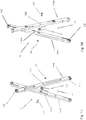
FIGS. 1A-1F respectively illustrate an embodiment of the reflectarray comprising the deployable structure for use in establishing the reflectarray antenna in an undeployed state, at the onset of deployment, partially deployed, further partially deployed, yet further partially deployed, and fully deployed; -
FIG. 2 illustrates a portion of a first embodiment of an endless pantograph structure suitable for use in the deployable structure shown inFIG. 1 ; -
FIG. 3 illustrates a portion of second embodiment of an endless pantograph structure suitable for use in the deployable structure shown inFIG. 1 ; -
FIG. 4 illustrates a portion of a sub-pantograph of the embodiment of a portion of an endless pantograph illustrated inFIG. 2 and pins associated with the ends of two of the legs of the sub-pantograph that limit the extent to which the sub-pantograph is deployed; -
FIGS. 5A and 5B are two perspective exploded views of two crossing legs of the embodiment of a portion of an endless pantograph illustrated inFIG. 2 that illustrate the mid-point pivot connection between the two legs and the spring associated with the mid-point pivot connection; -
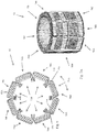
FIG. 6 is a top view of the embodiment of an endless pantograph (in an undeployed state) associated with the reflectarray antenna comprising the deployable structure shown inFIG. 1 and the limiting pins associated with the endless pantograph; -
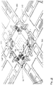
FIGS. 7A-7D respectively illustrate the embodiment of the endless pantograph shown in theFIG. 6 in an undeployed state, at the onset of deployment, further partially deployed, and fully deployed; -
FIG. 8 illustrates an embodiment of a vertex structure that is used to connect two of the composite stacked linear sub-pantographs of the of the endless pantograph shown inFIG. 6 ; -
FIG. 9 illustrates a connector structure for connecting a flexible reflectarray to the endless pantograph illustrated inFIG. 6 ; -
FIG. 10 illustrates a connector structure for connecting a tape to the endless pantograph illustrated inFIG. 6 ; -
FIG. 11 illustrates a satellite that includes the reflectarray antenna comprising the deployable structure illustrated inFIGS. 1A-1F and with the flexible reflectarray in the deployed state; -
FIG. 12 illustrates the motorized tape cassettes and feed antenna associated with the base of the reflectarray antenna comprising the deployment structure shown inFIGS. 1A-1F ; -
FIG. 13 is an exploded view of the motorized tape cassettes, feed antenna, and base of the reflectarray antenna comprising the deployment structure shown inFIGS. 1A-1F ; and -
FIG. 14 illustrates the base of the reflectarray antenna comprising the deployment structure inFIGS 1A-1F and the pairs of serpentine flexures that facilitate rotation of the each of the motorized tape cassettes about an axis that is perpendicular to the base. - With reference to
Figs. 1A-1F , an embodiment of a reflectarray antenna comprising adeployable structure 20 for use in establishing the reflectarray antenna (hereinafter referred to as "thedeployable structure 20") is described. Thedeployable structure 20 conforms to a design specification which requires thedeployable structure 20, in the undeployed state, to fit within a volume that is 20 cm x 20 cm x 25 cm. Additional, thedeployable structure 20 is required to have a mass of no more than 4 kg. Although thedeployable structure 20 conforms to the this design specification, it should be appreciated that adaptation to other form factors and mass requirements is feasible. - Generally, the
deployable structure 20 includes acanister 22, afeed antenna 24, aflexible reflectarray 26, and adeployment mechanism 28. - With reference to
Figs. 1A-1E , thecanister 22 serves to store thefeed antenna 24,flexible reflectarray 26, and thedeployment mechanism 28 in an undeployed state and provides a base for supporting thefeed antenna 24,flexible reflectarray 26, and thedeployment mechanism 28 in the deployed state. With reference toFig. 1A , when thedeployable structure 20 is in the undeployed state, thecanister 22 conforms to the design specification that requires the undeployed structure to fit within a volume that is 20 cm x 20 cm x 25 cm. Within this specific volume, thefeed antenna 24 occupies a first volume within thecanister 22, theflexible reflectarray 26 is folded so as to conform to a second volume within thecanister 22, and thedeployment mechanism 28 is in an undeployed state that conforms to a third volume within the canister. With reference to Fig. IF, when thedeployable structure 20 is in the deployed state, thecanister 22 and thedeployment mechanism 28 cooperate to position the deployedflexible reflectarray 26 relative to thefeed antenna 24 so as to conform to a reflectarray antenna structure with an offset feed, i.e., the boresight of thefeed antenna 24 is not parallel to a line perpendicular to the plane of the deployedflexible reflectarray 26. - With continuing reference to
Figs. 1A-1F , thecanister 22 generally comprises abase 32 and four spring-loaded andlatchable doors 34A-34D that form the sides of the cube and the top of the cube. Areleasable latch structure 36 holds thedoors 34A-34D in the undeployed state shown inFIG. 1A . Thereleasable latch structure 36 can take a number of different forms. In the illustrated embodiment, thelatch 36 employs a meltable pin that disintegrates upon the application of an electrical current, thereby allowing the spring loadeddoors 34A-34D to deploy as shown inFIG. 1B . It should be appreciated that other embodiments of a canister that conforms to the design specification and are suitable for use thefeed antenna 24,flexible reflectarray 26, anddeployment mechanism 28 are feasible. Moreover, embodiments of canisters that conform to other dimensional requirements and that support other embodiments of a feed antenna, flexible reflectarray, and deployment mechanism appropriate for these other dimensional requirements or other application are feasible. - With continuing reference to
Figs. 1A-1E , thefeed antenna 24 is an antenna that is capable of feeding theflexible reflectarray 26 when thedeployable structure 20 is in the deployed state. In the illustrated embodiment, thefeed antenna 24 is a low-profile phased array antenna. In other embodiments, a horn antenna is employed for the feed antenna. - With continuing reference to
Figs. 1A-1E , theflexible reflectarray 26 includes: (a) a first flexible membrane that supports an array of reflectarray elements and (b) a second flexible membrane that serves as a ground plane in the deployed state. A specified distance between the first flexible membrane and the second flexible must be maintained for proper operation of theflexible reflectarray 26 when deployed. This spacing can be achieved in a number of different ways. For example, connectors that attached theflexible reflectarray 26 to thedeployment mechanism 28 and the tension applied to theflexible reflectarray 26 by thedeployment mechanism 28 can be used to maintain the required spacing between the first and second flexible membranes and with only open space between the two membranes. Another alternative is to place a compressible and flexible dielectric structure between the first and second flexible membranes to facilitate the desired spacing between the membranes. Yet another option is to employ substantially non-compressible post like structures at various locations between the membranes to facilitate the desired spacing between the membranes. Generally, when theflexible reflectarray 26 is in the deployed state, theouter edge 48 of the reflectarray defines a polygon-like shape that has catenary-shaped edges instead of straight edges. The flexible characteristic of theflexible reflectarray 26 allows the reflectarray to be folded so as to fit within a specified volume within thecanister 22 when the reflectarray is in the undeployed state. Other flexible reflectarrays known to those skilled in the art are feasible. - With continuing reference to
Figs. 1A-1F , thedeployment mechanism 28 comprises: (a) anendless pantograph 52 for transitioning theflexible reflectarray 26 between an undeployed, folded state and a deployed state in which theflexible reflectarray 26 is substantially planar and (b) atape dispensing structure 54 that operates to position thefeed antenna 24 and theflexible reflectarray 26 relative to one another so to conform to a reflectarray antenna structure with an offset feed. Characteristic of theendless pantograph 52 and other endless pantographs is that the pantograph forms a closed loop and the perimeter defined by the pantograph has a first length in the undeployed state and a second length that is greater than the first length when the pantograph is transitioning from the undeployed state towards and at the deployed state. - With reference to
FIGS. 1A-1F ,2 , and6 , theendless pantograph 52 is an endless polygonal pantograph, i.e., the pantograph has a polygonal shape when undeployed and when fully deployed. More specifically, thepantograph 52 is a composite polygonal pantograph that includes two eight-sided polygonal sub-pantographs. In the illustrated embodiment, each of the eight-sided polygonal sub-pantographs comprises eight linear sub-pantographs with each linear sub-pantograph having one end attached to the end of a second linear sub-pantograph and the other end attached to a third linear sub-pantograph. Thepantograph 52 is more specifically characterized as a stacked polygonal pantograph with: (a) a first eight-sided polygonal sub-pantograph 76A in which the links of the pantograph occupy a first polygonal cylindrical volume and (b) a second eight-sided polygonal sub-pantograph 76B in which the links of the pantograph occupy a second polygonal cylindrical volume that is within the volume defined by the interior surface of the first polygonal cylindrical volume, (c) each side of the second eight-sided polygonal sub-pantograph 76B pivotally engaged to a corresponding side of the first eight-sided polygonal sub-pantograph 76A, and (d) each side of thepantograph 52 connected to two adjacent sides of the pantograph. Thepantograph 52 can also be characterized as eight stacked linear sub-pantographs 78A-78H with each stacked linear sub-pantograph having one end attached to the end of a second stacked linear sub-pantograph and the other end attached to a third stacked linear sub-pantograph. Each of the stacked linear sub-pantographs 78A-78H can be characterized as having a first and secondlinear sub-pantographs pantograph 52 has eight sides, it should be appreciated that an endless polygonal pantograph can have three or more sides. The pivotal attachment between the first eight-sided polygonal sub-pantograph 76A and the second eight-sided polygonal sub-pantograph 76B establishes a 180° offset between the first and second eight-sided polygonal sub-pantographs. More specifically, the two linear sub-pantographs that are embodied in each of the stacked linear sub-pantographs 78A-78H have an offset of 180°. This offset renders thepantograph 52 stiffer in the deployed state than a pantograph in which each side of the pantograph is realized with single linear sub-pantograph. - With reference to
FIGS. 4 ,5A, and 5B , at least one of the linear sub-pantographs 80A, 80B of at least one of the stacked linear sub-pantographs 78A-78H employs a limiting structure that limits the extent to which theendless pantograph 52 deploys. To elaborate, each of the linear sub-pantographs 80A, 80B has at least one pair of crossinglegs crossing leg 150A is apin 152 that projects away from the crossing leg and is positioned so as to engage another leg of the linear sub-pantograph when the relative rotation of the two legs during deployment of the pantograph has resulted in establishing a predetermined angle between the two legs, thereby limiting the deployment of whichever one of the sub-pantographs 80A, 80B thepin 152 is associated, as well as the entireendless pantograph 52. In the illustrated embodiment of theendless pantograph 52, each of the linear sub-pantographs 80A, 80B includes a first set ofparallel legs 154 and a second set ofparallel legs 156. Associated with each full length leg of the first set ofparallel legs 154 are two pins that each engage a different leg of the second set ofparallel legs 156 to limit the deployment of the sub-pantograph with which the pins are associated, the deployment of the sub-pantograph to which the sub-pantograph is pivotally attached, and the deployment of theendless pantograph 52. Due to the offset be the linear sub-pantographs 80A, 80B, there are partial legs that are shorter than the full length legs. Depending on the implementation, there may be one pin or no pins that perform a limiting function associated with a partial leg. The use of multiple pins to limit the deployment of theendless pantograph 52 provides redundancy, i.e., one or more pins can fail and the remaining pin or pins still limit the deployment as desired. Further, the use of multiple pins serves with respect to linear sub-pantographs 80A, 80B serves to "stiffen" the pantographs, i.e., reduce the dead band (droop or sag) that may be present when the linear sub-pantograph is deployed, especially when the deployed pantograph extends over a considerable distance and/or is subject to certain loads. The use of multiple pins also reduces tolerancing requirements. Additionally, the use of multiple pins distributes the load being supported by the sub-pantograph over the length of the pantograph. It should be appreciated by those skilled in the art that fewer or more pins or comparable structure can be employed with a sub-pantograph and/or the locations of the pins altered and the benefits scaled accordingly. - With continuing reference to
FIGS. 5A-5B , to provide energy for transitioning theendless pantograph 52, a spring structure is utilized that stores potential energy when theendless pantograph 52 is in the undeployed state. In deployment, this potential energy is converted to kinetic energy to facilitate the transition of the pantograph from the undeployed state towards the deployed state. With reference toFIGS. 5A-5B , an embodiment of a spring structure 90 is described. Generally, a spring structure can be located at any pivot point of a pantograph associated with theendless pantograph 52. Further, a single spring structure can potentially provide the energy needed to transition theendless pantograph 52 between the undeployed and deployed states. However, in the illustrated embodiment of theendless pantograph 52, a spring structure is located at each of multiple pivots points of theendless pantograph 52. The spring structure 90 is associated with apivot structure 92 that is used to establish a center pivot point between the pair of crossing legs orlinks pivot structure 92 includes afirst hole 98A associated withcross leg 150A, asecond hole 98B associated with crossingleg 150B, anut 100, and screw 102 that extends through each of the holes and engages the nut to establish a pivot connection between the crossinglegs nut 100,secrew 102 andholes torsion spring 104, afirst housing 106A that is associated with crossingleg 150A and adapted to engage one leg of the spring, and asecond housing 106B that is associated with thecrossing leg 150B and adapted to engage the other leg of the spring. The first andsecond housings legs torsion spring 104. - With reference to
FIG. 1A , when theendless pantograph 52 is in the undeployed state, theendless pantograph 52 is constrained by the canister 22 (which is also in the undeployed state) such that spring structure located at each of the pivots points associated with theendless pantograph 52 is storing potential energy and the cumulative potential energy stored by all of the spring structures is sufficient to deploy theendless pantograph 52. During deployment, the constraint on theendless pantograph 52 is removed and the potential energy stored in each spring structure 90 associated with theendless pantograph 52 is converted to kinetic energy that is used to transition theendless pantograph 52 from the undeployed state towards the deployed state. With reference toFIGS. 7A-7D , the transition of theendless pantograph 52 from the undeployed state to the fully deployed state using the spring structures is illustrated. The spring structure 90 is also designed so that, even when thepantograph 52 is fully deployed, the spring structures cumulatively store potential energy sufficient to substantially maintain theendless pantograph 52 in the deployed state for the reasonably anticipated loads that the pantograph andflexible reflectarray 26 are expected to encounter. Further, the spring structure 90 is also preferably designed to provide sufficient energy to deploy and maintain theendless pantograph 52 andflexible reflectarray 26 in the deployed state even if a predetermined number of the spring structures fail. While theendless pantograph 52 employs a spring structure 90 at each pivot point, embodiments that employ fewer spring structures are feasible. It should be appreciated that many different types of spring structures known to those skilled in the art can be employed to provide the energy for deploying an endless pantograph, including spring structures that employ different types of springs that engage the links of an endless pantograph in a different way. - With reference to
FIG. 2 , the linear sub-pantographs 80A, 80B of each of the stacked linear sub-pantographs 78A-78H are pivotally connected to one another. To elaborate, the outer full-length legs of the firstlinear sub-pantograph 80A and the inner full-length legs of the firstlinear sub-pantograph 80A are each adapted for engagement within the firstlinear sub-pantograph 80A at pivot points 81A-81C. If the firstlinear sub-pantograph 80A has any partial legs, the partial legs are adapted for pivotal engagement within the firstlinear sub-pantograph 80A at two pivot points. Similarly, the outer full-length legs of the secondlinear sub-pantograph 80B and the inner full-length legs of the secondlinear sub-pantograph 80B are each adapted for engagement within the secondlinear sub-pantograph 80B at pivot points 81D-81F. If the secondlinear sub-pantograph 80B has any partial legs, the partial legs are adapted for pivotal engagement within the secondlinear sub-pantograph 80B at two pivot points. With respect to the pivot connection between the first and secondlinear sub-pantographs first sub-pantograph 80A and the inner full-length legs of thesecond sub-pantograph 80B are each adapted for engagement atpivot points first sub-pantograph 80A or the inner legs of the of thesecond sub-pantograph 80B be a partial leg, the partial leg is adapted for engagement at one pivot point. - With reference to
FIG. 3 , while theendless pantograph 52 employs stacked linear sub-pantographs 78A-78H, an interlacedlinear sub-pantograph 160 can also be employed. The interlacedlinear sub-pantograph 160 includes a firstlinear sub-pantograph 162A and a secondlinear sub-pantograph 162B that are interlaced with one another. Characteristic of the interlacedlinear sub-pantograph 160 is that one of the two legs forming a crossing pair of legs in the firstlinear sub-pantograph 162A underlies two legs associated with the secondlinear sub-pantograph 162B and the other one of the two legs forming a crossing pair of legs in the firstlinear sub-pantograph 162A overlies two legs associated with the secondlinear sub-pantograph 162B. As such, the first and secondlinear sub-pantograph linear sub-pantograph 160 can be adapted to employ a limiting structure and/or spring structure comparable to those structures described with respect to the stacked linear sub-pantographs 78A-78H. It should also be appreciated that in particular circumstances a circular endless pantograph can be employed (i.e., an endless pantograph that is circular in the undeployed and deployed states). Further, a circular pantograph can employ a limiting structure and spring structure comparable to those structures described with respect to the stacked linear sub-pantographs 78A-78H. - With reference to
FIGS. 8 and 9 , avertex structure 82 is utilized to connect the end of one of the stacked linear sub-pantographs 78A-78H to the end of another of the stackedlinear pantographs 78A-78H. Thevertex structure 82, in addition to connecting two stacked linear pantographs to one another, also maintains the angle between the two linear stacked pantographs. In the stacked polygonal pantograph embodiment of thepantograph 52, the interior angle between each pair of adjacent linear stacked pantographs is approximately 135°. Thevertex structure 82 includes: (a) ahousing 84A that engages two center pivot points, one center pivot point associated with one of the stacked linear sub-pantographs and the other center pivot point associated with the other stacked linear sub-pantograph, (b) afirst bushing 84B that engages the two end pivot points, one end pivot point associated with one of the stacked linear sub-pantographs and the other end pivot point associated with the other stacked linear sub-pantograph, and (c) asecond bushing 84C that engages the two end pivot points, one end pivot point associated with one of the stacked linear sub-pantographs and the other end pivot point associated with the other stacked linear sub-pantograph. Each of thehousing 84A and first andsecond bushings first pin 85A that is substantially perpendicular to a first face and asecond pin 85B that is substantially perpendicular to a second face. The interior angle between the faces is approximately 135° and the angle between the two pins is approximately 45°. Each of the pins pivotally engages a hole in a leg associated with one of the pantographs such that the link can rotate about the pin. The 45° angle between the pairs of pins associatedhousing 84A andbushings vertex structure 82 also includes apin 86 that is located within a hole associated with each of thehousing 84A andbushings pin 86 is fixed relative to thehousing 84A, i.e., linear relative movement between the pin and thehousing 84A is prevented. However, linear relative movement between thepin 86 and the other twobushings endless pantograph 52 is in an undeployed state, thehousing 84A is separated from each of thebushings FIGS. 7A-7D , as theendless pantograph 52 transitions toward the deployed state, the distance between thehousing 84A and each of thebushings vertex structures 82 operates to maintain the approximately 135° angle between the two stacked linear sub-pantographs engaged by thevertex structure 82 as theendless pantograph 52 transitions between the undeployed and deployed states. - With reference to
Fig. 9 , an embodiment of aconnector 120 for establishing a connection between theflexible reflectarray 26 and theendless pantograph 52 is described. Generally, theconnector 120 includes atension spring 122A, afirst interface 122B for engaging thetension spring 122A and theflexible reflectarray 26, and asecond interface 122C for engaging the tension spring 122 and theendless pantograph 52 or, more specifically, thevertex structure 82 of theendless pantograph 52. Thefirst interface 122B employs aspacer structure 122D to facilitate a desired spacing between the two membranes of theflexible reflectarray 26. In the illustrated embodiment,multiple connectors 120 are employed, one for connecting the reflectarray to each of the vertex structures. The use of a tension spring allows stresses placed on theflexible reflectarray 26 during deployment and possibly after full deployment to be accommodated. Other connectors known to those skilled in the art that are capable of absorbing potentially undesirable stresses placed upon theflexible reflectarray 26 are feasible. Further, in certain applications, a connector that is capable of absorbing such potential stresses may be unnecessary or undesirable. In such applications, a connector with little, if any, ability to absorb such stresses can be employed. - With reference to
FIGS. 1D-1F and12-14 , thetape dispensing structure 54 includes fourmotorized tape cassettes 130A-130D that respectively support "carpenter"tapes 132A-132D. Each of thetapes 132A-132D has an end that is operatively connected to or wrapped about a spindle of themotorized tape cassette 130A-130D with which the tape is associated. With reference toFIG. 10 , the other end of each of thetapes 132A-132D is operatively connected to one of thevertex structures 82 of theendless pantograph 52. When thetapes 132A-132D are in the undeployed state, a substantial portion of each of the tapes is wound around the spindle. When thetapes 132A-132C are in the deployed state, a substantial portion of each of the tapes linearly extends between the motorized tape cassette and the deployed endless pantograph 52 (e.g., FIG. IF). Each of thetapes 132A-132D is a quasi-dual stable tape that exhibits: (a) a first stable state when the entire tape is wound or rolled, (b) a second stable state when the entire tape is straight, and (c) a propensity to transition towards the second stable state when a portion of the tape is in the first state and another portion of the tape is in the second state. As such, when each of thetapes 132A-132D is in the undeployed state in which a substantial portion of the tape is wound around a spindle and a portion of the tape is straight, each of the tapes is storing potential energy that can be used to facilitate the transition of the tape from undeployed state to the deployed state in which a substantially portion of the tape linearly extends between the motorized tape cassette and the deployedendless pantograph 52. Thetapes 132A-132D have different lengths. As such, when thetapes 132A-132D are in the deployed state (e.g., FIG. IF), thefeed antenna 24 and the deployed,flexible reflectarray 26 are in an offset feed configuration in which the boresight of thefeed antenna 24 is not parallel to a line perpendicular to the deployed,flexible reflectarray 26. In the illustrated embodiment, thetape 132A is longer thantapes 132B-132D,tapes tape 132D is shorter thantapes 132A-132C. - With continuing reference to
FIGS. 1D-1F and12-14 , thetapes 132A-132D are employed during deployment to move theendless pantograph 52 away from thefeed antenna 24. As such, the angle of each of thetapes 132A-132D relative to theendless pantograph 52 changes during deployment. With reference toFIG. 10 , to accommodate this change in the angle, the end oftape 132A is attached to theendless pantograph 52 and, more specifically, to thehousing 84A by ahinge joint 170. Theother tapes 132B-132D are also attached to theendless pantograph 52 by hinge joints. The oppostite ends of each of thetapes 132A-132D also accommodate this change in angle. With reference toFIGS. 12 and13 , each of themotorized tape cassettes 130A-130D is attached to thebase 32 of thecanister 22 by a mountingstructure 172. The mountingstructure 172 includes a pair of mountingstandards base 32. The mountingstandards pin 176A that is established in afirst hole 178A associated with the motorized tape cassette and the mounting standard 174B includes a mountingpin 176B that engages a second hole 178B associated the motorized tape cassette. Thepins holes 178A, 178B are collinear and define an axis about which the motorized tape cassette can rotate during deployment of the associated tape. - In certain embodiments and in certain situations, the deployment of the tapes may produce a twist, i.e., a rotation of the
endless pantograph 52 andflexible reflectarray 26 about an axis that is perpendicular to thebase 32. To accommodate such a twist and prevent undue stress from being placed on the tapes, the mountingstructure 172 associated with each of themotorized tape cassettes 130A-130D includes arotation structure 180 that allows the associated motorized tape cassette to rotate about an axis that is perpendicular to thebase 32. In the illustrated embodiment and with reference toFIGS. 13 and14 , therotation structure 180 comprises a pair ofserpentine flexures standards serpentine flexures base 32. - An embodiment of a tape dispensing structure in which three tapes are employed, rather than four tapes, is feasible. Further, an embodiment in which more than four tapes is employed is also feasible. Also feasible in certain embodiment are other types of extendable structures, such as telescoping rods, tapes that are folded in a serpentine fashion when in an undeployed state and extend linearly in a deployed state, spring-loaded structures characterized by rods or beams with a spring structure extending between the rods or beams that allows the rods or beams to be folded when undeployed and to adopt an extended structure when deployed, to name a few.
- Associated with the
deployment mechanism 28 are four pairs oflanyards 190A-190D with each pair of lanyards operatively attached to thesame vertex structure 82 to which one of thetapes 132A-132D is attached. The four pairs oflanyards 190A-190D respectively cooperate with the fourtapes 132A-132D to form four truss-like structures that enhance the stability of the deployedendless pantograph 52 and deployedflexible reflectarray 26. In the undeployed state, each lanyard is stored inlanyard storage device 192 that, in the illustrated embodiment, comprises a group of tubes disposed in a parallel manner. In the undeployed state, the group of tubes store a lanyard such that the lanyard follows a serpentine path. During deployment, each of the lanyards is extracted from itslanyard storage device 192 as thetapes 132A-132D are dispensed by themotorized tape cassettes 130A-130D. - With reference to
FIGS. 1A-1F , the transition of thedeployable structure 20 between the undeployed and deployed states is described. With reference toFIG. 1A , thedeployable structure 20 is in the undeployed state. Deployment commences with an electrical current being applied to the meltable pin associated with thereleasable latch structure 36 to release the latch and allow the spring-loadeddoors 34A-34D to deploy, as shown inFIG. 1B . At this point, thedoors 34A-34D are no longer constraining theendless pantograph 52 or thetapes 132A-132D. The spring structures associated with theendless pantograph 52 endeavor to deploy theendless pantograph 52. However, themotorized tapes cassettes 130A-130D allow the operation of the spring structures to be controlled or damped. In any event, theendless pantograph 52 and theflexible reflectarray 26 begin to deploy and thetapes 132A-132D begin to dispense so as to move theendless pantograph 52 and theflexible reflectarray 26 away from thefeed antenna 24, as shown inFIGS 1D-1F . The deployment of theendless pantograph 52 and theflexible reflectarray 26 continues until further deployment of theendless pantograph 52 is prevented by the limit structure associated with theendless pantograph 52, which is the plurality of pins in the illustrated embodiment. At this point, theflexible reflectarray 26 is a substantially flat or planar and constitutes an operable reflectarray. The deployment of thetapes 132A-132D continues until each of thetapes 132A-132D has reached a predetermined length. If theflexible reflectarray 26 is fully deployed at this point, thetapes 132A-132D have positioned theflexible reflectarray 26 relative to thefeed antenna 24 so as to operatively position the reflectarray and the feed antenna for use in an reflectarray antenna with an offset feed, as shown in FIG. IF. - With reference to
Fig. 11 , asatellite 140 that includes thedeployable structure 20 andother satellite elements 142. Thedeployable structure 20 operates such that upon full deployment, thefeed antenna 24 is positioned between the deployed,flexible reflectarray 26 and theother satellite elements 142. - In certain embodiments, the potential energy stored in undeployed tapes may provide sufficient radial force to deploy the endless pantograph and thereby eliminate the need for any spring structure/structures associated with the endless pantograph. The operation of such tapes may or may not be supplemented by the use of one or more electric motors. If supplemented by one or more electric motors, one function of the motor(s) would be to control or dampen the deployment of the tapes. In yet other embodiments, extendable structures other than tapes can be employed. For instance, telescoping rods and other extendable structure can be employed. Further, other extendable structures that employ other motive forces, such as pneumatic or hydraulic forces, can be employed. It should also be appreciated that the endless pantograph structure is not limited to deploying a flexible reflectarray. The endless pantograph can be used to deploy other flexible structures in space-based applications, such flexible solar panels, solar sails, and the like. It should also be appreciated that the endless pantograph can be used to deploy flexible membrane structure other than a flexible reflectarray. For instance, the endless pantograph structure can be used to deploy a flexible solar cell array or solar sail. Further, while the deployment structure has largely been described with respect to its use in implementing an offset reflectarray antenna, the deployment structure is believed to be adaptable to the implementation of other reflectarray antenna structures, such as center fed reflectarray antennas, center fed Cassegrain reflectarray antennas, and offset fed Cassegrain reflectarray antennas, to name a few.
- The foregoing description of the invention is intended to explain the best mode known of practicing the invention and to enable others skilled in the art to utilize the invention in various embodiments and with the various modifications required by their particular applications or uses of the invention.
Claims (16)
- A reflectarray antenna comprising: a deployable structure for use in establishing the reflectarray antenna, the deployable structure comprising:a base (32);a feed antenna (24) for use in the reflectarray antenna;a flexible electrical element (26) for use in the reflectarray antenna;wherein the flexible electrical element (26) is folded in an undeployed state;wherein the flexible electrical element (26) is unfolded in a deployed state relative to the undeployed state; anda deployment mechanism (28) for transitioning the flexible electrical element (26) from the undeployed state towards the deployed state;wherein the deployment mechanism (28) includesan endless structure (52) forming a closed loop, defining a perimeter that has a first length in the undeployed state and a second length that is greater than the first length when the endless structure transitions from the undeployed state towards the deployed state; and operatively engaged to the flexible electrical element (26); andan energy providing device (90) for use in transitioning the endless structure from the undeployed state towards the deployed state;wherein, when the endless structure transitions from the undeployed state towards the deployed state, the flexible electrical element (26) is configured to transition from being folded in the undeployed state towards being unfolded;wherein the endless structure is an endless pantograph structure;the deployment mechanism (28) comprises a plurality of tapes (132A-132D) with each tape having a first end that is operatively connected to the base and a second end that is operatively connected to the endless pantograph structure;wherein each tape of the plurality of tapes (132A-132D) is adapted to transition from an undeployed state in which the endless pantograph structure is located at a first position relative to the base towards a deployed state in which the endless pantograph structure is located at a second position relative to the base that is a greater distance from the base than the first position;and wherein the flexible electrical element (26) comprises a two-layer reflectarray membrane supporting an array of radiating elements.
- A reflectarray antenna, as claimed in claim 1, wherein the endless pantograph structure includes a first pantograph (76A) and a second pantograph (76B) that is pivotally connected to the first pantograph about an axis in the plane of the deployed two-layer reflectarray membrane.
- A reflectarray antenna, as claimed in claim 1, wherein the endless pantograph structure has a polygon shape with at least first, second, and third sides (78A-78C), the structure comprising a vertex structure (82) between each pair of sides, and a connector (120) for connecting the two-layer reflectarray membrane (26) to the vertex structure.
- A reflectarray antenna, as claimed in claim 1, further comprising:
a limiter (152) for limiting the extent to which the endless pantograph structure can be deployed. - A reflectarray antenna, as claimed in claim 1, further comprising:
a plurality of limiters (152, 152), each limiter operatively connected to a first leg of the endless pantograph structure and adapted to engage a second leg of the endless pantograph structure that is pivotally connected to the first leg when relative rotation of the first and second legs establishes a predetermined angle between the first and second legs and prevents further rotation of the first and second legs relative to one another. - A reflectarray antenna, as claimed in claim 5, wherein the energy providing device includes a spring (104) that operatively engages first and second legs of the endless pantograph structure, the spring storing a first amount of potential energy in the undeployed state and a second amount of potential energy that is less than the first amount of potential energy when the endless pantograph structure transitions from the undeployed state towards the deployed state.
- A reflectarray antenna, as claimed in claim 5 or 6, wherein the energy providing device includes a plurality of springs (104), wherein each spring of the plurality of springs operatively engages a different pair of legs of the endless pantograph structure.
- A reflectarray antenna, as claimed in claim 1, wherein the energy providing device includes a plurality of electric motors (130A-130D) with each motor of the plurality of motors operatively engaging a tape of the plurality of tapes such that each tape of the plurality of tapes is engaged by one motor of the plurality of motors.
- A reflectarray antenna, as claimed in claim 1, wherein a first tape of the plurality of tapes has a first deployed length and a second tape of the plurality of tapes has a second deployed length to facilitate establishing an offset feed positional relationship between the feed antenna and the flexible electrical element when the flexible electrical element is in the deployed state.
- A reflectarray antenna, as claimed in any one of the preceding claims, wherein:
the endless pantograph structure has eight vertices and four tapes. - A reflectarray antenna, as claimed in claim 1, wherein each tape of the plurality of tapes has a substantial portion disposed in a roll in the undeployed state and a substantially portion of the tape disposed in a linear manner in the deployed state.
- A reflectarray antenna, as claimed in claim 9, wherein:a third tape of the plurality of tapes has a third deployed length;wherein the third length is different than the first and second deployed lengths of the first and second tapes.
- A reflectarray antenna, as claimed in claim 1, further comprising:a tape cassette (130A) for storing a substantial portion of a tape in a roll disposed about a tape axis when the tape is in an undeployed state and a swivel structure (180) that operatively connects the tape cassette to the base;wherein the swivel structure allows the tape cassette to rotate about the tape axis and is biased to allow the tape cassette to rotate about a transverse axis that is substantially perpendicular to the tape axis.
- A reflectarray antenna, as claimed in claim 13, wherein the swivel structure includes a pair of serpentine flexures (182A, 182B).
- A reflectarray antenna, as claimed in claim 1, wherein:the base is operatively connected to the plurality of tapes and is adapted for connection to a satellite structure so as to operatively connect the base, deployment mechanism, and flexible electrical element to the satellite structure;wherein, when the flexible electrical element is in the deployed state, the plurality of tapes are structurally located between the flexible electrical element and the base.
- A reflectarray antenna, as claimed in any one of the preceding claims, wherein:
at least one tape of the plurality of tapes is a quasi-dual stable tape.
Applications Claiming Priority (2)
| Application Number | Priority Date | Filing Date | Title |
|---|---|---|---|
| US201562233115P | 2015-09-25 | 2015-09-25 | |
| PCT/US2016/053844 WO2017054005A1 (en) | 2015-09-25 | 2016-09-26 | Deployable structure for use in establishing a reflectarray antenna |
Publications (3)
| Publication Number | Publication Date |
|---|---|
| EP3353855A1 EP3353855A1 (en) | 2018-08-01 |
| EP3353855A4 EP3353855A4 (en) | 2019-05-01 |
| EP3353855B1 true EP3353855B1 (en) | 2021-07-07 |
Family
ID=58387542
Family Applications (1)
| Application Number | Title | Priority Date | Filing Date |
|---|---|---|---|
| EP16849901.0A Active EP3353855B1 (en) | 2015-09-25 | 2016-09-26 | Deployable structure for use in establishing a reflectarray antenna |
Country Status (6)
| Country | Link |
|---|---|
| US (3) | US10283835B2 (en) |
| EP (1) | EP3353855B1 (en) |
| CA (1) | CA2999987C (en) |
| IL (2) | IL284760B2 (en) |
| SG (1) | SG10202103957UA (en) |
| WO (1) | WO2017054005A1 (en) |
Families Citing this family (23)
| Publication number | Priority date | Publication date | Assignee | Title |
|---|---|---|---|---|
| US10773833B1 (en) | 2011-08-30 | 2020-09-15 | MMA Design, LLC | Panel for use in a deployable and cantilevered solar array structure |
| US10263316B2 (en) | 2013-09-06 | 2019-04-16 | MMA Design, LLC | Deployable reflectarray antenna structure |
| US10170843B2 (en) | 2015-05-29 | 2019-01-01 | California Institute Of Technology | Parabolic deployable antenna |
| US20170110803A1 (en) * | 2015-07-08 | 2017-04-20 | California Institute Of Technology | Deployable reflectarray high gain antenna for satellite applications |
| EP3353855B1 (en) | 2015-09-25 | 2021-07-07 | MMA Design, LLC | Deployable structure for use in establishing a reflectarray antenna |
| CN107978837B (en) * | 2017-12-21 | 2023-11-17 | 星际漫步(北京)航天科技有限公司 | Inflatable flexible antenna and unfolding method thereof |
| CN108649318B (en) * | 2017-12-27 | 2020-02-04 | 哈尔滨工业大学(深圳) | Spatial triangular table deployable mechanism based on rigid scissor fork mechanism |
| FR3081083A1 (en) * | 2018-05-08 | 2019-11-15 | Macdonald, Dettwiler And Associates Corporation | REFLECTIVE REFLECTIVE NETWORK ANTENNA REFLECTOR WITH DEPLOYABLE AND LIGHT OPENING |
| CN109050979B (en) * | 2018-07-20 | 2021-08-17 | 广西大学 | Shear type folding and unfolding unit rigid hinge connection large-space unfoldable mechanism |
| CN109080853A (en) * | 2018-07-20 | 2018-12-25 | 广西大学 | One kind imitating cobweb space development agency based on diamond-shaped element |
| EP3912224A4 (en) | 2019-01-18 | 2022-10-05 | M.M.A. Design, LLC | Deployable system with flexible membrane |
| US11942687B2 (en) * | 2019-02-25 | 2024-03-26 | Eagle Technology, Llc | Deployable reflectors |
| CN110828965A (en) * | 2019-09-30 | 2020-02-21 | 中国空间技术研究院 | Conical annular truss deployable antenna structure based on wheel type synchronous rotating mechanism |
| CN110970701A (en) * | 2019-09-30 | 2020-04-07 | 中国空间技术研究院 | Conical single-layer annular truss deployable antenna mechanism driven by torsion spring |
| CN111146557B (en) * | 2019-12-14 | 2022-03-15 | 中国电子科技集团公司第三十九研究所 | Light flexible inflatable deployable dipole antenna structure |
| US11223111B2 (en) * | 2020-06-11 | 2022-01-11 | Eagle Technology, Llc | Systems and methods for providing antennas with mechanically coupled offset positions |
| US20220102868A1 (en) * | 2020-08-14 | 2022-03-31 | M.M.A. Design, LLC | Deployable electromagnetic radiation directing lens system |
| CN112599185B (en) * | 2020-09-21 | 2022-04-12 | 北京交通大学 | Dual-mode scaling mechanism |
| KR102435720B1 (en) * | 2020-10-14 | 2022-08-25 | 연세대학교 산학협력단 | Aparatus for deploy membrane for a satellite |
| CN112531315B (en) * | 2020-11-27 | 2021-11-30 | 浙江大学 | Synchronous unfolding mechanism for satellite-borne phased-array antenna |
| US11411318B2 (en) | 2020-12-08 | 2022-08-09 | Eagle Technology, Llc | Satellite antenna having pantographic trusses and associated methods |
| CN112591142B (en) * | 2020-12-14 | 2022-11-08 | 兰州空间技术物理研究所 | Storage device suitable for flexible spacecraft |
| US20230044114A1 (en) * | 2021-08-04 | 2023-02-09 | M.M.A. Design, LLC | Multi-direction Deployable Antenna |
Family Cites Families (84)
| Publication number | Priority date | Publication date | Assignee | Title |
|---|---|---|---|---|
| US3010372A (en) | 1960-02-11 | 1961-11-28 | Wade E Lanford | Folding apparatus |
| US3710806A (en) | 1971-10-27 | 1973-01-16 | V Kelly | Erectable building structure |
| US4133501A (en) | 1975-09-30 | 1979-01-09 | Communications Satellite Corporation | Self-deployable solar cell panel |
| US4375878A (en) | 1980-10-28 | 1983-03-08 | Lockheed Missiles & Space Company, Inc. | Space satellite with agile payload orientation system |
| US4380013A (en) * | 1981-02-17 | 1983-04-12 | General Dynamics Corp./Convair Division | Expandable panel and truss system/antenna/solar panel |
| US4419828A (en) | 1981-05-19 | 1983-12-13 | Farris David L | Apparatus for establishing the junction contour for intersecting pipes |
| US4475323A (en) * | 1982-04-30 | 1984-10-09 | Martin Marietta Corporation | Box truss hoop |
| IT1162948B (en) | 1983-09-30 | 1987-04-01 | Aeritalia Spa | EXTENSIBLE ARM PARTICULARLY FOR VEHICLES OR SPACE MODULES |
| US5040907A (en) | 1990-02-13 | 1991-08-20 | Aec-Able Engineering Co. | Bearing system with redundancy of races |
| US5228644A (en) | 1991-05-28 | 1993-07-20 | The United States Of America As Represented By The United States National Aeronautics And Space Administration | Solar powered system for a space vehicle |
| US5189773A (en) | 1991-07-15 | 1993-03-02 | Aec-Able Engineering Co., Inc. | Mast forming and deployment system |
| US5218375A (en) | 1991-11-15 | 1993-06-08 | Antenna Products Corporation | Rapidly extendible and retractable antenna mast |
| US5296044A (en) | 1992-03-06 | 1994-03-22 | Aec-Able Engineering Company, Inc. | Lightweight stowable and deployable solar cell array |
| US5298085A (en) | 1992-03-24 | 1994-03-29 | Aec-Able Engineering Company, Inc. | Support blanket for solar cell arrays |
| US5365241A (en) | 1992-06-24 | 1994-11-15 | Williams Lawrence I S | Method and apparatus for performing planar near-field antenna measurement using bi-polar geometry |
| US5680145A (en) | 1994-03-16 | 1997-10-21 | Astro Aerospace Corporation | Light-weight reflector for concentrating radiation |
| US5520747A (en) | 1994-05-02 | 1996-05-28 | Astro Aerospace Corporation | Foldable low concentration solar array |
| US6041800A (en) | 1998-08-07 | 2000-03-28 | Carter; Mark C. | Erectable shelter with gable roof |
| US6470902B1 (en) | 1994-07-25 | 2002-10-29 | United California Bank | Erectable canopy with reinforced roof structure |
| US5511572A (en) | 1994-07-25 | 1996-04-30 | Carter; Mark C. | Collapsible shelter with flexible, collapsible canopy |
| US5644322A (en) | 1995-06-16 | 1997-07-01 | Space Systems/Loral, Inc. | Spacecraft antenna reflectors and stowage and restraint system therefor |
| US5785280A (en) | 1995-07-20 | 1998-07-28 | Space Systems/Loral, Inc. | Hybrid solar panel array |
| US5701923A (en) | 1996-03-07 | 1997-12-30 | Losi, Jr.; Raymond | Collapsible shelter |
| GB9606200D0 (en) | 1996-03-25 | 1996-05-29 | Daton Lovett Andrew J | An extendible member |
| US5864324A (en) * | 1996-05-15 | 1999-01-26 | Trw Inc. | Telescoping deployable antenna reflector and method of deployment |
| US6081234A (en) | 1997-07-11 | 2000-06-27 | California Institute Of Technology | Beam scanning reflectarray antenna with circular polarization |
| US6017002A (en) | 1997-07-21 | 2000-01-25 | Hughes Electronics Corporation | Thin-film solar reflectors deployable from an edge-stowed configuration |
| GB2330007B (en) * | 1997-10-03 | 2002-01-23 | Matra Marconi Space Uk Ltd | Expandable support ring |
| FR2777118B1 (en) * | 1998-04-03 | 2000-06-02 | Aerospatiale | ELASTICALLY DEFORMABLE ANTENNA REFLECTOR FOR A SPACE ENGINE |
| US6104358A (en) * | 1998-05-12 | 2000-08-15 | Trw Inc. | Low cost deployable reflector |
| US6010096A (en) | 1998-07-22 | 2000-01-04 | Space Systems/Loral, Inc. | Deployment restraint and sequencing device |
| US6147294A (en) | 1999-04-06 | 2000-11-14 | Trw Inc. | D-wing deployable solar array |
| US6323827B1 (en) * | 2000-01-07 | 2001-11-27 | Trw Inc. | Micro fold reflector |
| US6419175B1 (en) * | 2001-02-08 | 2002-07-16 | Vulcan Spring & Manufacturing Company | Retractor having a swivel attachment component |
| US6384787B1 (en) | 2001-02-21 | 2002-05-07 | The Boeing Company | Flat reflectarray antenna |
| GEP20053604B (en) * | 2001-06-12 | 2005-08-25 | Space Deployable Antenna Reflector | |
| US6581883B2 (en) | 2001-07-13 | 2003-06-24 | The Boeing Company | Extendable/retractable bi-fold solar array |
| CA2513267C (en) | 2003-02-21 | 2012-04-24 | Variflex, Inc. | Portable shelter with rolling element bearings |
| US7030824B1 (en) | 2003-05-29 | 2006-04-18 | Lockheed Martin Corporation | MEMS reflectarray antenna for satellite applications |
| US6983914B2 (en) | 2004-02-12 | 2006-01-10 | The Boeing Company | Deployable solar array assembly |
| US6970143B2 (en) | 2004-03-16 | 2005-11-29 | Harris Corporation | Highly compact, precision lightweight deployable truss which accommodates side mounted components |
| US7602349B2 (en) | 2006-02-24 | 2009-10-13 | Lockheed Martin Corporation | System of stowing and deploying multiple phased arrays or combinations of arrays and reflectors |
| US7762500B1 (en) * | 2006-11-06 | 2010-07-27 | Sanjay Dhall | Telescopic wing with articulated structural spar |
| US20080283670A1 (en) | 2006-12-13 | 2008-11-20 | Thomas Jeffrey Harvey | K-truss deployable boom system |
| JP5036417B2 (en) * | 2007-06-18 | 2012-09-26 | 株式会社越智工業所 | Structure using bellows type frame |
| US9214892B2 (en) | 2007-11-21 | 2015-12-15 | Orbital Atk, Inc. | Solar arrays |
| US8291781B2 (en) | 2007-12-21 | 2012-10-23 | Schlumberger Technology Corporation | System and methods for actuating reversibly expandable structures |
| US8356774B1 (en) | 2008-04-21 | 2013-01-22 | The United States Of America As Represented By The Secretary Of The Air Force | Structure for storing and unfurling a flexible material |
| FR2933771B1 (en) * | 2008-07-11 | 2010-08-13 | Thales Sa | THERMALLY DEPLOYABLE TAPE METER AND DEPLOYABLE STRUCTURE COMPRISING SAID METER TAPE |
| JP5276952B2 (en) * | 2008-11-05 | 2013-08-28 | サカセ・アドテック株式会社 | Extension structure |
| US10370126B1 (en) | 2009-09-09 | 2019-08-06 | M.M.A. Design, LLC | Solar panel array assembly |
| US8757554B1 (en) | 2009-09-09 | 2014-06-24 | MMA Design, LLC | Deployable and tracked solar array mechanism for nano-satellites |
| US8905357B1 (en) * | 2009-10-02 | 2014-12-09 | MMA Design, LLC | Thin membrane structure |
| US8289221B1 (en) | 2010-06-28 | 2012-10-16 | The United States Of America As Represented By The Secretary Of The Air Force | Deployable reflectarray antenna system |
| US8814099B1 (en) | 2010-08-31 | 2014-08-26 | MMA Design, LLC | Deployable morphing modular solar array |
| US9550584B1 (en) | 2010-09-30 | 2017-01-24 | MMA Design, LLC | Deployable thin membrane apparatus |
| KR20120104855A (en) | 2011-03-14 | 2012-09-24 | 한국전자통신연구원 | Deployable reflectarray antenna |
| US8816187B1 (en) | 2011-04-18 | 2014-08-26 | The Boeing Company | Stowing or deploying a solar array |
| US8720830B1 (en) | 2012-01-30 | 2014-05-13 | United Launch Alliance, L.L.C. | Efficient solar panel wing-stowage on a space launch vehicle |
| US9153860B2 (en) * | 2012-03-15 | 2015-10-06 | European Space Agency | Mechanical support ring structure |
| WO2014081943A1 (en) | 2012-11-21 | 2014-05-30 | Roccor, Llc | Rigid slit-tube overwrapped laminate system |
| WO2014127292A1 (en) | 2013-02-15 | 2014-08-21 | Roccor, Llc | Collapsible roll-out truss |
| US9637248B2 (en) * | 2013-03-15 | 2017-05-02 | The Boeing Company | Component deployment system |
| US9270021B1 (en) | 2013-09-06 | 2016-02-23 | M.M.A. Design, LLC | Low-profile mast array |
| US10263316B2 (en) | 2013-09-06 | 2019-04-16 | MMA Design, LLC | Deployable reflectarray antenna structure |
| US9593485B2 (en) | 2014-03-12 | 2017-03-14 | Roccor, Llc | Deployment system for supported retractable extension of a composite boom |
| EP3059800B1 (en) | 2015-02-17 | 2017-11-08 | MMA Design, LLC | Deployable reflectarray antenna structure |
| US10170843B2 (en) | 2015-05-29 | 2019-01-01 | California Institute Of Technology | Parabolic deployable antenna |
| US10119292B1 (en) | 2015-07-02 | 2018-11-06 | M.M.A. Design, LLC | Deployable boom and deployable boom with solar blanket |
| US20170110803A1 (en) | 2015-07-08 | 2017-04-20 | California Institute Of Technology | Deployable reflectarray high gain antenna for satellite applications |
| WO2017015339A1 (en) | 2015-07-20 | 2017-01-26 | The Regents Of The University Of California | Low-profile circularly-polarized single-probe broadband antenna |
| EP3353855B1 (en) | 2015-09-25 | 2021-07-07 | MMA Design, LLC | Deployable structure for use in establishing a reflectarray antenna |
| US11228115B2 (en) | 2016-01-11 | 2022-01-18 | Tethers Unlimited Inc. | Methods and apparatus for manufacture and in-space assembly of antennas |
| US10256530B2 (en) | 2016-01-28 | 2019-04-09 | Tendeg Llc | Deployable reflector |
| US10418721B2 (en) | 2016-03-29 | 2019-09-17 | California Institute Of Technology | Low-profile and high-gain modulated metasurface antennas from gigahertz to terahertz range frequencies |
| WO2018005532A1 (en) | 2016-06-27 | 2018-01-04 | The Regents Of The University Of California | Monopole rectenna arrays distributed over a curved surface for multi-directional multi-polarization, and multi-band ambient rf energy harvesting |
| US10520132B2 (en) | 2016-11-08 | 2019-12-31 | River Front Services, Inc. | Deployable prop |
| US10276926B2 (en) | 2017-01-06 | 2019-04-30 | California Institute Of Technology | Deployable reflectarray antenna |
| US11009695B2 (en) | 2017-01-17 | 2021-05-18 | Tendeg Llc | Occulter petal unfurling system |
| US11465781B2 (en) | 2017-02-27 | 2022-10-11 | River Front Services, Inc. | Structural tape deployment apparatus |
| US20180297724A1 (en) | 2017-04-11 | 2018-10-18 | River Front Services, Inc. | Extensible space platform |
| WO2018191427A1 (en) | 2017-04-11 | 2018-10-18 | River Front Services, Inc. | Extensible space platform |
| WO2019199346A2 (en) | 2017-08-24 | 2019-10-17 | River Front Services, Inc. | Explosive detonating system and components |
| GB2571740A (en) | 2018-03-07 | 2019-09-11 | Oxford Space Systems Ltd | Deployable spacecraft body |
-
2016
- 2016-09-26 EP EP16849901.0A patent/EP3353855B1/en active Active
- 2016-09-26 CA CA2999987A patent/CA2999987C/en active Active
- 2016-09-26 US US15/276,725 patent/US10283835B2/en active Active
- 2016-09-26 WO PCT/US2016/053844 patent/WO2017054005A1/en active Application Filing
- 2016-09-26 SG SG10202103957UA patent/SG10202103957UA/en unknown
- 2016-09-26 IL IL284760A patent/IL284760B2/en unknown
-
2018
- 2018-03-22 IL IL258315A patent/IL258315B/en unknown
-
2019
- 2019-03-07 US US16/295,615 patent/US10971793B2/en active Active
-
2021
- 2021-02-08 US US17/170,353 patent/US11677133B2/en active Active
Non-Patent Citations (1)
| Title |
|---|
| None * |
Also Published As
| Publication number | Publication date |
|---|---|
| CA2999987A1 (en) | 2017-03-30 |
| IL258315A (en) | 2018-05-31 |
| WO2017054005A1 (en) | 2017-03-30 |
| EP3353855A4 (en) | 2019-05-01 |
| US11677133B2 (en) | 2023-06-13 |
| SG10202103957UA (en) | 2021-05-28 |
| US20210184331A1 (en) | 2021-06-17 |
| IL258315B (en) | 2021-08-31 |
| IL284760A (en) | 2021-08-31 |
| US20170093046A1 (en) | 2017-03-30 |
| CA2999987C (en) | 2023-09-05 |
| US20190207291A1 (en) | 2019-07-04 |
| IL284760B2 (en) | 2023-10-01 |
| US10283835B2 (en) | 2019-05-07 |
| EP3353855A1 (en) | 2018-08-01 |
| US10971793B2 (en) | 2021-04-06 |
| IL284760B1 (en) | 2023-06-01 |
Similar Documents
| Publication | Publication Date | Title |
|---|---|---|
| EP3353855B1 (en) | Deployable structure for use in establishing a reflectarray antenna | |
| US11901605B2 (en) | Deployable antenna structure | |
| US9496621B2 (en) | Large deployable reflector for a satellite antenna | |
| US10418712B1 (en) | Folded optics mesh hoop column deployable reflector system | |
| EP3059800B1 (en) | Deployable reflectarray antenna structure | |
| EP1987604B1 (en) | System of stowing and deploying multiple phased arrays or combinations of arrays and reflectors | |
| US6963315B2 (en) | Inflatable antenna | |
| US3576566A (en) | Closed loop antenna reflector supporting structure | |
| US20180151938A1 (en) | Easyly deployable phased antenna for a spacecraft and system of such antennas | |
| JP4876941B2 (en) | Deployable antenna | |
| US6888513B1 (en) | Method and apparatus for storage and deployment of folded panel structures | |
| EP3815177A1 (en) | Deployable cylindrical parabolic antenna | |
| US7151509B2 (en) | Apparatus for use in providing wireless communication and method for use and deployment of such apparatus | |
| US3495250A (en) | Expandable cavity-backed spiral antenna |
Legal Events
| Date | Code | Title | Description |
|---|---|---|---|
| STAA | Information on the status of an ep patent application or granted ep patent |
Free format text: STATUS: THE INTERNATIONAL PUBLICATION HAS BEEN MADE |
|
| PUAI | Public reference made under article 153(3) epc to a published international application that has entered the european phase |
Free format text: ORIGINAL CODE: 0009012 |
|
| STAA | Information on the status of an ep patent application or granted ep patent |
Free format text: STATUS: REQUEST FOR EXAMINATION WAS MADE |
|
| 17P | Request for examination filed |
Effective date: 20180425 |
|
| AK | Designated contracting states |
Kind code of ref document: A1 Designated state(s): AL AT BE BG CH CY CZ DE DK EE ES FI FR GB GR HR HU IE IS IT LI LT LU LV MC MK MT NL NO PL PT RO RS SE SI SK SM TR |
|
| AX | Request for extension of the european patent |
Extension state: BA ME |
|
| RAP1 | Party data changed (applicant data changed or rights of an application transferred) |
Owner name: MMA DESIGN, LLC |
|
| RIN1 | Information on inventor provided before grant (corrected) |
Inventor name: HARVEY, THOMAS J. Inventor name: STAMM, SHANE E. Inventor name: PELZMANN, CHRISTOPHER A. Inventor name: BAILEY, MARK A. Inventor name: HARVEY, TOBY J. Inventor name: WIENS, MITCHELL T. |
|
| RIN1 | Information on inventor provided before grant (corrected) |
Inventor name: HARVEY, TOBY J. Inventor name: STAMM, SHANE E. Inventor name: PELZMANN, CHRISTOPHER A. Inventor name: BAILEY, MARK A. Inventor name: WIENS, MITCHELL T. Inventor name: HARVEY, THOMAS J. |
|
| RIN1 | Information on inventor provided before grant (corrected) |
Inventor name: WIENS, MITCHELL T. Inventor name: HARVEY, TOBY J. Inventor name: STAMM, SHANE E. Inventor name: HARVEY, THOMAS J. Inventor name: BAILEY, MARK A. Inventor name: PELZMANN, CHRISTOPHER A. |
|
| DAV | Request for validation of the european patent (deleted) | ||
| DAX | Request for extension of the european patent (deleted) | ||
| RIC1 | Information provided on ipc code assigned before grant |
Ipc: H01Q 1/28 20060101AFI20170411BHEP Ipc: F24J 2/52 20060101ALI20170411BHEP Ipc: H01Q 15/16 20060101ALI20170411BHEP |
|
| A4 | Supplementary search report drawn up and despatched |
Effective date: 20190403 |
|
| RIC1 | Information provided on ipc code assigned before grant |
Ipc: B64G 1/22 20060101ALI20190328BHEP Ipc: H01Q 1/08 20060101ALI20190328BHEP Ipc: H01Q 1/12 20060101ALN20190328BHEP Ipc: H01Q 3/46 20060101ALI20190328BHEP Ipc: H01Q 1/28 20060101ALI20190328BHEP Ipc: B64G 1/44 20060101ALN20190328BHEP Ipc: H01Q 15/16 20060101AFI20190328BHEP Ipc: B64G 1/66 20060101ALI20190328BHEP Ipc: H01Q 15/14 20060101ALN20190328BHEP Ipc: B64G 1/40 20060101ALN20190328BHEP |
|
| STAA | Information on the status of an ep patent application or granted ep patent |
Free format text: STATUS: EXAMINATION IS IN PROGRESS |
|
| 17Q | First examination report despatched |
Effective date: 20200310 |
|
| STAA | Information on the status of an ep patent application or granted ep patent |
Free format text: STATUS: EXAMINATION IS IN PROGRESS |
|
| RIC1 | Information provided on ipc code assigned before grant |
Ipc: H01Q 1/28 20060101ALI20200730BHEP Ipc: H01Q 15/14 20060101ALN20200730BHEP Ipc: B64G 1/40 20060101ALN20200730BHEP Ipc: H01Q 1/12 20060101ALN20200730BHEP Ipc: B64G 1/44 20060101ALN20200730BHEP Ipc: B64G 1/22 20060101ALI20200730BHEP Ipc: H01Q 15/16 20060101AFI20200730BHEP Ipc: H01Q 3/46 20060101ALI20200730BHEP Ipc: B64G 1/66 20060101ALI20200730BHEP Ipc: H01Q 1/08 20060101ALI20200730BHEP |
|
| GRAP | Despatch of communication of intention to grant a patent |
Free format text: ORIGINAL CODE: EPIDOSNIGR1 |
|
| STAA | Information on the status of an ep patent application or granted ep patent |
Free format text: STATUS: GRANT OF PATENT IS INTENDED |
|
| INTG | Intention to grant announced |
Effective date: 20201016 |
|
| RIC1 | Information provided on ipc code assigned before grant |
Ipc: H01Q 1/08 20060101ALI20201002BHEP Ipc: H01Q 1/12 20060101ALN20201002BHEP Ipc: B64G 1/66 20060101ALI20201002BHEP Ipc: H01Q 15/14 20060101ALN20201002BHEP Ipc: H01Q 3/46 20060101ALI20201002BHEP Ipc: B64G 1/40 20060101ALN20201002BHEP Ipc: H01Q 1/28 20060101ALI20201002BHEP Ipc: B64G 1/44 20060101ALN20201002BHEP Ipc: B64G 1/22 20060101ALI20201002BHEP Ipc: H01Q 15/16 20060101AFI20201002BHEP |
|
| GRAJ | Information related to disapproval of communication of intention to grant by the applicant or resumption of examination proceedings by the epo deleted |
Free format text: ORIGINAL CODE: EPIDOSDIGR1 |
|
| STAA | Information on the status of an ep patent application or granted ep patent |
Free format text: STATUS: EXAMINATION IS IN PROGRESS |
|
| REG | Reference to a national code |
Ref country code: DE Ref legal event code: R079 Ref document number: 602016060428 Country of ref document: DE Free format text: PREVIOUS MAIN CLASS: H01Q0001280000 Ipc: H01Q0015160000 |
|
| INTC | Intention to grant announced (deleted) | ||
| GRAP | Despatch of communication of intention to grant a patent |
Free format text: ORIGINAL CODE: EPIDOSNIGR1 |
|
| STAA | Information on the status of an ep patent application or granted ep patent |
Free format text: STATUS: GRANT OF PATENT IS INTENDED |
|
| RIC1 | Information provided on ipc code assigned before grant |
Ipc: H01Q 1/08 20060101ALI20210127BHEP Ipc: H01Q 15/14 20060101ALN20210127BHEP Ipc: B64G 1/22 20060101ALI20210127BHEP Ipc: H01Q 15/16 20060101AFI20210127BHEP Ipc: B64G 1/44 20060101ALN20210127BHEP Ipc: B64G 1/66 20060101ALI20210127BHEP Ipc: H01Q 3/46 20060101ALI20210127BHEP Ipc: H01Q 1/28 20060101ALI20210127BHEP Ipc: B64G 1/40 20060101ALN20210127BHEP Ipc: H01Q 1/12 20060101ALN20210127BHEP |
|
| INTG | Intention to grant announced |
Effective date: 20210219 |
|
| GRAS | Grant fee paid |
Free format text: ORIGINAL CODE: EPIDOSNIGR3 |
|
| GRAA | (expected) grant |
Free format text: ORIGINAL CODE: 0009210 |
|
| STAA | Information on the status of an ep patent application or granted ep patent |
Free format text: STATUS: THE PATENT HAS BEEN GRANTED |
|
| AK | Designated contracting states |
Kind code of ref document: B1 Designated state(s): AL AT BE BG CH CY CZ DE DK EE ES FI FR GB GR HR HU IE IS IT LI LT LU LV MC MK MT NL NO PL PT RO RS SE SI SK SM TR |
|
| REG | Reference to a national code |
Ref country code: GB Ref legal event code: FG4D |
|
| REG | Reference to a national code |
Ref country code: AT Ref legal event code: REF Ref document number: 1409479 Country of ref document: AT Kind code of ref document: T Effective date: 20210715 |
|
| REG | Reference to a national code |
Ref country code: DE Ref legal event code: R096 Ref document number: 602016060428 Country of ref document: DE |
|
| REG | Reference to a national code |
Ref country code: IE Ref legal event code: FG4D |
|
| REG | Reference to a national code |
Ref country code: FI Ref legal event code: FGE |
|
| REG | Reference to a national code |
Ref country code: NO Ref legal event code: T2 Effective date: 20210707 |
|
| REG | Reference to a national code |
Ref country code: LT Ref legal event code: MG9D |
|
| REG | Reference to a national code |
Ref country code: NL Ref legal event code: MP Effective date: 20210707 |
|
| REG | Reference to a national code |
Ref country code: AT Ref legal event code: MK05 Ref document number: 1409479 Country of ref document: AT Kind code of ref document: T Effective date: 20210707 |
|
| PG25 | Lapsed in a contracting state [announced via postgrant information from national office to epo] |
Ref country code: LT Free format text: LAPSE BECAUSE OF FAILURE TO SUBMIT A TRANSLATION OF THE DESCRIPTION OR TO PAY THE FEE WITHIN THE PRESCRIBED TIME-LIMIT Effective date: 20210707 Ref country code: BG Free format text: LAPSE BECAUSE OF FAILURE TO SUBMIT A TRANSLATION OF THE DESCRIPTION OR TO PAY THE FEE WITHIN THE PRESCRIBED TIME-LIMIT Effective date: 20211007 Ref country code: AT Free format text: LAPSE BECAUSE OF FAILURE TO SUBMIT A TRANSLATION OF THE DESCRIPTION OR TO PAY THE FEE WITHIN THE PRESCRIBED TIME-LIMIT Effective date: 20210707 Ref country code: PT Free format text: LAPSE BECAUSE OF FAILURE TO SUBMIT A TRANSLATION OF THE DESCRIPTION OR TO PAY THE FEE WITHIN THE PRESCRIBED TIME-LIMIT Effective date: 20211108 Ref country code: NL Free format text: LAPSE BECAUSE OF FAILURE TO SUBMIT A TRANSLATION OF THE DESCRIPTION OR TO PAY THE FEE WITHIN THE PRESCRIBED TIME-LIMIT Effective date: 20210707 Ref country code: HR Free format text: LAPSE BECAUSE OF FAILURE TO SUBMIT A TRANSLATION OF THE DESCRIPTION OR TO PAY THE FEE WITHIN THE PRESCRIBED TIME-LIMIT Effective date: 20210707 Ref country code: ES Free format text: LAPSE BECAUSE OF FAILURE TO SUBMIT A TRANSLATION OF THE DESCRIPTION OR TO PAY THE FEE WITHIN THE PRESCRIBED TIME-LIMIT Effective date: 20210707 Ref country code: SE Free format text: LAPSE BECAUSE OF FAILURE TO SUBMIT A TRANSLATION OF THE DESCRIPTION OR TO PAY THE FEE WITHIN THE PRESCRIBED TIME-LIMIT Effective date: 20210707 Ref country code: RS Free format text: LAPSE BECAUSE OF FAILURE TO SUBMIT A TRANSLATION OF THE DESCRIPTION OR TO PAY THE FEE WITHIN THE PRESCRIBED TIME-LIMIT Effective date: 20210707 |
|
| RAP4 | Party data changed (patent owner data changed or rights of a patent transferred) |
Owner name: MMA DESIGN, LLC |
|
| PG25 | Lapsed in a contracting state [announced via postgrant information from national office to epo] |
Ref country code: PL Free format text: LAPSE BECAUSE OF FAILURE TO SUBMIT A TRANSLATION OF THE DESCRIPTION OR TO PAY THE FEE WITHIN THE PRESCRIBED TIME-LIMIT Effective date: 20210707 Ref country code: LV Free format text: LAPSE BECAUSE OF FAILURE TO SUBMIT A TRANSLATION OF THE DESCRIPTION OR TO PAY THE FEE WITHIN THE PRESCRIBED TIME-LIMIT Effective date: 20210707 Ref country code: GR Free format text: LAPSE BECAUSE OF FAILURE TO SUBMIT A TRANSLATION OF THE DESCRIPTION OR TO PAY THE FEE WITHIN THE PRESCRIBED TIME-LIMIT Effective date: 20211008 |
|
| REG | Reference to a national code |
Ref country code: DE Ref legal event code: R097 Ref document number: 602016060428 Country of ref document: DE |
|
| PG25 | Lapsed in a contracting state [announced via postgrant information from national office to epo] |
Ref country code: DK Free format text: LAPSE BECAUSE OF FAILURE TO SUBMIT A TRANSLATION OF THE DESCRIPTION OR TO PAY THE FEE WITHIN THE PRESCRIBED TIME-LIMIT Effective date: 20210707 |
|
| REG | Reference to a national code |
Ref country code: CH Ref legal event code: PL |
|
| PLBE | No opposition filed within time limit |
Free format text: ORIGINAL CODE: 0009261 |
|
| STAA | Information on the status of an ep patent application or granted ep patent |
Free format text: STATUS: NO OPPOSITION FILED WITHIN TIME LIMIT |
|
| REG | Reference to a national code |
Ref country code: BE Ref legal event code: MM Effective date: 20210930 |
|
| PG25 | Lapsed in a contracting state [announced via postgrant information from national office to epo] |
Ref country code: SM Free format text: LAPSE BECAUSE OF FAILURE TO SUBMIT A TRANSLATION OF THE DESCRIPTION OR TO PAY THE FEE WITHIN THE PRESCRIBED TIME-LIMIT Effective date: 20210707 Ref country code: SK Free format text: LAPSE BECAUSE OF FAILURE TO SUBMIT A TRANSLATION OF THE DESCRIPTION OR TO PAY THE FEE WITHIN THE PRESCRIBED TIME-LIMIT Effective date: 20210707 Ref country code: RO Free format text: LAPSE BECAUSE OF FAILURE TO SUBMIT A TRANSLATION OF THE DESCRIPTION OR TO PAY THE FEE WITHIN THE PRESCRIBED TIME-LIMIT Effective date: 20210707 Ref country code: MC Free format text: LAPSE BECAUSE OF FAILURE TO SUBMIT A TRANSLATION OF THE DESCRIPTION OR TO PAY THE FEE WITHIN THE PRESCRIBED TIME-LIMIT Effective date: 20210707 Ref country code: EE Free format text: LAPSE BECAUSE OF FAILURE TO SUBMIT A TRANSLATION OF THE DESCRIPTION OR TO PAY THE FEE WITHIN THE PRESCRIBED TIME-LIMIT Effective date: 20210707 Ref country code: CZ Free format text: LAPSE BECAUSE OF FAILURE TO SUBMIT A TRANSLATION OF THE DESCRIPTION OR TO PAY THE FEE WITHIN THE PRESCRIBED TIME-LIMIT Effective date: 20210707 Ref country code: AL Free format text: LAPSE BECAUSE OF FAILURE TO SUBMIT A TRANSLATION OF THE DESCRIPTION OR TO PAY THE FEE WITHIN THE PRESCRIBED TIME-LIMIT Effective date: 20210707 |
|
| 26N | No opposition filed |
Effective date: 20220408 |
|
| PG25 | Lapsed in a contracting state [announced via postgrant information from national office to epo] |
Ref country code: LU Free format text: LAPSE BECAUSE OF NON-PAYMENT OF DUE FEES Effective date: 20210926 Ref country code: IE Free format text: LAPSE BECAUSE OF NON-PAYMENT OF DUE FEES Effective date: 20210926 Ref country code: BE Free format text: LAPSE BECAUSE OF NON-PAYMENT OF DUE FEES Effective date: 20210930 |
|
| PG25 | Lapsed in a contracting state [announced via postgrant information from national office to epo] |
Ref country code: LI Free format text: LAPSE BECAUSE OF NON-PAYMENT OF DUE FEES Effective date: 20210930 Ref country code: CH Free format text: LAPSE BECAUSE OF NON-PAYMENT OF DUE FEES Effective date: 20210930 |
|
| PG25 | Lapsed in a contracting state [announced via postgrant information from national office to epo] |
Ref country code: HU Free format text: LAPSE BECAUSE OF FAILURE TO SUBMIT A TRANSLATION OF THE DESCRIPTION OR TO PAY THE FEE WITHIN THE PRESCRIBED TIME-LIMIT; INVALID AB INITIO Effective date: 20160926 |
|
| PG25 | Lapsed in a contracting state [announced via postgrant information from national office to epo] |
Ref country code: CY Free format text: LAPSE BECAUSE OF FAILURE TO SUBMIT A TRANSLATION OF THE DESCRIPTION OR TO PAY THE FEE WITHIN THE PRESCRIBED TIME-LIMIT Effective date: 20210707 |
|
| PGFP | Annual fee paid to national office [announced via postgrant information from national office to epo] |
Ref country code: NO Payment date: 20230913 Year of fee payment: 8 Ref country code: IT Payment date: 20230914 Year of fee payment: 8 Ref country code: GB Payment date: 20230911 Year of fee payment: 8 Ref country code: FI Payment date: 20230921 Year of fee payment: 8 |
|
| PGFP | Annual fee paid to national office [announced via postgrant information from national office to epo] |
Ref country code: FR Payment date: 20230927 Year of fee payment: 8 Ref country code: DE Payment date: 20230930 Year of fee payment: 8 |
|
| PG25 | Lapsed in a contracting state [announced via postgrant information from national office to epo] |
Ref country code: MK Free format text: LAPSE BECAUSE OF FAILURE TO SUBMIT A TRANSLATION OF THE DESCRIPTION OR TO PAY THE FEE WITHIN THE PRESCRIBED TIME-LIMIT Effective date: 20210707 |