EP1987604B1 - System of stowing and deploying multiple phased arrays or combinations of arrays and reflectors - Google Patents
System of stowing and deploying multiple phased arrays or combinations of arrays and reflectors Download PDFInfo
- Publication number
- EP1987604B1 EP1987604B1 EP07749920A EP07749920A EP1987604B1 EP 1987604 B1 EP1987604 B1 EP 1987604B1 EP 07749920 A EP07749920 A EP 07749920A EP 07749920 A EP07749920 A EP 07749920A EP 1987604 B1 EP1987604 B1 EP 1987604B1
- Authority
- EP
- European Patent Office
- Prior art keywords
- phased array
- spacecraft
- reflector
- spacecraft body
- deployment
- Prior art date
- Legal status (The legal status is an assumption and is not a legal conclusion. Google has not performed a legal analysis and makes no representation as to the accuracy of the status listed.)
- Expired - Fee Related
Links
Images


Classifications
-
- H—ELECTRICITY
- H01—ELECTRIC ELEMENTS
- H01Q—ANTENNAS, i.e. RADIO AERIALS
- H01Q1/00—Details of, or arrangements associated with, antennas
- H01Q1/12—Supports; Mounting means
- H01Q1/1207—Supports; Mounting means for fastening a rigid aerial element
- H01Q1/1228—Supports; Mounting means for fastening a rigid aerial element on a boom
-
- H—ELECTRICITY
- H01—ELECTRIC ELEMENTS
- H01Q—ANTENNAS, i.e. RADIO AERIALS
- H01Q1/00—Details of, or arrangements associated with, antennas
- H01Q1/27—Adaptation for use in or on movable bodies
- H01Q1/28—Adaptation for use in or on aircraft, missiles, satellites, or balloons
- H01Q1/288—Satellite antennas
-
- H—ELECTRICITY
- H01—ELECTRIC ELEMENTS
- H01Q—ANTENNAS, i.e. RADIO AERIALS
- H01Q19/00—Combinations of primary active antenna elements and units with secondary devices, e.g. with quasi-optical devices, for giving the antenna a desired directional characteristic
- H01Q19/10—Combinations of primary active antenna elements and units with secondary devices, e.g. with quasi-optical devices, for giving the antenna a desired directional characteristic using reflecting surfaces
- H01Q19/12—Combinations of primary active antenna elements and units with secondary devices, e.g. with quasi-optical devices, for giving the antenna a desired directional characteristic using reflecting surfaces wherein the surfaces are concave
-
- H—ELECTRICITY
- H01—ELECTRIC ELEMENTS
- H01Q—ANTENNAS, i.e. RADIO AERIALS
- H01Q21/00—Antenna arrays or systems
- H01Q21/06—Arrays of individually energised antenna units similarly polarised and spaced apart
- H01Q21/061—Two dimensional planar arrays
- H01Q21/062—Two dimensional planar arrays using dipole aerials
-
- H—ELECTRICITY
- H01—ELECTRIC ELEMENTS
- H01Q—ANTENNAS, i.e. RADIO AERIALS
- H01Q3/00—Arrangements for changing or varying the orientation or the shape of the directional pattern of the waves radiated from an antenna or antenna system
- H01Q3/02—Arrangements for changing or varying the orientation or the shape of the directional pattern of the waves radiated from an antenna or antenna system using mechanical movement of antenna or antenna system as a whole
- H01Q3/08—Arrangements for changing or varying the orientation or the shape of the directional pattern of the waves radiated from an antenna or antenna system using mechanical movement of antenna or antenna system as a whole for varying two co-ordinates of the orientation
-
- Y—GENERAL TAGGING OF NEW TECHNOLOGICAL DEVELOPMENTS; GENERAL TAGGING OF CROSS-SECTIONAL TECHNOLOGIES SPANNING OVER SEVERAL SECTIONS OF THE IPC; TECHNICAL SUBJECTS COVERED BY FORMER USPC CROSS-REFERENCE ART COLLECTIONS [XRACs] AND DIGESTS
- Y10—TECHNICAL SUBJECTS COVERED BY FORMER USPC
- Y10S—TECHNICAL SUBJECTS COVERED BY FORMER USPC CROSS-REFERENCE ART COLLECTIONS [XRACs] AND DIGESTS
- Y10S343/00—Communications: radio wave antennas
- Y10S343/02—Satellite-mounted antenna
Definitions
- the present invention generally relates to the stowage and deployment of spacecraft elements and, in particular, relates to the stowage and deployment of multiple phased arrays or combinations of phased arrays and reflectors.
- One of the problems of stowing and deploying both phased arrays and antenna reflectors on the same spacecraft is the mass imbalance created by stowing an array on one side and a reflector on the other. If one side of a spacecraft contains reflectors and the other side phased arrays, the side-to-side center of gravity offset from the spacecraft center axis may lie well outside the limits prescribed by launch vehicle manuals. On-orbit control of the spacecraft may also become troublesome.
- the folding antenna comprises two supporting members further comprising one arm supporting a main reflector and one arm pivoted to a collapsible stay, wherein the supporting members are further pivoted about an axis to a framework holding a feed horn. Furthermore, the framework holds a sub-reflector. One of the framework members is pivoted about an axis to the supporting members. The pivoting about the axis can be blocked by two pins. In order to collapse the folding antenna to the stowed position the pins have to be removed, whereby pivoting about axis is enabled. In the stowed position the framework rests on the base. The reflector is pivoted downwards about axis. Finally, two lids are closed, wherein the folding antenna is enclosed.
- Document EP 1 189 301 A2 discloses a deployable antenna system for use on a spacecraft that is moveable from a stowed position to a deployed position.
- the antenna system includes one or two sets of main reflector assembly and subreflectors.
- the antenna system includes one or more feed horn assembly fixedly attached to the spacecraft and a rotatable hinge attached to the spacecraft.
- a substantially rigid reflector support structure is attached to the hinge and rotates about a hinge axis.
- the main reflector assembly is attached to a lower portion of the support structure and the subreflector is attached to an upper portion of the support structure.
- Document US 6 353 421 B1 discloses a deployable reflector for an electronically scanned reflector antenna.
- the deployable reflector may be confined to a relatively small volume for transportation of the reflector to a deployment site. Upon deployment, the reflector forms a relatively large reflector surface.
- the reflector generally includes a plurality of panel members interconnected to a plurality of ribs interconnected to an extendable boom.
- Document EP 0 866 516 A1 discloses travelling wave tube amplifiers and multiplexers which are integrated onto electronically reconfigurable passive transmit array antenna panels deployed out board of a spacecraft bus to provide a spacecraft transponder, wherein the travelling wave tube amplifiers providing amplified RF signals to the multiplexers, the multiplexers being connected to the passive transmit array antenna transmiting the RF signals and radiating dissipated heat from the passive array antenna panels.
- Document US 2003/0 160 733 A1 discloses a space deployable antenna that includes an inflatable envelope, a cylindrical reflector formed on a wall of the envelope, a catenary support frame for maintaining the cylindrical shape of the cylindrical reflector, and a feed array support structure connected to the catenary support frame.
- the present invention solves the foregoing problems by providing a stowage system that allows the packaging of one or more phased arrays and reflectors on the East and West sides of a spacecraft in order to distribute the mass of the spacecraft in a more symmetrical manner.
- This stowage system more efficiently uses the available volume in a launch vehicle and allows phased arrays and reflectors to have their own deployment, retention, and pointing systems, while requiring fewer common launch restraint systems.
- a spacecraft comprises a spacecraft body as set out in claim 1.
- a spacecraft comprises a spacecraft body, a first mounting platform coupled to a first side of the spacecraft body, a first deployment couple disposed between the first mounting platform and the first side of the spacecraft body and coupled to the first mounting platform and the first side of the spacecraft body, and a first plurality of phased array assemblies.
- Each of the first plurality of phased array assemblies has a face with a plurality of elements, and each of the first plurality of phased array assemblies is coupled to the first mounting platform by a gimbal.
- the spacecraft further comprises a first common launch restraint system configured to secure the first plurality of phased array assemblies to the first side of the spacecraft body using at least one common launch restraint mounting point.
- the first deployment couple and the first plurality of gimbals are configured to permit stowing the first plurality of phased array assemblies parallel to the first side of the spacecraft body and with the face of each of the first plurality of phased array assemblies oriented in a first direction.
- Figures 1A and 113 illustrate stowed and deployed states of a spacecraft
- Figures 2A to 2D illustrate various states of stowage and deployment of a spacecraft
- Figures 3A to 3C illustrate stowed and deployed states of a spacecraft.
- the stowed state is a state in which launch restraints are restraining the phased arrays or phased array assemblies in place for transport, and the deployment couples are in a volume-minimizing, retracted position.
- the deployed state is a state in which the launch restraints have been removed, and the phased arrays or phased array assemblies have been moved from the stowed position and oriented in their operational locations by fully articulating the deployment couples.
- a transitory deploying state in between the stowed state and the deployed state is also contemplated, but illustration of this state is not necessary for the purpose of understanding the features of the present invention.
- FIG. 1A illustrates a spacecraft , in which a reflector and a phased array are stowed with a common launch restraint mounting point on the same side of the spacecraft.
- Spacecraft 100 includes spacecraft body 101, which has a side 102. Coupled parallel to side 102 of spacecraft body 101 ( i.e ., in a stowed position) by a deployment couple 104 is a phased array 103. Phased array 103 has a face 103a on which are disposed a number of elements 103b. Face 103a is oriented facing away from side 102, to protect elements 103b from being damaged during launch by side 102. Also coupled parallel to side 102 of spacecraft body 101 by another deployment couple 106 is a reflector 105.
- deployment couple 104 includes both a 1-axis hinge 104b and a 2-axis primary deployment gimbal 104a, while deployment couple 106 includes a 2-axis gimbal 106a.
- Four launch restraint locations 108 are provided in reflector 105 for securing reflector to side 102 of spacecraft body 101 with a launch restraint system (not illustrated).
- Spacecraft 100 further includes another side 112 opposite side 102, to which are coupled another phased array 110 and another reflector 111.
- Phased array 110 and reflector 111 are coupled to side 112 in a similar manner to that in which phased array 103 and reflector 105 are coupled to side 102.
- spacecraft 100 is illustrated with reflector 105 and phased array 103 in a deployed state.
- 2-axis primary deployment gimbal 104a which permits phased array 103 to rotate about an axis 104b of deployment couple 104.
- Primary deployment gimbal 104a permits phased array 103 to deploy with its face 103a and elements 103b pointing up, by rotating phased array 103 through 180° around axis 104b.
- deployment couple 106 includes a 2-axis gimbal 106a configured to permit reflector 105 to be deployed in the same plane as phased array 103, but with a different axis of orientation (e.g., by rotating reflector 105 around axis 106b).
- the common launch restraint mounting points 107 which reflector 105 and phased array 103 share can be seen on side 102 of spacecraft body 101. Also visible are the launch restraint locations 109 provided in phased array 103 for securing phased array 103 to side 102 of spacecraft body 101 using a launch restraint system.
- the co-location and consolidation of launch restraints reduces the weight and volume of spacecraft 100 by reducing the number of necessary launch restraints and launch restraint severing mechanisms, thereby increasing overall mission capabilities.
- phased array 103 While reflector 105 has been shown stowed on top of phased array 103, the scope of the present invention is not limited to such an arrangement. Rather, as will be apparent to one of skill in the art, the present invention has application to arrangements in which a phased array is stowed on top of a reflector, or arrangements in which reflectors and phased arrays are stacked in any order.
- deployment couple 104 may include only a single 1-taxis separating hinge, in order to effectively separate and deploy phased array 103 using a single 1-axis motion.
- deployment couple 104 may include a single 2-axis primary deployment gimbal only, deploying and orienting phased array 103 in a more complex 2-axis motion.
- deployment couples such as couples 104 and 106 may include a combination of a 1-axis separating hinge together with a 2-axis primary deployment gimbal.
- the antenna stowage and deployment system effectuates an initial separation motion (using the 1-axis separating hinge) followed by a deployment maneuver once the phased arrays and/or reflectors have been separated (using the 2-axis primary deployment gimbal).
- Spacecraft 200 includes spacecraft body 201 with a side 202. Coupled parallel to side 202 ( i.e ., in the stowed position) of spacecraft body 202 by a deployment couple 204 is a phased array 203, which is made up of phased array assemblies 203a and 203b. Deployment couple 204 includes 1-axis separating hinge 204b for separating phased array 203 from spacecraft body 201.
- Coupled to deployment couple 204 is a mounting platform 205, to which phased array assemblies 203a and 203b are coupled by 2-axis primary deployment gimbals 205a and 205b, respectively.
- Assembly 203b has a face 203c on which are disposed a number of elements 203d. Face 203c is oriented facing away from side 202, to keep elements 203d from rubbing against the elements (not shown) of assembly 203a.
- Four launch restraint locations 209 are provided in reflector assembly 203b (and four in assembly 203a, not all of which are visible in this Figure) for mounting phased array 203 to side 202 of spacecraft body 201, as is illustrated in greater detail with respect to Figure 2C , below.
- spacecraft 200 is seen in a first phase of deployment, in which deployment couple 204 has pivoted mounting platform 205 and phased array 203 away from side 202 of spacecraft body 201.
- deployment couple 204 has pivoted mounting platform 205 and phased array 203 away from side 202 of spacecraft body 201.
- the common launch restraint mounting points 207 which assemblies 203a and 203b share can be seen on side 202 of spacecraft body 201.
- additional launch restraint locations 209 in assembly 203a the back side of which ( i.e ., the side without elements) is visible at this phase.
- spacecraft 200 is seen an another phase of deployment, in which primary deployment gimbals 205a and 205b have rotated assemblies 203a and 203b, respectively, around axes 205c and 205d (which are parallel to an axis of deployment couple 204) through an angle of 180°.
- assembly 203a has been rotated 180° counter-clockwise
- assembly 203b has been rotated 180° in a clockwise direction.
- Visible in this Figure is the face 203e of assembly 203a, on which are disposed elements 203f.
- deployment couple 204, mounting platform 205 and primary deployment gimbals 205a and 205b permit phased array assemblies 203a and 203b to be stored with their faces 203e and 203c commonly oriented (e.g., in the present example, oriented facing away from side 202 of spacecraft body 201).
- FIG. 2D illustrates spacecraft 200 enjoying yet another advantage of amounting system according to the present invention.
- mounting platform 205 and primary deployment gimbals 205a and 205b are configured to permit phased array assemblies 203a and 203b to lie in a single plane and be rotated to have different axes of orientation, in a manner similar to that illustrated in Figure 1B with respect to reflector 105 and phased array 103.
- 2-axis primary deployment gimbal 205a is configured to rotate phased array assembly 203a over an angle of ⁇ 2 such that the axis of orientation of phased array assembly 203a changes from axis 205c to axis 205e.
- 2-axis primary deployment gimbal 205b is configured to rotate phased array assembly 203b over an angle of ⁇ 1 such that the axis of orientation of phased array assembly 203b changes from axis 205d to axis 205f.
- phased array assemblies 203a and 203b can be can be separated upon deployment and, when provided with independent pointing systems (e.g ., motor assemblies or other actuators for moving phased array assemblies with respect to mounting platform 205), phased array assemblies 203a and 203b can be steered separately.
- phased arrays and phased array assemblies having only one face with elements
- scope of the present invention is not limited to such an arrangement. Rather, as will be apparent to one of skill in the art, the present invention has application to arrangements in which phased arrays are provided with elements on more than one face.
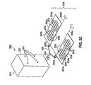
- FIGS 3A to 3C illustrate a spacecraft, in which three phased array assemblies are coupled to the same side of a spacecraft body by a single deployment couple and a single mounting platform.
- spacecraft 300 includes spacecraft body 301 with a side 302. Coupled to side 302 ( i.e ., here illustrated in a partially deployed position) of spacecraft body 302 by a deployment couple 304 is a phased array 3, which is made up of three phased array assemblies. Attached to deployment couple 304 is a mounting platform 305, to which the three phased array assemblies are coupled by 2-axis primary deployment gimbals 305a, 305b and 305c.
- spacecraft 300 is illustrated with phased array 303 in the next step of deployment, in which phased array assemblies 303a and 303b have been rotated by gimbals 305a and 305b, respectively, through 180° about axes 304a and 304b (which are parallel to an axis of deployment couple 304).
- spacecraft 300 is illustrated with phased array 300 in a fully-deployed state, with phased array assembly 303c having been rotated through 180° about axis 304c, which is parallel to an axis of deployment couple 304 ( e.g ., an axis defined at least in part by a direction in which a portion of deployment couple 304 is pointing).
Abstract
Description
- The present invention generally relates to the stowage and deployment of spacecraft elements and, in particular, relates to the stowage and deployment of multiple phased arrays or combinations of phased arrays and reflectors.
- One of the problems of stowing and deploying both phased arrays and antenna reflectors on the same spacecraft is the mass imbalance created by stowing an array on one side and a reflector on the other. If one side of a spacecraft contains reflectors and the other side phased arrays, the side-to-side center of gravity offset from the spacecraft center axis may lie well outside the limits prescribed by launch vehicle manuals. On-orbit control of the spacecraft may also become troublesome.
- Additional problems are encountered when multiple phased arrays or phased array assemblies are provided on a single spacecraft. The mass and size of the spacecraft makes it increasingly difficult to support, deploy, and steer. Moreover, in systems in which each phased array or phased array assembly is provided with its own launch restraint system or tie downs, the increased mass of the launch restraints and launch restraint severing systems will further impact the useful payload of the spacecraft.
DocumentEP 0 181 221 A2 discloses a folding antenna for use as part of a mobile earth station. The folding antenna is mounted on a base, which forms part of a container enclosing the reflector when in a stowed position. The folding antenna comprises two supporting members further comprising one arm supporting a main reflector and one arm pivoted to a collapsible stay, wherein the supporting members are further pivoted about an axis to a framework holding a feed horn. Furthermore, the framework holds a sub-reflector. One of the framework members is pivoted about an axis to the supporting members. The pivoting about the axis can be blocked by two pins. In order to collapse the folding antenna to the stowed position the pins have to be removed, whereby pivoting about axis is enabled. In the stowed position the framework rests on the base. The reflector is pivoted downwards about axis. Finally, two lids are closed, wherein the folding antenna is enclosed. The lids are held in their closed position by a catch mechanism. When unfolding the folding antenna to a deployed position, the pins have to be reintroduced in order to hold the folding antenna in the deployed position.
DocumentEP 1 189 301 A2 discloses a deployable antenna system for use on a spacecraft that is moveable from a stowed position to a deployed position. The antenna system includes one or two sets of main reflector assembly and subreflectors. The antenna system includes one or more feed horn assembly fixedly attached to the spacecraft and a rotatable hinge attached to the spacecraft. A substantially rigid reflector support structure is attached to the hinge and rotates about a hinge axis. The main reflector assembly is attached to a lower portion of the support structure and the subreflector is attached to an upper portion of the support structure.
DocumentUS 6 353 421 B1 discloses a deployable reflector for an electronically scanned reflector antenna. The deployable reflector may be confined to a relatively small volume for transportation of the reflector to a deployment site. Upon deployment, the reflector forms a relatively large reflector surface. The reflector generally includes a plurality of panel members interconnected to a plurality of ribs interconnected to an extendable boom.
DocumentEP 0 866 516 A1 discloses travelling wave tube amplifiers and multiplexers which are integrated onto electronically reconfigurable passive transmit array antenna panels deployed out board of a spacecraft bus to provide a spacecraft transponder, wherein the travelling wave tube amplifiers providing amplified RF signals to the multiplexers, the multiplexers being connected to the passive transmit array antenna transmiting the RF signals and radiating dissipated heat from the passive array antenna panels.
DocumentUS 2003/0 160 733 A1 discloses a space deployable antenna that includes an inflatable envelope, a cylindrical reflector formed on a wall of the envelope, a catenary support frame for maintaining the cylindrical shape of the cylindrical reflector, and a feed array support structure connected to the catenary support frame.
DocumentUS 6 504 514 B1 discloses a satellite antenna system employing a dual-band feed horn and dual-band beam forming network. The feed horn provides a common aperture for both satellite uplink and downlink communications signal.
The paper of Lier et al.: "Study of deployed and modular active phased-array multibeam satellite antenna" published in IEEE Antennas and propagation magazine, Vol. 45, No. 5, pages 34-45 discloses a deployed, self-cooled, and modular active phased array for multibeam applications.
Thus, according to an aspect, it is a problem provide a spacecraft having an enlarged useful payload. This problem is solved by a spacecraft having the features disclosed in claim 1. Preferred embodiments are defined in the dependent claims. - The present invention solves the foregoing problems by providing a stowage system that allows the packaging of one or more phased arrays and reflectors on the East and West sides of a spacecraft in order to distribute the mass of the spacecraft in a more symmetrical manner. This stowage system more efficiently uses the available volume in a launch vehicle and allows phased arrays and reflectors to have their own deployment, retention, and pointing systems, while requiring fewer common launch restraint systems.
- According to one embodiment of the present invention, a spacecraft comprises a spacecraft body as set out in claim 1.
- According to an example, a spacecraft comprises a spacecraft body, a first mounting platform coupled to a first side of the spacecraft body, a first deployment couple disposed between the first mounting platform and the first side of the spacecraft body and coupled to the first mounting platform and the first side of the spacecraft body, and a first plurality of phased array assemblies. Each of the first plurality of phased array assemblies has a face with a plurality of elements, and each of the first plurality of phased array assemblies is coupled to the first mounting platform by a gimbal. The spacecraft further comprises a first common launch restraint system configured to secure the first plurality of phased array assemblies to the first side of the spacecraft body using at least one common launch restraint mounting point. The first deployment couple and the first plurality of gimbals are configured to permit stowing the first plurality of phased array assemblies parallel to the first side of the spacecraft body and with the face of each of the first plurality of phased array assemblies oriented in a first direction.
- It is to be understood that both the foregoing summary of the invention and the following detailed description are exemplary and explanatory and are intended to provide further explanation of the invention as claimed.
- The accompanying drawings, which are included to provide further understanding of the invention and are incorporated in and constitute a part of this specification, illustrate embodiments of the invention and together with the description serve to explain the principles of the invention. In the drawings:
-
Figures 1A and 113 illustrate stowed and deployed states of a spacecraft; -
Figures 2A to 2D illustrate various states of stowage and deployment of a spacecraft; and -
Figures 3A to 3C illustrate stowed and deployed states of a spacecraft. - In the following detailed description, numerous specific details are set forth to provide a full understanding of the present invention. It will be apparent, however, to one ordinarily skilled in the art that the present invention may be practiced without some of these specific details. In other instances, well-known structures and techniques have not been shown in detail to avoid unnecessarily obscuring the present invention.
- Deployable phased arrays and launch restraint subsystems are designed to increase the flexibility, configurability and capability of modern satellites. In this regard, the stowed state is a state in which launch restraints are restraining the phased arrays or phased array assemblies in place for transport, and the deployment couples are in a volume-minimizing, retracted position. The deployed state is a state in which the launch restraints have been removed, and the phased arrays or phased array assemblies have been moved from the stowed position and oriented in their operational locations by fully articulating the deployment couples. A transitory deploying state in between the stowed state and the deployed state is also contemplated, but illustration of this state is not necessary for the purpose of understanding the features of the present invention.
-
Figure 1A illustrates a spacecraft , in which a reflector and a phased array are stowed with a common launch restraint mounting point on the same side of the spacecraft. Spacecraft 100 includesspacecraft body 101, which has aside 102. Coupled parallel toside 102 of spacecraft body 101 (i.e., in a stowed position) by adeployment couple 104 is aphased array 103.Phased array 103 has aface 103a on which are disposed a number ofelements 103b.Face 103a is oriented facing away fromside 102, to protectelements 103b from being damaged during launch byside 102. Also coupled parallel toside 102 ofspacecraft body 101 by anotherdeployment couple 106 is areflector 105. In the present exemplary embodiment,deployment couple 104 includes both a 1-axis hinge 104b and a 2-axisprimary deployment gimbal 104a, whiledeployment couple 106 includes a 2-axis gimbal 106a. Fourlaunch restraint locations 108 are provided inreflector 105 for securing reflector toside 102 ofspacecraft body 101 with a launch restraint system (not illustrated).Spacecraft 100 further includes anotherside 112opposite side 102, to which are coupled another phasedarray 110 and anotherreflector 111.Phased array 110 andreflector 111 are coupled toside 112 in a similar manner to that in which phasedarray 103 andreflector 105 are coupled toside 102. - Turning to
Figure 1B ,spacecraft 100 is illustrated withreflector 105 and phasedarray 103 in a deployed state. As can be seen with reference toFigure 1B , 2-axisprimary deployment gimbal 104a which permits phasedarray 103 to rotate about anaxis 104b ofdeployment couple 104.Primary deployment gimbal 104a permits phasedarray 103 to deploy with itsface 103a andelements 103b pointing up, by rotating phasedarray 103 through 180° aroundaxis 104b. As can also be seen with reference toFigure 1B ,deployment couple 106 includes a 2-axis gimbal 106a configured to permitreflector 105 to be deployed in the same plane as phasedarray 103, but with a different axis of orientation (e.g., by rotatingreflector 105 aroundaxis 106b). - In
Figure 1B , the common launchrestraint mounting points 107 whichreflector 105 and phasedarray 103 share can be seen onside 102 ofspacecraft body 101. Also visible are thelaunch restraint locations 109 provided in phasedarray 103 for securing phasedarray 103 toside 102 ofspacecraft body 101 using a launch restraint system. Using the enhanced antenna stowage and deployment system according to the embodiment of present invention illustrated inFigures 1A and 1B , the co-location and consolidation of launch restraints reduces the weight and volume ofspacecraft 100 by reducing the number of necessary launch restraints and launch restraint severing mechanisms, thereby increasing overall mission capabilities. - While
reflector 105 has been shown stowed on top of phasedarray 103, the scope of the present invention is not limited to such an arrangement. Rather, as will be apparent to one of skill in the art, the present invention has application to arrangements in which a phased array is stowed on top of a reflector, or arrangements in which reflectors and phased arrays are stacked in any order. - Similarly, while exactly four common launch
restraint mounting points 107 have been illustrated onside 102 ofspacecraft body 101, the scope of the present invention is not limited to such an arrangement. Rather, as will be apparent to one of skill in the art, the present invention has application to arrangements in which any number of common launch restraints greater than or equal to one are shared on a side of a spacecraft body. - Since the purpose of
deployment couples deployment couples deployment couple 104 may include only a single 1-taxis separating hinge, in order to effectively separate and deploy phasedarray 103 using a single 1-axis motion. In other arrangements,deployment couple 104 may include a single 2-axis primary deployment gimbal only, deploying and orienting phasedarray 103 in a more complex 2-axis motion. - Similarly, in further arrangements, deployment couples such as
couples - Turning to
Figure 2A , another spacecraft is illustrated , in which two phased array assemblies are coupled to the same side of a spacecraft body.Spacecraft 200 includesspacecraft body 201 with aside 202. Coupled parallel to side 202 (i.e., in the stowed position) ofspacecraft body 202 by adeployment couple 204 is a phasedarray 203, which is made up of phasedarray assemblies Deployment couple 204 includes 1-axis separating hinge 204b for separating phasedarray 203 fromspacecraft body 201. Coupled todeployment couple 204 is a mountingplatform 205, to which phasedarray assemblies primary deployment gimbals Assembly 203b has aface 203c on which are disposed a number ofelements 203d.Face 203c is oriented facing away fromside 202, to keepelements 203d from rubbing against the elements (not shown) ofassembly 203a. Fourlaunch restraint locations 209 are provided inreflector assembly 203b (and four inassembly 203a, not all of which are visible in this Figure) for mounting phasedarray 203 toside 202 ofspacecraft body 201, as is illustrated in greater detail with respect toFigure 2C , below. - Turning to
Figure 2B ,spacecraft 200 is seen in a first phase of deployment, in whichdeployment couple 204 has pivoted mountingplatform 205 and phasedarray 203 away fromside 202 ofspacecraft body 201. In this view, the common launchrestraint mounting points 207 whichassemblies side 202 ofspacecraft body 201. Also visible are additionallaunch restraint locations 209 inassembly 203a, the back side of which (i.e., the side without elements) is visible at this phase. - Turning next to
Figure 2C ,spacecraft 200 is seen an another phase of deployment, in whichprimary deployment gimbals assemblies assembly 203a has been rotated 180° counter-clockwise, whileassembly 203b has been rotated 180° in a clockwise direction. Visible in this Figure is theface 203e ofassembly 203a, on which are disposedelements 203f. As can be seen with reference toFigures 2A to 2C ,deployment couple 204, mountingplatform 205 andprimary deployment gimbals array assemblies faces side 202 of spacecraft body 201). -
Figure 2D illustratesspacecraft 200 enjoying yet another advantage of amounting system according to the present invention. As can be seen with reference toFigure 2D , mountingplatform 205 andprimary deployment gimbals array assemblies Figure 1B with respect toreflector 105 and phasedarray 103. 2-axisprimary deployment gimbal 205a is configured to rotate phasedarray assembly 203a over an angle of Φ2 such that the axis of orientation of phasedarray assembly 203a changes fromaxis 205c toaxis 205e. Similarly, 2-axisprimary deployment gimbal 205b is configured to rotate phasedarray assembly 203b over an angle of Φ1 such that the axis of orientation of phasedarray assembly 203b changes fromaxis 205d toaxis 205f. In this manner, phasedarray assemblies array assemblies - While the foregoing exemplary embodiment has been described with reference to the faces of multiple phased array assemblies all pointing away from the side of a spacecraft body when stowed, the scope of the present invention is not limited to such an arrangement. Rather, as will be apparent to one of skill in the art, the present invention has application to arrangements in which the faces of multiple phased array assemblies all point towards the side of a spacecraft body when stowed, or arrangements in which the faces of multiple phased array assemblies point in different directions when stowed.
- Similarly, while the foregoing exemplary embodiments have been described with reference to phased arrays and phased array assemblies having only one face with elements, the scope of the present invention is not limited to such an arrangement. Rather, as will be apparent to one of skill in the art, the present invention has application to arrangements in which phased arrays are provided with elements on more than one face.
- Moreover, while the foregoing exemplary embodiment has been described with reference to a single phased arrays mounted to a single side of a spacecraft body, the scope of the present invention is not limited to such an arrangement. Rather, as will be apparent to one of skill in the art, the present invention has application to arrangements in which multiple phased arrays are provided one more than one side of a spacecraft body.
-
Figures 3A to 3C illustrate a spacecraft, in which three phased array assemblies are coupled to the same side of a spacecraft body by a single deployment couple and a single mounting platform. Turning toFigure 3A ,spacecraft 300 includesspacecraft body 301 with aside 302. Coupled to side 302 (i.e., here illustrated in a partially deployed position) ofspacecraft body 302 by adeployment couple 304 is a phased array 3, which is made up of three phased array assemblies. Attached todeployment couple 304 is a mountingplatform 305, to which the three phased array assemblies are coupled by 2-axisprimary deployment gimbals - Turning to
Figure 3B ,spacecraft 300 is illustrated with phasedarray 303 in the next step of deployment, in which phasedarray assemblies gimbals axes Figure 3C ,spacecraft 300 is illustrated with phasedarray 300 in a fully-deployed state, with phasedarray assembly 303c having been rotated through 180° aboutaxis 304c, which is parallel to an axis of deployment couple 304 (e.g., an axis defined at least in part by a direction in which a portion ofdeployment couple 304 is pointing). - While the present invention has been particularly described with reference to the various figures and embodiments, it should be understood that these are for illustration purposes only and should not be taken as limiting the scope of the invention. There may be many other ways to implement the invention. Many changes and modifications may be made to the invention, by one having ordinary skill in the art.
Claims (8)
- A spacecraft (100) comprising:a spacecraft body (101);a first phased array (103) coupled to a first side (102) of the spacecraft body (101);a first reflector(105) coupled to the first side (102) of the spacecraft body (101);a first deployment couple (104) disposed between the first phased array (103) and the first side (102) of the spacecraft body (101) and coupled to the first phased array (103) and the first side (102) of the spacecraft body (101), the first deployment couple (104) configured to permit stowing the first phased array (103) parallel to the first side (102) of the spacecraft body (101);a second deployment couple (106) disposed between the first reflector (105) and the first side (102) of the spacecraft body (101) and coupled to the first reflector (105) and the first side (102) of the spacecraft body (101), the second deployment couple (106) configured to permit stowing the first reflector (105) parallel to the first side (102) of the spacecraft body (101); anda first common launch restraint system configured to secure the first phased array (103) and the first reflector (105) to the first side (102) of the spacecraft body (101) using at least one common launch restraint mounting point (107),characterized in that the first phased array (103) comprises a plurality of phased array assemblies, wherein each of the plurality of phased array assemblies are coupled to a mounting platform (205) by a gimbal, and wherein the mounting platform (205) is coupled to the first deployment couple (104).
- The spacecraft (100) of claim 1, wherein the first deployment couple (104) and the second deployment couple (106) are configured to permit stowing the first reflector (105) on top of the first phased array (103).
- The spacecraft (100) of claim 1, wherein the first phased array (103) and the first reflector (105) each include one or more launch restraint locations (108, 109) for securing the first phased array (103) and the first reflector (105) to the common launch restraint mounting point (107).
- The spacecraft (100) of claim 1, wherein the first phased array (103) has a face (103a) with a plurality of elements (103b), and wherein the first deployment couple (104) includes a primary gimbal (104a) configured to permit stowing the first phased array (103) parallel to the first side (102) of the spacecraft body (101) and with the face (103a) of the first phased array (103) oriented away from the first side (102) of the spacecraft body (101), and wherein the primary gimbal (104a) is configured to permit rotating the first phased array (103) around an axis of the first deployment couple (104) through an angle of at least 180°.
- The spacecraft (100) of claim 1, wherein each of the plurality of phased array assemblies has a face with a plurality of elements, and wherein the first deployment couple (104) and the gimbals of the plurality of phased array assemblies are configured to permit stowing the plurality of phased array assemblies parallel to the first side (102) of the spacecraft body (101) and with the face of each of the plurality of phased array assemblies oriented in a first
direction, and wherein at least one of the plurality of gimbals is configured to permit rotating an associated phased array assembly around an axis parallel to an axis of the first deployment couple (104) through an angle of at least 180°. - The spacecraft (100) of claim 1, wherein at least one of the plurality of gimbals is a 2-axis gimbal configured to permit deploying an associated phased array assembly in a same plane as another one of the plurality of phased array assemblies and with a different axis of orientation as the other one of the plurality of phased array assemblies.
- The spacecraft (100) of claim 1, wherein the second deployment couple (106) includes a 2-axis gimbal (106a) configured to permit deploying the first reflector (105) in a same plane as the first phased array (103) and with a different axis of orientation as the first phased array (103).
- The spacecraft (100) of claim 1, further comprising:a second phased array (110) coupled to a second side (112) of the spacecraft body (101) opposite the first side (102);a second reflector (111) coupled to the second side (112) of the spacecraft body (101);a third deployment couple disposed between the second phased array (110) and the second side (112) of the spacecraft body (101) and coupled to the second phased array (110) and the second side (112) of the spacecraft body (101), the third deployment couple configured to permit stowing the second phased array (110) parallel to the second side (112) of the spacecraft body (101);a fourth deployment couple disposed between the second reflector (111) and the second side (112) of the spacecraft body (101) and coupled to the second reflector (111) and the second side (112) of the spacecraft body (101), the fourth deployment couple configured to permit stowing the second reflector (111) parallel to the second side (112) of the spacecraft body (101); anda second common launch restraint system configured to secure the second phased array (110) and the second reflector (111) to the second side (112) of the spacecraft body (101) using a second at least one common launch restraint mounting point.
Applications Claiming Priority (3)
| Application Number | Priority Date | Filing Date | Title |
|---|---|---|---|
| US77620006P | 2006-02-24 | 2006-02-24 | |
| US11/653,912 US7602349B2 (en) | 2006-02-24 | 2007-01-17 | System of stowing and deploying multiple phased arrays or combinations of arrays and reflectors |
| PCT/US2007/003012 WO2007100447A2 (en) | 2006-02-24 | 2007-02-05 | System of stowing and deploying multiple phased arrays or combinations of arrays and reflectors |
Publications (3)
| Publication Number | Publication Date |
|---|---|
| EP1987604A2 EP1987604A2 (en) | 2008-11-05 |
| EP1987604A4 EP1987604A4 (en) | 2009-12-02 |
| EP1987604B1 true EP1987604B1 (en) | 2012-07-11 |
Family
ID=38443493
Family Applications (1)
| Application Number | Title | Priority Date | Filing Date |
|---|---|---|---|
| EP07749920A Expired - Fee Related EP1987604B1 (en) | 2006-02-24 | 2007-02-05 | System of stowing and deploying multiple phased arrays or combinations of arrays and reflectors |
Country Status (3)
| Country | Link |
|---|---|
| US (1) | US7602349B2 (en) |
| EP (1) | EP1987604B1 (en) |
| WO (1) | WO2007100447A2 (en) |
Families Citing this family (14)
| Publication number | Priority date | Publication date | Assignee | Title |
|---|---|---|---|---|
| EP2643882B1 (en) | 2010-12-15 | 2014-04-16 | Skybox Imaging, Inc. | Integrated antenna system for imaging microsatellites |
| US8800935B2 (en) * | 2011-03-09 | 2014-08-12 | Space Systems/Loral, Llc | Spacecraft payload positioning with respect to a virtual pivot point |
| US9004409B1 (en) * | 2011-08-23 | 2015-04-14 | Space Systems/Loral, Llc | Extendable antenna reflector deployment techniques |
| US9248922B1 (en) * | 2011-08-23 | 2016-02-02 | Space Systems/Loral, Llc | Reflector deployment techniques for satellites |
| US10773833B1 (en) | 2011-08-30 | 2020-09-15 | MMA Design, LLC | Panel for use in a deployable and cantilevered solar array structure |
| US10263316B2 (en) | 2013-09-06 | 2019-04-16 | MMA Design, LLC | Deployable reflectarray antenna structure |
| US10270524B2 (en) | 2014-04-15 | 2019-04-23 | Space Systems/Loral, Llc | Broadband satellite payload architecture |
| US9878806B2 (en) | 2015-03-09 | 2018-01-30 | Space Systems/Loral, Llc | On-orbit assembly of communication satellites |
| CA2999987C (en) | 2015-09-25 | 2023-09-05 | M.M.A. Design, LLC | Deployable structure for use in establishing a reflectarray antenna |
| US10259599B2 (en) * | 2015-12-08 | 2019-04-16 | Space Systems/Loral, Llc | Spacecraft with rigid antenna reflector deployed via linear extension boom |
| FR3060867B1 (en) | 2016-12-20 | 2019-05-17 | Thales | DEPLOYABLE SOURCE BLOCK ARCHITECTURE, COMPACT AND SATELLITE ANTENNA COMPRISING SUCH AN ARCHITECTURE |
| US10177460B2 (en) | 2017-04-24 | 2019-01-08 | Blue Digs LLC | Satellite array architecture |
| US11724828B2 (en) | 2019-01-18 | 2023-08-15 | M.M.A. Design, LLC | Deployable system with flexible membrane |
| WO2023044162A1 (en) * | 2021-09-20 | 2023-03-23 | WildStar, LLC | Satellite and antenna therefor |
Family Cites Families (15)
| Publication number | Priority date | Publication date | Assignee | Title |
|---|---|---|---|---|
| US3699581A (en) | 1970-06-25 | 1972-10-17 | Trw Inc | Large area deployable spacecraft antenna |
| US4771293A (en) * | 1984-11-07 | 1988-09-13 | The General Electric Company P.L.C. | Dual reflector folding antenna |
| US5520747A (en) | 1994-05-02 | 1996-05-28 | Astro Aerospace Corporation | Foldable low concentration solar array |
| US6037909A (en) | 1997-03-21 | 2000-03-14 | Space Systems/Loral, Inc. | Deployed payload for a communications spacecraft |
| US6124835A (en) | 1999-07-01 | 2000-09-26 | Trw Inc. | Deployment of dual reflector systems |
| US6353421B1 (en) * | 2000-09-14 | 2002-03-05 | Ball Aerospace And Technologies Corp. | Deployment of an ellectronically scanned reflector |
| US6366255B1 (en) | 2000-09-15 | 2002-04-02 | Space Systems/Loral, Inc. | Main reflector and subreflector deployment and storage systems |
| US6448940B1 (en) * | 2001-03-20 | 2002-09-10 | Space Systems/Loral, Inc. | Triple reflector antenna deployment and storage systems |
| US6504514B1 (en) * | 2001-08-28 | 2003-01-07 | Trw Inc. | Dual-band equal-beam reflector antenna system |
| FR2834274B1 (en) | 2002-01-02 | 2004-04-02 | Astrium Sas | SPACE VEHICLE WITH DEPLOYABLE RADIATORS |
| US6650304B2 (en) | 2002-02-28 | 2003-11-18 | Raytheon Company | Inflatable reflector antenna for space based radars |
| US7000883B2 (en) | 2003-01-17 | 2006-02-21 | The Insitu Group, Inc. | Method and apparatus for stabilizing payloads, including airborne cameras |
| US6859188B1 (en) | 2003-03-27 | 2005-02-22 | Lockheed Martin Corporation | Rotationally configurable offset reflector antenna |
| US6999036B2 (en) | 2004-01-07 | 2006-02-14 | Raysat Cyprus Limited | Mobile antenna system for satellite communications |
| US7180470B1 (en) * | 2004-12-03 | 2007-02-20 | Lockheed Martin Corporation | Enhanced antenna stowage and deployment system |
-
2007
- 2007-01-17 US US11/653,912 patent/US7602349B2/en active Active
- 2007-02-05 WO PCT/US2007/003012 patent/WO2007100447A2/en active Application Filing
- 2007-02-05 EP EP07749920A patent/EP1987604B1/en not_active Expired - Fee Related
Also Published As
| Publication number | Publication date |
|---|---|
| US7602349B2 (en) | 2009-10-13 |
| US20070200780A1 (en) | 2007-08-30 |
| EP1987604A4 (en) | 2009-12-02 |
| WO2007100447A3 (en) | 2008-01-17 |
| WO2007100447A2 (en) | 2007-09-07 |
| EP1987604A2 (en) | 2008-11-05 |
Similar Documents
| Publication | Publication Date | Title |
|---|---|---|
| EP1987604B1 (en) | System of stowing and deploying multiple phased arrays or combinations of arrays and reflectors | |
| US11677133B2 (en) | Deployable structure for use in establishing a reflectarray antenna | |
| US7598922B2 (en) | Deployable booms | |
| JP6858649B2 (en) | Laminated pancake type satellite | |
| CA2451724C (en) | Inflatable reflector antenna for space based radars | |
| US6963315B2 (en) | Inflatable antenna | |
| US20190280364A1 (en) | Deployable Reflectarray Antenna Structure | |
| JP6419180B2 (en) | Parallel dual launch mechanism | |
| US6448940B1 (en) | Triple reflector antenna deployment and storage systems | |
| US9248922B1 (en) | Reflector deployment techniques for satellites | |
| US6366255B1 (en) | Main reflector and subreflector deployment and storage systems | |
| US20170021948A1 (en) | Space vehicle | |
| US6124835A (en) | Deployment of dual reflector systems | |
| JP4876941B2 (en) | Deployable antenna | |
| CN1321860C (en) | Space craft with extensible radiators | |
| EP4024606B1 (en) | Deployable assembly for antennae | |
| US7180470B1 (en) | Enhanced antenna stowage and deployment system | |
| US10461432B1 (en) | Collapsible feed structures for reflector antennas | |
| US7548218B2 (en) | Isostatic support structure or fixed or re-orientable large size antenna reflectors | |
| JPH068120B2 (en) | Geostationary communication satellite | |
| Huang et al. | Spacecraft antenna research and development activities aimed at future missions | |
| RU2795105C1 (en) | Deployable antenna assembly | |
| JPH06244631A (en) | Antenna module for space |
Legal Events
| Date | Code | Title | Description |
|---|---|---|---|
| PUAI | Public reference made under article 153(3) epc to a published international application that has entered the european phase |
Free format text: ORIGINAL CODE: 0009012 |
|
| 17P | Request for examination filed |
Effective date: 20080801 |
|
| AK | Designated contracting states |
Kind code of ref document: A2 Designated state(s): FR |
|
| RBV | Designated contracting states (corrected) |
Designated state(s): FR |
|
| A4 | Supplementary search report drawn up and despatched |
Effective date: 20091102 |
|
| RIC1 | Information provided on ipc code assigned before grant |
Ipc: H01Q 1/28 20060101ALI20091027BHEP Ipc: H04B 7/185 20060101AFI20080807BHEP |
|
| 17Q | First examination report despatched |
Effective date: 20100210 |
|
| GRAP | Despatch of communication of intention to grant a patent |
Free format text: ORIGINAL CODE: EPIDOSNIGR1 |
|
| RIC1 | Information provided on ipc code assigned before grant |
Ipc: H01Q 1/28 20060101ALI20111229BHEP Ipc: H01Q 21/06 20060101ALI20111229BHEP Ipc: H01Q 1/12 20060101AFI20111229BHEP Ipc: H01Q 3/08 20060101ALI20111229BHEP Ipc: H01Q 19/12 20060101ALI20111229BHEP |
|
| DAX | Request for extension of the european patent (deleted) | ||
| GRAS | Grant fee paid |
Free format text: ORIGINAL CODE: EPIDOSNIGR3 |
|
| GRAA | (expected) grant |
Free format text: ORIGINAL CODE: 0009210 |
|
| AK | Designated contracting states |
Kind code of ref document: B1 Designated state(s): FR |
|
| PLBE | No opposition filed within time limit |
Free format text: ORIGINAL CODE: 0009261 |
|
| STAA | Information on the status of an ep patent application or granted ep patent |
Free format text: STATUS: NO OPPOSITION FILED WITHIN TIME LIMIT |
|
| 26N | No opposition filed |
Effective date: 20130412 |
|
| REG | Reference to a national code |
Ref country code: FR Ref legal event code: PLFP Year of fee payment: 10 |
|
| REG | Reference to a national code |
Ref country code: FR Ref legal event code: PLFP Year of fee payment: 11 |
|
| PGFP | Annual fee paid to national office [announced via postgrant information from national office to epo] |
Ref country code: FR Payment date: 20170223 Year of fee payment: 11 |
|
| REG | Reference to a national code |
Ref country code: FR Ref legal event code: ST Effective date: 20181031 |
|
| PG25 | Lapsed in a contracting state [announced via postgrant information from national office to epo] |
Ref country code: FR Free format text: LAPSE BECAUSE OF NON-PAYMENT OF DUE FEES Effective date: 20180228 |