EP3059800B1 - Deployable reflectarray antenna structure - Google Patents
Deployable reflectarray antenna structure Download PDFInfo
- Publication number
- EP3059800B1 EP3059800B1 EP16155768.1A EP16155768A EP3059800B1 EP 3059800 B1 EP3059800 B1 EP 3059800B1 EP 16155768 A EP16155768 A EP 16155768A EP 3059800 B1 EP3059800 B1 EP 3059800B1
- Authority
- EP
- European Patent Office
- Prior art keywords
- tapes
- electrical element
- tape
- reflectarray antenna
- antenna structure
- Prior art date
- Legal status (The legal status is an assumption and is not a legal conclusion. Google has not performed a legal analysis and makes no representation as to the accuracy of the status listed.)
- Active
Links
Images


Classifications
-
- H—ELECTRICITY
- H01—ELECTRIC ELEMENTS
- H01Q—ANTENNAS, i.e. RADIO AERIALS
- H01Q1/00—Details of, or arrangements associated with, antennas
- H01Q1/27—Adaptation for use in or on movable bodies
- H01Q1/28—Adaptation for use in or on aircraft, missiles, satellites, or balloons
- H01Q1/288—Satellite antennas
-
- H—ELECTRICITY
- H01—ELECTRIC ELEMENTS
- H01Q—ANTENNAS, i.e. RADIO AERIALS
- H01Q1/00—Details of, or arrangements associated with, antennas
- H01Q1/08—Means for collapsing antennas or parts thereof
-
- H—ELECTRICITY
- H01—ELECTRIC ELEMENTS
- H01Q—ANTENNAS, i.e. RADIO AERIALS
- H01Q15/00—Devices for reflection, refraction, diffraction or polarisation of waves radiated from an antenna, e.g. quasi-optical devices
- H01Q15/14—Reflecting surfaces; Equivalent structures
- H01Q15/148—Reflecting surfaces; Equivalent structures with means for varying the reflecting properties
Definitions
- the electric motors 204, 244 are capable of being used so as to control the rate at which the tapes 320A-320D and 322A-322D are deployed. As such, the electric motors 204, 244 each function, at least in part, as dampers to control the transition of the tape between the undeployed and deployed states. Note that the motors can be controlled so that not all of the tape beyond the fixed first terminal end is extended from its cartridge. Some tape may be retained on the axle to facilitate damping.
Description
- The invention relates to a deployable antenna structure and, more specifically, to a deployable reflectarray antenna structure.
- In applications requiring a high-gain antenna, there are at least three types of antennas that are typically employed, namely, a parabolic antenna, phased-array antenna, and a reflectarray antenna. The basic parabolic antenna includes a parabolic shaped reflector and a feed antenna located at the focus of the paraboloid and directed towards the reflector. The phased-array antenna includes multiple antennas with a feed network that provides a common signal to each of the antennas but with the relative phase of the common signal being fed to each of the antennas established such that the collective radiation pattern produced by the array of antennas is reinforced in one direction and suppressed in other directions, i.e., the beam is highly directional. In many applications, the phased-array antenna is preferred to the parabolic antenna because a phased-array antenna can be realized with a lower height profile relative to the parabolic antenna. However, the phased-array antenna typically requires a complicated and/or expensive feed network and amplifier structures. The basic reflectarray antenna includes a reflectarray that is flat or somewhat curved and a feed antenna directed towards the reflectarray. The reflectarray includes an array of radiating elements that each receive a signal from the feed antenna and reradiate the signal. Each of the radiating elements has a phase delay such that the collective reradiated signal produced by the array of radiating elements is in a desired direction. Importantly, the radiating elements are fed by the feed antenna. As such, relative to the phased-arrayed antenna, the reflectarray avoids the need for a feed network to provide a signal to each of the radiating elements.
- An application that frequently requires a high-gain antenna is a space-related application in which the antenna is associated with a spacecraft, e.g., a communication satellite. Such space-related applications typically impose an additional requirement of deployability on the design of a high-gain antenna, i.e., the antenna needs to be able to transition from a stowed/undeployed state in which the antenna is inoperable or marginally operable to unstowed/deployed state in which the antenna is operable. As such, the high-gain antenna in these applications is coupled with a deployment mechanism that is used to transition the antenna from the stowed/undeployed state to the unstowed/deployed state. Characteristic of many space-related applications for such antennas is that the antenna and deployment mechanism occupy a small volume in the undeployed state relative to the volume occupied by the antenna and deployment mechanism in the deployed state.
- One approach for realizing a deployable high-gain antenna suitable for use on a spacecraft is a parabolic antenna structure that includes a wire mesh reflector, a feed antenna, and a deployment mechanism. The deployment mechanism operates to transition: (a) the wire mesh reflector from a stowed state in which the reflector is folded to an unstowed state in which the reflector is supported in a paraboloid-like shape by a frame associated with the deployment mechanism and (b) the wire mesh reflector and the feed antenna from an inoperable stowed state in which the wire mesh reflector and feed antenna are not operably positioned relative to one another to an unstowed state in which the wire mesh reflector and feed antenna are operatively positioned relative to one another. Characteristic of such deployable parabolic antenna structures is a high part count and the need for a relatively large volume to accommodate the stowed wire mesh reflector, feed antenna, and deployment mechanism. Document
US 2014/0263844 A1 describes such a deployable reflectarray antenna. - A second approach for realizing a deployable high-gain antenna suitable for use on a spacecraft is a reflectarray antenna structure that includes a two-layer reflectarray membrane, a feed antenna, and an inflatable deployment mechanism. The inflatable deployment mechanism operates to transition: (a) the reflectarray membrane from a stowed state in which the membrane is folded to an unstowed state in which the inflated deployment mechanism forms a frame that is used in tensioning the reflectarray membrane into a flat shape, similar to trampoline and (b) the reflectarray membrane and the feed antenna from an inoperable stowed state in which the reflectarray membrane and feed antenna are not operably positioned with respect to one another to an unstowed state in which the reflectarray membrane and the feed antenna are operably positioned relative to one another. Characteristic of such a deployable reflectarray are difficulties in understanding the deployment kinematics and reliability challenges, particularly in space-based applications.
- A deployable reflectarray antenna structure is provided that is suitable for use in applications in which elements that are used to form the reflectarray antenna structure need to transition from an undeployed state in which the elements conform to a particular volume in which the elements are not situated so as to function in a reflectarray antenna structure to a deployed state in which the elements are situated so as to function in a reflectarray antenna structure. One such application for a deployable reflectarray antenna structure is as part of a space vehicle, (e.g., a communication satellite) in which elements of the structure typically need to conform to a compact or dimensionally constrained volume for at least a portion of the launch of the space vehicle and then be deployed from the compact or dimensionally constrained space so as to form a reflectarray antenna structure that typically occupies a considerably greater volume.
- In one embodiment, the deployable reflectarray antenna structure includes a pair of electrical elements and a deployment mechanism for transitioning the pair of electrical elements from an undeployed state in which the electrical elements are not positioned relative to one another to function in a reflectarray antenna towards a deployed state in which the electrical elements are positioned relative to one another to function in a reflectarray antenna. To facilitate the transition of the electrical elements from the undeployed state towards the deployed state, a tape is employed in which one end of the tape is operatively connected to one of the electrical elements. In operation, the tape transitions from undeployed state in which the ends of the tape are relatively close to one another to a deployed state in which the ends of the tape are farther from one another than in the undeployed state. In performing this transition, the end of the tape that is operatively connected to one of the pair of electrical elements facilitates the positioning of the electrical element for use in a reflectarray antenna. To control the transition of the tape between the undeployed and deployed states, the deployment mechanism employs a damper. In a particular embodiment, one of the pair of electrical elements and the deployment mechanism cooperate to establish a reflectarray in a deployed Cassegrain/Gregorian-type reflectarray antenna structure. The other of the pair of electrical elements and the deployment mechanism cooperate to establish a subreflector in the deployed Cassegrain/Gregorian-type reflectarray antenna structure.
- In another embodiment, the deployable reflectarray antenna structure includes a pair of electrical elements and a deployment mechanism that employs multiple tapes in transitioning the two electrical elements from an undeployed state towards a deployed state. In the undeployed state, neither of the two electrical elements functions as an element of a reflectarray antenna system. In the deployed state, the two electrical elements and the deployment mechanism cooperate to form two elements of a reflectarray antenna structure. Further, the deployment mechanism functions in the deployed state to establish the necessary positional relationships of the two elements for functioning in a reflectarray antenna structure.
- In one embodiment, multiple tapes in the deployed state cooperate with one of the pair of electrical elements to form an element of a reflectarray antenna structure. In this regard, the multiple deployed tapes define a solid shape. In a particular embodiment, the first ends of four tapes define one base of a frustum of a pyramid-like structure, the second ends of the four tapes define the other base of the frustum of a pyramid-like structure, and the substantial portions of the four tapes that are linearly disposed between the first and second ends define the edges of the frustum of a pyramid-like structure.
- In another embodiment, multiple tapes in the deployed state form support structures. In a particular embodiment, the first ends of three tapes define one base of a frustum of a tetrahedron-like structure (i.e., a particular type of pyramid), the second ends of the three tapes define the other base of the frustum of a tetrahedron-like structure, and the substantial portions of the three tapes that are linearly disposed between the first and second ends define the edges of the frustum of the tetrahedron-like structure. In yet another embodiment, four tapes in the deployed state define a portion of a queen post like truss. In this regard, two of the deployed tapes form a substantial portion of the tie beam of the queen post like truss and the other two of the deployed tapes form the queen posts of the queen post like truss.
- Yet another embodiment of the deployable reflectarray antenna structure includes a pair of flexible electrical elements, a feed antenna, and a deployment mechanism that includes a deployable frame structure. The deployable reflectarray antenna structure also includes a canister that defines an enclosed space for storing the flexible electrical elements, feed antenna, and deployment mechanism, when each such component of the structure is in an undeployed state. The canister includes a door or hatch that, when opened, allows the flexible electrical elements, feed antenna, and deployment mechanism to operate so that the deployable frame structure and pair of flexible electrical elements cooperate to produce a reflectarray and a subreflector of a Cassegrain/Gregorian-type reflectarray antenna with the reflectarray and subreflector appropriately positioned relative to the feed antenna for a Cassegrain/Gregorian-type reflectarray antenna. When the pair of flexible elements, feed antenna, and deployment mechanism are undeployed and situated within the canister, the deployable frame mechanism is located between the pair of flexible electrical elements.
-
-
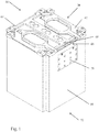
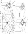
FIG. 1 illustrates an embodiment of the deployable reflectarray antenna structure in an undeployed state; -
FIG. 2 is a cross-sectional view of the deployable reflectarray antenna structure shown inFIG. 1 in the undeployed state; -
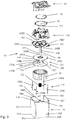
FIG. 3 is an exploded view of the deployable reflectarray antenna structure shown inFIG. 1 in the undeployed state; -
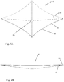
FIGS. 4A and 4B respectively are a perspective view and side view of the reflectarray of the deployable reflectarray antenna shown inFIG. 1 ; -
FIG. 5 is a perspective view of the subreflector of the deployable reflectarray antenna shown inFIG. 1 ; -
FIG. 6 is a perspective view of the primary tape dispenser for transitioning a flexible membrane from an undeployed state towards a deployed state in which the flexible membrane is configured for use as the reflectarray illustrated inFigs. 4A and 4B ; -
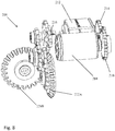
FIG. 7 is a perspective view of the motor and transmission system associated with the primary tape dispenser shown inFIG. 6 ; -
FIG. 8 is a perspective view of the motor and drive train associated with the primary tape dispenser shown inFIGS. 6 and7 ; -
FIG. 9 is a perspective view of the secondary tape dispenser for transitioning a flexible membrane from an undeployed state towards a deployed state in which the flexible membrane is configured for use as the subreflector shown inFIG. 5 ; -
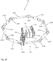
FIG. 10 is a perspective view of the motor and transmission system associated with the secondary tape dispenser shown inFIG. 9 ; -
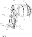
FIG. 11 is a perspective view of the motor and drive train associated with the secondary tape dispenser shown inFIGS. 9 and10 ; -
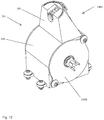
FIG. 12 is a perspective view of a tape cartridge or dispenser used in the secondary tape dispenser shown inFIGS. 9-11 ; -
FIG. 13 is an exploded view of the tape dispenser shown inFIG. 12 ; -
FIG. 14 is a cross-sectional view of the tape dispenser shown inFIG. 12 ; -
FIG. 15 illustrates the tape associated with the tape dispenser shown inFIG. 12 in its deployed state; -
FIG. 16 illustrates the connection structure used to establish a connection between a membrane, a pair of lanyards, and a tape; -
FIGS. 17A-17C illustrate the method of folding the first flexible electrical element to place in the element in an undeployed state; and -
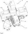
FIGS. 18A-18D illustrate the transition of the deployable reflectarray antenna structure shown in the foregoing figures from the undeployed state to the deployed state. - With reference to
Figs. 1-5 and18A-18D , an embodiment of a deployable reflectarray antenna structure 20 (hereinafter referred to as "thedeployable reflectarray 20") is described. Thedeployable reflectarray 20 conforms to the CubeSat design specification. More specifically, thedeployable reflectarray 20 conforms to a 1U CubeSat design specification, which requires thedeployable reflectarray 20 be embodied within a cube that is 10 cm on a side and has a mass of no more than 1.33 kg. Although thedeployable reflectarray 20 conforms to the CubeSat 1U design specification, it should be appreciated that adaptation to other form factors and mass requirements is feasible. - The
deployable reflectarray 20 includes acanister 22, afeed antenna 24, a first flexibleelectrical element 26, a second flexibleelectrical element 28, and adeployment mechanism 30. Generally, thecanister 22 stores thefeed antenna 24, first and second flexibleelectrical elements deployment mechanism 30 in an undeployed state and provides a base for supporting thefeed antenna 24, first and secondflexible elements deployment mechanism 30 in the deployed state. In the undeployed state, thefeed antenna 24 is disposed within a particular volume within thecanister 22. Additionally, the first and second flexibleelectrical elements canister 22. In the deployed state, thefeed antenna 24 and the first and second flexibleelectrical elements deployment mechanism 30 respectively supports the first flexibleelectrical element 26 so as to form aprimary reflectarray 40 and the second flexibleelectrical element 28 so as to form a secondary reflectarray 42 (reflectarray subreflector) in the configuration. Further, thedeployment mechanism 30 positions thefeed antenna 24,primary reflectarray 40, andsecondary reflectarray 42 relative to one another to realize the noted configuration. In this regard, thefeed antenna 24,primary reflectarray 40, andsecondary reflectarray 42 are disposed along a center-line 44. - With reference to
Figs. 1 and2 , thecanister 22 generally is comprised of atubular side surface 50, abottom surface 52 that extends across one end of thetubular side surface 50, anddoor structure 54 that extends across the other end of thetubular side surface 50. Thetubular side surface 50 includes four planar side surfaces 56A-56D and four inside corner surfaces 58A-58D that each engages the lateral edges of two adjacent planar side surfaces. Each of the inside corner surfaces accommodates a square rod (not shown) that is part of the CubeSat design specification. Thebottom surface 52 is planar and defines at least one hole orpassageway 60 that accommodates a coaxial cable (not shown) which allows electrical signals to be communicated to and/or from thefeed antenna 24. Thedoor structure 54 includes a first hingeddoor 62 that is spring-biased towards an open position and a second hingeddoor 64 that is also spring-biased towards an open position. Associated with thedoor structure 54 is alatch mechanism 66 that holds the first and second hingeddoors doors latch mechanism 66 includes ameltable pin 68 that engages the second hingeddoor 64 to hold the doors in the closed/undeployed state. Associated with thecanister 22 is acontrol board 70 that is used to apply an electrical current to themeltable pin 68 via wires (not shown) that causes the pin to melt so that the first and second hingeddoors - The
feed antenna 24 is an antenna that is capable of feeding thesecondary reflectarray 42 when the deployablereflectarray antenna structure 20 is in the deployed state. In the illustrated embodiment, thefeed antenna 24 is a low-profile phased array antenna. In other embodiments, a horn antenna is employed for the feed antenna. - With reference to
Figs. 4A and 4B , the first flexibleelectrical element 26 is comprised of (a) a firstflexible membrane 80 that supports an array of reflectarray elements and (b) a secondflexible membrane 82 that serves as a ground plane in the deployed state. A compressible and flexible dielectric structure is located between the first and second flexible membranes and operates to maintain a desired spacing between the first and second flexible membranes when the first flexibleelectrical element 26 is deployed as theprimary reflectarray 40. Generally, the first flexibleelectrical element 26 has anouter edge 86 that defines a substantially square shape with catenary-shaped edges when the element is in the deployed state. Theflexible element 26 also has aninner edge 88 that defines a hole which accommodates a portion of thedeployment mechanism 30. The flexible characteristics of the first and secondflexible membranes electrical element 26 to be folded so as to fit within a specified volume within thecanister 22 when the element is in the undeployed state. When the first flexibleelectrical element 26 is in the deployed state, i.e., forming theprimary reflectarray 40, the first flexibleelectrical element 26 generally defines a frustum of a pyramid in which theouter edge 86 defines a substantially square base of a pyramid-like structure and the inner edge defines a flattened apex of the pyramid-like structure. In other embodiments, the first flexible electrical element in the deployed state is in the form of: a substantially flat square. It should be appreciated that the first flexible electrical element is not limited to having an outer edge that takes on a square shape when the element is in the deployed state. For example, other polygon shapes (e.g., triangles), curved shapes (e.g., circles), and shapes comprised of curved and straight sections are feasible. In the case of thedeployable reflectarray 20, the square characteristic of theouter edge 86 of the first flexibleelectrical element 26 substantially conforms to the square/cubic nature of thecanister 22. Other applications may more naturally lend themselves to a first flexible electrical element having a different deployed shape. For instance, a cylindrical volume for storing a first flexible electrical element may suggest an element with an outer edge that is circular in the deployed state. - With reference to
Fig. 5 , the second flexibleelectrical element 28 is comprised of (a) a firstflexible membrane 90 that supports an array of reflectarray elements and (b) a secondflexible membrane 92 that serves as a ground plane in the deployed state. A compressible and flexible dielectric structure is located between the first and second flexible membranes and operates to maintain a desired spacing between the first and second flexible membranes when the second flexibleelectrical element 28 is deployed as thesecondary reflectarray 42. Generally, the second flexibleelectrical element 28 has anouter edge 96 that defines a substantially square shape with catenary-shaped edges when the element is in the deployed state. Theflexible element 28 also has aninner edge 98 that defines a hole. The flexible characteristics of the first and secondflexible membranes electrical element 28 to be folded so as to fit within a specified volume of thecanister 22 when the element is in the undeployed state. When the second flexibleelectrical element 28 is in the deployed state, i.e., forming thesecondary reflectarray 42, the second flexibleelectrical element 28 is generally planar and theouter edge 96 generally defines a square. It should be appreciated that the second flexible electrical element is not limited to having an outer edge that takes on a square shape when the element is in the deployed state. For example, other polygon shapes (e.g., triangles), curved shapes (e.g., circles), and shapes comprised of curved and straight sections are feasible. Additionally, in other embodiments, the second flexible electrical element can be a reflector or polarizer, as opposed to a reflectarray subreflector. - With reference to
Figs. 2 and3 , thedeployment mechanism 30 operates to transition thedeployable reflectarray 20 between an undeployed state and a deployed state. In the undeployed state, thefeed antenna 24, first flexibleelectrical element 26, second flexibleelectrical element 28, and thedeployment mechanism 30 are disposed within the enclosed space defined by thecanister 22 when the first and second hingeddoors electrical elements secondary reflectarrays feed antenna 24,primary reflectarray 40, andsecondary reflectarray 42 are located with respect to one another so as to implement a center-fed Cassegrain/Crregorian-style reflectarray antenna. - The
deployment mechanism 30 transitions thedeployable reflectarray 20 between the undeployed and deployed states in two phases. In the first phase, the first and second flexibleelectrical elements secondary reflectarrays feed antenna 24 to establish the center-fed Cassegrain/Gregorian-style reflectarray antenna. The second phase involves the deployment of the first and secondelectrical elements secondary reflectarrays feed antenna 24 to establish the reflectarray antenna. - Generally, the
deployment mechanism 30 includes aguide tube structure 110, aspring 112, alimit lanyard system 114, aprimary housing 116, abase plate 118, atape dispenser 120, and asecondary housing 122. - The
guide tube structure 110 serves a number of purposes. To elaborate, theguide tube structure 110 directs the displacement of theprimary housing 116 with the undeployed first flexibleelectrical element 26 supported by the housing, thebase plate 118, thetape dispenser 120, thefeed antenna 24, thesecondary housing 122 with the undeployed second flexibleelectrical element 28 during the first phase of the transition of thedeployable reflectarray 20 between the undeployed and deployed states. Theguide tube structure 110 also operates so as to prevent thebase plate 118,tape dispenser 120,feed antenna 24, andsecondary housing 122 from rotating relative to thecanister 122 during the transition and thereafter. Additionally, theguide tube structure 110 provides an axle about which theprimary housing 116 can rotate during the second phase of the transition. Theguide tube structure 110 also defines a portion of thepassageway 60 that accommodates the coaxial cable or other signal transmission structure that is capable of providing electrical signals to and/or from thefeed antenna 24. - The
guide tube structure 110 includes a ridgedcylindrical guide tube 130 with afirst end 132 fixedly attached to thebottom surface 52 of thecanister 22 and afree end 134. Additionally, the ridgedcylindrical guide tube 130 defines alongitudinally extending ridge 136. - The guide tube structure also includes a slotted
cylindrical guide tube 140 with afirst end 142 fixedly attached to thebase plate 118, afree end 144, and aslot 146 that is dimensioned to engage theridge 136 associated with ridgedcylindrical guide tube 130. The inner diameter of the slotted guide tube 140 (excluding the ridge 146) is slightly greater than the outer diameter of the ridgedcylindrical guide tube 130. As such, the slottedguide tube 140 is capable of sliding over the ridgedguide tube 130 when the tubes are oriented so that theslot 146 engages theridge 136. In the first phase of the transition between the undeployed and deployed states, the slottedguide tube 140 can be extended away from the ridgedguide tube 130 to direct theprimary housing 116 and other elements outside of thecanister 22. The "keying" of theslot 146 and theridge 136 prevents rotation of thebase plate 118 and other elements supported by the base plate during the transition and thereafter. - The
spring 112 provides the energy for moving theprimary housing 116 with the undeployed first flexibleelectrical element 26 supported by the primary housing, thebase plate 118, thetape dispenser 120, thefeed antenna 24, thesecond housing 122 with the undeployed second flexibleelectrical element 28 during the first phase of the transition of thedeployable reflectarray 20 between the undeployed and deployed states. Thespring 112 extends between the interior side of thebottom surface 52 of the canister and theprimary housing 116. When thedeployable reflectarray 20 is in the undeployed state with the first andsecond doors canister 22 closed, thespring 112 is compressed. After the first andsecond doors spring 112 is released and a force is applied to theprimary housing 116 with the undeployed first flexibleelectrical element 26 supported by the housing, thebase plate 118, thetape dispenser 120, thefeed antenna 24, thesecond housing 122 with the undeployed second flexibleelectrical element 28 as directed by theguide tube structure 110 so that these elements are positioned for the second phase of the transition between the undeployed and deployed states. In the illustrated embodiment, thespring 112 provides sufficient energy so that theprimary housing 116 and the first flexibleelectrical element 26 and thesecondary housing 122 and the second flexibleelectrical element 28 are sufficiently exposed for the second phase of the transition between the undeployed and deployed state. In this regard, thespring 112 provides sufficient energy to position the bottom of theprimary housing 116 at or slightly above the edge of thecanister 22 that is exposed following the opening of the first andsecond doors - The
limit lanyard system 114 operates to limit the extent to which thespring 112 moves theprimary housing 116 with the undeployed first flexibleelectrical element 26 supported by the housing, thebase plate 118, thetape dispenser 120, thefeed antenna 24, thesecond housing 122 with the undeployed second flexibleelectrical element 28 along theguide tube structure 110 during the first phase of the transition between the undeployed and deployed states. To elaborate, thespring 112 is designed to provide sufficient energy to move the noted elements to a desired position for the second phase of the transition. To ensure that the elements reach the desired position, thespring 112 is designed so as to be capable of providing more energy than is needed to position the elements at the desired position. As such, thespring 112 is potentially capable of moving the elements beyond the desired position. Thelimit lanyard system 114 prevents thespring 112 from moving the elements beyond the desired position. The limit lanyard system includeslanyards 150A-150D, each with one end connected to thebottom surface 52 of thecanister 22 and the other end connect to thebase plate 118. The length of each of thelanyards 150A-150D is chosen so that when the lanyard is fully extended due to the force being provided by thespring 112, the elements are at the desired position for the second phase of the transition. - The
primary housing 116 serves to define, in combination with a portion of thecanister 22, the space within which the first flexibleelectrical element 26 resides when in the undeployed state. Theprimary housing 116 also operates so as to rotate about the slottedcylindrical guide tube 140 during the second phase of the transition of the first flexibleelectrical element 26 between the undeployed and deployed states. The need for theprimary housing 116 and the first flexibleelectrical element 26 to rotate during the second phase of the transition is necessitated by the manner in which the first flexibleelectrical element 26 is folded when in the undeployed state. Theprimary housing 116 also serves to provide a portion of the forces that are used to shape the first flexibleelectrical element 26 in the manner needed to realize theprimary reflectarray 40. - The
primary housing 116 includes a reel-like structure 160 that includes alower wall 162, anupper wall 164 that is substantially parallel to thelower wall 162, and a hollowcylindrical core 166 that extends between thelower wall 162 and theupper wall 164. Theupper wall 164 has an outer edge with fourscalloped sections 168A-168D that are portions of channels that allow mechanical connections to be established between the tapes associated with thetape dispenser 120 and the first flexibleelectrical element 26 and lanyards that extend between the first and secondelectrical elements cylindrical core 166 has an inner diameter sufficient to receive the slottedcylindrical guide tube 140. The hollowcylindrical core 166 also defines upper andlower bearing seats roller bearings bearings cylindrical core 166 and the slottedcylindrical guide tube 140 and facilitate the rotation of thehousing 116 about slottedcylindrical guide tube 140 when the first flexibleelectrical element 26 is transitioned from the deployed state during the second phase of the transition. Clearance between the bearing 172A and thebase plate 118 prevents thebase plate 118 from inhibiting rotation of theprimary housing 116. Also associated with theprimary housing 116 are a series of tapped holes that are respectively engaged byscrews 176A-176D that pass through holes in the first flexibleelectrical element 26 and are used to connect theprimary housing 116 to the first flexibleelectrical element 26. - The
base plate 118 serves as a support for thetape dispenser 120,feed antenna 24,secondary housing 122, and second flexibleelectrical element 28. Thebase plate 118 has an outer edge with fourscalloped sections 180A-180D that correspond with the fourscalloped sections 168A-168D to provide pathways for mechanical connections to be established between the tapes associated with thetape dispenser 120 and the first flexibleelectrical element 26 and lanyards that extend between the first and secondelectrical elements base plate 118 also has an inner edge that defines ahole 182 that forms a portion of the pathway that accommodates a coaxial cable used to send electrical signals to and/or from thefeed antenna 24. - The
tape dispenser 120 provides a plurality of tapes (frequently referred to as carpenter tapes) that are used to: (a) deploy the first flexibleelectrical element 26 so as to establish theprimary reflectarray 40, (b) deploy the second flexibleelectrical element 28 so as to establish thesecondary reflectarray 42, and (c) position the primary andsecondary reflectarrays feed antenna 24 in a center-fed Cassegrain/Gregorian-style reflectarray antenna configuration. - The
tape dispenser 120 is comprised of aprimary tape dispenser 190 that is used to dispense tapes that are used to deploy the first flexibleelectrical element 26 and asecondary tape dispenser 192 that is used to dispense tapes that are used to deploy the second flexibleelectrical element 28. - With reference to
Figs. 6-8 , theprimary tape dispenser 190 operates to dispense four tapes that each engages the first flexibleelectrical element 26 at a point adjacent to one of the corners of theouter edge 86 of the element. The four tapes, when dispensed or deployed, cooperate with thescrews 176A-176D that each engage the element at a point adjacent to theinner edge 88 to hold the flexibleelectrical element 26 in the pyramid-like shape of theprimary reflectarray 40. - The
primary tape dispenser 190 includes: (a) four individual tape dispensers orcartridges 200A-200D that respectively havetape axles 202A-202D that are each adapted to support a roll of tape with a first terminal end of the tape operatively connected to the axle and the other or second terminal end operatively connected to the first flexibleelectrical element 26, (b) anelectric motor 204 for providing the force needed to drive theaxles 202A-202D and thereby dispense the tapes from the dispensers, and (c) atransmission system 206 for transmitting force from themotor 204 to each of theaxles 202A-202D to dispense the tapes and to dispense the tapes at substantially the same time and at substantially the same rate. When the tape is rolled a first terminal end of the tape is located a first distance, dictated by the diameter of the axle and depth of coiled tape, from the second terminal end of the tape. In the deployed state, the first terminal end is located a second distance from the second terminal end that is greater than the first distance and a substantial portion of the tape located between the first and second terminal ends is substantially linear. - The
transmission system 206 includes amotor gear 210 that is connected to the axle of theelectric motor 204, agearhead 212 with afirst gearhead gear 214 that engages themotor gear 210 and asecond gearhead gear 216 that thegearhead 212 causes to rotate at multiple times the rate at whichfirst gearhead gear 214 is caused to rotate by theelectric motor 204, adrive train 218 that is comprised of a number of gears that transfer the force produced by thesecond gearhead gear 216 totape axle 202A, and a miter gear system that transfers the rotational force imparted totape axle 202A toaxles 202B-202D. The miter gear system includes a first pair of miter gears 222A, 222B associated with theaxle 202A; a second pair of miter gears 224A, 224B associated with theaxle 202B; a third pair of miter gears 226A, 226B associated withaxle 202C; and a fourth pair of miter gears 228A, 228B associated with theaxle 202D. - With reference to
Figs. 9-11 , thesecondary tape dispenser 192 operates to dispense four tapes that each engages the second flexibleelectrical element 28 at a point adjacent to one of the corners of theouter edge 96 of the element to hold the second flexibleelectrical element 28 in the flat shape of thesecondary reflectarray 42. - The
secondary tape dispenser 192 includes: (a) four individual tape dispensers orcartridges 240A-240D that respectively havetape axles 242A-242D that are each adapted to support a roll of tape with one end of the tape operatively connected to the axle and the other end operatively connected to the second flexibleelectrical element 28, (b) amotor 244 for providing the force needed to drive theaxles 242A-242D and thereby dispense the tapes from the dispensers, and (c) atransmission system 246 for transmitting force from themotor 244 to each of theaxles 242A-242D to dispense the tapes and to dispense the tapes at substantially the same time and at substantially the same rate. - The
transmission system 246 includes amotor gear 250 that is connected to the axle of theelectric motor 244, agearhead 252 with afirst gearhead gear 254 that engages themotor gear 250 and asecond gearhead gear 256 that thegearhead 252 causes to rotate at many times the rate at whichfirst gearhead gear 254 is caused to rotate by theelectric motor 244, adrive train 258 that is comprised of a number of gears that transfer the force produced by thesecond gearhead gear 256 to a connectingrod system 260 that, in turn, transfers the rotational force toaxles 242A-242D. The connectingrod system 260 includes connectingrods 262A-262D, a first pair ofU-joints rod 262A and respectively engagingaxles U-joints rod 262B and respectively engagingaxles U-joints rod 262C and respectively engagingaxles U-joints 270A, 270B associated with connectingrod 262D and respectively engagingaxles rod system 260 operates to transfer the rotational force imparted by thedrive train 258 to the connectingrod 262A to each of theaxles 242A-242D. - With reference to
Figs. 12-15 tape dispenser ortape cartridge 240A of thesecondary tape dispenser 192 is described with the understanding thattape dispensers 240B-240D are substantially identical. Further, thetape dispensers 200A-200D of theprimary tape dispenser 190 are also substantially identical to thetape dispenser 240A with two exceptions, namely, (a) thetape dispensers 200A-200D dispense tape in a different direction thantape dispenser 240A and (b) thetape dispensers 200A-200D dispense a different length of tape thantape dispenser 240A. Thetape dispenser 240A includes a bi-stablecomposite tape 280, thetape axle 242A, andhousing 284. The bi-stablecomposite tape 280 has two stable states, namely, (1) a first state in which the tape has a coiled cylindrical shape and (2) a second state in which the tape extends in a linear fashion with a lateral cross-section that has an arc. The bi-stablecomposite tape 280 extends from afirst end 286A to asecond end 286B. Thefirst end 286A defines a pair ofholes tape axle 242A with a pair ofscrews second end 286B defines ahole 292 that is used to engage afastener 294 which is used in connecting thetape 280 to the second flexibleelectrical element 28. Thehousing 284 includes amain housing 296 andside panels main housing 296 and theside panel tape 280 in the first state, i.e., in the coiled cylindrical shape. Thehousing 284 also includes atransition portion 302 that supports a short section of thetape 280 in a manner that transitions the short section of tape from the first state to the second state. Theside panels holes bearings bearings tape axle 242A within themain housing 296. Each of thebearings - With reference to
FIG. 18D , theprimary tape dispenser 190 operates to synchronously dispense fourtapes 320A-320D and thesecondary tape dispenser 192 operates to synchronously dispense fourtapes 322A-322D. Associated with thetapes 320A-320D and 322A-322D arelanyards 324A-324H with each lanyard extending between an end of one of thetapes 320A-320D and an end of one of thetapes 322A-322D. Each of thelanyards 324A-324D cooperates with the two tapes that it directly engages to facilitate the establishment of a truss structure that supports the primary andsecond reflectarrays - With reference to
FIG. 16 , aconnection structure 330 is described that interconnects the first flexibleelectrical element 26,tape 320A, andlanyards connection structure 330 is substantially identical to the connection structure associated with each of thetapes 320B-320D with the exception that each of these tapes engages a different pair of lanyards. Further, theconnection structure 330 is substantially identical to the connection structure associated with each of thetapes 322A-322D with the exception that the connection structure associated with each of these tapes engages the second flexibleelectrical element 28, a different pair of lanyards, and does not include a spring. Theconnection structure 330 includes afirst mount 332,second mount 334, andspring 336. Thefirst mount 332 is operatively engaged to the first and secondflexible membranes electrical element 26, one end of thelanyard 324A, one end oflanyard 324B, and one end of thespring 336. Thesecond mount 334 operatively engages one end of thetape 320A and the other end of thespring 336. In operation, thespring 336 operates to keep forces applied to the first flexibleelectrical element 26 and thetape 320A relatively constant and thereby prevent the application of forces that could adversely affect the functionality of one or both of the element and the tape. - Before describing the operation of the
deployable reflectarray 20, the manner in which the first flexibleelectrical element 26 is folded so as to be accommodated in the spaced defined by theprimary housing 116 and a portion of thecanister 22 when thedeployable reflectarray 20 is in the undeployed state is described. With reference toFIG. 17A , the first flexibleelectrical element 26 initially is flat and theouter edge 96 substantially defines a square. Within theouter edge 96 folding lines are defined with the solid folding lines representing "ridges" and the dashed folding lines representing "valleys." This particular pattern of folding is known as a "leaf-in" folding pattern. With reference toFIG. 17B , folding the first flexibleelectrical element 26 according to the leaf-in pattern produces a four-branch structure 340 witharms 342A-342D that each extend away from theinner edge 88 of the first flexibleelectrical element 26. With reference toFIG. 17C , the folding of the first flexibleelectrical element 26 is completed by swirling thearms 342A-342D around theinner edge 88 so as to form a multi-arm spiral pattern that, as the radius of the spirals decreases, ultimately has the overall shape of a hollow cylinder. - With reference to
FIGS. 18A-18D , the operation of thedeployable reflectarray 20 is described. Initially and as shown inFIG. 18A , thedeployable reflectarray 20 is in an undeployed state with thedoor structure 54 of thecanister 22 closed and themeltable pin 68 intact. Thefeed antenna 24, first flexibleelectrical element 26, second flexibleelectrical element 28, anddeployment mechanism 30 are enclosed within thecanister 22. - With reference to
FIGS. 18B and 18C , the first phase of the deployment commences with an electrical signal being applied to themeltable pin 68 to cause thepin 68 to fail and the spring biaseddoors doors spring 112 can apply a force to the overlying components, namely, thefeed antenna 24, first flexibleelectrical element 26, second flexibleelectrical element 28,primary housing 116,base plate 118,tape dispenser 120, andsecondary housing 122 to move these components to a location from which the first and second flexibleelectrical elements secondary reflectarrays feed antenna 24 so as to realize a center-fed Cassegrain/Crregorian-style reflectarray antenna structure. In this regard, thespring 112 applies sufficient force to position the overlying components outside of thecanister 22 and such that thelower wall 162 of theprimary housing 116 extends slightly above the upper edge of thecanister 22. The limit lanyards 150A-150D prevent thespring 112 from moving the overlying components beyond this point. - With reference to
FIG. 18D , the second phase of the deployment of the first and secondelectrical elements electric motor 204 of theprimary tape dispenser 190 and to theelectric motor 244 of thesecondary tape dispenser 192. Electric power can be simultaneously applied to theelectric motors electric motors electric motor 204 and subsequently applied toelectric motor 244 or being initially applied toelectric motor 244 and subsequently applied toelectric motor 204. The source of the electrical power for the motors is typically a battery or solar array that is located outside of thedeployable reflectarray 20. The electrical power is conveyed to theelectrical motors passageway 60. - Regardless of the manner in which electrical power is applied to the
electrical motors electric motor 204 andtransmission 206 operate to simultaneously deploytapes 320A-320D from theprimary tape dispensers 200A-200D and in so doing establish theprimary reflectarray 40. Due to the spiral folding of the first flexibleelectrical element 26, the dispensing of theprimary tapes 320A-320D causes theprimary housing 116 to rotate about thecylindrical guide tube 140. Theelectric motor 244 andtransmission 246 also operate to simultaneously deploytapes 322A-322D from thesecondary tape dispenser 240A-240D and in so doing establish thesecondary reflectarray 42. The deployment of thetapes 320A-320D and 322A-322D also deploys thelanyards 324A-324H. It should be appreciated that theelectric motors tapes 320A-320D and 322A-322D are deployed. As such, theelectric motors - There are a number of features to note about the
tapes 320A-320D and 322A-322D and/or thelanyards 324A-324H in the deployed state. First, each of the tapes is substantially located between the first flexibleelectrical element 26 and a plane defined by the second flexibleelectrical element 28. However, because the tapes are made of a composite material (e.g., fiberglass and an epoxy), the tapes act as a dielectric and have little, if any, effect on the electromagnetic waves that travel between the primary andsecondary reflectarrays tapes 320A-320D apply sufficient force to the first flexibleelectrical element 26 so that a catenary is established between each of the corners of theouter edge 86. This, in turn, results in the first flexibleelectrical element 26 being deployed so as to have a relatively smooth surface that is substantially free of wrinkles that could adversely affect the performance of the deployed element. Third, the deployedtapes 320A-320D cause the first flexibleelectrical element 26 to have a shape that is pyramid-like and, more specifically, a frustum of a pyramid-like structure with the corners of theedge 86 of the element defining the base of the pyramid-like structure, theinner edge 88 of the element defining flattened apex of the pyramid-like structure, and the seams between the corners of theedge 86 and theinner edge 88 defining the edges of the pyramid-like structure. It is believed that the pyramid-like structure of the deployed first flexibleelectrical element 26 improves the bandwidth of the antenna. Fourth, the deployedtapes 320A-320D also define a solid shape such as a pyramid-like shape with the outer ends 286B of the tapes defining the base of the pyramid-like structure, the inner ends 286A of the tapes defining the flattened apex of the pyramid-like structure, and the tapes defining the edges of the pyramid-like structure. However, in certain embodiments the deployedtapes 320A-320D lie substantially in a plane and define a flat shape. Fifth, each of the deployedtapes 320A-320D is in compression due to the force applied to thefirst end 286A of the tape by the tape axle to which the tape is connected and the force applied to thesecond end 286B of the tape by one of theconnection structure 330, two of the lanyards, and the first flexibleelectrical element 26. Sixth, the two lanyards and the first flexibleelectrical element 26 also cooperate to substantially limit any bending moment being applied to each of the deployedtapes 320A-320D. Seventh, the deployedtapes 322A-322D and thelanyards 324A-324H apply sufficient force to the second flexibleelectrical element 28 so that a catenary is established between each of the corners of theouter edge 96. This, in turn, results in the second flexibleelectrical element 28 being deployed so as to have a relatively smooth surface that is substantially free of wrinkles that could adversely affect the performance of the deployed element. Eighth, the deployedtapes 322A-322D and thelanyards 324A-324H also apply sufficient force to the second flexibleelectrical element 28 so that the element is substantially planar. Ninth, the deployedtapes 322A-322D also define a solid shape such as a pyramid-like shape with the outer ends 286B of the tapes defining the base of the pyramid-like structure, the inner ends 286A of the tapes defining the flattened apex of the pyramid-like structure, and the tapes defining the edges of the pyramid-like structure. In certain embodiment, the deployedtapes 322A-322D can be substantially parallel to one another. In this case, the deployedtapes 322A-322D define a column-like structure with a polygonal cross-section. Tenth, four combinations of: (a) the deployedtapes 320A-320D, (b) the deployedtapes 322A-322D, and (c) thelanyards 324A-324H each form a first tetrahedron truss structure. For example, the combination of the deployedtape 320A, deployedtapes lanyards tapes 320A-320D, (b) the deployedtapes 322A-322D, and (c) thelanyards 324A-324H each form a second tetrahedron truss structure. For example, the combination of the deployedtapes tape 322B, andlanyards tapes 320A-320D, (b) the deployedtapes 322A-322D, and (c) thelanyards 324A-324H each substantially form a queens post-like truss structure. For example, the deployedtapes base plate 118 define a tie beam of a queens post-like truss structure, deployedtapes lanyards electrical element 28 defines the strain beam of a queens post-like truss structure. - While the
deployable reflectarray 20 operates to implement a center-fed Cassegrain/Gregorian-like reflectarray antenna (i.e., a dual-reflector configuration), it should be appreciated that a deployable single-reflector configuration comprised of a reflectarray and a feed antenna is also feasible. In such a configuration, there would be no second flexible electrical element to deploy. Rather, the secondary tape dispenser would be adapted to deploy a feed antenna (that is the secondary electrical element is the feed antenna in such an implementation) at a specific distance from a primary reflectarray (which, in such an embodiment, is the only reflectarray in the antenna). It should also be appreciated that tape deployment of one or more reflectarray antenna elements can be implemented for offset-fed Cassegrain/Gregorian-like reflectarray antennas, i.e., dual-reflector configurations in which the feed antenna, reflectarray, and subreflector are not aligned. Similarly, tape deployment of one or more reflectarray antenna elements can be implemented for an offset single-reflector configuration in which the feed antenna and reflectarray are not aligned, i.e., a normal to the surface of the reflectarray or the boresight of the reflectarray is not aligned with the boresight of the feed antenna. In such a configuration one or more tapes could be on other side of the electrical elements, and not located between the first electrical element and the second electrical element as in the illustrated embodiments. - The foregoing description of the invention is intended to explain the best mode known of practicing the invention and to enable others skilled in the art to utilize the invention in various embodiments and with the various modifications required by their particular applications or uses of the invention.
- In one option there is provided a deployable reflectarray antenna structure comprising: a first electrical element for use in a reflectarray antenna; a second electrical element for use in a reflectarray antenna; and a deployment mechanism for transitioning the first electrical element and the second electrical element from an undeployed state in which the first and second electrical elements are not positioned relative to one another for use in a reflectarray antenna towards a deployed state in which the first and second electrical elements are positioned relative to one another for use in a reflectarray antenna; wherein the deployment mechanism includes a tape that extends from a first terminal end to a second terminal end; wherein, in the undeployed state, the first terminal end of the tape is located a first distance from the second terminal end of the tape; wherein in the deployed state, the first terminal end of the tape is located a second distance from the second terminal end of the tape that is greater than the first distance and a substantial portion of the tape located between the first and second terminal ends is substantially linear; wherein at least one of the first and second electrical elements is operatively engaged to the tape at a location adjacent to the second terminal end of the tape; wherein the deployment mechanism includes a damper that operatively engages the tape and operates during the transition of the tape from the undeployed state towards the deployed tape state.
- In such a deployable reflectarray antenna structure, when the tape is in the deployed tape state, the substantial portion of the tape located between the first and second terminal ends that is substantially linear is at least one of: (a) in compression and (b) substantially not subject to a bending moment.
- In such a deployable reflectarray antenna structure, when the tape is in the deployed tape state, the substantial portion of the tape located between the first and second terminal ends that is substantially linear is substantially located between the first electrical element and the second electrical element.
- In such a deployable reflectarray antenna structure when the first electrical element is in the deployed state, the first electrical element is a reflectarray of a reflectarray antenna. Similarly when the second electrical element is in the deployed state, the second electrical element is a subreflector of a reflectarray antenna. Each of the electrical elements is flexible; and folded in the undeployed state; and unfolded in the deployed state relative to the undeployed state.
- Optionally the subreflector is a reflectarray subreflector.
- Optionally the second electrical element is a feed antenna.
- In such a deployable reflectarray antenna structure the first electrical element is in the deployed state, the first electrical element has one of: (a) a substantially flat shape and (b) a pyramid-like shape.
- Optionally the deployable reflectarray antenna structure further comprises
a canister that defines an enclosed space for storing each of the first electrical element, second electrical element, feed antenna and tape in an undeployed state;
wherein the canister has a closed end, an openable end, and a side that extends between the closed end and the openable end;
wherein, when the tape, first electrical element, and second electrical element are stored in the canister, the tape is located between the first electrical element and the second electrical element. - In another aspect there is provided a deployable reflectarray antenna structure comprising:
- a first flexible electrical element for use in a reflectarray antenna;
- a second flexible electrical element for use in a reflectarray antenna;
- a feed antenna for use in a reflectarray; and
- a deployment mechanism for transitioning the first and second flexible electrical elements from a an undeployed state in which the first and second flexible electrical elements are folded towards a deployed state in which: (a) the first and second flexible electrical elements are unfolded relative to the undeployed state and (b) positioned relative to one another and to the feed antenna in a reflectarray antenna configuration;
- wherein the deployment mechanism comprises a deployable frame structure;
- a canister that defines an enclosed space for storing the first flexible element, second flexible element, feed antenna, and deployable frame structure in the undeployed state;
- wherein the canister has a closed end, an openable end, and a side that extends between the closed end and the openable end;
- wherein, in the undeployed state, the deployable frame structure is located between the first foldable element and the second foldable element.
- In such a deployable reflectarray antenna structure, the first flexible element is folded in a leaf-in pattern in the undeployed state with at least three "leaves" which are spirally folded about an axis.
- In such a deployable reflectarray antenna structure the deployable frame structure comprises a plurality of tapes, optionally composite tapes that are optionally bistable.
- In such a deployable reflectarray antenna structure, the deployable frame structure comprises a plurality of lanyards with each lanyard extending between a pair of composite tapes in the plurality of tapes.
Claims (22)
- A deployable reflectarray antenna structure (20) comprising:a first electrical element (26) for use in a reflectarray antenna;a second electrical element (28) for use in a reflectarray antenna; anda deployment mechanism (30) for transitioning the first electrical element and the second electrical element from an undeployed state in which the first and second electrical elements are not positioned relative to one another for use in a reflectarray towards a deployed state in which the first and second electrical elements are positioned relative to one another for use in a reflectarray antenna;wherein the deployment mechanism includes a plurality of tapes (320, 322) for transitioning the first and second electrical elements from the undeployed state towards the deployed state;wherein each tape of the plurality of tapes:extends from a first terminal end (286A) to a second terminal end (286B);wherein, in the undeployed state, the first terminal end is located a first distance from the second terminal end;wherein, in the deployed state, the first terminal end is located a second distance from the second terminal end that is greater than the first distance and a substantial portion of the tape located between the first and second terminal ends is substantially linear;wherein each of the plurality of tapes engages one of the first and second electrical elements at a location adjacent to the second terminal end of the tape;wherein the deployment mechanism includes a damper (204, 244) that operatively engages the plurality of tapes during the transition of the first and second electrical elements from the undeployed state towards the deployed state.
- A deployable reflectarray antenna structure, as claimed in claim 1, wherein:when the first electrical element (26) is in the deployed state, the first electrical element is part of a reflectarray antenna; andthe second terminal ends of at least two tapes (320) of the plurality of tapes are operatively connected to the first electrical element.
- A deployable reflectarray antenna structure, as claimed in claim 2, wherein:the second terminal ends of at least three tapes (320) of the plurality of tapes are operatively connected to the first electrical element;when each of the at least three tapes of the plurality of tapes is in the deployed tape state, the at least three tapes of the plurality of tapes define one of : (a) a first solid shape with the first terminal ends of the at least three tapes defining a first planar base of the first solid shape, with the second terminal ends of the at least three tapes defining a second planar base of the first solid shape, and with the portion of a tape located between the first and second terminal ends of each of the at least three tapes defining an edge of the first solid shape and (b) a substantially flat shape.
- A deployable reflectarray antenna structure, as claimed in claim 3, wherein:the first solid shape is a frustum of a pyramid, and the at least three tapes in the deployed state are non-parallel to one another.
- A deployable reflectarray antenna structure, as claimed in any one of the preceding claims, wherein:when the second electrical element (28) is in the deployed state, the second electrical element is part of one of (a) a subreflector; and (b) a feed antenna (24)the second terminal ends of at least two of the plurality of tapes (322) are operatively connected to the second electrical element.
- A deployable reflectarray antenna structure, as claimed in claim 5, wherein:the second terminal ends of at least three tapes (322) of the plurality of tapes are operatively connected to the second electrical element (28);when each of the at least three tapes of the plurality of tapes is in the deployed tape state, the at least three tapes of the plurality of tapes define a second solid shape with the second terminal ends of the at least three tapes defining a first planar base of the second solid shape, with the first terminal ends of the at least three tapes defining a second planar base of the second solid shape, and with the portion of a tape located between the first and second terminal ends of each of the at least three tapes defining an edge of the second solid shape.
- A deployable reflectarray antenna structure, as claimed in claim 6, wherein:the second solid shape is one of: (a) a column with a polygonal cross-section, the at least three tapes in the deployed state being substantially parallel to one another and (b) a frustum of a pyramid, the at least three tapes in the deployed state being non-parallel to one another.
- A deployable reflectarray antenna structure, as claimed in any one of the preceding claims, wherein:when the first electrical element is in the deployed state, the first electrical element is a reflectarray in a reflectarray antenna;when the second electrical element is in the deployed state, the second electrical element is a subreflector in a reflectarray antenna; andthe second terminal end of each of the plurality of tapes is operatively connected to one of: (a) the first electrical element and (b) the second electrical element.
- A deployable reflectarray antenna structure, as claimed in any one of the preceding claims, wherein:the first terminal ends of the plurality of tapes are substantially fixed;the second terminal ends of at least two of the tapes move farther from one another in the transition of the plurality of tapes from the undeployed state to the deployed state.
- A deployable reflectarray antenna structure, as claimed in in any one of the preceding claims, wherein:the deployment mechanism (30) includes at least one lanyard (324) extending between the second terminal ends of two of the plurality of tapes.
- A deployable reflectarray antenna structure, as claimed in any one of the preceding claims, wherein:the second terminal ends of three tapes of the plurality of tapes are operatively connected to the first and second electrical elements;two of the three tapes of the plurality of tapes are operatively connected to one of the first and second electrical elements;the other of the three tapes of the plurality of tapes is operatively connected to the other one of the first and second electrical elements;when the three tapes of the plurality of tapes are in the deployed state, the second ends of the three tapes define a base of a tetrahedron-like structure and the first ends of the three tapes define an apex of the tetrahedron-like structure.
- A deployable reflectarray antenna structure, as claimed in claim 11, further comprising:a first lanyard (324A) extending between the first and second of the three tapes of the plurality of tapes;a second lanyard extending between the first and a third of the three tapes of the plurality of tapes.
- A deployable reflectarray antenna structure, as claimed in any one of the preceding claims, wherein:the first terminal ends of four tapes of the plurality of tapes are operatively connected to the first and second electrical elements;the first tape (320A) and the second tape (320C) of the four tapes of the plurality of tapes are operatively connected to the first electrical element (26) and the third tape (322B) and the fourth tape (322C) of the four tapes of the plurality of tapes are operatively connected to the second electrical element (28);when the four tapes of the plurality of tapes are in the deployed state, the four tapes define a portion of a queens post like truss.
- A deployable reflectarray antenna structure, as claimed in claim 13, wherein:a first lanyard (324B) operatively engages the second terminal ends of the first (320A) and third (322B) tapes of the four tapes of the plurality of tapes; anda second lanyard (324E) operatively engages the second terminal ends of the second (320C) and fourth (322C) tape of the four tapes of the plurality of tapes.
- A deployable reflectarray antenna structure, as claimed in any one of the preceding claims, wherein:at least one of the first and second electrical elements is flexible, folded in the undeployed state, and unfolded in the deployed state relative to the undeployed state.
- A deployable reflectarray antenna structure, as claimed in any one of the preceding claims, wherein:in the deployed state, the first electrical element (26) has a border that substantially defines a plane and an inner section that is spaced from the plane.
- A deployable reflectarray antenna structure, as claimed in any one of the preceding claims, wherein:in the deployed state, a subset of the plurality of tapes is located between the first electrical element and the second electrical element.
- A deployable reflectarray antenna structure, as claimed in any one of the preceding claims, further comprising:a canister (22) that defines an enclosed space for storing each of the first electrical element (26), second electrical element (28), a feed antenna (24) and plurality of tapes in an undeployed state;wherein the canister has a closed end, an openable end, and a side that extends between the closed end and the openable end;wherein, when the plurality of tapes, first electrical element, and second electrical element are stored in the canister, the plurality of tapes is located between the first electrical element and the second electrical element.
- A deployable reflectarray antenna structure, as claimed in any one of the
preceding claims, wherein the first electrical element is flexible, and when the first electrical element is in the undeployed state, the first electrical element is folded in a "leaf-in" pattern that has at least three "leaves". - A deployable reflectarray antenna structure, as claimed in any one of the preceding claims, wherein:the deployment mechanism (30) comprises a motor (204), a plurality of tape cartridges (240) each for housing one tape (280) of the plurality of tapes, and a transmission system comprising a first plurality of drive axles, a second plurality of drive axles with each axle of the second plurality of axles connected to two axles of the first plurality of axles, and one of the second plurality of axles operatively engaged to the motor, and each of the first plurality of axles supporting one of the plurality of tapes.
- A deployable reflectarray antenna structure, as claimed in any one of the preceding claims, wherein at least one said tape is a composite tape.
- A deployable reflectarray antenna structure, as claimed in any one of the preceding claims, wherein at least one said tape is a bistable tape.
Applications Claiming Priority (1)
| Application Number | Priority Date | Filing Date | Title |
|---|---|---|---|
| US14/624,549 US10263316B2 (en) | 2013-09-06 | 2015-02-17 | Deployable reflectarray antenna structure |
Publications (2)
| Publication Number | Publication Date |
|---|---|
| EP3059800A1 EP3059800A1 (en) | 2016-08-24 |
| EP3059800B1 true EP3059800B1 (en) | 2017-11-08 |
Family
ID=55361389
Family Applications (1)
| Application Number | Title | Priority Date | Filing Date |
|---|---|---|---|
| EP16155768.1A Active EP3059800B1 (en) | 2015-02-17 | 2016-02-15 | Deployable reflectarray antenna structure |
Country Status (3)
| Country | Link |
|---|---|
| EP (1) | EP3059800B1 (en) |
| CA (1) | CA2921047C (en) |
| NO (1) | NO3059800T3 (en) |
Cited By (7)
| Publication number | Priority date | Publication date | Assignee | Title |
|---|---|---|---|---|
| WO2018017174A3 (en) * | 2016-05-27 | 2018-03-15 | Stc.Unm | Rapid design of deployable antennas for cubesats |
| US10763569B2 (en) | 2013-09-06 | 2020-09-01 | M.M.A. Design, LLC | Deployable reflectarray antenna structure |
| US10773833B1 (en) | 2011-08-30 | 2020-09-15 | MMA Design, LLC | Panel for use in a deployable and cantilevered solar array structure |
| US10971793B2 (en) | 2015-09-25 | 2021-04-06 | M.M.A. Design, LLC | Deployable structure for use in establishing a reflectarray antenna |
| US11724828B2 (en) | 2019-01-18 | 2023-08-15 | M.M.A. Design, LLC | Deployable system with flexible membrane |
| US11901629B2 (en) | 2021-09-30 | 2024-02-13 | Eagle Technology, Llc | Deployable antenna reflector |
| US11949161B2 (en) | 2021-08-27 | 2024-04-02 | Eagle Technology, Llc | Systems and methods for making articles comprising a carbon nanotube material |
Families Citing this family (2)
| Publication number | Priority date | Publication date | Assignee | Title |
|---|---|---|---|---|
| CN107978837B (en) * | 2017-12-21 | 2023-11-17 | 星际漫步(北京)航天科技有限公司 | Inflatable flexible antenna and unfolding method thereof |
| CN113904092B (en) * | 2021-10-08 | 2022-04-22 | 中国空间技术研究院 | Self-compaction formula film antenna deployment mechanism |
Family Cites Families (3)
| Publication number | Priority date | Publication date | Assignee | Title |
|---|---|---|---|---|
| US3599218A (en) * | 1968-09-11 | 1971-08-10 | Trw Inc | Lightweight collapsible dish structure and parabolic reflector embodying same |
| US6104358A (en) * | 1998-05-12 | 2000-08-15 | Trw Inc. | Low cost deployable reflector |
| US9637248B2 (en) * | 2013-03-15 | 2017-05-02 | The Boeing Company | Component deployment system |
-
2016
- 2016-02-15 NO NO16155768A patent/NO3059800T3/no unknown
- 2016-02-15 EP EP16155768.1A patent/EP3059800B1/en active Active
- 2016-02-16 CA CA2921047A patent/CA2921047C/en active Active
Non-Patent Citations (1)
| Title |
|---|
| None * |
Cited By (10)
| Publication number | Priority date | Publication date | Assignee | Title |
|---|---|---|---|---|
| US10773833B1 (en) | 2011-08-30 | 2020-09-15 | MMA Design, LLC | Panel for use in a deployable and cantilevered solar array structure |
| US10763569B2 (en) | 2013-09-06 | 2020-09-01 | M.M.A. Design, LLC | Deployable reflectarray antenna structure |
| US10826157B2 (en) | 2013-09-06 | 2020-11-03 | MMA Design, LLC | Deployable reflectarray antenna structure |
| US11901605B2 (en) | 2013-09-06 | 2024-02-13 | M.M.A. Design, LLC | Deployable antenna structure |
| US10971793B2 (en) | 2015-09-25 | 2021-04-06 | M.M.A. Design, LLC | Deployable structure for use in establishing a reflectarray antenna |
| WO2018017174A3 (en) * | 2016-05-27 | 2018-03-15 | Stc.Unm | Rapid design of deployable antennas for cubesats |
| US10733335B2 (en) | 2016-05-27 | 2020-08-04 | Stc.Unm | Rapid design of deployable antennas for CubeSats |
| US11724828B2 (en) | 2019-01-18 | 2023-08-15 | M.M.A. Design, LLC | Deployable system with flexible membrane |
| US11949161B2 (en) | 2021-08-27 | 2024-04-02 | Eagle Technology, Llc | Systems and methods for making articles comprising a carbon nanotube material |
| US11901629B2 (en) | 2021-09-30 | 2024-02-13 | Eagle Technology, Llc | Deployable antenna reflector |
Also Published As
| Publication number | Publication date |
|---|---|
| EP3059800A1 (en) | 2016-08-24 |
| NO3059800T3 (en) | 2018-04-07 |
| CA2921047C (en) | 2023-09-19 |
| CA2921047A1 (en) | 2016-08-17 |
Similar Documents
| Publication | Publication Date | Title |
|---|---|---|
| US10826157B2 (en) | Deployable reflectarray antenna structure | |
| EP3059800B1 (en) | Deployable reflectarray antenna structure | |
| US11677133B2 (en) | Deployable structure for use in establishing a reflectarray antenna | |
| EP1987604B1 (en) | System of stowing and deploying multiple phased arrays or combinations of arrays and reflectors | |
| US20160352022A1 (en) | Parabolic deployable antenna | |
| JP2022553588A (en) | A mechanically deployable structure in low earth orbit | |
| EP3761443A1 (en) | Antenna having deployable antenna fins and associated methods | |
| US20140232611A1 (en) | Deployable helical antenna for nano-satellites | |
| CN112768952B (en) | Spaceborne cassegrain umbrella type mesh SAR antenna | |
| Olson et al. | Structural architectures for a deployable wideband UHF antenna | |
| EP3764464B1 (en) | Deployable conical space antenna and associated methods | |
| Zhao et al. | A 3D-Printed Deployable Luneburg Lens Antenna Based on the Pop-Up Kirigami Sphere | |
| US7151509B2 (en) | Apparatus for use in providing wireless communication and method for use and deployment of such apparatus | |
| US20230411821A1 (en) | Deployable antenna system | |
| EP3799205B1 (en) | Deployable reflector antenna systems | |
| CA2532291C (en) | Deployable support structure | |
| GB2444802A (en) | Collapsible antenna array which can have a small radar cross section | |
| WO2008072016A1 (en) | Deployable antenna array |
Legal Events
| Date | Code | Title | Description |
|---|---|---|---|
| PUAI | Public reference made under article 153(3) epc to a published international application that has entered the european phase |
Free format text: ORIGINAL CODE: 0009012 |
|
| AK | Designated contracting states |
Kind code of ref document: A1 Designated state(s): AL AT BE BG CH CY CZ DE DK EE ES FI FR GB GR HR HU IE IS IT LI LT LU LV MC MK MT NL NO PL PT RO RS SE SI SK SM TR |
|
| AX | Request for extension of the european patent |
Extension state: BA ME |
|
| RBV | Designated contracting states (corrected) |
Designated state(s): AL AT BE BG CH CY CZ DE DK EE ES FI FR GB GR HR HU IE IS IT LI LT LU LV MC MK MT NL NO PL PT RO RS SE SI SK SM TR |
|
| 17P | Request for examination filed |
Effective date: 20161123 |
|
| RIC1 | Information provided on ipc code assigned before grant |
Ipc: H01Q 1/28 20060101ALI20170706BHEP Ipc: H01Q 15/14 20060101ALI20170706BHEP Ipc: H01Q 1/08 20060101AFI20170706BHEP |
|
| GRAP | Despatch of communication of intention to grant a patent |
Free format text: ORIGINAL CODE: EPIDOSNIGR1 |
|
| INTG | Intention to grant announced |
Effective date: 20170814 |
|
| GRAS | Grant fee paid |
Free format text: ORIGINAL CODE: EPIDOSNIGR3 |
|
| GRAA | (expected) grant |
Free format text: ORIGINAL CODE: 0009210 |
|
| AK | Designated contracting states |
Kind code of ref document: B1 Designated state(s): AL AT BE BG CH CY CZ DE DK EE ES FI FR GB GR HR HU IE IS IT LI LT LU LV MC MK MT NL NO PL PT RO RS SE SI SK SM TR |
|
| REG | Reference to a national code |
Ref country code: GB Ref legal event code: FG4D |
|
| REG | Reference to a national code |
Ref country code: CH Ref legal event code: EP Ref country code: AT Ref legal event code: REF Ref document number: 944993 Country of ref document: AT Kind code of ref document: T Effective date: 20171115 |
|
| REG | Reference to a national code |
Ref country code: IE Ref legal event code: FG4D |
|
| REG | Reference to a national code |
Ref country code: DE Ref legal event code: R096 Ref document number: 602016000712 Country of ref document: DE |
|
| REG | Reference to a national code |
Ref country code: FR Ref legal event code: PLFP Year of fee payment: 3 |
|
| REG | Reference to a national code |
Ref country code: NO Ref legal event code: T2 Effective date: 20171108 |
|
| REG | Reference to a national code |
Ref country code: NL Ref legal event code: MP Effective date: 20171108 |
|
| REG | Reference to a national code |
Ref country code: LT Ref legal event code: MG4D |
|
| REG | Reference to a national code |
Ref country code: AT Ref legal event code: MK05 Ref document number: 944993 Country of ref document: AT Kind code of ref document: T Effective date: 20171108 |
|
| PG25 | Lapsed in a contracting state [announced via postgrant information from national office to epo] |
Ref country code: NL Free format text: LAPSE BECAUSE OF FAILURE TO SUBMIT A TRANSLATION OF THE DESCRIPTION OR TO PAY THE FEE WITHIN THE PRESCRIBED TIME-LIMIT Effective date: 20171108 Ref country code: SE Free format text: LAPSE BECAUSE OF FAILURE TO SUBMIT A TRANSLATION OF THE DESCRIPTION OR TO PAY THE FEE WITHIN THE PRESCRIBED TIME-LIMIT Effective date: 20171108 Ref country code: LT Free format text: LAPSE BECAUSE OF FAILURE TO SUBMIT A TRANSLATION OF THE DESCRIPTION OR TO PAY THE FEE WITHIN THE PRESCRIBED TIME-LIMIT Effective date: 20171108 Ref country code: ES Free format text: LAPSE BECAUSE OF FAILURE TO SUBMIT A TRANSLATION OF THE DESCRIPTION OR TO PAY THE FEE WITHIN THE PRESCRIBED TIME-LIMIT Effective date: 20171108 |
|
| PG25 | Lapsed in a contracting state [announced via postgrant information from national office to epo] |
Ref country code: IS Free format text: LAPSE BECAUSE OF FAILURE TO SUBMIT A TRANSLATION OF THE DESCRIPTION OR TO PAY THE FEE WITHIN THE PRESCRIBED TIME-LIMIT Effective date: 20180308 Ref country code: AT Free format text: LAPSE BECAUSE OF FAILURE TO SUBMIT A TRANSLATION OF THE DESCRIPTION OR TO PAY THE FEE WITHIN THE PRESCRIBED TIME-LIMIT Effective date: 20171108 Ref country code: LV Free format text: LAPSE BECAUSE OF FAILURE TO SUBMIT A TRANSLATION OF THE DESCRIPTION OR TO PAY THE FEE WITHIN THE PRESCRIBED TIME-LIMIT Effective date: 20171108 Ref country code: BG Free format text: LAPSE BECAUSE OF FAILURE TO SUBMIT A TRANSLATION OF THE DESCRIPTION OR TO PAY THE FEE WITHIN THE PRESCRIBED TIME-LIMIT Effective date: 20180208 Ref country code: GR Free format text: LAPSE BECAUSE OF FAILURE TO SUBMIT A TRANSLATION OF THE DESCRIPTION OR TO PAY THE FEE WITHIN THE PRESCRIBED TIME-LIMIT Effective date: 20180209 Ref country code: RS Free format text: LAPSE BECAUSE OF FAILURE TO SUBMIT A TRANSLATION OF THE DESCRIPTION OR TO PAY THE FEE WITHIN THE PRESCRIBED TIME-LIMIT Effective date: 20171108 Ref country code: HR Free format text: LAPSE BECAUSE OF FAILURE TO SUBMIT A TRANSLATION OF THE DESCRIPTION OR TO PAY THE FEE WITHIN THE PRESCRIBED TIME-LIMIT Effective date: 20171108 |
|
| PG25 | Lapsed in a contracting state [announced via postgrant information from national office to epo] |
Ref country code: SK Free format text: LAPSE BECAUSE OF FAILURE TO SUBMIT A TRANSLATION OF THE DESCRIPTION OR TO PAY THE FEE WITHIN THE PRESCRIBED TIME-LIMIT Effective date: 20171108 Ref country code: EE Free format text: LAPSE BECAUSE OF FAILURE TO SUBMIT A TRANSLATION OF THE DESCRIPTION OR TO PAY THE FEE WITHIN THE PRESCRIBED TIME-LIMIT Effective date: 20171108 Ref country code: CZ Free format text: LAPSE BECAUSE OF FAILURE TO SUBMIT A TRANSLATION OF THE DESCRIPTION OR TO PAY THE FEE WITHIN THE PRESCRIBED TIME-LIMIT Effective date: 20171108 Ref country code: CY Free format text: LAPSE BECAUSE OF FAILURE TO SUBMIT A TRANSLATION OF THE DESCRIPTION OR TO PAY THE FEE WITHIN THE PRESCRIBED TIME-LIMIT Effective date: 20171108 Ref country code: DK Free format text: LAPSE BECAUSE OF FAILURE TO SUBMIT A TRANSLATION OF THE DESCRIPTION OR TO PAY THE FEE WITHIN THE PRESCRIBED TIME-LIMIT Effective date: 20171108 |
|
| REG | Reference to a national code |
Ref country code: DE Ref legal event code: R097 Ref document number: 602016000712 Country of ref document: DE |
|
| PG25 | Lapsed in a contracting state [announced via postgrant information from national office to epo] |
Ref country code: SM Free format text: LAPSE BECAUSE OF FAILURE TO SUBMIT A TRANSLATION OF THE DESCRIPTION OR TO PAY THE FEE WITHIN THE PRESCRIBED TIME-LIMIT Effective date: 20171108 Ref country code: RO Free format text: LAPSE BECAUSE OF FAILURE TO SUBMIT A TRANSLATION OF THE DESCRIPTION OR TO PAY THE FEE WITHIN THE PRESCRIBED TIME-LIMIT Effective date: 20171108 Ref country code: PL Free format text: LAPSE BECAUSE OF FAILURE TO SUBMIT A TRANSLATION OF THE DESCRIPTION OR TO PAY THE FEE WITHIN THE PRESCRIBED TIME-LIMIT Effective date: 20171108 |
|
| PLBE | No opposition filed within time limit |
Free format text: ORIGINAL CODE: 0009261 |
|
| STAA | Information on the status of an ep patent application or granted ep patent |
Free format text: STATUS: NO OPPOSITION FILED WITHIN TIME LIMIT |
|
| PG25 | Lapsed in a contracting state [announced via postgrant information from national office to epo] |
Ref country code: MC Free format text: LAPSE BECAUSE OF FAILURE TO SUBMIT A TRANSLATION OF THE DESCRIPTION OR TO PAY THE FEE WITHIN THE PRESCRIBED TIME-LIMIT Effective date: 20171108 |
|
| 26N | No opposition filed |
Effective date: 20180809 |
|
| REG | Reference to a national code |
Ref country code: IE Ref legal event code: MM4A |
|
| REG | Reference to a national code |
Ref country code: BE Ref legal event code: MM Effective date: 20180228 |
|
| PG25 | Lapsed in a contracting state [announced via postgrant information from national office to epo] |
Ref country code: SI Free format text: LAPSE BECAUSE OF FAILURE TO SUBMIT A TRANSLATION OF THE DESCRIPTION OR TO PAY THE FEE WITHIN THE PRESCRIBED TIME-LIMIT Effective date: 20171108 Ref country code: LU Free format text: LAPSE BECAUSE OF NON-PAYMENT OF DUE FEES Effective date: 20180215 |
|
| PG25 | Lapsed in a contracting state [announced via postgrant information from national office to epo] |
Ref country code: IE Free format text: LAPSE BECAUSE OF NON-PAYMENT OF DUE FEES Effective date: 20180215 |
|
| PG25 | Lapsed in a contracting state [announced via postgrant information from national office to epo] |
Ref country code: BE Free format text: LAPSE BECAUSE OF NON-PAYMENT OF DUE FEES Effective date: 20180228 |
|
| REG | Reference to a national code |
Ref country code: CH Ref legal event code: PL |
|
| PG25 | Lapsed in a contracting state [announced via postgrant information from national office to epo] |
Ref country code: LI Free format text: LAPSE BECAUSE OF NON-PAYMENT OF DUE FEES Effective date: 20190228 Ref country code: CH Free format text: LAPSE BECAUSE OF NON-PAYMENT OF DUE FEES Effective date: 20190228 |
|
| PG25 | Lapsed in a contracting state [announced via postgrant information from national office to epo] |
Ref country code: MT Free format text: LAPSE BECAUSE OF NON-PAYMENT OF DUE FEES Effective date: 20180215 |
|
| PG25 | Lapsed in a contracting state [announced via postgrant information from national office to epo] |
Ref country code: TR Free format text: LAPSE BECAUSE OF FAILURE TO SUBMIT A TRANSLATION OF THE DESCRIPTION OR TO PAY THE FEE WITHIN THE PRESCRIBED TIME-LIMIT Effective date: 20171108 |
|
| PG25 | Lapsed in a contracting state [announced via postgrant information from national office to epo] |
Ref country code: PT Free format text: LAPSE BECAUSE OF FAILURE TO SUBMIT A TRANSLATION OF THE DESCRIPTION OR TO PAY THE FEE WITHIN THE PRESCRIBED TIME-LIMIT Effective date: 20171108 |
|
| PG25 | Lapsed in a contracting state [announced via postgrant information from national office to epo] |
Ref country code: MK Free format text: LAPSE BECAUSE OF NON-PAYMENT OF DUE FEES Effective date: 20171108 Ref country code: HU Free format text: LAPSE BECAUSE OF FAILURE TO SUBMIT A TRANSLATION OF THE DESCRIPTION OR TO PAY THE FEE WITHIN THE PRESCRIBED TIME-LIMIT; INVALID AB INITIO Effective date: 20160215 |
|
| PG25 | Lapsed in a contracting state [announced via postgrant information from national office to epo] |
Ref country code: AL Free format text: LAPSE BECAUSE OF FAILURE TO SUBMIT A TRANSLATION OF THE DESCRIPTION OR TO PAY THE FEE WITHIN THE PRESCRIBED TIME-LIMIT Effective date: 20171108 |
|
| REG | Reference to a national code |
Ref country code: NO Ref legal event code: CHAD Owner name: MMA DESIGN, US |
|
| REG | Reference to a national code |
Ref country code: DE Ref legal event code: R081 Ref document number: 602016000712 Country of ref document: DE Owner name: MMA DESIGN, LLC, LOUISVILLE, US Free format text: FORMER OWNER: MMA DESIGN, LLC, BOULDER, COL., US |
|
| PGFP | Annual fee paid to national office [announced via postgrant information from national office to epo] |
Ref country code: NO Payment date: 20230210 Year of fee payment: 8 Ref country code: FR Payment date: 20230213 Year of fee payment: 8 Ref country code: FI Payment date: 20230227 Year of fee payment: 8 |
|
| PGFP | Annual fee paid to national office [announced via postgrant information from national office to epo] |
Ref country code: IT Payment date: 20230213 Year of fee payment: 8 Ref country code: GB Payment date: 20230209 Year of fee payment: 8 Ref country code: DE Payment date: 20230228 Year of fee payment: 8 |