EP3353522B1 - Vorrichtung und verfahren zur bestimmung der feinpartikeldosis einer pulverinhalationsformulierung - Google Patents
Vorrichtung und verfahren zur bestimmung der feinpartikeldosis einer pulverinhalationsformulierung Download PDFInfo
- Publication number
- EP3353522B1 EP3353522B1 EP16777742.4A EP16777742A EP3353522B1 EP 3353522 B1 EP3353522 B1 EP 3353522B1 EP 16777742 A EP16777742 A EP 16777742A EP 3353522 B1 EP3353522 B1 EP 3353522B1
- Authority
- EP
- European Patent Office
- Prior art keywords
- filter
- orifice
- dose
- respirable
- particles
- Prior art date
- Legal status (The legal status is an assumption and is not a legal conclusion. Google has not performed a legal analysis and makes no representation as to the accuracy of the status listed.)
- Active
Links
Images


Classifications
-
- G—PHYSICS
- G01—MEASURING; TESTING
- G01N—INVESTIGATING OR ANALYSING MATERIALS BY DETERMINING THEIR CHEMICAL OR PHYSICAL PROPERTIES
- G01N1/00—Sampling; Preparing specimens for investigation
- G01N1/02—Devices for withdrawing samples
- G01N1/22—Devices for withdrawing samples in the gaseous state
- G01N1/24—Suction devices
-
- G—PHYSICS
- G01—MEASURING; TESTING
- G01N—INVESTIGATING OR ANALYSING MATERIALS BY DETERMINING THEIR CHEMICAL OR PHYSICAL PROPERTIES
- G01N1/00—Sampling; Preparing specimens for investigation
- G01N1/02—Devices for withdrawing samples
- G01N1/22—Devices for withdrawing samples in the gaseous state
- G01N1/2202—Devices for withdrawing samples in the gaseous state involving separation of sample components during sampling
- G01N1/2205—Devices for withdrawing samples in the gaseous state involving separation of sample components during sampling with filters
-
- G—PHYSICS
- G01—MEASURING; TESTING
- G01N—INVESTIGATING OR ANALYSING MATERIALS BY DETERMINING THEIR CHEMICAL OR PHYSICAL PROPERTIES
- G01N1/00—Sampling; Preparing specimens for investigation
- G01N1/02—Devices for withdrawing samples
- G01N1/22—Devices for withdrawing samples in the gaseous state
- G01N1/2202—Devices for withdrawing samples in the gaseous state involving separation of sample components during sampling
- G01N1/2208—Devices for withdrawing samples in the gaseous state involving separation of sample components during sampling with impactors
-
- G—PHYSICS
- G01—MEASURING; TESTING
- G01N—INVESTIGATING OR ANALYSING MATERIALS BY DETERMINING THEIR CHEMICAL OR PHYSICAL PROPERTIES
- G01N15/00—Investigating characteristics of particles; Investigating permeability, pore-volume or surface-area of porous materials
- G01N15/02—Investigating particle size or size distribution
- G01N15/0272—Investigating particle size or size distribution with screening; with classification by filtering
-
- G—PHYSICS
- G01—MEASURING; TESTING
- G01N—INVESTIGATING OR ANALYSING MATERIALS BY DETERMINING THEIR CHEMICAL OR PHYSICAL PROPERTIES
- G01N15/00—Investigating characteristics of particles; Investigating permeability, pore-volume or surface-area of porous materials
- G01N15/02—Investigating particle size or size distribution
- G01N15/0255—Investigating particle size or size distribution with mechanical, e.g. inertial, classification, and investigation of sorted collections
-
- G—PHYSICS
- G01—MEASURING; TESTING
- G01N—INVESTIGATING OR ANALYSING MATERIALS BY DETERMINING THEIR CHEMICAL OR PHYSICAL PROPERTIES
- G01N1/00—Sampling; Preparing specimens for investigation
- G01N1/02—Devices for withdrawing samples
- G01N1/22—Devices for withdrawing samples in the gaseous state
- G01N1/2202—Devices for withdrawing samples in the gaseous state involving separation of sample components during sampling
- G01N2001/222—Other features
- G01N2001/2223—Other features aerosol sampling devices
-
- G—PHYSICS
- G01—MEASURING; TESTING
- G01N—INVESTIGATING OR ANALYSING MATERIALS BY DETERMINING THEIR CHEMICAL OR PHYSICAL PROPERTIES
- G01N15/00—Investigating characteristics of particles; Investigating permeability, pore-volume or surface-area of porous materials
- G01N15/02—Investigating particle size or size distribution
- G01N15/0255—Investigating particle size or size distribution with mechanical, e.g. inertial, classification, and investigation of sorted collections
- G01N2015/0261—Investigating particle size or size distribution with mechanical, e.g. inertial, classification, and investigation of sorted collections using impactors
Definitions
- the invention concerns apparatuses and methods for collection of particles of an inhalable formulation.
- the invention also concerns methods for investigating the dissolution characteristics of inhalable medicinal formulations, for example for the purpose of estimating lung deposition and dissolution behaviour of the active ingredient in vivo.
- Orally inhalable formulations are widely used for the administration of medications via the pulmonary route.
- Such medications are generally administered for treatment or prophylaxis of pulmonary conditions, the commonest of which include, for example, asthma and chronic obstructive pulmonary disorder.
- drugs for systemic use may in appropriate circumstances be administered by inhalation.
- the efficacy and systemic exposure (lung bioavailability) of an inhaled drug depends on the site of deposition and the physicochemical properties of the drug formulation. Drug particles that deposit in the peripheral non-ciliated regions of the respiratory tract must dissolve before metabolism or transport across the lung membrane can occur. Dissolution is therefore a prerequisite for cellular uptake and/or absorption via the lungs. Simulations suggest dissolution rate is the main driver for drug retention in the lung. At present, however, there is no pharmacopeial method which exists to determine the in vitro dissolution rate of aerosols generated by inhaled products.
- Dissolution testing is an important tool in the determination of the bioavailability of many drugs.
- Standardized dissolution test methods are available for solid dosage forms such as tablets and capsules. Such methods are widely used in quality control and to determine correlations with in vivo release profiles. They are a particularly important tool where there is a necessity to demonstrate the equivalence of different formulations, for example in demonstrating the equivalence of generic drugs to an approved formulation.
- Patent application US 2009/0139352 A1 describes an apparatus and method for collection and analysis of dry powder inhaler products to determine particulate matter found therein.
- a reliable method for estimating the dissolution behaviour of inhaled products would have a number of applications. It could be applied in the context of quality control as a tool for evaluating material properties, and processing effects on active ingredient dissolution. It would be of general application in collection and dissolution studies of the aerosolised dose (e.g. determining ex cast, Impactor stage mass etc.). The most important potential application would be to provide an in vitro-in vivo correlation (IVIVC) technique.
- An IVIVC technique would have the potential to permit reliable evaluation of dissolution behaviour of generic version of pulmonary drugs such as those evaluated on the basis of showing comparability with existing authorised products, thus reducing a current obstacle to the satisfactory evaluation of, for example, generic versions of inhalable drugs.
- dissolution models should focus on discriminatory capability, ruggedness and stability.
- the present invention comprises a method of collecting an aerosolised respirable fraction of an inhalable formulation including respirable and non-respirable particle size fractions according to claim 1.
- the present invention further provides a method of determining the dissolution characteristics of an inhalable medicinal formulation according to claim 5.
- the present invention also provides an apparatus according to claim 11 for performing a method of the present invention.
- the invention provides an apparatus for performing a method of the invention, comprising:
- Active ingredient in this specification is to be understood as including ingredients which are effective through any therapeutic route.
- active ingredients for the purpose of this application include therapeutically effective drugs that can be administered via the pulmonary route for local treatment, prophylaxis or diagnostic methods to be practised on the lung, therapeutically effective drugs that can be administered via the pulmonary route for systemic treatment, prophylaxis or diagnostic methods to be practised on one or more other parts of the body of the patient, and active ingredients that can be administered via the pulmonary route for local treatment, prophylaxis or diagnostic methods to be practised on the lung by mechanical or physical routes, as in the case of lung surfactant.
- respirable dose is used herein to refer to the amount of the emitted dose of a drug that theoretically reaches the lungs of a typical patient on inhalation of a dose of an inhalable medicinal formulation.
- the respirable dose may be estimated with a reasonable degree of accuracy as corresponding to the dose collected at or after Stage 2 in a conventional impactor (for example a Next Generation Impactor of MSP), also commonly referred to as the impactor stage mass (“ISM").
- a conventional impactor for example a Next Generation Impactor of MSP
- ISM impactor stage mass
- Aerodynamic diameter is defined as the diameter of a sphere of density 1000kg/m 3 with the same settling velocity as the particle of interest. Aerodynamic diameters may be ascertained by any of the methods customarily used by those in the art. Aerodynamic diameter values specified herein are as determined using a cascade impactor.
- Flow rates or velocities referred to herein are measurable using any suitable flow meter, for example a Copley DFM 2000 Flow Meter (Copley Scientific) which can be used for determining standard or volumetric flow rates.
- a Copley DFM 2000 Flow Meter Copley Scientific
- Unimpeded area is used herein with reference to a pathway or an orifice as meaning that the pathway or orifice does not contain within the area any structure that would interrupt a pneumatic flow through that area of the pathway or orifice, and reference to a pathway or orifice with a given percentage unimpeded area is to be understood as being the percentage of the area of the orifice or area of cross section of pathway that is free from any structure that would, if provided within a region of the area of an orifice or pathway would interrupt a pneumatic flow through that region of the orifice or pathway.
- an aerosolised dose of medicinal formulation is generated at an inlet to the apparatus of the invention, and a suction device draws a pneumatic flow through the apparatus from a downstream access point.
- a dose collection section is provided in the pathway of the pneumatic flow through the apparatus.
- the aerosolised formulation is caused to flow along a pathway, which may in some embodiments be a convoluted pathway containing at least one separation point. Where there is one or more separation points, at each separation point the air flow, carrying aerosol, is deflected, such that a particle fraction in excess of a selected particle size is expelled from the air flow through the effects of inertia. In that manner, if desired, two or more separation points provided in series can be used to separate progressively smaller particle size fractions.
- the invention is of particularly advantageous application in relation to formulations for dry powder inhalers and metered dose inhalers.
- the respirable fraction of the aerosolised inhalable medicinal formulation is collectable in the dose collection section. That enables an accurate prediction to be made of the amount of the active ingredient of the formulation that is actually delivered into the lung of a typical patient.
- the orifice is so dimensioned and configured that it has an unimpeded area that is no less than 75% of the area of said filter on which the dose will be collected.
- a major part of the pathway is obstructed by a nozzle device having multiple nozzle jets, with the jets forming only a minority of the cross section of the nozzle device, with the result that the pneumatic flow passing through the jets is accelerated and leaves the jets in the form of multiple parallel jets at relatively high flow rates.
- the pneumatic flow is delivered through an orifice of which only a minor proportion - no more than 25% of the area of the orifice - is impeded, which enables the pneumatic flow to be delivered to the filter along a pathway which is unimpeded or is no more than 25% impeded by structures that will interrupt the flow.
- the device of the invention has a dose collection section in which the aerosol is delivered in a relatively uniform and relatively slow-moving flow, the entire flow being directed onto a collection filter.
- This flow pattern is in contrast to the nozzles (also referred to as "jets") that accelerate the pneumatic flow in known impactors for the purpose of achieving inertial separation.
- a removal device for removal of particles of a given particle size may, for example, be a stage or stages of an impactor, especially an inertial separating stage arranged to separate particles in excess of a certain aerodynamic diameter.
- a further removal devices may include two or more impactor stages arranged in series arranged for inertial separation of successively smaller size particle fractions.
- the apparatus of the invention may additionally include such multiple nozzle structures in parts of the pathway upstream of the collection device, for example in one or more inertial removal devices optionally present for removal of one or more particle size fractions from the aerosolized formulation prior to reaching the dose collection section.
- the removal of particle size fractions that may normally be considered to be within the respirable fraction may be useful, for example, when attempting to replicate the respirable fraction of patients with respiratory function that is lower than that of the average adult patient, for example in the case of children, neonates, or adults with impaired respiratory function.
- the dose collection section may in one embodiment comprise a filter unit located downstream of the orifice, wherein the filter unit comprises said filter.
- the filter unit may, for example, be incorporated into the structure defining the pathway.
- the portion of the pathway extending between the inlet orifice and the filter may be provided at least in part by a channel member inserted between the orifice and the filter.
- the orifice area Since in practice the orifice area will generally be circular, the discussion hereafter is given with reference to a circular orifice. It is to be understood, however, that the orifice is not necessarily circular in configuration and may be of any suitable configuration, for example, oval, square, or rectangular, the configuration of the filter preferably being selected to be similar or the same as that of the orifice.
- the orifice diameter is selected to be greater than the diameters of nozzles conventionally used in nozzle plates of impactor devices.
- the diameter of the orifice may advantageously be at least 10mm in diameter, advantageously at least 15mm in diameter, especially at least 20mm in diameter.
- the diameter of the orifice is not more than 50mm, for example not more than 45mm, especially not more than 40mm.
- the orifice it has been found expedient for the orifice to be provided by a tapered member, the taper being such that there is defined at the outlet an orifice diameter value as specified above. The use of a tapered member has been found to reduce turbulence effects.
- the orifice has an unimpeded area that is no less than 75% of the area of the filter on which the dose is to be deposited.
- the orifice may, if desired be divided into two or more regions, effectively forming two or more discrete apertures for emission of the air flow, provided that the area of the orifice that is unimpeded, for example is not obstructed by dividing means, is at least 75% of the area of deposit on the filter.
- the orifice has an outlet area which is no less than 80%, for example, no less than 90% of the area of the filter on which deposition takes place. In practice, the orifice area will generally not be greater than the area of the filter on which deposition takes place.
- the unimpeded area of the orifice through which the air flow is delivered onto the filter is not less than 75% of the area of the filter on which deposition takes place.
- the diameter of the filter is advantageously at least 10mm, preferably at least 15mm, for example at least 20mm.
- the filter has a diameter not exceeding about 60mm, more advantageously not exceeding about 50mm, for example not exceeding about 45mm. It will be appreciated that it will be possible in principle to use a filter of larger dimensions. In that case, it is to be understood that, for the purpose of determining the relative sizes of the orifice and the filter, the area of the filter for that purpose is that area in which at least 90% by weight of the collected material is deposited.
- the pathway comprises a tapered portion leading to the orifice
- the nozzle diameter has an internal diameter of 4.5cm at the top of the nozzle section and reduces to 3.9cm at the opening. The reducing diameter is advantageous in that it reduces the presence of sharp angles which may induce turbulence.
- the filter or at least that part of the filter on which deposition occurs, is of substantially planar configuration.
- Such devices have been demonstrated to filter an inhalation dose such that the does passing the throat correlates well with the dose found to have entered the lung in in vivo lung deposition studies.
- the separation distance may be considerably shorter than three times the diameter of the orifice.
- the distance between the orifice and the filter may be up to 10cm, for example from 1 to 10cm. It is preferred that the portion of the pathway extending from the orifice to the filter is straight and is uninterrupted or substantially uninterrupted by any structures that would materially interfere with the uniformity of the flow.
- the filter obstructs at least a portion of the pathway at a point downstream of the orifice. In some embodiments, the filter obstructs substantially the entire pathway.
- the dose collection section comprises a filter and a filter support, wherein the filter is supported by a peripheral frame.
- the filter unit has a filter and a filter support comprising one or more elongate support members extending across the pathway on the surface of the filter opposed to the orifice for supporting a central region of the filter, the filter support defining from two to six apertures and obstructing no more than 80%, preferably not more than 90%, of the surface area of said opposed surface.
- the support may have three elongate support members, which may optionally be arranged as a three-legged cross. It has been found, surprisingly, that providing a substantial area of support structure under the filter influences undesirably the pattern of deposition of solids on the filter.
- the aerosolised particles are captured across the entire surface of the filter rather than being deposited in well-defined locations in relation to the position of delivery jets (as in certain known apparatus) or in relation to support structures obscuring the pathway under the filter.
- filter there may be used any filter that is appropriate for retaining particles in the range of up to 5 ⁇ m, for example in the range of from 0.5 ⁇ m to 5 ⁇ m
- filters with pore size of up to 3 ⁇ m.
- the filter has an air permeability which is such that the filter generates a reduction in flow rate of not more than 20%, preferably not more than 15%, more preferably not more than 10% as compared with the flow rate in absence of a filter.
- filters may, but do not necessarily, have a pore size of at least 1 ⁇ m.
- the filter may, for example, be selected from woven fabrics, nonwoven fabrics, meshes and air-permeable films.
- the filter comprises a fabric formed from glass microfibers or from filaments of a polymeric material selected from polycarbonates, polyesters, polyolefins, polyamides (for example nylons), acrylics, acrylic copolymers, polyvinylchlorides and polyetheretherketones.
- Suitable polyolefins include, for example, polyethylene, polypropylene and ethylene and propylene copolymers with one or more other monomers.
- Suitable glass microfibers include, for example, borosilicate glass, such as the glass fiber filters commercially available from Pall Corporation, USA as Type A/E, with a nominal pore size of 1 ⁇ m.
- suitable polymer filters include acrylic co-polymer filters with a pore size 3 ⁇ m or less, for example those with pore sizes of 0.2, 0.45, 0.8, 1.2 and 3 ⁇ m.
- Polymer filters of polyamide or of polyvinylchloride with a nominal pore size of 3 ⁇ m or less are also widely commercially available.
- the apparatus comprises a removal device for removal of particles of non-respirable particle size and the arrangement is such that all particles remaining in the pneumatic air flow after removal of non-respirable particles are delivered to the dose collection unit.
- the arrangement is such that at least 95% by mass of particles having an aerodynamic diameter of 10 ⁇ m or less will reach the filter unit.
- the dose captured is equivalent to that captured in conventional setups currently used for collection of the aerosol particles using an inertial impactor or a unit dose collection apparatus (DUSA).
- DUSA unit dose collection apparatus
- the apparatus may comprise one or more additional separation stages in the pathway upstream of the filter device.
- the number of such additional separation stages may depend on the flow rate to be used for dose collection, which as described elsewhere herein will be dependent on the nature of the formulation to be analysed.
- the apparatus further comprises upstream of said orifice an inertial separation device having a delivery nozzle that is of cross-sectional area smaller than the cross-sectional area of said orifice.
- the upstream inertial separation device is in communication with the orifice via the said pathway.
- an upstream inertial separation device may be integrated with the channel such that the pneumatic air flow is in effect continuous from said separator to the filter unit
- the upstream inertial separation device it is also within the scope of the invention for the upstream inertial separation device to be provided in a separate pneumatic flow channel which is not connected in continuity with the air flow through the orifice and filter unit, for example, as in the case where the upstream inertial separation device is provided in the form of a separable device.
- MDI and nebuliser formulations are tested at a fixed flow rate of 30L/min.
- Nebuliser formulations are typically tested at a flow rate set to 15L/min, with the apparatus being chilled to 5°C to prevent changes in the particle size growth that might otherwise appear in these liquid systems.
- the flow rate is generally set according to the pressure drop generated across a particular device. The flow is generally set to a pressure drop of 4kPa. In some circumstances, for example under some national regulatory requirements, DPI testing is carried out at lower or higher flow rates than the flow rate that would be generated at such a pre-set pressure drop.
- a flow rate of 30L/min for MDIs For example, in practice it has been found expedient by way of illustration to use a flow rate of 30L/min for MDIs. A lower flow rate of for example 15L/min may be applicable in the case of nebuliser formulations.
- the flow rate for collection of dry powder formulations may depend on the inhaler device resistance with formulations delivered by more resistant inhaler devices ideally being tested at relatively low flow rates and formulations delivered by devices of low resistance being tested at relatively high flow rates.
- the flow rate used in testing of DPIs may vary, for example may be at least 19.5L/min, and may be for example up to 100L/min.
- the apparatus and method of the invention may be applied to dose collection of a wide variety of inhalable drugs, and are useful especially for analysis of respiratory formulations.
- Drugs used in respiratory inhalers include short acting bronchodilators including short acting beta-2 agonists (e.g. salbutamol, terbutaline) and short acting muscarinic antagonists(e.g. ipratropium bromide); long acting bronchodilators including long acting beta-2 agonists (e.g. salmeterol, formoterol, indacaterol, olodaterol, vilanterol) and long acting muscarinic antagonists (e.g.
- tiotropium bromide aclidinium bromide, glycopyrronium bromide, umeclidinium
- mast cell stabilisers e.g. nedocromil, sodium cromoglycate
- corticosteroids e.g. budesonide, beclometasone, ciclesonide, fluticasone propionate, mometasone furoate.
- Combinations of drugs used in respiratory inhalers include, for example, combinations of long acting muscarinic antagonists and long acting beta-2 agonists (e.g.
- umeclidinium/vilanterol glycopyrronium/indacaterol; aclidinium/formoterol; olodaterol/tiotropium); and combinations of inhaled corticosteroids and long acting beta-2 agonists (e.g. fluticasone propionate/salmeterol; budesonide.formoterol; fluticasone propionate/vilanterol; beclametasone/formoterol; fluticasone propionate/formoterol.
- beta-2 agonists e.g. fluticasone propionate/salmeterol; budesonide.formoterol; fluticasone propionate/vilanterol; beclametasone/formoterol; fluticasone propionate/formoterol.
- dry powder inhaler devices deliver a dose of active material which may be pre-metered, for example in blisters, capsules or other cavities, or may be metered in the device itself.
- the aerosol is generated in use by inspiration of the patient.
- Carrier particles are generally present to carry the drug particles, and any other excipients. As is known in the art the drug particles are generally adhered to the larger carrier particles at least in part by means of electrostatic forces.
- Carrier particles in DPIs are often lactose particles. Other suitable sugars or sugar alcohols may be used, for example mannitol.
- Illustrative drugs which can be administered effectively from dry power inhaler devices include salbutamol, terbutaline, ipratropium bromide, salmeterol, formoterol, indacaterol, vilanterol, tiotropium bromide aclidinium bromide, glycopyrronium bromide, umeclidinium, corticosteroids, budesonide, beclometasone, fluticasone propionate, mometasone furoate.
- Combinations of drugs which can be administered effectively from dry powder inhalers include, for example, combinations of umeclidinium/vilanterol; glycopyrronium/indacaterol; aclidinium/formoterol, fluticasone propionate/salmeterol; budesonide.formoterol; fluticasone propionate/vilanterol; beclametasone/formoterol and fluticasone propionate/formoterol.
- the invention may be used to ascertain the inhalable portion of any of the said drugs or drug combinations, or of any other drug or drug combination that is administrable from a dry powder inhaler.
- the invention is also of application to respirable formulations deliverable using a pressurised metered dose inhaler (pMDI).
- Drugs deliverable from a pMDI include many of the above drugs that are suitable for dispensing from a DPI.
- collected particles are subjected to a dissolution test.
- Dissolution tests are widely practised in the art and the selection of suitable dissolution media and methods for particles collected from a given drug formulation are a routine matter for those skilled in the art.
- One such test which may be expediently used, is the paddle dissolution test ( US Pharmocopeial Convention 2011, 711, Dissolution, Paddle Apparatus ).
- Illustrative commonly used dissolution media include e.g. phosphate buffered saline (PBS) solution either with or without the addition of a surfactant (e.g. Tween 20, Tween 80, SDS etc.).
- PBS phosphate buffered saline
- surfactant e.g. Tween 20, Tween 80, SDS etc.
- the solution can be chemically analysed, for example by HPLC, to determine the mass collected.
- Fig. 1 shows the measured dissolution time, using a standard paddle dissolution method, for samples collected by inserting a filter into a standard impactor device under the nozzles.
- Fig. 1 shows the measured dissolution time, using a standard paddle dissolution method, for samples collected by inserting a filter into a standard impactor device under the nozzles.
- a strong decrease in the rate of dissolution is observed when the particles from multiple actuations of the device are collected. It is believed that the decrease in dissolution rate is caused by uneven deposition of the powder onto the filter, with a larger agglomeration taking longer to dissolve than smaller agglomerations having the same cumulative total mass as a result of the different surface to volume ratios.
- FIG. 2 there is shown a portion of a conventional impactor apparatus.
- the portion shown is an inertial removal stage arranged to effect the removal of a selected particle fraction from an aerosolised inhalable medicinal formulation travelling through the apparatus as one of a number of removal stages arranged in series for the removal of progressively smaller particle size fractions.
- a housing is formed principally from an upper member 1 a lower member 2 and an intermediate member 3, which define between them a pathway 4 along which the aerosolized formulation flows, drawn through by a controllable suction source arranged after the final removal stage of the apparatus.
- the suction source may include a flow controller which may be used in accordance with the routine skill and knowledge of those skilled in the art control the resistance to flow posed by the inhaler, the flow rate, the duration of the inspiration required and the stability of the flow rate.
- An airtight connection between the member 1 and intermediate member 3 is ensured by a planar member 5 and associated O-rings 6.
- the flow is diverted downwards onto multiple nozzles 7a to 7n of a structure 7, the air current being drawn towards and through the nozzles 7a to 7n by the suction source.
- the diameter of each nozzle is very small and the cumulative area of the nozzles 7a to 7n is also very small compared to the overall diameter of the passageway 4.
- the conditions within the apparatus can be controlled in order to determine the particle size fraction that will be expelled from the flow at each stage of the apparatus.
- Other removal stages are of similar construction except that upstream stages would have a lower number of slightly larger nozzles than nozzles 7a to 7n whilst downstream stages would have a higher number of narrower nozzles than nozzles 7a to 7n.
- Those skilled in the art are familiar with the use of such multi-stage impactors and the control of the conditions therein selectively to determine the fractions to be collected.
- FIG. 3 the use of an apparatus according to one embodiment of the invention is illustrated in flow diagram form.
- a dose of an inhalable medicinal formulation is delivered by actuation of the drug delivery device at inlet 100 which expels an aerosolised dose of the formulation into an enclosed pathway within the apparatus.
- the aerosolized dose is entrained in an air current that is generated through the apparatus by a suction source maintaining desired flow conditions using a flow controller.
- the air current carries the aerosolised material through an inertial removal device 101 at which particles of non-respirable size are removed.
- the inertial removal device is optional. Where present it may be, for example, of the form described with reference to Fig. 2 .
- the air flow with entrained particles is then conveyed 102 to a dose collection section in the form of dose collection device 103 at which it is expelled through orifice 104 in substantially laminar flow towards a planar filter 105.
- the orifice 104 will have a cross-sectional area that is not less than 75% of the target area of the filter, that is, the region of the filter in which at least 90% by weight of the particles are deposited.
- the transport air passes through the filter 105 whilst the entrained particles are retained on the filter.
- the process is repeated with a number of sequential actuations of the delivery device. That enables accuracy to be enhanced and any minor variation in the emitted dose on actuation to be smoothed out.
- the filter can be removed after the desired number of actuations, and subjected to a dissolution test 106, for example a standard paddle dissolution test, to determine the rate of dissolution after different numbers of actuations, that is, after deposition of different numbers of doses It has been found that, using the method and apparatus of the invention, the reproducibility of the rate of dissolution is improved relative to the previously obtained results, with considerably reduced dependency on the number of actuations of the delivery device.
- a dissolution test 106 for example a standard paddle dissolution test
- Fig. 4 One form of dose collection device for use as dose collection section in the apparatus of the invention is shown in Fig. 4 .
- the collection device is illustrated with reference to adaptation of a known impactor device.
- Reference numerals in Fig. 4 that are the same as reference numerals in Fig. 2 refer to corresponding parts.
- a funnel 200 is provided instead of the structure 7 and nozzles of Fig. 2 .
- the funnel defines a single inlet orifice 201.
- the funnel 200 is tapered to reduce the occurrence of sharp edges which may induce turbulence, and is arranged to deliver the fluid flow into an unimpeded vertical pathway extending downwardly from orifice 201 towards a filter collection device. Whilst Fig.
- the orifice be a single orifice and there may be two or more orifices provided that the area of each orifice and the cumulative total area of all the orifices are sufficiently large to achieve delivery of the air current and entrained particles substantially without the acceleration that is practised in conventional impactor apparatuses.
- a cylindrical channel member 202 extending vertically downwards towards a filter unit 203.
- the filter unit 203 comprises retaining rings 204 and 205 for circumferential retention of a filter 206.
- the area of orifice 201 is similar to, but slightly less than, the exposed area of filter 206 on which deposit occurs.
- a suction source schematically indicated by S in Fig.4 is in pneumatic communication with the filter on the side remote from the orifice and serves to draw air through the pathway 4 including the orifice 201, and filter 206 in the direction indicated by the arrow.
- a flow controller (not shown) is associated with the suction source for maintaining suitable flow conditions.
- the filter 206 is supported by a filter support 207 which is configured to have minimal contact with the filter.
- a suitable filter device is shown in Fig. 5 , in which a circular central portion of the filter 206 is cut away for ease of illustration of the filter support 207.
- one form of suitable filter support may have three ribs 208 extending radially outwardly from a central point.
- the radial ribs may be of essentially triangular cross-sectional configuration such that at their upper extremity, they provide a narrow line of contact 208a with the filter, whilst for strength reasons the bottom portion of the ribs may be thicker.
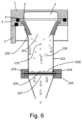
- Fig. 6 shows the collector device of Fig. 5 in use.
- particles 209 which have a variety of particle sizes within the respirable range and which may in some cases be agglomerated particles 210 are delivered through orifice 201 in substantially laminar flow and the current is drawn vertically downwards onto filter 206.
- the air current 211 is drawn through the filter whilst the entrained particles are retained on the filter 206. Because the underside of the filter 206 has only a narrow area of contact with the support, the support 207 has little or no effect on the pattern of deposition on the filter.
- Fig. 7A shows images of material collected on a filter in an apparatus according to the invention from a dry powder inhaler (fluticasone propionate 250 ⁇ g Accuhaler DPI) after 1, 2, 5 and 10 actuations at a magnification of x1000.
- a dry powder inhaler fluticasone propionate 250 ⁇ g Accuhaler DPI
- Fig. 7B shows images of material collected on a filter in an apparatus according to the invention from a pressurised metered dose inhaler (fluticasone propionate 125 ⁇ g Evohaler MDI) containing a suspension after 1, 2, 5 and 10 actuations at a magnification of x1000.
- a pressurised metered dose inhaler fluticasone propionate 125 ⁇ g Evohaler MDI
- Figs. 7A and 7B Collection of the samples of Figs. 7A and 7B was accomplished in an apparatus according to Fig. 4 in which a glass microfibre filter (Pall Corporation, A/E filter) having a nominal filter pore size of 1 ⁇ m was used.
- the reference scale on each image of Figs. 7A and 7B corresponds to 10 ⁇ m.
- Figs. 7A and 7B are dissolution graphs showing the rate of dissolution in a dissolution test for filters after 1, 2, 5 and 10 actuations.
- the dissolution graph in Fig. 8A corresponds to the filter collection results shown in Fig.7A whilst the dissolution graph in Fig. 8B corresponds to the filter collection results shown in Fig.7B .
- the dissolution time is shown in Figs. 8A and 8B to be effectively independent of the number of actuations, thus offering the possibility of greatly improved correlation with in vivo lung deposition.
- Suitable filters for use in the apparatus of the invention are generally those having a nominal pore size in the range of 1 to 3 ⁇ m. Since, in the apparatus of the invention, the filter is provided in-line in the flow pathway, suitable filters are preferably selected to have a pore size that is sufficiently small that the filter traps essentially all, and preferable not less than 90%, especially not less than 95% by weight of solids entrained in the air flow, whilst the resistance to air flow presented by the filter is relatively small. The following method may be used to evaluate filter suitability.
- a HPC5 vacuum pump (Copley Scientific) was used in conjunction with a TPK controller (Copley Scientific).
- a DFM 2000 digital flow meter was connected to a USP throat of an apparatus according to Fig. 4 without the filter present and the flow rate adjusted to 60L/min.
- a range of different filters were then inserted in series and tested. The drop in flow rate was measured with respect to flow rate with no filter present.
- the insertion of a filter creates a drop in flow rate associated with an increase in the resistance to the air flow within the apparatus, and a decrease in pore size is associated with a significant drop in flow rate.
- a significant drop in flow rate will undesirably modify the air flow behaviour within the apparatus due to the restrictive properties of the filter and will also lead to problems with trying to attain higher flow rates.
- the data in Table 1 demonstrates that the filters with pore size in the range of 1-3 ⁇ m tested have a limited influence on the restrictive flow through the apparatus, whereas at pore sizes of less than 1 ⁇ m more the effect on flow appears to become more significant. Studies have shown that filters with a pore size of 3 ⁇ m is sufficiently fine for capturing aerosols.
- a pore size of at least 1 ⁇ m is preferred, in practice it is the air-permeability of the filter that influences its suitability in the apparatus of the invention, and filters with pore size of less than 1 ⁇ m may be used where they do not substantially increase the resistance to flow, for example, result in a flow rate reduction of not more than 15%, preferably not more than 10% relative to absence of a filter.
- a collection apparatus comprising a modified Next Generation Impactor (NGI) incorporating a collection device as shown in Fig. 1 was used to collect respirable material as described below.
- NTI Next Generation Impactor
- the air velocity in the collection device was significantly reduced as compared with the air exit velocity in the conventional jets from an impactor nozzle, whilst laminar flow behaviour (Reynolds number: 500 ⁇ Re ⁇ 3000) is maintained across the calibrated flow rates of the NGI (30-100L/min).
- the difference in the air velocity exiting orifice 201 was calculated to be an order of magnitude less as a result of the use of a single, circular orifice (from 891cm/s to 83.7cm/s at 60L/min).
- the combination of low air flow velocity and the distribution of the whole pneumatic air across a large diameter orifice is adapted to enable uniform deposition of the aerosol dose.
- the dose collection device housed a removable holder for an appropriate 47mm diameter filter that was arranged orthogonally to the direction of the pneumatic flow.
- the dose collector was connected directly to a vacuum pump via a TPK controller (Critical Flow Controller Model TPK Copley Scientific, Nottingham UK).
- TPK controller Critical Flow Controller Model TPK Copley Scientific, Nottingham UK. The arrangement enabled the collection of all the dose corresponding to any remaining NGI stages of a conventional impactor and allowed a direct unimpeded pathway extending from the orifice to the filter.
- the impactor stage mass (which effectively corresponds to the particulate material collected from stage 2 to the finest particle collection stage of a standard NGI) of fluticasone propionate as collected in this device was compared with a standard in vitro NGI test with increasing number of actuations (1, 2, 5 and 10 shots) of a commercial fluticasone propionate DPI (250 ⁇ g Flixotide Accuhaler).
- the impactor stage mass was collected, corresponding to the cumulative mass collected below stage 2 of the NGI, stage 1 serving to remove larger particles leaving the respirable fraction to be collected as the ISM in subsequent stages.
- the ISM as collected on the stages of the standard impactor is dissolved in PBS solution and chemically analysed by HPLC to determine the mass.
- Fig. 9 there is excellent correlation over a range of mass loadings between the dose collected in the apparatus of the invention and the impactor stage mass collected in the standard NGI.
- the cumulative increase in collected mass is directly related to 1, 2, 5 and 10 shots of the same inhaler device.
- the apparatus of the invention provides an effective and simple means for determining aerosol dose, and independently of the number of delivered doses.
- the local deposition density of the fluticasone propionate particles increased with increasing drug loading with minimal aggregation and minimal in-situ agglomeration formation.
- Fig. 7A shows even deposition of fluticasone propionate from a DPI (250 ⁇ g Flixotide Accuhaler), whilst Fig. 7B shows the even deposition of fluticasone propionate from a metered dose inhaler (125 ⁇ g Flixotide Evohaler).
Landscapes
- Life Sciences & Earth Sciences (AREA)
- Health & Medical Sciences (AREA)
- Chemical & Material Sciences (AREA)
- Pathology (AREA)
- Physics & Mathematics (AREA)
- Analytical Chemistry (AREA)
- Biochemistry (AREA)
- General Health & Medical Sciences (AREA)
- General Physics & Mathematics (AREA)
- Immunology (AREA)
- Molecular Biology (AREA)
- Biomedical Technology (AREA)
- Engineering & Computer Science (AREA)
- Dispersion Chemistry (AREA)
- Medicinal Preparation (AREA)
- Acyclic And Carbocyclic Compounds In Medicinal Compositions (AREA)
Claims (18)
- Verfahren zum Sammeln eines aerosolisierten lungengängigen Anteils einer inhalierbaren medizinischen Formulierung, die lungengängige und nicht lungengängige Partikelgrößenanteile enthält, aufweisend:Erzeugen einer aerosolisierten Dosis der medizinischen Formulierung, die lungengängige und nicht lungengängige Partikel enthält;Entfernen von Partikeln nicht lungengängiger Größe aus der aerosolisierten Dosis durch Trägheitsabscheidung;Zuführen eines pneumatischen Stroms, der lungengängige Partikel mitführt, entlang eines uneingeschränkten Wegs zu einer Filtereinheit (203), die einen Filter (206) und einen Filterträger (207) aufweist, wobei der uneingeschränkte Weg eine dem Filter (206) gegenüberliegende Öffnung (201) aufweist, durch die der pneumatische Strom zu dem Filter (206) geleitet wird;Durchführen einer Filtration des pneumatischen Stroms an dem Filter (206), so dass die Partikel an dem Filter (206) zurückgehalten werden;- wobei der Filter (206) eine vordere Oberfläche, auf die der pneumatische Strom geleitet wird, und eine rückwärtige Oberfläche aufweist und der Filterträger (207) ein oder mehrere längliche Stützelemente (208) aufweist, die sich auf der der Öffnung (201) gegenüberliegenden Oberfläche des Filters (206) über den Weg erstrecken, um einen zentralen Bereich des Filters (206) zu stützen, wobei der Filterträger (207) zwei bis sechs Öffnungen definiert und nicht mehr als 80 % der Oberfläche der gegenüberliegenden Oberfläche blockiert,wobei der pneumatische Strom durch eine Saugquelle erzeugt wird, die über die rückwärtige Oberfläche des Filters (206) Sog ausübt;und wobei der pneumatische Strom durch die Öffnung (201) als Laminarstrom in Richtung auf den Filter (206) geleitet wird.
- Verfahren nach Anspruch 1,
wobei der durch die Öffnung (201) zugeführte pneumatische Strom eine Reynolds-Zahl zwischen 500 und 3000 aufweist. - Verfahren nach Anspruch 2,
wobei die Öffnung (201) eine runde Öffnung mit einem Durchmesser von 2 bis 5 cm ist. - Verfahren nach Anspruch 1,
wobei die Öffnung (201) einen Durchmesser von nicht weniger als 14 mm aufweist, wobei optional der Abstand zwischen der Öffnung (201) und dem Filter (206) vorteilhafterweise nicht größer ist als das Dreifache des Durchmessers der Öffnung (201). - Verfahren zum Bestimmen der Auflösungseigenschaften einer inhalierbaren medizinischen Formulierung, aufweisend:Sammeln eines aerosolisierten lungengängigen Anteils einer inhalierbaren medizinischen Formulierung, die lungengängige und nicht lungengängige Partikelgrößenanteile enthält, nach einem der Ansprüche 1 bis 4,und Unterziehen des Filters (206), der die gesammelten Partikel trägt, einem Auflösungstest.
- Verfahren nach einem der Ansprüche 1 bis 5,
wobei die Saugquelle derart angeordnet ist, dass sie eine pneumatische Strömungsrate von 10 bis 100 Litern pro Minute erzeugt. - Verfahren nach einem der Ansprüche 1 bis 6,
wobei der pneumatische Strom mit einer Strömungsgeschwindigkeit von nicht mehr als 250 cm/s auf den Filter (206) geleitet wird. - Verfahren nach einem der Ansprüche 1 bis 7,
wobei zwei oder mehr aerosolisierte Dosen des medizinischen Pulvers nacheinander erzeugt werden und ein lungengängiger Anteil jeder Dosis kumulativ auf dem Filter (206) gesammelt wird. - Verfahren nach einem der Ansprüche 1 bis 8,
wobei die an dem Filter (206) gesammelten Dosen im Wesentlichen dem gesamten lungengängigen Anteil der in der jeweiligen Dosis erzeugten Partikel entsprechen. - Verfahren nach einem der Ansprüche 1 bis 8,
wobei der oder jeder an dem Filter (206) gesammelte lungengängige Anteil ein proportionaler Anteil des in der jeweiligen Dosis erzeugten lungengängigen Anteils ist, wobei das Verfahren ferner einen oder mehrere Schritte zur Trägheitsabscheidung von einem oder mehreren lungengängigen Partikelanteilen umfasst, bevor die Filtration des pneumatischen Stroms an dem Filter (206) ausgeführt wird. - Vorrichtung zum Ausführen des Verfahrens nach einem der Ansprüche 1 bis 10, aufweisend:- einen Einlass zum Empfangen einer aerosolisierten Dosis der medizinischen Formulierung;- eine Saugquelle zum Erzeugen eines pneumatischen Stroms durch die Vorrichtung;- einen Kanal, der einen Weg definiert, der sich von dem Einlass zu der Saugquelle erstreckt;- einen Dosis-Sammelabschnitt, der sich in dem Weg befindet und eine Einlassöffnung (201) und eine Filtereinheit (203) aufweist, wobei die Filtereinheit (203) einen luftdurchlässigen Filter (206) und einen Filterträger (207) aufweist, wobei der Filter (206) gegenüber der Öffnung (201) positioniert ist und sich über den Weg erstreckt, um den pneumatischen Strom zu filtern, so dass darin enthaltenes Partikelmaterial an dem Filter (206) zurückgehalten wird,
dadurch gekennzeichnet, dass die Öffnung (201) derart bemessen und konfiguriert ist, dass sie eine uneingeschränkte Fläche aufweist, die nicht weniger als 75 % der Fläche des Filters (206) beträgt, auf der die Dosis gesammelt wird;- wobei die Saugquelle mit dem Weg stromabwärts von der Filtereinheit (203) in Verbindung steht; und- wobei der Filterträger (207) ein oder mehrere Stützelemente (208) aufweist, die sich über den Weg auf der der Öffnung (201) gegenüberliegenden Oberfläche des Filters (206) erstrecken, um einen zentralen Bereich des Filters (206) zu stützen, wobei der Filterträger (207) zwei bis sechs Öffnungen definiert und nicht mehr als 80 % der Fläche der gegenüberliegenden Oberfläche blockiert. - Vorrichtung nach Anspruch 11,
die ferner eine Entfernungsvorrichtung umfasst, die sich in dem Weg stromaufwärts von dem Dosis-Sammelabschnitt befindet, um Partikel nicht lungengängiger Partikelgröße aus dem Weg zu entfernen. - Vorrichtung nach Anspruch 12,
wobei die Entfernungsvorrichtung dazu ausgebildet ist, einen nicht lungengängigen Partikelanteil zu entfernen, und der Dosis-Sammelabschnitt dazu ausgebildet ist, den lungengängigen Anteil der medizinischen Formulierung zu sammeln. - Vorrichtung nach Anspruch 12,
wobei in dem Weg zwischen der Entfernungsvorrichtung und dem Dosis-Sammelabschnitt eine oder mehrere Trägheitsabscheideeinheiten zum Eliminieren eines oder mehrerer weiterer Partikelgrößenanteile aus dem pneumatischen Strom vorgesehen sind, bevor dieser den Dosis-Sammelabschnitt erreicht. - Vorrichtung nach einem der Ansprüche 11 bis 14,
wobei der Filter (206) eine Porengröße von mindestens 1 µm aufweist. - Vorrichtung nach einem der Ansprüche 11 bis 15,
wobei die Öffnung (201) im Wesentlichen rechtwinklig zu einer Oberfläche des Filters (206) angeordnet ist, auf die die Partikel auftreffen. - Vorrichtung nach einem der Ansprüche 11 bis 16,
wobei die Vorrichtung eine Entfernungsvorrichtung zum Entfernen von Partikeln nicht lungengängiger Partikelgröße aufweist und die Anordnung derart ist, dass alle nach dem Entfernen von nicht lungengängigen Partikeln in dem pneumatischen Luftstrom verbliebenen Partikel dem Dosis-Sammelabschnitt zugeführt werden. - Vorrichtung nach einem der Ansprüche 11 bis 17,
die ferner stromaufwärts von der Öffnung (201) eine Trägheitsabscheidevorrichtung mit einer Zuführdüse aufweist, deren Querschnittsfläche kleiner ist als die Querschnittsfläche der Öffnung (201).
Applications Claiming Priority (2)
| Application Number | Priority Date | Filing Date | Title |
|---|---|---|---|
| GBGB1516802.4A GB201516802D0 (en) | 2015-09-22 | 2015-09-22 | Apparatus and method for determination of the dose of a powder inhalation formulation |
| PCT/GB2016/052957 WO2017051180A1 (en) | 2015-09-22 | 2016-09-22 | Apparatus and method for determination of the fine particle dose of a powder inhalation formulation |
Publications (3)
| Publication Number | Publication Date |
|---|---|
| EP3353522A1 EP3353522A1 (de) | 2018-08-01 |
| EP3353522C0 EP3353522C0 (de) | 2025-06-25 |
| EP3353522B1 true EP3353522B1 (de) | 2025-06-25 |
Family
ID=54544647
Family Applications (1)
| Application Number | Title | Priority Date | Filing Date |
|---|---|---|---|
| EP16777742.4A Active EP3353522B1 (de) | 2015-09-22 | 2016-09-22 | Vorrichtung und verfahren zur bestimmung der feinpartikeldosis einer pulverinhalationsformulierung |
Country Status (8)
| Country | Link |
|---|---|
| US (2) | US10724928B2 (de) |
| EP (1) | EP3353522B1 (de) |
| CN (1) | CN108027303B (de) |
| AU (1) | AU2016328797B2 (de) |
| CA (1) | CA2998988C (de) |
| ES (1) | ES3038202T3 (de) |
| GB (3) | GB201516802D0 (de) |
| WO (1) | WO2017051180A1 (de) |
Families Citing this family (17)
| Publication number | Priority date | Publication date | Assignee | Title |
|---|---|---|---|---|
| GB201516802D0 (en) | 2015-09-22 | 2015-11-04 | Nanopharm Ltd | Apparatus and method for determination of the dose of a powder inhalation formulation |
| US11380438B2 (en) | 2017-09-27 | 2022-07-05 | Honeywell International Inc. | Respiration-vocalization data collection system for air quality determination |
| EP3721203B1 (de) | 2017-12-07 | 2025-06-25 | The Governors of the University of Alberta | Filter zur nachahmung von regionaler lungenablagerung |
| US10876949B2 (en) | 2019-04-26 | 2020-12-29 | Honeywell International Inc. | Flow device and associated method and system |
| CN110559738B (zh) * | 2019-08-29 | 2021-07-02 | 华中科技大学 | 一种过滤器内部颗粒沉积过程可视化装置及方法 |
| US12416551B2 (en) * | 2019-11-15 | 2025-09-16 | Nanopharm Limited | Apparatus for collection of particles of an inhalable formulation |
| AU2019474706B2 (en) * | 2019-11-15 | 2025-10-02 | Nanopharm Limited | In vitro release testing (IVRT) device for orally inhaled drug products |
| US11221288B2 (en) * | 2020-01-21 | 2022-01-11 | Honeywell International Inc. | Fluid composition sensor device and method of using the same |
| US11391613B2 (en) | 2020-02-14 | 2022-07-19 | Honeywell International Inc. | Fluid composition sensor device and method of using the same |
| US11333593B2 (en) | 2020-02-14 | 2022-05-17 | Honeywell International Inc. | Fluid composition sensor device and method of using the same |
| US11181456B2 (en) | 2020-02-14 | 2021-11-23 | Honeywell International Inc. | Fluid composition sensor device and method of using the same |
| US12111257B2 (en) | 2020-08-26 | 2024-10-08 | Honeywell International Inc. | Fluid composition sensor device and method of using the same |
| CN116583316A (zh) * | 2020-10-15 | 2023-08-11 | 普罗沃锐斯科学有限公司 | 用于吸入器测试的系统和方法 |
| US11835432B2 (en) | 2020-10-26 | 2023-12-05 | Honeywell International Inc. | Fluid composition sensor device and method of using the same |
| US12281976B2 (en) | 2021-05-13 | 2025-04-22 | Honeywell International Inc. | In situ fluid sampling device and method of using the same |
| JP2023183682A (ja) * | 2022-06-16 | 2023-12-28 | 新東工業株式会社 | ガス流路、ガス検出システム |
| WO2026006876A1 (en) * | 2024-07-02 | 2026-01-08 | The University Of Sydney | Apparatus and method to collect respirable drug particles |
Family Cites Families (25)
| Publication number | Priority date | Publication date | Assignee | Title |
|---|---|---|---|---|
| US3748905A (en) * | 1971-12-30 | 1973-07-31 | J Fletcher | Vacuum probe surface sampler |
| SU503159A1 (ru) * | 1974-06-21 | 1976-02-15 | Всесоюзный Дважды Ордена Трудового Красного Знамени Теплотехнический Научно-Исследовательский Институт Им.Ф.Э.Дзержинского | Устройство дл отбора проб запыленного газа |
| US4092221A (en) * | 1975-04-10 | 1978-05-30 | Schlichting Jr Harold E | Apparatus for biologically monitoring air quality |
| US4046512A (en) * | 1976-02-20 | 1977-09-06 | Westinghouse Electric Corporation | Device for indicating overheating in generators |
| US4204550A (en) * | 1979-03-07 | 1980-05-27 | Philip Morris Incorporated | Apparatus for fractionation of a standard puff of smoke from a smoking machine |
| DE3107758A1 (de) * | 1980-03-04 | 1982-01-28 | National Research Development Corp., London | Auswaschvorrichtung |
| US4461183A (en) | 1982-03-05 | 1984-07-24 | Wedding James B | Ambient aerosol sampler inlet |
| EP0227679A1 (de) * | 1984-09-26 | 1987-07-08 | ANDERSSON, Jan Peter | Verfahren und vorrichtung zum auffangen und analysieren von teilchen |
| US4902318A (en) * | 1988-05-25 | 1990-02-20 | The United States Of America As Represented By The Administrator Of The Environmental Protection Agency | Inlet apparatus for gas-aerosol sampling |
| US4972957A (en) * | 1988-09-27 | 1990-11-27 | Regents Of The University Of Minnesota | Particle concentrating sampler |
| US5317930A (en) * | 1991-09-18 | 1994-06-07 | Wedding & Associates, Inc. | Constant flowrate controller for an aerosol sampler using a filter |
| US5702506A (en) * | 1996-10-16 | 1997-12-30 | Institute Of Occupational Safety And Health, Council Of Labor Affairs, Executive Yuan | Method and device for aerosol size-selective sampling |
| GC0000091A (en) | 1998-12-31 | 2004-06-30 | Shell Int Research | Method for removing condensables from a natural gas stream. |
| US6379412B1 (en) * | 2000-07-21 | 2002-04-30 | Albert Porterfield | Air filtering assembly |
| US6632271B2 (en) * | 2000-08-21 | 2003-10-14 | Larry Don Robertson | MBI bioaerosol vortex cassette |
| US20040002166A1 (en) | 2002-06-27 | 2004-01-01 | Wiederin Daniel R. | Remote analysis using aerosol sample transport |
| US6905594B2 (en) | 2002-10-11 | 2005-06-14 | G6 Science Corp. | Filter apparatus and methods to capture a desired amount of material from a sample suspension for monolayer deposition, analysis or other uses |
| US20080196514A1 (en) * | 2007-02-16 | 2008-08-21 | Kenny James A | Inhalable Sampler |
| US7934434B2 (en) * | 2007-11-30 | 2011-05-03 | Pharmaceutical Product Development, Inc. | Apparatus and method for analysis of dry powder inhaler products |
| JP4714915B1 (ja) | 2010-06-30 | 2011-07-06 | ニッタ株式会社 | 慣性フィルタおよび粒子分級装置 |
| WO2013063426A2 (en) * | 2011-10-26 | 2013-05-02 | Research Triangle Institute, International | Aerosol exposure monitoring |
| CN202420926U (zh) | 2011-12-23 | 2012-09-05 | 佛山市环保技术与装备研发专业中心 | 一种pm1联体多级切割采样头 |
| CN103257060B (zh) * | 2013-05-13 | 2015-06-10 | 广西大学 | 高效雾化捕集采样器 |
| CN103674624B (zh) * | 2013-12-09 | 2016-08-17 | 东南大学 | 富集环境空气中重金属的采样膜、采样器及其应用方法 |
| GB201516802D0 (en) | 2015-09-22 | 2015-11-04 | Nanopharm Ltd | Apparatus and method for determination of the dose of a powder inhalation formulation |
-
2015
- 2015-09-22 GB GBGB1516802.4A patent/GB201516802D0/en not_active Ceased
-
2016
- 2016-09-22 US US15/761,143 patent/US10724928B2/en active Active
- 2016-09-22 CA CA2998988A patent/CA2998988C/en active Active
- 2016-09-22 WO PCT/GB2016/052957 patent/WO2017051180A1/en not_active Ceased
- 2016-09-22 AU AU2016328797A patent/AU2016328797B2/en active Active
- 2016-09-22 GB GB1616163.0A patent/GB2547961B/en active Active
- 2016-09-22 ES ES16777742T patent/ES3038202T3/es active Active
- 2016-09-22 CN CN201680055143.XA patent/CN108027303B/zh active Active
- 2016-09-22 GB GB2019158.1A patent/GB2587287B/en active Active
- 2016-09-22 EP EP16777742.4A patent/EP3353522B1/de active Active
-
2020
- 2020-06-17 US US16/903,405 patent/US11181447B2/en active Active
Also Published As
| Publication number | Publication date |
|---|---|
| GB2547961B (en) | 2021-10-20 |
| AU2016328797A1 (en) | 2018-05-10 |
| CA2998988C (en) | 2022-08-09 |
| GB2587287B (en) | 2021-10-20 |
| CN108027303B (zh) | 2021-09-21 |
| US10724928B2 (en) | 2020-07-28 |
| GB201616163D0 (en) | 2016-11-09 |
| GB202019158D0 (en) | 2021-01-20 |
| AU2016328797A2 (en) | 2020-09-03 |
| CA2998988A1 (en) | 2017-03-30 |
| ES3038202T3 (en) | 2025-10-10 |
| WO2017051180A1 (en) | 2017-03-30 |
| GB201516802D0 (en) | 2015-11-04 |
| EP3353522C0 (de) | 2025-06-25 |
| GB2547961A (en) | 2017-09-06 |
| EP3353522A1 (de) | 2018-08-01 |
| US20200319062A1 (en) | 2020-10-08 |
| GB2587287A (en) | 2021-03-24 |
| CN108027303A (zh) | 2018-05-11 |
| US11181447B2 (en) | 2021-11-23 |
| AU2016328797B2 (en) | 2021-07-15 |
| US20180275022A1 (en) | 2018-09-27 |
Similar Documents
| Publication | Publication Date | Title |
|---|---|---|
| US11181447B2 (en) | Apparatus and method for determination of the fine particle dose of a powder inhalation formulation | |
| JP6450388B2 (ja) | ドライパウダー吸入器 | |
| EP2186536A1 (de) | Abstandstück oder Aktuator für die frühzeitige Entfernung des nicht-einatembaren Anteils eines medizinischen Aerosols | |
| De Boer et al. | Design and application of a new modular adapter for laser diffraction characterization of inhalation aerosols | |
| Dolovich | Measurement of particle size characteristics of metered dose inhaler (MDI) aerosols | |
| EP3403065B1 (de) | Kaskadenimpaktorplattenbeschichtung | |
| US12416551B2 (en) | Apparatus for collection of particles of an inhalable formulation | |
| Biddiscombe et al. | A system for the production and delivery of monodisperse salbutamol aerosols to the lungs | |
| KR101857834B1 (ko) | 계량된-투여량 흡입기 액츄에이터, 계량된-투여량 흡입기 | |
| Wang et al. | A dry powder inhaler with reduced mouth–throat deposition | |
| EP1613381A1 (de) | Vorrichtung zur pulmonaren arzneimittelverabreichung | |
| US7659725B2 (en) | Method for assessing the suitability of metered dose inhaler actuators | |
| Omer et al. | Comparison between the next generation impactor and the twin glass impinge as model pulmonary drug delivery devices | |
| Copley | Assessing dry powder inhalers | |
| El-Araud et al. | The effect of dose on the characterization of aerodynamic particle-size distributions of beclomethasone dipropionate metered-dose inhalers | |
| DOLOVICH | Inhaler (MDI) Aerosols |
Legal Events
| Date | Code | Title | Description |
|---|---|---|---|
| STAA | Information on the status of an ep patent application or granted ep patent |
Free format text: STATUS: THE INTERNATIONAL PUBLICATION HAS BEEN MADE |
|
| PUAI | Public reference made under article 153(3) epc to a published international application that has entered the european phase |
Free format text: ORIGINAL CODE: 0009012 |
|
| STAA | Information on the status of an ep patent application or granted ep patent |
Free format text: STATUS: REQUEST FOR EXAMINATION WAS MADE |
|
| 17P | Request for examination filed |
Effective date: 20180420 |
|
| AK | Designated contracting states |
Kind code of ref document: A1 Designated state(s): AL AT BE BG CH CY CZ DE DK EE ES FI FR GB GR HR HU IE IS IT LI LT LU LV MC MK MT NL NO PL PT RO RS SE SI SK SM TR |
|
| AX | Request for extension of the european patent |
Extension state: BA ME |
|
| DAV | Request for validation of the european patent (deleted) | ||
| DAX | Request for extension of the european patent (deleted) | ||
| STAA | Information on the status of an ep patent application or granted ep patent |
Free format text: STATUS: EXAMINATION IS IN PROGRESS |
|
| 17Q | First examination report despatched |
Effective date: 20210705 |
|
| GRAP | Despatch of communication of intention to grant a patent |
Free format text: ORIGINAL CODE: EPIDOSNIGR1 |
|
| STAA | Information on the status of an ep patent application or granted ep patent |
Free format text: STATUS: GRANT OF PATENT IS INTENDED |
|
| INTG | Intention to grant announced |
Effective date: 20241004 |
|
| GRAJ | Information related to disapproval of communication of intention to grant by the applicant or resumption of examination proceedings by the epo deleted |
Free format text: ORIGINAL CODE: EPIDOSDIGR1 |
|
| STAA | Information on the status of an ep patent application or granted ep patent |
Free format text: STATUS: EXAMINATION IS IN PROGRESS |
|
| GRAP | Despatch of communication of intention to grant a patent |
Free format text: ORIGINAL CODE: EPIDOSNIGR1 |
|
| STAA | Information on the status of an ep patent application or granted ep patent |
Free format text: STATUS: GRANT OF PATENT IS INTENDED |
|
| INTC | Intention to grant announced (deleted) | ||
| INTG | Intention to grant announced |
Effective date: 20250116 |
|
| GRAS | Grant fee paid |
Free format text: ORIGINAL CODE: EPIDOSNIGR3 |
|
| GRAA | (expected) grant |
Free format text: ORIGINAL CODE: 0009210 |
|
| STAA | Information on the status of an ep patent application or granted ep patent |
Free format text: STATUS: THE PATENT HAS BEEN GRANTED |
|
| RAP3 | Party data changed (applicant data changed or rights of an application transferred) |
Owner name: NANOPHARM LIMITED |
|
| AK | Designated contracting states |
Kind code of ref document: B1 Designated state(s): AL AT BE BG CH CY CZ DE DK EE ES FI FR GB GR HR HU IE IS IT LI LT LU LV MC MK MT NL NO PL PT RO RS SE SI SK SM TR |
|
| REG | Reference to a national code |
Ref country code: GB Ref legal event code: FG4D |
|
| REG | Reference to a national code |
Ref country code: CH Ref legal event code: EP |
|
| REG | Reference to a national code |
Ref country code: CH Ref legal event code: EP |
|
| REG | Reference to a national code |
Ref country code: IE Ref legal event code: FG4D |
|
| REG | Reference to a national code |
Ref country code: DE Ref legal event code: R096 Ref document number: 602016092667 Country of ref document: DE |
|
| U01 | Request for unitary effect filed |
Effective date: 20250718 |
|
| U07 | Unitary effect registered |
Designated state(s): AT BE BG DE DK EE FI FR IT LT LU LV MT NL PT RO SE SI Effective date: 20250725 |
|
| U20 | Renewal fee for the european patent with unitary effect paid |
Year of fee payment: 10 Effective date: 20250807 |
|
| REG | Reference to a national code |
Ref country code: CH Ref legal event code: U11 Free format text: ST27 STATUS EVENT CODE: U-0-0-U10-U11 (AS PROVIDED BY THE NATIONAL OFFICE) Effective date: 20251001 |
|
| REG | Reference to a national code |
Ref country code: ES Ref legal event code: FG2A Ref document number: 3038202 Country of ref document: ES Kind code of ref document: T3 Effective date: 20251010 |
|
| PG25 | Lapsed in a contracting state [announced via postgrant information from national office to epo] |
Ref country code: NO Free format text: LAPSE BECAUSE OF FAILURE TO SUBMIT A TRANSLATION OF THE DESCRIPTION OR TO PAY THE FEE WITHIN THE PRESCRIBED TIME-LIMIT Effective date: 20250925 |
|
| PGFP | Annual fee paid to national office [announced via postgrant information from national office to epo] |
Ref country code: GR Payment date: 20250904 Year of fee payment: 10 |
|
| PGFP | Annual fee paid to national office [announced via postgrant information from national office to epo] |
Ref country code: GB Payment date: 20250703 Year of fee payment: 10 |
|
| PG25 | Lapsed in a contracting state [announced via postgrant information from national office to epo] |
Ref country code: HR Free format text: LAPSE BECAUSE OF FAILURE TO SUBMIT A TRANSLATION OF THE DESCRIPTION OR TO PAY THE FEE WITHIN THE PRESCRIBED TIME-LIMIT Effective date: 20250625 |
|
| PG25 | Lapsed in a contracting state [announced via postgrant information from national office to epo] |
Ref country code: RS Free format text: LAPSE BECAUSE OF FAILURE TO SUBMIT A TRANSLATION OF THE DESCRIPTION OR TO PAY THE FEE WITHIN THE PRESCRIBED TIME-LIMIT Effective date: 20250925 |
|
| PGFP | Annual fee paid to national office [announced via postgrant information from national office to epo] |
Ref country code: IE Payment date: 20250702 Year of fee payment: 10 |
|
| REG | Reference to a national code |
Ref country code: GR Ref legal event code: EP Ref document number: 20250401766 Country of ref document: GR Effective date: 20251009 |
|
| PG25 | Lapsed in a contracting state [announced via postgrant information from national office to epo] |
Ref country code: IS Free format text: LAPSE BECAUSE OF FAILURE TO SUBMIT A TRANSLATION OF THE DESCRIPTION OR TO PAY THE FEE WITHIN THE PRESCRIBED TIME-LIMIT Effective date: 20251025 |
|
| PG25 | Lapsed in a contracting state [announced via postgrant information from national office to epo] |
Ref country code: SM Free format text: LAPSE BECAUSE OF FAILURE TO SUBMIT A TRANSLATION OF THE DESCRIPTION OR TO PAY THE FEE WITHIN THE PRESCRIBED TIME-LIMIT Effective date: 20250625 |
|
| PGFP | Annual fee paid to national office [announced via postgrant information from national office to epo] |
Ref country code: CH Payment date: 20251001 Year of fee payment: 10 |
|
| PG25 | Lapsed in a contracting state [announced via postgrant information from national office to epo] |
Ref country code: CZ Free format text: LAPSE BECAUSE OF FAILURE TO SUBMIT A TRANSLATION OF THE DESCRIPTION OR TO PAY THE FEE WITHIN THE PRESCRIBED TIME-LIMIT Effective date: 20250625 |
|
| PG25 | Lapsed in a contracting state [announced via postgrant information from national office to epo] |
Ref country code: PL Free format text: LAPSE BECAUSE OF FAILURE TO SUBMIT A TRANSLATION OF THE DESCRIPTION OR TO PAY THE FEE WITHIN THE PRESCRIBED TIME-LIMIT Effective date: 20250625 |
|
| PG25 | Lapsed in a contracting state [announced via postgrant information from national office to epo] |
Ref country code: SK Free format text: LAPSE BECAUSE OF FAILURE TO SUBMIT A TRANSLATION OF THE DESCRIPTION OR TO PAY THE FEE WITHIN THE PRESCRIBED TIME-LIMIT Effective date: 20250625 |
|
| PGFP | Annual fee paid to national office [announced via postgrant information from national office to epo] |
Ref country code: ES Payment date: 20251017 Year of fee payment: 10 |