EP3353460B1 - Screw plug - Google Patents
Screw plug Download PDFInfo
- Publication number
- EP3353460B1 EP3353460B1 EP16757593.5A EP16757593A EP3353460B1 EP 3353460 B1 EP3353460 B1 EP 3353460B1 EP 16757593 A EP16757593 A EP 16757593A EP 3353460 B1 EP3353460 B1 EP 3353460B1
- Authority
- EP
- European Patent Office
- Prior art keywords
- screw
- flange
- base
- engagement means
- opening
- Prior art date
- Legal status (The legal status is an assumption and is not a legal conclusion. Google has not performed a legal analysis and makes no representation as to the accuracy of the status listed.)
- Active
Links
- 230000002093 peripheral effect Effects 0.000 claims description 17
- 238000003780 insertion Methods 0.000 claims description 14
- 230000037431 insertion Effects 0.000 claims description 14
- 239000004954 Polyphthalamide Substances 0.000 claims description 8
- 229920006375 polyphtalamide Polymers 0.000 claims description 8
- 230000015572 biosynthetic process Effects 0.000 claims description 5
- 239000012530 fluid Substances 0.000 claims description 5
- 239000004033 plastic Substances 0.000 claims description 5
- 230000004323 axial length Effects 0.000 claims description 3
- 230000007704 transition Effects 0.000 claims description 3
- 239000011521 glass Substances 0.000 claims 1
- 238000001746 injection moulding Methods 0.000 claims 1
- 239000000463 material Substances 0.000 description 7
- 231100000817 safety factor Toxicity 0.000 description 4
- 239000003365 glass fiber Substances 0.000 description 3
- 230000003014 reinforcing effect Effects 0.000 description 3
- 241001017167 Lycium minimum Species 0.000 description 1
- 230000005540 biological transmission Effects 0.000 description 1
- 238000009833 condensation Methods 0.000 description 1
- 230000005494 condensation Effects 0.000 description 1
- 239000004035 construction material Substances 0.000 description 1
- 230000000694 effects Effects 0.000 description 1
- 238000005516 engineering process Methods 0.000 description 1
- 238000011089 mechanical engineering Methods 0.000 description 1
- 239000002184 metal Substances 0.000 description 1
- 229920002647 polyamide Polymers 0.000 description 1
- 239000002861 polymer material Substances 0.000 description 1
- 230000002787 reinforcement Effects 0.000 description 1
- 229920006024 semi-aromatic copolyamide Polymers 0.000 description 1
- 230000006641 stabilisation Effects 0.000 description 1
- 238000011105 stabilization Methods 0.000 description 1
- 239000000126 substance Substances 0.000 description 1
- 229920001169 thermoplastic Polymers 0.000 description 1
- 239000004416 thermosoftening plastic Substances 0.000 description 1
Images


Classifications
-
- F—MECHANICAL ENGINEERING; LIGHTING; HEATING; WEAPONS; BLASTING
- F16—ENGINEERING ELEMENTS AND UNITS; GENERAL MEASURES FOR PRODUCING AND MAINTAINING EFFECTIVE FUNCTIONING OF MACHINES OR INSTALLATIONS; THERMAL INSULATION IN GENERAL
- F16B—DEVICES FOR FASTENING OR SECURING CONSTRUCTIONAL ELEMENTS OR MACHINE PARTS TOGETHER, e.g. NAILS, BOLTS, CIRCLIPS, CLAMPS, CLIPS OR WEDGES; JOINTS OR JOINTING
- F16B31/00—Screwed connections specially modified in view of tensile load; Break-bolts
- F16B31/02—Screwed connections specially modified in view of tensile load; Break-bolts for indicating the attainment of a particular tensile load or limiting tensile load
- F16B31/021—Screwed connections specially modified in view of tensile load; Break-bolts for indicating the attainment of a particular tensile load or limiting tensile load by means of a frangible part
-
- F—MECHANICAL ENGINEERING; LIGHTING; HEATING; WEAPONS; BLASTING
- F16—ENGINEERING ELEMENTS AND UNITS; GENERAL MEASURES FOR PRODUCING AND MAINTAINING EFFECTIVE FUNCTIONING OF MACHINES OR INSTALLATIONS; THERMAL INSULATION IN GENERAL
- F16B—DEVICES FOR FASTENING OR SECURING CONSTRUCTIONAL ELEMENTS OR MACHINE PARTS TOGETHER, e.g. NAILS, BOLTS, CIRCLIPS, CLAMPS, CLIPS OR WEDGES; JOINTS OR JOINTING
- F16B23/00—Specially shaped nuts or heads of bolts or screws for rotations by a tool
- F16B23/0092—Specially shaped nuts or heads of bolts or screws for rotations by a tool with a head engageable by two or more different tools
-
- F—MECHANICAL ENGINEERING; LIGHTING; HEATING; WEAPONS; BLASTING
- F16—ENGINEERING ELEMENTS AND UNITS; GENERAL MEASURES FOR PRODUCING AND MAINTAINING EFFECTIVE FUNCTIONING OF MACHINES OR INSTALLATIONS; THERMAL INSULATION IN GENERAL
- F16B—DEVICES FOR FASTENING OR SECURING CONSTRUCTIONAL ELEMENTS OR MACHINE PARTS TOGETHER, e.g. NAILS, BOLTS, CIRCLIPS, CLAMPS, CLIPS OR WEDGES; JOINTS OR JOINTING
- F16B35/00—Screw-bolts; Stay-bolts; Screw-threaded studs; Screws; Set screws
- F16B35/04—Screw-bolts; Stay-bolts; Screw-threaded studs; Screws; Set screws with specially-shaped head or shaft in order to fix the bolt on or in an object
- F16B35/06—Specially-shaped heads
-
- F—MECHANICAL ENGINEERING; LIGHTING; HEATING; WEAPONS; BLASTING
- F16—ENGINEERING ELEMENTS AND UNITS; GENERAL MEASURES FOR PRODUCING AND MAINTAINING EFFECTIVE FUNCTIONING OF MACHINES OR INSTALLATIONS; THERMAL INSULATION IN GENERAL
- F16L—PIPES; JOINTS OR FITTINGS FOR PIPES; SUPPORTS FOR PIPES, CABLES OR PROTECTIVE TUBING; MEANS FOR THERMAL INSULATION IN GENERAL
- F16L55/00—Devices or appurtenances for use in, or in connection with, pipes or pipe systems
- F16L55/10—Means for stopping flow from or in pipes or hoses
- F16L55/11—Plugs
- F16L55/1108—Plugs fixed by screwing or by means of a screw-threaded ring
-
- F—MECHANICAL ENGINEERING; LIGHTING; HEATING; WEAPONS; BLASTING
- F16—ENGINEERING ELEMENTS AND UNITS; GENERAL MEASURES FOR PRODUCING AND MAINTAINING EFFECTIVE FUNCTIONING OF MACHINES OR INSTALLATIONS; THERMAL INSULATION IN GENERAL
- F16B—DEVICES FOR FASTENING OR SECURING CONSTRUCTIONAL ELEMENTS OR MACHINE PARTS TOGETHER, e.g. NAILS, BOLTS, CIRCLIPS, CLAMPS, CLIPS OR WEDGES; JOINTS OR JOINTING
- F16B33/00—Features common to bolt and nut
- F16B33/004—Sealing; Insulation
-
- F—MECHANICAL ENGINEERING; LIGHTING; HEATING; WEAPONS; BLASTING
- F16—ENGINEERING ELEMENTS AND UNITS; GENERAL MEASURES FOR PRODUCING AND MAINTAINING EFFECTIVE FUNCTIONING OF MACHINES OR INSTALLATIONS; THERMAL INSULATION IN GENERAL
- F16B—DEVICES FOR FASTENING OR SECURING CONSTRUCTIONAL ELEMENTS OR MACHINE PARTS TOGETHER, e.g. NAILS, BOLTS, CIRCLIPS, CLAMPS, CLIPS OR WEDGES; JOINTS OR JOINTING
- F16B35/00—Screw-bolts; Stay-bolts; Screw-threaded studs; Screws; Set screws
- F16B35/02—Screw-bolts; Stay-bolts; Screw-threaded studs; Screws; Set screws divided longitudinally
Definitions
- the present invention relates to a screw plug for an outlet opening of housings carrying fluids, comprising a circular cylindrical screw-in section with an external thread and a contact flange with an enlarged outer diameter at one end of the screw-in section compared to the screw-in section, the screw-in section and the contact flange being designed as a one-piece, material-uniform plastic injection-molded part , and the screw-in section is closed at one end with a base and a recess runs through the center of the contact flange and the screw-in section in the longitudinal direction as an internal engagement for a tool, which ends at the base and opposite the base has an insertion opening for the tool.
- a screw plug of the type described above for the hydraulic system is, for example, from DE 10 2013 101 972 A1 known. Such screw plugs are used in hydraulic components or hydraulic components, for example in mechanical engineering and in vehicle technology.
- a tightening torque of 17 Nm is generally used for metal fasteners. Such a tightening torque is also required for screw plugs made of plastic. For a breakaway torque, a safety factor of at least 2.5 compared to the tightening torque is required. However, these requirements cannot be applied to a screw plug that only has an internal engagement that is designed, for example, as a cross recess.
- the present invention is based on the object of improving a screw plug made of plastic of the type described above in such a way that the tightening torques of, for example, 17 Nm customary for metallic connecting elements are guaranteed and at the same time the safety factor in the event of a head tear can be reduced to 2, for example Compared to the usual safety factors of 2.5 to 3. This is based on the specifications of the standards DIN 74324-1 from February 1996 and ISO 7628 from February 1, 2010.
- the contact flange has an external engagement for a tool on its outer circumference, a circumferential inner recess with a flange opening being formed between the external engagement and the internal engagement, and such a wall formation being present in the transition area between the contact flange and the screw-in section is that a tear-off area is formed at the end of the screw-in section and behind the base at the end of the screw-in section and behind the base for a tear-off of the contact flange in the screwed-in state of the screw-in section and the system of the contact flange due to a tear-off torque that is excessive compared to a permissible tightening torque, so that the force flow during the tear-off does not run through the ground, with such a minimal engagement length of the recess for the internal attack is available that a loosening of the Closure screw is possible by means of a tool used in the internal engagement.
- the screw plug and thus also the connection bore continue to be closed by the base, so that no sudden pressure loss can occur.
- Such an error is then only accompanied by a leakage, which is possible through the thread area. This leakage also causes an error to be signaled. Due to the minimal remaining length of engagement, however, the screw-in section can be dismantled after the head has been torn off.
- the minimum length of engagement for the internal attack is expediently dimensioned according to EN ISO 14579 of May 2, 2012 and is in particular 2.9 mm. This dimensioning enables safe torque transmission by means of the tool used, where there is, for example, a loosening torque of 2.5 Nm.
- the loosening torque is dimensioned in such a way that it cannot be loosened by vibration and cannot be loosened by hand.
- the minimum length of engagement is formed between the bottom surface of the contact flange and an inner bottom surface of the inner engagement.
- the contact flange is designed such that it has an inner recess so that an outer peripheral wall is formed which surrounds an upper flange opening, and the inner bottom surface of the flange is formed opposite the flange opening in the contact flange between the inner engagement and the peripheral wall.
- the insertion opening of the internal engagement is arranged set back from the bottom surface of the contact flange, seen in the screwing-in direction, so that a connecting piece section protruding in the direction of the flange opening from the bottom surface of the flange, ending below the flange opening and encompassing the insertion opening is formed.
- the internal engagement is thus below the flange opening and can be dimensioned in such a way that the desired Loosening torque can be applied by means of the wrench used. At the same time, this ensures that material deformation does not occur.
- the base surface of the base pointing in the screw-in direction is arranged offset in the screw-in direction, in particular between the two ends of the screw-in section, a convexly curved course being advantageous.
- the internal engagement it is also expedient if it is designed in such a way that the axial length, starting from its insertion opening to its inner bottom surface in the region of the end of the screw-in section, is such that the external thread is behind the inner bottom surface of the Internal attack ends.
- the base is shaped in such a way that it has a central base section offset in the direction of the free end of the screw-in section and a base section which surrounds this central base section and is connected to a peripheral wall of the screw-in section.
- the bottom section which encloses the central bottom section, has a width B, in particular between the circumferential wall and the inner attachment, and is connected via a wall section, which has the bottom surface of the inner recess, to the area of the contact flange which has the outer attachment and which has a radial width A, where the width B is 20% to 30% larger than the width A.
- the external attack is advantageously designed as an external polygon, in particular as a regular hexagon.
- the outer circumferential wall of the contact flange and the socket portion of the inner engagement are connected by stiffening webs that are attached to the inner bottom surface of the Contact flange are integrally formed and distributed evenly around the circumference.
- the external attack is designed as a hexagon, for example, there are twelve stiffening webs, of which six stiffening webs each end in the opposite corners of the hexagon and six stiffening webs are formed centrally between the corners of the hexagon. This results in a uniform stabilization of the contact flange in its circumferential area, and a uniform tension curve is brought about.
- the stiffening webs prevent the contact flange from kinking when screwing.
- the external attack is designed as a hexagon, for example six stiffening webs can also be present, the height of the external attack being greater than the height of the external attack in the case of, for example, twelve stiffening webs. A greater height of the external attack increases the rigidity of the external attack.
- a groove-shaped receiving section for a circumferential seal is expediently formed between the contact flange and the screw-in section, the formation of the stiffening webs reduces the stresses in the cross section of the recess.
- the formation of the stiffening webs enables the tear-off torque to be increased.
- a height of 6 to 8 mm is particularly advantageous for the contact flange.
- At least one leakage path is formed on the outer circumference of the screw-in section in the form of an axially running leakage groove. This also makes it possible to drain condensation in the system without the screw plug having to be completely unscrewed. It is therefore not necessary to provide an additional drainage valve.
- the screw plug according to the invention is made from a thermoplastic construction material based on a partially crystalline, partially aromatic copolyamide; this is polyphthalamide (PPA) according to the ASTM designation.
- PPA polyphthalamide
- This material is expediently reinforced with glass fiber, with a 50% weight fraction.
- Such a material is characterized by better performance at high application temperatures compared to other polyamides. Screw plugs made from this material are heat resistant, stiffer, stronger and show good chemical resistance.
- a screw plug according to the invention for an outlet opening of a fluid-carrying housing part comprises a screw-in section 1 with a hollow cylindrical cross-section and circular in cross-section with an external thread 2, a contact flange 3 with an enlarged external diameter being formed on one end of the screw-in section 1 compared to the screw-in section.
- the screw-in section 1 and the contact flange 3 are advantageously produced as a one-piece plastic injection-molded part made from the same material, so that an integral component is formed.
- the screw-in section 1 is closed at one end with a base 4, and in the longitudinal direction, centrally through the contact flange 3 and the screw-in section 1, a recess 6 is formed as an internal engagement for a tool, which ends at the base 4 and, opposite the base 4, an insertion opening 7 for the engagement section of the tool.
- the contact flange 3 has a front contact surface 3 a, as seen in the screwing-in direction X, and an external engagement 8 for a tool on its outer circumference.
- This external attack 8 is shaped in particular as a polygon and preferably as a regular hexagon.
- the transition area between the contact flange 3 and the screw-in section 1 there is such a wall design of the screw plug that a tear-off area in the screwed-in state of the screw-in section 1 with the contact flange 3 in contact with a housing part due to a tear-off torque that is higher than a permissible tightening torque
- the screw-in direction is formed in the area of the end of the screw-in section 1 and behind the base 4, so that the flow of force within the locking screw does not run through the base 4 when it is torn off, and the recess 6 with the internal engagement has such a minimum engagement length L that a Loosening the locking screw by means of a tool inserted into the internal engagement 6 is possible.
- the minimum length of engagement L is advantageously dimensioned in accordance with DIN EN ISO 14579 of May 2002 and is in particular 3.6 mm long.
- the minimum length of engagement L is advantageously located between a bottom surface 9 of the bottom 4 of the contact flange 3 and the contact surface 3 a of the contact flange 3.
- the contact flange 3 has an inner recess 12, an outer circumferential wall 13 being formed which encloses an upper flange opening 14.
- a bottom surface 9 of the recess 12 of the contact flange 3 is formed opposite the flange opening 14.
- the bottom surface 9, viewed in longitudinal section, advantageously has a convexly curved shape directed into the recess 12. In particular, it is seen in the screw-in direction X.
- the deepest area of the bottom surface 9 below the insertion opening 7 of the recess 6 of the inner engagement and the rear, ie upper, area of the bottom surface 9 as seen in the insertion direction lies on the peripheral wall 13 above the insertion opening 7 of the recess 6 of the internal engagement.
- the base 4 is expediently shaped in such a way that it has a central base section 4a offset in the screw-in direction X in the direction of the free end of the screw-in section 1 and a base section 4b surrounding the base section 4a, which connects the central base section to a peripheral wall 1a of the screw-in section 1, and which advantageously runs perpendicular to the longitudinal center axis of the screw-in section 1.
- the bottom section 4a is, for example, convex in the direction of the free end of the screw-in section 1.
- the base section 4a can be arranged, for example, between the two ends of the screw-in section 1.
- the bottom section 4a has a width B between the recess 6, which expediently ends at the bottom section 4a, and its peripheral surface.
- the bottom section 4b is connected to the external attachment 8 of the contact flange 3 via a wall section 9a which has the bottom surface 9. As described above, this wall section 9a is expediently convex.
- a groove-shaped receiving section 18 for a circumferential seal 19 is present between the contact flange 3 and the screw-in section 1.
- This receiving section 18 preferably has an outer diameter in the area of its groove base that is smaller than a core diameter of the external thread 2 of the screw-in section 1.
- the circumferential seal 19 is designed in particular as an O-ring seal, the external diameter of which is greater than an external thread diameter of the external thread 2 .
- a radially protruding lip-like extension 20 is formed on the circumference of the end of the contact flange 3 pointing in the screwing direction X, as seen in the screwing-in direction X.
- this lip-like extension 20 is present between the respective corners of the polygon, for example an external hexagon.
- the extension 20 is designed in particular such that the outer diameter in the region of the extension 20 is equal to the outer diameter in the region of the opposite corners of the polygon, in particular the external hexagon. Because it is designed as an external hexagon, the screw-in section 1 according to the invention can be tightened with conventional wrenches.
- the stiffening webs 21 are arranged uniformly distributed around the circumference.
- the external attachment 8 is designed as a hexagon, for example, there are six, preferably twelve stiffening webs 21, of which six stiffening webs 21 each end in the corners of the hexagon and, in the embodiment with twelve stiffening webs 21, further stiffening webs 21 run centrally between the corners of the hexagon .
- the stiffening webs 21 end on the one hand with their upper edge 21a at the upper flange opening 14 and on the other hand at the insertion opening 7, so that the stiffening webs 21 extend obliquely inward with their upper edge 21a.
- a hollow-cylindrical extension 25 is formed on the connecting piece 16, in which the recess 6 for the internal engagement is located, counter to the screwing-in direction X.
- This extension 25 ends with its free end 26 preferably in the plane of the flange opening 14.
- the inner diameter of this extension 25 is adapted to an outer diameter of a tool shank, on which the engagement section is formed at the end, which fits into the recess 6 of the inner engagement.
- the stiffening webs 21 have such a height that their upper edge 21a runs transversely, preferably perpendicularly, to the longitudinal center axis of the locking screw and thus in the opening plane of the flange opening 14.
- the stiffening webs 21 are connected with their end facing away from the peripheral wall 13 to the connecting piece 16 and above this to the extension 25. This configuration of the screw plug according to the invention increases the rigidity of the contact flange 3.
- Fig. 6 shown that it can additionally be advantageous to form reinforcing webs 27 distributed around the circumference below the base 4 in the angular region between the base 4 and the screw-in section 1.
- These reinforcing webs 27 increase the overall rigidity of the screw plug.
- twelve reinforcing webs 27 arranged next to one another with the same spacing can be formed.
- the design corresponds to Figures 5 and 6th the embodiment according to Figures 1 to 4 as described above.
- the inventive design of the screw plug ensures that if the flange section 3 is torn off, the screw-in section 1 remains with the base 4 within the threaded hole of the housing part into which the screw plug is screwed, so that a defined exit of the fluid through the threads and in particular through a formed leakage path is given. It can be advantageous if in the circumferential surface of the Screw-in section 1 is formed in the area of the external thread 2 at least one axially running leakage path in the form of a leakage groove 23, whereby a controlled fluid outlet can be effected. It is advantageous if an existing leakage path begins at the front end of the screw-in section 1 in the screwing-in direction and its axial length corresponds at least to the height of two threads.
- the base 4 runs below the thread end, ie offset in relation to it in the screwing-in direction X, a secure closure of the housing opening is also ensured, the design according to the invention ensuring that the part of the locking screw according to the invention remaining after the tear-off over the inner engagement 6 can be unscrewed.
- the tightening torque is preferably 10 to 17 Nm and the tear-off torque is expediently 34 Nm.
- the loose torque is, for example, at least 2.5 Nm.
- the height of the contact flange 3 is, for example, 7 mm and the height of the extension 20 is, for example, 0.7 mm.
- a screw plug according to the invention is produced as an injection-molded part preferably from polymer material, in particular polyphthalamides (PPA), this being in particular a glass fiber reinforced material with in particular a 50% weight fraction of glass fiber material.
- PPA polyphthalamide
- the polyphthalamide (PPA) used is heat stabilized and has a high tensile strength.
Description
Die vorliegende Erfindung betrifft eine Verschlussschraube für eine Austrittsöffnung von Fluiden führenden Gehäusen umfassend einen kreiszylindrischen Einschraubabschnitt mit einem Außengewinde und einen an einem Ende des Einschraubabschnitts gegenüber dem Einschraubabschnitt im Außendurchmesser vergrößerten Anlageflansch, wobei der Einschraubabschnitt mit dem Anlageflansch als einstückiges, materialeinheitliches Kunststoff-Spritzgussteil ausgebildet ist, sowie der Einschraubabschnitt mit einem Boden einendig verschlossen ist und in Längsrichtung mittig durch den Anlageflansch und den Einschraubabschnitt eine Ausnehmung als Innenangriff für ein Werkzeug verläuft, die am Boden endet und dem Boden gegenüberliegend eine Einstecköffnung für das Werkzeug aufweist.The present invention relates to a screw plug for an outlet opening of housings carrying fluids, comprising a circular cylindrical screw-in section with an external thread and a contact flange with an enlarged outer diameter at one end of the screw-in section compared to the screw-in section, the screw-in section and the contact flange being designed as a one-piece, material-uniform plastic injection-molded part , and the screw-in section is closed at one end with a base and a recess runs through the center of the contact flange and the screw-in section in the longitudinal direction as an internal engagement for a tool, which ends at the base and opposite the base has an insertion opening for the tool.
Eine Verschlussschraube der vorstehend beschriebenen Art für die Hydraulik ist zum Beispiel aus der
Aus der
Für metallische Verbindungselemente ist ein Anzugsmoment von 17 Nm allgemein üblich. Ein derartiges Anzugsmoment ist auch für Verschlussschrauben aus Kunststoff erforderlich. Hierbei ist für ein Abreißdrehmoment mindestens eine 2,5-fache Sicherheit zum Anzugsmoment erforderlich. Diese Anforderungen können aber bei einer Verschlussschraube, die lediglich über einen Innenangriff, der zum Beispiel als Kreuzschlitz ausgeführt ist, nicht aufgebracht werden.A tightening torque of 17 Nm is generally used for metal fasteners. Such a tightening torque is also required for screw plugs made of plastic. For a breakaway torque, a safety factor of at least 2.5 compared to the tightening torque is required. However, these requirements cannot be applied to a screw plug that only has an internal engagement that is designed, for example, as a cross recess.
Ebenfalls ist es bekannt, Verschlussschrauben mit einem Außenangriff am Anschlag körper auszubilden, wobei zusätzlich ein Innenangriff vorhanden ist, der durch einen Schlitz im Anschlagkörper gebildet ist. Hierdurch wird aber der Anschlagkörper geschwächt, so dass auch hier die erforderlichen Anzugsmomente sowie das geforderte Abreißdrehmoment nicht verwirklicht werden können. Demnach besteht hierbei die Gefahr, dass bei einem Abriss des Anschlagkörpers aus dem in der Einschrauböffnung verbleibenden offenen Einschraubabschnitt zum Beispiel Hydraulikflüssigkeit unkontrolliert austreten kann. Zudem ist ein Herauslösen des Einschraubabschnitts ohne Anschlagkörper schwierig.It is also known to form screw plugs with an external engagement on the stop body, an internal engagement additionally being present which is formed by a slot in the stop body. As a result, however, the stop body is weakened, so that the required tightening torques and the required tear-off torque cannot be achieved here either. Accordingly, there is a risk here that if the stop body is torn off, hydraulic fluid, for example, can escape in an uncontrolled manner from the open screw-in section remaining in the screw-in opening. In addition, it is difficult to loosen the screw-in section without a stop body.
Der vorliegenden Erfindung liegt die Aufgabe zu Grunde, eine Verschlussschraube aus Kunststoff der eingangs beschriebenen Art derart zu verbessern, dass die für metallische Verbindungselemente üblichen Anzugsmomente von beispielsweise 17 Nm gewährleistet werden und gleichzeitig der Sicherheitsfaktor bei Kopfabriss beispielsweise auf 2 reduziert werden kann, und zwar im Vergleich zu den üblichen Sicherheitsfaktoren von 2,5 bis 3. Hierbei werden die Angaben der Normen DIN 74324-1 vom Februar 1996 und ISO 7628 vom 1. Februar 2010.zu Grunde gelegt.The present invention is based on the object of improving a screw plug made of plastic of the type described above in such a way that the tightening torques of, for example, 17 Nm customary for metallic connecting elements are guaranteed and at the same time the safety factor in the event of a head tear can be reduced to 2, for example Compared to the usual safety factors of 2.5 to 3. This is based on the specifications of the standards DIN 74324-1 from February 1996 and ISO 7628 from February 1, 2010.
Erfindungsgemäß wird dies dadurch erreicht, dass der Anlageflansch an seinem äußeren Umfang einen Außenangriff für ein Werkzeug aufweist, wobei zwischen dem Außenangriff und dem Innenangriff eine umlaufende innere Ausnehmung mit einer Flanschöffnung ausgebildet ist, und im Übergangsbereich zwischen dem Anlageflansch und dem Einschraubabschnitt eine derartige Wandausbildung vorhanden ist, dass für einen Abriss des Anlageflansches im eingeschraubten Zustand des Einschraubabschnitts und der Anlage des Anlageflansches aufgrund eines gegenüber einem zulässigen Anzugsmoment überhöhten Abrissmomentes am Außenangriff in Einschraubrichtung gesehen am Ende des Einschraubabschnitts und hinter dem Boden ein Abrissbereich ausgebildet ist, so dass der Kraftfluss beim Abriss nicht durch den Boden verläuft, wobei eine derartig minimale Eingriffslänge der Ausnehmung für den Innenangriff vorhanden ist, dass ein Lösen der Verschlussschraube mittels eines in dem Innenangriff eingesetzten Werkzeuges möglich ist. Erfindungsgemäß wird demnach erreicht, dass bei einem Kopfabriss die Verschlussschraube und damit auch die Anschlussbohrung weiterhin durch den Boden verschlossen sind, so dass kein schlagartiger Druckverlust auftreten kann. Ein derartiger Fehler ist dann nur von einer Leckage begleitet, die durch den Gewindebereich möglich ist. Durch diese Leckage erfolgt gleichzeitig eine Fehlersignalisierung. Durch die minimal verbleibende Eingriffslänge ist aber nach dem Kopfabriss der Einschraubabschnitt demontierbar.According to the invention, this is achieved in that the contact flange has an external engagement for a tool on its outer circumference, a circumferential inner recess with a flange opening being formed between the external engagement and the internal engagement, and such a wall formation being present in the transition area between the contact flange and the screw-in section is that a tear-off area is formed at the end of the screw-in section and behind the base at the end of the screw-in section and behind the base for a tear-off of the contact flange in the screwed-in state of the screw-in section and the system of the contact flange due to a tear-off torque that is excessive compared to a permissible tightening torque, so that the force flow during the tear-off does not run through the ground, with such a minimal engagement length of the recess for the internal attack is available that a loosening of the Closure screw is possible by means of a tool used in the internal engagement. According to the invention, it is achieved that, in the event of a head tear, the screw plug and thus also the connection bore continue to be closed by the base, so that no sudden pressure loss can occur. Such an error is then only accompanied by a leakage, which is possible through the thread area. This leakage also causes an error to be signaled. Due to the minimal remaining length of engagement, however, the screw-in section can be dismantled after the head has been torn off.
Zweckmäßigerweise ist die minimale Eingriffslänge für den Innenangriff nach Abriss entsprechend EN ISO 14579 vom 2. Mai 2012 bemessen und beträgt insbesondere 2,9 mm. Diese Bemessung ermöglicht eine sichere Drehmomentübertragung mittels des eingesetzten Werkzeuges, wo beispielsweise ein Losdrehmoment von 2,5 Nm vorhanden ist .Hierbei ist das Losdrehmoment derart dimensioniert, dass kein Lösen durch Vibration erfolgen kann und auch keine Lösbarkeit von Hand gegeben ist. Erfindungsgemäß ist es weiterhin von Vorteil, wenn die minimale Eingriffslänge zwischen der Bodenfläche des Anlageflansches und einer inneren Bodenfläche des Innenangriffs ausgebildet ist.The minimum length of engagement for the internal attack is expediently dimensioned according to EN ISO 14579 of May 2, 2012 and is in particular 2.9 mm. This dimensioning enables safe torque transmission by means of the tool used, where there is, for example, a loosening torque of 2.5 Nm. The loosening torque is dimensioned in such a way that it cannot be loosened by vibration and cannot be loosened by hand. According to the invention, it is also advantageous if the minimum length of engagement is formed between the bottom surface of the contact flange and an inner bottom surface of the inner engagement.
Erfindungsgemäß ist der Anlageflansch derart ausgebildet, dass er eine innere Ausnehmung aufweist, so dass eine äußere Umfangswandung ausgebildet ist, die eine obere Flanschöffnung umschließt, und im Anlageflansch zwischen dem Innenangriff und der Umfangswandung die innere Bodenfläche des Flansches der Flanschöffnung gegenüberliegend ausgebildet ist. Weiterhin ist die Einstecköffnung des Innenangriffs in Einschraubrichtung gesehen gegenüber der Bodenfläche des Anlageflansches zurückversetzt angeordnet, so dass ein in Richtung auf die Flanschöffnung von der Bodenfläche des Flansches vorstehender, unterhalb der Flanschöffnung endender und die Einstecköffnung umfassender Stutzenabschnitt ausgebildet ist. Somit liegt der Innenangriff unterhalb der Flanschöffnung und kann derart dimensioniert werden, dass das gewünschte Losdrehmoment mittels des eingesetzten Schlüssels aufgebracht werden kann. Hierbei ist gleichzeitig sichergestellt, dass eine Materialverformung nicht auftritt.According to the invention, the contact flange is designed such that it has an inner recess so that an outer peripheral wall is formed which surrounds an upper flange opening, and the inner bottom surface of the flange is formed opposite the flange opening in the contact flange between the inner engagement and the peripheral wall. Furthermore, the insertion opening of the internal engagement is arranged set back from the bottom surface of the contact flange, seen in the screwing-in direction, so that a connecting piece section protruding in the direction of the flange opening from the bottom surface of the flange, ending below the flange opening and encompassing the insertion opening is formed. The internal engagement is thus below the flange opening and can be dimensioned in such a way that the desired Loosening torque can be applied by means of the wrench used. At the same time, this ensures that material deformation does not occur.
Zur Ausbildung des Abrissbereiches hinter dem Boden in Einschraubrichtung gesehen ist es zweckmäßig, wenn die in Einschraubrichtung weisende Bodenfläche des Bodens in Einschraubrichtung versetzt insbesondere zwischen den beiden Enden des Einschraubabschnitts angeordnet ist, wobei ein konvex gekrümmter Verlauf vorteilhaft ist. Für die Ausbildung des Innenangriffs ist es hierbei ebenfalls zweckmäßig, wenn dieser derart ausgebildet ist, dass die axiale Länge ausgehend von seiner Einstecköffnung bis zu seiner inneren Bodenfläche im Bereich des Endes des Einschraubabschnitts derart ist, dass das Außengewinde in Einschraubrichtung gesehen hinter der inneren Bodenfläche des Innenangriffs endet. Eine vorteilhafte Ausbildung der erfindungsgemäßen Verschlussschraube besteht darin, dass der Boden derart geformt ist, dass er einen in Richtung auf das freie Ende des Einschraubabschnitts versetzt mittleren Bodenabschnitt aufweist sowie einen diesen mittleren Bodenabschnitt umschließenden Bodenabschnitt, der mit einer Umfangswandung des Einschraubabschnitts verbunden ist. Der Bodenabschnitt, der den mittleren Bodenabschnitt umschließt, besitzt eine Breite B, insbesondere zwischen der Umfangswandung und dem Innenangriff, und ist über einen Wandungsabschnitt, der die Bodenfläche der inneren Ausnehmung aufweist, mit dem den Außenangriff aufweisenden Bereich des Anlageflansches verbunden, der eine radiale Breite A besitzt, wobei die Breite B 20 % bis 30 % größer ist als die Breite A.To form the tear-off area behind the base in the screw-in direction, it is useful if the base surface of the base pointing in the screw-in direction is arranged offset in the screw-in direction, in particular between the two ends of the screw-in section, a convexly curved course being advantageous. For the formation of the internal engagement, it is also expedient if it is designed in such a way that the axial length, starting from its insertion opening to its inner bottom surface in the region of the end of the screw-in section, is such that the external thread is behind the inner bottom surface of the Internal attack ends. An advantageous embodiment of the screw plug according to the invention is that the base is shaped in such a way that it has a central base section offset in the direction of the free end of the screw-in section and a base section which surrounds this central base section and is connected to a peripheral wall of the screw-in section. The bottom section, which encloses the central bottom section, has a width B, in particular between the circumferential wall and the inner attachment, and is connected via a wall section, which has the bottom surface of the inner recess, to the area of the contact flange which has the outer attachment and which has a radial width A, where the width B is 20% to 30% larger than the width A.
Der Außenangriff ist vorteilhafterweise als Außenmehrkant, insbesondere als regelmäßiger Sechskant ausgebildet.The external attack is advantageously designed as an external polygon, in particular as a regular hexagon.
Erfindungsgemäß kann es weiterhin vorteilhaft sein, wenn die äußere Umfangswandung des Anlageflansches und der Stutzenabschnitt des Innenangriffs durch Versteifungsstege verbunden sind, die an der inneren Bodenfläche des Anlageflansches angeformt und umfangsgemäß gleichmäßig verteilt angeordnet sind. Bei einer Ausbildung des Außenangriffs zum Beispiel als Sechskant, sind zum Beispiel zwölf Versteifungsstege vorhanden, von denen jeweils sechs Versteifungsstege in den gegenüberliegenden Ecken des Sechskants enden und jeweils sechs Versteifungsstege mittig zwischen den Ecken des Sechskants ausgebildet sind. Hierdurch erfolgt eine gleichmäßige Stabilisierung des Anlageflansches in seinem Umfangsbereich, und es wird ein gleichmäßiger Spannungsverlauf bewirkt. Die Versteifungsstege verhindern ein Abknicken des Anlageflansches beim Verschrauben. Bei einer Ausbildung des Außenangriffs als Sechskant können auch zum Beispiel sechs Versteifungsstege vorhanden sein, wobei hierbei die Höhe des Außenangriffs größer ist als die Höhe des Außenangriffs bei zum Beispiel zwölf Versteifungsstegen. Eine größere Höhe des Außenangriffs erhöht die Steifigkeit des Außenangriffs.According to the invention, it can also be advantageous if the outer circumferential wall of the contact flange and the socket portion of the inner engagement are connected by stiffening webs that are attached to the inner bottom surface of the Contact flange are integrally formed and distributed evenly around the circumference. If the external attack is designed as a hexagon, for example, there are twelve stiffening webs, of which six stiffening webs each end in the opposite corners of the hexagon and six stiffening webs are formed centrally between the corners of the hexagon. This results in a uniform stabilization of the contact flange in its circumferential area, and a uniform tension curve is brought about. The stiffening webs prevent the contact flange from kinking when screwing. If the external attack is designed as a hexagon, for example six stiffening webs can also be present, the height of the external attack being greater than the height of the external attack in the case of, for example, twelve stiffening webs. A greater height of the external attack increases the rigidity of the external attack.
Sofern in weiterer Ausbildung der Erfindung zweckmäßigerweise zwischen dem Anlageflansch und dem Einschraubabschnitt ein nutförmiger Aufnahmeabschnitt für eine Umfangsdichtung ausgebildet ist, wird durch die Ausbildung der Versteifungsstege eine Reduzierung der Spannungen im Querschnitt der Ausnehmung erreicht. Durch die Ausbildung der Versteifungsstege wird eine Erhöhung des Abreißdrehmomentes ermöglicht. Erfindungsgemäß ist insbesondere eine Höhe von 6 bis 8 mm für den Anlageflansch vorteilhaft.If, in a further embodiment of the invention, a groove-shaped receiving section for a circumferential seal is expediently formed between the contact flange and the screw-in section, the formation of the stiffening webs reduces the stresses in the cross section of the recess. The formation of the stiffening webs enables the tear-off torque to be increased. According to the invention, a height of 6 to 8 mm is particularly advantageous for the contact flange.
Erfindungsgemäß ist es weiterhin von Vorteil, wenn mindestens ein Leckagepfad am Außenumfang des Einschraubabschnitts in Form einer axial verlaufenden Leckagenut ausgebildet ist. Hierdurch ist es auch möglich, Kondenswasser im System abzulassen, ohne dass die Verschlussschraube vollständig herausgeschraubt werden muss. Somit ist es nicht erforderlich, ein zusätzliches Entwässerungsventil vorzusehen.According to the invention, it is also advantageous if at least one leakage path is formed on the outer circumference of the screw-in section in the form of an axially running leakage groove. This also makes it possible to drain condensation in the system without the screw plug having to be completely unscrewed. It is therefore not necessary to provide an additional drainage valve.
Erfindungsgemäß ist es vorteilhaft, wenn die erfindungsgemäße Verschlussschraube aus einem thermoplastischen Konstruktionswerkstoff auf der Basis eines teilkristallinen, partiell aromatischen Copolyamids hergestellt ist, hierbei handelt es sich um Polyphthalamid (PPA) entsprechend der Bezeichnung nach ASTM. Zweckmäßigerweise ist dieses Material glasfaserverstärkt, und zwar mit einem 50 %-igen Gewichtsanteil. Ein derartiges Material ist im Vergleich zu anderen Polyamiden durch eine bessere Leistungsfähigkeit bei hohen Anwendungstemperaturen gekennzeichnet. Aus diesem Material gefertigte Verschlussschrauben sind wärmeformbeständer, steifer, fester und zeigen eine gute Chemikalien-Beständigkeit.According to the invention, it is advantageous if the screw plug according to the invention is made from a thermoplastic construction material based on a partially crystalline, partially aromatic copolyamide; this is polyphthalamide (PPA) according to the ASTM designation. This material is expediently reinforced with glass fiber, with a 50% weight fraction. Such a material is characterized by better performance at high application temperatures compared to other polyamides. Screw plugs made from this material are heat resistant, stiffer, stronger and show good chemical resistance.
Weitere vorteilhafte Merkmale zur Ausgestaltung der erfindungsgemäßen Verschlussschraube sind in den Unteransprüchen enthalten.Further advantageous features for the design of the screw plug according to the invention are contained in the subclaims.
Anhand des in den beiliegenden Zeichnungen dargestellten Ausführungsbeispiels wird die Erfindung näher erläutert. Es zeigen:
- Fig. 1
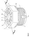
- eine perspektivische Ansicht einer erfindungsgemäßen Verschlussschraube,
- Fig. 2
- einen Schnitt entlang der Schnittlinie II-II in
Figur 1 , - Fig. 3
- einen Schnitt entlang der Schnittlinie III-III in
Figur 1 , - Fig. 4
- einen Schnitt entlang der Schnittlinie IV-IV in
Figur 1 , - Fig. 5
- eine perspektivische Ansicht einer weiteren Ausführung einer erfindungsgemäßen Verschlussschraube und
- Fig. 6
- einen Schnitt entlang der Schnittlinie VI-VI in
Fig. 5 .
- Fig. 1
- a perspective view of a screw plug according to the invention,
- Fig. 2
- a section along the section line II-II in
Figure 1 , - Fig. 3
- a section along the section line III-III in
Figure 1 , - Fig. 4
- a section along the section line IV-IV in
Figure 1 , - Fig. 5
- a perspective view of a further embodiment of a screw plug according to the invention and
- Fig. 6
- a section along the section line VI-VI in
Fig. 5 .
In den verschiedenen Figuren der Zeichnung sind gleiche Teile stets mit denselben Bezugszeichen versehen.In the various figures of the drawing, the same parts are always provided with the same reference symbols.
Zu der anschließenden Beschreibung wird beansprucht, dass die Erfindung nicht auf die Ausführungsbeispiele und dabei nicht auf alle oder mehrere Merkmale von beschriebenen Merkmalskombinationen beschränkt ist, vielmehr ist jedes einzelne Teilmerkmal des/jedes Ausführungsbeispiels auch losgelöst von allen anderen im Zusammenhang damit beschriebenen Teilmerkmalen für sich und auch in Kombination mit beliebigen Merkmalen eines anderen Ausführungsbeispiels von Bedeutung für den Gegenstand der Erfindung.In relation to the following description, it is claimed that the invention is not limited to the exemplary embodiments and not to all or several features of the described feature combinations; rather, each individual partial feature of the / each exemplary embodiment is also detached from all other partial features described in connection therewith also in combination with any features of another embodiment of importance for the subject matter of the invention.
Eine erfindungsgemäße Verschlussschraube für eine Austrittsöffnung eines fluidführenden Gehäuseteils umfasst einen im Querschnitt hohlzylindrischen, im Querschnitt kreisförmigen Einschraubabschnitt 1 mit einem Außengewinde 2, wobei an einem Ende des Einschraubabschnitts 1 ein gegenüber dem Einschraubabschnitt im Außendurchmesser vergrößerter Anlageflansch 3 angeformt ist.A screw plug according to the invention for an outlet opening of a fluid-carrying housing part comprises a screw-in section 1 with a hollow cylindrical cross-section and circular in cross-section with an
Der Einschraubabschnitt 1 und der Anlageflansch 3 sind vorteilhafterweise als einstückiges materialeinheitliches Kunststoff-Spritzgussteil hergestellt, so dass ein integrales Bauteil gebildet ist.The screw-in section 1 and the
Der Einschraubabschnitt 1 ist mit einem Boden 4 einendig verschlossen, und in Längsrichtung mittig durch den Anlageflansch 3 und den Einschraubabschnitt 1 ist eine Ausnehmung 6 als Innenangriff für ein Werkzeug ausgebildet, die am Boden 4 endet und dem Boden 4 gegenüberliegend eine Einstecköffnung 7 für den Eingriffsabschnitt des Werkzeugs aufweist.The screw-in section 1 is closed at one end with a
Der Anlageflansch 3 weist eine in Einschraubrichtung X gesehen vordere Anlagefläche 3a und an seinem äußeren Umfang einen Außenangriff 8 für ein Werkzeug auf. Dieser Außenangriff 8 ist insbesondere als Mehrkant und vorzugsweise als regelmäßiger Sechskant geformt. Im Übergangsbereich zwischen dem Anlageflansch 3 und dem Einschraubabschnitt 1 ist eine derartige Wandausbildung der Verschlussschraube vorhanden, dass für einen Abriss des Anlageflansches 3 im eingeschraubten Zustand des Einschraubabschnitts 1 unter Anlage des Anlageflansches 3 an einem Gehäuseteil aufgrund eines gegenüber einem zulässigen Anzugsmoment erhöhten Abrissmomentes ein Abrissbereich in Einschraubrichtung gesehen im Bereich des Endes des Einschraubabschnitts 1 und hinter dem Boden 4 ausgebildet ist, so dass der Kraftfluss innerhalb der Verschlussschraube beim Abriss nicht durch den Boden 4 verläuft, und wobei die Ausnehmung 6 mit dem Innenangriff eine derartige minimale Eingriffslänge L aufweist, dass ein Lösen der Verschlussschraube mittels eines in den Innenangriff 6 eingesetzten Werkzeuges möglich ist. Vorteilhafterweise wird die minimale Eingriffslänge L entsprechend DIN EN ISO 14579 vom Mai 2002 bemessen und ist insbesondere 3,6 mm lang. Hierbei befindet sich die minimale Eingriffslänge L vorteilhafterweise zwischen einer Bodenfläche 9 des Bodens 4 des Anlageflansches 3 und der Anlagefläche 3a des Anlageflansches 3.The
Bei einem Anzugsmoment von 17 Nm ist aufgrund der erfindungsgemäßen Ausgestaltung ein Sicherheitsfaktor von 2 für das Abreißmoment in Bezug auf das Anzugsmoment hinsichtlich eines Abrisses des Anlageflansches 3 ausreichend.With a tightening torque of 17 Nm, a safety factor of 2 for the tear-off torque with regard to the tightening torque with regard to the
Der Anlageflansch 3 weist eine innere Ausnehmung 12 auf, wobei eine äußere Umfangswandung 13 ausgebildet ist, die eine obere Flanschöffnung 14 umschließt. Eine Bodenfläche 9 der Ausnehmung 12 des Anlageflansches 3 ist der Flanschöffnung 14 gegenüberliegend ausgebildet. Die Bodenfläche 9 weist im Längsschnitt gesehen vorteilhafterweise eine konvex gebogene, in die Ausnehmung 12 gerichtete Form auf. Insbesondere liegt der in Einschraubrichtung X gesehen tiefste Bereich der Bodenfläche 9 unterhalb der Einstecköffnung 7 der Ausnehmung 6 des Innenangriffs und der in Einsteckrichtung gesehen hintere, d. h. obere Bereich der Bodenfläche 9 liegt an der Umfangswandung 13 oberhalb der Einstecköffnung 7 der Ausnehmung 6 des Innenangriffs.The
Der Boden 4 ist zweckmäßigerweise derart geformt, dass er einen in Einschraubrichtung X in Richtung auf das freie Ende des Einschraubabschnitts 1 versetzten mittleren Bodenabschnitt 4a aufweist und einen den Bodenabschnitt 4a umschließenden Bodenabschnitt 4b, der den mittleren Bodenabschnitt mit einer Umfangwandung 1a des Einschraubabschnitts 1 verbindet, und der vorteilhafterweise senkrecht zur Längsmittelachse des Einschraubabschnitts 1 verläuft. Der Bodenabschnitt 4a ist zum Beispiel in Richtung auf das freie Ende des Einschraubabschnitts 1 konvex ausgebildet. Durch die versetzte Anordnung kann der Bodenabschnitt 4a zum Beispiel zwischen den beiden Enden des Einschraubabschnitts 1 angeordnet sein. Der Bodenabschnitt 4a besitzt eine Breite B zwischen der Ausnehmung 6, die zweckmäßigerweise am Bodenabschnitt 4a endet, und seiner Umfangsfläche. Der Bodenabschnitt 4b ist über einen Wandungsabschnitt 9a, der die Bodenfläche 9 aufweist, mit dem Außenangriff 8 des Anlageflansches 3 verbunden. Dieser Wandungsabschnitt 9a ist, wie oben beschrieben, zweckmäßigerweise konvex ausgebildet.The
Weiterhin kann es zweckmäßig sein, wenn zwischen dem Anlageflansch 3 und dem Einschraubabschnitt 1 ein nutförmiger Aufnahmeabschnitt 18 für eine Umfangsdichtung 19 vorhanden ist. Dieser Aufnahmeabschnitt 18 besitzt vorzugsweise im Bereich seines Nutgrundes einen Außendurchmesser, der kleiner ist als ein Kerndurchmesser des Außengewindes 2 des Einschraubabschnitts 1. Die Umfangsdichtung 19 ist insbesondere als O-Ring-Dichtung ausgebildet, deren Außendurchmesser größer ist als ein Gewinde-Außendurchmesser des Außengewindes 2.Furthermore, it can be expedient if a groove-shaped
Weiterhin kann es zweckmäßig sein, wenn in Einschraubrichtung X gesehen am in Einschraubrichtung X weisenden Ende des Anlageflansches 3 umfangsgemäß ein radial abstehender lippenartiger Fortsatz 20 angeformt ist. Bei Ausbildung als Mehrkant, zum Beispiel als Sechskant, ist dieser lippenartige Fortsatz 20 zwischen den jeweiligen Ecken des Mehrkants, zum Beispiel Außensechskants, vorhanden. Hierdurch wird die Anlagefläche des Anlageflansches 3 zwischen den Ecken des Mehrkants vergrößert, und der Fortsatz 20 ist insbesondere derart ausgebildet, dass der Außendurchmesser im Bereich des Fortsatzes 20 gleich dem Außendurchmesser im Bereich der gegenüberliegenden Ecken des Mehrkants, insbesondere Außensechskants, ist. Durch die Ausbildung als Außensechskant kann der erfindungsgemäße Einschraubabschnitt 1 mit üblichen Schraubenschlüsseln angezogen werden.Furthermore, it can be expedient if a radially protruding lip-
Weiterhin ist es erfindungsgemäß von Vorteil, wenn die innere Wand der Umfangswandung 13 des Anlageflansches 3 und der Stutzenabschnitt 16 des Innenangriffs 6 durch Versteifungsstege 21 verbunden sind, die zweckmäßigerweise an der inneren Bodenfläche 9 des Anlageflansches 3 angeformt sind. Vorteilhafterweise sind die Versteifungsstege 21 umfangsgemäß gleichmäßig verteilt angeordnet. Bei einer Ausbildung des Außenangriffs 8 zum Beispiel als Sechskant sind sechs, vorzugsweise zwölf Versteifungsstege 21 vorhanden, von denen jeweils sechs Versteifungsstege 21 in den Ecken des Sechskants enden und jeweils bei der Ausbildung mit zwölf Versteifungsstegen 21 mittig zwischen den Ecken des Sechskants weiterer Versteifungsstege 21 verlaufen. Die Versteifungsstege 21 enden einerseits mit ihrer Oberkante 21a an der oberen Flanschöffnung 14 und andererseits an der Einstecköffnung 7, so dass die Versteifungsstege 21 mit ihrer Oberkante 21a nach innen schräg geneigt verlaufen.Furthermore, it is advantageous according to the invention if the inner wall of the
In den
Weiterhin ist in
Durch die erfindungsgemäße Ausbildung der Verschlussschraube wird erreicht, dass bei einem Abriss des Flanschabschnitts 3 der Einschraubabschnitt 1 mit dem Boden 4 innerhalb der Gewindebohrung des Gehäuseteils verbleibt, in das die Verschlussschraube eingeschraubt ist, so dass ein definierter Austritt des Fluids durch die Gewindegänge und insbesondere durch einen gebildeten Leckagepfad gegeben ist. Hierbei kann es von Vorteil sein, wenn in der Umfangsfläche des Einschraubabschnitts 1 im Bereich des Außengewindes 2 mindestens ein axial verlaufender Leckagepfad in Form einer Leckagenut 23 ausgebildet ist, wodurch ein kontrollierter Fluidaustritt bewirkt werden kann. Es ist vorteilhaft, wenn ein vorhandener Leckagepfad am in Einschraubrichtung vorderen Ende des Einschraubabschnitts 1 beginnt und seine axiale Länge mindestens der Höhe von zwei Gewindegängen entspricht. Da erfindungsgemäß der Boden 4 unterhalb des Gewindeendes, d. h. gegenüber diesem in Einschraubrichtung X versetzt verläuft, wird im Übrigen ein sicherer Verschluss der Gehäuseöffnung gewährleistet, wobei durch die erfindungsgemäße Ausbildung sichergestellt ist, dass der nach dem Abriss verbleibende Teil der erfindungsgemäßen Verschlussschraube über den Innenangriff 6 herausgeschraubt werden kann. Bei einer erfindungsgemäßen Verschlussschraube beträgt vorzugsweise das Anziehdrehmoment 10 bis 17 Nm und das Abrissdrehmoment beträgt zweckmäßigerweise 34 Nm. Das LosDrehmoment beträgt beispielsweise mindestens 2,5 Nm.The inventive design of the screw plug ensures that if the
Zweckmäßigerweise beträgt beispielsweise das Verhältnis der Schlüsselweite W des Außenangriffs 8 zum Kerndurchmesser K des Außengewindes 2 W : DK = 1 : 0,85 bei einer Schlüsselweite von beispielsweise W = 24.For example, the ratio of the width across flats W of the
Bei einer erfindungsgemäßen Verschlussschraube beträgt die Höhe des Anlageflansches 3 beispielsweise 7 mm und die Höhe des Fortsatzes 20 beträgt beispielsweise 0,7 mm.In a screw plug according to the invention, the height of the
Eine erfindungsgemäße Verschlussschraube wird als Spritzgussteil vorzugsweise aus polymerem Material, insbesondere Polyphthalamide (PPA) hergestellt, wobei es sich hierbei insbesondere um ein glasfaserverstärktes Material mit insbesondere einem 50 %-igen Gewichtsanteil von Glasfasermaterial handelt. Das verwendete Polyphthalamid (PPA) ist hitzestabilisiert und besitzt eine hohe Zugfestigkeit.A screw plug according to the invention is produced as an injection-molded part preferably from polymer material, in particular polyphthalamides (PPA), this being in particular a glass fiber reinforced material with in particular a 50% weight fraction of glass fiber material. The polyphthalamide (PPA) used is heat stabilized and has a high tensile strength.
Die Erfindung ist nicht auf die dargestellten und beschriebenen Ausführungsbeispiele beschränkt, sondern umfasst auch alle im Sinne der Erfindung gleichwirkenden Ausführungen.
Claims (18)
- Closure screw for an outlet opening of housings which carry fluids, comprising a circular-cylindrical screw-in portion (1) with an outer thread (2), and comprising a bearing flange (3) at one end of the screw-in portion (1) that has an enlarged outer diameter in relation to the screw-in portion (1), wherein the screw-in portion (1) is formed with the bearing flange (3) as a one-piece, materially uniform plastic injection-moulding part, and the screw-in portion (1) is closed off at one end by a base (4), and a recess (6) serving as an inner engagement means for a tool extends centrally through the bearing flange (3) and the screw-in portion (1) in a longitudinal direction and ends at the base (4) and has, opposite the base (4), an insertion opening (7) for the tool, wherein the bearing flange (3) has, on its outer periphery, an outer engagement means (8) for a tool, wherein a peripheral inner recess (12) with a flange opening (14) is formed between the outer engagement means (8) and the inner engagement means (6), wherein the inner recess (12) is formed in such a way that an outer peripheral wall (13) which surrounds the upper flange opening (14) is formed and an inner base surface (9) of the flange (3) is formed, opposite the flange opening (14), in the bearing flange (3) between the inner engagement means (6) and the peripheral wall (13), and the insertion opening (7) of the inner engagement means (6) is arranged, as seen in the screw-in direction (X), set back in relation to the base surface (9) of the bearing flange (3), such that a connector portion (16) which projects from the base surface (9) in the direction of the flange opening (14) and ends below the flange opening (14) and surrounds the insertion opening (7) is formed, and, in the transition region between the bearing flange (3) and the screw-in portion (1), there is provided a wall formation such that, for breaking-off of the bearing flange (3) in the screwed-in state of the screw-in portion (1) and of the abutment of the bearing flange (3) owing to an increased break-off moment at the outer engagement means (8) in relation to the permissible tightening moment, there is formed, as seen in the screw-in direction (X), in the region of the at the end of the screw-in portion (1) and behind the base (4), a break-off region, such that the flow of force within the closure screw, in the event of breaking-off, does not pass through the base (4), wherein there is provided a minimum engagement length (L) of the recess (6) for the inner engagement such that loosening of the closure screw by means of a tool inserted into the inner engagement means (6) is possible.
- Closure screw according to Claim 1, characterized in that the minimum engagement length (L) is dimensioned according to DIN EN ISO 14579 of May 2002 and is in particular 2.9 mm.
- Closure screw according to Claim 1 or 2, characterized in that the minimum engagement length (L) is situated between the bearing surface (3a) of the bearing flange (3) and an inner base surface (11) of the inner engagement means (6).
- Closure screw according to one of Claims 1 to 3,
characterized in that the base (4) is shaped in such a way that it has a central base portion (4a), which is offset in the direction of the free end of the screw-in portion (1), and a base portion (4b), which surrounds said central base portion (4a) and is connected to a peripheral wall (1a) of the screw-in portion (1) and extends in particular perpendicularly to the longitudinal central axis. - Closure screw according to Claim 4,
characterized in that the base portion (4b) has a width B and is connected, via a wall portion (9a) having a convexly curved base surface (9) of the inner recess (12), to that region of the bearing flange (3) which has the outer engagement means (8), said region having a radial width A, wherein the width B is 20% to 30% greater than the width A. - Closure screw according to one of Claims 1 to 5, characterized in that the axial length of the inner engagement means (6) is configured such that, proceeding from its insertion opening (7), its inner base surface (11) is arranged in the region of the end of the screw-in portion (1) in such a way that the outer thread (2) ends, as seen in the screw-in direction (X), behind the inner base surface (11).
- Closure screw according to one of Claims 1 to 6, characterized in that a groove-shaped receiving portion (18) for a peripheral seal (19) is formed between the bearing flange (3) and the screw-in portion (1).
- Closure screw according to Claim 7,
characterized in that the receiving portion (18) has, in the region of its groove base, an outer diameter which is smaller than a core diameter of the outer thread (2) of the screw-in portion (1). - Closure screw according to Claim 7 or 8, characterized in that the peripheral seal (19) is in the form of an O-ring seal whose outer diameter is greater than a thread outer diameter of the outer thread (2).
- Closure screw according to one of Claims 1 to 9, characterized in that the outer engagement means (8) is formed as a polygon, in particular a regular hexagon.
- Closure screw according to Claim 10, characterized in that a radially projecting lip-like extension (20) is formed between the corners of the hexagon in a peripheral manner at that end of the bearing flange (3) which faces in the screw-in direction (X), wherein preferably the diameter of the lip-like extension (20) is equal to the outer diameter of the hexagon in the region of the oppositely situated corners thereof.
- Closure screw according to one of Claims 1 to 11, characterized in that the outer peripheral wall (13) of the bearing flange (3) and the connector portion (16) of the inner engagement means (6) are connected by stiffening webs (21) which are formed on the inner base surface (9) and which are arranged in a peripherally uniformly distributed manner.
- Closure screw according to Claim 12, characterized in that the stiffening webs (21) extend with their free upper edge (21a) in the opening plane of the flange opening (14) and are attached at their end opposite the peripheral wall (13) to a hollow-cylindrical extension (25) of the connector portion (16).
- Closure screw according to Claim 13, characterized in that the stiffening webs (21) extend with their upper edge (21a) in the opening plane of the flange opening (14) perpendicularly to the central longitudinal axis, and the extension (25) ends with its free end (26) in the opening plane of the flange opening (14) too.
- Closure screw according to one of Claims 12 to 14, characterized in that, in one embodiment of the outer engagement means (8) as a hexagon, there are formed twelve stiffening webs (21), of which in each case six stiffening webs (21) end in the oppositely situated corners of the hexagon and in each case six stiffening webs (21) are formed centrally between the corners of the hexagon.
- Closure screw according to one of Claims 1 to 15, characterized in that at least one axially extending leakage groove (23) is formed on the peripheral surface of the screw-in portion (1) in the region of the outer thread (2).
- Closure screw according to one of Claims 1 to 16, characterized in that the ratio W:DK of a width across flats W of the outer engagement means (8) to a core diameter DK of the outer thread (2) is 1:0.85.
- Closure screw according to one of Claims 1 to 17, characterized in that the closure screw consists of polyphthalamide (PPA), which is in particular glass fibre-reinforced.
Applications Claiming Priority (2)
| Application Number | Priority Date | Filing Date | Title |
|---|---|---|---|
| DE102015116301.2A DE102015116301A1 (en) | 2015-09-25 | 2015-09-25 | "Screw" |
| PCT/EP2016/069407 WO2017050490A1 (en) | 2015-09-25 | 2016-08-16 | Screw plug |
Publications (2)
| Publication Number | Publication Date |
|---|---|
| EP3353460A1 EP3353460A1 (en) | 2018-08-01 |
| EP3353460B1 true EP3353460B1 (en) | 2021-05-05 |
Family
ID=56802463
Family Applications (1)
| Application Number | Title | Priority Date | Filing Date |
|---|---|---|---|
| EP16757593.5A Active EP3353460B1 (en) | 2015-09-25 | 2016-08-16 | Screw plug |
Country Status (4)
| Country | Link |
|---|---|
| EP (1) | EP3353460B1 (en) |
| CN (1) | CN108139012B (en) |
| DE (1) | DE102015116301A1 (en) |
| WO (1) | WO2017050490A1 (en) |
Families Citing this family (7)
| Publication number | Priority date | Publication date | Assignee | Title |
|---|---|---|---|---|
| US20180292039A1 (en) * | 2017-04-06 | 2018-10-11 | Victor Kirilichin | Single Piece Expansion Sealing Plug |
| DE102017122301B3 (en) | 2017-09-26 | 2018-10-31 | Benteler Automobiltechnik Gmbh | Fuel distributor |
| CN108867801A (en) * | 2018-07-17 | 2018-11-23 | 广东安格尔橡塑科技有限公司 | A kind of sealed toilet flange |
| CN110822109B (en) * | 2018-08-08 | 2023-05-23 | 浙江三花智能控制股份有限公司 | Valve device |
| CN110375128A (en) * | 2019-07-01 | 2019-10-25 | 格力电器(合肥)有限公司 | A kind of valve and air-conditioning |
| EP4094921A1 (en) * | 2021-05-27 | 2022-11-30 | Stack Mold Plus UG (haftungsbeschränkt) | Device with seal for closing holes against the passage of a medium |
| DE102021209796A1 (en) | 2021-09-06 | 2023-03-09 | Zf Friedrichshafen Ag | Screw plug, in particular screw plug of an outlet opening of a housing |
Family Cites Families (16)
| Publication number | Priority date | Publication date | Assignee | Title |
|---|---|---|---|---|
| US3963322A (en) * | 1975-01-23 | 1976-06-15 | Ite Imperial Corporation | Torque controlling set screw for use with the cable of solderless connectors, or the like |
| US4518295A (en) * | 1983-06-20 | 1985-05-21 | Textron Inc. | Multi-part fastening nut, including jam nut |
| DE3431516A1 (en) * | 1984-08-28 | 1986-03-13 | Klöckner-Humboldt-Deutz AG, 5000 Köln | Threaded bush for the reinforcing cladding of an opening in a workpiece |
| ATE159085T1 (en) * | 1994-07-15 | 1997-10-15 | Limanin Establishment | TEAR-OFF SCREW |
| US6231286B1 (en) * | 1996-07-18 | 2001-05-15 | B & B Hardware, Inc. | Headed fastener with precisely calculated groove under head to accommodate O'ring sealing member as a self-sealing assembly |
| ATE199583T1 (en) * | 1998-08-18 | 2001-03-15 | Petri Gerhard Gmbh & Co Kg | TEAR-OFF HEAD SCREW |
| DE502007003243D1 (en) * | 2007-12-11 | 2010-05-06 | Nexans | shearbolt |
| DE102009018979A1 (en) * | 2009-04-25 | 2010-11-04 | Spang & Brands Gmbh | Breaking stopper for clogging a hose |
| US8534428B2 (en) * | 2009-07-06 | 2013-09-17 | Shimano Inc. | One piece hydraulic disc brake caliper with one way plumbing |
| DE102012023594B3 (en) * | 2012-12-01 | 2014-02-27 | Obo Bettermann Gmbh & Co. Kg | blind plug |
| US8911189B2 (en) * | 2013-02-26 | 2014-12-16 | Apical Industries, Inc. | Frangible fastener |
| DE102013101972A1 (en) | 2013-02-28 | 2014-08-28 | Linde Material Handling Gmbh | Sealing plug for attachment, particularly hydraulic attachment of liquid-guiding line in industrial truck, has thread for inserting in inner thread of attachment, where tool holder is completely arranged within thread |
| CN203430948U (en) * | 2013-08-14 | 2014-02-12 | 宁波恒力液压股份有限公司 | Cut-off type plug |
| CN104919226A (en) * | 2014-01-07 | 2015-09-16 | 株式会社小松制作所 | Structure for closing hole for hydraulic circuit |
| CN104214464A (en) * | 2014-09-12 | 2014-12-17 | 江苏培达塑料有限公司 | Pipeline stopper |
| CN204664097U (en) * | 2015-06-01 | 2015-09-23 | 余姚市久源液压技术有限公司 | A kind of hydraulic jack or pipeline threaded insert |
-
2015
- 2015-09-25 DE DE102015116301.2A patent/DE102015116301A1/en not_active Withdrawn
-
2016
- 2016-08-16 WO PCT/EP2016/069407 patent/WO2017050490A1/en unknown
- 2016-08-16 EP EP16757593.5A patent/EP3353460B1/en active Active
- 2016-08-16 CN CN201680055829.9A patent/CN108139012B/en active Active
Also Published As
| Publication number | Publication date |
|---|---|
| WO2017050490A1 (en) | 2017-03-30 |
| DE102015116301A1 (en) | 2017-03-30 |
| EP3353460A1 (en) | 2018-08-01 |
| CN108139012B (en) | 2020-08-21 |
| CN108139012A (en) | 2018-06-08 |
Similar Documents
| Publication | Publication Date | Title |
|---|---|---|
| EP3353460B1 (en) | Screw plug | |
| EP2049807B1 (en) | Device for fastening an add-on part and a support part at a distance from each other | |
| EP1828623B1 (en) | Device for fastening an add-on and a support at a distance from each other | |
| EP3025066B1 (en) | Blind rivet nut for the connection of two components | |
| WO2007025704A1 (en) | Gripping strip for a syringe featuring improved burst protection | |
| EP3565976B1 (en) | Device for limiting torque with three webs | |
| DE102014221266A1 (en) | Quick fastener, method for joining two components by means of the quick fastener and manufacturing method therefor | |
| EP2232089A1 (en) | Threaded insert and vehicle component | |
| WO2018010738A1 (en) | Device for securing to a component | |
| EP2982874B1 (en) | Screw dome for attaching a component | |
| EP0986451B1 (en) | Screwdriver adapter | |
| DE202008000574U1 (en) | connecting device | |
| DE102016212547A1 (en) | Device for fixing to a component and such a component | |
| DE102012107861A1 (en) | fastening device | |
| EP3347607B1 (en) | Ball joint comprising a protective cap and two-point linkage comprising a ball joint of this type | |
| EP3221598B1 (en) | Deformable body, and system comprising a deformable body and an anti-creepage ring | |
| EP3587729B1 (en) | Connection of two drill string elements of a drill string for earth drilling | |
| WO2020200776A1 (en) | Multipart adjustment element for a tolerance compensation assembly | |
| EP2064454B1 (en) | Fastening device | |
| EP2308403B1 (en) | Bone screw and system | |
| EP3626898B1 (en) | Profile pipe system | |
| DE102015000490A1 (en) | fastener | |
| DE102010055808A1 (en) | fastening device | |
| DE202021100496U1 (en) | Conical wire thread and its use, especially in combination with a screw or an installation spindle | |
| EP3537017A1 (en) | Valve |
Legal Events
| Date | Code | Title | Description |
|---|---|---|---|
| STAA | Information on the status of an ep patent application or granted ep patent |
Free format text: STATUS: THE INTERNATIONAL PUBLICATION HAS BEEN MADE |
|
| PUAI | Public reference made under article 153(3) epc to a published international application that has entered the european phase |
Free format text: ORIGINAL CODE: 0009012 |
|
| STAA | Information on the status of an ep patent application or granted ep patent |
Free format text: STATUS: REQUEST FOR EXAMINATION WAS MADE |
|
| 17P | Request for examination filed |
Effective date: 20180219 |
|
| AK | Designated contracting states |
Kind code of ref document: A1 Designated state(s): AL AT BE BG CH CY CZ DE DK EE ES FI FR GB GR HR HU IE IS IT LI LT LU LV MC MK MT NL NO PL PT RO RS SE SI SK SM TR |
|
| AX | Request for extension of the european patent |
Extension state: BA ME |
|
| RIN1 | Information on inventor provided before grant (corrected) |
Inventor name: ROSOWSKI, EVELIN Inventor name: HAGEN, HARALD Inventor name: KLEHR, ADRIAN Inventor name: BRANDT, JOSEF |
|
| DAV | Request for validation of the european patent (deleted) | ||
| DAX | Request for extension of the european patent (deleted) | ||
| GRAP | Despatch of communication of intention to grant a patent |
Free format text: ORIGINAL CODE: EPIDOSNIGR1 |
|
| STAA | Information on the status of an ep patent application or granted ep patent |
Free format text: STATUS: GRANT OF PATENT IS INTENDED |
|
| INTG | Intention to grant announced |
Effective date: 20201214 |
|
| GRAS | Grant fee paid |
Free format text: ORIGINAL CODE: EPIDOSNIGR3 |
|
| GRAA | (expected) grant |
Free format text: ORIGINAL CODE: 0009210 |
|
| STAA | Information on the status of an ep patent application or granted ep patent |
Free format text: STATUS: THE PATENT HAS BEEN GRANTED |
|
| AK | Designated contracting states |
Kind code of ref document: B1 Designated state(s): AL AT BE BG CH CY CZ DE DK EE ES FI FR GB GR HR HU IE IS IT LI LT LU LV MC MK MT NL NO PL PT RO RS SE SI SK SM TR |
|
| REG | Reference to a national code |
Ref country code: GB Ref legal event code: FG4D Free format text: NOT ENGLISH |
|
| REG | Reference to a national code |
Ref country code: CH Ref legal event code: EP |
|
| REG | Reference to a national code |
Ref country code: AT Ref legal event code: REF Ref document number: 1390232 Country of ref document: AT Kind code of ref document: T Effective date: 20210515 |
|
| REG | Reference to a national code |
Ref country code: IE Ref legal event code: FG4D Free format text: LANGUAGE OF EP DOCUMENT: GERMAN |
|
| REG | Reference to a national code |
Ref country code: DE Ref legal event code: R096 Ref document number: 502016012996 Country of ref document: DE |
|
| REG | Reference to a national code |
Ref country code: LT Ref legal event code: MG9D |
|
| PG25 | Lapsed in a contracting state [announced via postgrant information from national office to epo] |
Ref country code: BG Free format text: LAPSE BECAUSE OF FAILURE TO SUBMIT A TRANSLATION OF THE DESCRIPTION OR TO PAY THE FEE WITHIN THE PRESCRIBED TIME-LIMIT Effective date: 20210805 Ref country code: HR Free format text: LAPSE BECAUSE OF FAILURE TO SUBMIT A TRANSLATION OF THE DESCRIPTION OR TO PAY THE FEE WITHIN THE PRESCRIBED TIME-LIMIT Effective date: 20210505 Ref country code: FI Free format text: LAPSE BECAUSE OF FAILURE TO SUBMIT A TRANSLATION OF THE DESCRIPTION OR TO PAY THE FEE WITHIN THE PRESCRIBED TIME-LIMIT Effective date: 20210505 Ref country code: LT Free format text: LAPSE BECAUSE OF FAILURE TO SUBMIT A TRANSLATION OF THE DESCRIPTION OR TO PAY THE FEE WITHIN THE PRESCRIBED TIME-LIMIT Effective date: 20210505 |
|
| PG25 | Lapsed in a contracting state [announced via postgrant information from national office to epo] |
Ref country code: NO Free format text: LAPSE BECAUSE OF FAILURE TO SUBMIT A TRANSLATION OF THE DESCRIPTION OR TO PAY THE FEE WITHIN THE PRESCRIBED TIME-LIMIT Effective date: 20210805 Ref country code: PL Free format text: LAPSE BECAUSE OF FAILURE TO SUBMIT A TRANSLATION OF THE DESCRIPTION OR TO PAY THE FEE WITHIN THE PRESCRIBED TIME-LIMIT Effective date: 20210505 Ref country code: PT Free format text: LAPSE BECAUSE OF FAILURE TO SUBMIT A TRANSLATION OF THE DESCRIPTION OR TO PAY THE FEE WITHIN THE PRESCRIBED TIME-LIMIT Effective date: 20210906 Ref country code: RS Free format text: LAPSE BECAUSE OF FAILURE TO SUBMIT A TRANSLATION OF THE DESCRIPTION OR TO PAY THE FEE WITHIN THE PRESCRIBED TIME-LIMIT Effective date: 20210505 Ref country code: SE Free format text: LAPSE BECAUSE OF FAILURE TO SUBMIT A TRANSLATION OF THE DESCRIPTION OR TO PAY THE FEE WITHIN THE PRESCRIBED TIME-LIMIT Effective date: 20210505 Ref country code: IS Free format text: LAPSE BECAUSE OF FAILURE TO SUBMIT A TRANSLATION OF THE DESCRIPTION OR TO PAY THE FEE WITHIN THE PRESCRIBED TIME-LIMIT Effective date: 20210905 Ref country code: LV Free format text: LAPSE BECAUSE OF FAILURE TO SUBMIT A TRANSLATION OF THE DESCRIPTION OR TO PAY THE FEE WITHIN THE PRESCRIBED TIME-LIMIT Effective date: 20210505 Ref country code: GR Free format text: LAPSE BECAUSE OF FAILURE TO SUBMIT A TRANSLATION OF THE DESCRIPTION OR TO PAY THE FEE WITHIN THE PRESCRIBED TIME-LIMIT Effective date: 20210806 |
|
| REG | Reference to a national code |
Ref country code: NL Ref legal event code: MP Effective date: 20210505 |
|
| PG25 | Lapsed in a contracting state [announced via postgrant information from national office to epo] |
Ref country code: NL Free format text: LAPSE BECAUSE OF FAILURE TO SUBMIT A TRANSLATION OF THE DESCRIPTION OR TO PAY THE FEE WITHIN THE PRESCRIBED TIME-LIMIT Effective date: 20210505 |
|
| PG25 | Lapsed in a contracting state [announced via postgrant information from national office to epo] |
Ref country code: SK Free format text: LAPSE BECAUSE OF FAILURE TO SUBMIT A TRANSLATION OF THE DESCRIPTION OR TO PAY THE FEE WITHIN THE PRESCRIBED TIME-LIMIT Effective date: 20210505 Ref country code: SM Free format text: LAPSE BECAUSE OF FAILURE TO SUBMIT A TRANSLATION OF THE DESCRIPTION OR TO PAY THE FEE WITHIN THE PRESCRIBED TIME-LIMIT Effective date: 20210505 Ref country code: CZ Free format text: LAPSE BECAUSE OF FAILURE TO SUBMIT A TRANSLATION OF THE DESCRIPTION OR TO PAY THE FEE WITHIN THE PRESCRIBED TIME-LIMIT Effective date: 20210505 Ref country code: EE Free format text: LAPSE BECAUSE OF FAILURE TO SUBMIT A TRANSLATION OF THE DESCRIPTION OR TO PAY THE FEE WITHIN THE PRESCRIBED TIME-LIMIT Effective date: 20210505 Ref country code: DK Free format text: LAPSE BECAUSE OF FAILURE TO SUBMIT A TRANSLATION OF THE DESCRIPTION OR TO PAY THE FEE WITHIN THE PRESCRIBED TIME-LIMIT Effective date: 20210505 Ref country code: RO Free format text: LAPSE BECAUSE OF FAILURE TO SUBMIT A TRANSLATION OF THE DESCRIPTION OR TO PAY THE FEE WITHIN THE PRESCRIBED TIME-LIMIT Effective date: 20210505 Ref country code: ES Free format text: LAPSE BECAUSE OF FAILURE TO SUBMIT A TRANSLATION OF THE DESCRIPTION OR TO PAY THE FEE WITHIN THE PRESCRIBED TIME-LIMIT Effective date: 20210505 |
|
| REG | Reference to a national code |
Ref country code: DE Ref legal event code: R097 Ref document number: 502016012996 Country of ref document: DE |
|
| PLBE | No opposition filed within time limit |
Free format text: ORIGINAL CODE: 0009261 |
|
| STAA | Information on the status of an ep patent application or granted ep patent |
Free format text: STATUS: NO OPPOSITION FILED WITHIN TIME LIMIT |
|
| REG | Reference to a national code |
Ref country code: CH Ref legal event code: PL |
|
| PG25 | Lapsed in a contracting state [announced via postgrant information from national office to epo] |
Ref country code: MC Free format text: LAPSE BECAUSE OF FAILURE TO SUBMIT A TRANSLATION OF THE DESCRIPTION OR TO PAY THE FEE WITHIN THE PRESCRIBED TIME-LIMIT Effective date: 20210505 |
|
| 26N | No opposition filed |
Effective date: 20220208 |
|
| REG | Reference to a national code |
Ref country code: BE Ref legal event code: MM Effective date: 20210831 |
|
| GBPC | Gb: european patent ceased through non-payment of renewal fee |
Effective date: 20210816 |
|
| PG25 | Lapsed in a contracting state [announced via postgrant information from national office to epo] |
Ref country code: LI Free format text: LAPSE BECAUSE OF NON-PAYMENT OF DUE FEES Effective date: 20210831 Ref country code: CH Free format text: LAPSE BECAUSE OF NON-PAYMENT OF DUE FEES Effective date: 20210831 |
|
| PG25 | Lapsed in a contracting state [announced via postgrant information from national office to epo] |
Ref country code: IS Free format text: LAPSE BECAUSE OF FAILURE TO SUBMIT A TRANSLATION OF THE DESCRIPTION OR TO PAY THE FEE WITHIN THE PRESCRIBED TIME-LIMIT Effective date: 20210905 Ref country code: LU Free format text: LAPSE BECAUSE OF NON-PAYMENT OF DUE FEES Effective date: 20210816 Ref country code: AL Free format text: LAPSE BECAUSE OF FAILURE TO SUBMIT A TRANSLATION OF THE DESCRIPTION OR TO PAY THE FEE WITHIN THE PRESCRIBED TIME-LIMIT Effective date: 20210505 |
|
| PG25 | Lapsed in a contracting state [announced via postgrant information from national office to epo] |
Ref country code: IT Free format text: LAPSE BECAUSE OF FAILURE TO SUBMIT A TRANSLATION OF THE DESCRIPTION OR TO PAY THE FEE WITHIN THE PRESCRIBED TIME-LIMIT Effective date: 20210505 Ref country code: IE Free format text: LAPSE BECAUSE OF NON-PAYMENT OF DUE FEES Effective date: 20210816 Ref country code: GB Free format text: LAPSE BECAUSE OF NON-PAYMENT OF DUE FEES Effective date: 20210816 Ref country code: BE Free format text: LAPSE BECAUSE OF NON-PAYMENT OF DUE FEES Effective date: 20210831 |
|
| REG | Reference to a national code |
Ref country code: AT Ref legal event code: MM01 Ref document number: 1390232 Country of ref document: AT Kind code of ref document: T Effective date: 20210816 |
|
| PG25 | Lapsed in a contracting state [announced via postgrant information from national office to epo] |
Ref country code: AT Free format text: LAPSE BECAUSE OF NON-PAYMENT OF DUE FEES Effective date: 20210816 |
|
| PG25 | Lapsed in a contracting state [announced via postgrant information from national office to epo] |
Ref country code: HU Free format text: LAPSE BECAUSE OF FAILURE TO SUBMIT A TRANSLATION OF THE DESCRIPTION OR TO PAY THE FEE WITHIN THE PRESCRIBED TIME-LIMIT; INVALID AB INITIO Effective date: 20160816 |
|
| PG25 | Lapsed in a contracting state [announced via postgrant information from national office to epo] |
Ref country code: CY Free format text: LAPSE BECAUSE OF FAILURE TO SUBMIT A TRANSLATION OF THE DESCRIPTION OR TO PAY THE FEE WITHIN THE PRESCRIBED TIME-LIMIT Effective date: 20210505 |
|
| P01 | Opt-out of the competence of the unified patent court (upc) registered |
Effective date: 20230526 |
|
| PGFP | Annual fee paid to national office [announced via postgrant information from national office to epo] |
Ref country code: FR Payment date: 20230817 Year of fee payment: 8 |
|
| PGFP | Annual fee paid to national office [announced via postgrant information from national office to epo] |
Ref country code: DE Payment date: 20231026 Year of fee payment: 8 |