EP3353364B1 - Schieberahmen für türen oder fenster sowie tür oder fenster mit dem schieberahmen - Google Patents
Schieberahmen für türen oder fenster sowie tür oder fenster mit dem schieberahmen Download PDFInfo
- Publication number
- EP3353364B1 EP3353364B1 EP16794414.9A EP16794414A EP3353364B1 EP 3353364 B1 EP3353364 B1 EP 3353364B1 EP 16794414 A EP16794414 A EP 16794414A EP 3353364 B1 EP3353364 B1 EP 3353364B1
- Authority
- EP
- European Patent Office
- Prior art keywords
- sash
- glass
- sheet
- profile
- edge
- Prior art date
- Legal status (The legal status is an assumption and is not a legal conclusion. Google has not performed a legal analysis and makes no representation as to the accuracy of the status listed.)
- Active
Links
Images


Classifications
-
- E—FIXED CONSTRUCTIONS
- E06—DOORS, WINDOWS, SHUTTERS, OR ROLLER BLINDS IN GENERAL; LADDERS
- E06B—FIXED OR MOVABLE CLOSURES FOR OPENINGS IN BUILDINGS, VEHICLES, FENCES OR LIKE ENCLOSURES IN GENERAL, e.g. DOORS, WINDOWS, BLINDS, GATES
- E06B3/00—Window sashes, door leaves, or like elements for closing wall or like openings; Layout of fixed or moving closures, e.g. windows in wall or like openings; Features of rigidly-mounted outer frames relating to the mounting of wing frames
- E06B3/02—Wings made completely of glass
- E06B3/025—Wings made completely of glass consisting of multiple glazing units
-
- E—FIXED CONSTRUCTIONS
- E06—DOORS, WINDOWS, SHUTTERS, OR ROLLER BLINDS IN GENERAL; LADDERS
- E06B—FIXED OR MOVABLE CLOSURES FOR OPENINGS IN BUILDINGS, VEHICLES, FENCES OR LIKE ENCLOSURES IN GENERAL, e.g. DOORS, WINDOWS, BLINDS, GATES
- E06B3/00—Window sashes, door leaves, or like elements for closing wall or like openings; Layout of fixed or moving closures, e.g. windows in wall or like openings; Features of rigidly-mounted outer frames relating to the mounting of wing frames
- E06B3/66—Units comprising two or more parallel glass or like panes permanently secured together
- E06B3/663—Elements for spacing panes
- E06B3/66309—Section members positioned at the edges of the glazing unit
- E06B3/66342—Section members positioned at the edges of the glazing unit characterised by their sealed connection to the panes
-
- E—FIXED CONSTRUCTIONS
- E06—DOORS, WINDOWS, SHUTTERS, OR ROLLER BLINDS IN GENERAL; LADDERS
- E06B—FIXED OR MOVABLE CLOSURES FOR OPENINGS IN BUILDINGS, VEHICLES, FENCES OR LIKE ENCLOSURES IN GENERAL, e.g. DOORS, WINDOWS, BLINDS, GATES
- E06B7/00—Special arrangements or measures in connection with doors or windows
- E06B7/16—Sealing arrangements on wings or parts co-operating with the wings
- E06B7/22—Sealing arrangements on wings or parts co-operating with the wings by means of elastic edgings, e.g. elastic rubber tubes; by means of resilient edgings, e.g. felt or plush strips, resilient metal strips
Definitions
- This invention relates to a sash for doors or windows.
- This invention also relates to a door or window obtained with the sash. More specifically, this invention is used for a sash for tilt or turn doors or windows.
- the design comprises two essential components: the so-called double glazing unit and the supporting frame for the double glazing unit and the functional accessories relating to the correct assembly and use of the sash formed.
- the double glazing unit comprises:
- the frame which mounts the double glazing comprises:
- This frame interacts with the fixed counterframe applied to the opening of the room in which the sash is mounted.
- the fixed counterframe has a profile and accessories which share the accessories present on the frame of the sash.
- WO 2010/097776 discloses a sash for sliding doors or windows comprising a rigid profile, forming a frame inside the main body, for each side of the main body itself and designed to be accommodated stably in an housing through fastening means according to the preamble of claim 1.
- EP 0 937 856 discloses a sash for doors or windows comprises a an internal metal frame having a closed square tubular profile glued to the glass on one side by a lower extension fitted with an anti UV adhesive on the inside of the glass.
- the tubular profile itself is only supported and not immersed in gluing components interposed with the glass.
- a rubber block is housed inside the cavity of the double glazing unit (associated on both sides only to the inner part of the sheets of glass) equipped with a shaped seat which houses, at least partially, in slidable coupling mode (before assembly on the double glazing unit) a complete metal profile configured to define both the seats for housing the control and operating accessories and the lateral actuation accessories such as a handle which are connected by subsequent machining on one of the sheets of glass and on the rubber.
- the frame is located asymmetrically and rests fully on the largest sheet of glass with the relative adhesive glue, whilst the other side, the difference in distance is compensated by a greater use of structural component and/or glue.
- This embodiment of a sash has the drawback of reduced structural sealing; the frame is asymmetrical and has two different tubularities so it does not represent a structural component with mechanical sealing for the pair of sheets of glass and can be used only on pairs of sheets of glass of different dimensions, that is, with reduced adaptation to frames of different dimensions and types of opening.
- the sash using this frame must necessarily have a satin-finish machining on the edges of the outer surfaces of the sheet of glass to obscure the part of adhesive used to associate the part(s) of frame to the inner surfaces of the sheets of glass.
- Another need felt, in the solutions with glass on view, is also to cover the end areas or free edges of the sheets of glass, mainly for aesthetical reasons and, secondarily, also for structural technical reasons.
- edges of the sheets of glass are covered by adhesive strips or by satin-finish machining of the edges themselves.
- the satin-finish machining means that the appearance of the sash can longer be modified and it is necessary to replace it if different appearances are chosen.
- This invention has for an aim to provide a door or window sash that overcomes the above mentioned disadvantages of the prior art.
- the aim of this invention is to provide a sash for doors or windows which is able to maintain the operational reliability of the traditional type sashes combined with a good appearance.
- a further aim of this invention is to propose a sash for doors or windows which increases the possibility of changing the appearance of the sash in a fast, simple and inexpensive manner.
- the sash for doors or windows comprises a first and a second sheet of glass positioned facing each other and parallel to each other at a mutual distance.
- the sash also comprises a spacer and joining element interposed between two inner surfaces facing each other of the two sheets of glasses to define a first closed inner perimeter zone or chamber and a second open outer perimeter zone or cavity for each side defined by the pair of sheets of glass.
- the sash also comprises a structural sealing/adhesion component applied along the outer perimeter defined by the cavity.
- the structural component occupies a volume of the cavity which is able to allow contact of the structural component at least with the spacer element and with a part of the inner surfaces of the two sheets of glass.
- the sash also comprises at least an element for housing accessory components for supporting and/or operating the sash associated with the structural component, for each side defined by the first and second sheet of glass.
- each element is comprised of a rigid profile having, in cross section, at least one closed base side and two flaps each formed by a stretch perpendicular to the base side and a recessed stretch, parallel to the base side, to form a channel with an opening.
- the rigid profile is associated with the structural component at least along the outer surface of the base side.
- the rigid profile comprises an anchoring rib projecting from the outer surface of the base side and immersed in the structural component; the anchoring rib has, in cross section, a form of a keel extending with its vertex towards the spacer element.
- the sash also comprises a rigid plate, for at least one side of one of the first and second sheets of glass, having a first portion associated, by removable adhesion means to the edge of an outer surface of one of the sheets of glass, opposite the corresponding inner surface defining the cavity, for covering the edge.
- This sash structure allows an extremely high quality standard to be obtained, both from a technical and aesthetic point of view.
- the presence of the rigid plate makes the appearance of the sash flexible, as it is possible to modify and adapt the colours of the frame of the sash according the needs of the user, as well as covering functional parts of the inner compartment of the sash itself.
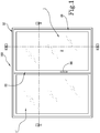
- the sash according to the invention labelled 1 in its entirety, is used for making doors or windows 100 with opening by turning or by turning and tilting and with single or double sash configurations.
- the doors or windows 100 of particular interest comprise a fixed frame 32 on which the sash 1 is articulated by hinges (not illustrated).
- the sash 1 may, therefore, rotate about a vertical axis and also (in the case of tilting movements) about a horizontal axis to move from a closed position to an open and vice versa.
- the sash 1, as described below, is equipped with control and operating components to allow the opening and closing configurations.
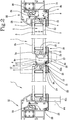
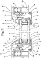
- the sash 1 for doors or windows comprises (see Figures 2 and 3 ) at least a first 2 and a second 3 sheet of glass positioned facing each other and parallel to each other at a mutual distance D.
- the sash 1 also comprises a spacer and joining element 4 interposed between two inner surfaces 2a, 3a facing each other of the two sheets of glasses 2, 3 to define a first closed inner perimeter zone or chamber 5 and a second open outer perimeter zone or cavity 6 for each side defined by the pair of sheets of glass 2, 3 (in this example there are four sides).
- the sash 1 comprises a structural sealing/adhesion component 7 applied along the outer perimeter defined by the cavity 6.
- the structural component 7 occupies a volume P of the cavity 6 which is able to allow contact of the structural component 1 at least with the spacer element 4 and with a part of the inner surface 2a, 3a of the two sheets of glass 2, 3.
- the sash 1 comprises, for each side defined by the first and second glass 2, 3, at least an element 8 for housing accessory components 9a, 9b, 9c, 9d for supporting and/or operating the sash 1 associated with the structural component 7.
- each element 8 is comprised of a rigid profile having, in cross section, at least one closed base side 9 and two flaps 10 and 11 each formed by a stretch 12 transversal to the base side 9 and a recessed stretch 13, parallel to the base side 9, to form a channel (in the form of a rotated "C") with an opening 14.
- the transversal stretch 12 is positioned perpendicular to the base side 9.
- the rigid profile is associated with the structural component 7 at least along the outer surface of the base side 10.
- the rigid profile 8 comprises at least one anchoring rib 15 projecting from the outer surface of the base side 9 and immersed in the structural component 7.
- the anchoring rib 15 has, in cross section, a form of a keel extending with its vertex towards the spacer element 4.
- the sash 1 comprises a rigid plate 20 (independent), for at least one side of one of the first 2 and second 3 sheets of glass (in the case illustrated, the one indicated with the numeral 2), having at least a first portion 21 associated, by removable adhesion means 22 to the edge of an outer surface 2b of one of the sheets of glass 2, 3, opposite the corresponding inner surface 2a, defining the cavity 6, for covering at least the edge.
- a cover which can be replaced, is applied on at least an outer edge side of one of the sheets of glass (in particular, the one to be fitted inside the room in which the sash is mounted), directly on the glass surface.
- the sash 1 comprises a rigid plate 20 for each side of one of the first 2 and second 3 sheets of glass to cover the outer edge perimeter of the first 2 or second 3 sheet of glass, to be fitted inside the room in which the sash 1 is mounted.
- the outer surface of a sheet of glass 2 is "edged" by a cover of the desired colour.
- the cover may be applied during assembly of the sash 1 or also when the sash 1 is already assembled and just before being applied on the fixed frame 32, without necessarily dismantling structural components of the sash 1.
- the rigid plate 20 comprises a second portion 23 protruding in a flag-like manner from the edge of the sheet of glass 2 and parallel towards the outside of the sheet of glass 2.
- the second portion 23 of the rigid plate 20 may be present for covering more of the parts of the volume of the cavity 6 of the sash 1 in which there are functional components.
- the plate 20 may be structured like a simple cover of the outer edge of the sheet of glass 2 or 3, that is, with only the first portion 21, or in a combined version with the second portion 23 which forms a sort of larger covering wing and, at the same time, a technical component for supporting sealing elements or elements for controlling operation of the sash 1.
- the rigid plate 20 has the first portion 21 equipped with a seat 24 having an inner volume for partially containing the removable adhesion means 22.
- the removable adhesion means 22 are interposed between the inner part of the seat 24 and a stretch of the outer surface 2b of the edge of the first sheet of glass 2.
- the removable adhesion means 22 comprise a strip of two-sided adhesive material.
- the strip has a thickness configured for engaging the internal volume of the seat 24, but without protruding from the edge of the seat 24.
- the seat 24 consists of a profile (illustrated in the drawing as a non-limiting example with a substantially "C" shape) with opening towards the glass surface 2b of the sheet of glass 2.
- the removable adhesion means 22 comprise a strip of removable adhesive applied between the seat 24 of the rigid plate 20 and the edge of the first sheet of glass 2.
- the first and the second 2 and 3 sheet of glass have equal perimeter dimensions (see Figures 2 and 3 ).
- the structural component 7 occupies the entire volume of the cavity 6 defined.
- the rigid profile 8 is positioned protruding from the cavity 6.
- the rigid plate 20 has a free end of the second portion 23 equipped with a profile 25 for coupling with a seal 26.
- the profile is obtained on the surface of the second portion 23 facing, in use, towards the cavity 6.
- the rigid plate 20 has the second portion 23 equipped with at least one through seat 27 for the coupling and support of a member 9d (handle) for controlling the sash 1.
- the presence of the second portion 23 of the rigid plate 20 also has the aim of supporting the appearance with a more strictly technical auxiliary function of supporting and positioning technical accessories.
- the sash 1 also comprises a rear covering profile 28 associated, through removable adhesion means 39, with each edge of the outer surface 3b, 2b of the other sheet of glass 3, 2 (in this case, the sheet of glass with the numeral 3).
- the profile 28 has:
- This further profile 29 may complete, from a technical point of view, the covering of the sash 1 on the outer side the room and with regards to the outer seal in combination with the fixed frame 32.
- the containment element 8 has an extension or hook-shaped elastic joint 80 of the base side 9 extending towards the rear side of the sash 1.
- the rear covering comprises a profile 81 with thermal insulation properties having a protrusion 82 configured to be coupled, in a removable fashion (and through a hinge-like rotation), to the elastic joint 80.
- the profile 81 (thermal break element) is rapidly and precisely associated with the housing element 8 and, thanks to the hinge-like coupling, can be positioned on the outer surface 3b of the sheet of glass 3 in the proximity of the edge of the sheet of glass.
- the profile 81 in effect, has a second portion 83 configured to associate with the outer surface 3b using adhesion means.
- the rear covering also comprises a further plate profile 84 designed for coupling both with the profile 81 (in such a way as to cover the profile 81) and to associate (again with adhesion means) with the outer surface 3a of the sheet of glass 3 again in the proximity of the edge.
- the structural component 7 has sealing characteristics to allow a greater seal of the inner chamber 5 and adhesion characteristics to increase the mechanical characteristics of the double glazing unit formed.
- each cavity 6 present on the corresponding double glazing structure formed has a single rigid profile 8 (single piece) extending for the entire length of the side.
- the rigid profile 8 comprises at least one anchoring rib 15 projecting from the outer surface of the base side 9 and immersed in the structural component 7.
- This rib 15 allows the mechanical seal to be increased between the structural component 7 and the rigid profile 8 in order to guarantee a system for supporting the accessory components which is extremely safe.
- the anchoring rib 15 is immersed completely in the structural component 7 for an extension at least at least equal to half of a thickness defined by the structural component 7 (inside the cavity 6).
- the anchoring rib 15 has the respective longitudinal axes of extension positioned perpendicular relative to the base side 9 of the housing element 8.
- anchoring rib 15 has a profile provided with a tubular chamber 16 to define a form of keel with a partly wedge-shaped cross section of extension.
- the anchoring rib 15 has the relative contact base with the base side 9 of the housing element 8 with a width at least equal to a third of the length of the base side 9.
- the rigid profile 8 is associated with the structural component 7 in a position asymmetrical relative to the two sheets of glass 2, 3, that is, in a position which is off centre with respect to the width of the cavity 6 corresponding to the distance D between the two sheets of glass 2, 3.
- first 2 and the second 3 sheet of glass have equal perimeter dimensions.
- the structural component 7 occupies the entire volume of the cavity 6 defined.
- structural component 7 in this configuration may protrude from the cavity 6 until wrapping around at least one of the ends of the two sheets of glass 2 or 3.
- the rigid profile 8 is positioned protruding from the cavity 6.
- the rigid profile 8 preferably is, but not necessarily, positioned off-centre relative to the cavity 6.
- the rigid profile 8 is positioned with partial overlapping of a free end of one of the sheets of glass 2, 3 wrapped in the structural component 7.
- the rib 15 of the rigid profile 8 has an extension S15 calculated from the outer surface of the base side 9 at least greater than the depth P8 of the channel defined by the flaps 10, 11 of the rigid profile 8.
- the channel of the rigid profile 8 houses operating components such as an operating rod 9a (see dashed line in Figure 2 and solid line in Figure 3 ) which are slidable inside the channel.
- the operating rod 9a may be associated, for example, to constraining elements 9b such as bosses (see Figure 2 ) interacting with striker elements constrained to the fixed frame 32 (not illustrated herein).
- Elements 9c for constraining the rod 9a are applied on the rod 9a for connecting with the control handle 9d located outside the sash 1 and supported by the second portion 23 of the plate 20.
- This invention also provides a fixture for making doors or windows.
- the fixture comprises at least:
- the rigid plate 20 of the sash 1 has a sealing gasket 26 at the free end of the second portion 23 in contact with at least a contact surface 32a, in the closed configuration of the sash 1.
- a first contact surface 32a is formed by an outer surface of the frame 32.
- another contact surface may be a component 32b of the auxiliary sash 1' (see Figure 2 ), without thereby limiting the scope of protection of this invention.
- Figure 5 shows in detail a central part of a door or window with two sashes (main and secondary).
- the secondary sash (in this case labelled 1') comprises the housing element 8 having a hook-shaped elastically compliant extension 90 along the base side 9.
- the hook-shaped end of the extension 90 is engaged in a protrusion 92 forming part of a profile 91 with thermal insulation properties.
- the protrusion 92 is designed for coupling, in a removable fashion (and through a hinge-like rotation), at the hook-shaped end.
- the profile 91 also has two half-bodies 93 and 94 extending towards the rear part of the sash 1'. These half-bodies 93 or 94 are positioned, in use, on opposite sides of the shank 95 of a stiffening body 96 with a T-shaped cross-section.
- the head of the body 96 is housed in a rear covering profile 97 configured for covering the rear central zones between the two sashes.
- the profile 97 has two seats 97a and 97b for housing the ends of the two half-bodies 93 and 94.
- the thermal break profile 91, the covering profile 97 and the stiffening body 96 are joined stably together by a screw element 98 passing transversely between the profile 91 and the shank 95 of the body 96.
- this group of components move with the sash 1', whilst during closing they allow the correct contact of the components of the main sash 1.
- the preset aims are fully achieved with a sash structured in this way.
- the sash has an extremely reduced number of components and, consequently, a fast and easy assembly with a reduction in overall costs. Moreover, this structure makes it possible to adapt the sash to many types of fixed frames without having to change any type of component.
- a perimeter cover structured in such a way as to be interchangeable allows an aesthetic adaptation or a change in appearance of the visible front of the sash which is extremely convenient, simple and low cost.
- the cover may be used to support technical components in a rational manner and combined with the aim of the appearance, in such a way as to optimise the structure of the sash as a whole.
Landscapes
- Engineering & Computer Science (AREA)
- Civil Engineering (AREA)
- Structural Engineering (AREA)
- Securing Of Glass Panes Or The Like (AREA)
Claims (11)
- Flügel für Türen oder Fenster, wobei der Flügel (1) umfasst:- mindestens eine erste (2) und eine zweite (3) Glasscheibe, die einander zugewandt und in einem gegenseitigen Abstand (D) parallel zueinander angeordnet sind;- ein Abstandshalter- und Verbindungselement (4), das zwischen zwei einander zugewandten Innenflächen (2a, 3a) der beiden Glasscheiben (2, 3) angeordnet ist, um eine erste geschlossene Innenumfangszone oder Kammer (5) und eine zweite offene Außenumfangszone oder Hohlraum (6) für jede Seite zu definieren, die durch das Paar Glasscheiben (2, 3) definiert ist;- eine strukturelle Dichtungs-/Klebekomponente (7), die entlang des durch den Hohlraum (6) definierten Außenumfangs aufgebracht ist; die strukturelle Komponente (7) nimmt ein Volumen (P) des Hohlraums (6) ein, das einen Kontakt der strukturellen Komponente (7) mindestens mit dem Abstandshalterelement (4) und mit einem Teil der Innenfläche (2a, 3a) der beiden Glasscheiben (2, 3) ermöglichen kann,dadurch gekennzeichnet, dass er umfasst:- mindestens ein Element (8) zum Aufnehmen von Zubehörteilen (9a, 9b, 9c, 9d) zum Tragen und/oder Bedienen des Flügels (1), der mit der strukturellen Komponente (7) assoziiert ist, für jede Seite, die durch die erste und die zweite Glasscheibe (2, 3) definiert ist; wobei jedes Element (8) aus einem starren Profil besteht, das im Querschnitt mindestens eine geschlossene Basisseite (9) und zwei Klappen (10, 11) aufweist, die jeweils durch ein Teilstück (12) quer zur Basisseite (9) und ein vertieftes Teilstück (13) parallel zur Basisseite gebildet sind, um einen Kanal mit einer Öffnung (14) zu bilden; wobei das starre Profil mindestens entlang der Außenfläche der Basisseite (10) mit der strukturellen Komponente (7) assoziiert ist; wobei das starre Profil (8) mindestens eine Verankerungsrippe (15) umfasst, die von der Außenfläche der Basisseite (9) absteht und in die strukturelle Komponente (7) eingetaucht ist; wobei die Verankerungsrippe (15) im Querschnitt eine Form eines Kiels aufweist, der sich mit dessen Scheitelpunkt in Richtung des Abstandshalterelements (4) erstreckt;- eine starre Platte (20) für mindestens eine Seite einer der ersten (2) und zweiten (3) Glasscheibe, aufweisend mindestens einen ersten Abschnitt (21), der durch entfernbare Klebemittel (22) mit der Kante einer Außenfläche (2b oder 3b) einer der Glasscheiben (2, 3) gegenüberliegend der entsprechenden Innenfläche (2a oder 3a), die den Hohlraum (6) definiert, assoziiert ist, um mindestens die Kante abzudecken; und wobei die starre Platte (20) einen zweiten Abschnitt (23) umfasst, der fahnenartig von der Kante der Glasscheibe (2, 3) absteht und parallel zur Außenseite der Glasscheibe (2, 3) verläuft.
- Flügel nach Anspruch 1, umfassend eine starre Platte (20) für jede Seite einer der ersten (2) und zweiten (3) Glasscheiben, um den seitlichen Umfang der ersten (2) oder zweiten (3) Glasscheibe abzudecken, um in einem Raum, in dem der Flügel (1) montiert ist, eingesetzt zu werden.
- Flügel nach einem der vorhergehenden Ansprüche, wobei die starre Platte (20) den ersten Abschnitt (21) aufweist, der mit einem Sitz (24) ausgestattet ist, der ein Innenvolumen zum teilweisen Enthalten der entfernbaren Klebemittel (22) aufweist; wobei die entfernbaren Klebemittel (22) zwischen dem inneren Teil des Sitzes (24) und einem Teilstück der Außenfläche (2b, 3b) der Kante der ersten (2) oder zweiten (3) Glasscheibe angeordnet ist.
- Flügel nach einem der vorhergehenden Ansprüche, wobei die entfernbaren Klebemittel (22) einen Streifen aus zweiseitig klebendem Material umfassen.
- Flügel nach einem der Ansprüche 1 bis 4, wobei die entfernbaren Klebemittel (22) einen Streifen aus entfernbarem Klebstoff umfassen, der zwischen dem Sitz (24) der starren Platte (20) und der Kante der ersten (2) oder zweiten (3) Glasscheibe aufgebracht ist.
- Flügel nach einem der vorhergehenden Ansprüche, wobei die erste (2) und die zweite (3) Glasscheibe gleiche Umfangsabmessungen aufweisen und wobei die strukturelle Komponente (7) mindestens das gesamte definierte Volumen des Hohlraums (6) einnimmt und das starre Profil (8) vom Hohlraum (6) abstehend angeordnet ist.
- Flügel nach einem der vorhergehenden Ansprüche, wobei die starre Platte (20) ein freies Ende des zweiten Abschnitts (23) aufweist, das mit einem Profil (25) zum Koppeln mit einer Abdichtung (26) ausgestattet ist.
- Flügel nach einem der vorhergehenden Ansprüche, wobei die starre Platte (20) den zweiten Abschnitt (23) aufweist, der mit mindestens einem durchgehenden Sitz (27) zum Koppeln und Tragen eines Elements (9d) zum Steuern des Flügels (1) ausgestattet ist.
- Flügel nach einem der vorhergehenden Ansprüche, umfassend ein hinteres Abdeckprofil (28), das durch entfernbare Klebemittel (39) mit jeder Kante der Außenfläche (3b, 2b) der anderen Glasscheibe (3, 2) assoziiert ist; wobei das Profil (28) einen ersten Abschnitt (29) in Kontakt mit der Kante der Glasscheibe (3, 2), und einen zweiten Abschnitt (30), der mindestens quer relativ zur Kante der Glasscheibe (3, 2) wegführend konfiguriert ist und einen dritten Abschnitt (31) aufweist, der über das freie Ende der Kante der Glasscheibe (3, 2) absteht.
- Vorrichtung zur Herstellung von Türen oder Fenstern, dadurch gekennzeichnet, dass sie mindestens umfasst:- einen Flügel (1) nach einem der Ansprüche 1 bis 9;- einen festen Rahmen (32), an dem der Flügel (1) angelenkt ist, um mindestens eine geschlossene Konfiguration, wobei der Flügel (1) mit dem festen Rahmen (32) in Kontakt steht, und eine offene Konfiguration zu definieren, wobei der Flügel (1) vom festen Rahmen (32) entfernt ist; wobei der Rahmen (32) mindestens einen inneren Umfangskanal (33) aufweist, der so positioniert werden kann, dass er dem starren Profil (8) des Flügels (1) in einer geschlossenen Konfiguration zugewandt ist, und mindestens eine Dichtung (34), die in einer geschlossenen Konfiguration des Flügels (1) mit einem der Abschnitte (29, 30, 31) des hinteren Profils (28) in Kontakt platziert wird.
- Vorrichtung nach Anspruch 10, wobei das starre Profil (8) des Flügels (1) am freien Ende des zweiten Abschnitts (23) eine Dichtung (26) aufweist, die mit einer Kontaktfläche (32a, 32b) in der geschlossenen Konfiguration des Flügels (1) in Kontakt steht.
Applications Claiming Priority (2)
| Application Number | Priority Date | Filing Date | Title |
|---|---|---|---|
| ITUB2015A003763A ITUB20153763A1 (it) | 2015-09-21 | 2015-09-21 | Anta per porte o finestre e serramento ottenuto con l'anta. |
| PCT/IB2016/055624 WO2017051323A1 (en) | 2015-09-21 | 2016-09-21 | Sash for doors or windows and door or window obtained with the sash |
Publications (2)
| Publication Number | Publication Date |
|---|---|
| EP3353364A1 EP3353364A1 (de) | 2018-08-01 |
| EP3353364B1 true EP3353364B1 (de) | 2020-03-18 |
Family
ID=54705769
Family Applications (1)
| Application Number | Title | Priority Date | Filing Date |
|---|---|---|---|
| EP16794414.9A Active EP3353364B1 (de) | 2015-09-21 | 2016-09-21 | Schieberahmen für türen oder fenster sowie tür oder fenster mit dem schieberahmen |
Country Status (5)
| Country | Link |
|---|---|
| US (1) | US10641033B2 (de) |
| EP (1) | EP3353364B1 (de) |
| CN (1) | CN108026751A (de) |
| IT (1) | ITUB20153763A1 (de) |
| WO (1) | WO2017051323A1 (de) |
Families Citing this family (3)
| Publication number | Priority date | Publication date | Assignee | Title |
|---|---|---|---|---|
| WO2020147909A1 (en) * | 2019-01-14 | 2020-07-23 | Vkr Holding A/S | Pivot roof window with sash comprising vacuum insulated glass unit overlapping bottom frame profile |
| CA3105840A1 (en) * | 2020-01-17 | 2021-07-17 | Vision Extrusions Group Limited | Window assembly for mitigating fluid ingress |
| FR3107027B1 (fr) * | 2020-02-11 | 2024-03-22 | Saint Gobain | Systeme de fixation d’un vitrage lateral de moyen de transport avec un verrou |
Family Cites Families (27)
| Publication number | Priority date | Publication date | Assignee | Title |
|---|---|---|---|---|
| US4496201A (en) * | 1982-07-23 | 1985-01-29 | Umc Industries, Inc. | Closure such as a glass door for a refrigeration or freezer |
| FR2572766A1 (fr) | 1984-11-08 | 1986-05-09 | Juillet Hubert | Double vitrage a cadre interieur autoportant |
| EP0228641A3 (de) | 1985-12-20 | 1988-04-06 | Marco Fratti | Zarge mit festem und/oder bewegbarem Flügel für Türen, Fenster und dergleichen |
| US4741127A (en) * | 1986-12-22 | 1988-05-03 | Ardco Inc. | Refrigerator door with thermal insulated outer frame |
| US4961975A (en) * | 1988-11-14 | 1990-10-09 | Walter Bejnar | Sealed glass unit |
| US4948206A (en) * | 1988-12-02 | 1990-08-14 | Ardco, Inc. | Refrigerator door assembly with decorative front trim panels |
| SE469800B (sv) | 1989-01-20 | 1993-09-13 | Termofrost Sweden Ab | Dörrbladsprofil |
| US4998382A (en) * | 1989-12-11 | 1991-03-12 | Ardco, Inc. | Insulated refrigerator door assembly with substantially all glass front doors |
| US5255473A (en) * | 1989-12-11 | 1993-10-26 | Ardco, Inc. | Refrigerator door assembly with stylized substantially all glass front |
| USRE35149E (en) * | 1990-09-20 | 1996-01-30 | Anthony's Manufacturing Company, Inc. | Railless refrigerator display door |
| US5584143A (en) | 1993-05-07 | 1996-12-17 | Tyler Refrigeration Corporation | Edge seal gasket assembly for a multiple glazing unit |
| PL331010A1 (en) | 1996-07-11 | 1999-06-21 | Manfred Woschko | Frameless door leaf or window sash with thermally insulating glazing and method of making same |
| DE19642175C2 (de) | 1996-10-12 | 2002-12-19 | Eckelt Glas Gmbh Steyr | Fenster mit einem Holzrahmen und einer Isolierglasscheibe |
| DE29812574U1 (de) | 1997-08-02 | 1998-11-05 | Vegla Vereinigte Glaswerke Gmbh, 52066 Aachen | Rahmenloser Fenster- oder Türflügel |
| DE19802663C2 (de) * | 1998-01-24 | 2001-11-22 | Saint Gobain | Fenster- oder Türflügel aus zwei Glasscheiben |
| US6637093B2 (en) | 1998-03-03 | 2003-10-28 | Anthony, Inc. | Method of assembling a display case door |
| US6318027B1 (en) * | 1998-03-03 | 2001-11-20 | New Anthony, Inc. | Display case door |
| US6148563A (en) * | 1999-03-25 | 2000-11-21 | Hussmann Corporation | Reach-in door for refrigerated merchandiser |
| US6318036B1 (en) * | 1999-11-12 | 2001-11-20 | Dayton Technologies, L.L.C. | Patio door assembly with extruded plastics components |
| IT1392872B1 (it) | 2009-02-26 | 2012-04-02 | Gsg Int Spa | Anta per infisso scorrevole. |
| AT511726B1 (de) | 2011-07-15 | 2013-05-15 | Alfons Oberhofer | Vorrichtung zum verschieben eines schiebeelements |
| IL218177A (en) | 2012-02-16 | 2016-03-31 | Klil Ind Ltd | Glazed closure for development and method of assembly |
| DE102012215297A1 (de) | 2012-08-29 | 2014-03-06 | Lindner Fassaden Gmbh | Aus Fassadenelementen zusammengesetzter Fassadenaufbau und Verfahren zum Ersetzen von einzelnen Fassadenelementen |
| ITBO20120566A1 (it) | 2012-10-17 | 2014-04-18 | Gsg Int Spa | Anta per porta o finestra. |
| CN103741872A (zh) | 2013-12-27 | 2014-04-23 | 沈阳远大科技创业园有限公司 | 幕墙用免副框玻璃面材 |
| EP3274538A1 (de) | 2015-03-25 | 2018-01-31 | Saint-Gobain Glass France | Fensterrahmen zum verbau einer isolierglaseinheit mit verbindungselement |
| ITUB20153774A1 (it) * | 2015-09-21 | 2017-03-21 | Gsg Int S P A | Anta per porte o finestre. |
-
2015
- 2015-09-21 IT ITUB2015A003763A patent/ITUB20153763A1/it unknown
-
2016
- 2016-09-21 WO PCT/IB2016/055624 patent/WO2017051323A1/en not_active Ceased
- 2016-09-21 EP EP16794414.9A patent/EP3353364B1/de active Active
- 2016-09-21 US US15/761,666 patent/US10641033B2/en not_active Expired - Fee Related
- 2016-09-21 CN CN201680054706.3A patent/CN108026751A/zh active Pending
Non-Patent Citations (1)
| Title |
|---|
| None * |
Also Published As
| Publication number | Publication date |
|---|---|
| WO2017051323A1 (en) | 2017-03-30 |
| US10641033B2 (en) | 2020-05-05 |
| ITUB20153763A1 (it) | 2017-03-21 |
| EP3353364A1 (de) | 2018-08-01 |
| US20180347257A1 (en) | 2018-12-06 |
| CN108026751A (zh) | 2018-05-11 |
Similar Documents
| Publication | Publication Date | Title |
|---|---|---|
| US5553420A (en) | Casement window | |
| KR200436903Y1 (ko) | 옆 바깥열기형 여닫이 창호 | |
| CA2849353C (en) | A frame for a window and a method for making a frame | |
| US10683688B2 (en) | Folding device with adjusting strip | |
| US10641033B2 (en) | Sash for doors or windows and door or window obtained with the sash | |
| EP3252249B1 (de) | Dachfenstererneuerungssystem und verfahren zur erneuerung eines dachfensters | |
| US12366108B2 (en) | Insulating glass element and sauna cabin comprising the insulating glass element | |
| EP3071775B1 (de) | Unsichtbarer fensterrahmen | |
| KR101905934B1 (ko) | 목재 외관을 갖는 창호 | |
| EP3353365B1 (de) | Flügel für türen oder fenster | |
| US4877076A (en) | Screen unit with built-in blind | |
| CN203742378U (zh) | 断热幕墙内开扇 | |
| EP3737819B1 (de) | Öffnungsfähige glasstruktur mit schutzprofilen | |
| CA2296157A1 (en) | Patio door with integral glazing frame | |
| RU2384422C2 (ru) | Остекление транспортных средств | |
| SI24024A (sl) | Okvir krila okna ali vrat z večslojno zasteklitvijo | |
| KR20140032203A (ko) | 미닫이 복합프레임 창호 구조 | |
| KR102086253B1 (ko) | 여닫창이 구비된 시스템 창호 | |
| GB2285828A (en) | Windows and doors | |
| GB2286005A (en) | Frames for windows and doors | |
| GB2315088A (en) | A glazing bar assembly for the connecting of double glazing units to form a Georgian style sash window | |
| EP1528211B8 (de) | Fensterflügel und Fenster mit demselben | |
| WO2019141670A1 (en) | Frameless casement with u-shaped profile | |
| IT201800002161U1 (it) | Sistema per serramenti a profilo universale | |
| GB2464559A (en) | Two part window frame |
Legal Events
| Date | Code | Title | Description |
|---|---|---|---|
| STAA | Information on the status of an ep patent application or granted ep patent |
Free format text: STATUS: UNKNOWN |
|
| STAA | Information on the status of an ep patent application or granted ep patent |
Free format text: STATUS: THE INTERNATIONAL PUBLICATION HAS BEEN MADE |
|
| PUAI | Public reference made under article 153(3) epc to a published international application that has entered the european phase |
Free format text: ORIGINAL CODE: 0009012 |
|
| STAA | Information on the status of an ep patent application or granted ep patent |
Free format text: STATUS: REQUEST FOR EXAMINATION WAS MADE |
|
| 17P | Request for examination filed |
Effective date: 20171030 |
|
| AK | Designated contracting states |
Kind code of ref document: A1 Designated state(s): AL AT BE BG CH CY CZ DE DK EE ES FI FR GB GR HR HU IE IS IT LI LT LU LV MC MK MT NL NO PL PT RO RS SE SI SK SM TR |
|
| AX | Request for extension of the european patent |
Extension state: BA ME |
|
| DAV | Request for validation of the european patent (deleted) | ||
| DAX | Request for extension of the european patent (deleted) | ||
| GRAP | Despatch of communication of intention to grant a patent |
Free format text: ORIGINAL CODE: EPIDOSNIGR1 |
|
| STAA | Information on the status of an ep patent application or granted ep patent |
Free format text: STATUS: GRANT OF PATENT IS INTENDED |
|
| INTG | Intention to grant announced |
Effective date: 20191010 |
|
| GRAS | Grant fee paid |
Free format text: ORIGINAL CODE: EPIDOSNIGR3 |
|
| GRAA | (expected) grant |
Free format text: ORIGINAL CODE: 0009210 |
|
| STAA | Information on the status of an ep patent application or granted ep patent |
Free format text: STATUS: THE PATENT HAS BEEN GRANTED |
|
| AK | Designated contracting states |
Kind code of ref document: B1 Designated state(s): AL AT BE BG CH CY CZ DE DK EE ES FI FR GB GR HR HU IE IS IT LI LT LU LV MC MK MT NL NO PL PT RO RS SE SI SK SM TR |
|
| REG | Reference to a national code |
Ref country code: GB Ref legal event code: FG4D |
|
| REG | Reference to a national code |
Ref country code: DE Ref legal event code: R096 Ref document number: 602016032162 Country of ref document: DE |
|
| REG | Reference to a national code |
Ref country code: AT Ref legal event code: REF Ref document number: 1246080 Country of ref document: AT Kind code of ref document: T Effective date: 20200415 Ref country code: IE Ref legal event code: FG4D |
|
| PG25 | Lapsed in a contracting state [announced via postgrant information from national office to epo] |
Ref country code: NO Free format text: LAPSE BECAUSE OF FAILURE TO SUBMIT A TRANSLATION OF THE DESCRIPTION OR TO PAY THE FEE WITHIN THE PRESCRIBED TIME-LIMIT Effective date: 20200618 Ref country code: FI Free format text: LAPSE BECAUSE OF FAILURE TO SUBMIT A TRANSLATION OF THE DESCRIPTION OR TO PAY THE FEE WITHIN THE PRESCRIBED TIME-LIMIT Effective date: 20200318 Ref country code: RS Free format text: LAPSE BECAUSE OF FAILURE TO SUBMIT A TRANSLATION OF THE DESCRIPTION OR TO PAY THE FEE WITHIN THE PRESCRIBED TIME-LIMIT Effective date: 20200318 |
|
| REG | Reference to a national code |
Ref country code: NL Ref legal event code: MP Effective date: 20200318 |
|
| PG25 | Lapsed in a contracting state [announced via postgrant information from national office to epo] |
Ref country code: GR Free format text: LAPSE BECAUSE OF FAILURE TO SUBMIT A TRANSLATION OF THE DESCRIPTION OR TO PAY THE FEE WITHIN THE PRESCRIBED TIME-LIMIT Effective date: 20200619 Ref country code: HR Free format text: LAPSE BECAUSE OF FAILURE TO SUBMIT A TRANSLATION OF THE DESCRIPTION OR TO PAY THE FEE WITHIN THE PRESCRIBED TIME-LIMIT Effective date: 20200318 Ref country code: LV Free format text: LAPSE BECAUSE OF FAILURE TO SUBMIT A TRANSLATION OF THE DESCRIPTION OR TO PAY THE FEE WITHIN THE PRESCRIBED TIME-LIMIT Effective date: 20200318 Ref country code: SE Free format text: LAPSE BECAUSE OF FAILURE TO SUBMIT A TRANSLATION OF THE DESCRIPTION OR TO PAY THE FEE WITHIN THE PRESCRIBED TIME-LIMIT Effective date: 20200318 Ref country code: BG Free format text: LAPSE BECAUSE OF FAILURE TO SUBMIT A TRANSLATION OF THE DESCRIPTION OR TO PAY THE FEE WITHIN THE PRESCRIBED TIME-LIMIT Effective date: 20200618 |
|
| REG | Reference to a national code |
Ref country code: LT Ref legal event code: MG4D |
|
| PG25 | Lapsed in a contracting state [announced via postgrant information from national office to epo] |
Ref country code: NL Free format text: LAPSE BECAUSE OF FAILURE TO SUBMIT A TRANSLATION OF THE DESCRIPTION OR TO PAY THE FEE WITHIN THE PRESCRIBED TIME-LIMIT Effective date: 20200318 |
|
| PG25 | Lapsed in a contracting state [announced via postgrant information from national office to epo] |
Ref country code: CZ Free format text: LAPSE BECAUSE OF FAILURE TO SUBMIT A TRANSLATION OF THE DESCRIPTION OR TO PAY THE FEE WITHIN THE PRESCRIBED TIME-LIMIT Effective date: 20200318 Ref country code: RO Free format text: LAPSE BECAUSE OF FAILURE TO SUBMIT A TRANSLATION OF THE DESCRIPTION OR TO PAY THE FEE WITHIN THE PRESCRIBED TIME-LIMIT Effective date: 20200318 Ref country code: EE Free format text: LAPSE BECAUSE OF FAILURE TO SUBMIT A TRANSLATION OF THE DESCRIPTION OR TO PAY THE FEE WITHIN THE PRESCRIBED TIME-LIMIT Effective date: 20200318 Ref country code: LT Free format text: LAPSE BECAUSE OF FAILURE TO SUBMIT A TRANSLATION OF THE DESCRIPTION OR TO PAY THE FEE WITHIN THE PRESCRIBED TIME-LIMIT Effective date: 20200318 Ref country code: PT Free format text: LAPSE BECAUSE OF FAILURE TO SUBMIT A TRANSLATION OF THE DESCRIPTION OR TO PAY THE FEE WITHIN THE PRESCRIBED TIME-LIMIT Effective date: 20200812 Ref country code: SM Free format text: LAPSE BECAUSE OF FAILURE TO SUBMIT A TRANSLATION OF THE DESCRIPTION OR TO PAY THE FEE WITHIN THE PRESCRIBED TIME-LIMIT Effective date: 20200318 Ref country code: SK Free format text: LAPSE BECAUSE OF FAILURE TO SUBMIT A TRANSLATION OF THE DESCRIPTION OR TO PAY THE FEE WITHIN THE PRESCRIBED TIME-LIMIT Effective date: 20200318 Ref country code: IS Free format text: LAPSE BECAUSE OF FAILURE TO SUBMIT A TRANSLATION OF THE DESCRIPTION OR TO PAY THE FEE WITHIN THE PRESCRIBED TIME-LIMIT Effective date: 20200718 |
|
| REG | Reference to a national code |
Ref country code: AT Ref legal event code: MK05 Ref document number: 1246080 Country of ref document: AT Kind code of ref document: T Effective date: 20200318 |
|
| REG | Reference to a national code |
Ref country code: DE Ref legal event code: R097 Ref document number: 602016032162 Country of ref document: DE |
|
| PLBE | No opposition filed within time limit |
Free format text: ORIGINAL CODE: 0009261 |
|
| STAA | Information on the status of an ep patent application or granted ep patent |
Free format text: STATUS: NO OPPOSITION FILED WITHIN TIME LIMIT |
|
| PG25 | Lapsed in a contracting state [announced via postgrant information from national office to epo] |
Ref country code: AT Free format text: LAPSE BECAUSE OF FAILURE TO SUBMIT A TRANSLATION OF THE DESCRIPTION OR TO PAY THE FEE WITHIN THE PRESCRIBED TIME-LIMIT Effective date: 20200318 Ref country code: ES Free format text: LAPSE BECAUSE OF FAILURE TO SUBMIT A TRANSLATION OF THE DESCRIPTION OR TO PAY THE FEE WITHIN THE PRESCRIBED TIME-LIMIT Effective date: 20200318 Ref country code: DK Free format text: LAPSE BECAUSE OF FAILURE TO SUBMIT A TRANSLATION OF THE DESCRIPTION OR TO PAY THE FEE WITHIN THE PRESCRIBED TIME-LIMIT Effective date: 20200318 |
|
| 26N | No opposition filed |
Effective date: 20201221 |
|
| PG25 | Lapsed in a contracting state [announced via postgrant information from national office to epo] |
Ref country code: PL Free format text: LAPSE BECAUSE OF FAILURE TO SUBMIT A TRANSLATION OF THE DESCRIPTION OR TO PAY THE FEE WITHIN THE PRESCRIBED TIME-LIMIT Effective date: 20200318 |
|
| REG | Reference to a national code |
Ref country code: CH Ref legal event code: PL |
|
| GBPC | Gb: european patent ceased through non-payment of renewal fee |
Effective date: 20200921 |
|
| PG25 | Lapsed in a contracting state [announced via postgrant information from national office to epo] |
Ref country code: SI Free format text: LAPSE BECAUSE OF FAILURE TO SUBMIT A TRANSLATION OF THE DESCRIPTION OR TO PAY THE FEE WITHIN THE PRESCRIBED TIME-LIMIT Effective date: 20200318 |
|
| REG | Reference to a national code |
Ref country code: BE Ref legal event code: MM Effective date: 20200930 |
|
| PG25 | Lapsed in a contracting state [announced via postgrant information from national office to epo] |
Ref country code: LU Free format text: LAPSE BECAUSE OF NON-PAYMENT OF DUE FEES Effective date: 20200921 |
|
| PG25 | Lapsed in a contracting state [announced via postgrant information from national office to epo] |
Ref country code: IE Free format text: LAPSE BECAUSE OF NON-PAYMENT OF DUE FEES Effective date: 20200921 Ref country code: GB Free format text: LAPSE BECAUSE OF NON-PAYMENT OF DUE FEES Effective date: 20200921 Ref country code: LI Free format text: LAPSE BECAUSE OF NON-PAYMENT OF DUE FEES Effective date: 20200930 Ref country code: BE Free format text: LAPSE BECAUSE OF NON-PAYMENT OF DUE FEES Effective date: 20200930 Ref country code: CH Free format text: LAPSE BECAUSE OF NON-PAYMENT OF DUE FEES Effective date: 20200930 |
|
| PG25 | Lapsed in a contracting state [announced via postgrant information from national office to epo] |
Ref country code: TR Free format text: LAPSE BECAUSE OF FAILURE TO SUBMIT A TRANSLATION OF THE DESCRIPTION OR TO PAY THE FEE WITHIN THE PRESCRIBED TIME-LIMIT Effective date: 20200318 Ref country code: MT Free format text: LAPSE BECAUSE OF FAILURE TO SUBMIT A TRANSLATION OF THE DESCRIPTION OR TO PAY THE FEE WITHIN THE PRESCRIBED TIME-LIMIT Effective date: 20200318 Ref country code: CY Free format text: LAPSE BECAUSE OF FAILURE TO SUBMIT A TRANSLATION OF THE DESCRIPTION OR TO PAY THE FEE WITHIN THE PRESCRIBED TIME-LIMIT Effective date: 20200318 |
|
| PG25 | Lapsed in a contracting state [announced via postgrant information from national office to epo] |
Ref country code: MK Free format text: LAPSE BECAUSE OF FAILURE TO SUBMIT A TRANSLATION OF THE DESCRIPTION OR TO PAY THE FEE WITHIN THE PRESCRIBED TIME-LIMIT Effective date: 20200318 Ref country code: MC Free format text: LAPSE BECAUSE OF FAILURE TO SUBMIT A TRANSLATION OF THE DESCRIPTION OR TO PAY THE FEE WITHIN THE PRESCRIBED TIME-LIMIT Effective date: 20200318 Ref country code: AL Free format text: LAPSE BECAUSE OF FAILURE TO SUBMIT A TRANSLATION OF THE DESCRIPTION OR TO PAY THE FEE WITHIN THE PRESCRIBED TIME-LIMIT Effective date: 20200318 |
|
| P01 | Opt-out of the competence of the unified patent court (upc) registered |
Effective date: 20230508 |
|
| PGFP | Annual fee paid to national office [announced via postgrant information from national office to epo] |
Ref country code: DE Payment date: 20250926 Year of fee payment: 10 |
|
| PGFP | Annual fee paid to national office [announced via postgrant information from national office to epo] |
Ref country code: IT Payment date: 20250923 Year of fee payment: 10 |
|
| PGFP | Annual fee paid to national office [announced via postgrant information from national office to epo] |
Ref country code: FR Payment date: 20250925 Year of fee payment: 10 |