EP3352449B1 - Dispositif électronique et procédé photographique - Google Patents
Dispositif électronique et procédé photographique Download PDFInfo
- Publication number
- EP3352449B1 EP3352449B1 EP16848839.3A EP16848839A EP3352449B1 EP 3352449 B1 EP3352449 B1 EP 3352449B1 EP 16848839 A EP16848839 A EP 16848839A EP 3352449 B1 EP3352449 B1 EP 3352449B1
- Authority
- EP
- European Patent Office
- Prior art keywords
- display
- data
- electronic device
- image
- processor
- Prior art date
- Legal status (The legal status is an assumption and is not a legal conclusion. Google has not performed a legal analysis and makes no representation as to the accuracy of the status listed.)
- Active
Links
- 238000000034 method Methods 0.000 title claims description 58
- 230000004044 response Effects 0.000 claims description 74
- 238000004891 communication Methods 0.000 claims description 41
- 230000014509 gene expression Effects 0.000 claims description 23
- 230000006870 function Effects 0.000 description 62
- 238000006243 chemical reaction Methods 0.000 description 16
- 230000015572 biosynthetic process Effects 0.000 description 14
- 238000003786 synthesis reaction Methods 0.000 description 14
- 238000010586 diagram Methods 0.000 description 11
- 230000008569 process Effects 0.000 description 9
- 230000005540 biological transmission Effects 0.000 description 8
- 230000001413 cellular effect Effects 0.000 description 8
- 230000036541 health Effects 0.000 description 6
- 230000008859 change Effects 0.000 description 5
- 238000001514 detection method Methods 0.000 description 5
- 230000000694 effects Effects 0.000 description 5
- 238000005516 engineering process Methods 0.000 description 3
- 230000003287 optical effect Effects 0.000 description 3
- 239000008280 blood Substances 0.000 description 2
- 210000004369 blood Anatomy 0.000 description 2
- 238000002591 computed tomography Methods 0.000 description 2
- 239000000470 constituent Substances 0.000 description 2
- 239000000446 fuel Substances 0.000 description 2
- 230000006698 induction Effects 0.000 description 2
- 230000004048 modification Effects 0.000 description 2
- 238000012986 modification Methods 0.000 description 2
- 230000008520 organization Effects 0.000 description 2
- 230000035945 sensitivity Effects 0.000 description 2
- 230000002194 synthesizing effect Effects 0.000 description 2
- XLYOFNOQVPJJNP-UHFFFAOYSA-N water Substances O XLYOFNOQVPJJNP-UHFFFAOYSA-N 0.000 description 2
- 229910052724 xenon Inorganic materials 0.000 description 2
- FHNFHKCVQCLJFQ-UHFFFAOYSA-N xenon atom Chemical compound [Xe] FHNFHKCVQCLJFQ-UHFFFAOYSA-N 0.000 description 2
- 230000001133 acceleration Effects 0.000 description 1
- 238000002583 angiography Methods 0.000 description 1
- 238000003491 array Methods 0.000 description 1
- 238000013473 artificial intelligence Methods 0.000 description 1
- 230000002457 bidirectional effect Effects 0.000 description 1
- 238000004364 calculation method Methods 0.000 description 1
- 230000010267 cellular communication Effects 0.000 description 1
- 230000008878 coupling Effects 0.000 description 1
- 238000010168 coupling process Methods 0.000 description 1
- 238000005859 coupling reaction Methods 0.000 description 1
- 230000005611 electricity Effects 0.000 description 1
- 238000002567 electromyography Methods 0.000 description 1
- 230000001815 facial effect Effects 0.000 description 1
- 239000011521 glass Substances 0.000 description 1
- 238000009434 installation Methods 0.000 description 1
- 230000003993 interaction Effects 0.000 description 1
- 239000004973 liquid crystal related substance Substances 0.000 description 1
- 230000007774 longterm Effects 0.000 description 1
- 238000002595 magnetic resonance imaging Methods 0.000 description 1
- 238000010295 mobile communication Methods 0.000 description 1
- 239000007787 solid Substances 0.000 description 1
- 230000003068 static effect Effects 0.000 description 1
- 230000001360 synchronised effect Effects 0.000 description 1
- 238000005406 washing Methods 0.000 description 1
Images


Classifications
-
- G—PHYSICS
- G06—COMPUTING; CALCULATING OR COUNTING
- G06F—ELECTRIC DIGITAL DATA PROCESSING
- G06F3/00—Input arrangements for transferring data to be processed into a form capable of being handled by the computer; Output arrangements for transferring data from processing unit to output unit, e.g. interface arrangements
- G06F3/01—Input arrangements or combined input and output arrangements for interaction between user and computer
- G06F3/048—Interaction techniques based on graphical user interfaces [GUI]
- G06F3/0487—Interaction techniques based on graphical user interfaces [GUI] using specific features provided by the input device, e.g. functions controlled by the rotation of a mouse with dual sensing arrangements, or of the nature of the input device, e.g. tap gestures based on pressure sensed by a digitiser
- G06F3/0488—Interaction techniques based on graphical user interfaces [GUI] using specific features provided by the input device, e.g. functions controlled by the rotation of a mouse with dual sensing arrangements, or of the nature of the input device, e.g. tap gestures based on pressure sensed by a digitiser using a touch-screen or digitiser, e.g. input of commands through traced gestures
-
- G—PHYSICS
- G06—COMPUTING; CALCULATING OR COUNTING
- G06F—ELECTRIC DIGITAL DATA PROCESSING
- G06F3/00—Input arrangements for transferring data to be processed into a form capable of being handled by the computer; Output arrangements for transferring data from processing unit to output unit, e.g. interface arrangements
- G06F3/01—Input arrangements or combined input and output arrangements for interaction between user and computer
- G06F3/03—Arrangements for converting the position or the displacement of a member into a coded form
- G06F3/041—Digitisers, e.g. for touch screens or touch pads, characterised by the transducing means
- G06F3/0416—Control or interface arrangements specially adapted for digitisers
-
- G—PHYSICS
- G06—COMPUTING; CALCULATING OR COUNTING
- G06F—ELECTRIC DIGITAL DATA PROCESSING
- G06F3/00—Input arrangements for transferring data to be processed into a form capable of being handled by the computer; Output arrangements for transferring data from processing unit to output unit, e.g. interface arrangements
- G06F3/01—Input arrangements or combined input and output arrangements for interaction between user and computer
- G06F3/048—Interaction techniques based on graphical user interfaces [GUI]
-
- G—PHYSICS
- G06—COMPUTING; CALCULATING OR COUNTING
- G06F—ELECTRIC DIGITAL DATA PROCESSING
- G06F3/00—Input arrangements for transferring data to be processed into a form capable of being handled by the computer; Output arrangements for transferring data from processing unit to output unit, e.g. interface arrangements
- G06F3/14—Digital output to display device ; Cooperation and interconnection of the display device with other functional units
- G06F3/147—Digital output to display device ; Cooperation and interconnection of the display device with other functional units using display panels
-
- G—PHYSICS
- G09—EDUCATION; CRYPTOGRAPHY; DISPLAY; ADVERTISING; SEALS
- G09G—ARRANGEMENTS OR CIRCUITS FOR CONTROL OF INDICATING DEVICES USING STATIC MEANS TO PRESENT VARIABLE INFORMATION
- G09G5/00—Control arrangements or circuits for visual indicators common to cathode-ray tube indicators and other visual indicators
- G09G5/22—Control arrangements or circuits for visual indicators common to cathode-ray tube indicators and other visual indicators characterised by the display of characters or indicia using display control signals derived from coded signals representing the characters or indicia, e.g. with a character-code memory
- G09G5/24—Generation of individual character patterns
- G09G5/26—Generation of individual character patterns for modifying the character dimensions, e.g. double width, double height
-
- H—ELECTRICITY
- H04—ELECTRIC COMMUNICATION TECHNIQUE
- H04N—PICTORIAL COMMUNICATION, e.g. TELEVISION
- H04N23/00—Cameras or camera modules comprising electronic image sensors; Control thereof
- H04N23/60—Control of cameras or camera modules
- H04N23/62—Control of parameters via user interfaces
-
- H—ELECTRICITY
- H04—ELECTRIC COMMUNICATION TECHNIQUE
- H04N—PICTORIAL COMMUNICATION, e.g. TELEVISION
- H04N23/00—Cameras or camera modules comprising electronic image sensors; Control thereof
- H04N23/60—Control of cameras or camera modules
- H04N23/63—Control of cameras or camera modules by using electronic viewfinders
- H04N23/631—Graphical user interfaces [GUI] specially adapted for controlling image capture or setting capture parameters
-
- H—ELECTRICITY
- H04—ELECTRIC COMMUNICATION TECHNIQUE
- H04N—PICTORIAL COMMUNICATION, e.g. TELEVISION
- H04N5/00—Details of television systems
- H04N5/76—Television signal recording
- H04N5/765—Interface circuits between an apparatus for recording and another apparatus
- H04N5/77—Interface circuits between an apparatus for recording and another apparatus between a recording apparatus and a television camera
-
- G—PHYSICS
- G09—EDUCATION; CRYPTOGRAPHY; DISPLAY; ADVERTISING; SEALS
- G09G—ARRANGEMENTS OR CIRCUITS FOR CONTROL OF INDICATING DEVICES USING STATIC MEANS TO PRESENT VARIABLE INFORMATION
- G09G2340/00—Aspects of display data processing
- G09G2340/06—Colour space transformation
-
- G—PHYSICS
- G09—EDUCATION; CRYPTOGRAPHY; DISPLAY; ADVERTISING; SEALS
- G09G—ARRANGEMENTS OR CIRCUITS FOR CONTROL OF INDICATING DEVICES USING STATIC MEANS TO PRESENT VARIABLE INFORMATION
- G09G5/00—Control arrangements or circuits for visual indicators common to cathode-ray tube indicators and other visual indicators
- G09G5/02—Control arrangements or circuits for visual indicators common to cathode-ray tube indicators and other visual indicators characterised by the way in which colour is displayed
-
- H—ELECTRICITY
- H04—ELECTRIC COMMUNICATION TECHNIQUE
- H04N—PICTORIAL COMMUNICATION, e.g. TELEVISION
- H04N23/00—Cameras or camera modules comprising electronic image sensors; Control thereof
- H04N23/80—Camera processing pipelines; Components thereof
-
- H—ELECTRICITY
- H04—ELECTRIC COMMUNICATION TECHNIQUE
- H04N—PICTORIAL COMMUNICATION, e.g. TELEVISION
- H04N9/00—Details of colour television systems
- H04N9/64—Circuits for processing colour signals
- H04N9/67—Circuits for processing colour signals for matrixing
Definitions
- Various embodiments relate to a portable electronic device configured to photograph in response to a user input.
- an image sensor can be installed in an electronic device (e.g., smartphone).
- the electronic device can acquire image data using the image sensor and show an image in a display by processing the image data.
- the electronic device can support a function of showing an image in advance of photographing.
- WO2013/173838 A2 discloses starting of a camera application upon detection of a gesture with a fingerprint, and taking of an image upon release of the fingerprint from the display.
- EP2830297 A1 EP2631777 A1 , US2013/222671 A1 and US2011/261228 A1 .
- a specific time is required for driving a camera in an electronic device, and accordingly a user may not be able to quickly capture a scene of a desired moment.
- Various embodiments can provide an electronic device that captures a scene rapidly based on a user input.
- the electronic device according to various embodiments can provide a preview screen for a user to capture a scene desired by the user based on the user input.
- An electronic device according to the invention is defined in claim 1.
- a method for operating an electronic device according to the invention is defined in claim 9.
- An electronic device and a method according to various embodiments can provide instantly a photo desired by a user by providing a preview screen or performing a photographing operation based on a user input.
- the electronic device and the method according to various embodiments can provide greater convenience for the user by photographing rapidly or providing a preview screen based on a photographing command of the user.
- the term “include” or “may include” which may be used in describing various embodiments of the present disclosure refers to the existence of a corresponding disclosed function, operation or component which can be used in various embodiments of the present disclosure and does not limit one or more additional functions, operations, or components.
- the terms such as “include” or “have” may be construed to denote a certain characteristic, number, step, operation, constituent element, component or a combination thereof, but may not be construed to exclude the existence of or a possibility of the addition of one or more other characteristics, numbers, steps, operations, constituent elements, components or combinations thereof.
- the expression “or” or “at least one of A or/and B” includes any or all of combinations of words listed together.
- the expression “A or B” or “at least A or/and B” may include A, may include B, or may include both A and B.
- first, second, first, or “second” used in various embodiments of the present disclosure may modify various components of the various embodiments but does not limit the corresponding components.
- the above expressions do not limit the sequence and/or importance of the components.
- the expressions may be used for distinguishing one component from other components.
- a first user device and a second user device may indicate different user devices although both of them are user devices.
- a first structural element may be referred to as a second structural element.
- the second structural element also may be referred to as the first structural element.
- a component When it is stated that a component is “coupled to” or “connected to” another component, the component may be directly coupled or connected to another component or a new component may exist between the component and another component. In contrast, when it is stated that a component is “directly coupled to” or “directly connected to” another component, a new component does not exist between the component and another component.
- An electronic device may be a device including a communication function.
- the electronic device may be one or a combination of a smart phone, a tablet Personal Computer (PC), a mobile phone, a video phone, an e-book reader, a desktop PC, a laptop PC, a netbook computer, a Personal Digital Assistant (PDA), a camera, and a wearable device (e.g., a Head-Mounted-Device (HMD) such as electronic glasses; electronic clothes; an electronic bracelet; an electronic necklace; an electronic accessary; an electronic tattoo; and a smart watch).
- a wearable device e.g., a Head-Mounted-Device (HMD) such as electronic glasses; electronic clothes; an electronic bracelet; an electronic necklace; an electronic accessary; an electronic tattoo; and a smart watch.
- HMD Head-Mounted-Device
- the electronic device may be a smart home appliance having a communication function.
- the smart home appliance may include at least one of a television (TV), a Digital Video Disk (DVD) player, an audio player, an air conditioner, a cleaner, an oven, a microwave oven, a washing machine, an air cleaner, a set-top box, a TV box (e.g., Samsung HomeSyncTM, Apple TVTM, or Google TVTM), game consoles, an electronic dictionary, an electronic key, a camcorder, and an electronic frame.
- TV television
- DVD Digital Video Disk
- the electronic device may include at least one of various types of medical devices (e.g., Magnetic Resonance Angiography (MRA), Magnetic Resonance Imaging (MRI), Computed Tomography (CT), a scanner, an ultrasonic device and the like), a navigation device, a global navigation satellite system (GNSS) receiver, an Event Data Recorder (EDR), a Flight Data Recorder (FDR), a vehicle infotainment device, electronic equipment for a ship (e.g., a navigation device for ship, a gyro compass and the like), avionics, a security device, a head unit for a vehicle, an industrial or home robot, an Automatic Teller Machine (ATM) of financial institutions, a Point Of Sale (POS) device of shops, and a device for internet of things (IoT) (e.g., a fire alarm, various sensors, electric or gas meter units, a sprinkler, a thermostat, a streetlamp, a toaster, sport outfits,
- IoT internet
- the electronic device may include at least one of furniture or a part of a building/structure, an electronic board, an electronic signature receiving device, a projector, and various types of measuring devices (e.g., a water meter, an electricity meter, a gas meter, a radio wave meter and the like) including a camera function.
- the electronic device according to various embodiments of the present disclosure may be one or a combination of the above described various devices. Further, the electronic device according to various embodiments of the present disclosure may be a flexible device. It is apparent to those skilled in the art that the electronic device according to various embodiments of the present disclosure is not limited to the above described devices.
- the term "user” used in various embodiments may refer to a person who uses an electronic device or a device (e.g., an artificial intelligence electronic device) which uses an electronic device.
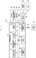
- FIG. 1 illustrates a network environment 100 including an electronic device 101 according to various embodiments of the present disclosure.
- the electronic device 101 may include various components including a bus 110, a processor 120, a memory 130, an input/output interface 140, a display 150, a communication interface 160, and a power management module 170.
- the bus 110 may be a circuit connecting the above described components and transmitting communication (e.g., a control message) between the above described components.
- the processor 120 may receive commands from other components (e.g., the memory 130, the input/output interface 140, the display 150, the communication interface 160, or the power management module 170) through the bus 110, analyze the received commands, and execute calculation or data processing according to the analyzed commands.
- other components e.g., the memory 130, the input/output interface 140, the display 150, the communication interface 160, or the power management module 170.
- the memory 130 stores commands or data received from the processor 120 or other components (e.g., the input/output interface 140, the display 150, the communication interface 160, or the power management module 170) or generated by the processor 120 or other components.
- the memory 130 may store a software and/or a program.
- the program may include a kernel 131, middleware 132, an Application Programming Interface (API) 133, and an application program (or an application) 134. At least part of the kernel 131, the middleware 132 or the API 133 may refer to an operating system (OS).
- OS operating system
- the kernel 131 controls or manages system resources (e.g., the bus 110, the processor 120, or the memory 130) used for executing an operation or function implemented by the remaining other programming modules, for example, the middleware 132, the API 133, or the application 134. Further, the kernel 131 provides an interface for accessing individual components of the electronic device 101 from the middleware 132, the API 133, or the application 134 to control or manage the components.
- system resources e.g., the bus 110, the processor 120, or the memory 130
- the kernel 131 provides an interface for accessing individual components of the electronic device 101 from the middleware 132, the API 133, or the application 134 to control or manage the components.
- the middleware 132 performs a relay function of allowing the API 133 or the application 134 to communicate with the kernel 131 to exchange data. Further, in operation requests received from the application 134, the middleware 132 performs a control for the operation requests (e.g., scheduling or load balancing) by using a method of assigning a priority, by which system resources (e.g., the bus 110, the processor 120, the memory 130 and the like) of the electronic device 101 can be used, to the application 134.
- system resources e.g., the bus 110, the processor 120, the memory 130 and the like
- the API 133 is an interface by which the application 134 can control a function provided by the kernel 131 or the middleware 132 and includes, for example, at least one interface or function (e.g., command) for a file control, a window control, image processing, or a character control.
- a function provided by the kernel 131 or the middleware 132 and includes, for example, at least one interface or function (e.g., command) for a file control, a window control, image processing, or a character control.
- the application 134 may include a Short Message Service (SMS)/Multimedia Messaging Service (MMS) application, an email application, a calendar application, an alarm application, a health care application (e.g., application measuring quantity of exercise or blood sugar) or an environment information application (e.g., application providing information on barometric pressure, humidity or temperature). Additionally, or alternatively, the application 134 may be an application related to an information exchange between the electronic device 101 and an external electronic device (e.g., electronic device 104). The application 134 related to the information exchange may include, for example, a notification relay application for transferring particular information to the external electronic device or a device management application for managing the external electronic device.
- SMS Short Message Service
- MMS Multimedia Messaging Service
- MMS Multimedia Messaging Service
- an email application e.g., email application, a calendar application, an alarm application, a health care application (e.g., application measuring quantity of exercise or blood sugar) or an environment information application (e.g., application providing information on barometric
- the notification relay application may include a function of transmitting notification information generated by another application (e.g., an SMS/MMS application, an email application, a health care application or an environment information application) of the electronic device 101 to the external electronic device (e.g., electronic device 104). Additionally, or alternatively, the notification relay application may receive notification information from, for example, the external electronic device 104, and provide the received notification information to the user.
- the device management application may manage (e.g., install, remove, or update) at least a part of functions of the electronic device.
- the device management application may turn on/off the external electronic device (or some components of the external electronic device), control a brightness of the display of the external electronic device or communicate with the electronic device 101, an application executed in the external electronic device 104, or a service (e.g., call service or message service) provided by the external electronic device 104.
- a service e.g., call service or message service
- the application 134 may include an application designated according to an attribute (e.g., type of electronic device) of the external electronic device 104.
- an attribute e.g., type of electronic device
- the application 134 may include an application related to music reproduction.
- the application 134 may include an application related to health care.
- the application 134 may include at least one of an application designated to the electronic device 101 and an application received from an external electronic device (e.g., server 106 or electronic device 104).
- the input/output interface 140 transmits a command or data input from the user through an input/output device 140 (e.g., a sensor, a keyboard, or a touch screen) to the processor 120, the memory 130, the communication interface 160, or the display control module 150 through, for example, the bus 110.
- the input/output interface 140 may provide data on a user's touch input through a touch screen to the processor 120.
- the input/output interface 140 may output a command or data received, through, for example, the bus 110, from the processor 120, the memory 130, the communication interface 160, or the power management module 170 through the input/output device (e.g., a speaker or a display).
- the input/output interface 140 may output voice data processed through the processor 120 to the user through the speaker.
- the display 150 may include, for example, liquid crystal display (LCD), flexible display, transparent display, light-emitting diode(LED) display, organic light-emitting diode (OLED) display, microelectromechanical systems (MEMS) display, or electronic paper display.
- the display 150 may visually offer, for example, various contents (e.g., text, image, video, icon, symbol, etc.) to users.
- the display 150 may include a touch screen and receive, for example, a touch, gesture, proximity, or hovering input using an electronic pen or a user's body.
- the display 150 may be one or more displays.
- the display 150 may be included in the electronic device 101 or included in an external device (e.g., the electronic device 102 or 104) having a wired or wireless connection with the electronic device 101, thus outputting information offered by the electronic device 101 to users.
- the display 150 may be attachable to or detachable from the electronic device 101.
- the display 150 may include an interface which can be mechanically or physically connected with the electronic device 101.
- the display 150 in case the display 150 is detached (e.g., separated) from the electronic device 101 by a user's selection, the display 150 may receive various control signals or image data from the power management module 170 or the processor 120, e.g., through wireless communication.
- the communication interface 160 may establish communication between the electronic device 101 and any external device (e.g., the first external electronic device 102, the second external electronic device 104, or the server 106).
- the communication interface 160 may be connected with a network 162 through wired or wireless communication and thereby communicate with any external device (e.g., the first external electronic device 102, the second external electronic device 104, or the server 106).
- the electronic device 101 may be connected with the first external electronic device 102 and the second external electronic device 104 without using the communication interface 160. For example, based on at least one of a magnetic sensor, a contact sensor, a light sensor, and the like that is equipped in the electronic device 101, the electronic device 101 may sense whether at least one of the first and second external electronic devices 102 and 104 is contacted with at least part of the electronic device 101, or whether at least one of the first and second external electronic device 102 and 104, respectively, is attached to at least part of the electronic device 101.
- Wireless communication may use, as cellular communication protocol, at least one of LTE (long-term evolution), LTE-A (LTE Advance), CDMA (code division multiple access), WCDMA (wideband CDMA), UMTS (universal mobile telecommunications system), WiBro (Wireless Broadband), GSM (Global System for Mobile Communications), and the like, for example.
- a short-range communication 163 may include, for example, at least one of Wi-Fi, Bluetooth, Near Field Communication (NFC), Magnetic Secure Transmission or near field Magnetic data Stripe Transmission (MST), and Global Navigation Satellite System (GNSS), and the like.
- the GNSS may include at least one of, for example, a Global Positioning System (GPS), a Global navigation satellite system (Glonass), a Beidou Navigation Satellite System (hereinafter, referred to as "Beidou”), and Galileo (European global satellite-based navigation system).
- GPS Global Positioning System
- Beidou Beidou Navigation Satellite System
- Galileo European global satellite-based navigation system
- Wired communication may include, for example, at least one of USB (universal serial bus), HDMI (high definition multimedia interface), RS-232 (recommended standard-232), POTS (plain old telephone service), and the like.
- the network 162 may include telecommunication network, for example, at least one of a computer network (e.g., LAN or WAN), internet, and a telephone network.
- the first and second external electronic devices 102 and 104 may be identical to, or different from, the electronic device 101.
- the first and second external electronic devices 102 and 104 may include, for example, a plurality of electronic devices.
- the server 106 may include a single server or a group of servers. According to various embodiments, all or part of operations executed in the electronic device 101 may be executed in other electronic device(s), such as the first and second electronic devices 102 and 104 or the server 106.
- the electronic device 101 may request another device (e.g., the electronic device 102 or 104 or the server 106) to execute instead, or additionally at least part, of at least one or more functions associated with the required function or service.
- the requested device may execute the requested function and deliver the result of execution to the electronic device 101.
- the electronic device 101 may offer the required function or service, based on the received result or by processing the received result.
- cloud computing technology distributed computing technology, or client-server computing technology may be used, for example.
- the camera module 170 is a device capable of obtaining still images and moving images.
- the camera module 170 may include at least one image sensor (e.g., a front sensor or a rear sensor), a lens, an ISP (Image Signal Processor), or a flash (e.g., LED, xenon lamp, etc.).
- image sensor e.g., a front sensor or a rear sensor
- lens e.g., a lens
- ISP Image Signal Processor
- flash e.g., LED, xenon lamp, etc.
- the power management module 180 may manage electric power of the electronic device 101.
- the power management module 180 may include a PMIC (Power Management Integrated Circuit), a charger IC (Integrated Circuit), or a battery or fuel gauge.
- the power management module 180 e.g., the PMIC
- the power management module 180 may supply electric power of the battery to other elements (e.g., the processor 120).
- the power management module 180 may receive a command from the processor 120 and manage the supply of power in response to the command.
- the power management module 180 may supply electric power to the display 140, the camera module 170, and the like.
- the PMIC may have a wired and/or wireless charging type.
- the wireless charging type may include, for example, a magnetic resonance type, a magnetic induction type, or an electromagnetic type.
- An additional circuit for wireless charging may be further used such as a coil loop, a resonance circuit, or a rectifier.
- the battery gauge may measure the residual amount of the battery and a voltage, current or temperature in a charging process.
- the battery may include, for example, a rechargeable battery and/or a solar battery.
- FIG. 2 is a block diagram illustrating a configuration of an electronic device 200 (e.g., electronic device 101) according to various embodiments.
- the electronic device 200 may include an image sensor 201, buffer 202, scaler 203, conversion module 204, and synthesis module 205.
- the image sensor 201 can receive electric power from a power management module 180 and generate image data using the electric power.
- the image sensor 201 can generate the image data in a Bayer pattern method and the generated image data may be referred to as Bayer data.
- the image sensor 201 can process the Bayer data to RGB data (e.g., generating RGB data by performing an interpolation operation for the Bayer data) and transmit the RGB data to the buffer 202.
- RGB data e.g., generating RGB data by performing an interpolation operation for the Bayer data
- Each pixel of the RGB data may have an R (red) value, G (green) value, and B (blue) value.
- the scaler 203 can perform a function of reducing the size of the RGB data.
- the scaler 203 can receive a plurality of RGB data items from the buffer 202, reduce the number of pixels (components of each of RGB data items) from 20 mega to 2 mega and transmit the reduced RGB data items to an ISP 204.
- Such a function of the scaler 203 may be performed by an image signal processor (ISP).
- ISP image signal processor
- the conversion module 204 can change a color expression of image data from RGB to YUV.
- the conversion module 204 can receive a plurality of scaled down RGB data items from the scaler 203, generate YUV data by changing the color expression of each received RGB data item from RGB to YUV, and transmit the YUV data to the synthesis module 205.
- the conversion module 204 can receive a plurality of RGB data items from the buffer 202, generate YUV data by changing the color expression of each received RGB data item from RGB to YUV, and transmit the YUV data to the synthesis module 205.
- first YUV data namely, data scaled down and converted from RGB to YUV
- second YUV data namely, data converted from RGB to YUV without scaling down
- the function of conversion module 204 may be performed by an ISP.
- the synthesis module 205 can receive a plurality of first YUV data items from the conversion module 204, generate display data by synthesizing the plurality of first YUV data items to one first YUV data item, and transmit the display data to a display. Subsequently, the synthesis module 205 can receive a plurality of second YUV data items from the conversion module 204, synthesize the plurality of received second YUV data items to one second YUV data item, generate storage data by encoding the synthesized second YUV data item, and transmit the storage data to a memory. Such a function of the synthesis module 205 may be performed by an application processor (AP) (e.g., processor 120).
- AP application processor
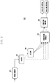
- FIG. 3 is a block diagram illustrating a configuration of an electronic device 300 (e.g., electronic device 101) according to various embodiments.
- the electronic device 300 may include an image sensor 301, buffer 302, scaler 303, first conversion module 304, second conversion module 305, first synthesis module 306, and second synthesis module 307.
- the image sensor 301 can receive electric power from a power management module 180 and generate Bayer data using the electric power. Further, the image sensor 301 can process the Bayer data to RGB data and transmit the Bayer data to the buffer 320.
- the scaler 303 can receive a plurality of RGB data items from the buffer 302, reduce the number of pixels (components of RGB data), and transmit the reduced RGB data to the first conversion module 304. Such a function of the scaler 303 may be performed by an ISP.
- the first conversion module 304 can receive RGB data from the scaler 303, generate first YUV data by changing a color expression of the RGB data to YUV, and transmit the first YUV data to the first synthesis module 306. Such a function of the first conversion module 304 may be performed by an ISP.
- the second conversion module 305 can receive RGB data from the buffer 302, generate second YUV data by converting a color expression of the RGB data to YUV, and transmit the second YUV data to the second synthesis module 307. Such a function of the second conversion module 305 may be performed by an ISP.
- the first synthesis module 306 can generate display data by synthesizing a plurality of first YUV data items to one first YUV data item, and transmit the display data to a display. Such a function of the first synthesis module 306 may be performed by an AP.
- the second synthesis module 307 can synthesize the plurality of received second YUV data items for one second YUV data item, generate storage data by encoding the synthesized second YUV data item, and transmit the storage data to a memory. Such a function of the second synthesis module 307 may be performed by an AP.
- An electronic device may include an image sensor, a display configured to acquire a user input, and a processor functionally connected to the image sensor and the display.
- the processor may be configured to, if the user input has a first input time, display image information acquired from the image sensor through the display, and, if the user input has a second input time, perform an operation of storing the image information.
- the processor may be configured to identify an attribute of the user input acquired through the display and to perform a function corresponding to the identified attribute, and the identified attribute may include at least one of information indicating a direction, information indicating time, and information related to an object contacting or hovering over the display.
- the processor may be configured to identify an attribute of the user input acquired through the display and to control the image sensor based setting information corresponding to the identified attribute; and the identified attribute may include at least one of information indicating a direction, information indicating time, and information related to an object contacting or hovering over the display.
- the processor may be configured to drive the image sensor in response to a first user input acquired through the display and to terminate the driving of the image sensor if an attribute of a second user input acquired from the display satisfies a predetermined condition.
- the processor may be configured to terminate the driving of the image sensor if a direction of the second user input is opposite to a direction of the first user input.
- the processor may be further configured to, in response to a stop of a gesture on the display, transmit a first drive command to the image sensor, receive first data from the image sensor as a response to the first drive command, generate processing data by processing the first data, and control the display to display the processing data by converting the processing data to an image.
- the processor may be further configured to, in response to a release of the gesture, transmit a second drive command to the image sensor, receive second data from the image sensor as a response to the second drive command, generate first processing data and second processing data having a greater capacity than the first processing data by processing the second data, control the display to display the first processing data by converting the first processing data to an image, encode the second processing data, and store the encoded data.
- Generating the first processing data by the processor may comprise reducing the size of the received data and converting a color expression of the received data from RGB to YUV.
- Generating the second processing data by the processor may comprise a procedure of converting the color expression of the received data from RGB to YUV.
- the processor may be configured to transmit the first processing data or encoded data of the first processing data to an external device in response to the release of the gesture.
- the processor may be configured to control the flashlight to emit light at the time of transmitting the second drive command.
- An electronic device may include an image sensor, a display, an input device configured to acquire a user gesture, and a processor functionally connected to the image sensor and the display.
- the processor may be configured to, in response to a release of a gesture on the display, transmit a drive command to the image sensor, receive data from the image sensor as a response to the drive command, generate first processing data and second processing data having a greater capacity than the first processing data by processing the data, control the display to display the first processing data by conversion to an image, encode the second processing data, and store the encoded data.
- Generating the first processing data by the processor may comprise reducing the size of the received data and converting a color expression of the received data from RGB to YUV, and generating the second processing data by the processor may comprise converting the color expression of the received data from RGB to YUV.
- the input device may include a key formed in at least one part of a touch panel installed in the display or in an area physically separated from the display.
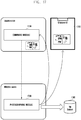
- An electronic device may include an input device configured to acquire a user gesture; an image sensor configured to generate data in response to light; a display configured to display an image corresponding to the data; a communication module configured to communicate with an external device; and a processor configured to control the image sensor, the display, and the communication module in response to the gesture received from the input device.
- the processor may be configured to control the display to display a user interface screen in order to transmit a message to and receive a message from an external device, in response to a release of a gesture received from the input device while displaying the user interface screen; to transmit a drive command to the image sensor; to receive data from the image sensor in response to the drive command; to generate processing data by processing the data; and to transmit the processing data or encoded data of the processing data to the external device through the communication module.
- An electronic device may include an image sensor, a display configured to acquire a user input, and a processor functionally connected to the image sensor and the display.
- the processor can be configured so that the image sensor operates in a first mode if the user input has a first attribute, and the image sensor operates in a second mode if the user input has a second attribute.
- the processor can control the image sensor to perform a first function in the first mode and a second function in the second mode.
- the first function may be photographing a still image and the second function may be photographing a moving image.
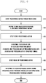
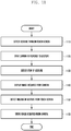
- Figure 4 illustrates a photographing method according to an embodiment.
- the photographing method can be performed when a display of an electronic device 101 is in a switched-off state (e.g., when a display is an inactive state because a power supply from a power management module 180 is blocked), or when a predetermined screen (e.g., lock screen, home screen) or an execution screen of a specific application (e.g., instant message (IM) application) is displayed in a display.
- a switched-off state e.g., when a display is an inactive state because a power supply from a power management module 180 is blocked
- a predetermined screen e.g., lock screen, home screen
- an execution screen of a specific application e.g., instant message (IM) application
- the processor 120 may detect a predetermined gesture through a touch screen (e.g., display 150).
- a touch screen e.g., display 150
- the processor 120 may detect a release of the predetermined gesture.
- the release may mean a release of contact between an object (e.g., finger or pen) and a touch screen or a release of a hovering object.
- the processor 120 can identify the release of the predetermined gesture as a photographing command.
- the electronic device 101 e.g., electronic device 200 or electronic device 300
- the electronic device 101 can perform the following operation 430.
- the image sensor is driven. For example, if a photographing command is generated by a user, the processor 120 can transmit a command for supplying power to a power management module 180, and the power management module 180 can supply electric power to the image sensor in response to reception of the command. Further, the processor 120 can transmit a drive command (capture command) to the image sensor, and the image sensor can generate data and transmit the data to the processor 120 in response to reception of the drive command. Further, if the display 150 is in a switched-off state, the processor 120 can control the power management module 180 to supply power to the display 150, and the power management module 180 can supply an electric power to the display 150.
- the processor 120 can receive data (e.g., RGB data) from the image sensor.
- the processor 120 can generate first processing data (e.g., first YUV data) and second processing data (e.g., second YUV data) having a greater capacity than the first processing data by processing the data.
- first processing data e.g., first YUV data
- second processing data e.g., second YUV data
- the processor 120 can transmit the first processing data as display data to the display 150. Accordingly, the display 150 can display the display data in a screen by converting the display data to an image. Further, the processor 120 can encode the second processing data and store the encoded data in the memory 130.
- the processor 120 can guide a user to a photographing timing. For example, if a photographing command is generated by the user, the processor 120 can wake up from a sleep state. The woken up processor 120 can control to supply power to the display 150 and the image sensor of the camera module 170. Further, the processor 120 can load setting information in an internal memory of the camera module 170. Subsequently, the processor 120 can command the image sensor to drive and simultaneously command a flashlight to emit light. Alternatively, the processor 120 can control the flashlight to emit light in response to receiving data (e.g., RGB data) from the image sensor as a response to the drive command.
- data e.g., RGB data
- the processor 120 can encode the image data (e.g., first YUV data) and transmit the encoded data to an external device (e.g., electronic device 102, electronic device 104, or server 106) through the communication interface 160.
- an external device e.g., electronic device 102, electronic device 104, or server 106
- the processor 120 can control the communication interface 160 to transmit the encoded data to an electronic device of an interlocutor of the user.
- the counterpart device can display the encoded data in a screen by decoding the encoded data.
- Figure 5 illustrates a photographing method according to another embodiment.
- the photographing method can be performed when a display 150 of an electronic device 101 is in a switched-off state or a predetermined screen is displayed in the display 150.
- the processor 120 may detect a predetermined gesture through a touch screen (e.g., display 150).
- a touch screen e.g., display 150
- the processor 120 may prepare to drive an image sensor (e.g., image sensor 201 or image sensor 301) in response to the detection of the predetermined gesture. For example, if the predetermined gesture is detected, the processor 120 can command a power management module 180 to supply electric power to the image sensor. Accordingly, the power management module 180 can supply the electric power to the image sensor. Further, the processor 120 can transmit camera setting information (e.g., AE (Auto Exposure), AWB (Auto White Balance), AF (Auto Focus), ISO (International Organization for Standardization) sensitivity, shutter speed, aperture value, and zoom magnification) stored in a memory 130 to an internal memory of a camera module 150. An operation of the camera module 150 (e.g., operation of generating data of image sensor) can be performed based on the setting information stored in the internal memory.
- camera setting information e.g., AE (Auto Exposure), AWB (Auto White Balance), AF (Auto Focus), ISO (International Organization for Standardization) sensitivity, shutter speed, aperture value, and zoom magnification
- the processor 120 may detect a stop of the predetermined gesture.
- the stop may mean a stop of an object (e.g., finger or pen) moving in a state of contacting (or hovering over) a touch screen.
- the processor 120 can identify the stop as a preview command.
- the electronic device 101 can perform the following operation 540 in response to the preview command.
- the processor 120 can transmit a drive command to the image sensor and receive image data (e.g., RGB data) from the image sensor as a response to the drive command. Further, if the display 150 is in a switched-off state, the processor 120 can command the power management module 180 to supply power to the display 150, and the power management module 180 can supply power to the display 150 accordingly.
- image data e.g., RGB data
- the processor 120 can generate processing data (e.g., first YUV data) by processing the received data.
- processing data e.g., first YUV data
- the processor 120 can transmit the processing data as display data to the display 150. Accordingly, the display 150 can convert the display data to a preview image and display the preview image.
- the processor 120 may detect a release of the predetermined gesture.
- the release may mean a release of contact between an object (e.g., finger or pen) and a touch screen, or a release of a hovering object.
- the processor 120 can identify the release of the predetermined gesture as a photographing command.
- the electronic device 101 can perform the following operation 560 in response to the photographing command.
- the processor 120 can transmit a drive command to the image sensor and receive image data (e.g., RGB data) from the image sensor as a response to the drive command.
- image data e.g., RGB data
- the processor 120 can generate first processing data (e.g., first YUV data) and second processing data (e.g., second YUV data) having a greater capacity than the first processing data by processing the data received from the image sensor.
- first processing data e.g., first YUV data
- second processing data e.g., second YUV data
- the processor 120 can transmit the first processing data as display data to the display 150. Accordingly, the display 150 can convert the display data to an image and display the image. Further, the processor 120 can encode the second processing data and store the encoded data in the memory 130.
- the processor 120 can guide a user to a photographing timing.
- the processor 120 can command the image sensor to drive and simultaneously command a flashlight to emit light.
- the processor 120 can control the flashlight to emit light in response to receiving data (e.g., RGB data) from the image sensor as a response to the drive command.
- data e.g., RGB data
- the processor 120 can encode image data (e.g., first YUV data) and transmit the encoded data to an external device (e.g., electronic device 102, electronic device 104, or server 106) through a communication interface 160.
- image data e.g., first YUV data
- an external device e.g., electronic device 102, electronic device 104, or server 106
- Figure 6 illustrates a photographing method according to another embodiment.
- the photographing method can be performed when a display 150 of an electronic device 101 is in a switched-off state or a predetermined screen is displayed in the display 150.
- the processor 120 may detect a predetermined gesture through a touch screen (e.g., display 150).
- a touch screen e.g., display 150
- the processor 120 may prepare to drive an image sensor in response to the detection of the predetermined gesture. For example, if the predetermined gesture is detected, the processor 120 can command a power management module 180 to supply electric power to the image sensor. Accordingly, the power management module 180 can supply the electric power to the image sensor.
- the processor 120 may detect a stop of the predetermined gesture.
- the stop may mean a stop of an object (e.g., finger or pen) moving in a state of contacting (or hovering over) a touch screen.
- the processor 120 can identify the stop as a preview command.
- the electronic device 101 can perform the following operation 640 in response to the preview command.
- the processor 120 can transmit a drive command to the image sensor and receive image data (e.g., RGB data) from the image sensor as a response to the drive command. Further, if the display 150 is in a switched-off state, the processor 120 can command the power management module 180 to supply power to the display 150, and the power management module 180 can supply power to the display 150 accordingly.
- image data e.g., RGB data
- the processor 120 can generate first processing data (e.g., first YUV data) by processing the data received from the image sensor.
- first processing data e.g., first YUV data
- the processor 120 can transmit the first processing data as display data to the display 150. Accordingly, the display 150 can convert the display data to an image and display the image.
- the processor 120 can guide a user to a photographing timing.
- the processor 120 can command the image sensor to drive and command a flashlight to emit light at the same time.
- the processor 120 can control the flashlight to emit light in response to receiving data from the image sensor as a response to the drive command.
- the processor 120 may detect a release of the predetermined gesture.
- the release may mean a release of contact between an object (e.g., finger or pen) and a touch screen or a release of a hovering object.
- the processor 120 can identify the release of the predetermined gesture as a storage command.
- the processor 120 can generate second processing data (e.g., second YUV data) by processing data received from the image and store encoded data in a memory 130 in response to the storage command.
- second processing data e.g., second YUV data
- the processor 120 can identify the release of the predetermined gesture as a transmission command.
- the processor 120 can encode the image data (e.g., first YUV data) and transmit the encoded data to an external device (e.g., electronic device 102, electronic device 104, or server 106) through a communication interface 160.
- the processor 120 can transmit the image data to the external device without encoding the image data.
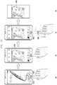
- Figure 7 illustrates a user interface screen of an electronic device for performing a photographing method according to various embodiments.
- an electronic device e.g., smartphone
- the electronic device can determine whether the identified gesture is a photographing command. For example, if the identified gesture is an operation that three fingers 710 are released after moving in a predetermined direction (e.g., from top to bottom) in a state of contacting or hovering over a touch screen, the electronic device can determine that a photographing command is generated.
- the electronic device can acquire image data 720 (e.g., RGB data) from a camera in response to a photographing command.
- image data 720 e.g., RGB data
- the electronic device can display an image 730 corresponding to the image data 720 in a touch screen.
- the electronic device can generate first YUV data by resizing RGB data and changing a color expression from RGB to YUV.
- the electronic device can synthesize a plurality of first YUV data items for one YUV data item, convert the synthesized data to an image 730, and display the image 730 in the touch screen.
- the electronic device can generate second YUV data by changing a color expression of the image data 720 from RGB to YUV in order to increase an encoding efficiency.
- the electronic device can synthesize a plurality of second YUV data items for one YUV data item and store the synthesized data in a memory by encoding.
- the processor 120 can encode image data (e.g., first YUV data) and transmit the encoded data to an external device (e.g., electronic device 102, electronic device 104, or server 106) through a communication interface 160.
- image data e.g., first YUV data
- an external device e.g., electronic device 102, electronic device 104, or server 106
- Figure 8 illustrates a user interface screen of an electronic device for performing a photographing method according to various embodiments.
- an electronic device e.g., smartphone
- the electronic device can determine whether the identified gesture is a preview command. For example, if the identified gesture is an operation that three fingers 710 are released after moving in a predetermined direction (e.g., from top to bottom) in a state of contacting or hovering over a touch screen, the electronic device can determine that a preview command is generated.
- the electronic device can acquire image data (e.g., RGB data) from a camera and display an image 820 corresponding to the image data in a touch screen in response to the preview command.
- image data e.g., RGB data
- a user may release three fingers 810 from the touch screen while the image 820 is being displayed.
- the electronic device can store image data 830 in a memory by processing the image data in response to the release of the fingers.
- the electronic device can generate YUV data by changing a color expression of the image data from RGB to YUV.
- the electronic device can synthesize a plurality of YUV data items for one YUV data item and store the synthesized data in a memory.
- the processor 120 can encode image data (e.g., first YUV data) and transmit the encoded data to an external device (e.g., electronic device 102, electronic device 104, or server 106) through a communication interface 160.
- image data e.g., first YUV data
- an external device e.g., electronic device 102, electronic device 104, or server 106
- Figure 9 illustrates a user interface screen of an electronic device for performing a photographing method according to various embodiments.
- the electronic device e.g., smartphone
- the electronic device can identify a gesture of an object through a key formed in an area physically separated from a touch screen (e.g., touch key 910 formed under the touch screen) or from a partial area of the touch screen (e.g., part adjacent to the touch key 910).
- the electronic device can determine whether the identified gesture is a photographing command. For example, if the identified gesture is an operation that a finger 920 touched the touch key two times and then was taken off, the electronic device can determine that a photographing command is generated.
- the electronic device can acquire image data 930 shown in Figure 9(b) from a camera and display an image 940 (refer to Figure 9(c) ) corresponding to the image data 930 in the touch screen.
- the processor 120 can encode the image data (e.g., YUV data) and transmit the encoded data to an external device (e.g., electronic device 102, electronic device 104, or server 106) through a communication interface 160.
- Figure 10 illustrates a user interface screen of an electronic device for performing a photographing method according to various embodiments.
- the electronic device e.g., smartphone
- the electronic device can identify a gesture of an object through a key formed in an area physically separated from a touch screen (e.g., touch key 1010 formed under the touch screen) or from a partial area of the touch screen (e.g., part adjacent to the touch key 1010).
- the electronic device can determine whether the identified gesture is a preview command. For example, if the identified gesture is an operation that a finger 1020 touches the touch key 1010 two times, is taken off, and touches again, the electronic device can determine that a preview command is generated.
- the electronic device in response to the preview command, can acquire image data (e.g., RGB data) from a camera and display a corresponding image 1030 in the touch screen.
- image data e.g., RGB data
- the user can release the finger 1020 from the touch key 1010 while the image 1030 is being displayed.
- the electronic device can process and store image data 1040 in a memory in response to the release of the finger. Additionally or as an alternative of the storage operation, the processor 120 can encode the image data (e.g., YUV data) and transmit the encoded data to an external device (e.g., electronic device 102, electronic device 104, or server 106) through a communication interface 160.
- image data e.g., YUV data
- an external device e.g., electronic device 102, electronic device 104, or server 106
- Figure 11 illustrates a photographing method according to another embodiment.
- the photographing method can be performed when a display 150 of an electronic device 101 is in a switched-off state or a predetermined screen is displayed in the display 150.
- the processor 120 may detect a gesture through a touch screen (e.g., display 150).
- a touch screen e.g., display 150
- the processor 120 may drive a camera in response to the gesture. For example, if the gesture is detected, the processor 120 can command a power management module 180 to supply electric power to a camera module 170. Accordingly, the power management module 180 can supply the electric power to the camera module 170, and the camera module 170 can generate image data and transmit the image data to the processor 120.
- the processor 120 may detect a stop of the gesture from the touch screen.
- the processor 120 may control the display 150 to display an image acquired from the camera in response to the stop of the gesture.
- the processor 120 can process the image data received from the camera module 170 to display data and transmit the display data to the display 150.
- the processor 120 may detect a release of a gesture from the touch screen.
- the processor 120 stores the image acquired from the camera in a memory 130 in response to the release of the gesture.
- the processor 120 can encode the image data received from the camera module 170 and transmit the encoded data to the memory 130.
- Figure 12 illustrates a method for operating a camera according to an embodiment.
- the processor 120 may detect a first gesture through a touch screen (e.g., display 150).
- a touch screen e.g., display 150
- the processor 120 may drive a camera in response to the first gesture.
- the processor 120 may detect a second gesture from the touch screen.
- an object e.g., finger or pen
- the continuance of the object may be identified as a second gesture.
- the processor 120 can detect a new gesture from the touch screen. Namely, the new gesture may be identified as the second gesture.
- the processor 120 may perform a camera function corresponding to the second gesture.
- the processor 120 can control a display 150 to display an image acquired from the camera. Additionally or alternatively, the processor 120 can store the image acquired from the camera in a memory 130.
- camera functions to be performed may vary depending on an attribute of the second gesture.
- the processor 120 can receive information indicating a second gesture from the touch screen and identify the attribute of the second gesture by processing the information.
- the identified attribute may include information indicating a direction, information indicating time, or information of a corresponding object.
- the attribute may include a direction of an object moving on a touch screen, contacting or hovering time of an object on a touch screen, distance (depth) between an object and a touch screen, number of objects contacting or hovering over a touch screen, type of object contacting or hovering over a touch screen (e.g., finger or pen), and hand in use (namely, information indicating with which hand a user performs a gesture).
- the processor 120 can search a function corresponding to the identified attribute from a lookup table stored in the memory 130 and perform the identified camera function (e.g., still shot, moving image shot, or change of photographing mode).
- the operation 1240 may be replaced by another operation.
- the processor 120 can stop the camera drive (e.g., image capture).
- the first gesture may be an operation that the user moved an object in a lower direction on the touch screen
- the second gesture may be an operation that the user moved the object in an upper direction.
- Figure 13 illustrates a method for operating a camera according to another embodiment.
- the processor 120 may detect a first gesture through a touch screen (e.g., display 150).
- a touch screen e.g., display 150
- the processor 120 may prepare to drive a camera in response to the first gesture. For example, if the first gesture is detected, the processor 120 can command a power management module 180 to supply electric power to an image sensor of the camera. Accordingly, the power management module 180 can supply electric power to the image sensor.
- the processor 120 may detect a second gesture through the touch screen.
- the processor 120 may control the camera based on setting information corresponding to the second gesture.
- the camera setting information e.g., AE (Auto Exposure), AWB (Auto White Balance), AF (Auto Focus), and ISO (International Organization for Standardization) sensitivity, shutter speed, aperture value, and zoom magnification
- the processor 120 can search setting information corresponding to the identified attribute from a lookup table stored in the memory 130 and transmit the identified setting information to the camera (e.g., internal memory (volatile memory) of camera). Accordingly, the camera can acquire the setting information by accessing to the internal memory and perform an operation of generating an image with the image sensor based on the setting information.
- the camera setting condition may vary according to a moving direction, moving distance, and trace type of the object.
- the moving direction of the second gesture changes from a lower side to a right side
- an exposure may increase proportionally to a movement distance from a change point.
- the moving direction of the second gesture changes from a lower side to a left side
- an exposure may decrease proportionally to a movement distance from a change point second gesture.
- the shutter speed may increase; and in the case of a counter-clockwise direction, the shutter speed may decrease.
- Figure 14 illustrates a method for operating a camera according to another embodiment.
- the processor 120 may detect a gesture through a touch screen (e.g., display 150).
- a camera e.g., camera module 170
- the camera can be driven before the detection of a gesture, and the display 150 may be in a switched-off state or in a state of displaying a predetermined screen (e.g., home screen or lock screen).
- the processor 120 may displays an image acquired from the camera if the gesture is maintained on the touch screen for more than a predetermined time (e.g., time count starts after a stop of a gesture, and if the time count exceeds a predetermined time without a release of the gesture), and stores the image acquired from the camera if the gesture is released from the touch screen within the predetermined time.
- a predetermined time e.g., time count starts after a stop of a gesture, and if the time count exceeds a predetermined time without a release of the gesture
- the processor 120 can process image data received from the camera module 170 to display data and transmit the display data to the display 150. If the gesture is released from the touch screen within the predetermined time, the processor 120 can encode the image data received from the camera module 170 and transmit the encoded data to a memory 130.
- a method for operating an electronic device may include the operations of acquiring a user input through a display; and, in response to acquiring the user input, displaying image information acquired through an image sensor through the display if the user input has a first input time, and storing the image information if the user input has a second input time.
- the method may further include an operation of identifying an attribute of a user input acquired through the display and an operation of performing a function corresponding to the identified attribute.
- the identified attribute may include at least one of information indicating a direction, information indicating time, and information related to an object contacting or hovering over the display.
- the method may further include an operation of identifying an attribute of a user input acquired through the display and an operation of controlling the image sensor based on setting information corresponding to the identified attribute.
- the identified attribute may include at least one of information indicating a direction, information indicating time, and information related to an object contacting or hovering over the display.
- the method may further include an operation of driving the image sensor in response to a first user input acquired through the display and an operation of terminating the drive of the image sensor if an attribute of a second user input acquired through the display satisfies a predetermined condition.
- the operation of terminating the drive may include an operation of terminating the drive of the image sensor if a direction of the second user input is opposite to a direction of the first user input.
- the operation of displaying may include the operations of transmitting a first drive command to the image sensor in response to a stop of a gesture on the display, receiving first data from the image sensor in response to the first drive command, generating processing data by processing the first data, converting the processing data to an image, and displaying the image.
- the operation of storing may include the operations of transmitting a second drive command to the images sensor in response to a release of a gesture, receiving second data from the image sensor in response to the second drive command, generating first processing data and second processing data having a greater capacity than the first processing data by processing the second data, converting the first processing data to an image, displaying the image, , encoding the second processing data, and storing the encoded data.
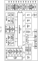
- FIG. 15 is a detailed block diagram showing a configuration of an electronic device 1501 according to various embodiments.
- the electronic device 1501 is capable of including part or all of the components in the electronic device 101 shown in FIG. 1 .
- the electronic device 1501 is capable of including one or more processors 1510 (e.g., Application Processors (APs)), a communication module 1520, a Subscriber Identification Module (SIM) 1524, a memory 1530, a sensor module 1540, an input device 1550, a display 1560, an interface 1570, an audio module 1580, a camera module 1591, a power management module 1595, a battery 1596, an indicator 1597, and a motor 1598.
- processors 1510 e.g., Application Processors (APs)
- APs Application Processors
- SIM Subscriber Identification Module
- the processor 1510 is capable of driving, for example, an operating system or an application program to control a plurality of hardware or software components connected to the processor 1510, processing various data, and performing operations.
- the processor 1510 may be implemented as, for example, a System on Chip (SoC).
- SoC System on Chip
- the processor 1510 may further include a graphic processing unit (GPU) and/or an image signal processor.
- the processor 1510 may also include at least part of the components shown in FIG. 15 , e.g., a cellular module 1521.
- the processor 1510 is capable of loading commands or data received from at least one of other components (e.g., a non-volatile memory) on a volatile memory, processing the loaded commands or data.
- the processor 1510 is capable of storing various data in a non-volatile memory.
- the communication module 1520 may include the same or similar configurations as the communication interface 160 shown in FIG. 1 .
- the communication module 1520 is capable of including a cellular module 1521, WiFi module 1523, Bluetooth (BT) module 1525, GNSS module 1526 (e.g., a GPS module, Glonass module, Beidou module or Galileo module), NFC module 1527, and Radio Frequency (RF) module 1529.
- a cellular module 1521 WiFi module 1523
- Bluetooth (BT) module 1525 e.g., a GPS module, Glonass module, Beidou module or Galileo module
- NFC module 1527 e.g., a GPS module, Glonass module, Beidou module or Galileo module
- RF Radio Frequency
- the cellular module 1521 is capable of providing a voice call, a video call, an SMS service, an Internet service, etc., through a communication network, for example.
- the cellular module 1521 is capable of identifying and authenticating an electronic device 1501 in a communication network by using a subscriber identification module (SIM) 1524 (e.g., a SIM card).
- SIM subscriber identification module
- the cellular module 1521 is capable of performing at least part of the functions provided by the processor 1510.
- the cellular module 1521 is also capable of including a communication processor (CP).
- CP communication processor
- Each of the WiFi module 1523, the BT module 1525, the GNSS module 1526, and the NFC module 1527 is capable of including a processor for processing data transmitted or received through the corresponding module.
- MST module is capable of including a processor for processing data transmitted or received through the corresponding module.
- at least part of the cellular module 1521, WiFi module 1523, BT module 1525, GNSS module 1526, NFC module 1527, and MST module (e.g., two or more modules) may be included in one integrated chip (IC) or one IC package.
- the RF module 1529 is capable of transmission/reception of communication signals, e.g., RF signals.
- the RF module 1529 is capable of including a transceiver, a power amp module (PAM), a frequency filter, a low noise amplifier (LNA), an antenna, etc.
- PAM power amp module
- LNA low noise amplifier
- at least one of the following modules: cellular module 1521, WiFi module 1523, BT module 1525, GNSS module 1526, NFC module 1527, and MST module is capable of transmission/reception of RF signals through a separate RF module.
- the SIM module 1524 is capable of including a card including a subscriber identification module (SIM) and/or an embodied SIM.
- SIM subscriber identification module
- the SIM module 1524 is also capable of containing unique identification information, e.g., integrated circuit card identifier (ICCID), or subscriber information, e.g., international mobile subscriber identity (IMSI).
- ICCID integrated circuit card identifier
- IMSI international mobile subscriber identity
- the memory 1530 (e.g., memory 130 shown in FIG. 1 ) is capable of including a built-in memory 1532 or an external memory 1534.
- the built-in memory 1532 is capable of including at least one of the following: a volatile memory, e.g., a dynamic RAM (DRAM), a static RAM (SRAM), a synchronous dynamic RAM (SDRAM), etc.; and a non-volatile memory, e.g., a one-time programmable ROM (OTPROM), a programmable ROM (PROM), an erasable and programmable ROM (EPROM), an electrically erasable and programmable ROM (EEPROM), a mask ROM, a flash ROM, a flash memory (e.g., a NAND flash memory, an NOR flash memory, etc.), a hard drive, a solid state drive (SSD), etc.
- a volatile memory e.g., a dynamic RAM (DRAM), a static RAM (SRAM),
- the external memory 1534 is also capable of including a flash drive, e.g., a compact flash (CF), a secure digital (SD), a micro secure digital (Micro-SD), a mini secure digital (Mini-SD), an extreme digital (xD), a multi-media card (MMC), a memory stick, etc.
- a flash drive e.g., a compact flash (CF), a secure digital (SD), a micro secure digital (Micro-SD), a mini secure digital (Mini-SD), an extreme digital (xD), a multi-media card (MMC), a memory stick, etc.
- the external memory 1534 is capable of being connected to the electronic device 1501, functionally and/or physically, through various interfaces.
- the memory 1530 is capable of storing payment information and a payment application serving as one of the application programs 154D.
- the payment information may refer to credit card numbers and PINs, corresponding to a credit card.
- the payment information may also include user authentication information, e.g., fingerprints, facial features, voice information, etc.
- the payment application When executed by the processor 1510, it may enable the processor 1510 to perform: an interaction with the user to make payment (e.g., displaying a screen to select a card (or a card image) and obtaining information (e.g., a card number) corresponding to a selected card (e.g., a pre-specified card) from payment information); and an operation to control magnetic field communication (e.g., transmitting the card information to an external device (e.g., a card reading apparatus) through the NFC module 1527 or MST module).
- an interaction with the user to make payment e.g., displaying a screen to select a card (or a card image) and obtaining information (e.g., a card number) corresponding to a selected card (e.g., a pre-specified card) from payment information
- an operation to control magnetic field communication e.g., transmitting the card information to an external device (e.g., a card reading apparatus) through the NFC module 1527
- the sensor module 1540 is capable of measuring/detecting a physical quantity or an operation state of the electronic device 1501, and converting the measured or detected information into an electronic signal.
- the sensor module 1540 is capable of including at least one of the following: a gesture sensor 1540A, a gyro sensor 1540B, an atmospheric pressure sensor 1540C, a magnetic sensor 1540D, an acceleration sensor 1540E, a grip sensor 1540F, a proximity sensor 1540G, a color sensor 1540H (e.g., a red, green and blue (RGB) sensor), a biometric sensor 15401, a temperature/humidity sensor 1540J, an illuminance sensor 1540K, and a ultraviolet (UV) sensor 1540M.
- a gesture sensor 1540A e.g., a gyro sensor 1540B
- an atmospheric pressure sensor 1540C e.g., a magnetic sensor 1540D
- an acceleration sensor 1540E e.g., a grip sensor 1540F
- the sensor module 1540 is capable of further including an E-nose sensor, an electromyography (EMG) sensor, an electroencephalogram (EEG) sensor, an electrocardiogram (ECG) sensor, an infrared (IR) sensor, an iris sensor and/or a fingerprint sensor.
- the sensor module 1540 is capable of further including a control circuit for controlling one or more sensors included therein.
- the electronic device 1501 is capable of including a processor, configured as part of the processor 1510 or a separate component, for controlling the sensor module 1540. In this case, while the processor 1510 is operating in sleep mode, the processor is capable of controlling the sensor module 1540.
- the input unit 1550 may include, for example, a touch panel 1552, a digital pen sensor 1554, a key 1556, or an ultrasonic input unit 1558.
- the touch panel 1552 may use, for example, at least one of a capacitive type, a resistive type, an infrared type, and an ultrasonic type.
- the touch panel 1552 may further include a control circuit.
- the touch panel 1552 may further include a tactile layer to offer a tactile feedback to a user.
- the touch panel 1552 may include a pressure sensor (or a force sensor) capable of measuring the strength or pressure of a user's touch. This pressure sensor may be formed integrally with or separately from the touch panel 1552.
- the digital pen sensor 1554 may be a part of the touch panel or include a separate sheet for recognition.
- the key 1556 may include, for example, a physical button, an optical key, or a keypad.
- the ultrasonic input unit 1558 may detect ultrasonic waves occurring at an input tool through a microphone (e.g., 1588) and thereby identify data corresponding to the detected ultrasonic waves.
- the display 1560 is capable of including a panel 1562, a hologram unit 1564, or a projector 1566.
- the panel 1562 may include the same or similar configurations as the display 150 shown in FIG. 1 .
- the panel 1562 may be implemented to be flexible, transparent, or wearable.
- the panel 1562 may also be incorporated into one module together with the touch panel 1552.
- the hologram unit 1564 is capable of showing a stereoscopic image in the air by using light interference.
- the projector 1566 is capable of displaying an image by projecting light onto a screen.
- the screen may be located inside or outside of the electronic device 1501.
- the display 1560 may further include a control circuit for controlling the panel 1562, the hologram unit 1564, or the projector 1566.
- the interface 1570 is capable of including a high-definition multimedia interface (HDMI) 1572, a universal serial bus (USB) 1574, an optical interface 1576, or a D-subminiature (D-sub) 1578.
- the interface 1570 may be included in the communication interface 160 shown in FIG. 1 .
- the interface 1570 is capable of including a mobile high-definition link (MHL) interface, a secure digital (SD) card/multimedia card (MMC) interface, or an infrared data association (IrDA) standard interface.
- MHL mobile high-definition link
- SD secure digital
- MMC multimedia card
- IrDA infrared data association
- the audio module 1580 is capable of providing bidirectional conversion between a sound and an electronic signal. At least part of the components in the audio module 1580 may be included in the input/output interface 140 shown in FIG. 1 .
- the audio module 1580 is capable of processing sound information input or output through a speaker 1582, a receiver 1584, earphones 1586, microphone 1588, etc.
- the camera module 1591 refers to a device capable of taking both still and moving images. According to an embodiment, the camera module 1591 is capable of including one or more image sensors (e.g., a front image sensor or a rear image sensor), a lens, an image signal processor (ISP), a flash (e.g., an LED or xenon lamp), etc.
- image sensors e.g., a front image sensor or a rear image sensor
- ISP image signal processor
- flash e.g., an LED or xenon lamp
- the power management module 1595 is capable of managing power of the electronic device 1501.
- the power management module 1595 is capable of including a power management integrated circuit (PMIC), a charger IC, or a battery or fuel gauge.
- PMIC power management integrated circuit
- the PMIC may employ wired charging and/or wireless charging methods. Examples of the wireless charging method are magnetic resonance charging, magnetic induction charging, and electromagnetic charging.
- the PIMC may further include an additional circuit for wireless charging, such as a coil loop, a resonance circuit, a rectifier, etc.
- the battery gauge is capable of measuring the residual capacity, charge in voltage, current, or temperature of the battery 1596.
- the battery 1596 takes the form of either a rechargeable battery or a solar battery.
- the indicator 1597 is capable of displaying a specific status of the electronic device 1501 or a part thereof (e.g., the processor 1510), e.g., a boot-up status, a message status, a charging status, etc.
- the motor 1598 is capable of converting an electrical signal into mechanical vibrations, such as, a vibration effect, a haptic effect, etc.
- the electronic device 1501 is capable of further including a processing unit (e.g., GPU) for supporting a mobile TV.
- the processing unit for supporting a mobile TV is capable of processing media data pursuant to standards, e.g., digital multimedia broadcasting (DMB), digital video broadcasting (DVB), or mediaFloTM, etc.
- DMB digital multimedia broadcasting
- DVD digital video broadcasting
- mediaFloTM mediaFloTM
- each of the elements described in the present disclosure may be formed with one or more components, and the names of the corresponding elements may vary according to the type of the electronic device.
- the electronic device may include at least one of the above described elements described in the present disclosure, and may exclude some of the elements or further include other additional elements. Further, some of the elements of the electronic device according to various embodiments may be coupled to form a single entity while performing the same functions as those of the corresponding elements before the coupling.
- FIG. 16 is a block diagram of a programming module according to various embodiments.
- the program module 1610 e.g., programs 131-134 shown in FIG. 1
- the program module 1610 is capable of including an operation system (OS) for controlling resources related to the electronic device (e.g., electronic device 101) and/or various applications (e.g., application programs 134 shown in FIG. 1 ) running on the OS.
- the OS may be Android, iOS, Windows, Symbian, Tizen, Bada, etc.
- the program module 1610 is capable of including a kernel 1620, middleware 1630, application programming interface (API) 1660 and/or applications 1670. At least part of the program module 1610 may be preloaded on the electronic device or downloaded from a server (e.g., an electronic device 102 or 104, server 106, etc.).
- a server e.g., an electronic device 102 or 104, server 106, etc.
- the kernel 1620 may include a system resource manager 1621 and/or a device driver 1623.
- the system resource manager 1621 may include, for example, a process manager, a memory manager, and a file system manager.
- the system resource manager 1621 may perform a system resource control, allocation, and recall.
- the device driver 1623 may include, for example, a display driver, a camera driver, a Bluetooth driver, a shared memory driver, a USB driver, a keypad driver, a WiFi driver, and an audio driver.
- the device driver 1612 may include an Inter-Process Communication (IPC) driver.
- IPC Inter-Process Communication
- the middleware 1630 may provide a function required in common by the applications 1670. Further, the middleware 1630 may provide a function through the API 1660 to allow the applications 1670 to efficiently use limited system resources within the electronic device.
- the middleware 1630 (for example, the middleware 14B) may include at least one of a runtime library 1635, an application manager 1641, a window manager 1642, a multimedia manager 1643, a resource manager 1644, a power manager 1645, a database manager 1646, a package manager 1647, a connection manager 1648, a notification manager 1649, a location manager 1650, a graphic manager 1651, and a security manager 1652.
- the runtime library 1635 may include, for example, a library module used by a complier to add a new function through a programming language while the applications 1670 are executed. According to an embodiment, the runtime library 1635 executes input and output, management of a memory, a function associated with an arithmetic function and the like.
- the application manager 1641 may manage, for example, a life cycle of at least one of the applications 1670.
- the window manager 1642 may manage GUI resources used on the screen.
- the multimedia manager 1643 may detect a format required for reproducing various media files and perform an encoding or a decoding of a media file by using a codec suitable for the corresponding format.
- the resource manager 1644 manages resources such as a source code, a memory, or a storage space of at least one of the applications 1670.
- the power manager 1645 may operate together with a Basic Input/Output System (BIOS) to manage a battery or power and provides power information required for the operation.
- BIOS Basic Input/Output System
- the database manager 1646 may manage generation, search, and change of a database to be used by at least one of the applications 1670.
- the package manager 1647 may manage an installation or an update of an application distributed in a form of a package file.
- the connection manager 1648 may manage, for example, a wireless connection such as WiFi or Bluetooth.
- the notification manager 1649 may display or notify a user of an event such as an arrival message, an appointment, a proximity alarm or the like, in a manner that does not disturb the user.
- the location manager 1650 may manage location information of the electronic device.
- the graphic manager 1651 may manage a graphic effect provided to the user or a user interface related to the graphic effect.
- the security manager 1652 provides a general security function required for a system security or a user authentication.
- the middleware 1630 may further include a telephony manager for managing a voice of the electronic device or a video call function.
- the middleware 1630 is capable of including modules configuring various combinations of functions of the above described components.
- the middleware 1630 is capable of providing modules specialized according to types of operation systems to provide distinct functions.
- the middleware 1630 may be adaptively configured in such a way as to remove part of the existing components or to include new components.
- the API 1660 may be a set of API programming functions, and may be provided with a different configuration according to an operating system. For example, in Android or iOS, a single API set may be provided for each platform. In Tizen, two or more API sets may be provided.
- the applications 1670 may include one or more applications for performing various functions, e.g., home 1671, diary 1672, SMS/MMS 1673, instant message (IM) 1674, browser 1675, camera 1676, alarm 1677, context 1678, voice dial 1679, email 1680, calendar 1681, media player 1682, album 1683, clock 1684, health care (e.g., an application for measuring amount of exercise, blood sugar level, etc.), and environment information (e.g., an application for providing atmospheric pressure, humidity, temperature, etc.).
- IM instant message
- the applications 1670 are capable of including an application for supporting information exchange between an electronic device (e.g., electronic device 161) and an external device (e.g., electronic devices 162 and 164), which is hereafter called 'information exchange application').
- the information exchange application is capable of including a notification relay application for relaying specific information to external devices or a device management application for managing external devices.
- the notification relay application is capable of including a function for relaying notification information, created in other applications of the electronic device (e.g., SMS/MMS application, email application, health care application, environment information application, etc.) to external devices (e.g., electronic devices 162 and 164).
- the notification relay application is capable of receiving notification information from external devices to provide the received information to the user.
- the device management application is capable of managing (e.g., installing, removing or updating) at least one function of an external device (e.g., electronic devices 162 and 164) communicating with the electronic device.
- an external device e.g., electronic devices 162 and 164
- Examples of the function are a function of turning-on/off the external device or part of the external device, a function of controlling the brightness (or resolution) of the display, applications running on the external device, services provided by the external device, etc.
- Examples of the services are a call service, messaging service, etc.
- the applications 1670 are capable of including an application (e.g., a health care application of a mobile medical device, etc.) specified attributes of an external device (e.g., electronic devices 102 and 104). According to an embodiment, the applications 1670 are capable of including applications received from an external device (e.g., a server 106, electronic devices 102 and 104). According to an embodiment, the applications 1670 are capable of including a preloaded application or third party applications that can be downloaded from a server. It should be understood that the components of the program module 1610 may be called different names according to types of operating systems.
- At least part of the program module 1610 can be implemented with software, firmware, hardware, or any combination of two or more of them. At least part of the program module 1610 can be implemented (e.g., executed) by a processor (e.g., processor 120). At least part of the programing module 1610 may include modules, programs, routines, sets of instructions or processes, etc., in order to perform one or more functions.
- Figure 17 is a block diagram illustrating a configuration of a program module 1700 according to various embodiments.
- the program module 1700 may include a command module 1710 and a photographing module 1720.
- the command module 1710 shown in Figure 17 may be a component of an application 1670.
- the command module 1710 may configure a part of a home 1671 or an IM (Instant Messenger) 1674.
- IM Instant Messenger
- the gesture can be transmitted to the IM 1674 through an operating system of the electronic device.
- the command module 1710 can identify the input gesture as a photographing command. Accordingly, the command module 1710 can control the photographing module 1720 to take a photo.
- the photographing module 1720 may be configured as a part of an application manager 1641 of a middleware 1630 shown in Figure 16 .
- the photographing module 1720 can perform the following functions.
- the photographing module 1720 can acquire image data (e.g., RGB data) from a camera.
- the photographing module 1720 can generate first YUV data by resizing the image data to a smaller size and changing a color expression from RGB to YUV.
- the photographing module 1720 can transmit the first YUV data to the IM 1674.
- the IM 1674 can perform a function of transmitting the first YUV data (or encoded data) to an external device in response to generation of a user transmission command (or without generation of the transmission command).
- the photographing module 1720 can store the first YUV data in a clipboard 1730.
- the application 1670 can use the first YUV data stored in the clipboard 1730.
- the IM 1674 may include the first YUV data stored in the clipboard 1730 in a send message.
- the photographing module 1720 can generate second YUV data by changing a color expression of the acquired image data from RGB to YUV, encode the second YUV data, and store the encoded data in a file system 1740.
- module used in the present invention means a unit including at least one of hardware, software, firmware, or their combinations.
- the “module” can be used interchangeably with the terms of a unit, logic, logical block, component, or circuit.
- the “module” can be configured in a mechanical form or an electronical form.
- the “module” according to the present invention may include at least one of an application-specific integrated circuit (ASIC) chip, field-programmable gate arrays (FPGAs), or programmable-logic device for executing certain operations, which are well known already or will be developed in future.
- ASIC application-specific integrated circuit
- FPGAs field-programmable gate arrays
- programmable-logic device for executing certain operations, which are well known already or will be developed in future.
- At least one part of the device e.g., modules or their functions
- method e.g., operations
- a command stored in computer-readable storage media in a program module form. If the command is executed by at least one processor, the processor can perform a function of the corresponding command.
- the computer-readable storage media may be a memory 130.
- At least one part of the programing module can be implemented by a processor. At least one part of the programing module may include a module, program, set of instructions, or process in order to perform at least one function.
- the computer-readable storage media may include a hard disk, floppy disk, magnetic media (e.g., magnetic tape), optical media (e.g., compact disc read only memory (CD-ROM) and digital versatile disc (DVD)), magneto-optical media (e.g., floptical disk), and hardware device (e.g., read only memory (ROM), random access memory (RAM), or flash memory).
- the command may include a high level language code executable by a computer using an interpreter as well as a machine language code created by a compiler.
- the hardware device can be configured with at least one software module to perform operations according to various embodiments, or vice versa.
- a module or a program module may include at least one of the aforementioned components, some of them may be omitted, or other additional components may be included.
- Operations according to various embodiments can be executed sequentially, parallel, repeatedly, or in a heuristic method by the module, program module, or other components. Further some of the operations can be executed in a different sequence or omitted, or other additional operations can be added.
Landscapes
- Engineering & Computer Science (AREA)
- Theoretical Computer Science (AREA)
- General Engineering & Computer Science (AREA)
- Human Computer Interaction (AREA)
- Physics & Mathematics (AREA)
- General Physics & Mathematics (AREA)
- Multimedia (AREA)
- Signal Processing (AREA)
- Computer Hardware Design (AREA)
- User Interface Of Digital Computer (AREA)
- Controls And Circuits For Display Device (AREA)
- Studio Devices (AREA)
Claims (13)
- Appareil électronique (100) comprenant :un module de caméra (170) comportant un capteur visuel (201) ;un dispositif d'affichage (150) comprenant un écran tactile ;un module de gestion d'énergie (180) ; etun processeur (120) relié de manière fonctionnelle au capteur visuel (201) et au dispositif d'affichage (150), ledit processeur (120) étant conçu pour :en réaction à la détection d'un geste tactile par le biais de l'écran tactile (1110) : commander au module de gestion d'énergie (180) de fournir de l'énergie au module de caméra (170), eten réaction à une interruption du geste tactile détectée par le biais de l'écran tactile : transmettre une première commande d'actionnement auprès du capteur visuel, recevoir des premières données d'image en provenance du capteur visuel en réaction à la première commande d'actionnement, générer des données de traitement d'image par traitement des premières données d'image, coder les données de traitement d'image et stocker les données codées ;ledit geste tactile consistant en un déplacement d'un objet tel qu'un doigt ou un stylet en contact avec l'écran tactile ou le survolant, et ladite interruption dudit geste tactile implique une interruption du contact entre ledit objet et ledit écran tactile ou une interruption du survol de l'écran tactile par ledit objet ; etledit processeur (120) étant en outre conçu pour :en réaction à la détection, par le biais de l'écran tactile, d'un arrêt de l'objet en déplacement sur l'écran tactile : transmettre une deuxième commande d'actionnement auprès du capteur visuel (201), recevoir des deuxièmes données d'image en provenance du capteur visuel (201) en réaction à la deuxième commande d'actionnement, générer des premières données de traitement de dispositif d'affichage par traitement des deuxièmes données d'image, et commander au dispositif d'affichage (150) d'afficher les premières données de traitement de dispositif d'affichage par conversion des premières données de traitement de dispositif d'affichage en une image de prévisualisation ; eten réaction encore à ladite interruption du geste tactile détectée par le biais de l'écran tactile : générer des deuxièmes données de traitement de dispositif d'affichage, lesdites données de traitement d'image ayant une plus grande capacité que les deuxièmes données de traitement de dispositif d'affichage, et commander au dispositif d'affichage (150) d'afficher les deuxièmes données de traitement de dispositif d'affichage par conversion des deuxièmes données de traitement de dispositif d'affichage en une image.
- Appareil électronique selon la revendication 1, dans lequel le processeur (120) est conçu en outre pour identifier un attribut du geste tactile détecté par le biais du dispositif d'affichage (150) et pour réaliser une fonction correspondant à l'attribut identifié, et
l'attribut identifié comprend des informations indicatrices d'un sens, des informations temporelles et/ou des informations relatives à l'objet qui est en contact avec le dispositif d'affichage ou survolant celui-ci. - Appareil électronique selon la revendication 1 ou 2, dans lequel le processeur (120) est conçu en outre pour identifier un attribut du geste tactile détecté par le biais du dispositif d'affichage, et pour commander le capteur visuel (201) compte tenu d'informations de réglage correspondant à l'attribut identifié, et
dans lequel l'attribut identifié comprend des informations indicatrices d'un sens, des informations temporelles et/ou des informations relatives à l'objet qui est en contact avec le dispositif d'affichage ou survolant celui-ci. - Appareil électronique selon l'une quelconque des revendications 1 à 3, dans lequel le processeur (120) est conçu en outre pour actionner le capteur visuel en réaction à un premièr geste tactile détecté par le biais du dispositif d'affichage, et pour mettre fin à l'actionnement du capteur visuel (201) si un attribut d'un deuxième geste tactile détecté par le biais du dispositif d'affichage satisfait une condition prédéterminée.
- Appareil électronique selon la revendication 4, dans lequel le processeur (120) est conçu en outre pour mettre fin à l'actionnement du capteur visuel (201) si le sens du deuxième geste tactile est opposé à celui du premièr geste tactile.
- Appareil électronique selon l'une quelconque des revendications précédentes, dans lequel la génération des deuxièmes données de traitement de dispositif d'affichage par le processeur (120) comprend la réduction de la taille des deuxièmes données d'image et la conversion d'une expression de couleur des deuxièmes données d'image de RGB en YUV, et
dans lequel la génération des données de traitement d'image par le processeur (120) comprend la conversion de l'expression de couleur des deuxièmes données d'image de RGB en YUV. - Appareil électronique selon l'une quelconque des revendications précédentes, dans lequel le processeur (120) est conçu pour transmettre les deuxièmes données de traitement de dispositif d'affichage ou des données codées des deuxièmes données de traitement de dispositif d'affichage auprès d'un dispositif externe en réaction à l'interruption du geste tactile.
- Appareil électronique selon l'une quelconque des revendications précédentes, comprenant en outre une lampe-torche,
ledit processeur (120) étant conçu pour commander la lampe-torche afin qu'elle émette de la lumière au moment de la transmission de la première commande d'actionnement en réaction à ladite interruption du geste tactile. - Procédé d'exploitation d'un appareil électronique, le procédé comprenant les étapes consistant à :détecter un geste tactile par le biais d'un écran tactile de l'appareil électronique ;en réaction à la détection du geste tactile : fournir de l'énergie à un module de caméra (170) de l'appareil, le module de caméra comportant un capteur visuel ;en réaction à une interruption du geste tactile sur l'écran tactile: transmettre une première commande d'actionnement auprès du capteur visuel ; recevoir des premières données d'image en provenance du capteur visuel en réaction à la première commande d'actionnement ; générer des données de traitement d'image par traitement des premières données d'image, coder les données de traitement d'image et stocker les données codées ;ledit geste tactile consistant en un déplacement d'un objet tel qu'un doigt ou un stylet en contact avec l'écran tactile ou le survolant, et ladite interruption dudit geste tactile implique une interruption du contact entre ledit objet et ledit écran tactile ou une interruption du survol de l'écran tactile par ledit objet ; etledit procédé comprenant en outre les opérations consistant à :en réaction à la détection, par le biais de l'écran tactile, d'un arrêt de l'objet en déplacement sur l'écran tactile : transmettre une deuxième commande d'actionnement auprès du capteur visuel (201), recevoir des deuxièmes données d'image en provenance du capteur visuel (201) en réaction à la deuxième commande d'actionnement, générer des premières données de traitement de dispositif d'affichage par traitement des deuxièmes données d'image, et commander au dispositif d'affichage (150) d'afficher les premières données de traitement de dispositif d'affichage par conversion des premières données de traitement de dispositif d'affichage en une image de prévisualisation ; eten réaction encore à ladite interruption du geste tactile détectée par le biais de l'écran tactile : générer des deuxièmes données de traitement de dispositif d'affichage, lesdites données de traitement d'image ayant une plus grande capacité que les deuxièmes données de traitement de dispositif d'affichage, et commander au dispositif d'affichage (150) d'afficher les deuxièmes données de traitement de dispositif d'affichage par conversion des deuxièmes données de traitement de dispositif d'affichage en une image.
- Procédé selon la revendication 9, dans lequel la génération des deuxièmes données de traitement de dispositif d'affichage par le processeur (120) comprend la réduction de la taille des deuxièmes données d'image et la conversion d'une expression de couleur des deuxièmes données d'image de RGB en YUV, et
dans lequel la génération des données de traitement d'image par le processeur (120) comprend la conversion de l'expression de couleur des deuxièmes données d'image de RGB en YUV. - Procédé selon la revendication 9, comprenant en outre l'opération consistant à :
commander une lampe-torche de l'appareil électronique afin qu'elle émette de la lumière au moment de la transmission de la première commande d'actionnement en réaction à ladite interruption du geste tactile. - Procédé selon la revendication 9, dans lequel l'écran tactile comprend une touche constituée dans au moins une partie d'un panneau tactile installé dans le dispositif d'affichage ou sur une zone physiquement distincte du dispositif d'affichage.
- Procédé selon la revendication 9, comprenant en outre les opérations consistant à :commander le dispositif d'affichage afin qu'il affiche un écran d'interface utilisateur permettant la transmission et la réception d'un message vis-à-vis d'un dispositif externe ; eten réaction à une interruption d'un geste tactile reçue en provenance de l'écran tactile pendant l'affichage de l'écran d'interface utilisateur, émettre une commande d'actionnement auprès du capteur visuel, recevoir des données en provenance du capteur visuel en réaction à la commande d'actionnement, générer des données de traitement par traitement des données, et transmettre les données de traitement ou des données codées des données de traitement auprès du dispositif externe par le biais d'un module de communication de l'appareil électronique.
Applications Claiming Priority (2)
| Application Number | Priority Date | Filing Date | Title |
|---|---|---|---|
| KR1020150133710A KR102399764B1 (ko) | 2015-09-22 | 2015-09-22 | 전자 장치 및 촬영 방법 |
| PCT/KR2016/009990 WO2017052113A1 (fr) | 2015-09-22 | 2016-09-07 | Dispositif électronique et procédé photographique |
Publications (3)
| Publication Number | Publication Date |
|---|---|
| EP3352449A1 EP3352449A1 (fr) | 2018-07-25 |
| EP3352449A4 EP3352449A4 (fr) | 2018-12-05 |
| EP3352449B1 true EP3352449B1 (fr) | 2021-10-27 |
Family
ID=58386306
Family Applications (1)
| Application Number | Title | Priority Date | Filing Date |
|---|---|---|---|
| EP16848839.3A Active EP3352449B1 (fr) | 2015-09-22 | 2016-09-07 | Dispositif électronique et procédé photographique |
Country Status (5)
| Country | Link |
|---|---|
| US (1) | US10503390B2 (fr) |
| EP (1) | EP3352449B1 (fr) |
| KR (1) | KR102399764B1 (fr) |
| CN (1) | CN108028891B (fr) |
| WO (1) | WO2017052113A1 (fr) |
Families Citing this family (12)
| Publication number | Priority date | Publication date | Assignee | Title |
|---|---|---|---|---|
| WO2018225589A1 (fr) * | 2017-06-09 | 2018-12-13 | 株式会社村田製作所 | Module de composant électronique |
| KR20190140657A (ko) * | 2018-06-12 | 2019-12-20 | 삼성전자주식회사 | 오브젝트를 생성하는 전자장치 및 시스템 |
| KR102629343B1 (ko) * | 2018-12-21 | 2024-01-26 | 삼성전자주식회사 | 다중 셀 구조의 카메라 모듈 및 그 카메라 모듈을 포함하는 휴대용 통신 장치 |
| CN109819166B (zh) * | 2019-01-31 | 2021-03-02 | 维沃移动通信有限公司 | 一种图像处理方法和电子设备 |
| JP2020136932A (ja) * | 2019-02-20 | 2020-08-31 | オリンパス株式会社 | 撮像装置、撮像方法およびプログラム |
| CN110427164B (zh) * | 2019-07-31 | 2022-04-19 | 联想(北京)有限公司 | 组件显露的方法和电子设备 |
| CN112487844A (zh) * | 2019-09-11 | 2021-03-12 | 华为技术有限公司 | 手势识别方法、电子设备、计算机可读存储介质和芯片 |
| US11159737B2 (en) * | 2019-10-14 | 2021-10-26 | Google Llc | Exposure change control in low light environments |
| US11418713B2 (en) * | 2020-04-02 | 2022-08-16 | Qualcomm Incorporated | Input based launch sequences for a camera application |
| JP2021164132A (ja) * | 2020-04-03 | 2021-10-11 | キヤノン株式会社 | 画像処理システム、及びプログラム |
| CN112584213A (zh) * | 2020-12-11 | 2021-03-30 | 海信视像科技股份有限公司 | 一种显示设备和图像识别结果的展示方法 |
| CN112215195A (zh) * | 2020-10-25 | 2021-01-12 | 蒋芳 | 一种箱柜内物品存取监控记录方法和系统 |
Family Cites Families (29)
| Publication number | Priority date | Publication date | Assignee | Title |
|---|---|---|---|---|
| US7721227B2 (en) * | 2004-09-23 | 2010-05-18 | Nokia Corporation | Method for describing alternative actions caused by pushing a single button |
| JP2007096983A (ja) | 2005-09-29 | 2007-04-12 | Toshiba Corp | デジタルカメラ |
| US7979805B2 (en) * | 2007-05-21 | 2011-07-12 | Microsoft Corporation | Button discoverability |
| KR101437979B1 (ko) * | 2007-12-26 | 2014-09-05 | 엘지전자 주식회사 | 이동 단말기 및 그의 사진 촬영 방법 |
| US8237807B2 (en) * | 2008-07-24 | 2012-08-07 | Apple Inc. | Image capturing device with touch screen for adjusting camera settings |
| KR20100028344A (ko) * | 2008-09-04 | 2010-03-12 | 삼성전자주식회사 | 휴대단말의 영상 편집 방법 및 장치 |
| KR101505681B1 (ko) | 2008-09-05 | 2015-03-30 | 엘지전자 주식회사 | 터치 스크린을 구비한 이동 단말기 및 이를 이용한 이미지 촬상 방법 |
| TWI418210B (zh) * | 2010-04-23 | 2013-12-01 | Alpha Imaging Technology Corp | 避免快門延遲之影像擷取模組及影像擷取方法 |
| KR101756470B1 (ko) | 2010-08-30 | 2017-07-11 | 삼성전자주식회사 | 휴대단말기에서 영상을 촬영하는 방법 및 장치 |
| US9596398B2 (en) * | 2011-09-02 | 2017-03-14 | Microsoft Technology Licensing, Llc | Automatic image capture |
| WO2013035952A1 (fr) * | 2011-09-07 | 2013-03-14 | Lg Electronics Inc. | Terminal mobile, dispositif d'affichage d'image monté sur un véhicule et procédé de traitement de données utilisant ceux-ci |
| KR101905621B1 (ko) * | 2012-02-16 | 2018-10-11 | 삼성전자 주식회사 | 카메라의 프레임 이미지 전송 장치 및 방법 |
| KR101885775B1 (ko) * | 2012-02-24 | 2018-08-07 | 삼성전자주식회사 | 컨텐트 캡쳐 방법 및 이를 위한 이동 단말기 |
| TWI519155B (zh) * | 2012-02-24 | 2016-01-21 | 宏達國際電子股份有限公司 | 影像連續拍攝方法與相關影像擷取系統 |
| WO2013173838A2 (fr) | 2012-05-18 | 2013-11-21 | Apple Inc. | Dispositif, procédé et interface d'utilisateur graphique pour manipuler des interfaces d'utilisateur reposant sur des entrées de capteur d'empreintes digitales |
| CN102902452A (zh) * | 2012-08-06 | 2013-01-30 | 北京小米科技有限责任公司 | 一种拍摄图像的方法及移动终端 |
| KR101443964B1 (ko) | 2012-08-29 | 2014-09-23 | 주식회사 팬택 | 휴대 단말기 및 휴대 단말기의 정보입력방법 |
| KR101990037B1 (ko) * | 2012-11-13 | 2019-06-18 | 엘지전자 주식회사 | 이동 단말기 및 그것의 제어 방법 |
| CN103116464B (zh) * | 2013-01-31 | 2016-03-02 | 广东欧珀移动通信有限公司 | 一种触摸屏设备及其快速进入拍照模式的方法 |
| KR102186383B1 (ko) * | 2013-03-13 | 2020-12-03 | 삼성전자주식회사 | 이미지를 처리하는 전자장치 및 방법 |
| KR102092330B1 (ko) | 2013-06-20 | 2020-03-23 | 삼성전자주식회사 | 촬영 제어 방법 및 그 전자 장치 |
| US10015308B2 (en) * | 2013-07-26 | 2018-07-03 | Lg Electronics Inc. | Mobile terminal and method of controlling the same |
| KR102047703B1 (ko) | 2013-08-09 | 2019-11-22 | 엘지전자 주식회사 | 이동 단말기 및 이의 제어 방법 |
| US20150192989A1 (en) * | 2014-01-07 | 2015-07-09 | Samsung Electronics Co., Ltd. | Electronic device and method of controlling electronic device |
| KR102154802B1 (ko) * | 2014-02-11 | 2020-09-11 | 삼성전자주식회사 | 전자 장치의 촬영 방법 및 그 전자 장치 |
| US9185062B1 (en) | 2014-05-31 | 2015-11-10 | Apple Inc. | Message user interfaces for capture and transmittal of media and location content |
| KR20160074334A (ko) * | 2014-12-18 | 2016-06-28 | 엘지전자 주식회사 | 이동단말기 및 그 제어방법 |
| US9479696B1 (en) * | 2015-06-24 | 2016-10-25 | Facebook, Inc. | Post-capture selection of media type |
| KR20170029978A (ko) * | 2015-09-08 | 2017-03-16 | 엘지전자 주식회사 | 이동단말기 및 그 제어방법 |
-
2015
- 2015-09-22 KR KR1020150133710A patent/KR102399764B1/ko active IP Right Grant
-
2016
- 2016-09-07 US US15/759,368 patent/US10503390B2/en active Active
- 2016-09-07 WO PCT/KR2016/009990 patent/WO2017052113A1/fr active Application Filing
- 2016-09-07 CN CN201680055107.3A patent/CN108028891B/zh active Active
- 2016-09-07 EP EP16848839.3A patent/EP3352449B1/fr active Active
Non-Patent Citations (1)
| Title |
|---|
| None * |
Also Published As
| Publication number | Publication date |
|---|---|
| EP3352449A1 (fr) | 2018-07-25 |
| KR20170035079A (ko) | 2017-03-30 |
| WO2017052113A1 (fr) | 2017-03-30 |
| KR102399764B1 (ko) | 2022-05-19 |
| CN108028891A (zh) | 2018-05-11 |
| CN108028891B (zh) | 2021-11-30 |
| EP3352449A4 (fr) | 2018-12-05 |
| US20180181275A1 (en) | 2018-06-28 |
| US10503390B2 (en) | 2019-12-10 |
Similar Documents
| Publication | Publication Date | Title |
|---|---|---|
| EP3352449B1 (fr) | Dispositif électronique et procédé photographique | |
| US10484589B2 (en) | Electronic device and image capturing method thereof | |
| US10386927B2 (en) | Method for providing notification and electronic device thereof | |
| KR102360453B1 (ko) | 카메라 설정 방법 및 장치 | |
| EP3440829B1 (fr) | Appareil et procédé de traitement d'image | |
| US20170019604A1 (en) | Electronic device and method for processing image by electronic device | |
| US10432602B2 (en) | Electronic device for performing personal authentication and method thereof | |
| US11042240B2 (en) | Electronic device and method for determining underwater shooting | |
| US10943404B2 (en) | Content output method and electronic device for supporting same | |
| US10705681B2 (en) | Electronic device and display method for selecting an area of an icon | |
| US20160286132A1 (en) | Electronic device and method for photographing | |
| US10719209B2 (en) | Method for outputting screen and electronic device supporting the same | |
| US11217207B2 (en) | Electronic device and method for controlling display thereof | |
| US9942467B2 (en) | Electronic device and method for adjusting camera exposure | |
| US20170094219A1 (en) | Method and electronic device for providing video of a specified playback time | |
| US20170006224A1 (en) | Camera operating method and electronic device implementing the same | |
| US10613724B2 (en) | Control method for selecting and pasting content | |
| US20160252932A1 (en) | Electronic device including touch screen and method of controlling same | |
| CN108124054B (zh) | 基于握持传感器的感测信号显示用户界面的设备 | |
| KR102255361B1 (ko) | 인텐트 처리 방법 및 그 전자 장치 | |
| US10324562B2 (en) | Method for processing user input and electronic device thereof | |
| US10845940B2 (en) | Electronic device and display method of electronic device | |
| US20180134385A1 (en) | Electronic device and method for controlling moving device using the same | |
| US11210828B2 (en) | Method and electronic device for outputting guide | |
| US20180173701A1 (en) | Method for contents tagging and electronic device supporting the same |
Legal Events
| Date | Code | Title | Description |
|---|---|---|---|
| STAA | Information on the status of an ep patent application or granted ep patent |
Free format text: STATUS: THE INTERNATIONAL PUBLICATION HAS BEEN MADE |
|
| PUAI | Public reference made under article 153(3) epc to a published international application that has entered the european phase |
Free format text: ORIGINAL CODE: 0009012 |
|
| STAA | Information on the status of an ep patent application or granted ep patent |
Free format text: STATUS: REQUEST FOR EXAMINATION WAS MADE |
|
| 17P | Request for examination filed |
Effective date: 20180419 |
|
| AK | Designated contracting states |
Kind code of ref document: A1 Designated state(s): AL AT BE BG CH CY CZ DE DK EE ES FI FR GB GR HR HU IE IS IT LI LT LU LV MC MK MT NL NO PL PT RO RS SE SI SK SM TR |
|
| AX | Request for extension of the european patent |
Extension state: BA ME |
|
| RIC1 | Information provided on ipc code assigned before grant |
Ipc: G06F 3/041 20060101ALI20180718BHEP Ipc: G09G 5/02 20060101ALN20180718BHEP Ipc: G06F 3/048 20130101ALI20180718BHEP Ipc: H04N 5/232 20060101AFI20180718BHEP Ipc: G06F 3/0488 20130101ALI20180718BHEP Ipc: H04N 9/67 20060101ALN20180718BHEP |
|
| A4 | Supplementary search report drawn up and despatched |
Effective date: 20181026 |
|
| RIC1 | Information provided on ipc code assigned before grant |
Ipc: G06F 3/041 20060101ALI20181022BHEP Ipc: G09G 5/02 20060101ALN20181022BHEP Ipc: G06F 3/0488 20130101ALI20181022BHEP Ipc: H04N 9/67 20060101ALN20181022BHEP Ipc: G06F 3/048 20130101ALI20181022BHEP Ipc: H04N 5/232 20060101AFI20181022BHEP |
|
| DAV | Request for validation of the european patent (deleted) | ||
| DAX | Request for extension of the european patent (deleted) | ||
| STAA | Information on the status of an ep patent application or granted ep patent |
Free format text: STATUS: EXAMINATION IS IN PROGRESS |
|
| 17Q | First examination report despatched |
Effective date: 20190809 |
|
| GRAP | Despatch of communication of intention to grant a patent |
Free format text: ORIGINAL CODE: EPIDOSNIGR1 |
|
| STAA | Information on the status of an ep patent application or granted ep patent |
Free format text: STATUS: GRANT OF PATENT IS INTENDED |
|
| RIC1 | Information provided on ipc code assigned before grant |
Ipc: G06F 3/0488 20130101ALI20201015BHEP Ipc: H04N 9/67 20060101ALN20201015BHEP Ipc: G06F 3/048 20130101ALI20201015BHEP Ipc: G09G 5/02 20060101ALN20201015BHEP Ipc: H04N 5/232 20060101AFI20201015BHEP Ipc: G06F 3/041 20060101ALI20201015BHEP Ipc: G06F 3/147 20060101ALI20201015BHEP Ipc: G09G 5/26 20060101ALI20201015BHEP |
|
| RIC1 | Information provided on ipc code assigned before grant |
Ipc: G06F 3/041 20060101ALI20201020BHEP Ipc: G06F 3/147 20060101ALI20201020BHEP Ipc: H04N 5/232 20060101AFI20201020BHEP Ipc: G06F 3/048 20130101ALI20201020BHEP Ipc: G06F 3/0488 20130101ALI20201020BHEP Ipc: G09G 5/26 20060101ALI20201020BHEP Ipc: H04N 9/67 20060101ALN20201020BHEP Ipc: G09G 5/02 20060101ALN20201020BHEP |
|
| INTG | Intention to grant announced |
Effective date: 20201104 |
|
| GRAJ | Information related to disapproval of communication of intention to grant by the applicant or resumption of examination proceedings by the epo deleted |
Free format text: ORIGINAL CODE: EPIDOSDIGR1 |
|
| STAA | Information on the status of an ep patent application or granted ep patent |
Free format text: STATUS: EXAMINATION IS IN PROGRESS |
|
| GRAS | Grant fee paid |
Free format text: ORIGINAL CODE: EPIDOSNIGR3 |
|
| STAA | Information on the status of an ep patent application or granted ep patent |
Free format text: STATUS: GRANT OF PATENT IS INTENDED |
|
| GRAP | Despatch of communication of intention to grant a patent |
Free format text: ORIGINAL CODE: EPIDOSNIGR1 |
|
| INTC | Intention to grant announced (deleted) | ||
| RIC1 | Information provided on ipc code assigned before grant |
Ipc: H04N 9/67 20060101ALN20210309BHEP Ipc: G09G 5/02 20060101ALN20210309BHEP Ipc: G09G 5/26 20060101ALI20210309BHEP Ipc: G06F 3/147 20060101ALI20210309BHEP Ipc: G06F 3/041 20060101ALI20210309BHEP Ipc: G06F 3/0488 20130101ALI20210309BHEP Ipc: G06F 3/048 20130101ALI20210309BHEP Ipc: H04N 5/232 20060101AFI20210309BHEP |
|
| INTG | Intention to grant announced |
Effective date: 20210331 |
|
| GRAA | (expected) grant |
Free format text: ORIGINAL CODE: 0009210 |
|
| STAA | Information on the status of an ep patent application or granted ep patent |
Free format text: STATUS: THE PATENT HAS BEEN GRANTED |
|
| AK | Designated contracting states |
Kind code of ref document: B1 Designated state(s): AL AT BE BG CH CY CZ DE DK EE ES FI FR GB GR HR HU IE IS IT LI LT LU LV MC MK MT NL NO PL PT RO RS SE SI SK SM TR |
|
| REG | Reference to a national code |
Ref country code: GB Ref legal event code: FG4D |
|
| REG | Reference to a national code |
Ref country code: CH Ref legal event code: EP |
|
| REG | Reference to a national code |
Ref country code: DE Ref legal event code: R096 Ref document number: 602016065547 Country of ref document: DE |
|
| REG | Reference to a national code |
Ref country code: AT Ref legal event code: REF Ref document number: 1442937 Country of ref document: AT Kind code of ref document: T Effective date: 20211115 |
|
| REG | Reference to a national code |
Ref country code: IE Ref legal event code: FG4D |
|
| REG | Reference to a national code |
Ref country code: LT Ref legal event code: MG9D |
|
| REG | Reference to a national code |
Ref country code: NL Ref legal event code: MP Effective date: 20211027 |
|
| REG | Reference to a national code |
Ref country code: AT Ref legal event code: MK05 Ref document number: 1442937 Country of ref document: AT Kind code of ref document: T Effective date: 20211027 |
|
| PG25 | Lapsed in a contracting state [announced via postgrant information from national office to epo] |
Ref country code: RS Free format text: LAPSE BECAUSE OF FAILURE TO SUBMIT A TRANSLATION OF THE DESCRIPTION OR TO PAY THE FEE WITHIN THE PRESCRIBED TIME-LIMIT Effective date: 20211027 Ref country code: LT Free format text: LAPSE BECAUSE OF FAILURE TO SUBMIT A TRANSLATION OF THE DESCRIPTION OR TO PAY THE FEE WITHIN THE PRESCRIBED TIME-LIMIT Effective date: 20211027 Ref country code: FI Free format text: LAPSE BECAUSE OF FAILURE TO SUBMIT A TRANSLATION OF THE DESCRIPTION OR TO PAY THE FEE WITHIN THE PRESCRIBED TIME-LIMIT Effective date: 20211027 Ref country code: BG Free format text: LAPSE BECAUSE OF FAILURE TO SUBMIT A TRANSLATION OF THE DESCRIPTION OR TO PAY THE FEE WITHIN THE PRESCRIBED TIME-LIMIT Effective date: 20220127 Ref country code: AT Free format text: LAPSE BECAUSE OF FAILURE TO SUBMIT A TRANSLATION OF THE DESCRIPTION OR TO PAY THE FEE WITHIN THE PRESCRIBED TIME-LIMIT Effective date: 20211027 |
|
| PG25 | Lapsed in a contracting state [announced via postgrant information from national office to epo] |
Ref country code: IS Free format text: LAPSE BECAUSE OF FAILURE TO SUBMIT A TRANSLATION OF THE DESCRIPTION OR TO PAY THE FEE WITHIN THE PRESCRIBED TIME-LIMIT Effective date: 20220227 Ref country code: SE Free format text: LAPSE BECAUSE OF FAILURE TO SUBMIT A TRANSLATION OF THE DESCRIPTION OR TO PAY THE FEE WITHIN THE PRESCRIBED TIME-LIMIT Effective date: 20211027 Ref country code: PT Free format text: LAPSE BECAUSE OF FAILURE TO SUBMIT A TRANSLATION OF THE DESCRIPTION OR TO PAY THE FEE WITHIN THE PRESCRIBED TIME-LIMIT Effective date: 20220228 Ref country code: PL Free format text: LAPSE BECAUSE OF FAILURE TO SUBMIT A TRANSLATION OF THE DESCRIPTION OR TO PAY THE FEE WITHIN THE PRESCRIBED TIME-LIMIT Effective date: 20211027 Ref country code: NO Free format text: LAPSE BECAUSE OF FAILURE TO SUBMIT A TRANSLATION OF THE DESCRIPTION OR TO PAY THE FEE WITHIN THE PRESCRIBED TIME-LIMIT Effective date: 20220127 Ref country code: NL Free format text: LAPSE BECAUSE OF FAILURE TO SUBMIT A TRANSLATION OF THE DESCRIPTION OR TO PAY THE FEE WITHIN THE PRESCRIBED TIME-LIMIT Effective date: 20211027 Ref country code: LV Free format text: LAPSE BECAUSE OF FAILURE TO SUBMIT A TRANSLATION OF THE DESCRIPTION OR TO PAY THE FEE WITHIN THE PRESCRIBED TIME-LIMIT Effective date: 20211027 Ref country code: HR Free format text: LAPSE BECAUSE OF FAILURE TO SUBMIT A TRANSLATION OF THE DESCRIPTION OR TO PAY THE FEE WITHIN THE PRESCRIBED TIME-LIMIT Effective date: 20211027 Ref country code: GR Free format text: LAPSE BECAUSE OF FAILURE TO SUBMIT A TRANSLATION OF THE DESCRIPTION OR TO PAY THE FEE WITHIN THE PRESCRIBED TIME-LIMIT Effective date: 20220128 Ref country code: ES Free format text: LAPSE BECAUSE OF FAILURE TO SUBMIT A TRANSLATION OF THE DESCRIPTION OR TO PAY THE FEE WITHIN THE PRESCRIBED TIME-LIMIT Effective date: 20211027 |
|
| REG | Reference to a national code |
Ref country code: DE Ref legal event code: R097 Ref document number: 602016065547 Country of ref document: DE |
|
| PG25 | Lapsed in a contracting state [announced via postgrant information from national office to epo] |
Ref country code: SM Free format text: LAPSE BECAUSE OF FAILURE TO SUBMIT A TRANSLATION OF THE DESCRIPTION OR TO PAY THE FEE WITHIN THE PRESCRIBED TIME-LIMIT Effective date: 20211027 Ref country code: SK Free format text: LAPSE BECAUSE OF FAILURE TO SUBMIT A TRANSLATION OF THE DESCRIPTION OR TO PAY THE FEE WITHIN THE PRESCRIBED TIME-LIMIT Effective date: 20211027 Ref country code: RO Free format text: LAPSE BECAUSE OF FAILURE TO SUBMIT A TRANSLATION OF THE DESCRIPTION OR TO PAY THE FEE WITHIN THE PRESCRIBED TIME-LIMIT Effective date: 20211027 Ref country code: EE Free format text: LAPSE BECAUSE OF FAILURE TO SUBMIT A TRANSLATION OF THE DESCRIPTION OR TO PAY THE FEE WITHIN THE PRESCRIBED TIME-LIMIT Effective date: 20211027 Ref country code: DK Free format text: LAPSE BECAUSE OF FAILURE TO SUBMIT A TRANSLATION OF THE DESCRIPTION OR TO PAY THE FEE WITHIN THE PRESCRIBED TIME-LIMIT Effective date: 20211027 Ref country code: CZ Free format text: LAPSE BECAUSE OF FAILURE TO SUBMIT A TRANSLATION OF THE DESCRIPTION OR TO PAY THE FEE WITHIN THE PRESCRIBED TIME-LIMIT Effective date: 20211027 |
|
| PLBE | No opposition filed within time limit |
Free format text: ORIGINAL CODE: 0009261 |
|
| STAA | Information on the status of an ep patent application or granted ep patent |
Free format text: STATUS: NO OPPOSITION FILED WITHIN TIME LIMIT |
|
| 26N | No opposition filed |
Effective date: 20220728 |
|
| PG25 | Lapsed in a contracting state [announced via postgrant information from national office to epo] |
Ref country code: AL Free format text: LAPSE BECAUSE OF FAILURE TO SUBMIT A TRANSLATION OF THE DESCRIPTION OR TO PAY THE FEE WITHIN THE PRESCRIBED TIME-LIMIT Effective date: 20211027 |
|
| REG | Reference to a national code |
Ref country code: DE Ref legal event code: R079 Ref document number: 602016065547 Country of ref document: DE Free format text: PREVIOUS MAIN CLASS: H04N0005232000 Ipc: H04N0023600000 |
|
| PG25 | Lapsed in a contracting state [announced via postgrant information from national office to epo] |
Ref country code: SI Free format text: LAPSE BECAUSE OF FAILURE TO SUBMIT A TRANSLATION OF THE DESCRIPTION OR TO PAY THE FEE WITHIN THE PRESCRIBED TIME-LIMIT Effective date: 20211027 |
|
| PG25 | Lapsed in a contracting state [announced via postgrant information from national office to epo] |
Ref country code: MC Free format text: LAPSE BECAUSE OF FAILURE TO SUBMIT A TRANSLATION OF THE DESCRIPTION OR TO PAY THE FEE WITHIN THE PRESCRIBED TIME-LIMIT Effective date: 20211027 |
|
| REG | Reference to a national code |
Ref country code: CH Ref legal event code: PL |
|
| GBPC | Gb: european patent ceased through non-payment of renewal fee |
Effective date: 20220907 |
|
| REG | Reference to a national code |
Ref country code: BE Ref legal event code: MM Effective date: 20220930 |
|
| PG25 | Lapsed in a contracting state [announced via postgrant information from national office to epo] |
Ref country code: IT Free format text: LAPSE BECAUSE OF FAILURE TO SUBMIT A TRANSLATION OF THE DESCRIPTION OR TO PAY THE FEE WITHIN THE PRESCRIBED TIME-LIMIT Effective date: 20211027 |
|
| PG25 | Lapsed in a contracting state [announced via postgrant information from national office to epo] |
Ref country code: LU Free format text: LAPSE BECAUSE OF NON-PAYMENT OF DUE FEES Effective date: 20220907 |
|
| PG25 | Lapsed in a contracting state [announced via postgrant information from national office to epo] |
Ref country code: LI Free format text: LAPSE BECAUSE OF NON-PAYMENT OF DUE FEES Effective date: 20220930 Ref country code: IE Free format text: LAPSE BECAUSE OF NON-PAYMENT OF DUE FEES Effective date: 20220907 Ref country code: FR Free format text: LAPSE BECAUSE OF NON-PAYMENT OF DUE FEES Effective date: 20220930 Ref country code: CH Free format text: LAPSE BECAUSE OF NON-PAYMENT OF DUE FEES Effective date: 20220930 |
|
| PG25 | Lapsed in a contracting state [announced via postgrant information from national office to epo] |
Ref country code: BE Free format text: LAPSE BECAUSE OF NON-PAYMENT OF DUE FEES Effective date: 20220930 |
|
| PG25 | Lapsed in a contracting state [announced via postgrant information from national office to epo] |
Ref country code: GB Free format text: LAPSE BECAUSE OF NON-PAYMENT OF DUE FEES Effective date: 20220907 |
|
| PGFP | Annual fee paid to national office [announced via postgrant information from national office to epo] |
Ref country code: DE Payment date: 20230822 Year of fee payment: 8 |
|
| PG25 | Lapsed in a contracting state [announced via postgrant information from national office to epo] |
Ref country code: HU Free format text: LAPSE BECAUSE OF FAILURE TO SUBMIT A TRANSLATION OF THE DESCRIPTION OR TO PAY THE FEE WITHIN THE PRESCRIBED TIME-LIMIT; INVALID AB INITIO Effective date: 20160907 |
|
| PG25 | Lapsed in a contracting state [announced via postgrant information from national office to epo] |
Ref country code: CY Free format text: LAPSE BECAUSE OF FAILURE TO SUBMIT A TRANSLATION OF THE DESCRIPTION OR TO PAY THE FEE WITHIN THE PRESCRIBED TIME-LIMIT Effective date: 20211027 |