EP3352242B1 - Power storage device - Google Patents
Power storage device Download PDFInfo
- Publication number
- EP3352242B1 EP3352242B1 EP16846554.0A EP16846554A EP3352242B1 EP 3352242 B1 EP3352242 B1 EP 3352242B1 EP 16846554 A EP16846554 A EP 16846554A EP 3352242 B1 EP3352242 B1 EP 3352242B1
- Authority
- EP
- European Patent Office
- Prior art keywords
- energy storage
- spacer
- outer case
- disposed
- base plate
- Prior art date
- Legal status (The legal status is an assumption and is not a legal conclusion. Google has not performed a legal analysis and makes no representation as to the accuracy of the status listed.)
- Active
Links
- 238000003860 storage Methods 0.000 title description 3
- 238000004146 energy storage Methods 0.000 claims description 308
- 125000006850 spacer group Chemical group 0.000 claims description 258
- 239000000463 material Substances 0.000 description 44
- 238000012986 modification Methods 0.000 description 39
- 230000004048 modification Effects 0.000 description 39
- 230000005611 electricity Effects 0.000 description 9
- 239000000853 adhesive Substances 0.000 description 8
- 239000011347 resin Substances 0.000 description 7
- 229920005989 resin Polymers 0.000 description 7
- 239000004734 Polyphenylene sulfide Substances 0.000 description 6
- 230000001070 adhesive effect Effects 0.000 description 6
- 238000009413 insulation Methods 0.000 description 6
- 229910052751 metal Inorganic materials 0.000 description 6
- 239000002184 metal Substances 0.000 description 6
- 229920001707 polybutylene terephthalate Polymers 0.000 description 6
- 229920000069 polyphenylene sulfide Polymers 0.000 description 6
- 239000004698 Polyethylene Substances 0.000 description 5
- 239000004743 Polypropylene Substances 0.000 description 5
- 230000002093 peripheral effect Effects 0.000 description 5
- 229920000573 polyethylene Polymers 0.000 description 5
- 229920001155 polypropylene Polymers 0.000 description 5
- 229920000122 acrylonitrile butadiene styrene Polymers 0.000 description 4
- 229910052782 aluminium Inorganic materials 0.000 description 4
- XAGFODPZIPBFFR-UHFFFAOYSA-N aluminium Chemical compound [Al] XAGFODPZIPBFFR-UHFFFAOYSA-N 0.000 description 4
- 230000000694 effects Effects 0.000 description 4
- 239000011255 nonaqueous electrolyte Substances 0.000 description 4
- 239000004417 polycarbonate Substances 0.000 description 4
- 229920000515 polycarbonate Polymers 0.000 description 4
- 239000010935 stainless steel Substances 0.000 description 4
- 229910001220 stainless steel Inorganic materials 0.000 description 4
- 239000002390 adhesive tape Substances 0.000 description 3
- 230000005540 biological transmission Effects 0.000 description 3
- 239000007769 metal material Substances 0.000 description 3
- 238000000034 method Methods 0.000 description 3
- -1 polypropylene Polymers 0.000 description 3
- 238000011960 computer-aided design Methods 0.000 description 2
- 238000005520 cutting process Methods 0.000 description 2
- 230000003247 decreasing effect Effects 0.000 description 2
- 230000014509 gene expression Effects 0.000 description 2
- 239000002994 raw material Substances 0.000 description 2
- 238000003466 welding Methods 0.000 description 2
- 229910000838 Al alloy Inorganic materials 0.000 description 1
- RYGMFSIKBFXOCR-UHFFFAOYSA-N Copper Chemical compound [Cu] RYGMFSIKBFXOCR-UHFFFAOYSA-N 0.000 description 1
- HBBGRARXTFLTSG-UHFFFAOYSA-N Lithium ion Chemical compound [Li+] HBBGRARXTFLTSG-UHFFFAOYSA-N 0.000 description 1
- 230000002159 abnormal effect Effects 0.000 description 1
- 239000004676 acrylonitrile butadiene styrene Substances 0.000 description 1
- 239000003990 capacitor Substances 0.000 description 1
- 238000004891 communication Methods 0.000 description 1
- 229910052802 copper Inorganic materials 0.000 description 1
- 239000010949 copper Substances 0.000 description 1
- 230000001419 dependent effect Effects 0.000 description 1
- 239000008151 electrolyte solution Substances 0.000 description 1
- 230000002708 enhancing effect Effects 0.000 description 1
- 239000003365 glass fiber Substances 0.000 description 1
- 239000002241 glass-ceramic Substances 0.000 description 1
- 239000011810 insulating material Substances 0.000 description 1
- 238000005304 joining Methods 0.000 description 1
- WABPQHHGFIMREM-UHFFFAOYSA-N lead(0) Chemical compound [Pb] WABPQHHGFIMREM-UHFFFAOYSA-N 0.000 description 1
- 239000007788 liquid Substances 0.000 description 1
- 229910001416 lithium ion Inorganic materials 0.000 description 1
- 238000004519 manufacturing process Methods 0.000 description 1
- 229920003023 plastic Polymers 0.000 description 1
- 239000004033 plastic Substances 0.000 description 1
- 238000003825 pressing Methods 0.000 description 1
Images


Classifications
-
- H—ELECTRICITY
- H01—ELECTRIC ELEMENTS
- H01G—CAPACITORS; CAPACITORS, RECTIFIERS, DETECTORS, SWITCHING DEVICES OR LIGHT-SENSITIVE DEVICES, OF THE ELECTROLYTIC TYPE
- H01G2/00—Details of capacitors not covered by a single one of groups H01G4/00-H01G11/00
- H01G2/02—Mountings
- H01G2/04—Mountings specially adapted for mounting on a chassis
-
- H—ELECTRICITY
- H01—ELECTRIC ELEMENTS
- H01G—CAPACITORS; CAPACITORS, RECTIFIERS, DETECTORS, SWITCHING DEVICES OR LIGHT-SENSITIVE DEVICES, OF THE ELECTROLYTIC TYPE
- H01G11/00—Hybrid capacitors, i.e. capacitors having different positive and negative electrodes; Electric double-layer [EDL] capacitors; Processes for the manufacture thereof or of parts thereof
- H01G11/10—Multiple hybrid or EDL capacitors, e.g. arrays or modules
-
- H—ELECTRICITY
- H01—ELECTRIC ELEMENTS
- H01G—CAPACITORS; CAPACITORS, RECTIFIERS, DETECTORS, SWITCHING DEVICES OR LIGHT-SENSITIVE DEVICES, OF THE ELECTROLYTIC TYPE
- H01G11/00—Hybrid capacitors, i.e. capacitors having different positive and negative electrodes; Electric double-layer [EDL] capacitors; Processes for the manufacture thereof or of parts thereof
- H01G11/78—Cases; Housings; Encapsulations; Mountings
- H01G11/82—Fixing or assembling a capacitive element in a housing, e.g. mounting electrodes, current collectors or terminals in containers or encapsulations
-
- H—ELECTRICITY
- H01—ELECTRIC ELEMENTS
- H01M—PROCESSES OR MEANS, e.g. BATTERIES, FOR THE DIRECT CONVERSION OF CHEMICAL ENERGY INTO ELECTRICAL ENERGY
- H01M50/00—Constructional details or processes of manufacture of the non-active parts of electrochemical cells other than fuel cells, e.g. hybrid cells
- H01M50/20—Mountings; Secondary casings or frames; Racks, modules or packs; Suspension devices; Shock absorbers; Transport or carrying devices; Holders
- H01M50/204—Racks, modules or packs for multiple batteries or multiple cells
- H01M50/207—Racks, modules or packs for multiple batteries or multiple cells characterised by their shape
- H01M50/209—Racks, modules or packs for multiple batteries or multiple cells characterised by their shape adapted for prismatic or rectangular cells
-
- H—ELECTRICITY
- H01—ELECTRIC ELEMENTS
- H01M—PROCESSES OR MEANS, e.g. BATTERIES, FOR THE DIRECT CONVERSION OF CHEMICAL ENERGY INTO ELECTRICAL ENERGY
- H01M50/00—Constructional details or processes of manufacture of the non-active parts of electrochemical cells other than fuel cells, e.g. hybrid cells
- H01M50/20—Mountings; Secondary casings or frames; Racks, modules or packs; Suspension devices; Shock absorbers; Transport or carrying devices; Holders
- H01M50/262—Mountings; Secondary casings or frames; Racks, modules or packs; Suspension devices; Shock absorbers; Transport or carrying devices; Holders with fastening means, e.g. locks
- H01M50/264—Mountings; Secondary casings or frames; Racks, modules or packs; Suspension devices; Shock absorbers; Transport or carrying devices; Holders with fastening means, e.g. locks for cells or batteries, e.g. straps, tie rods or peripheral frames
-
- H—ELECTRICITY
- H01—ELECTRIC ELEMENTS
- H01M—PROCESSES OR MEANS, e.g. BATTERIES, FOR THE DIRECT CONVERSION OF CHEMICAL ENERGY INTO ELECTRICAL ENERGY
- H01M50/00—Constructional details or processes of manufacture of the non-active parts of electrochemical cells other than fuel cells, e.g. hybrid cells
- H01M50/20—Mountings; Secondary casings or frames; Racks, modules or packs; Suspension devices; Shock absorbers; Transport or carrying devices; Holders
- H01M50/289—Mountings; Secondary casings or frames; Racks, modules or packs; Suspension devices; Shock absorbers; Transport or carrying devices; Holders characterised by spacing elements or positioning means within frames, racks or packs
- H01M50/291—Mountings; Secondary casings or frames; Racks, modules or packs; Suspension devices; Shock absorbers; Transport or carrying devices; Holders characterised by spacing elements or positioning means within frames, racks or packs characterised by their shape
-
- H—ELECTRICITY
- H01—ELECTRIC ELEMENTS
- H01G—CAPACITORS; CAPACITORS, RECTIFIERS, DETECTORS, SWITCHING DEVICES OR LIGHT-SENSITIVE DEVICES, OF THE ELECTROLYTIC TYPE
- H01G9/00—Electrolytic capacitors, rectifiers, detectors, switching devices, light-sensitive or temperature-sensitive devices; Processes of their manufacture
- H01G9/004—Details
- H01G9/08—Housing; Encapsulation
-
- H—ELECTRICITY
- H01—ELECTRIC ELEMENTS
- H01G—CAPACITORS; CAPACITORS, RECTIFIERS, DETECTORS, SWITCHING DEVICES OR LIGHT-SENSITIVE DEVICES, OF THE ELECTROLYTIC TYPE
- H01G9/00—Electrolytic capacitors, rectifiers, detectors, switching devices, light-sensitive or temperature-sensitive devices; Processes of their manufacture
- H01G9/26—Structural combinations of electrolytic capacitors, rectifiers, detectors, switching devices, light-sensitive or temperature-sensitive devices with each other
-
- Y—GENERAL TAGGING OF NEW TECHNOLOGICAL DEVELOPMENTS; GENERAL TAGGING OF CROSS-SECTIONAL TECHNOLOGIES SPANNING OVER SEVERAL SECTIONS OF THE IPC; TECHNICAL SUBJECTS COVERED BY FORMER USPC CROSS-REFERENCE ART COLLECTIONS [XRACs] AND DIGESTS
- Y02—TECHNOLOGIES OR APPLICATIONS FOR MITIGATION OR ADAPTATION AGAINST CLIMATE CHANGE
- Y02E—REDUCTION OF GREENHOUSE GAS [GHG] EMISSIONS, RELATED TO ENERGY GENERATION, TRANSMISSION OR DISTRIBUTION
- Y02E60/00—Enabling technologies; Technologies with a potential or indirect contribution to GHG emissions mitigation
- Y02E60/10—Energy storage using batteries
Definitions
- the present invention relates to an energy storage apparatus which includes one or more energy storage devices and an outer case.
- Patent Document 1 JP-A-2013-164969
- EP 2 874 201 A1 discloses a battery module, which includes a plurality of battery cells, an end plate, and bush members.
- the plurality of battery cells are arranged along a direction.
- the end plate is adjacent to an outermost battery cell among the plurality of battery cells.
- the bush members are at respective sides of the end plate.
- the end plate includes a first end plate adjacent to the outermost battery cell, the first end plate including a first material, and a second end plate at an outer side of the first end plate, the second end plate including a second material.
- the bush members are at respective sides of the first and second end plates and between the first and second end plates.
- EP 2 541 647 A2 discloses an electric storage device, which includes: an electrode assembly including a positive electrode plate and a negative electrode plate, that are insulated from each other; a pair of current collectors, each of which includes a connecting portion and is connected to a corresponding one of the positive electrode plate and the negative electrode plate at the connecting portion; a case, that houses the electrode assembly and the pair of current collectors, the electrode assembly being supported by the pair of current collectors in the case; and a distance retaining member, that retains a distance between portions more distal than the respective connecting portions of the pair of current collectors.
- EP 2 790 249 A1 discloses a battery module, that has a cell unit including battery cells, a positive external terminal electrically connected to a positive side of the battery cells through a positive electro conductive member, and a negative external terminal electrically connected to a negative side of the battery cells.
- the positive electro conductive member extends a first surface, which is one of surfaces of the cell unit.
- the negative electro conductive member extends of a second surface, which is one of surfaces of the cell unit other than the first surface.
- JP 2004 055446 A discloses a module battery provided with a battery holder, which holds one or more batteries, and a module case, which houses a subassembly body, in which a plurality of battery holders are stacked in multiple stages. Wedge-like spacers and are engaged between the subassembly body and a module case side wall. The wedge-like spacers and eliminate play in the clearance between the subassembly body and the module case side wall. Thus, the subassembly body is housed in the module case with no play.
- JP 2013 073918 A discloses that in a battery pack, plural electric cells are aligned and housed in a case, and a bottom member insulating the respective electric cells and the case is arranged between a bottom face of each electric cell and the case.
- a recess part is formed on any one of a bottom face of the bottom member and an inner bottom face of the case, and a projection part engaged with the recess part is formed on the other.
- JP 2015 125824 A discloses a power supply module, which comprises: a spacer including an engagement convex part; and a battery including an outer package, and an engagement recessed part provided on an outer surface of the outer package and abutting on the engagement convex part of the spacer.
- the present invention has been made to overcome the above-mentioned drawbacks, and it is an object of the present invention to provide an energy storage apparatus in which an energy storage device can be protected from an impact.
- An energy storage apparatus includes one or more energy storage devices, an outer case, and a plate-like spacer disposed between the energy storage device disposed at an end among the one or more energy storage devices and the outer case.
- the energy storage apparatus of the present invention it is possible to protect the energy storage device from an impact.
- an energy storage apparatus includes one or more energy storage devices and an outer case, a plate-like spacer disposed between the energy storage device disposed at an end among the one or more energy storage devices and the outer case.
- the spacer is disposed between the energy storage device disposed at the end and the outer case and hence, an impact applied to the outer case can be absorbed by collapsing of the spacer. Accordingly, it is possible to protect the energy storage device from the impact.
- the energy storage apparatus further includes an end plate disposed on a side of the energy storage device disposed at the end among the one or more energy storage devices, and the spacer is disposed between the end plate and the outer case.
- the plate-like spacer is disposed between the end plate and the outer case and hence, an impact applied to the outer case can be absorbed by collapsing of the spacer. Accordingly, it is possible to protect the energy storage device from the impact.
- the outer case may include a body portion and a lid portion, and the spacer may be disposed between the end plate and a side wall of the body portion.
- the spacer is disposed between the end plate and the body portion of the outer case and hence, it is possible to protect the energy storage device from an impact applied to the body portion.
- the spacer may be disposed at a position which is approximately parallel to the end plate.
- the spacer is disposed at the position which is approximately parallel to the end plate and hence, the end plate can receive an impact applied to the outer case by a face via the spacer. Accordingly, it is possible to protect the energy storage device.
- the end plate may include two end plates which are positioned so as to oppositely face each other and sandwich one or more energy storage devices, the spacer may include two spacers, and each of the two spacers may be disposed between each of the two end plates and the outer case.
- the spacer may include a base plate which extends in an oppositely facing manner with the end plate, and a projecting portion projecting from the base plate.
- a load generated by an impact applied to the outer case is likely to be larger at the projecting portion projecting from the base plate than at the base plate. Accordingly, the impact applied to the outer case can be absorbed by collapsing of the projecting portion and hence, it is possible to protect the energy storage device.
- the base plate may include a first base plate disposed on an end plate side of the projecting portion.
- the first base plate is disposed on the end plate side of the projecting portion and hence, an impact applied to the outer case is received by the projecting portion and then is transmitted to the first base plate. Accordingly, the transmission of the impact to the end plate side can be suppressed and hence, it is possible to protect the energy storage device. Further, for example, in the configuration where the spacer is fixed on the end plate side, the spacer can be easily fixed on the end plate side by mounting the first base plate on the end plate side.
- the base plate may include a second base plate disposed on an outer case side of the projecting portion.
- the second base plate is disposed on the outer case side of the projecting portion and hence, an impact applied to the outer case is received by the second base plate and then is transmitted to the projecting portion. Accordingly, the transmission of the impact to the end plate side can be suppressed and hence, it is possible to protect the energy storage device. Further, for example, in the configuration where the spacer is fixed on the outer case side, the spacer can be easily fixed on the outer case side by mounting the second base plate on the outer case side.
- the projecting portion may include a plurality of wall portions extending along a surface of the base plate.
- the projecting portion includes the plurality of wall portions and hence, an impact applied to the outer case can be further effectively absorbed by collapsing of the wall portions.
- the plurality of wall portions may include a plurality of first wall portions, and a plurality of second wall portions extending between the plurality of first wall portions.
- the wall portions have the plurality of first wall portions and the plurality of second wall portions extending between the plurality of first wall portions. Accordingly, the plurality of first wall portions and the plurality of second wall portions are reinforced by each other. Accordingly, it is possible to suppress the occurrence of an unexpected damage on the wall portion due to vibration of the energy storage apparatus or the like.
- the outer case may include a strip-shaped rib on a surface thereof which oppositely faces the spacer, and the spacer may have a recessed portion in which the rib is disposed.
- the rib of the outer case is disposed in the inside of the recessed portion formed on the spacer. Accordingly, the spacer can be disposed at a position relatively close to an inner surface of the outer case.
- the spacer having a large size can be disposed in a space between the end plate and the outer case. Accordingly, an impact applied to the outer case can be further effectively absorbed by the spacer and hence, it is possible to further securely protect the energy storage device.
- the spacer may include an opening in which a fastening portion of the outer case with the end plate is disposed.
- the fastening portion of the outer case with the end plate is disposed in the inside of the opening formed in the spacer and hence, the fastening portion can be protected by the spacer. Accordingly, it is possible to suppress the occurrence of a damage or the like at the fastening portion to which a load is liable to be applied by fastening.
- the spacer may be fixed to the outer case.
- the energy storage apparatus can be easily assembled by fixing the spacer to the outer case.
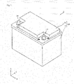
- Fig. 1 is a perspective view showing an external appearance of the energy storage apparatus 1 according to an embodiment of the present invention.
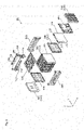
- Fig. 2 is an exploded perspective view showing respective constitutional elements of the energy storage apparatus 1 according to the embodiment of the present invention in a disassembled state.
- a Z axis direction is indicated as the vertical direction, and the description is made hereinafter using the Z axis direction as the vertical direction.
- the Z axis direction is not the vertical direction depending on a mode of use and hence, the Z axis direction is not limited to the vertical direction. The same goes for drawings which are referenced hereinafter.
- the energy storage apparatus 1 is an apparatus which can charge electricity from the outside of the energy storage apparatus 1 therein or can discharge electricity to the outside of the energy storage apparatus 1.
- the energy storage apparatus 1 is a battery module used for power storage application, power source application or the like.
- the energy storage apparatus 1 includes an outer case 10 formed of a first outer case 11 and a second outer case 12, and also includes an energy storage unit 20, a holder 30, bus bars 41, 42, thermistors 50 and the like which are accommodated in the inside of the outer case 10.
- the outer case 10 is a container (module case) having a rectangular shape (box shape) which forms an outer case of the energy storage apparatus 1.
- the outer case 10 is disposed outside the energy storage unit 20, the holder 30, the bus bars 41, 42 and the thermistors 50, and allows the arrangement of the energy storage unit 20 and the like at predetermined positions thus protecting the energy storage unit 20 and the like from an impact or the like.
- the outer case 10 is made of an insulating resin material such as polycarbonate (PC), polypropylene (PP), polyethylene (PE), a polyphenylene sulfide resin (PPS), polybutylene terephthalate (PBT) or an acrylonitrile butadiene styrene (ABS) resin.
- PC polycarbonate
- PP polypropylene
- PE polyethylene
- PPS polyphenylene sulfide resin
- PBT polybutylene terephthalate
- ABS acrylonitrile butadiene styrene
- the outer case 10 includes: the first outer case 11 which forms a lid portion of the outer case 10; and the second outer case 12 which forms a body portion of the outer case 10.
- the first outer case 11 is a cover member having a flat rectangular shape which closes an opening of the second outer case 12.
- a positive electrode external terminal 13 and a negative electrode external terminal 14 are mounted on the first outer case 11.
- the energy storage apparatus 1 charges electricity from the outside therein through the positive electrode external terminal 13 and the negative electrode external terminal 14 or discharges electricity to the outside through the positive electrode external terminal 13 and the negative electrode external terminal 14.
- the second outer case 12 is a bottomed rectangular cylindrical housing having the opening, and houses the energy storage unit 20, the holder 30, the bus bars 41, 42, the thermistors 50 and the like therein.
- the outer case 10 has strip-shaped ribs 12r on a surface thereof which oppositely faces a spacer 300 (spacer 320) described later.
- the second outer case 12 has the ribs 12r.
- the ribs 12r are elongated projecting portions extending in the Z axis direction, and a plurality of ribs 12r are arranged at predetermined intervals in a Y axis direction. Since the outer case 10 has the ribs 12r as described above, the resistance of the outer case 10 against deformation can be enhanced.
- the first outer case 11 and the second outer case 12 may be made of the same material, or may be made of different materials.
- the first outer case 11 is configured to be separable into two members in the vertical direction (Z axis direction), and the electric equipment are arranged between two members. With such a configuration, it is possible to protect electric equipment from an impact or the like and, at the same time, it is possible to prevent the electric equipment from coming into contact with the external metal member and the like.
- a control circuit is mounted on the printed circuit board.
- the control circuit is connected to energy storage devices 100 in the inside of the energy storage unit 20 described later through wirings.
- the control unit acquires, monitors and controls various information such as a charge state, a discharge state, a voltage value, a current value, a temperature and the like of the energy storage device 100, performs an ON/OFF control of the relay, and performs the communication between the energy storage apparatus 1 and other equipment.
- the above-mentioned temperature of the energy storage device 100 is a temperature acquired by using the thermistor 50.
- the control circuit is connected to the thermistor 50 mounted on the energy storage device 100 in a contact state through a wiring (lead wire), and acquires a temperature of the energy storage device 100 by converting information (resistance value) transmitted from the thermistor 50 into a temperature.
- the energy storage unit 20 includes a plurality of energy storage devices 100 (twelve energy storage devices 100 in this embodiment) and a plurality of bus bars 200, and is electrically connected to the positive electrode external terminal 13 and the negative electrode external terminal 14 mounted on the first outer case 11.
- a positive electrode terminal of any one of the plurality of energy storage devices 100 is electrically connected to the positive electrode external terminal 13 through the bus bars 200.
- a negative electrode terminal of any one of the plurality of energy storage devices 100 is electrically connected to the negative electrode external terminal 14 through the bus bars 200.
- the energy storage unit 20 is disposed in the inside of the second outer case 12 such that the plurality of energy storage devices 100 are arranged in a row in an X axis direction in a state where each energy storage device 100 is mounted vertically.
- the energy storage unit 20 is accommodated in the outer case 10 in a state where the energy storage unit 20 is covered by the first outer case 11 from above.
- the detailed description of the configuration of the energy storage unit 20 and the detailed description of the configuration for fixing the energy storage unit 20 and the outer case 10 to each other are made later.
- the holder 30 is an electric component tray which can hold electric components such as the bus bars 41, 42, relays, wires (not shown in the drawing) and the like, can provide insulation between the bus bars 41, 42 and the like and other members, and can restrict the positions of the bus bars 41, 42 and the like. Particularly, the holder 30 performs the positioning of the bus bars 41, 42 with respect to the bus bars 200 in the inside of the energy storage unit 20, the positive electrode external terminal 13 and the negative electrode external terminal 14.
- the holder 30 is mounted on an upper side (a plus side in the Z axis direction) of the energy storage unit 20 and is positioned with respect to the energy storage unit 20.
- the bus bars 41, 42 are mounted on the holder 30 and are positioned with respect to the holder 30.
- the first outer case 11 is disposed on the holder 30. With such a configuration, the bus bars 41, 42 are positioned with respect to the bus bars 200 disposed in the inside of the energy storage unit 20 and the positive electrode external terminal 13 and the negative electrode external terminal 14 mounted on the first outer case 11.
- the holder 30 also has a function of holding the thermistors 50. Opening portions are formed in the holder 30. By inserting the thermistors 50 into the opening portions respectively and by rotating the thermistors 50, the thermistors 50 are positioned with respect to the energy storage devices 100, and are fixed in a state where the thermistors 50 are pressed to the energy storage devices 100.
- the holder 30 is made of an insulating resin material such as PC, PP, PE, PPS, PBT or an ABS resin, for example.
- the holder 30 may be made of any material provided that the holder 30 is made of a material having insulating property.
- the bus bars 41, 42 electrically connect the bus bars 200 disposed in the energy storage unit 20 and the positive electrode external terminal 13 and the negative electrode external terminal 14 mounted on the first outer case 11 to each other.
- the bus bar 41 is a conductive member which electrically connects the bus bar 200 disposed on one end in the energy storage unit 20 and the positive electrode external terminal 13 to each other.
- the bus bar 42 is an electrical conductive member which electrically connects the bus bar 200 disposed on the other end in the energy storage unit 20 and the negative electrode external terminal 14 to each other.
- the bus bars 41, 42 are electrical conductive members and are made of copper, for example. However, materials for forming the bus bars 41, 42 are not particularly limited. The bus bars 41, 42 may be made of the same material or different materials.
- the thermistors 50 are temperature sensors mounted on the energy storage devices 100.
- the thermistors 50 are mounted on the energy storage devices 100 in a state where the thermistors 50 are pressed to lid portions of the energy storage devices 100 respectively, and measure temperatures of the energy storage devices 100.
- two thermistors 50 are disposed in two energy storage devices 100.
- the thermistors 50 are mounted on the holder 30 after the holder 30 is mounted on the energy storage devices 100, the thermistors 50 are disposed in a state where the thermistors 50 are positioned with respect to the energy storage devices 100 and are pressed to the energy storage devices 100.
- the principle that the thermistor 50 measures a temperature is substantially equal to the principle that a conventional thermistor measures a temperature and hence, the detailed description of the principle is omitted.
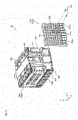
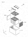
- Fig. 3 is an exploded perspective view showing respective constitutional elements of the energy storage unit 20 according to the embodiment of the present invention in a disassembled state.
- the energy storage unit 20 includes: the plurality of energy storage devices 100; the plurality of bus bars 200; a plurality of spacers 300 (a plurality of spacers 310, and a pair of spacers 320); a pair of sandwiching members 400; a plurality of binding members 500; a bus bar frame 600; and a heat shielding plate 700.
- the energy storage device 100 is a secondary battery (battery cell) which can charge or discharge electricity.
- the energy storage device 100 is a nonaqueous electrolyte secondary battery such as a lithium ion secondary battery.
- the energy storage device 100 has a flat rectangular shape, and is disposed adjacently to the spacer 310.
- the plurality of energy storage devices 100 and the plurality of spacers 310 are arranged in a row in the X axis direction such that the energy storage device 100 and the spacer 310 are alternately arranged.
- twelve energy storage devices 100 and eleven spacers 310 are arranged such that the energy storage device 100 and the spacer 310 are arranged alternately and adjacently to each other.
- the energy storage device 100 is not limited to a nonaqueous electrolyte secondary battery, and may be a secondary battery other than a nonaqueous electrolyte secondary battery, or may be a capacitor. Further, the energy storage device 100 may be a primary battery which a user can use stored electricity without charging.
- the energy storage device 100 includes a container 110, a positive electrode terminal 120 and a negative electrode terminal 130.
- An electrode assembly energy storage element
- current collectors a positive electrode current collector and a negative electrode current collector
- a liquid such as an electrolyte solution (nonaqueous electrolyte) is sealed in the container 110.
- an electrolyte solution nonaqueous electrolyte
- the container 110 is formed of: a bottomed container body made of metal and having a rectangular cylindrical shape; and a metal-made lid portion which closes an opening of the container body.
- the container 110 is configured such that the inside of the container 110 can be hermetically sealed by joining the lid portion and the container body to each other by welding or the like after the electrode assembly and the like are accommodated in the inside of the container 110.
- the container 110 is a rectangular parallelepiped container having a lid portion disposed on the plus side in the Z axis direction in the drawing, long side surfaces disposed on side surfaces of the container on both sides in the X axis direction, short side surfaces disposed on side surfaces of the container on both sides in the Y axis direction, and a bottom surface disposed on a minus side in the Z axis direction.
- a material for forming the container 110 is not particularly limited, it is preferable that the container 110 be made of weldable metal such as stainless steel, aluminum or an aluminum alloy, for example.
- the positive electrode terminal 120 is an electrode terminal electrically connected to a positive electrode of the electrode assembly through the positive electrode current collector.
- the negative electrode terminal 130 is an electrode terminal electrically connected to a negative electrode of the electrode assembly through the negative electrode current collector. Both the positive electrode terminal 120 and the negative electrode terminal 130 are mounted on the lid portion of the container 110.
- the positive electrode terminal 120 and the negative electrode terminal 130 are metal-made electrode terminals through which electricity stored in the electrode assembly is discharged to a space outside the energy storage device 100, and through which electricity is introduced into a space inside the energy storage device 100 for storing electricity in the electrode assembly.
- the energy storage devices 100 are disposed in a state where the positive electrode terminals 120 and the negative electrode terminals 130 are directed upward.
- the bus bars 200 are bus bars electrically connected to the plurality of respective energy storage devices 100 in the energy storage unit 20.
- the bus bars 200 are conductive members electrically connected to the respective electrode terminals which the plurality of energy storage devices 100 have.
- the bus bars 200 electrically connect positive electrode terminals which the plurality of energy storage devices 100 have respectively to each other, and electrically connect negative electrode terminals which the plurality of energy storage devices 100 have respectively to each other.
- the bus bars 200 are disposed on surfaces of the respective electrode terminals which the plurality of respective energy storage devices 100 have, and are connected (joined) to the electrode terminals.
- bus bars 200 are disposed, and twelve energy storage devices 100 are disposed such that four sets of energy storage devices 100 each of which is formed of three energy storage devices 100 connected parallel to each other are connected in series by five bus bars 200.
- the bus bars 200 disposed on end portions are connected to the bus bars 41, 42 described above so that the bus bars 200 are electrically connected to the positive electrode external terminal 13 and the negative electrode external terminal 14.
- the bus bars 200 are electrical conductive members made of aluminum, for example.
- a material for forming the bus bars 200 is not particularly limited. All bus bars 200 may be made of the same material, or some bus bars 200 may be made of a material different from a material for forming other spacers.
- the spacers 300 include the plurality of spacers 310 and the pair of spacers 320.
- the spacers 300 are made of an insulating resin such as PC, PP, PE, PPS, PBT or an ABS resin, for example.
- the spacers 310, 320 may be made of any material provided that the spacers 310, 320 are made of a material having insulating property. All of the spacers 310, 320 may be made of the same material, or some spacers 310, 320 may be made of a material different from a material for forming other spacers.
- the spacer 310 is a plate-like member which is disposed on a side (a plus side or a minus side in the X axis direction) of the energy storage device 100, and provides insulation between the energy storage device 100 and other members.
- the spacer 310 is arranged between two energy storage devices 100 disposed adjacently to each other, and provides insulation between two energy storage devices 100.
- eleven spacers 310 are arranged such that each spacer 310 is disposed between each two energy storage devices 100 of twelve energy storage devices 100.
- the spacer 310 is formed such that the spacer 310 covers approximately half of a front surface side or a back surface side of the energy storage device 100 (an approximately half of the front surface side or the back surface side of the energy storage device 100 when the energy storage device 100 is divided in two in the X axis direction).
- Recessed portions are formed on both surfaces (both surfaces in the X axis direction) of the spacer 310 on the front surface side and the back surface side respectively, and an approximately half of the energy storage device 100 is inserted into the recessed portions.
- the spacers 310 disposed on sides of the energy storage device 100 cover the most part of the energy storage device 100.
- the spacer 310 is formed such that a portion of the energy storage device 100 at which the thermistor 50 is positioned is not covered by the spacer 310 thus allowing the thermistor 50 to come into contact with the energy storage device 100.
- the spacer 320 is a plate-like member which is disposed between the sandwiching member 400 and the outer case 10, and provides insulation between the sandwiching member 400 and the outer case 10.
- the spacer 320 is disposed between the sandwiching member 400 and a side wall of the second outer case 12 (a body portion of the outer case 10).
- the spacer 320 is arranged at a position approximately parallel to the sandwiching member 400 and the side wall of the second outer case 12.
- the side wall of the second outer case 12 is a wall positioned on a side of the energy storage device 100 out of the plurality of walls which constitute the second outer case 12.
- the side wall is a wall which forms a cylindrical body of the second outer case 12 having a bottomed rectangular cylindrical shape.
- the spacer 320 also has a function as a buffer member which protects the energy storage unit 20 when an impact is applied to the outer case 10 from the outside or the like.
- the pair of spacers 320 is disposed between the pair of sandwiching members 400 and the outer case 10 such that the pair of spacers 320 sandwiches the pair of sandwiching members 400 from both sides.
- the pair of spacers 320 insulates the energy storage devices 100 and the like disposed in the energy storage unit 20, and also protects the energy storage devices 100 and the like from an impact from the outside.
- Two spacers 320 sandwich the energy storage devices 100 and are disposed between two sandwiching members 400 which are positioned so as to oppositely face each other and the outer case 10 respectively.
- these spacers 320 are fixed to spacer mounting portions 710 of the heat shielding plate 700 respectively.
- the spacers 320 are accommodated in the outer case 10 in a state where the spacers 320 are fixed to the energy storage devices 100 respectively.
- the spacer 320 may not be mounted on the heat shielding plate 700.
- the spacer 320 may be mounted on the sandwiching member 400, or may be disposed between the sandwiching member 400 and the outer case 10 without being mounted on other members.
- the configuration of the spacer 320 and the configuration where the spacer 320 is fixed are described in detail later.
- the sandwiching members 400 and the binding members 500 are members which press the energy storage devices 100 from the outside in the stacking direction of the electrode assembly of the energy storage device 100.
- the sandwiching members 400 and the binding members 500 sandwich the plurality of energy storage devices 100 from both sides in the stacking direction thus pressing each energy storage device 100 included in the plurality of energy storage devices 100 from both sides.
- the stacking direction of the electrode assembly of the energy storage devices 100 means the direction that positive electrodes, negative electrodes and separators of the electrode assembly are stacked, and is equal to the direction (X axis direction) that the plurality of energy storage devices 100 are arranged in a row.
- the plurality of energy storage devices 100 are arranged in a row in the stacking direction of the electrode assembly of the energy storage devices 100.
- the sandwiching members 400 are flat plate-like members (end plates) disposed on both sides of the unit formed of the plurality of energy storage devices 100 in the X axis direction respectively.
- the sandwiching members 400 hold the plurality of energy storage devices 100 and the plurality of spacers 310 by sandwiching the plurality of energy storage devices 100 and the plurality of spacers 310 from both sides in the arrangement direction (X axis direction) of the plurality of energy storage devices 100 and the plurality of spacers 310.
- the sandwiching member 400 is made of a metal (conductive) material such as stainless steel or aluminum, for example, from a viewpoint of strength or the like of the sandwiching member 400.
- a material for forming the sandwiching member 400 is not limited to such a material, and may be made of an insulating material having high strength, for example.
- the binding members 500 are elongated flat-plate-like members (binding bars) where both ends of each binding member 500 are mounted on the sandwiching members 400 thus allowing the binding members 500 to bind the plurality of energy storage devices 100.
- the binding members 500 are disposed so as to straddle over the plurality of energy storage devices 100 and the plurality of spacers 310, and apply a binding force to the plurality of energy storage devices 100 and the plurality of spacers 310 in the arrangement direction (X axis direction) of the plurality of energy storage devices 100 and the plurality of spacers 310.
- two binding members 500 are disposed on both sides (both sides in the Y axis direction) of the unit formed of the plurality of energy storage devices 100, and two binding members 500 bind the plurality of energy storage devices 100 by sandwiching the plurality of energy storage devices 100 from both sides.
- the binding members 500 are preferably made of a metal material such as stainless steel or aluminum, for example.
- the binding members 500 may be made of a material other than metal.
- the bus bar frame 600 is a member which can provide insulation between the bus bars 200 and other members, and can regulate the positions of the bus bars 200. Particularly, the bus bar frame 600 performs the positioning of the bus bars 200 with respect to the plurality of energy storage devices 100 disposed in the energy storage unit 20.
- the bus bar frame 600 is placed above (on the plus side in the Z axis direction of) the unit formed of the plurality of energy storage devices 100, and is positioned with respect to the plurality of energy storage devices 100.
- the bus bar frame 600 is made of an insulating resin material such as PC, PP, PE, PPS, PBT or an ABS resin, for example.
- the bus bar frame 600 may be made of any material provided that the bus bar frame 600 is made of a material having insulating property.
- two thermistor-use opening portions are formed.
- the thermistor-use opening portions are through holes into which two thermistors 50 are inserted respectively.
- Two thermistors 50 are respectively inserted into two thermistor-use opening portions, and are brought into contact with the lid portions of the containers 110 of the energy storage devices 100.
- the heat shielding plate 700 is a plate-like member having heat insulating property which is disposed in the inside of a flow passage for a gas to be discharged through gas release valves of the energy storage devices 100.
- the heat shielding plate 700 is disposed above the bus bar frame 600 such that the heat shielding plate 700 is positioned above the gas release valves of the energy storage devices 100.
- the heat shielding plate 700 protects electric equipment such as a printed circuit board disposed above the energy storage unit 20 from heat of the gas.
- the heat shielding plate 700 is made of a metal material having low thermal conductivity such as stainless steel.
- a material for forming the heat shielding plate 700 is not limited to such a metal material, and it is sufficient that the heat shielding plate 700 be made of a material having high heat resistance and low thermal conductivity.
- the heat shielding plate 700 may be made of a resin such as PPS or PBT reinforced with glass fibers, ceramic or the like.
- the heat shielding plate 700 has the spacer mounting portions 710 on both end portions in the longitudinal direction of the heat shielding plate 700, and two spacers 320 are mounted on the spacer mounting portions 710 respectively.
- the heat shielding plate 700 is not limited to the configuration where the heat shielding plate 700 has the spacer mounting portions 710, and may be configured to be positioned above the gas release valves of the energy storage devices 100, for example, may be a plate like member disposed above the bus bar frame 600.
- the detailed configuration of the spacer 320 is described together with the configuration where the spacer 320 is fixed (that is, the configuration where the spacer 320 is mounted on the spacer mounting portion 710).
- Two spacers 320 have the same configuration and hence, hereinafter, the description is made with respect to matters relating to one spacer 320, and the description with respect to matters relating to the other spacer 320 is omitted.
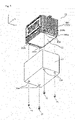
- Fig. 4 is an exploded perspective view showing a state where the spacer 320 is disassembled from the energy storage unit 20 according to the embodiment of the present invention.
- Fig. 4 only one spacer 320 (the spacer 320 disposed on the plus side in the X axis direction) out of two spacers 320 is shown in a disassembled state from the energy storage unit 20.
- Fig. 5 is a perspective cross-sectional view showing a portion of the spacer 320 according to the embodiment of the present invention by cutting the spacer 320.
- Fig. 6 is an enlarged perspective view showing a configuration of the spacer mounting portion 710 of the heat shielding plate 700 according to the embodiment of the present invention in an enlarged manner.
- the spacer 320 shown in these drawings is formed so as to cover a surface of the sandwiching member 400 on a side opposite to the energy storage device 100.
- the spacer 320 is formed substantially equal to the sandwiching member 400 or slightly larger than the sandwiching member 400 in size as viewed from an arrangement direction of the spacer 320 and the sandwiching member 400 (as viewed in the X axis direction).
- the spacer 320 is disposed between the sandwiching member 400 and a portion of the outer case 10 which oppositely faces the sandwiching member 400. Accordingly, the insulating property between sandwiching member 400 and the outer case 10 can be enhanced by the spacer 320, and a protection performance of protecting the energy storage devise 100 from an impact from the outside can be enhanced.
- openings 320b described later are formed in the spacer 320 to enable fixing of the sandwiching member 400 to the outer case 10.
- two through holes 320a into which two screws 301 are inserted (through which the screws 301 pass) are formed in the spacer 320.
- the spacer 320 is mounted on the spacer mounting portion 710 of the heat shielding plate 700 by screws 301 inserted into the through holes 320a and through holes 711a (see Fig. 6 ) formed in the spacer mounting portion 710. With such a configuration, the spacer 320 is positioned with respect to the energy storage device 100 in the inside of the outer case 10.
- a method of mounting the spacer 320 on the spacer mounting portion 710 is not particularly limited, and the spacer 320 may be mounted on the spacer mounting portion 710 by engaging, fitting or the like.
- the spacer 320 has the openings 320b.
- a fastening portion of the outer case 10 with the sandwiching member 400 is disposed in the inside of the opening 320b.
- the fastening portion is inserted into and is disposed in the opening 320b.
- the fastening of the outer case 10 with the sandwiching member 400 in the inside of the opening 320b is described later.
- the spacer 320 also has recessed portions 320c in which the ribs 12r of the outer case 10 are disposed. In a state where the energy storage unit 20 is accommodated in the outer case 10, the ribs 12r are disposed in the recessed portions 320c. The configuration where the ribs 12r are disposed in the recessed portions 320c is described later.
- the spacer 320 has rigidity which allows breaking or deformation of the spacer 320 when an impact is applied to the spacer 320 from a viewpoint of enhancing performance of protecting the energy storage devices 100 from an impact from the outside.
- the spacer 320 is broken or deformed so that the impact is absorbed by the spacer 320 whereby the energy storage devices 100 are protected.
- the spacer 320 has rigidity smaller than rigidity of the sandwiching member 400.
- the rigidity of the spacer 320 and the rigidity of the sandwiching member 400 can be evaluated by using Computer Aided Engineering (CAE) analysis or the like where, for example, a shape of the spacer 320 and a shape of the sandwiching member 400 are prepared as three-dimensional (3D) models using a Computer Aided Design (CAD) or a shape of the spacer 320 and a shape of the sandwiching member 400 are read from actual products by 3D scanning.
- CAE Computer Aided Engineering
- the spacer 320 includes: a base plate 321 which extends in an oppositely facing manner with the sandwiching member 400; and projecting portions 322 which project from the base plate 321.
- the base plate 321 is a plate-like member having an approximately rectangular shape which extends in an oppositely facing manner with the sandwiching member 400.
- the base plate 321 is disposed in an overlapping manner with the whole energy storage device 100 as viewed in a plan view of the base plate 321 (as viewed in the X axis direction).
- a shape of the base plate 321 is not limited to an approximately rectangular shape.
- the base plate 321 is formed with a wall thickness smaller than a wall thickness of the sandwiching member 400.
- the sandwiching member 400 is a laminated body formed of a resin-made end plate and a metal-made end plate
- the base plate 321 is formed with a wall thickness smaller than a wall thickness of the resin-made end plate.
- the base plate 321 is formed with a wall thickness smaller than a wall thickness of the resin-made end plate so that in the case where the base plate 321 and the resin-made end plate are made of the same material, rigidity of the base plate 321 becomes smaller than rigidity of the resin-made end plate. Accordingly, an impact applied to the outer case 10 can be absorbed by the base plate 321 due to collapsing of the base plate 321.
- peripheral portions 321a of the base plate 321 around the through hole 320a are formed with a wall thickness larger than a wall thickness of other portions of the base plate 321.
- the peripheral portions 321a with a large wall thickness, it is possible to suppress the occurrence of unexpected breaking or the like of the base plate 321 due to mounting of the spacer 320 using the screws 301. Breaking of the base plate 321 due to mounting of the spacer 320 can be suppressed while lowering rigidity of the portions of the base plate 321 other than the peripheral portions 321a for absorbing an impact.
- the projecting portions 322 are portions projecting from the base plate 321, and are integrally formed with the base plate 321, for example.
- the projecting portions 322 project from the base plate 321 toward a side opposite to the sandwiching member 400 (that is, toward outside of the energy storage apparatus 1).
- the base plate 321 is disposed on a sandwiching member 400 side of the projecting portions 322.
- a projecting direction of the projecting portions 322 is not particularly limited, and the projecting portions 322 may project toward the sandwiching member 400.
- the base plate 321 is positioned on a sandwiching member 400 side and hence, mounting operability of the spacer 320 can be enhanced.
- the projecting portion 322 has a plurality of first wall portions 323 extending along a surface (in the drawing, a surface on the plus side in the X axis direction) of the base plate 321, and a plurality of second wall portions 324 extending between the plurality of first wall portions 323.
- the plurality of first wall portions 323 and the plurality of second wall portions 324 are arranged approximately orthogonal to each other.
- the arrangement of the first wall portions 323 and the second wall portions 324 is not limited to the substantially approximately orthogonal.
- the first wall portions 323 and the second wall portions 324 may be arranged in a honeycomb form together with third wall portions (not shown in the drawing).
- the plurality of first wall portions 323 are wall-shaped portions erected from the base plate 321.
- the plurality of first wall portions 323 extend over the whole width of the base plate 321 in the Z axis direction, and are arranged at predetermined intervals in the Y axis direction.
- the plurality of first wall portions 323 are arranged at intervals substantially equal to intervals of the ribs 12r of the outer case 10 such that one rib 12r is positioned between two first wall portions 323 disposed adjacently to each other in a state where the energy storage unit 20 is accommodated in the outer case 10.
- the plurality of second wall portions 324 are wall-shaped portions erected from the base plate in the same manner as the first wall portions 323.
- the plurality of second wall portions 324 extend over the whole width of the base plate 321 in the Y axis direction, and are arranged at predetermined intervals in the Z axis direction.
- each second wall portion 324 has low-height portions where a recessed portion 320c in which the rib 12r is arranged is formed. Each low-height portion forms a cutout in the second wall portion 324.
- portions other than the recessed portions 320c are formed with substantially the same height as the first wall portions 323 (a width in the X axis direction), and portions corresponding to the recessed portions 320c are formed with a height lower than a height of the first wall portions 323.
- the first wall portions 323 and the second wall portions 324 are formed with a wall thickness smaller than a wall thickness of the base plate 321 at connecting portions with the base plate 321, for example. Further, the first wall portions 323 and the second wall portions 324 are formed such that the wall thickness of the first wall portion 323 and the wall thickness of the second wall portion 324 are gradually decreased in the projecting direction. With such a configuration, the first wall portions 323 and the second wall portions 324 are collapsed more easily at an outer case 10 side and hence, the spacer 320 can further effectively absorb an impact applied to the outer case 10. Protection performance of the spacer 320 for protecting the energy storage devices 100 from an impact from the outside can be enhanced.
- the first wall portions 323 and the second wall portions 324 may be made of the same material as the base plate 321, or may be made of a material different from a material for forming the base plate 321.
- the arrangement of the first wall portions 323 and the second wall portions 324 is not particularly limited.
- the difference in density may be provided in the arrangement of the wall portions such that the wall portions are arranged more densely at the center portion of the base plate 321 than at the peripheral portion of the base plate 321.
- arrangement intervals of the first wall portions 323 and arrangement intervals of the second wall portions 324 may be set equal to each other or may be set different from each other.
- a plurality of spaces S3 are formed in the inside of the spacer 320.
- Such spaces S3 in the inside of the spacer 320 act as spaces for absorbing an impact applied to the outer case 10 and hence, the protection performance of the spacer 320 for protecting the energy storage devices 100 from an impact from the outside can be enhanced.
- Fig. 6 is an enlarged perspective view showing the configuration of the spacer mounting portion 710 of the heat shielding plate 700 according to the embodiment of the present invention in an enlarged manner.
- the spacer mounting portion 710 includes first contact portions 711 which are brought into contact with the spacer 320, and a second contact portion 712 which is brought into contact with the sandwiching member 400.
- the spacer mounting portion 710 is fixed to the sandwiching member 400 by screws 701.
- the first contact portions 711 are portions which are formed on both sides in the lateral direction of the heat shielding plate 700 (both sides in the Y axis direction), and project toward a side opposite to the sandwiching member 400 from the second contact portion 712.
- the pair of first contact portions 711 projects from both sides of the second contact portion 712 in the Y axis direction toward the spacer 320, and is brought into contact with the spacer 320 in a state where the pair of first contact portions 711 is bent along the spacer 320.
- a through hole 711a which is a through hole into which the screw 301 is inserted is formed in each first contact portion 711.
- the second contact portion 712 is a portion arranged in a state where the second contact portion 712 is brought into contact with the sandwiching member 400.
- a through hole 712a into which the screw 701 is inserted is formed in the second contact portion 712.
- spaces S7 are formed between the sandwiching member 400 and the first contact portions 711.
- the sandwiching member 400 and the spacer 320 are arranged in a spaced-apart manner.
- Such spaces S7 formed between the sandwiching member 400 and the spacer 320 form spaces for absorbing an impact applied to the outer case 10 and hence, the protection performance of the spacer 320 for protecting the energy storage devices 100 from an impact from the outside can be further enhanced.
- the spacer 320 is mounted on the spacer mounting portion 710. Further, the energy storage unit 20 is accommodated in the outer case 10 in a state where the spacers 320 are mounted on the energy storage unit 20, and is fixed to the outer case 10 as described hereinafter.
- Fig. 7 is a perspective view showing a state where the energy storage unit 20 according to the embodiment of the present invention and the outer case 10 (second outer case 12) are fixed to each other.
- the second outer case 12 has mounting portions 12a for fastening tools 21.
- Mounting portions 12a are recessed portions recessed toward the sandwiching members 400, and the sandwiching members 400 are fixed to the mounting portions 12a.
- the energy storage unit 20 is fixed to the outer case 10 in a state where the energy storage unit 20 is accommodated in the second outer case 12.
- each mounting portion 12a a through hole (not shown in the drawing) in which the fastening tool 21 is inserted is formed in each mounting portion 12a.
- the mounting portions 12a constitute fastening portions of the outer case 10 to be fastened with the sandwiching member 400.
- the fastening tools 21 are bolts for fixing the sandwiching member 400 to the outer case 10 (in this embodiment, the second outer case 12), for example.
- the fastening tools 21 is not limited to bolts, and may be screws or the like.
- the energy storage unit 20 is fixed to the outer case 10.
- the energy storage unit 20 is fixed to the outer case 10 also by an adhesive material 22 disposed between the energy storage device 100 and the outer case 10.
- the adhesive material 22 is a double-coated adhesive tape for fixing the energy storage devices 100 disposed in the inside of the energy storage unit 20 to the outer case 10 at a position different from positions where the fastening tools 21 are disposed, for example.
- the adhesive material 22 is not limited to a double-coated adhesive tape, and may be an adhesive agent.
- the adhesive material 22 may be an adhesive material having the surface fastener structure which allows the adhesion in a detachable manner referred to as Magic Tape (registered trademark) or Velcro tape (registered trademark).
- the mounting portions 12a (fastening portions) of the outer case 10 are disposed in the inside of the openings 320b of the spacer 320.
- the mounting portions 12a are fixed (fastened) to the sandwiching members 400 exposed from the openings 320b using fastening tools 21.
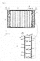
- Fig. 8 is a perspective view showing a configuration of the energy storage unit 20 according to the embodiment of the present invention in a state where the energy storage unit 20 is accommodated in the outer case 10 (second outer case 12).
- Fig. 9 is a cross-sectional view showing a configuration of the energy storage unit 20 according to the embodiment of the present invention in a state where the energy storage unit 20 is accommodated in the outer case 10 (second outer case 12).
- (a) of Fig. 9 is a whole cross-sectional view of the energy storage unit 20 taken along line IX-IX in Fig. 8 which is a perspective view
- (b) of Fig. 9 is a view showing a region surrounded by a chained line in (a) of Fig. 9 in an enlarged manner.
- the illustration of members other than the second outer case 12 and the energy storage unit 20 is omitted.
- each recessed portion 320c has a shape where the recessed portion 320c is recessed toward a projecting direction of the rib 12r with a size slightly larger than a profile of the rib 12r such that the rib 12r is positioned in the inside of the recessed portion 320c.
- the spacer 320 and the second outer case 12 are disposed in a slightly spaced apart manner from each other.
- the relationship of d2 ⁇ d3 is established.
- the second outer case 12 and the spacer 320 are disposed such that a gap formed between the second outer case 12 and the spacer 320 is set small at other positions compared to the positions where the ribs 12r are formed.
- deformation resistance of the second outer case 12 is enhanced by the ribs 12r and hence, even when an impact is applied to the second outer case 12, provided that the ribs 12r are not damaged, the deformation of the second outer case 12 is suppressed.
- the second outer case 12 is firstly brought into contact with the spacer 320 at the portions different from the portions where the ribs 12r are formed. Accordingly, the second outer case 12 is brought into contact with the spacer 320 with a relatively large area and hence, the concentration of a stress to a specific portion of the spacer 320 due to applying of the impact can be suppressed. Accordingly, protection performance of the spacer 320 from an impact from the outside can be enhanced.
- the plate-like spacer 320 is disposed between the end plate (in this embodiment, the sandwiching member 400) and the outer case 10. Accordingly, an impact applied to the outer case 10 can be absorbed by breaking or deformation of the spacer 320.
- breaking or deformation of the sandwiching member 400 can be suppressed by breaking or deformation of the spacer 320 per se. Accordingly, an impact applied to the energy storage device 100 through the sandwiching member 400 can be suppressed. As a result, it is possible to protect the energy storage device 100 from the impact.
- the spacer 320 is disposed between the sandwiching member 400 and the body portion (in this embodiment, the second outer case 12) of the outer case 10 and hence, it is possible to protect the energy storage device 100 from an impact applied to the body portion.
- Such a configuration is particularly useful in an in-use state where the lid portion (in this embodiment, the first outer case 11) is disposed on an upper side in a vertical direction.
- the number of cases where an impact is applied to the second outer case 12 is larger than the number of cases where an impact is applied to the first outer case 11. Accordingly, by disposing the spacer 320 between the sandwiching member 400 and the second outer case 12, it is possible to effectively protect the energy storage device 100 from an impact.
- the spacer 320 is disposed at the position which is substantially parallel to the sandwiching member 400 and hence, the sandwiching member 400 can receive an impact applied to the outer case 10 by a face by way of the spacer 320. Accordingly, it is possible to protect the energy storage device 100.
- two spacers 320 sandwich the energy storage devices 100 and hence, it is possible to protect the energy storage devices 100 more securely.
- the spacer 320 includes the projecting portions 322 projecting from the base plate 321 and hence, a load generated by an impact applied to the outer case 10 is likely to be larger at the projecting portions 322 than at the base plate 321. Accordingly, the impact applied to the outer case 10 can be absorbed by collapsing of the projecting portions 322 and hence, it is possible to protect the energy storage device 100.
- the base plate 321 is disposed on the sandwiching member 400 side of the projecting portion 322 and hence, an impact applied to the outer case 10 is received by the projecting portion 322 and then is transmitted to the base plate 321. Accordingly, the transmission of the impact to the sandwiching member 400 side can be suppressed and hence, it is possible to protect the energy storage device 100. Further, in the configuration where the spacer 320 is fixed to the energy storage device 100, by disposing the base plate 321 on the sandwiching member 400 side, the spacer 320 can be easily fixed to the energy storage device 100.
- the projecting portion 322 includes the plurality of first wall portions 323 and the plurality of second wall portions 324 extending between the plurality of first wall portions 323. Accordingly, the plurality of first wall portions 323 and the plurality of second wall portions 324 are reinforced by each other. Accordingly, it is possible to suppress the occurrence of an unexpected damage on the projecting portion 322 due to vibration or the like of the energy storage apparatus 1.
- the ribs 12r of the outer case 10 are disposed in the inside of the recessed portions 320c formed on the spacer 320. Accordingly, the spacer 320 can be disposed at a position relatively close to an inner surface of the outer case 10. The spacer 320 having a large size can be disposed in a space between the sandwiching member 400 and the outer case 10. Accordingly, an impact applied to the outer case 10 can be further effectively absorbed by the spacer 320 and hence, it is possible to further securely protect the energy storage device 100.
- the fastening portions (in this embodiment, the mounting portions 12a) of the outer case 10 are disposed in the inside of the openings 320b of the spacer 320 and hence, the fastening portions can be protected by the spacer 320. Accordingly, it is possible to suppress the occurrence of a damage or the like at the fastening portions to which a load is liable to be applied by fastening.
- the energy storage apparatus 1 includes the sandwiching members 400, and the spacers 320 are disposed between the sandwiching members 400 and the outer case 10 respectively.
- the energy storage apparatus may not include the sandwiching members, and the spacer may be disposed between the energy storage devices 100 at end portions among one or more energy storage devices 100 and the outer case 10 respectively.
- the energy storage apparatus having such a configuration is described.
- Fig. 10 is an exploded perspective view showing respective constitutional elements when an energy storage unit 20A according to the modification 1 of the embodiment is disassembled.
- a second outer case 12 of an outer case 10 is also shown.
- the illustration of spacers each of which is disposed between energy storage devices 100 which are disposed adjacently to each other, a heat shielding plate of the energy storage unit 20A and the like are omitted.
- the energy storage unit 20A shown in Fig. 10 includes neither sandwiching members 400 nor binding members 500 compared to the energy storage unit 20 of the embodiment. Accordingly, a plurality of energy storage devices 100 are accommodated in the outer case 10 in a state where the plurality of energy storage devices 100 are not bound to each other. A wall or the like for holding the energy storage devices 100 may be disposed in the inside of the second outer case 12.
- spacers 320A are disposed between the energy storage devices 100 at end portions among one or more energy storage devices 100 (in this modification, twelve energy storage devices 100) and the outer case 10 (in this modification, the second outer case 12) respectively.
- the pair of spacers 320A is disposed between the energy storage devices 100 at both end portions and the outer case 10 so as to sandwich the plurality of energy storage devices 100 from both sides of a unit formed of the plurality of energy storage devices 100. Accordingly, the energy storage devices 100 and the like in the energy storage unit 20 can be insulated, and can be protected from an impact from the outside.
- an advantageous effect substantially equal to the advantageous effect acquired by the above-mentioned embodiment can be acquired.
- the spacers 320A are disposed between the energy storage devices 100 disposed at the end portions and the outer case 10 and hence, an impact applied to the outer case 10 can be absorbed by collapsing of the spacers 320A. Accordingly, it is possible to protect the energy storage device 100 from the impact.
- a modification 2 of the above-mentioned embodiment is described.
- the spacer 320 includes the base plate 321 only on one side of the projecting portions 322.
- a spacer includes a base plate on both sides of projecting portions.
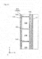
- Fig. 11 is a cross-sectional view showing a configuration of a spacer 320B according to the modification 2 of the embodiment. To be more specific, Fig. 11 is a drawing which corresponds to (b) of Fig. 9 .
- a spacer 320B includes a base plate in the same manner as the above-mentioned embodiment, the spacer 320B includes, as the base plate, a base plate 325 in addition to a base plate 321 which is substantially equal to the base plate of the above-mentioned embodiment.
- the base plate 321 is referred to as a first base plate 321
- the base plate 325 is referred to as a second base plate 325.
- the first base plate 321 is a base plate which is disposed on a sandwiching member 400 side of projecting portions 322 (first wall portions 323 and second wall portions 326).
- the second base plate 325 is a base plate which is disposed on an outer case 10 side (a side wall side of the second outer case 12) of the projecting portions 322 (the first wall portions 323 and the second wall portions 326).
- the second base plate 325 is disposed so as to oppositely face a side wall of the second outer case 12. Accordingly, ribs 12r are not formed on the side wall of the second outer case 12 which oppositely faces the second base plate 325, and recessed portions 320c are not formed on the second wall portion 326 which the projecting portion 322 includes unlike the second wall portion 324 of the above-mentioned embodiment.
- the first wall portion 323 which the projecting portions 322 include has substantially the same configuration as the first wall portion 323 of the above-mentioned embodiment.
- the energy storage apparatus according to this modification having the above-mentioned configuration can acquire an advantageous effect substantially equal to the advantageous effect of the above-mentioned embodiment.
- the spacer 320B includes the base plate on both sides of the projecting portions 322 and hence, the spacer 320B can absorb an impact applied to the outer case 10 further effectively thus protecting the energy storage device 100. Further, for example, in the configuration where the spacer 320B is fixed to the outer case 10, the spacer 320B can be easily fixed to the outer case 10 by mounting the second base plate 325 on the outer case 10.
- the present invention is not limited to the above-mentioned embodiment and the modifications of the embodiment. It should be construed that the embodiment and the modifications of the embodiment disclosed in this specification are only for an exemplifying purpose in all aspects and are not limited.
- the scope of the present invention is not designated by the above-mentioned description but is designated by Claims, and it is intended that all modifications which fall within the meaning and the scope equivalent to Claims are also included in the scope of the present invention.
- the configurations which are made by arbitrarily combining the respective constitutional elements which the above-mentioned embodiment and the modifications of the embodiment include are also included in the scope of the present invention.
- the spacers 320, 320B are fixed to the energy storage device 100.
- the spacer 320A is not fixed to the energy storage device 100 or the like.
- these spacers may be fixed to the outer case 10.
- various methods such as a double-coated adhesive tape, an adhesive agent, a thermal welding, a screwing and the like are considered. In this manner, by fixing the spacer to the outer case 10, it is possible to suppress the occurrence of a phenomenon that the spacer is displaced from the outer case 10 due to an impact or the like from the outside. Also in manufacturing the energy storage apparatus 1, the energy storage apparatus 1 can be easily assembled.
- the energy storage device is configured to include the pair of sandwiching members 400.
- the number of sandwiching members 400 is not particularly limited, and one, or three or more sandwiching members 400 may be provided, for example.
- the sandwiching member 400 may be configured to sandwich the energy storage devices 100 in cooperation with an inner wall of the outer case 10 which oppositely faces the sandwiching member 400 with the energy storage devices 100 sandwiched therebetween. Further, the sandwiching member 400 may not sandwich the energy storage devices 100, and the sandwiching member 400 may be an end plate disposed on a side of the energy storage device 100.
- the energy storage apparatus includes the plurality of energy storage devices 100.
- the number of energy storage devices 100 is not particularly limited provided that at least one or more energy storage devices are provided.
- the spacers 320, 320A are disposed between the energy storage devices 100 at the end portion among one or more energy storage devices 100 and the side walls of the body portion of the outer case 10 (in the above-mentioned description, the second outer case 12).
- the arrangement positions of the spacers 320, 320A are not limited to such positions.
- the spacers 320, 320A may be disposed between the energy storage device 100 at an end portion and a lid portion (in the above-mentioned description, the first outer case 11) of the outer case 10 and between the energy storage device 100 at an end portion and a lower wall of the body portion of the outer case. The same goes also for the modification 2.
- a size of the spacer 320, 320A is not particularly limited provided that the spacer 320, 320A has a plate-like shape. However, from a viewpoint of protecting the energy storage device 100 by absorbing an impact, it is preferable to form the spacer 320, 320A as follows, for example. To be more specific, when the spacer 320, 320A and the energy storage device 100 are viewed in an arrangement direction of the spacer 320, 320A and the energy storage device 100, it is preferable to form the spacer 320, 320A such that the spacer 320, 320A covers the most part of the energy storage device 100 and, further, it is preferable that the spacer 320, 320A cover the electrode assembly in the energy storage device 100. As viewed in the arrangement direction, it is preferable to set a maximum width and a maximum height of the spacer 320, 320A larger than a maximum width and a maximum height of the energy storage device 100. The same goes also for the modification 2.
- spacer 320, 320A it is sufficient for the spacer 320, 320A to have a plate-like shape in a schematic view.
- the spacer 320, 320A may have a projecting portion, a recessed portion or the like in shapes of details. The same goes also for the modification 2.
- a material for forming the spacer 320, 320A is not limited to a material having insulating property.
- the spacer 320, 320A may be made of a material having conductivity. The same goes also for the modification 2.
- the spacer 320, 320A includes the base plate 321 and the projecting portions 322 which project from the base plate 321.
- the spacer 320, 320A is not limited to such a configuration. It is sufficient that the spacer 320, 320A be configured to protect the energy storage device 100 from an impact. For example, it is sufficient for the spacer 320 to have rigidity lower than rigidity of the sandwiching member 400.
- the spacer 320, 320A may be made of a porous and flexible raw material, or may be made of a resin or a raw material having elasticity such as rubber. The same goes also for the modification 2.
- the projecting portions 322 include the plurality of first wall portions 323 and the plurality of second wall portions 324.
- the number of first wall portions 323 and the number of second wall portions 324 are not limited to such numbers.
- the projecting portions 322 may include one first wall portion 323 and one second wall portion 324, for example.
- the second wall portions 324 are configured to extend between the plurality of first wall portions 323 in the above-mentioned embodiment and the modification 1.
- the second wall portions 324 may be configured to extend between some of the first wall portions 323, or may be configured to extend only between each two first wall portions 323 disposed adjacently to each other.
- the projecting portions 322 project from the base plate 321, and the projecting portion 322 may not include at least either one of the first wall portions 323 or the second wall portions 324.
- a shape of the projecting portion 322 is not limited to a wall shape, and may be a columnar shape. The same goes also for the modification 2.
- the projecting portions 322 include the plurality of first wall portions 323, and the plurality of second wall portions 324 extending between the plurality of first wall portions 323.
- the projecting portions 322 may include either one of the plurality of first wall portions 323 or the plurality of second wall portions 324 and may not include the other of the plurality of first wall portions 323 and the plurality of second wall portions 324.
- the projecting portions 322 have the plurality of wall portions and hence, an impact applied to the outer case 10 can be further effectively absorbed by collapsing of the wall portions.
- the extending direction of the plurality of wall portions is not particularly limited.
- the extending direction of the plurality of wall portions may be equal to the extending direction of the first wall portions 323 or the extending direction of the second wall portions 324, or may be other directions. The same goes also for the modification 2.
- the outer case 10 has the ribs 12r on the surface thereof which oppositely faces the spacer 320, 320A.
- the outer case 10 may not have the ribs 12r so that the surface of the outer case 10 may be formed into a flat shape, for example.
- the spacer 320, 320A may not include the recessed portions 320c.
- the spacer 320, 320A may be configured such that the spacer 320, 320A does not include the recessed portions 320c.
- the whole spacer 320, 320A is formed with a small thickness which corresponds to a thickness of the rib 12r.
- the spacer 320, 320A includes the openings 320b in which the fastening portions of the outer case 10 with the sandwiching members 400 are disposed respectively.
- the spacer 320, 320A may not include the openings 320b.
- the space 320, 320A may be configured such that an area of the spacer 320, 320A is decreased in the vertical direction so as to avoid the fastening portions. The same goes also for the modification 2.
- the present invention is applicable to an energy storage apparatus which includes one or more energy storage devices and an outer case and the like.
Description
- The present invention relates to an energy storage apparatus which includes one or more energy storage devices and an outer case.
- Conventionally, in an energy storage apparatus which includes a plurality of energy storage devices, there has been known the configuration where a member is disposed around the plurality of energy storage devices for forming a space to absorb an impact (see
patent document 1, for example). With such a configuration, even when an impact is applied to the energy storage apparatus, the energy storage apparatus can absorb the impact. - Patent Document 1:
JP-A-2013-164969 -
EP 2 874 201 A1 discloses a battery module, which includes a plurality of battery cells, an end plate, and bush members. The plurality of battery cells are arranged along a direction. The end plate is adjacent to an outermost battery cell among the plurality of battery cells. The bush members are at respective sides of the end plate. In the battery module, the end plate includes a first end plate adjacent to the outermost battery cell, the first end plate including a first material, and a second end plate at an outer side of the first end plate, the second end plate including a second material. The bush members are at respective sides of the first and second end plates and between the first and second end plates. -
EP 2 541 647 A2 discloses an electric storage device, which includes: an electrode assembly including a positive electrode plate and a negative electrode plate, that are insulated from each other; a pair of current collectors, each of which includes a connecting portion and is connected to a corresponding one of the positive electrode plate and the negative electrode plate at the connecting portion; a case, that houses the electrode assembly and the pair of current collectors, the electrode assembly being supported by the pair of current collectors in the case; and a distance retaining member, that retains a distance between portions more distal than the respective connecting portions of the pair of current collectors. -
EP 2 790 249 A1 discloses a battery module, that has a cell unit including battery cells, a positive external terminal electrically connected to a positive side of the battery cells through a positive electro conductive member, and a negative external terminal electrically connected to a negative side of the battery cells. The positive electro conductive member extends a first surface, which is one of surfaces of the cell unit. The negative electro conductive member extends of a second surface, which is one of surfaces of the cell unit other than the first surface. -
JP 2004 055446 A -
JP 2013 073918 A -
JP 2015 125824 A - However, the configuration which absorbs an impact by a space as in the case of the above-mentioned conventional energy storage apparatus, there may be a case where an impact cannot be sufficiently absorbed. In such a case, there is a concern that the energy storage device is not protected from the impact so that the energy storage device is deformed or damaged.
- The present invention has been made to overcome the above-mentioned drawbacks, and it is an object of the present invention to provide an energy storage apparatus in which an energy storage device can be protected from an impact.
- This object is achieved by the present invention as claimed in
independent claim 1. Advantageous and preferred embodiments of the present invention are defined by the dependent claims. - An energy storage apparatus according to one example includes one or more energy storage devices, an outer case, and a plate-like spacer disposed between the energy storage device disposed at an end among the one or more energy storage devices and the outer case.
- According to the energy storage apparatus of the present invention, it is possible to protect the energy storage device from an impact.
-
-
Fig. 1 is a perspective view showing an external appearance of an energy storage apparatus according to an embodiment. -
Fig. 2 is an exploded perspective view showing respective constitutional elements of the energy storage apparatus according to the embodiment in a disassembled state. -
Fig. 3 is an exploded perspective view showing respective constitutional elements of an energy storage unit according to the embodiment in a disassembled state. -
Fig. 4 is an exploded perspective view showing a state where a spacer is disassembled from the energy storage unit according to the embodiment. -
Fig. 5 is a perspective cross-sectional view showing a portion of the spacer according to the embodiment by cutting the spacer. -
Fig. 6 is an enlarged perspective view showing a configuration of a spacer mounting portion of a heat shielding plate according to the embodiment in an enlarged manner. -
Fig. 7 is a perspective view showing a state where the energy storage unit according to the embodiment and an outer case are fixed to each other. -
Fig. 8 is a perspective view showing a configuration where the energy storage unit according to the embodiment is accommodated in the outer case. -
Fig. 9 is a cross-sectional view showing a configuration where the energy storage unit according to the embodiment is accommodated in the outer case. -
Fig. 10 is an exploded perspective view showing respective constitutional elements of an energy storage unit according to amodification 1 of the embodiment in a disassembled state. -
Fig. 11 is a cross-sectional view showing a configuration of a spacer according to a modification 2 of the embodiment. - To achieve the above-mentioned object, an energy storage apparatus according to one aspect of the present invention includes one or more energy storage devices and an outer case, a plate-like spacer disposed between the energy storage device disposed at an end among the one or more energy storage devices and the outer case.
- With such a configuration, the spacer is disposed between the energy storage device disposed at the end and the outer case and hence, an impact applied to the outer case can be absorbed by collapsing of the spacer. Accordingly, it is possible to protect the energy storage device from the impact.
- The energy storage apparatus further includes an end plate disposed on a side of the energy storage device disposed at the end among the one or more energy storage devices, and the spacer is disposed between the end plate and the outer case.
- With such a configuration, the plate-like spacer is disposed between the end plate and the outer case and hence, an impact applied to the outer case can be absorbed by collapsing of the spacer. Accordingly, it is possible to protect the energy storage device from the impact.
- The outer case may include a body portion and a lid portion, and the spacer may be disposed between the end plate and a side wall of the body portion.
- With such a configuration, the spacer is disposed between the end plate and the body portion of the outer case and hence, it is possible to protect the energy storage device from an impact applied to the body portion.
- The spacer may be disposed at a position which is approximately parallel to the end plate.
- With such a configuration, the spacer is disposed at the position which is approximately parallel to the end plate and hence, the end plate can receive an impact applied to the outer case by a face via the spacer. Accordingly, it is possible to protect the energy storage device.
- The end plate may include two end plates which are positioned so as to oppositely face each other and sandwich one or more energy storage devices, the spacer may include two spacers, and each of the two spacers may be disposed between each of the two end plates and the outer case.
- With such a configuration, two spacers sandwiches the energy storage device and hence, it is possible to protect the energy storage device more securely.
- The spacer may include a base plate which extends in an oppositely facing manner with the end plate, and a projecting portion projecting from the base plate.
- With such a configuration, a load generated by an impact applied to the outer case is likely to be larger at the projecting portion projecting from the base plate than at the base plate. Accordingly, the impact applied to the outer case can be absorbed by collapsing of the projecting portion and hence, it is possible to protect the energy storage device.
- The base plate may include a first base plate disposed on an end plate side of the projecting portion.
- With such a configuration, the first base plate is disposed on the end plate side of the projecting portion and hence, an impact applied to the outer case is received by the projecting portion and then is transmitted to the first base plate. Accordingly, the transmission of the impact to the end plate side can be suppressed and hence, it is possible to protect the energy storage device. Further, for example, in the configuration where the spacer is fixed on the end plate side, the spacer can be easily fixed on the end plate side by mounting the first base plate on the end plate side.
- The base plate may include a second base plate disposed on an outer case side of the projecting portion.
- With such a configuration, the second base plate is disposed on the outer case side of the projecting portion and hence, an impact applied to the outer case is received by the second base plate and then is transmitted to the projecting portion. Accordingly, the transmission of the impact to the end plate side can be suppressed and hence, it is possible to protect the energy storage device. Further, for example, in the configuration where the spacer is fixed on the outer case side, the spacer can be easily fixed on the outer case side by mounting the second base plate on the outer case side.
- The projecting portion may include a plurality of wall portions extending along a surface of the base plate.
- With such a configuration, the projecting portion includes the plurality of wall portions and hence, an impact applied to the outer case can be further effectively absorbed by collapsing of the wall portions.
- The plurality of wall portions may include a plurality of first wall portions, and a plurality of second wall portions extending between the plurality of first wall portions.
- With such a configuration, the wall portions have the plurality of first wall portions and the plurality of second wall portions extending between the plurality of first wall portions. Accordingly, the plurality of first wall portions and the plurality of second wall portions are reinforced by each other. Accordingly, it is possible to suppress the occurrence of an unexpected damage on the wall portion due to vibration of the energy storage apparatus or the like.
- The outer case may include a strip-shaped rib on a surface thereof which oppositely faces the spacer, and the spacer may have a recessed portion in which the rib is disposed.
- With such a configuration, the rib of the outer case is disposed in the inside of the recessed portion formed on the spacer. Accordingly, the spacer can be disposed at a position relatively close to an inner surface of the outer case. The spacer having a large size can be disposed in a space between the end plate and the outer case. Accordingly, an impact applied to the outer case can be further effectively absorbed by the spacer and hence, it is possible to further securely protect the energy storage device.
- The spacer may include an opening in which a fastening portion of the outer case with the end plate is disposed.
- With such a configuration, the fastening portion of the outer case with the end plate is disposed in the inside of the opening formed in the spacer and hence, the fastening portion can be protected by the spacer. Accordingly, it is possible to suppress the occurrence of a damage or the like at the fastening portion to which a load is liable to be applied by fastening.
- The spacer may be fixed to the outer case.
- With such a configuration, the energy storage apparatus can be easily assembled by fixing the spacer to the outer case.
- Hereinafter, the energy storage apparatus according to an embodiment of the present invention is described with reference to drawings. The embodiment described hereinafter is one preferred specific example of the present invention. In the embodiment described hereinafter, numerical values, shapes, materials, constitutional elements, the arrangement positions and connection states of the constitutional elements and the like are merely examples, and these are not intended to be used for limiting the present invention. Further, out of the constitutional elements in the embodiment described hereinafter, the constitutional elements which are not described in independent claims describing an uppermost concept are described as arbitrary constitutional elements. In the respective drawings, the respective constitutional elements are not described strictly accurately in size or the like.
- In the description made hereinafter, there may be a case where an expression added with the term "approximately" such as "approximately parallel" is used. For example, "approximately parallel" means not only "completely parallel" but also "substantially parallel", that is, means that "approximately parallel" also includes the difference of approximately several % from "completely parallel", for example. The same goes also for other expressions with "approximately".
- First, a configuration of an
energy storage apparatus 1 is described. -
Fig. 1 is a perspective view showing an external appearance of theenergy storage apparatus 1 according to an embodiment of the present invention.Fig. 2 is an exploded perspective view showing respective constitutional elements of theenergy storage apparatus 1 according to the embodiment of the present invention in a disassembled state. - In these drawings, a Z axis direction is indicated as the vertical direction, and the description is made hereinafter using the Z axis direction as the vertical direction. However, there may be also a case where the Z axis direction is not the vertical direction depending on a mode of use and hence, the Z axis direction is not limited to the vertical direction. The same goes for drawings which are referenced hereinafter.
- The
energy storage apparatus 1 is an apparatus which can charge electricity from the outside of theenergy storage apparatus 1 therein or can discharge electricity to the outside of theenergy storage apparatus 1. For example, theenergy storage apparatus 1 is a battery module used for power storage application, power source application or the like. As shown inFig. 1 andFig. 2 , theenergy storage apparatus 1 includes anouter case 10 formed of a firstouter case 11 and a secondouter case 12, and also includes anenergy storage unit 20, aholder 30, bus bars 41, 42,thermistors 50 and the like which are accommodated in the inside of theouter case 10. - The
outer case 10 is a container (module case) having a rectangular shape (box shape) which forms an outer case of theenergy storage apparatus 1. Theouter case 10 is disposed outside theenergy storage unit 20, theholder 30, the bus bars 41, 42 and thethermistors 50, and allows the arrangement of theenergy storage unit 20 and the like at predetermined positions thus protecting theenergy storage unit 20 and the like from an impact or the like. For example, theouter case 10 is made of an insulating resin material such as polycarbonate (PC), polypropylene (PP), polyethylene (PE), a polyphenylene sulfide resin (PPS), polybutylene terephthalate (PBT) or an acrylonitrile butadiene styrene (ABS) resin. With such a configuration, theouter case 10 prevents theenergy storage unit 20 and the like from coming into contact with a metal member or the like disposed outside theouter case 10. - In this embodiment, the
outer case 10 includes: the firstouter case 11 which forms a lid portion of theouter case 10; and the secondouter case 12 which forms a body portion of theouter case 10. The firstouter case 11 is a cover member having a flat rectangular shape which closes an opening of the secondouter case 12. A positive electrodeexternal terminal 13 and a negative electrodeexternal terminal 14 are mounted on the firstouter case 11. Theenergy storage apparatus 1 charges electricity from the outside therein through the positive electrodeexternal terminal 13 and the negative electrodeexternal terminal 14 or discharges electricity to the outside through the positive electrodeexternal terminal 13 and the negative electrodeexternal terminal 14. The secondouter case 12 is a bottomed rectangular cylindrical housing having the opening, and houses theenergy storage unit 20, theholder 30, the bus bars 41, 42, thethermistors 50 and the like therein. - In this embodiment, the
outer case 10 has strip-shapedribs 12r on a surface thereof which oppositely faces a spacer 300 (spacer 320) described later. To be more specific, the secondouter case 12 has theribs 12r. For example, theribs 12r are elongated projecting portions extending in the Z axis direction, and a plurality ofribs 12r are arranged at predetermined intervals in a Y axis direction. Since theouter case 10 has theribs 12r as described above, the resistance of theouter case 10 against deformation can be enhanced. - The first
outer case 11 and the secondouter case 12 may be made of the same material, or may be made of different materials. - Although electric equipment such as a printed circuit board and a relay are disposed in the inside of the first
outer case 11, the illustration of such electric equipment is omitted. The firstouter case 11 is configured to be separable into two members in the vertical direction (Z axis direction), and the electric equipment are arranged between two members. With such a configuration, it is possible to protect electric equipment from an impact or the like and, at the same time, it is possible to prevent the electric equipment from coming into contact with the external metal member and the like. - For example, a control circuit is mounted on the printed circuit board. The control circuit is connected to
energy storage devices 100 in the inside of theenergy storage unit 20 described later through wirings. The control unit acquires, monitors and controls various information such as a charge state, a discharge state, a voltage value, a current value, a temperature and the like of theenergy storage device 100, performs an ON/OFF control of the relay, and performs the communication between theenergy storage apparatus 1 and other equipment. In this embodiment, the above-mentioned temperature of theenergy storage device 100 is a temperature acquired by using thethermistor 50. The control circuit is connected to thethermistor 50 mounted on theenergy storage device 100 in a contact state through a wiring (lead wire), and acquires a temperature of theenergy storage device 100 by converting information (resistance value) transmitted from thethermistor 50 into a temperature. - The
energy storage unit 20 includes a plurality of energy storage devices 100 (twelveenergy storage devices 100 in this embodiment) and a plurality ofbus bars 200, and is electrically connected to the positive electrodeexternal terminal 13 and the negative electrodeexternal terminal 14 mounted on the firstouter case 11. A positive electrode terminal of any one of the plurality ofenergy storage devices 100 is electrically connected to the positive electrodeexternal terminal 13 through the bus bars 200. A negative electrode terminal of any one of the plurality ofenergy storage devices 100 is electrically connected to the negative electrodeexternal terminal 14 through the bus bars 200. - The
energy storage unit 20 is disposed in the inside of the secondouter case 12 such that the plurality ofenergy storage devices 100 are arranged in a row in an X axis direction in a state where eachenergy storage device 100 is mounted vertically. Theenergy storage unit 20 is accommodated in theouter case 10 in a state where theenergy storage unit 20 is covered by the firstouter case 11 from above. The detailed description of the configuration of theenergy storage unit 20 and the detailed description of the configuration for fixing theenergy storage unit 20 and theouter case 10 to each other are made later. - The
holder 30 is an electric component tray which can hold electric components such as the bus bars 41, 42, relays, wires (not shown in the drawing) and the like, can provide insulation between the bus bars 41, 42 and the like and other members, and can restrict the positions of the bus bars 41, 42 and the like. Particularly, theholder 30 performs the positioning of the bus bars 41, 42 with respect to the bus bars 200 in the inside of theenergy storage unit 20, the positive electrodeexternal terminal 13 and the negative electrodeexternal terminal 14. - To be more specific, the
holder 30 is mounted on an upper side (a plus side in the Z axis direction) of theenergy storage unit 20 and is positioned with respect to theenergy storage unit 20. The bus bars 41, 42 are mounted on theholder 30 and are positioned with respect to theholder 30. The firstouter case 11 is disposed on theholder 30. With such a configuration, the bus bars 41, 42 are positioned with respect to the bus bars 200 disposed in the inside of theenergy storage unit 20 and the positive electrodeexternal terminal 13 and the negative electrodeexternal terminal 14 mounted on the firstouter case 11. - The
holder 30 also has a function of holding thethermistors 50. Opening portions are formed in theholder 30. By inserting thethermistors 50 into the opening portions respectively and by rotating thethermistors 50, thethermistors 50 are positioned with respect to theenergy storage devices 100, and are fixed in a state where thethermistors 50 are pressed to theenergy storage devices 100. - The
holder 30 is made of an insulating resin material such as PC, PP, PE, PPS, PBT or an ABS resin, for example. However, theholder 30 may be made of any material provided that theholder 30 is made of a material having insulating property. - The bus bars 41, 42 electrically connect the bus bars 200 disposed in the
energy storage unit 20 and the positive electrodeexternal terminal 13 and the negative electrodeexternal terminal 14 mounted on the firstouter case 11 to each other. Thebus bar 41 is a conductive member which electrically connects thebus bar 200 disposed on one end in theenergy storage unit 20 and the positive electrodeexternal terminal 13 to each other. Thebus bar 42 is an electrical conductive member which electrically connects thebus bar 200 disposed on the other end in theenergy storage unit 20 and the negative electrodeexternal terminal 14 to each other. - The bus bars 41, 42 are electrical conductive members and are made of copper, for example. However, materials for forming the bus bars 41, 42 are not particularly limited. The bus bars 41, 42 may be made of the same material or different materials.
- The
thermistors 50 are temperature sensors mounted on theenergy storage devices 100. Thethermistors 50 are mounted on theenergy storage devices 100 in a state where thethermistors 50 are pressed to lid portions of theenergy storage devices 100 respectively, and measure temperatures of theenergy storage devices 100. In this embodiment, twothermistors 50 are disposed in twoenergy storage devices 100. - To be more specific, since the
thermistors 50 are mounted on theholder 30 after theholder 30 is mounted on theenergy storage devices 100, thethermistors 50 are disposed in a state where thethermistors 50 are positioned with respect to theenergy storage devices 100 and are pressed to theenergy storage devices 100. The principle that thethermistor 50 measures a temperature is substantially equal to the principle that a conventional thermistor measures a temperature and hence, the detailed description of the principle is omitted. - Next, the configuration of the
energy storage unit 20 is described in detail. -
Fig. 3 is an exploded perspective view showing respective constitutional elements of theenergy storage unit 20 according to the embodiment of the present invention in a disassembled state. - As shown in the drawing, the
energy storage unit 20 includes: the plurality ofenergy storage devices 100; the plurality ofbus bars 200; a plurality of spacers 300 (a plurality ofspacers 310, and a pair of spacers 320); a pair of sandwichingmembers 400; a plurality of bindingmembers 500; abus bar frame 600; and aheat shielding plate 700. - The
energy storage device 100 is a secondary battery (battery cell) which can charge or discharge electricity. To be more specific, theenergy storage device 100 is a nonaqueous electrolyte secondary battery such as a lithium ion secondary battery. Theenergy storage device 100 has a flat rectangular shape, and is disposed adjacently to thespacer 310. The plurality ofenergy storage devices 100 and the plurality ofspacers 310 are arranged in a row in the X axis direction such that theenergy storage device 100 and thespacer 310 are alternately arranged. In this embodiment, twelveenergy storage devices 100 and elevenspacers 310 are arranged such that theenergy storage device 100 and thespacer 310 are arranged alternately and adjacently to each other. Theenergy storage device 100 is not limited to a nonaqueous electrolyte secondary battery, and may be a secondary battery other than a nonaqueous electrolyte secondary battery, or may be a capacitor. Further, theenergy storage device 100 may be a primary battery which a user can use stored electricity without charging. - As shown in the drawing, the
energy storage device 100 includes acontainer 110, apositive electrode terminal 120 and anegative electrode terminal 130. An electrode assembly (energy storage element), current collectors (a positive electrode current collector and a negative electrode current collector) and the like are disposed in the inside of thecontainer 110, and a liquid such as an electrolyte solution (nonaqueous electrolyte) is sealed in thecontainer 110. However, the detailed description of such a configuration is omitted. - The
container 110 is formed of: a bottomed container body made of metal and having a rectangular cylindrical shape; and a metal-made lid portion which closes an opening of the container body. Thecontainer 110 is configured such that the inside of thecontainer 110 can be hermetically sealed by joining the lid portion and the container body to each other by welding or the like after the electrode assembly and the like are accommodated in the inside of thecontainer 110. As described above, thecontainer 110 is a rectangular parallelepiped container having a lid portion disposed on the plus side in the Z axis direction in the drawing, long side surfaces disposed on side surfaces of the container on both sides in the X axis direction, short side surfaces disposed on side surfaces of the container on both sides in the Y axis direction, and a bottom surface disposed on a minus side in the Z axis direction. Although a material for forming thecontainer 110 is not particularly limited, it is preferable that thecontainer 110 be made of weldable metal such as stainless steel, aluminum or an aluminum alloy, for example. - The
positive electrode terminal 120 is an electrode terminal electrically connected to a positive electrode of the electrode assembly through the positive electrode current collector. Thenegative electrode terminal 130 is an electrode terminal electrically connected to a negative electrode of the electrode assembly through the negative electrode current collector. Both thepositive electrode terminal 120 and thenegative electrode terminal 130 are mounted on the lid portion of thecontainer 110. Thepositive electrode terminal 120 and thenegative electrode terminal 130 are metal-made electrode terminals through which electricity stored in the electrode assembly is discharged to a space outside theenergy storage device 100, and through which electricity is introduced into a space inside theenergy storage device 100 for storing electricity in the electrode assembly. In this embodiment, theenergy storage devices 100 are disposed in a state where thepositive electrode terminals 120 and thenegative electrode terminals 130 are directed upward. - The bus bars 200 are bus bars electrically connected to the plurality of respective
energy storage devices 100 in theenergy storage unit 20. The bus bars 200 are conductive members electrically connected to the respective electrode terminals which the plurality ofenergy storage devices 100 have. The bus bars 200 electrically connect positive electrode terminals which the plurality ofenergy storage devices 100 have respectively to each other, and electrically connect negative electrode terminals which the plurality ofenergy storage devices 100 have respectively to each other. To be more specific, the bus bars 200 are disposed on surfaces of the respective electrode terminals which the plurality of respectiveenergy storage devices 100 have, and are connected (joined) to the electrode terminals. - In this embodiment, five
bus bars 200 are disposed, and twelveenergy storage devices 100 are disposed such that four sets ofenergy storage devices 100 each of which is formed of threeenergy storage devices 100 connected parallel to each other are connected in series by five bus bars 200. The bus bars 200 disposed on end portions are connected to the bus bars 41, 42 described above so that the bus bars 200 are electrically connected to the positive electrodeexternal terminal 13 and the negative electrodeexternal terminal 14. - The bus bars 200 are electrical conductive members made of aluminum, for example. However, a material for forming the bus bars 200 is not particularly limited. All bus bars 200 may be made of the same material, or some
bus bars 200 may be made of a material different from a material for forming other spacers. - The
spacers 300 include the plurality ofspacers 310 and the pair ofspacers 320. Thespacers 300 are made of an insulating resin such as PC, PP, PE, PPS, PBT or an ABS resin, for example. Thespacers spacers spacers spacers - The
spacer 310 is a plate-like member which is disposed on a side (a plus side or a minus side in the X axis direction) of theenergy storage device 100, and provides insulation between theenergy storage device 100 and other members. Thespacer 310 is arranged between twoenergy storage devices 100 disposed adjacently to each other, and provides insulation between twoenergy storage devices 100. In this embodiment, elevenspacers 310 are arranged such that eachspacer 310 is disposed between each twoenergy storage devices 100 of twelveenergy storage devices 100. - The
spacer 310 is formed such that thespacer 310 covers approximately half of a front surface side or a back surface side of the energy storage device 100 (an approximately half of the front surface side or the back surface side of theenergy storage device 100 when theenergy storage device 100 is divided in two in the X axis direction). Recessed portions are formed on both surfaces (both surfaces in the X axis direction) of thespacer 310 on the front surface side and the back surface side respectively, and an approximately half of theenergy storage device 100 is inserted into the recessed portions. With such a configuration, thespacers 310 disposed on sides of theenergy storage device 100 cover the most part of theenergy storage device 100. Accordingly, insulating property can be enhanced between theenergy storage device 100 and other conductive members by thespacers 310. Here, thespacer 310 is formed such that a portion of theenergy storage device 100 at which thethermistor 50 is positioned is not covered by thespacer 310 thus allowing thethermistor 50 to come into contact with theenergy storage device 100. - The
spacer 320 is a plate-like member which is disposed between the sandwichingmember 400 and theouter case 10, and provides insulation between the sandwichingmember 400 and theouter case 10. To be more specific, thespacer 320 is disposed between the sandwichingmember 400 and a side wall of the second outer case 12 (a body portion of the outer case 10). Thespacer 320 is arranged at a position approximately parallel to the sandwichingmember 400 and the side wall of the secondouter case 12. In this specification, the side wall of the secondouter case 12 is a wall positioned on a side of theenergy storage device 100 out of the plurality of walls which constitute the secondouter case 12. The side wall is a wall which forms a cylindrical body of the secondouter case 12 having a bottomed rectangular cylindrical shape. - The
spacer 320 also has a function as a buffer member which protects theenergy storage unit 20 when an impact is applied to theouter case 10 from the outside or the like. The pair ofspacers 320 is disposed between the pair of sandwichingmembers 400 and theouter case 10 such that the pair ofspacers 320 sandwiches the pair of sandwichingmembers 400 from both sides. The pair ofspacers 320 insulates theenergy storage devices 100 and the like disposed in theenergy storage unit 20, and also protects theenergy storage devices 100 and the like from an impact from the outside. Twospacers 320 sandwich theenergy storage devices 100 and are disposed between two sandwichingmembers 400 which are positioned so as to oppositely face each other and theouter case 10 respectively. - In this embodiment, these
spacers 320 are fixed to spacer mountingportions 710 of theheat shielding plate 700 respectively. With such a configuration, thespacers 320 are accommodated in theouter case 10 in a state where thespacers 320 are fixed to theenergy storage devices 100 respectively. Thespacer 320 may not be mounted on theheat shielding plate 700. Thespacer 320 may be mounted on the sandwichingmember 400, or may be disposed between the sandwichingmember 400 and theouter case 10 without being mounted on other members. The configuration of thespacer 320 and the configuration where thespacer 320 is fixed are described in detail later. - The sandwiching
members 400 and the bindingmembers 500 are members which press theenergy storage devices 100 from the outside in the stacking direction of the electrode assembly of theenergy storage device 100. The sandwichingmembers 400 and the bindingmembers 500 sandwich the plurality ofenergy storage devices 100 from both sides in the stacking direction thus pressing eachenergy storage device 100 included in the plurality ofenergy storage devices 100 from both sides. The stacking direction of the electrode assembly of theenergy storage devices 100 means the direction that positive electrodes, negative electrodes and separators of the electrode assembly are stacked, and is equal to the direction (X axis direction) that the plurality ofenergy storage devices 100 are arranged in a row. The plurality ofenergy storage devices 100 are arranged in a row in the stacking direction of the electrode assembly of theenergy storage devices 100. - To be more specific, the sandwiching
members 400 are flat plate-like members (end plates) disposed on both sides of the unit formed of the plurality ofenergy storage devices 100 in the X axis direction respectively. The sandwichingmembers 400 hold the plurality ofenergy storage devices 100 and the plurality ofspacers 310 by sandwiching the plurality ofenergy storage devices 100 and the plurality ofspacers 310 from both sides in the arrangement direction (X axis direction) of the plurality ofenergy storage devices 100 and the plurality ofspacers 310. The sandwichingmember 400 is made of a metal (conductive) material such as stainless steel or aluminum, for example, from a viewpoint of strength or the like of the sandwichingmember 400. However, a material for forming the sandwichingmember 400 is not limited to such a material, and may be made of an insulating material having high strength, for example. - The binding
members 500 are elongated flat-plate-like members (binding bars) where both ends of each bindingmember 500 are mounted on the sandwichingmembers 400 thus allowing the bindingmembers 500 to bind the plurality ofenergy storage devices 100. The bindingmembers 500 are disposed so as to straddle over the plurality ofenergy storage devices 100 and the plurality ofspacers 310, and apply a binding force to the plurality ofenergy storage devices 100 and the plurality ofspacers 310 in the arrangement direction (X axis direction) of the plurality ofenergy storage devices 100 and the plurality ofspacers 310. - In this embodiment, two binding
members 500 are disposed on both sides (both sides in the Y axis direction) of the unit formed of the plurality ofenergy storage devices 100, and twobinding members 500 bind the plurality ofenergy storage devices 100 by sandwiching the plurality ofenergy storage devices 100 from both sides. In the same manner as the sandwichingmembers 400, the bindingmembers 500 are preferably made of a metal material such as stainless steel or aluminum, for example. However, the bindingmembers 500 may be made of a material other than metal. - The
bus bar frame 600 is a member which can provide insulation between the bus bars 200 and other members, and can regulate the positions of the bus bars 200. Particularly, thebus bar frame 600 performs the positioning of the bus bars 200 with respect to the plurality ofenergy storage devices 100 disposed in theenergy storage unit 20. - To be more specific, the
bus bar frame 600 is placed above (on the plus side in the Z axis direction of) the unit formed of the plurality ofenergy storage devices 100, and is positioned with respect to the plurality ofenergy storage devices 100. Thebus bar frame 600 is made of an insulating resin material such as PC, PP, PE, PPS, PBT or an ABS resin, for example. However, thebus bar frame 600 may be made of any material provided that thebus bar frame 600 is made of a material having insulating property. - In the
bus bar frame 600, two thermistor-use opening portions are formed. The thermistor-use opening portions are through holes into which twothermistors 50 are inserted respectively. Twothermistors 50 are respectively inserted into two thermistor-use opening portions, and are brought into contact with the lid portions of thecontainers 110 of theenergy storage devices 100. - The
heat shielding plate 700 is a plate-like member having heat insulating property which is disposed in the inside of a flow passage for a gas to be discharged through gas release valves of theenergy storage devices 100. To be more specific, theheat shielding plate 700 is disposed above thebus bar frame 600 such that theheat shielding plate 700 is positioned above the gas release valves of theenergy storage devices 100. When an abnormal state occurs such as a case where a gas is discharged from the gas release valve of theenergy storage device 100, theheat shielding plate 700 protects electric equipment such as a printed circuit board disposed above theenergy storage unit 20 from heat of the gas. In this embodiment, theheat shielding plate 700 is made of a metal material having low thermal conductivity such as stainless steel. However, a material for forming theheat shielding plate 700 is not limited to such a metal material, and it is sufficient that theheat shielding plate 700 be made of a material having high heat resistance and low thermal conductivity. For example, theheat shielding plate 700 may be made of a resin such as PPS or PBT reinforced with glass fibers, ceramic or the like. - In this embodiment, the
heat shielding plate 700 has thespacer mounting portions 710 on both end portions in the longitudinal direction of theheat shielding plate 700, and twospacers 320 are mounted on thespacer mounting portions 710 respectively. Theheat shielding plate 700 is not limited to the configuration where theheat shielding plate 700 has thespacer mounting portions 710, and may be configured to be positioned above the gas release valves of theenergy storage devices 100, for example, may be a plate like member disposed above thebus bar frame 600. - Next, in the
energy storage apparatus 1 having the above-mentioned configuration, the detailed configuration of thespacer 320 is described together with the configuration where thespacer 320 is fixed (that is, the configuration where thespacer 320 is mounted on the spacer mounting portion 710). Twospacers 320 have the same configuration and hence, hereinafter, the description is made with respect to matters relating to onespacer 320, and the description with respect to matters relating to theother spacer 320 is omitted. -
Fig. 4 is an exploded perspective view showing a state where thespacer 320 is disassembled from theenergy storage unit 20 according to the embodiment of the present invention. To be more specific, inFig. 4 , only one spacer 320 (thespacer 320 disposed on the plus side in the X axis direction) out of twospacers 320 is shown in a disassembled state from theenergy storage unit 20.Fig. 5 is a perspective cross-sectional view showing a portion of thespacer 320 according to the embodiment of the present invention by cutting thespacer 320.Fig. 6 is an enlarged perspective view showing a configuration of thespacer mounting portion 710 of theheat shielding plate 700 according to the embodiment of the present invention in an enlarged manner. - In this embodiment, the
spacer 320 shown in these drawings is formed so as to cover a surface of the sandwichingmember 400 on a side opposite to theenergy storage device 100. Thespacer 320 is formed substantially equal to the sandwichingmember 400 or slightly larger than the sandwichingmember 400 in size as viewed from an arrangement direction of thespacer 320 and the sandwiching member 400 (as viewed in the X axis direction). With such a configuration, thespacer 320 is disposed between the sandwichingmember 400 and a portion of theouter case 10 which oppositely faces the sandwichingmember 400. Accordingly, the insulating property between sandwichingmember 400 and theouter case 10 can be enhanced by thespacer 320, and a protection performance of protecting the energy storage devise 100 from an impact from the outside can be enhanced. - In this embodiment,
openings 320b described later are formed in thespacer 320 to enable fixing of the sandwichingmember 400 to theouter case 10. - As shown in
Fig. 4 andFig. 5 , two throughholes 320a into which twoscrews 301 are inserted (through which thescrews 301 pass) are formed in thespacer 320. Thespacer 320 is mounted on thespacer mounting portion 710 of theheat shielding plate 700 byscrews 301 inserted into the throughholes 320a and throughholes 711a (seeFig. 6 ) formed in thespacer mounting portion 710. With such a configuration, thespacer 320 is positioned with respect to theenergy storage device 100 in the inside of theouter case 10. A method of mounting thespacer 320 on thespacer mounting portion 710 is not particularly limited, and thespacer 320 may be mounted on thespacer mounting portion 710 by engaging, fitting or the like. - The
spacer 320 has theopenings 320b. A fastening portion of theouter case 10 with the sandwichingmember 400 is disposed in the inside of theopening 320b. The fastening portion is inserted into and is disposed in theopening 320b. The fastening of theouter case 10 with the sandwichingmember 400 in the inside of theopening 320b is described later. - The
spacer 320 also has recessedportions 320c in which theribs 12r of theouter case 10 are disposed. In a state where theenergy storage unit 20 is accommodated in theouter case 10, theribs 12r are disposed in the recessedportions 320c. The configuration where theribs 12r are disposed in the recessedportions 320c is described later. - Further, the
spacer 320 has rigidity which allows breaking or deformation of thespacer 320 when an impact is applied to thespacer 320 from a viewpoint of enhancing performance of protecting theenergy storage devices 100 from an impact from the outside. When an impact is applied to thespacer 320, thespacer 320 is broken or deformed so that the impact is absorbed by thespacer 320 whereby theenergy storage devices 100 are protected. For this end, in this embodiment, thespacer 320 has rigidity smaller than rigidity of the sandwichingmember 400. For example, the rigidity of thespacer 320 and the rigidity of the sandwichingmember 400 can be evaluated by using Computer Aided Engineering (CAE) analysis or the like where, for example, a shape of thespacer 320 and a shape of the sandwichingmember 400 are prepared as three-dimensional (3D) models using a Computer Aided Design (CAD) or a shape of thespacer 320 and a shape of the sandwichingmember 400 are read from actual products by 3D scanning. - To be more specific, in this embodiment, the
spacer 320 includes: abase plate 321 which extends in an oppositely facing manner with the sandwichingmember 400; and projectingportions 322 which project from thebase plate 321. - The
base plate 321 is a plate-like member having an approximately rectangular shape which extends in an oppositely facing manner with the sandwichingmember 400. In this embodiment, thebase plate 321 is disposed in an overlapping manner with the wholeenergy storage device 100 as viewed in a plan view of the base plate 321 (as viewed in the X axis direction). A shape of thebase plate 321 is not limited to an approximately rectangular shape. - For example, the
base plate 321 is formed with a wall thickness smaller than a wall thickness of the sandwichingmember 400. Particularly, when the sandwichingmember 400 is a laminated body formed of a resin-made end plate and a metal-made end plate, thebase plate 321 is formed with a wall thickness smaller than a wall thickness of the resin-made end plate. In this manner, thebase plate 321 is formed with a wall thickness smaller than a wall thickness of the resin-made end plate so that in the case where thebase plate 321 and the resin-made end plate are made of the same material, rigidity of thebase plate 321 becomes smaller than rigidity of the resin-made end plate. Accordingly, an impact applied to theouter case 10 can be absorbed by thebase plate 321 due to collapsing of thebase plate 321. - The above-mentioned through
holes 320a are formed in thebase plate 321. As shown inFig. 5 ,peripheral portions 321a of thebase plate 321 around the throughhole 320a are formed with a wall thickness larger than a wall thickness of other portions of thebase plate 321. In this manner, by forming theperipheral portions 321a with a large wall thickness, it is possible to suppress the occurrence of unexpected breaking or the like of thebase plate 321 due to mounting of thespacer 320 using thescrews 301. Breaking of thebase plate 321 due to mounting of thespacer 320 can be suppressed while lowering rigidity of the portions of thebase plate 321 other than theperipheral portions 321a for absorbing an impact. - The projecting
portions 322 are portions projecting from thebase plate 321, and are integrally formed with thebase plate 321, for example. In this embodiment, the projectingportions 322 project from thebase plate 321 toward a side opposite to the sandwiching member 400 (that is, toward outside of the energy storage apparatus 1). Thebase plate 321 is disposed on a sandwichingmember 400 side of the projectingportions 322. A projecting direction of the projectingportions 322 is not particularly limited, and the projectingportions 322 may project toward the sandwichingmember 400. However, by making the projectingportions 322 project toward a side opposite to the sandwichingmember 400, thebase plate 321 is positioned on a sandwichingmember 400 side and hence, mounting operability of thespacer 320 can be enhanced. - To be more specific, as shown in
Fig. 5 , the projectingportion 322 has a plurality offirst wall portions 323 extending along a surface (in the drawing, a surface on the plus side in the X axis direction) of thebase plate 321, and a plurality ofsecond wall portions 324 extending between the plurality offirst wall portions 323. In this embodiment, the plurality offirst wall portions 323 and the plurality ofsecond wall portions 324 are arranged approximately orthogonal to each other. The arrangement of thefirst wall portions 323 and thesecond wall portions 324 is not limited to the substantially approximately orthogonal. Further, thefirst wall portions 323 and thesecond wall portions 324 may be arranged in a honeycomb form together with third wall portions (not shown in the drawing). - The plurality of
first wall portions 323 are wall-shaped portions erected from thebase plate 321. For example, the plurality offirst wall portions 323 extend over the whole width of thebase plate 321 in the Z axis direction, and are arranged at predetermined intervals in the Y axis direction. In this embodiment, the plurality offirst wall portions 323 are arranged at intervals substantially equal to intervals of theribs 12r of theouter case 10 such that onerib 12r is positioned between twofirst wall portions 323 disposed adjacently to each other in a state where theenergy storage unit 20 is accommodated in theouter case 10. - The plurality of
second wall portions 324 are wall-shaped portions erected from the base plate in the same manner as thefirst wall portions 323. For example, the plurality ofsecond wall portions 324 extend over the whole width of thebase plate 321 in the Y axis direction, and are arranged at predetermined intervals in the Z axis direction. In this embodiment, eachsecond wall portion 324 has low-height portions where a recessedportion 320c in which therib 12r is arranged is formed. Each low-height portion forms a cutout in thesecond wall portion 324. To be more specific, in thesecond wall portion 324, portions other than the recessedportions 320c are formed with substantially the same height as the first wall portions 323 (a width in the X axis direction), and portions corresponding to the recessedportions 320c are formed with a height lower than a height of thefirst wall portions 323. - The
first wall portions 323 and thesecond wall portions 324 are formed with a wall thickness smaller than a wall thickness of thebase plate 321 at connecting portions with thebase plate 321, for example. Further, thefirst wall portions 323 and thesecond wall portions 324 are formed such that the wall thickness of thefirst wall portion 323 and the wall thickness of thesecond wall portion 324 are gradually decreased in the projecting direction. With such a configuration, thefirst wall portions 323 and thesecond wall portions 324 are collapsed more easily at anouter case 10 side and hence, thespacer 320 can further effectively absorb an impact applied to theouter case 10. Protection performance of thespacer 320 for protecting theenergy storage devices 100 from an impact from the outside can be enhanced. - The
first wall portions 323 and thesecond wall portions 324 may be made of the same material as thebase plate 321, or may be made of a material different from a material for forming thebase plate 321. The arrangement of thefirst wall portions 323 and thesecond wall portions 324 is not particularly limited. For example, the difference in density may be provided in the arrangement of the wall portions such that the wall portions are arranged more densely at the center portion of thebase plate 321 than at the peripheral portion of thebase plate 321. Further, arrangement intervals of thefirst wall portions 323 and arrangement intervals of thesecond wall portions 324 may be set equal to each other or may be set different from each other. - Due to the provision of these
first wall portions 323 andsecond wall portions 324, a plurality of spaces S3 are formed in the inside of thespacer 320. Such spaces S3 in the inside of thespacer 320 act as spaces for absorbing an impact applied to theouter case 10 and hence, the protection performance of thespacer 320 for protecting theenergy storage devices 100 from an impact from the outside can be enhanced. - Next, the configuration of the
spacer mounting portion 710 is described in detail. -
Fig. 6 is an enlarged perspective view showing the configuration of thespacer mounting portion 710 of theheat shielding plate 700 according to the embodiment of the present invention in an enlarged manner. - As shown in
Fig. 4 andFig. 6 , thespacer mounting portion 710 includesfirst contact portions 711 which are brought into contact with thespacer 320, and asecond contact portion 712 which is brought into contact with the sandwichingmember 400. Thespacer mounting portion 710 is fixed to the sandwichingmember 400 byscrews 701. - The
first contact portions 711 are portions which are formed on both sides in the lateral direction of the heat shielding plate 700 (both sides in the Y axis direction), and project toward a side opposite to the sandwichingmember 400 from thesecond contact portion 712. To be more specific, the pair offirst contact portions 711 projects from both sides of thesecond contact portion 712 in the Y axis direction toward thespacer 320, and is brought into contact with thespacer 320 in a state where the pair offirst contact portions 711 is bent along thespacer 320. A throughhole 711a which is a through hole into which thescrew 301 is inserted is formed in eachfirst contact portion 711. - The
second contact portion 712 is a portion arranged in a state where thesecond contact portion 712 is brought into contact with the sandwichingmember 400. A throughhole 712a into which thescrew 701 is inserted is formed in thesecond contact portion 712. - Due to such a configuration of the
spacer mounting portion 710, spaces S7 are formed between the sandwichingmember 400 and thefirst contact portions 711. The sandwichingmember 400 and thespacer 320 are arranged in a spaced-apart manner. Such spaces S7 formed between the sandwichingmember 400 and thespacer 320 form spaces for absorbing an impact applied to theouter case 10 and hence, the protection performance of thespacer 320 for protecting theenergy storage devices 100 from an impact from the outside can be further enhanced. - Due to the above-mentioned configuration, the
spacer 320 is mounted on thespacer mounting portion 710. Further, theenergy storage unit 20 is accommodated in theouter case 10 in a state where thespacers 320 are mounted on theenergy storage unit 20, and is fixed to theouter case 10 as described hereinafter. -
Fig. 7 is a perspective view showing a state where theenergy storage unit 20 according to the embodiment of the present invention and the outer case 10 (second outer case 12) are fixed to each other. - As shown in the drawing, the second
outer case 12 has mountingportions 12a forfastening tools 21. Mountingportions 12a are recessed portions recessed toward the sandwichingmembers 400, and the sandwichingmembers 400 are fixed to the mountingportions 12a. With such a configuration, theenergy storage unit 20 is fixed to theouter case 10 in a state where theenergy storage unit 20 is accommodated in the secondouter case 12. - To be more specific, a through hole (not shown in the drawing) in which the
fastening tool 21 is inserted is formed in each mountingportion 12a. The mountingportions 12a constitute fastening portions of theouter case 10 to be fastened with the sandwichingmember 400. - The
fastening tools 21 are bolts for fixing the sandwichingmember 400 to the outer case 10 (in this embodiment, the second outer case 12), for example. Thefastening tools 21 is not limited to bolts, and may be screws or the like. - Due to such fixing (fastening) by the
fastening tools 21, theenergy storage unit 20 is fixed to theouter case 10. As shown in the drawing, theenergy storage unit 20 is fixed to theouter case 10 also by anadhesive material 22 disposed between theenergy storage device 100 and theouter case 10. Theadhesive material 22 is a double-coated adhesive tape for fixing theenergy storage devices 100 disposed in the inside of theenergy storage unit 20 to theouter case 10 at a position different from positions where thefastening tools 21 are disposed, for example. Theadhesive material 22 is not limited to a double-coated adhesive tape, and may be an adhesive agent. Alternatively, theadhesive material 22 may be an adhesive material having the surface fastener structure which allows the adhesion in a detachable manner referred to as Magic Tape (registered trademark) or Velcro tape (registered trademark). - The mounting
portions 12a (fastening portions) of theouter case 10 are disposed in the inside of theopenings 320b of thespacer 320. The mountingportions 12a are fixed (fastened) to the sandwichingmembers 400 exposed from theopenings 320b usingfastening tools 21. - Hereinafter, the configuration of the
energy storage unit 20 accommodated in theouter case 10 as described above is described in detail. -
Fig. 8 is a perspective view showing a configuration of theenergy storage unit 20 according to the embodiment of the present invention in a state where theenergy storage unit 20 is accommodated in the outer case 10 (second outer case 12).Fig. 9 is a cross-sectional view showing a configuration of theenergy storage unit 20 according to the embodiment of the present invention in a state where theenergy storage unit 20 is accommodated in the outer case 10 (second outer case 12). To be more specific, (a) ofFig. 9 is a whole cross-sectional view of theenergy storage unit 20 taken along line IX-IX inFig. 8 which is a perspective view, and (b) ofFig. 9 is a view showing a region surrounded by a chained line in (a) ofFig. 9 in an enlarged manner. In these drawings, with respect to members which form theenergy storage apparatus 1, the illustration of members other than the secondouter case 12 and theenergy storage unit 20 is omitted. - As shown in these drawings, in a state where the
energy storage unit 20 is accommodated in the outer case 10 (second outer case 12), theribs 12r are disposed in the recessedportions 320c. To be more specific, as shown in (b) ofFig. 9 , each recessedportion 320c has a shape where the recessedportion 320c is recessed toward a projecting direction of therib 12r with a size slightly larger than a profile of therib 12r such that therib 12r is positioned in the inside of the recessedportion 320c. In a state where theenergy storage unit 20 is accommodated in the inside of the secondouter case 12, thespacer 320 and the secondouter case 12 are disposed in a slightly spaced apart manner from each other. - Here, assuming a distance between the
spacer 320 and an inner surface of the secondouter case 12 as d2, and a distance between a bottom portion of the recessedportion 320c (that is, a low-height portion of the second wall portion 324) and therib 12r as d3, the relationship of d2<d3 is established. The secondouter case 12 and thespacer 320 are disposed such that a gap formed between the secondouter case 12 and thespacer 320 is set small at other positions compared to the positions where theribs 12r are formed. - As described above, deformation resistance of the second
outer case 12 is enhanced by theribs 12r and hence, even when an impact is applied to the secondouter case 12, provided that theribs 12r are not damaged, the deformation of the secondouter case 12 is suppressed. On the other hand, when a larger impact is applied to the secondouter case 12 so that the secondouter case 12 is deformed toward the inside of theenergy storage apparatus 1, the secondouter case 12 is firstly brought into contact with thespacer 320 at the portions different from the portions where theribs 12r are formed. Accordingly, the secondouter case 12 is brought into contact with thespacer 320 with a relatively large area and hence, the concentration of a stress to a specific portion of thespacer 320 due to applying of the impact can be suppressed. Accordingly, protection performance of thespacer 320 from an impact from the outside can be enhanced. - As has been described heretofore, according to the
energy storage apparatus 1 of this embodiment, the plate-like spacer 320 is disposed between the end plate (in this embodiment, the sandwiching member 400) and theouter case 10. Accordingly, an impact applied to theouter case 10 can be absorbed by breaking or deformation of thespacer 320. For example, when rigidity of thespacer 320 is lower than rigidity of the sandwichingmember 400, breaking or deformation of the sandwichingmember 400 can be suppressed by breaking or deformation of the spacer 320 per se. Accordingly, an impact applied to theenergy storage device 100 through the sandwichingmember 400 can be suppressed. As a result, it is possible to protect theenergy storage device 100 from the impact. - According to this embodiment, the
spacer 320 is disposed between the sandwichingmember 400 and the body portion (in this embodiment, the second outer case 12) of theouter case 10 and hence, it is possible to protect theenergy storage device 100 from an impact applied to the body portion. Such a configuration is particularly useful in an in-use state where the lid portion (in this embodiment, the first outer case 11) is disposed on an upper side in a vertical direction. In an in-use state where the firstouter case 11 is disposed on an upper side in a vertical direction, the number of cases where an impact is applied to the secondouter case 12 is larger than the number of cases where an impact is applied to the firstouter case 11. Accordingly, by disposing thespacer 320 between the sandwichingmember 400 and the secondouter case 12, it is possible to effectively protect theenergy storage device 100 from an impact. - According to this embodiment, the
spacer 320 is disposed at the position which is substantially parallel to the sandwichingmember 400 and hence, the sandwichingmember 400 can receive an impact applied to theouter case 10 by a face by way of thespacer 320. Accordingly, it is possible to protect theenergy storage device 100. - According to this embodiment, two
spacers 320 sandwich theenergy storage devices 100 and hence, it is possible to protect theenergy storage devices 100 more securely. - According to this embodiment, the
spacer 320 includes the projectingportions 322 projecting from thebase plate 321 and hence, a load generated by an impact applied to theouter case 10 is likely to be larger at the projectingportions 322 than at thebase plate 321. Accordingly, the impact applied to theouter case 10 can be absorbed by collapsing of the projectingportions 322 and hence, it is possible to protect theenergy storage device 100. - According to this embodiment, the
base plate 321 is disposed on the sandwichingmember 400 side of the projectingportion 322 and hence, an impact applied to theouter case 10 is received by the projectingportion 322 and then is transmitted to thebase plate 321. Accordingly, the transmission of the impact to the sandwichingmember 400 side can be suppressed and hence, it is possible to protect theenergy storage device 100. Further, in the configuration where thespacer 320 is fixed to theenergy storage device 100, by disposing thebase plate 321 on the sandwichingmember 400 side, thespacer 320 can be easily fixed to theenergy storage device 100. - According to this embodiment, the projecting
portion 322 includes the plurality offirst wall portions 323 and the plurality ofsecond wall portions 324 extending between the plurality offirst wall portions 323. Accordingly, the plurality offirst wall portions 323 and the plurality ofsecond wall portions 324 are reinforced by each other. Accordingly, it is possible to suppress the occurrence of an unexpected damage on the projectingportion 322 due to vibration or the like of theenergy storage apparatus 1. - According to this embodiment, the
ribs 12r of theouter case 10 are disposed in the inside of the recessedportions 320c formed on thespacer 320. Accordingly, thespacer 320 can be disposed at a position relatively close to an inner surface of theouter case 10. Thespacer 320 having a large size can be disposed in a space between the sandwichingmember 400 and theouter case 10. Accordingly, an impact applied to theouter case 10 can be further effectively absorbed by thespacer 320 and hence, it is possible to further securely protect theenergy storage device 100. - According to this embodiment, the fastening portions (in this embodiment, the mounting
portions 12a) of theouter case 10 are disposed in the inside of theopenings 320b of thespacer 320 and hence, the fastening portions can be protected by thespacer 320. Accordingly, it is possible to suppress the occurrence of a damage or the like at the fastening portions to which a load is liable to be applied by fastening. - Next, a
modification 1 of the above-mentioned embodiment is described. In the above-mentioned embodiment, theenergy storage apparatus 1 includes the sandwichingmembers 400, and thespacers 320 are disposed between the sandwichingmembers 400 and theouter case 10 respectively. However, the energy storage apparatus may not include the sandwiching members, and the spacer may be disposed between theenergy storage devices 100 at end portions among one or moreenergy storage devices 100 and theouter case 10 respectively. Hereinafter, in this modification, the energy storage apparatus having such a configuration is described. -
Fig. 10 is an exploded perspective view showing respective constitutional elements when anenergy storage unit 20A according to themodification 1 of the embodiment is disassembled. InFig. 10 , a secondouter case 12 of anouter case 10 is also shown. InFig. 10 , the illustration of spacers each of which is disposed betweenenergy storage devices 100 which are disposed adjacently to each other, a heat shielding plate of theenergy storage unit 20A and the like are omitted. - The
energy storage unit 20A shown inFig. 10 includes neither sandwichingmembers 400 norbinding members 500 compared to theenergy storage unit 20 of the embodiment. Accordingly, a plurality ofenergy storage devices 100 are accommodated in theouter case 10 in a state where the plurality ofenergy storage devices 100 are not bound to each other. A wall or the like for holding theenergy storage devices 100 may be disposed in the inside of the secondouter case 12. - In the energy storage apparatus having the above-mentioned configuration,
spacers 320A are disposed between theenergy storage devices 100 at end portions among one or more energy storage devices 100 (in this modification, twelve energy storage devices 100) and the outer case 10 (in this modification, the second outer case 12) respectively. To be more specific, in this modification, the pair ofspacers 320A is disposed between theenergy storage devices 100 at both end portions and theouter case 10 so as to sandwich the plurality ofenergy storage devices 100 from both sides of a unit formed of the plurality ofenergy storage devices 100. Accordingly, theenergy storage devices 100 and the like in theenergy storage unit 20 can be insulated, and can be protected from an impact from the outside. - According to the energy storage apparatus of this modification having the above-mentioned configuration, an advantageous effect substantially equal to the advantageous effect acquired by the above-mentioned embodiment can be acquired. The
spacers 320A are disposed between theenergy storage devices 100 disposed at the end portions and theouter case 10 and hence, an impact applied to theouter case 10 can be absorbed by collapsing of thespacers 320A. Accordingly, it is possible to protect theenergy storage device 100 from the impact. - Next, a modification 2 of the above-mentioned embodiment is described. In the above-mentioned embodiment, the
spacer 320 includes thebase plate 321 only on one side of the projectingportions 322. However, in this modification, a spacer includes a base plate on both sides of projecting portions.Fig. 11 is a cross-sectional view showing a configuration of aspacer 320B according to the modification 2 of the embodiment. To be more specific,Fig. 11 is a drawing which corresponds to (b) ofFig. 9 . - As shown in
Fig. 11 , while aspacer 320B includes a base plate in the same manner as the above-mentioned embodiment, thespacer 320B includes, as the base plate, abase plate 325 in addition to abase plate 321 which is substantially equal to the base plate of the above-mentioned embodiment. Hereinafter, thebase plate 321 is referred to as afirst base plate 321, and thebase plate 325 is referred to as asecond base plate 325. - The
first base plate 321 is a base plate which is disposed on a sandwichingmember 400 side of projecting portions 322 (first wall portions 323 and second wall portions 326). Thesecond base plate 325 is a base plate which is disposed on anouter case 10 side (a side wall side of the second outer case 12) of the projecting portions 322 (thefirst wall portions 323 and the second wall portions 326). - To be more specific, the
second base plate 325 is disposed so as to oppositely face a side wall of the secondouter case 12. Accordingly,ribs 12r are not formed on the side wall of the secondouter case 12 which oppositely faces thesecond base plate 325, and recessedportions 320c are not formed on thesecond wall portion 326 which the projectingportion 322 includes unlike thesecond wall portion 324 of the above-mentioned embodiment. Thefirst wall portion 323 which the projectingportions 322 include has substantially the same configuration as thefirst wall portion 323 of the above-mentioned embodiment. - The energy storage apparatus according to this modification having the above-mentioned configuration can acquire an advantageous effect substantially equal to the advantageous effect of the above-mentioned embodiment. Particularly, the
spacer 320B includes the base plate on both sides of the projectingportions 322 and hence, thespacer 320B can absorb an impact applied to theouter case 10 further effectively thus protecting theenergy storage device 100. Further, for example, in the configuration where thespacer 320B is fixed to theouter case 10, thespacer 320B can be easily fixed to theouter case 10 by mounting thesecond base plate 325 on theouter case 10. - Although the energy storage apparatus according to the embodiment of the present invention and the modifications of the embodiment have been described heretofore, the present invention is not limited to the above-mentioned embodiment and the modifications of the embodiment. It should be construed that the embodiment and the modifications of the embodiment disclosed in this specification are only for an exemplifying purpose in all aspects and are not limited. The scope of the present invention is not designated by the above-mentioned description but is designated by Claims, and it is intended that all modifications which fall within the meaning and the scope equivalent to Claims are also included in the scope of the present invention. Further, the configurations which are made by arbitrarily combining the respective constitutional elements which the above-mentioned embodiment and the modifications of the embodiment include are also included in the scope of the present invention.
- For example, in the above-mentioned embodiment and the modification 2, the
spacers energy storage device 100. In the above-mentionedmodification 1, thespacer 320A is not fixed to theenergy storage device 100 or the like. However, these spacers may be fixed to theouter case 10. As a method of fixing the spacer, various methods such as a double-coated adhesive tape, an adhesive agent, a thermal welding, a screwing and the like are considered. In this manner, by fixing the spacer to theouter case 10, it is possible to suppress the occurrence of a phenomenon that the spacer is displaced from theouter case 10 due to an impact or the like from the outside. Also in manufacturing theenergy storage apparatus 1, theenergy storage apparatus 1 can be easily assembled. - In the above-mentioned embodiment, the energy storage device is configured to include the pair of sandwiching
members 400. However, the number of sandwichingmembers 400 is not particularly limited, and one, or three ormore sandwiching members 400 may be provided, for example. When one sandwiching member is provided, the sandwichingmember 400 may be configured to sandwich theenergy storage devices 100 in cooperation with an inner wall of theouter case 10 which oppositely faces the sandwichingmember 400 with theenergy storage devices 100 sandwiched therebetween. Further, the sandwichingmember 400 may not sandwich theenergy storage devices 100, and the sandwichingmember 400 may be an end plate disposed on a side of theenergy storage device 100. - In the above-mentioned embodiment and the modifications of the embodiment, the energy storage apparatus includes the plurality of
energy storage devices 100. However, the number ofenergy storage devices 100 is not particularly limited provided that at least one or more energy storage devices are provided. - In the above-mentioned embodiment and the
modification 1 of the embodiment, thespacers energy storage devices 100 at the end portion among one or moreenergy storage devices 100 and the side walls of the body portion of the outer case 10 (in the above-mentioned description, the second outer case 12). However, the arrangement positions of thespacers energy storage devices 100 are arranged in a row in the vertical direction, thespacers energy storage device 100 at an end portion and a lid portion (in the above-mentioned description, the first outer case 11) of theouter case 10 and between theenergy storage device 100 at an end portion and a lower wall of the body portion of the outer case. The same goes also for the modification 2. - A size of the
spacer spacer energy storage device 100 by absorbing an impact, it is preferable to form thespacer spacer energy storage device 100 are viewed in an arrangement direction of thespacer energy storage device 100, it is preferable to form thespacer spacer energy storage device 100 and, further, it is preferable that thespacer energy storage device 100. As viewed in the arrangement direction, it is preferable to set a maximum width and a maximum height of thespacer energy storage device 100. The same goes also for the modification 2. - It is sufficient for the
spacer spacer - A material for forming the
spacer outer case 10 and other members such as theenergy storage device 100 can be sufficiently ensured, thespacer - In the above-mentioned embodiment and the
modification 1, thespacer base plate 321 and the projectingportions 322 which project from thebase plate 321. However, thespacer spacer energy storage device 100 from an impact. For example, it is sufficient for thespacer 320 to have rigidity lower than rigidity of the sandwichingmember 400. Thespacer - In the above-mentioned embodiment and the
modification 1, the projectingportions 322 include the plurality offirst wall portions 323 and the plurality ofsecond wall portions 324. However, the number offirst wall portions 323 and the number ofsecond wall portions 324 are not limited to such numbers. The projectingportions 322 may include onefirst wall portion 323 and onesecond wall portion 324, for example. Thesecond wall portions 324 are configured to extend between the plurality offirst wall portions 323 in the above-mentioned embodiment and themodification 1. However, thesecond wall portions 324 may be configured to extend between some of thefirst wall portions 323, or may be configured to extend only between each twofirst wall portions 323 disposed adjacently to each other. Further, it is sufficient that the projectingportions 322 project from thebase plate 321, and the projectingportion 322 may not include at least either one of thefirst wall portions 323 or thesecond wall portions 324. A shape of the projectingportion 322 is not limited to a wall shape, and may be a columnar shape. The same goes also for the modification 2. - In the above-mentioned embodiment and the
modification 1 of the embodiment, the projectingportions 322 include the plurality offirst wall portions 323, and the plurality ofsecond wall portions 324 extending between the plurality offirst wall portions 323. However, it is sufficient that the projectingportions 322 have a plurality of wall portions extending along a surface of thebase plate 321. For example, the projectingportions 322 may include either one of the plurality offirst wall portions 323 or the plurality ofsecond wall portions 324 and may not include the other of the plurality offirst wall portions 323 and the plurality ofsecond wall portions 324. Also with such a configuration, the projectingportions 322 have the plurality of wall portions and hence, an impact applied to theouter case 10 can be further effectively absorbed by collapsing of the wall portions. The extending direction of the plurality of wall portions is not particularly limited. The extending direction of the plurality of wall portions may be equal to the extending direction of thefirst wall portions 323 or the extending direction of thesecond wall portions 324, or may be other directions. The same goes also for the modification 2. - In the above-mentioned embodiment and the
modification 1 of the embodiment, theouter case 10 has theribs 12r on the surface thereof which oppositely faces thespacer outer case 10 may not have theribs 12r so that the surface of theouter case 10 may be formed into a flat shape, for example. In such a case, thespacer portions 320c. Further, even when theouter case 10 has theribs 12r, thespacer spacer portions 320c. For example, thewhole spacer rib 12r. - Further, in the above-mentioned embodiment and the
modification 1 of the embodiment, thespacer openings 320b in which the fastening portions of theouter case 10 with the sandwichingmembers 400 are disposed respectively. However, thespacer openings 320b. For example, thespace spacer - The present invention is applicable to an energy storage apparatus which includes one or more energy storage devices and an outer case and the like.
-
- 1: energy storage apparatus
- 10: outer case
- 11: first outer case
- 12: second outer case
- 12a: mounting portion
- 12r: rib
- 13: positive electrode external terminal
- 14: negative electrode external terminal
- 20, 20A: energy storage unit
- 21: fastening tool
- 22: adhesive material
- 30: holder
- 41, 42, 200: bus bar
- 50: thermistor
- 100: energy storage device
- 110: container
- 120: positive electrode terminal
- 130: negative electrode terminal
- 300, 310, 320, 320A, 320B: spacer
- 301, 701: screw
- 320a, 711a, 712a: through hole
- 320b: opening
- 320c: recessed portion
- 321: base plate (first base plate)
- 321a: peripheral portion
- 322: projecting portion
- 323: first wall portion
- 324, 326: second wall portion
- 325: second base plate
- 400: sandwiching member
- 500: binding member
- 600: bus bar frame
- 700: heat shielding plate
- 710: spacer mounting portion
- 711: first contact portion
- 712: second contact portion
Claims (13)
- An energy storage apparatus (1) comprising:one or more energy storage devices (100);an outer case (10); anda plate-like spacer (320) disposed between the energy storage device (100) disposed at an end among the one or more energy storage devices (100) and the outer case (10),wherein the energy storage apparatus (1) further includes an end plate (400) disposed on a side of the energy storage device (100) disposed at the end among the one or more energy storage devices (100), and the spacer (320) is disposed between the end plate (400) and the outer case (10), andwherein a rigidity of the spacer (320) is lower than a rigidity of the end plate (400).
- The energy storage apparatus (1) according to claim 1, wherein the end plate (400) and the spacer (320) are arranged in a spaced-apart manner.
- The energy storage apparatus (1) according to claim 2, wherein the outer case (10) includes a body portion (12) and a lid portion (11), and
the spacer (320) is disposed between the end plate (400) and a side wall of the body portion (12). - The energy storage apparatus (1) according to claim 2 or 3, wherein the spacer (320) is disposed at a position which is substantially parallel to the end plate (400).
- The energy storage apparatus (1) according to any one of claims 2 to 4, wherein the end plate (400) comprises two end plates which are positioned so as to oppositely face each other and sandwich the one or more energy storage devices (100), and
the spacer (320) comprises two spacers, each of the two spacers being disposed between each of the two end plates and the outer case (10). - The energy storage apparatus (1) according to any one of claims 2 to 5, wherein the spacer (320) includes a base plate (321), which extends in an oppositely facing manner with the end plate (400), and a projecting portion (322) projecting from the base plate.
- The energy storage apparatus (1) according to claim 6, wherein the base plate (321) includes a first base plate disposed on an end plate side of the projecting portion (322).
- The energy storage apparatus (1) according to claim 6 or 7, wherein the base plate includes a second base plate (325) disposed on an outer case side of the projecting portion (322).
- The energy storage apparatus (1) according to any one of claims 6 to 8, wherein the projecting portion (322) includes a plurality of wall portions extending along a surface of the base plate.
- The energy storage apparatus (1) according to claim 9, wherein the plurality of wall portions includes a plurality of first wall portions (323), and a plurality of second wall portions (324) extending between the plurality of first wall portions (323).
- The energy storage apparatus (1) according to any one of claims 2 to 10, wherein the spacer (320) includes an opening (320b) in which a fastening portion of the outer case (10) with the end plate (400) is disposed.
- The energy storage apparatus (1) according to any one of claims 1 to 11, wherein the outer case (10) includes a strip-shaped rib (12r) on a surface thereof which oppositely faces the spacer (320), and
the spacer (320) includes a recessed portion (320c) in which the rib (12r) is disposed. - The energy storage apparatus (1) according to any one of claims 1 to 12, wherein the spacer (320) is fixed to the outer case (10).
Applications Claiming Priority (2)
| Application Number | Priority Date | Filing Date | Title |
|---|---|---|---|
| JP2015186038 | 2015-09-18 | ||
| PCT/JP2016/077220 WO2017047683A1 (en) | 2015-09-18 | 2016-09-15 | Power storage device |
Publications (3)
| Publication Number | Publication Date |
|---|---|
| EP3352242A1 EP3352242A1 (en) | 2018-07-25 |
| EP3352242A4 EP3352242A4 (en) | 2018-10-24 |
| EP3352242B1 true EP3352242B1 (en) | 2022-09-14 |
Family
ID=58288883
Family Applications (1)
| Application Number | Title | Priority Date | Filing Date |
|---|---|---|---|
| EP16846554.0A Active EP3352242B1 (en) | 2015-09-18 | 2016-09-15 | Power storage device |
Country Status (5)
| Country | Link |
|---|---|
| US (1) | US10763469B2 (en) |
| EP (1) | EP3352242B1 (en) |
| JP (1) | JP7006271B2 (en) |
| CN (1) | CN108028332B (en) |
| WO (1) | WO2017047683A1 (en) |
Families Citing this family (17)
| Publication number | Priority date | Publication date | Assignee | Title |
|---|---|---|---|---|
| CN110770936A (en) * | 2017-06-12 | 2020-02-07 | 株式会社杰士汤浅国际 | Electricity storage device |
| JP6812943B2 (en) * | 2017-10-13 | 2021-01-13 | トヨタ自動車株式会社 | Battery pack manufacturing method |
| JP6650428B2 (en) | 2017-10-13 | 2020-02-19 | 本田技研工業株式会社 | Battery module |
| JP7024526B2 (en) * | 2018-03-16 | 2022-02-24 | 株式会社Gsユアサ | Power storage device |
| JP7226427B2 (en) | 2018-03-16 | 2023-02-21 | 株式会社Gsユアサ | power storage device |
| JP7087648B2 (en) | 2018-05-08 | 2022-06-21 | トヨタ自動車株式会社 | Battery pack |
| CN109742278B (en) * | 2018-12-21 | 2021-11-02 | 华侨大学 | Battery device with hierarchical structure |
| JP7351854B2 (en) * | 2018-12-21 | 2023-09-27 | 阿波製紙株式会社 | Power supply equipment and insulation sheets for power supply equipment |
| CN110224090A (en) * | 2019-04-24 | 2019-09-10 | 合肥国轩高科动力能源有限公司 | A kind of heat-conducting prismatic batteries |
| JP7243539B2 (en) * | 2019-09-12 | 2023-03-22 | トヨタ自動車株式会社 | BATTERY MODULE AND BATTERY MODULE MANUFACTURING METHOD |
| JP7400545B2 (en) | 2020-03-02 | 2023-12-19 | トヨタ自動車株式会社 | Battery module and battery module manufacturing method |
| JP7302507B2 (en) * | 2020-03-02 | 2023-07-04 | トヨタ自動車株式会社 | BATTERY MODULE AND BATTERY MODULE MANUFACTURING METHOD |
| US20230084184A1 (en) * | 2020-03-04 | 2023-03-16 | Gs Yuasa International Ltd. | Energy storage apparatus |
| WO2023176220A1 (en) * | 2022-03-16 | 2023-09-21 | 株式会社Gsユアサ | Power storage device |
| WO2023176752A1 (en) * | 2022-03-17 | 2023-09-21 | 株式会社Gsユアサ | Electricity storage device and method for manufacturing electricity storage device |
| WO2024009930A1 (en) * | 2022-07-08 | 2024-01-11 | 株式会社Gsユアサ | Power storage device |
| DE102022123968A1 (en) | 2022-09-19 | 2024-03-21 | HELLA GmbH & Co. KGaA | Battery case |
Family Cites Families (32)
| Publication number | Priority date | Publication date | Assignee | Title |
|---|---|---|---|---|
| JPH0141158Y2 (en) | 1984-09-28 | 1989-12-06 | ||
| JP3565216B2 (en) * | 2002-07-23 | 2004-09-15 | 日産自動車株式会社 | Module battery |
| US7241530B2 (en) | 2002-07-23 | 2007-07-10 | Nissan Motor Co., Ltd. | Module battery |
| JP3591528B2 (en) | 2002-07-23 | 2004-11-24 | 日産自動車株式会社 | Module battery |
| US7166791B2 (en) * | 2002-07-30 | 2007-01-23 | Apple Computer, Inc. | Graphical user interface and methods of use thereof in a multimedia player |
| KR100648697B1 (en) * | 2005-03-11 | 2006-11-23 | 삼성에스디아이 주식회사 | Secondary battery module |
| JP4921340B2 (en) | 2006-03-28 | 2012-04-25 | 株式会社キャプテックス | Battery module |
| JP2010040420A (en) | 2008-08-07 | 2010-02-18 | Sanyo Electric Co Ltd | Power source device for vehicle |
| JP5518386B2 (en) | 2009-07-17 | 2014-06-11 | 三洋電機株式会社 | Battery system |
| DE102009040814A1 (en) * | 2009-09-10 | 2011-03-17 | Behr Gmbh & Co. Kg | Method for producing an energy storage holder for a vehicle |
| JP5852926B2 (en) | 2011-07-01 | 2016-02-03 | 株式会社Gsユアサ | Storage element and spacer |
| JP2013072918A (en) * | 2011-09-27 | 2013-04-22 | Kyocera Document Solutions Inc | Optical scanner and image forming device |
| JP2013073916A (en) * | 2011-09-29 | 2013-04-22 | Lithium Energy Japan:Kk | Battery pack |
| JP2013073918A (en) | 2011-09-29 | 2013-04-22 | Lithium Energy Japan:Kk | Battery pack |
| US9484603B2 (en) * | 2011-11-04 | 2016-11-01 | Toyota Jidosha Kabushiki Kaisha | Sealed lithium secondary battery and method of manufacturing same |
| JP6083211B2 (en) | 2011-12-28 | 2017-02-22 | 株式会社Gsユアサ | Power supply |
| JP6136230B2 (en) * | 2012-01-16 | 2017-05-31 | 株式会社Gsユアサ | Battery pack and power supply device |
| JP2013164969A (en) | 2012-02-10 | 2013-08-22 | Yamaha Motor Co Ltd | Battery module and saddle type electric vehicle |
| JP5365715B2 (en) * | 2012-03-12 | 2013-12-11 | 株式会社豊田自動織機 | Battery pack |
| US9616766B2 (en) * | 2012-08-30 | 2017-04-11 | Sanyo Electric Co., Ltd. | Power source device, vehicle provided with power source device, and power storage device |
| JP6205808B2 (en) | 2013-04-08 | 2017-10-04 | 株式会社Gsユアサ | Storage element module |
| JP6146099B2 (en) | 2013-04-08 | 2017-06-14 | 株式会社Gsユアサ | Battery module |
| JP6179163B2 (en) | 2013-04-08 | 2017-08-16 | 株式会社Gsユアサ | Assembled battery assembly method and assembled battery |
| JP6241176B2 (en) | 2013-09-27 | 2017-12-06 | 株式会社Gsユアサ | Power supply module and shock absorber |
| JP6103237B2 (en) | 2013-10-24 | 2017-03-29 | 株式会社豊田自動織機 | Battery pack |
| KR101688489B1 (en) * | 2013-11-19 | 2016-12-21 | 삼성에스디아이 주식회사 | Battery module |
| CN203631621U (en) * | 2013-12-05 | 2014-06-04 | 宁德时代新能源科技有限公司 | Battery module |
| JP2015125824A (en) | 2013-12-25 | 2015-07-06 | 株式会社Gsユアサ | Power supply module and power storage element |
| JP2015138649A (en) | 2014-01-22 | 2015-07-30 | 住友電気工業株式会社 | Secondary battery pack and mobile body |
| JP2015164101A (en) | 2014-02-28 | 2015-09-10 | 三菱重工業株式会社 | Mounting method of battery cover, cover forming member, and battery cover |
| JP6260467B2 (en) | 2014-06-24 | 2018-01-17 | 株式会社Gsユアサ | Assembled battery |
| JP6416281B2 (en) * | 2014-11-28 | 2018-10-31 | 三洋電機株式会社 | Battery pack and vehicle equipped with the same |
-
2016
- 2016-09-15 WO PCT/JP2016/077220 patent/WO2017047683A1/en active Application Filing
- 2016-09-15 EP EP16846554.0A patent/EP3352242B1/en active Active
- 2016-09-15 US US15/759,782 patent/US10763469B2/en active Active
- 2016-09-15 JP JP2017539959A patent/JP7006271B2/en active Active
- 2016-09-15 CN CN201680054117.5A patent/CN108028332B/en active Active
Also Published As
| Publication number | Publication date |
|---|---|
| WO2017047683A1 (en) | 2017-03-23 |
| EP3352242A1 (en) | 2018-07-25 |
| CN108028332A (en) | 2018-05-11 |
| US20180358587A1 (en) | 2018-12-13 |
| CN108028332B (en) | 2021-11-02 |
| JP7006271B2 (en) | 2022-01-24 |
| JPWO2017047683A1 (en) | 2018-07-05 |
| US10763469B2 (en) | 2020-09-01 |
| EP3352242A4 (en) | 2018-10-24 |
Similar Documents
| Publication | Publication Date | Title |
|---|---|---|
| EP3352242B1 (en) | Power storage device | |
| US11101078B2 (en) | Energy storage apparatus | |
| US10468646B2 (en) | Energy storage apparatus and manufacturing method of energy storage apparatus | |
| EP1994582B1 (en) | Middle or large-sized battery module | |
| EP1969655B1 (en) | Frame member and battery pack employed with the same | |
| EP3416209B1 (en) | Integrated cartridge and battery pack comprising same | |
| US20170084885A1 (en) | Energy storage apparatus | |
| KR20070112489A (en) | Middle or large-sized battery module | |
| KR20070068608A (en) | Frame member for preparation of battery pack | |
| US9960460B2 (en) | Energy storage apparatus | |
| US10096868B2 (en) | Energy storage apparatus and method of manufacturing energy storage apparatus | |
| JP7295096B2 (en) | battery pack | |
| CN106981591B (en) | Power storage device and method for manufacturing same | |
| JP4744096B2 (en) | Pack battery | |
| KR20120074415A (en) | Unit module of novel structure and battery module comprising the same | |
| KR20170067007A (en) | Compact secondary battery module integrated with BMS | |
| KR101864482B1 (en) | Compact secondary battery module secondary batter pack | |
| WO2019244413A1 (en) | Battery pack | |
| US11502361B2 (en) | Energy storage apparatus | |
| JPWO2020110447A1 (en) | Battery module | |
| JP2016054112A (en) | Power storage device | |
| JP7216079B2 (en) | power supply | |
| JP2018010836A (en) | Power storage device and method of manufacturing the same | |
| JP2017050140A (en) | Power storage device |
Legal Events
| Date | Code | Title | Description |
|---|---|---|---|
| STAA | Information on the status of an ep patent application or granted ep patent |
Free format text: STATUS: THE INTERNATIONAL PUBLICATION HAS BEEN MADE |
|
| PUAI | Public reference made under article 153(3) epc to a published international application that has entered the european phase |
Free format text: ORIGINAL CODE: 0009012 |
|
| STAA | Information on the status of an ep patent application or granted ep patent |
Free format text: STATUS: REQUEST FOR EXAMINATION WAS MADE |
|
| 17P | Request for examination filed |
Effective date: 20180314 |
|
| AK | Designated contracting states |
Kind code of ref document: A1 Designated state(s): AL AT BE BG CH CY CZ DE DK EE ES FI FR GB GR HR HU IE IS IT LI LT LU LV MC MK MT NL NO PL PT RO RS SE SI SK SM TR |
|
| AX | Request for extension of the european patent |
Extension state: BA ME |
|
| A4 | Supplementary search report drawn up and despatched |
Effective date: 20180920 |
|
| RIC1 | Information provided on ipc code assigned before grant |
Ipc: H01M 2/14 20060101ALI20180915BHEP Ipc: H01G 2/04 20060101ALI20180915BHEP Ipc: H01M 2/10 20060101AFI20180915BHEP Ipc: H01G 11/10 20130101ALI20180915BHEP |
|
| DAV | Request for validation of the european patent (deleted) | ||
| DAX | Request for extension of the european patent (deleted) | ||
| REG | Reference to a national code |
Ref country code: DE Ref legal event code: R079 Ref document number: 602016075054 Country of ref document: DE Free format text: PREVIOUS MAIN CLASS: H01M0002100000 Ipc: H01G0011100000 |
|
| GRAP | Despatch of communication of intention to grant a patent |
Free format text: ORIGINAL CODE: EPIDOSNIGR1 |
|
| STAA | Information on the status of an ep patent application or granted ep patent |
Free format text: STATUS: GRANT OF PATENT IS INTENDED |
|
| RIC1 | Information provided on ipc code assigned before grant |
Ipc: H01G 2/04 20060101ALI20220330BHEP Ipc: H01M 50/40 20210101ALI20220330BHEP Ipc: H01M 50/20 20210101ALI20220330BHEP Ipc: H01G 11/10 20130101AFI20220330BHEP |
|
| INTG | Intention to grant announced |
Effective date: 20220420 |
|
| GRAS | Grant fee paid |
Free format text: ORIGINAL CODE: EPIDOSNIGR3 |
|
| GRAA | (expected) grant |
Free format text: ORIGINAL CODE: 0009210 |
|
| STAA | Information on the status of an ep patent application or granted ep patent |
Free format text: STATUS: THE PATENT HAS BEEN GRANTED |
|
| AK | Designated contracting states |
Kind code of ref document: B1 Designated state(s): AL AT BE BG CH CY CZ DE DK EE ES FI FR GB GR HR HU IE IS IT LI LT LU LV MC MK MT NL NO PL PT RO RS SE SI SK SM TR |
|
| REG | Reference to a national code |
Ref country code: GB Ref legal event code: FG4D |
|
| REG | Reference to a national code |
Ref country code: CH Ref legal event code: EP |
|
| REG | Reference to a national code |
Ref country code: DE Ref legal event code: R096 Ref document number: 602016075054 Country of ref document: DE |
|
| REG | Reference to a national code |
Ref country code: IE Ref legal event code: FG4D |
|
| REG | Reference to a national code |
Ref country code: AT Ref legal event code: REF Ref document number: 1519225 Country of ref document: AT Kind code of ref document: T Effective date: 20221015 |
|
| REG | Reference to a national code |
Ref country code: LT Ref legal event code: MG9D |
|
| REG | Reference to a national code |
Ref country code: NL Ref legal event code: MP Effective date: 20220914 |
|
| PG25 | Lapsed in a contracting state [announced via postgrant information from national office to epo] |
Ref country code: SE Free format text: LAPSE BECAUSE OF FAILURE TO SUBMIT A TRANSLATION OF THE DESCRIPTION OR TO PAY THE FEE WITHIN THE PRESCRIBED TIME-LIMIT Effective date: 20220914 Ref country code: RS Free format text: LAPSE BECAUSE OF FAILURE TO SUBMIT A TRANSLATION OF THE DESCRIPTION OR TO PAY THE FEE WITHIN THE PRESCRIBED TIME-LIMIT Effective date: 20220914 Ref country code: NO Free format text: LAPSE BECAUSE OF FAILURE TO SUBMIT A TRANSLATION OF THE DESCRIPTION OR TO PAY THE FEE WITHIN THE PRESCRIBED TIME-LIMIT Effective date: 20221214 Ref country code: LV Free format text: LAPSE BECAUSE OF FAILURE TO SUBMIT A TRANSLATION OF THE DESCRIPTION OR TO PAY THE FEE WITHIN THE PRESCRIBED TIME-LIMIT Effective date: 20220914 Ref country code: LT Free format text: LAPSE BECAUSE OF FAILURE TO SUBMIT A TRANSLATION OF THE DESCRIPTION OR TO PAY THE FEE WITHIN THE PRESCRIBED TIME-LIMIT Effective date: 20220914 Ref country code: FI Free format text: LAPSE BECAUSE OF FAILURE TO SUBMIT A TRANSLATION OF THE DESCRIPTION OR TO PAY THE FEE WITHIN THE PRESCRIBED TIME-LIMIT Effective date: 20220914 |
|
| REG | Reference to a national code |
Ref country code: AT Ref legal event code: MK05 Ref document number: 1519225 Country of ref document: AT Kind code of ref document: T Effective date: 20220914 |
|
| PG25 | Lapsed in a contracting state [announced via postgrant information from national office to epo] |
Ref country code: HR Free format text: LAPSE BECAUSE OF FAILURE TO SUBMIT A TRANSLATION OF THE DESCRIPTION OR TO PAY THE FEE WITHIN THE PRESCRIBED TIME-LIMIT Effective date: 20220914 Ref country code: GR Free format text: LAPSE BECAUSE OF FAILURE TO SUBMIT A TRANSLATION OF THE DESCRIPTION OR TO PAY THE FEE WITHIN THE PRESCRIBED TIME-LIMIT Effective date: 20221215 |
|
| PG25 | Lapsed in a contracting state [announced via postgrant information from national office to epo] |
Ref country code: SM Free format text: LAPSE BECAUSE OF FAILURE TO SUBMIT A TRANSLATION OF THE DESCRIPTION OR TO PAY THE FEE WITHIN THE PRESCRIBED TIME-LIMIT Effective date: 20220914 Ref country code: RO Free format text: LAPSE BECAUSE OF FAILURE TO SUBMIT A TRANSLATION OF THE DESCRIPTION OR TO PAY THE FEE WITHIN THE PRESCRIBED TIME-LIMIT Effective date: 20220914 Ref country code: PT Free format text: LAPSE BECAUSE OF FAILURE TO SUBMIT A TRANSLATION OF THE DESCRIPTION OR TO PAY THE FEE WITHIN THE PRESCRIBED TIME-LIMIT Effective date: 20230116 Ref country code: ES Free format text: LAPSE BECAUSE OF FAILURE TO SUBMIT A TRANSLATION OF THE DESCRIPTION OR TO PAY THE FEE WITHIN THE PRESCRIBED TIME-LIMIT Effective date: 20220914 Ref country code: CZ Free format text: LAPSE BECAUSE OF FAILURE TO SUBMIT A TRANSLATION OF THE DESCRIPTION OR TO PAY THE FEE WITHIN THE PRESCRIBED TIME-LIMIT Effective date: 20220914 Ref country code: AT Free format text: LAPSE BECAUSE OF FAILURE TO SUBMIT A TRANSLATION OF THE DESCRIPTION OR TO PAY THE FEE WITHIN THE PRESCRIBED TIME-LIMIT Effective date: 20220914 |
|
| REG | Reference to a national code |
Ref country code: CH Ref legal event code: PL |
|
| REG | Reference to a national code |
Ref country code: BE Ref legal event code: MM Effective date: 20220930 |
|
| PG25 | Lapsed in a contracting state [announced via postgrant information from national office to epo] |
Ref country code: SK Free format text: LAPSE BECAUSE OF FAILURE TO SUBMIT A TRANSLATION OF THE DESCRIPTION OR TO PAY THE FEE WITHIN THE PRESCRIBED TIME-LIMIT Effective date: 20220914 Ref country code: PL Free format text: LAPSE BECAUSE OF FAILURE TO SUBMIT A TRANSLATION OF THE DESCRIPTION OR TO PAY THE FEE WITHIN THE PRESCRIBED TIME-LIMIT Effective date: 20220914 Ref country code: IS Free format text: LAPSE BECAUSE OF FAILURE TO SUBMIT A TRANSLATION OF THE DESCRIPTION OR TO PAY THE FEE WITHIN THE PRESCRIBED TIME-LIMIT Effective date: 20230114 Ref country code: EE Free format text: LAPSE BECAUSE OF FAILURE TO SUBMIT A TRANSLATION OF THE DESCRIPTION OR TO PAY THE FEE WITHIN THE PRESCRIBED TIME-LIMIT Effective date: 20220914 |
|
| REG | Reference to a national code |
Ref country code: DE Ref legal event code: R097 Ref document number: 602016075054 Country of ref document: DE |
|
| P01 | Opt-out of the competence of the unified patent court (upc) registered |
Effective date: 20230522 |
|
| PG25 | Lapsed in a contracting state [announced via postgrant information from national office to epo] |
Ref country code: NL Free format text: LAPSE BECAUSE OF FAILURE TO SUBMIT A TRANSLATION OF THE DESCRIPTION OR TO PAY THE FEE WITHIN THE PRESCRIBED TIME-LIMIT Effective date: 20220914 Ref country code: MC Free format text: LAPSE BECAUSE OF FAILURE TO SUBMIT A TRANSLATION OF THE DESCRIPTION OR TO PAY THE FEE WITHIN THE PRESCRIBED TIME-LIMIT Effective date: 20220914 Ref country code: LU Free format text: LAPSE BECAUSE OF NON-PAYMENT OF DUE FEES Effective date: 20220915 Ref country code: AL Free format text: LAPSE BECAUSE OF FAILURE TO SUBMIT A TRANSLATION OF THE DESCRIPTION OR TO PAY THE FEE WITHIN THE PRESCRIBED TIME-LIMIT Effective date: 20220914 |
|
| PLBE | No opposition filed within time limit |
Free format text: ORIGINAL CODE: 0009261 |
|
| STAA | Information on the status of an ep patent application or granted ep patent |
Free format text: STATUS: NO OPPOSITION FILED WITHIN TIME LIMIT |
|
| PG25 | Lapsed in a contracting state [announced via postgrant information from national office to epo] |
Ref country code: LI Free format text: LAPSE BECAUSE OF NON-PAYMENT OF DUE FEES Effective date: 20220930 Ref country code: IE Free format text: LAPSE BECAUSE OF NON-PAYMENT OF DUE FEES Effective date: 20220915 Ref country code: DK Free format text: LAPSE BECAUSE OF FAILURE TO SUBMIT A TRANSLATION OF THE DESCRIPTION OR TO PAY THE FEE WITHIN THE PRESCRIBED TIME-LIMIT Effective date: 20220914 Ref country code: CH Free format text: LAPSE BECAUSE OF NON-PAYMENT OF DUE FEES Effective date: 20220930 |
|
| 26N | No opposition filed |
Effective date: 20230615 |
|
| GBPC | Gb: european patent ceased through non-payment of renewal fee |
Effective date: 20221214 |
|
| PG25 | Lapsed in a contracting state [announced via postgrant information from national office to epo] |
Ref country code: SI Free format text: LAPSE BECAUSE OF FAILURE TO SUBMIT A TRANSLATION OF THE DESCRIPTION OR TO PAY THE FEE WITHIN THE PRESCRIBED TIME-LIMIT Effective date: 20220914 |
|
| PG25 | Lapsed in a contracting state [announced via postgrant information from national office to epo] |
Ref country code: BE Free format text: LAPSE BECAUSE OF NON-PAYMENT OF DUE FEES Effective date: 20220930 |
|
| PG25 | Lapsed in a contracting state [announced via postgrant information from national office to epo] |
Ref country code: GB Free format text: LAPSE BECAUSE OF NON-PAYMENT OF DUE FEES Effective date: 20221214 |
|
| PG25 | Lapsed in a contracting state [announced via postgrant information from national office to epo] |
Ref country code: FR Free format text: LAPSE BECAUSE OF NON-PAYMENT OF DUE FEES Effective date: 20221114 |
|
| PGFP | Annual fee paid to national office [announced via postgrant information from national office to epo] |
Ref country code: DE Payment date: 20230802 Year of fee payment: 8 |
|
| PG25 | Lapsed in a contracting state [announced via postgrant information from national office to epo] |
Ref country code: HU Free format text: LAPSE BECAUSE OF FAILURE TO SUBMIT A TRANSLATION OF THE DESCRIPTION OR TO PAY THE FEE WITHIN THE PRESCRIBED TIME-LIMIT; INVALID AB INITIO Effective date: 20160915 |