EP3351995A1 - Head mounted display apparatus - Google Patents
Head mounted display apparatus Download PDFInfo
- Publication number
- EP3351995A1 EP3351995A1 EP15903801.7A EP15903801A EP3351995A1 EP 3351995 A1 EP3351995 A1 EP 3351995A1 EP 15903801 A EP15903801 A EP 15903801A EP 3351995 A1 EP3351995 A1 EP 3351995A1
- Authority
- EP
- European Patent Office
- Prior art keywords
- rotation member
- head
- mounted display
- tooth
- display according
- Prior art date
- Legal status (The legal status is an assumption and is not a legal conclusion. Google has not performed a legal analysis and makes no representation as to the accuracy of the status listed.)
- Granted
Links
Images



Classifications
-
- G—PHYSICS
- G02—OPTICS
- G02B—OPTICAL ELEMENTS, SYSTEMS OR APPARATUS
- G02B27/00—Optical systems or apparatus not provided for by any of the groups G02B1/00 - G02B26/00, G02B30/00
- G02B27/01—Head-up displays
- G02B27/017—Head mounted
- G02B27/0176—Head mounted characterised by mechanical features
-
- G—PHYSICS
- G02—OPTICS
- G02B—OPTICAL ELEMENTS, SYSTEMS OR APPARATUS
- G02B27/00—Optical systems or apparatus not provided for by any of the groups G02B1/00 - G02B26/00, G02B30/00
- G02B27/01—Head-up displays
- G02B27/0149—Head-up displays characterised by mechanical features
- G02B2027/0154—Head-up displays characterised by mechanical features with movable elements
- G02B2027/0156—Head-up displays characterised by mechanical features with movable elements with optionally usable elements
-
- G—PHYSICS
- G02—OPTICS
- G02B—OPTICAL ELEMENTS, SYSTEMS OR APPARATUS
- G02B27/00—Optical systems or apparatus not provided for by any of the groups G02B1/00 - G02B26/00, G02B30/00
- G02B27/01—Head-up displays
- G02B2027/0192—Supplementary details
Definitions
- the present disclosure relates to wearable displays.
- Head-mounted display utilizes near-eye display method to enlarge images displayed on a micro display screen by a group of optical system (mainly composed of precise optical lenses), and further projects the enlarged images to retina of eyes, so as to show large images for users. Because the shape of the head-mounted display is similar to that of glasses, the head-mounted display is also called video glasses, which provides the product concept of a portable home theatre.
- Portability of most of current head-mounted displays can be improved by connecting in-ear headphones via wires, so as to transform the concept of personal or portable home theatre into product.
- sound effect of the in-ear headphones is ordinary, head-mounted display assembled with earphone wire is inconvenient to carry, and the combination with the embedded headphone and head-mounted display make the size of the head-mounted display too big. Therefore, how to improve the portability of the head-mounted display becomes a problem need to be resolved.
- the present disclosure provides a head-mounted display to overcome the above technical problem, including:
- the head-mounted display in the present disclosure includes the connection mechanisms for connecting the display device, the headphone device and the head-mounted bracket.
- the connection mechanism includes a first rotation member for connecting a support arm at one end of the display device to one corresponding headphone body and a second rotation member rotatably connecting to the first rotation member; the second rotation connecting to the connection portion at one end of the head-mounted bracket.
- the display device and the head-mounted bracket are driven to rotate relative to each other under the first rotation member rotating relative to the second rotation member, which provides a flexible connection manner.
- the display device and the head-mounted bracket can be folded together to carry around, which enhances portability of the product.
- the "first”, “second” are merely used for description, and cannot be understood to indicate or imply relative importance or implicitly indicate the number of the indicated technical features. Therefore, features with a limitation of “first” or “second” can explicitly or implicitly include one or more feature.
- the term “a plurality of” means two or more than two, unless there is specific limitation.
- the terms “mount”, “connected” and “connection” should be broadly understood, for example, it may be a fixed connection, or may be a detachable connection, or integral connection; it may be a mechanical connection, or may be an electrical connection, or may be communication with each other; it may be directly connected, or may be indirectly connected via intermediary, or may be communication between interiors of two elements or interactions between two elements.
- mount should be broadly understood, for example, it may be a fixed connection, or may be a detachable connection, or integral connection; it may be a mechanical connection, or may be an electrical connection, or may be communication with each other; it may be directly connected, or may be indirectly connected via intermediary, or may be communication between interiors of two elements or interactions between two elements.
- the head-mounted display includes a display device 20, a headphone device 30, a head-mounted bracket 40, and a connection mechanism 50.
- the display device 20 includes a display body 21 with a displaying side 21A and support arms 22.
- the display side 21A is configured to project images to user eyes.
- the support arms 22 extend from two ends of the display body 21 in a direction A toward the displaying side 21A, which forms a shape similar to the shape of a pair of glasses.
- the headphone device 30 includes two headphone bodies 31 for outputting audio signals.
- the head-mounted bracket 40 includes a head-mounted portion 41 and connection portions 42 extending from two ends of the head-mounted portion 41.
- each connection mechanism 50 respectively connects one of the support arms 22 at two ends of the display body 21 to one corresponding headphone body 31 and one corresponding connection portion 42.
- each connection mechanism 50 includes a first rotation member 51 and a second rotation member 52.
- the first rotation member 51 connects one support arm 22 to the corresponding headphone body 31.
- the second rotation member 52 rotatably connects to the first rotation member 51, and further connects to the corresponding connection portion 42.
- the above embodiment of the present disclosure provides a head-mounted display including the connection mechanism 50.
- the connection mechanism 50 can connect the display device 20, the headphone device 30, and the head-mounted bracket 40.
- the connection mechanism 50 includes the first rotation member 51 for connecting the support arm 22 at one end to one corresponding headphone body 31, and the second rotation member 52 rotatably connecting to the first rotation member 51, and the second rotation member 52 further connects to the connection portion 42 at one end of the head-mounted bracket 40.
- the display device 20 and the head-mounted bracket 40 are driven to rotate relative to each other when the first rotation member 51 rotates relative around the second rotation member 52, which provides a flexible connection manner, thus the display device 20 and the head-mounted bracket 40 can be folded together to carry around, which enhances portability of the product.
- At least one of the two connection mechanisms 50 includes a gear structure 53.
- the gear structure 53 includes a tooth-shaped structure 532.
- the tooth-shaped structure 532 is arranged at a circumferential wall 531 of the first rotation member 51 or that of the second member 52, and a resilient sheet 533 fixes to another one of the first rotation member 51 and the second rotation member 52 and engages with the tooth-shaped structure 532.
- the first rotation member 51 and the second rotation member 52 rotatably engage with each other through the tooth-shaped structure 532 and the resilient sheet 533 under an external force. With the engagement between the tooth-shaped structure 532 and the resilient sheet 533, the head-mounted bracket 40 keeps a relative angle with the display device 20.
- the resilient sheet 533 is deformed by an external force and slides relative to the tooth-shaped structure 532, which enables the display device 20 to rotate around an axis extending through the axle centers of the two headphone bodies 31. It should be noted that, only one of the connection mechanisms 50 supporting the gear structure 53, or both of the two connection mechanisms 50 supporting the gear structures 53, which ensure that the head-mounted bracket 40 keep a relative angle with the display device 20.
- both of the two connection mechanisms 50 include the gear structures 53
- the gear structure 53 set in only one of the connection mechanisms 50 drives the other connection mechanism 50 to rotate together with the one of the connection mechanisms 50.
- connection mechanism 50 for connecting the display device 20, the headphone device 30, and the head-mounted bracket 40.
- the connection mechanism 50 includes the gear structure 53 with the tooth-shaped structure 532 and the resilient sheet 533. Under an external fore, the connection mechanism 50 drives the display device 20 to rotate relative to the head-mounted bracket 40 by virtue of the rotation of the tooth-shaped structure 532 and the engaged resilient sheet 533, which provides a flexible connection manner to allow the display device 20 to be folded together with the head-mounted bracket 40, to enhance the portability of the product.
- the first rotation member 51 includes a latching side 51A with a latching structure 54, and an opposite side 51B opposite to the latching side 51A.
- the second rotation member 52 includes a latching side 52A also with a latching structure 54 and an opposite side 52B opposite to the latching side 52A.
- the gear structure 53 is arranged at the latching sides 51A, 52A.
- each of the first rotation member 51 and the second rotation member 52 is an annular frame, and includes an inner circumferential wall 51a or 52a and an outer circumferential wall 51b or 52b. The annulus radius of the first rotation member 51 is larger or smaller than that of the second rotation member 52.
- the latching structure 54 includes a first joint portion 541 extending from the latching side 51A or 52A toward the center of the annulus, and a second joint portion 542 extending from the first joint portion 541 in a direction opposite to the opposite side 51B or 52B.
- the second joint portion 542 can provide with the circumferential wall 531 and the tooth-shaped structure 532 of the gear structure 53.
- Another one of the first rotation member 51 and the second rotation member 52 includes the latching structure 54 with a third joint portion 543.
- the third joint portion 543 extends from the latching side 52A or 51A away from the center of the annulus.
- the first joint portion 541 fits with the third joint portion 543.
- the third joint portion 543 on the first rotation member 51 or the second rotation member 52 with a smaller annulus radius can be pressed to connect with the first joint portion 543 through the inner of another one of the first rotation member 51 or the second rotation member 52 with a greater annulus radius, and the opposite side 51B or 52B of the annular frame with the smaller annulus radius extends out through the annular frame of another one of the first rotating member 51 or the second rotation member 52 with the greater annulus radius, which enables the first rotation member 51 to rotatably engage with the second rotation member 52.
- connection mechanism 50 The structure of another connection mechanism 50 is almost the same as the above, the difference between the two connection mechanisms 50 is that the resilient sheet 533 is not arranged in the another connection mechanism 50, or neither the mentioned resilient sheet 533 nor the tooth-shaped structure 532 are not arranged in the another connection mechanism 50.
- the radius of the annulus of the first rotation member 51 is greater than that of the second rotation member 52.
- the present disclosure is not limited thereto.
- the second joint portion 542 of the first rotation member 51 is a concentric annular ring extending from the annular frame, and includes an inner circumferential wall 542a and an outer circumferential wall 542b.
- the circumferential wall 531 and the tooth-shaped structure 532 of the gear structure 53 are arranged at the second joint portion 543.
- the tooth-shaped structure 532 is arranged at the inner circumferential wall 542a of the concentric annular ring.
- the inner circumferential wall 542a of the concentric annular ring can act as the circumferential wall 531 of the gear structure 53.
- the resilient sheet 533 of the gear structure 53 is fixed to the second rotation member 52. When the third joint portion 543 of the second rotation member 52 is pressed to connect with the first joint portion 541 by the inner portion of the first rotation member 51, the resilient sheet 533 engages with the tooth-shaped structure 532 correspondingly.
- a resilient sheet fixing portion 521 is arranged at the annular frame of the second rotation member 52.
- the resilient sheet fixing portion 521 is located at a position corresponding to the tooth-shaped structure 532 when the second rotation member 52 engages with the first rotation member 51.
- the resilient sheet fixing portion 521 is a limiting through hole with a shape corresponding to the shape of the resilient sheet 533. Part of the resilient sheet 533 is limited and fixed to the inner side of the second rotation member 52. Part of the resilient sheet 533 for engagement extends out through the limiting through hole and corresponds to the tooth-shaped structure 532.
- two resilient sheet fixing portions 521 are provided.
- the resilient sheet 533 includes two portions which extend outside the fixing portions 521 and engage with the tooth-shaped structure 532. When one of the two portions is located in a gap between two adjacent teeth of the tooth-shaped structure 532, another portion stands against the tooth of the tooth-shaped structure 532. Therefore, the accuracy of a rotation location can achieve to a half of the teeth pitch of the tooth-shaped structure 532.
- the first rotation member 51 and the second rotation member 52 utilize annular frames and connect to each other by utilizing the latching structure 54, thus to form an accommodating chamber by the annular frame.
- the accommodating chamber can accommodate electric components, such as PCB, batteries, or the like, which avoids the head-mounted display supplying a redundant structure for allocating additional accommodate space.
- an outer cover with a latching structure can be arranged at the outer side of the accommodating chamber formed by the annular frames, which can be easily disassembled. Thus the components are allowed to be replaced, maintained, repaired, or the like easily.
- the first rotation member 51 and the second rotation member 52 in the present disclosure are not limited to the annular frames.
- one of the first rotation member 51 and the second rotation ember 52 provides the tooth-shaped structure 532 and is a frame with an outer rectangle wall and an inner circular wall, and the tooth-shaped structure is mounted to the inner circular wall.
- another of the first rotation member 51 and the second rotation member 52 can be an embedded annular frame of the above embodiment, and can be a circular solid embedded in the circular cavity formed by the circular wall of the one of the first rotation member 51 and the second rotation member which provides the tooth-shaped structure 532, and the resilient sheet 533 is arranged at the circular outer wall of the circular solid and engages the tooth-shaped structure 532 correspondingly.
- one of the first rotation member 51 and the second rotation member 52 which provides the tooth-shaped structure 532 may be an annular frame with a smaller radius, with the tooth-shaped structure 532 arranged at the outer circumferential wall of the annular frame.
- first rotation member 51 and the second rotation member 52 which provides the resilient sheet 533 can be of any shape with an inner circumferential wall corresponding to the outer circumferential wall of the one of the first rotation member 51 and the second rotation member 52, which enables the tooth-shaped structure 532 to be embedded in the inner circumferential wall.
- the resilient sheet 533 engages with the tooth-shaped structure 532 of the embedded one of the first rotation member 51 and the second rotation member 52 which provides the tooth-shaped structure 532 through the inner circumferential wall.
- the opposite side 51B of the first rotation member 51 connects to the corresponding headphone body 31.
- the headphone body 31 connects to the first rotation member 51 by the fixing member 80.
- the fixing member 80 fixedly connects to the opposite side 51B of the first rotation member 51, and the headphone body 31 is fixed to the fixing member 80.
- the specific fixing manner can be riveted joint, and also can be any fixing manner provided by the art.
- the head-mounted display 10 further includes a touch panel 60.
- the touch panel 60 is arranged at the opposite side 52B of the second rotation member 52.
- the head-mounted display 10 may further include a cover 70.
- the cover 70 includes an opening portion 71 and a fixing portion 72.
- the touch panel 60 is fixed to the cover 70 and is exposed through the opening portion 71.
- the fixing portion 72 fixedly connects to the second rotation member 52.
- the second rotation member 52 includes a fixed connection portion 525.
- the fixed connection portion 525 is a rivet fixing hole, and the fixed connection portion 525 fixedly connects to the fixing portion 72 of the cover by rivets.
- connection end 42 of the head-mounted bracket 40 pivotally connects to the cover 70 via a pivot 421.
- the cover 70 includes a pivot hole 73, which enables the pivot 421 of the connection end 42 to extend through the pivot hole 73 to be fixed in the cover 70.
- connection end 42 of the head bracket 40 pivotally connects to the second rotation member 52 via a pivot.
- the second rotation member 52 includes a pivot hole 522, which enables the pivot 421 of the connection end 42 to extend through the pivot hole 522 from the outer side of the second rotation member 52, and the connection end is further fixed to the inner side of the second rotation member 52 by a sleeve 523.
- connection manner between the connection end 42 of the head-mounted bracket 40 and the connection mechanism 50 is not limited to the above specific embodiment.
- the connection end 42 of the head-mounted bracket 40 can be integrally fixedly formed in the second rotation member 52 or the cover 70, and it can also connects to the second rotation member 52 or the cover 70 by an inserting manner, latching manner, or the like.
- the head-mounted display achieves rotatable connection by virtue of the latching structures 54 of the first rotation member 51 and the second rotation member 52 of the connection mechanism 50.
- the head-mounted bracket 40 connects to the second rotation member 52, the support arms 22 of the display device 20 connect to the first rotation member 51, which enables the display device 20 and the head-mounted bracket 40 to rotate relative to each other under rotation of the first rotation member 51 and the second rotation member 52.
- the connection includes a direct connection, or an indirect connection via other component.
- the gear structure 53 enables the first rotation member 51 and the second rotation member 52 to rotate relative to each other under damping, which can position the relative included angle between the head-mounted portion 41 and the display body 21. It could be understood that structures which achieves the above function is not limited to the gear structure 53 of the present disclosure.
- the structures may be two rubbers, as long as damping structures which cause the first rotation member 51 and the second rotation member 52 to rotate relative to each other under damping.
Landscapes
- Physics & Mathematics (AREA)
- General Physics & Mathematics (AREA)
- Optics & Photonics (AREA)
- Engineering & Computer Science (AREA)
- General Engineering & Computer Science (AREA)
- Theoretical Computer Science (AREA)
- Devices For Indicating Variable Information By Combining Individual Elements (AREA)
- Human Computer Interaction (AREA)
Abstract
Description
- The present disclosure relates to wearable displays.
- Head-mounted display utilizes near-eye display method to enlarge images displayed on a micro display screen by a group of optical system (mainly composed of precise optical lenses), and further projects the enlarged images to retina of eyes, so as to show large images for users. Because the shape of the head-mounted display is similar to that of glasses, the head-mounted display is also called video glasses, which provides the product concept of a portable home theatre.
- Portability of most of current head-mounted displays can be improved by connecting in-ear headphones via wires, so as to transform the concept of personal or portable home theatre into product. However, sound effect of the in-ear headphones is ordinary, head-mounted display assembled with earphone wire is inconvenient to carry, and the combination with the embedded headphone and head-mounted display make the size of the head-mounted display too big. Therefore, how to improve the portability of the head-mounted display becomes a problem need to be resolved.
- The present disclosure provides a head-mounted display to overcome the above technical problem, including:
- a display device comprising one display body and two support arms extending from two opposite ends of the display body respectively;
- a headphone device comprising two headphone bodies for outputting an audio signal;
- a head-mounted bracket comprising a head-mounted portion and two connection portions extending from two ends of the head-mounted portion respectively; and
- two connection mechanisms used to connect each support arm to one corresponding headphone body and one corresponding connection portion, wherein each connection mechanism comprises a first rotation member and a second rotation member, the first rotation member connects each support arm and the corresponding headphone body, the second rotation member rotatably connects to the first rotation member and connects to the corresponding connection portion.
- The head-mounted display in the present disclosure includes the connection mechanisms for connecting the display device, the headphone device and the head-mounted bracket. The connection mechanism includes a first rotation member for connecting a support arm at one end of the display device to one corresponding headphone body and a second rotation member rotatably connecting to the first rotation member; the second rotation connecting to the connection portion at one end of the head-mounted bracket. The display device and the head-mounted bracket are driven to rotate relative to each other under the first rotation member rotating relative to the second rotation member, which provides a flexible connection manner. Thus the display device and the head-mounted bracket can be folded together to carry around, which enhances portability of the product.
-
-
FIG. 1 is a schematic view of a head-mounted display provided by an exemplary embodiment of the present disclosure. -
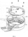
FIG. 2 is an exploded view of a connection mechanism of a head-mounted display provided by an exemplary embodiment of the present disclosure. -
FIG. 3 is an assembled view of a first rotation member and a second rotation member inFIG. 2 . -
FIG. 4 is a partial enlarged view of a gear structure assembled inFIG. 3 . -
FIG. 5 is a schematic view of a second rotation member inFIG. 2 . -
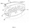
FIG. 6 is a schematic view showing the connection between a head-mounted bracket and a cover provided by another embodiment. - To better understand purposes, technical solutions, and advantages of the present disclosure, the following will further illustrate the present disclosure in combination with various embodiments and the accompanying drawings. It should be understood that the specific embodiments described herein are merely used to illustrate the present disclosure, and are not a limitation of the present disclosure.
- In the description of the present disclosure, the "first", "second" are merely used for description, and cannot be understood to indicate or imply relative importance or implicitly indicate the number of the indicated technical features. Therefore, features with a limitation of "first" or "second" can explicitly or implicitly include one or more feature. In the description of the present disclosure, the term "a plurality of" means two or more than two, unless there is specific limitation.
- In the description of the present disclosure, it should be noted that, unless explicitly stated or limited, the terms "mount", "connected" and "connection" should be broadly understood, for example, it may be a fixed connection, or may be a detachable connection, or integral connection; it may be a mechanical connection, or may be an electrical connection, or may be communication with each other; it may be directly connected, or may be indirectly connected via intermediary, or may be communication between interiors of two elements or interactions between two elements. Those skilled in the art can understand the specific definition of above terms in the present disclosure according to specific conditions.
- The following disclosure provides many different embodiments or examples, for realize different structures of the present disclosure. In order to simplify the present disclosure, the following will describe components and setting of specific examples. Certainly, thereby are just examples, and are not intended to limit the present disclosure. Furthermore, in the present disclosure, reference numerals and/or reference letters may be repeated in different embodiments. This repetition is for the purpose of simplicity and clarity, and does not indicate relationships among various embodiments and/or settings discussed herein.
- Referring to
FIG. 1 , a head-mounted display is provided in an embodiment of the present disclosure. The head-mounted display includes adisplay device 20, aheadphone device 30, a head-mountedbracket 40, and aconnection mechanism 50. Thedisplay device 20 includes adisplay body 21 with a displayingside 21A and supportarms 22. Thedisplay side 21A is configured to project images to user eyes. Thesupport arms 22 extend from two ends of thedisplay body 21 in a direction A toward the displayingside 21A, which forms a shape similar to the shape of a pair of glasses. Theheadphone device 30 includes twoheadphone bodies 31 for outputting audio signals. The head-mountedbracket 40 includes a head-mountedportion 41 andconnection portions 42 extending from two ends of the head-mountedportion 41. Each of twoconnection mechanisms 50 respectively connects one of thesupport arms 22 at two ends of thedisplay body 21 to onecorresponding headphone body 31 and onecorresponding connection portion 42. Referring toFIGs. 2-4 , eachconnection mechanism 50 includes afirst rotation member 51 and asecond rotation member 52. Thefirst rotation member 51 connects onesupport arm 22 to thecorresponding headphone body 31. Thesecond rotation member 52 rotatably connects to thefirst rotation member 51, and further connects to thecorresponding connection portion 42. - The above embodiment of the present disclosure provides a head-mounted display including the
connection mechanism 50. Theconnection mechanism 50 can connect thedisplay device 20, theheadphone device 30, and the head-mountedbracket 40. Theconnection mechanism 50 includes thefirst rotation member 51 for connecting thesupport arm 22 at one end to onecorresponding headphone body 31, and thesecond rotation member 52 rotatably connecting to thefirst rotation member 51, and thesecond rotation member 52 further connects to theconnection portion 42 at one end of the head-mountedbracket 40. Thedisplay device 20 and the head-mountedbracket 40 are driven to rotate relative to each other when thefirst rotation member 51 rotates relative around thesecond rotation member 52, which provides a flexible connection manner, thus thedisplay device 20 and the head-mountedbracket 40 can be folded together to carry around, which enhances portability of the product. - In the embodiment, at least one of the two
connection mechanisms 50 includes agear structure 53. Thegear structure 53 includes a tooth-shaped structure 532. The tooth-shaped structure 532 is arranged at acircumferential wall 531 of thefirst rotation member 51 or that of thesecond member 52, and aresilient sheet 533 fixes to another one of thefirst rotation member 51 and thesecond rotation member 52 and engages with the tooth-shaped structure 532. Thefirst rotation member 51 and thesecond rotation member 52 rotatably engage with each other through the tooth-shaped structure 532 and theresilient sheet 533 under an external force. With the engagement between the tooth-shaped structure 532 and theresilient sheet 533, the head-mountedbracket 40 keeps a relative angle with thedisplay device 20. Theresilient sheet 533 is deformed by an external force and slides relative to the tooth-shaped structure 532, which enables thedisplay device 20 to rotate around an axis extending through the axle centers of the twoheadphone bodies 31. It should be noted that, only one of theconnection mechanisms 50 supporting thegear structure 53, or both of the twoconnection mechanisms 50 supporting thegear structures 53, which ensure that the head-mountedbracket 40 keep a relative angle with thedisplay device 20. - In some cases, when both of the two
connection mechanisms 50 include thegear structures 53, if the user exert an improper force, for example, when thedisplay device 20 and the head-mountedbracket 40 are pulled toward one of theconnection mechanisms 50, the force applied to theother gear structure 53 is relatively small and then the rotations of the twogear structures 53 are not consistent. Thus the device may be broke down easily. This problem can be solved with only one of theconnection mechanisms 50 with thegear structure 53, and thegear structure 53 set in only one of theconnection mechanisms 50 drives theother connection mechanism 50 to rotate together with the one of theconnection mechanisms 50. - The above embodiment of the present disclosure includes the
connection mechanism 50 for connecting thedisplay device 20, theheadphone device 30, and the head-mountedbracket 40. Theconnection mechanism 50 includes thegear structure 53 with the tooth-shaped structure 532 and theresilient sheet 533. Under an external fore, theconnection mechanism 50 drives thedisplay device 20 to rotate relative to the head-mountedbracket 40 by virtue of the rotation of the tooth-shapedstructure 532 and the engagedresilient sheet 533, which provides a flexible connection manner to allow thedisplay device 20 to be folded together with the head-mountedbracket 40, to enhance the portability of the product. - Specifically, the
first rotation member 51 includes a latchingside 51A with a latching structure 54, and anopposite side 51B opposite to the latchingside 51A. Thesecond rotation member 52 includes a latchingside 52A also with a latching structure 54 and anopposite side 52B opposite to the latchingside 52A. Thegear structure 53 is arranged at the latchingsides first rotation member 51 and thesecond rotation member 52 is an annular frame, and includes an innercircumferential wall circumferential wall first rotation member 51 is larger or smaller than that of thesecond rotation member 52. Furthermore, one of thefirst rotation member 51 and thesecond rotation member 52, with a larger radius, includes the latching structure 54. The latching structure 54 includes a firstjoint portion 541 extending from the latchingside joint portion 542 extending from the firstjoint portion 541 in a direction opposite to theopposite side joint portion 542 can provide with thecircumferential wall 531 and the tooth-shapedstructure 532 of thegear structure 53. Another one of thefirst rotation member 51 and thesecond rotation member 52, with a smaller radius, includes the latching structure 54 with a thirdjoint portion 543. The thirdjoint portion 543 extends from the latchingside joint portion 541 fits with the thirdjoint portion 543. Thus, the thirdjoint portion 543 on thefirst rotation member 51 or thesecond rotation member 52 with a smaller annulus radius, can be pressed to connect with the firstjoint portion 543 through the inner of another one of thefirst rotation member 51 or thesecond rotation member 52 with a greater annulus radius, and theopposite side member 51 or thesecond rotation member 52 with the greater annulus radius, which enables thefirst rotation member 51 to rotatably engage with thesecond rotation member 52. The structure of anotherconnection mechanism 50 is almost the same as the above, the difference between the twoconnection mechanisms 50 is that theresilient sheet 533 is not arranged in the anotherconnection mechanism 50, or neither the mentionedresilient sheet 533 nor the tooth-shapedstructure 532 are not arranged in the anotherconnection mechanism 50. - For purpose of illustrating the above principle, the following in combination with an embodiment is for specifically illustration. In the embodiment, the radius of the annulus of the
first rotation member 51 is greater than that of thesecond rotation member 52. However, the present disclosure is not limited thereto. - The second
joint portion 542 of thefirst rotation member 51 is a concentric annular ring extending from the annular frame, and includes an innercircumferential wall 542a and an outercircumferential wall 542b. In the embodiment, thecircumferential wall 531 and the tooth-shapedstructure 532 of thegear structure 53 are arranged at the secondjoint portion 543. Specifically, the tooth-shapedstructure 532 is arranged at the innercircumferential wall 542a of the concentric annular ring. It should be understood that the innercircumferential wall 542a of the concentric annular ring can act as thecircumferential wall 531 of thegear structure 53. Theresilient sheet 533 of thegear structure 53 is fixed to thesecond rotation member 52. When the thirdjoint portion 543 of thesecond rotation member 52 is pressed to connect with the firstjoint portion 541 by the inner portion of thefirst rotation member 51, theresilient sheet 533 engages with the tooth-shapedstructure 532 correspondingly. - Specifically, in the embodiment, a resilient
sheet fixing portion 521 is arranged at the annular frame of thesecond rotation member 52. The resilientsheet fixing portion 521 is located at a position corresponding to the tooth-shapedstructure 532 when thesecond rotation member 52 engages with thefirst rotation member 51. Specifically, in the embodiment, the resilientsheet fixing portion 521 is a limiting through hole with a shape corresponding to the shape of theresilient sheet 533. Part of theresilient sheet 533 is limited and fixed to the inner side of thesecond rotation member 52. Part of theresilient sheet 533 for engagement extends out through the limiting through hole and corresponds to the tooth-shapedstructure 532. Preferably, in the embodiment, two resilientsheet fixing portions 521 are provided. Theresilient sheet 533 includes two portions which extend outside the fixingportions 521 and engage with the tooth-shapedstructure 532. When one of the two portions is located in a gap between two adjacent teeth of the tooth-shapedstructure 532, another portion stands against the tooth of the tooth-shapedstructure 532. Therefore, the accuracy of a rotation location can achieve to a half of the teeth pitch of the tooth-shapedstructure 532. - In a preferred embodiment of the present disclosure, the
first rotation member 51 and thesecond rotation member 52 utilize annular frames and connect to each other by utilizing the latching structure 54, thus to form an accommodating chamber by the annular frame. The accommodating chamber can accommodate electric components, such as PCB, batteries, or the like, which avoids the head-mounted display supplying a redundant structure for allocating additional accommodate space. Preferably, an outer cover with a latching structure can be arranged at the outer side of the accommodating chamber formed by the annular frames, which can be easily disassembled. Thus the components are allowed to be replaced, maintained, repaired, or the like easily. - However, as long as that the
resilient sheet 533 is rotatable relative to the tooth-shapedstructure 532 and keeps engaging with the tooth-shapedstructure 532, thefirst rotation member 51 and thesecond rotation member 52 in the present disclosure are not limited to the annular frames. For example, one of thefirst rotation member 51 and thesecond rotation ember 52 provides the tooth-shapedstructure 532 and is a frame with an outer rectangle wall and an inner circular wall, and the tooth-shaped structure is mounted to the inner circular wall. Accordingly, another of thefirst rotation member 51 and thesecond rotation member 52 can be an embedded annular frame of the above embodiment, and can be a circular solid embedded in the circular cavity formed by the circular wall of the one of thefirst rotation member 51 and the second rotation member which provides the tooth-shapedstructure 532, and theresilient sheet 533 is arranged at the circular outer wall of the circular solid and engages the tooth-shapedstructure 532 correspondingly. It should be understood that, one of thefirst rotation member 51 and thesecond rotation member 52 which provides the tooth-shapedstructure 532 may be an annular frame with a smaller radius, with the tooth-shapedstructure 532 arranged at the outer circumferential wall of the annular frame. Another of thefirst rotation member 51 and thesecond rotation member 52 which provides theresilient sheet 533 can be of any shape with an inner circumferential wall corresponding to the outer circumferential wall of the one of thefirst rotation member 51 and thesecond rotation member 52, which enables the tooth-shapedstructure 532 to be embedded in the inner circumferential wall. Theresilient sheet 533 engages with the tooth-shapedstructure 532 of the embedded one of thefirst rotation member 51 and thesecond rotation member 52 which provides the tooth-shapedstructure 532 through the inner circumferential wall. An ordinary person skilled in the art constructs the relative engagement rotation of the first rotation member and the second rotation member according to the principles of the present disclosure should be included in the scope of the present disclosure. - In the embodiment, the
opposite side 51B of thefirst rotation member 51 connects to thecorresponding headphone body 31. Specifically, theheadphone body 31 connects to thefirst rotation member 51 by the fixingmember 80. The fixingmember 80 fixedly connects to theopposite side 51B of thefirst rotation member 51, and theheadphone body 31 is fixed to the fixingmember 80. The specific fixing manner can be riveted joint, and also can be any fixing manner provided by the art. - Preferably, the head-mounted display 10 further includes a
touch panel 60. Thetouch panel 60 is arranged at theopposite side 52B of thesecond rotation member 52. Specifically, referring toFIG. 6 , the head-mounted display 10 may further include acover 70. Thecover 70 includes an openingportion 71 and a fixingportion 72. Thetouch panel 60 is fixed to thecover 70 and is exposed through the openingportion 71. The fixingportion 72 fixedly connects to thesecond rotation member 52. Specifically, as another embodiment of the head-mountedbracket 40 and theconnection mechanism 50 shown inFIG. 5 , thesecond rotation member 52 includes a fixedconnection portion 525. Specifically, the fixedconnection portion 525 is a rivet fixing hole, and the fixedconnection portion 525 fixedly connects to the fixingportion 72 of the cover by rivets. In this embodiment, the connection end 42 of the head-mountedbracket 40 pivotally connects to thecover 70 via apivot 421. Thecover 70 includes apivot hole 73, which enables thepivot 421 of theconnection end 42 to extend through thepivot hole 73 to be fixed in thecover 70. - In another embodiment, when there is no
cover 70, the connection end 42 of thehead bracket 40 pivotally connects to thesecond rotation member 52 via a pivot. Specifically, referring toFIG. 6 , thesecond rotation member 52 includes apivot hole 522, which enables thepivot 421 of theconnection end 42 to extend through thepivot hole 522 from the outer side of thesecond rotation member 52, and the connection end is further fixed to the inner side of thesecond rotation member 52 by asleeve 523. - However, the connection manner between the connection end 42 of the head-mounted
bracket 40 and theconnection mechanism 50 is not limited to the above specific embodiment. Referring toFIG. 1 , the connection end 42 of the head-mountedbracket 40 can be integrally fixedly formed in thesecond rotation member 52 or thecover 70, and it can also connects to thesecond rotation member 52 or thecover 70 by an inserting manner, latching manner, or the like. - In the above preferable embodiment, the head-mounted display achieves rotatable connection by virtue of the latching structures 54 of the
first rotation member 51 and thesecond rotation member 52 of theconnection mechanism 50. The head-mountedbracket 40 connects to thesecond rotation member 52, thesupport arms 22 of thedisplay device 20 connect to thefirst rotation member 51, which enables thedisplay device 20 and the head-mountedbracket 40 to rotate relative to each other under rotation of thefirst rotation member 51 and thesecond rotation member 52. The connection includes a direct connection, or an indirect connection via other component. - In the above embodiment, the
gear structure 53 enables thefirst rotation member 51 and thesecond rotation member 52 to rotate relative to each other under damping, which can position the relative included angle between the head-mountedportion 41 and thedisplay body 21. It could be understood that structures which achieves the above function is not limited to thegear structure 53 of the present disclosure. For example, the structures may be two rubbers, as long as damping structures which cause thefirst rotation member 51 and thesecond rotation member 52 to rotate relative to each other under damping. - The foregoing description is only the preferred embodiments of the present disclosure, but is not intended to limit the scope of the invention. Accordingly, any modification, alternatives, improvements or the like within the spirit and principles of the present disclosure should be included in the scope of the present disclosure.
Claims (14)
- A head-mounted display, comprising:a display device comprising one display body and two support arms extending from two opposite ends of the display body respectively;a headphone device comprising two headphone bodies for outputting an audio signal;a head-mounted bracket comprising a head-mounted portion and two connection portions extending from two ends of the head-mounted portion respectively; andtwo connection mechanisms connecting each support arm to one corresponding headphone body and one corresponding connection portion, wherein each connection mechanism comprises a first rotation member and a second rotation member, the first rotation member connects each support arm and the corresponding headphone body, the second rotation member rotatably connects the first rotation member to the corresponding connection portion.
- The head-mounted display according to claim 1, wherein at least one of the two connection mechanisms comprises a damping structure making the first rotation member and the second rotation member to rotate relative to each other under damping.
- The head-mounted display according to claim 2, wherein the damping structure is a gear structure comprising: one of the first rotation member and the second rotation member comprises a circumferential wall with a tooth-shaped structure, and another one of the first rotation member and the second rotation member comprises a resilient sheet engaging with the tooth-shaped structure, and the first rotation member and the second rotation member rotate by engaging the tooth-shaped structure with the resilient sheet under an external force.
- The head-mounted display according to claim 3, wherein each of the first rotation member and the second rotation member comprises a latching side with a latching structure and an opposite side opposite to the latching side; the gear structure is arranged at the latching side.
- The head-mounted display according to claim 4, wherein each of the first rotation member and the second rotation member is an annular frame comprising an inner circumferential wall and an outer circumferential wall, an annulus radius of the first rotation member is greater than or smaller than that of the second rotation member.
- The head-mounted display according to claim 5, wherein the latching structure on one of the first rotation member and the second rotation member with a greater annulus radius comprises a first joint portion extending from the latching side toward a center of the annulus, and a second joint portion extending from the first joint portion to a direction opposite to the opposite side, and the latching structure on the other one of the first rotation member and the second rotation member with a smaller annulus comprises a third joint portion extending from the latching side to a direction opposite to the center of the annulus, the first joint portion attaches to the third joint portion.
- The head-mounted display according to claim 6, wherein the radius of the annulus of the first rotation member is greater than that of the second rotation member.
- The head-mounted display according to claim 7, wherein the second joint portion of the first rotation member comprises a concentric annular ring extending from the annular frame, the concentric annular ring comprises an inner circumferential wall and an outer circumferential wall; the tooth-shaped structure is arranged on the inner circumferential wall of the concentric annular ring; the resilient sheet is fixed to the second rotation member, and the resilient sheet engages with the tooth-shaped structure in position when the third joint portion of the second rotation member is pressed to connect with the first joint portion by an interior side of the first rotation member.
- The head-mounted display according to claim 3, wherein the another one of the first rotation member and the second rotation member comprising the resilient sheet further comprises two resilient sheet fixing portions, the resilient sheet comprises two portions extending outside the resilient sheet fixing portions and engaging with the tooth-shaped structure, and one of the two portions is located at a gap between two adjacent teeth of the tooth-shaped structure, another portion is pressed to connect with a tooth of the tooth-shaped structure.
- The head-mounted display according to claim 4, wherein the headphone body connects to the opposite side of the first rotation member.
- The head-mounted display according to claim 4, further comprising a touch panel, wherein the touch panel is arranged on the opposite side of the second rotation member.
- The head-mounted display according to claim 11, further comprising a cover, wherein the cover comprises an opening portion and a fixing portion, the touch panel is fixed to the cover and exposed through the opening portion; the fixing portion fixedly connects to the second rotation member.
- The head-mounted display according to claim 12, wherein a connection end of the head-mounted bracket rotatably connects to the cover via a pivot.
- The head-mounted display according to claim 1, wherein a connection end of the head-mounted bracket rotatably connects to the second rotation member via a pivot.
Applications Claiming Priority (1)
| Application Number | Priority Date | Filing Date | Title |
|---|---|---|---|
| PCT/CN2015/089564 WO2017045110A1 (en) | 2015-09-14 | 2015-09-14 | Head mounted display apparatus |
Publications (3)
| Publication Number | Publication Date |
|---|---|
| EP3351995A1 true EP3351995A1 (en) | 2018-07-25 |
| EP3351995A4 EP3351995A4 (en) | 2019-05-22 |
| EP3351995B1 EP3351995B1 (en) | 2020-11-04 |
Family
ID=56987312
Family Applications (1)
| Application Number | Title | Priority Date | Filing Date |
|---|---|---|---|
| EP15903801.7A Not-in-force EP3351995B1 (en) | 2015-09-14 | 2015-09-14 | Head mounted display apparatus |
Country Status (4)
| Country | Link |
|---|---|
| US (1) | US9864200B2 (en) |
| EP (1) | EP3351995B1 (en) |
| CN (1) | CN105829949B (en) |
| WO (1) | WO2017045110A1 (en) |
Cited By (1)
| Publication number | Priority date | Publication date | Assignee | Title |
|---|---|---|---|---|
| WO2025044024A1 (en) * | 2023-08-31 | 2025-03-06 | 歌尔科技有限公司 | Headset |
Families Citing this family (23)
| Publication number | Priority date | Publication date | Assignee | Title |
|---|---|---|---|---|
| EP3339933A4 (en) | 2015-08-19 | 2019-07-17 | Shenzhen Royole Technologies Co. Ltd. | Wearable display device |
| KR102003629B1 (en) | 2015-08-19 | 2019-07-24 | 선전 로욜 테크놀로지스 컴퍼니 리미티드 | Head mounted electronic device |
| EP3370101A4 (en) | 2015-08-19 | 2019-04-24 | Shenzhen Royole Technologies Co., Ltd. | Head-mounted electronic device |
| WO2017028281A1 (en) | 2015-08-19 | 2017-02-23 | 深圳市柔宇科技有限公司 | Head-mounted electronic device |
| EP3351995B1 (en) * | 2015-09-14 | 2020-11-04 | Shenzhen Royole Technologies Co., Ltd | Head mounted display apparatus |
| CN107407809B (en) * | 2016-01-26 | 2020-04-14 | 深圳市柔宇科技有限公司 | Head-mounted device, earphone device, and head-mounted device separation control method |
| USD817327S1 (en) * | 2016-09-14 | 2018-05-08 | Shenzhen Royole Technologies Co. Ltd. | Head mounted display device |
| CN106773043B (en) * | 2016-12-21 | 2023-08-25 | 歌尔科技有限公司 | A strap connecting hinge and head-mounted device |
| CN107561711B (en) * | 2017-09-30 | 2023-11-10 | 歌尔科技有限公司 | VR head-mounted device |
| WO2019090458A1 (en) * | 2017-11-07 | 2019-05-16 | 深圳市柔宇科技有限公司 | Head-mounted display device |
| US10656670B2 (en) | 2018-06-04 | 2020-05-19 | Htc Corporation | Head-mounted display device |
| CN108873335B (en) * | 2018-06-06 | 2022-05-10 | 歌尔智能科技有限公司 | Augmented reality headset |
| CN109090755B (en) * | 2018-08-30 | 2024-05-28 | 歌尔科技有限公司 | Wearing device and head-mounted equipment with same |
| USD934197S1 (en) * | 2019-03-24 | 2021-10-26 | Buddy Snow | Headphones |
| USD940684S1 (en) * | 2019-03-24 | 2022-01-11 | Buddy Snow | Earphones |
| CN110430505B (en) * | 2019-08-19 | 2024-04-09 | 广东得胜电子有限公司 | Earphone rotating shaft mechanism capable of rotating, locking and positioning |
| CN115220232A (en) * | 2019-12-06 | 2022-10-21 | Oppo广东移动通信有限公司 | Protective shell and head-mounted equipment |
| JP7643040B2 (en) * | 2020-12-28 | 2025-03-11 | カシオ計算機株式会社 | Speaker device and hood-type speaker device |
| CN113464824B (en) * | 2021-06-30 | 2023-09-05 | 亮风台(上海)信息科技有限公司 | connecting device |
| CN113456088B (en) * | 2021-08-04 | 2024-10-15 | 滇西应用技术大学珠宝学院 | Electroencephalogram acquisition device and method for hyperkinetic syndrome children |
| CN114675423B (en) * | 2022-04-12 | 2024-11-29 | 闪耀现实(无锡)科技有限公司 | Head-mounted display device |
| USD1112155S1 (en) * | 2024-01-05 | 2026-02-10 | Cognito Therapeutics, Inc. | Headset with detachable headband |
| USD1107682S1 (en) * | 2024-01-05 | 2025-12-30 | Cognito Therapeutics, Inc. | Headset with detachable headband |
Family Cites Families (30)
| Publication number | Priority date | Publication date | Assignee | Title |
|---|---|---|---|---|
| GB2247820B (en) * | 1990-08-24 | 1994-09-28 | Ind Ltd W | Headset |
| US6369952B1 (en) * | 1995-07-14 | 2002-04-09 | I-O Display Systems Llc | Head-mounted personal visual display apparatus with image generator and holder |
| US20040201695A1 (en) * | 2001-02-15 | 2004-10-14 | Rei Inasaka | System for delivering news |
| JP2007243631A (en) * | 2006-03-09 | 2007-09-20 | Nikon Corp | Head mounted display device |
| WO2007119351A1 (en) * | 2006-03-15 | 2007-10-25 | Nikon Corporation | Head-mount display |
| CN101705763B (en) * | 2009-10-26 | 2011-12-14 | 宁波永发集团有限公司 | Electronic coded lock panel |
| CN102918443B (en) * | 2010-04-27 | 2016-01-13 | 寇平公司 | wearable electronic display |
| CN202026447U (en) * | 2011-03-24 | 2011-11-02 | 旭丽电子(广州)有限公司 | Bluetooth headset |
| TW201419883A (en) * | 2012-11-12 | 2014-05-16 | Powertech Ind Co Ltd | Headphone device |
| US20160004082A1 (en) * | 2013-02-12 | 2016-01-07 | Virtual Goggles Inc. | Headset with Binary Display and Integrated Computing System |
| JP2014178960A (en) * | 2013-03-15 | 2014-09-25 | Sony Corp | Acceleration sensation presentation device, acceleration sensation presentation method, and acceleration sensation presentation system |
| US10137361B2 (en) * | 2013-06-07 | 2018-11-27 | Sony Interactive Entertainment America Llc | Systems and methods for using reduced hops to generate an augmented virtual reality scene within a head mounted system |
| US10905943B2 (en) * | 2013-06-07 | 2021-02-02 | Sony Interactive Entertainment LLC | Systems and methods for reducing hops associated with a head mounted system |
| CN104280881B (en) * | 2013-07-09 | 2021-03-23 | 杭州美盛红外光电技术有限公司 | Portable imaging device |
| CN103596099A (en) * | 2013-12-03 | 2014-02-19 | 全南三扬电子有限公司 | Rotary earphone |
| CN104166239A (en) * | 2014-08-25 | 2014-11-26 | 成都贝思达光电科技有限公司 | Head-worn video glasses view-finding device for high definition camera |
| CN204229050U (en) * | 2014-12-03 | 2015-03-25 | 成都贝思达光电科技有限公司 | A kind of portable turning video eyeglasses |
| CN104503086A (en) * | 2014-12-31 | 2015-04-08 | 青岛歌尔声学科技有限公司 | Adjustable head-mounted display |
| CN104503585A (en) * | 2014-12-31 | 2015-04-08 | 青岛歌尔声学科技有限公司 | Touch type head-mounted display |
| CN204302573U (en) * | 2014-12-31 | 2015-04-29 | 青岛歌尔声学科技有限公司 | A kind of head-mounted display |
| US9635450B2 (en) * | 2015-02-20 | 2017-04-25 | Oculus Vr, Llc | Audio headphones for virtual reality head-mounted display |
| CN204575970U (en) * | 2015-03-18 | 2015-08-19 | 青岛歌尔声学科技有限公司 | A kind of head-mounted display |
| CN204666953U (en) * | 2015-04-01 | 2015-09-23 | 深圳市柔宇科技有限公司 | A kind of head-mounted display apparatus |
| EP3280153B1 (en) * | 2015-04-03 | 2020-03-11 | Shenzhen Royole Technologies Co., Ltd | Head-mounted electronic device |
| JP2018518100A (en) * | 2015-05-29 | 2018-07-05 | シェンツェン ロイヤル テクノロージーズ シーオー.,エルティーディー.Shenzhen Royole Technologies Co.,Ltd. | Display module and electronic device including the display module |
| WO2017028281A1 (en) * | 2015-08-19 | 2017-02-23 | 深圳市柔宇科技有限公司 | Head-mounted electronic device |
| EP3339933A4 (en) * | 2015-08-19 | 2019-07-17 | Shenzhen Royole Technologies Co. Ltd. | Wearable display device |
| EP3370101A4 (en) * | 2015-08-19 | 2019-04-24 | Shenzhen Royole Technologies Co., Ltd. | Head-mounted electronic device |
| EP3351995B1 (en) * | 2015-09-14 | 2020-11-04 | Shenzhen Royole Technologies Co., Ltd | Head mounted display apparatus |
| KR102060233B1 (en) * | 2015-09-27 | 2019-12-27 | 선전 로욜 테크놀로지스 컴퍼니 리미티드 | Head mounted display |
-
2015
- 2015-09-14 EP EP15903801.7A patent/EP3351995B1/en not_active Not-in-force
- 2015-09-14 WO PCT/CN2015/089564 patent/WO2017045110A1/en not_active Ceased
- 2015-09-14 CN CN201580002987.3A patent/CN105829949B/en not_active Expired - Fee Related
-
2016
- 2016-03-02 US US15/059,111 patent/US9864200B2/en not_active Expired - Fee Related
Cited By (1)
| Publication number | Priority date | Publication date | Assignee | Title |
|---|---|---|---|---|
| WO2025044024A1 (en) * | 2023-08-31 | 2025-03-06 | 歌尔科技有限公司 | Headset |
Also Published As
| Publication number | Publication date |
|---|---|
| US9864200B2 (en) | 2018-01-09 |
| CN105829949B (en) | 2018-06-12 |
| WO2017045110A1 (en) | 2017-03-23 |
| US20170075121A1 (en) | 2017-03-16 |
| EP3351995B1 (en) | 2020-11-04 |
| CN105829949A (en) | 2016-08-03 |
| EP3351995A4 (en) | 2019-05-22 |
Similar Documents
| Publication | Publication Date | Title |
|---|---|---|
| EP3351995B1 (en) | Head mounted display apparatus | |
| CN204666953U (en) | A kind of head-mounted display apparatus | |
| CN107533222B (en) | Head-mounted electronic device | |
| JP7012745B2 (en) | Joint parts for head-mounted displays | |
| CN107003515B (en) | Head mounted electronic device | |
| US10042168B2 (en) | Head-mounted electronic device | |
| KR101999198B1 (en) | Wearable electronic device | |
| JP2018517316A (en) | Modularized head mounted display device and removable module | |
| EP3339933A1 (en) | Wearable display device | |
| JP7437819B2 (en) | display device | |
| CN107820579A (en) | Wear-type electronic equipment and its display module | |
| JP2016102543A (en) | Elevation angle adjustment mechanism, rotation angle adjustment mechanism, and electronic apparatus | |
| CN107850776A (en) | Wearable electronic installation | |
| JP2016102542A (en) | Electronic apparatus | |
| JP2007243631A (en) | Head mounted display device | |
| CN106416294B (en) | Wearable Electronic Devices | |
| JP4904976B2 (en) | Headphone and head mounted display | |
| JP2016102541A (en) | Electronic apparatus | |
| JP2013218181A (en) | Support and projection system | |
| JP2008271054A (en) | Body-mounted display | |
| CN115903238A (en) | Head shows mechanism and head mounted device | |
| JP2008147744A (en) | Output device | |
| JP2016053658A (en) | Imaging apparatus | |
| CN106031194A (en) | Wearable electronic apparatus | |
| JP2007251308A (en) | Head mounted display |
Legal Events
| Date | Code | Title | Description |
|---|---|---|---|
| STAA | Information on the status of an ep patent application or granted ep patent |
Free format text: STATUS: THE INTERNATIONAL PUBLICATION HAS BEEN MADE |
|
| PUAI | Public reference made under article 153(3) epc to a published international application that has entered the european phase |
Free format text: ORIGINAL CODE: 0009012 |
|
| STAA | Information on the status of an ep patent application or granted ep patent |
Free format text: STATUS: REQUEST FOR EXAMINATION WAS MADE |
|
| 17P | Request for examination filed |
Effective date: 20171122 |
|
| AK | Designated contracting states |
Kind code of ref document: A1 Designated state(s): AL AT BE BG CH CY CZ DE DK EE ES FI FR GB GR HR HU IE IS IT LI LT LU LV MC MK MT NL NO PL PT RO RS SE SI SK SM TR |
|
| AX | Request for extension of the european patent |
Extension state: BA ME |
|
| DAV | Request for validation of the european patent (deleted) | ||
| DAX | Request for extension of the european patent (deleted) | ||
| A4 | Supplementary search report drawn up and despatched |
Effective date: 20190424 |
|
| RIC1 | Information provided on ipc code assigned before grant |
Ipc: G02B 27/01 20060101ALN20190416BHEP Ipc: G02B 27/02 20060101AFI20190416BHEP |
|
| GRAP | Despatch of communication of intention to grant a patent |
Free format text: ORIGINAL CODE: EPIDOSNIGR1 |
|
| STAA | Information on the status of an ep patent application or granted ep patent |
Free format text: STATUS: GRANT OF PATENT IS INTENDED |
|
| RIC1 | Information provided on ipc code assigned before grant |
Ipc: G02B 27/02 20060101AFI20200402BHEP Ipc: G02B 27/01 20060101ALN20200402BHEP |
|
| INTG | Intention to grant announced |
Effective date: 20200506 |
|
| GRAS | Grant fee paid |
Free format text: ORIGINAL CODE: EPIDOSNIGR3 |
|
| GRAA | (expected) grant |
Free format text: ORIGINAL CODE: 0009210 |
|
| STAA | Information on the status of an ep patent application or granted ep patent |
Free format text: STATUS: THE PATENT HAS BEEN GRANTED |
|
| AK | Designated contracting states |
Kind code of ref document: B1 Designated state(s): AL AT BE BG CH CY CZ DE DK EE ES FI FR GB GR HR HU IE IS IT LI LT LU LV MC MK MT NL NO PL PT RO RS SE SI SK SM TR |
|
| REG | Reference to a national code |
Ref country code: GB Ref legal event code: FG4D |
|
| REG | Reference to a national code |
Ref country code: CH Ref legal event code: EP |
|
| REG | Reference to a national code |
Ref country code: AT Ref legal event code: REF Ref document number: 1331568 Country of ref document: AT Kind code of ref document: T Effective date: 20201115 |
|
| REG | Reference to a national code |
Ref country code: IE Ref legal event code: FG4D |
|
| REG | Reference to a national code |
Ref country code: DE Ref legal event code: R096 Ref document number: 602015061718 Country of ref document: DE |
|
| REG | Reference to a national code |
Ref country code: NL Ref legal event code: MP Effective date: 20201104 |
|
| REG | Reference to a national code |
Ref country code: AT Ref legal event code: MK05 Ref document number: 1331568 Country of ref document: AT Kind code of ref document: T Effective date: 20201104 |
|
| PG25 | Lapsed in a contracting state [announced via postgrant information from national office to epo] |
Ref country code: NO Free format text: LAPSE BECAUSE OF FAILURE TO SUBMIT A TRANSLATION OF THE DESCRIPTION OR TO PAY THE FEE WITHIN THE PRESCRIBED TIME-LIMIT Effective date: 20210204 Ref country code: PT Free format text: LAPSE BECAUSE OF FAILURE TO SUBMIT A TRANSLATION OF THE DESCRIPTION OR TO PAY THE FEE WITHIN THE PRESCRIBED TIME-LIMIT Effective date: 20210304 Ref country code: RS Free format text: LAPSE BECAUSE OF FAILURE TO SUBMIT A TRANSLATION OF THE DESCRIPTION OR TO PAY THE FEE WITHIN THE PRESCRIBED TIME-LIMIT Effective date: 20201104 Ref country code: FI Free format text: LAPSE BECAUSE OF FAILURE TO SUBMIT A TRANSLATION OF THE DESCRIPTION OR TO PAY THE FEE WITHIN THE PRESCRIBED TIME-LIMIT Effective date: 20201104 Ref country code: GR Free format text: LAPSE BECAUSE OF FAILURE TO SUBMIT A TRANSLATION OF THE DESCRIPTION OR TO PAY THE FEE WITHIN THE PRESCRIBED TIME-LIMIT Effective date: 20210205 |
|
| PG25 | Lapsed in a contracting state [announced via postgrant information from national office to epo] |
Ref country code: BG Free format text: LAPSE BECAUSE OF FAILURE TO SUBMIT A TRANSLATION OF THE DESCRIPTION OR TO PAY THE FEE WITHIN THE PRESCRIBED TIME-LIMIT Effective date: 20210204 Ref country code: LV Free format text: LAPSE BECAUSE OF FAILURE TO SUBMIT A TRANSLATION OF THE DESCRIPTION OR TO PAY THE FEE WITHIN THE PRESCRIBED TIME-LIMIT Effective date: 20201104 Ref country code: SE Free format text: LAPSE BECAUSE OF FAILURE TO SUBMIT A TRANSLATION OF THE DESCRIPTION OR TO PAY THE FEE WITHIN THE PRESCRIBED TIME-LIMIT Effective date: 20201104 Ref country code: PL Free format text: LAPSE BECAUSE OF FAILURE TO SUBMIT A TRANSLATION OF THE DESCRIPTION OR TO PAY THE FEE WITHIN THE PRESCRIBED TIME-LIMIT Effective date: 20201104 Ref country code: IS Free format text: LAPSE BECAUSE OF FAILURE TO SUBMIT A TRANSLATION OF THE DESCRIPTION OR TO PAY THE FEE WITHIN THE PRESCRIBED TIME-LIMIT Effective date: 20210304 Ref country code: ES Free format text: LAPSE BECAUSE OF FAILURE TO SUBMIT A TRANSLATION OF THE DESCRIPTION OR TO PAY THE FEE WITHIN THE PRESCRIBED TIME-LIMIT Effective date: 20201104 Ref country code: AT Free format text: LAPSE BECAUSE OF FAILURE TO SUBMIT A TRANSLATION OF THE DESCRIPTION OR TO PAY THE FEE WITHIN THE PRESCRIBED TIME-LIMIT Effective date: 20201104 |
|
| REG | Reference to a national code |
Ref country code: LT Ref legal event code: MG9D |
|
| PG25 | Lapsed in a contracting state [announced via postgrant information from national office to epo] |
Ref country code: HR Free format text: LAPSE BECAUSE OF FAILURE TO SUBMIT A TRANSLATION OF THE DESCRIPTION OR TO PAY THE FEE WITHIN THE PRESCRIBED TIME-LIMIT Effective date: 20201104 |
|
| PG25 | Lapsed in a contracting state [announced via postgrant information from national office to epo] |
Ref country code: SM Free format text: LAPSE BECAUSE OF FAILURE TO SUBMIT A TRANSLATION OF THE DESCRIPTION OR TO PAY THE FEE WITHIN THE PRESCRIBED TIME-LIMIT Effective date: 20201104 Ref country code: LT Free format text: LAPSE BECAUSE OF FAILURE TO SUBMIT A TRANSLATION OF THE DESCRIPTION OR TO PAY THE FEE WITHIN THE PRESCRIBED TIME-LIMIT Effective date: 20201104 Ref country code: CZ Free format text: LAPSE BECAUSE OF FAILURE TO SUBMIT A TRANSLATION OF THE DESCRIPTION OR TO PAY THE FEE WITHIN THE PRESCRIBED TIME-LIMIT Effective date: 20201104 Ref country code: EE Free format text: LAPSE BECAUSE OF FAILURE TO SUBMIT A TRANSLATION OF THE DESCRIPTION OR TO PAY THE FEE WITHIN THE PRESCRIBED TIME-LIMIT Effective date: 20201104 Ref country code: SK Free format text: LAPSE BECAUSE OF FAILURE TO SUBMIT A TRANSLATION OF THE DESCRIPTION OR TO PAY THE FEE WITHIN THE PRESCRIBED TIME-LIMIT Effective date: 20201104 Ref country code: RO Free format text: LAPSE BECAUSE OF FAILURE TO SUBMIT A TRANSLATION OF THE DESCRIPTION OR TO PAY THE FEE WITHIN THE PRESCRIBED TIME-LIMIT Effective date: 20201104 |
|
| REG | Reference to a national code |
Ref country code: DE Ref legal event code: R097 Ref document number: 602015061718 Country of ref document: DE |
|
| PG25 | Lapsed in a contracting state [announced via postgrant information from national office to epo] |
Ref country code: DK Free format text: LAPSE BECAUSE OF FAILURE TO SUBMIT A TRANSLATION OF THE DESCRIPTION OR TO PAY THE FEE WITHIN THE PRESCRIBED TIME-LIMIT Effective date: 20201104 |
|
| PLBE | No opposition filed within time limit |
Free format text: ORIGINAL CODE: 0009261 |
|
| STAA | Information on the status of an ep patent application or granted ep patent |
Free format text: STATUS: NO OPPOSITION FILED WITHIN TIME LIMIT |
|
| 26N | No opposition filed |
Effective date: 20210805 |
|
| PG25 | Lapsed in a contracting state [announced via postgrant information from national office to epo] |
Ref country code: NL Free format text: LAPSE BECAUSE OF FAILURE TO SUBMIT A TRANSLATION OF THE DESCRIPTION OR TO PAY THE FEE WITHIN THE PRESCRIBED TIME-LIMIT Effective date: 20201104 Ref country code: IT Free format text: LAPSE BECAUSE OF FAILURE TO SUBMIT A TRANSLATION OF THE DESCRIPTION OR TO PAY THE FEE WITHIN THE PRESCRIBED TIME-LIMIT Effective date: 20201104 Ref country code: AL Free format text: LAPSE BECAUSE OF FAILURE TO SUBMIT A TRANSLATION OF THE DESCRIPTION OR TO PAY THE FEE WITHIN THE PRESCRIBED TIME-LIMIT Effective date: 20201104 |
|
| PG25 | Lapsed in a contracting state [announced via postgrant information from national office to epo] |
Ref country code: SI Free format text: LAPSE BECAUSE OF FAILURE TO SUBMIT A TRANSLATION OF THE DESCRIPTION OR TO PAY THE FEE WITHIN THE PRESCRIBED TIME-LIMIT Effective date: 20201104 |
|
| REG | Reference to a national code |
Ref country code: DE Ref legal event code: R119 Ref document number: 602015061718 Country of ref document: DE |
|
| REG | Reference to a national code |
Ref country code: CH Ref legal event code: PL |
|
| REG | Reference to a national code |
Ref country code: BE Ref legal event code: MM Effective date: 20210930 |
|
| GBPC | Gb: european patent ceased through non-payment of renewal fee |
Effective date: 20210914 |
|
| PG25 | Lapsed in a contracting state [announced via postgrant information from national office to epo] |
Ref country code: IS Free format text: LAPSE BECAUSE OF FAILURE TO SUBMIT A TRANSLATION OF THE DESCRIPTION OR TO PAY THE FEE WITHIN THE PRESCRIBED TIME-LIMIT Effective date: 20210304 Ref country code: MC Free format text: LAPSE BECAUSE OF FAILURE TO SUBMIT A TRANSLATION OF THE DESCRIPTION OR TO PAY THE FEE WITHIN THE PRESCRIBED TIME-LIMIT Effective date: 20201104 |
|
| PG25 | Lapsed in a contracting state [announced via postgrant information from national office to epo] |
Ref country code: LU Free format text: LAPSE BECAUSE OF NON-PAYMENT OF DUE FEES Effective date: 20210914 Ref country code: IE Free format text: LAPSE BECAUSE OF NON-PAYMENT OF DUE FEES Effective date: 20210914 Ref country code: GB Free format text: LAPSE BECAUSE OF NON-PAYMENT OF DUE FEES Effective date: 20210914 Ref country code: FR Free format text: LAPSE BECAUSE OF NON-PAYMENT OF DUE FEES Effective date: 20210930 Ref country code: DE Free format text: LAPSE BECAUSE OF NON-PAYMENT OF DUE FEES Effective date: 20220401 Ref country code: BE Free format text: LAPSE BECAUSE OF NON-PAYMENT OF DUE FEES Effective date: 20210930 |
|
| PG25 | Lapsed in a contracting state [announced via postgrant information from national office to epo] |
Ref country code: LI Free format text: LAPSE BECAUSE OF NON-PAYMENT OF DUE FEES Effective date: 20210930 Ref country code: CH Free format text: LAPSE BECAUSE OF NON-PAYMENT OF DUE FEES Effective date: 20210930 |
|
| PG25 | Lapsed in a contracting state [announced via postgrant information from national office to epo] |
Ref country code: HU Free format text: LAPSE BECAUSE OF FAILURE TO SUBMIT A TRANSLATION OF THE DESCRIPTION OR TO PAY THE FEE WITHIN THE PRESCRIBED TIME-LIMIT; INVALID AB INITIO Effective date: 20150914 |
|
| PG25 | Lapsed in a contracting state [announced via postgrant information from national office to epo] |
Ref country code: CY Free format text: LAPSE BECAUSE OF FAILURE TO SUBMIT A TRANSLATION OF THE DESCRIPTION OR TO PAY THE FEE WITHIN THE PRESCRIBED TIME-LIMIT Effective date: 20201104 |
|
| PG25 | Lapsed in a contracting state [announced via postgrant information from national office to epo] |
Ref country code: MK Free format text: LAPSE BECAUSE OF FAILURE TO SUBMIT A TRANSLATION OF THE DESCRIPTION OR TO PAY THE FEE WITHIN THE PRESCRIBED TIME-LIMIT Effective date: 20201104 |
|
| PG25 | Lapsed in a contracting state [announced via postgrant information from national office to epo] |
Ref country code: MT Free format text: LAPSE BECAUSE OF FAILURE TO SUBMIT A TRANSLATION OF THE DESCRIPTION OR TO PAY THE FEE WITHIN THE PRESCRIBED TIME-LIMIT Effective date: 20201104 |
|
| PG25 | Lapsed in a contracting state [announced via postgrant information from national office to epo] |
Ref country code: TR Free format text: LAPSE BECAUSE OF FAILURE TO SUBMIT A TRANSLATION OF THE DESCRIPTION OR TO PAY THE FEE WITHIN THE PRESCRIBED TIME-LIMIT Effective date: 20201104 |