EP3351786A1 - A fuel filter - Google Patents
A fuel filter Download PDFInfo
- Publication number
- EP3351786A1 EP3351786A1 EP18151032.2A EP18151032A EP3351786A1 EP 3351786 A1 EP3351786 A1 EP 3351786A1 EP 18151032 A EP18151032 A EP 18151032A EP 3351786 A1 EP3351786 A1 EP 3351786A1
- Authority
- EP
- European Patent Office
- Prior art keywords
- float
- fluid
- filter
- fluid drain
- drain
- Prior art date
- Legal status (The legal status is an assumption and is not a legal conclusion. Google has not performed a legal analysis and makes no representation as to the accuracy of the status listed.)
- Granted
Links
Images


Classifications
-
- F—MECHANICAL ENGINEERING; LIGHTING; HEATING; WEAPONS; BLASTING
- F02—COMBUSTION ENGINES; HOT-GAS OR COMBUSTION-PRODUCT ENGINE PLANTS
- F02M—SUPPLYING COMBUSTION ENGINES IN GENERAL WITH COMBUSTIBLE MIXTURES OR CONSTITUENTS THEREOF
- F02M37/00—Apparatus or systems for feeding liquid fuel from storage containers to carburettors or fuel-injection apparatus; Arrangements for purifying liquid fuel specially adapted for, or arranged on, internal-combustion engines
- F02M37/22—Arrangements for purifying liquid fuel specially adapted for, or arranged on, internal-combustion engines, e.g. arrangements in the feeding system
- F02M37/32—Arrangements for purifying liquid fuel specially adapted for, or arranged on, internal-combustion engines, e.g. arrangements in the feeding system characterised by filters or filter arrangements
-
- F—MECHANICAL ENGINEERING; LIGHTING; HEATING; WEAPONS; BLASTING
- F02—COMBUSTION ENGINES; HOT-GAS OR COMBUSTION-PRODUCT ENGINE PLANTS
- F02M—SUPPLYING COMBUSTION ENGINES IN GENERAL WITH COMBUSTIBLE MIXTURES OR CONSTITUENTS THEREOF
- F02M37/00—Apparatus or systems for feeding liquid fuel from storage containers to carburettors or fuel-injection apparatus; Arrangements for purifying liquid fuel specially adapted for, or arranged on, internal-combustion engines
- F02M37/22—Arrangements for purifying liquid fuel specially adapted for, or arranged on, internal-combustion engines, e.g. arrangements in the feeding system
-
- B—PERFORMING OPERATIONS; TRANSPORTING
- B01—PHYSICAL OR CHEMICAL PROCESSES OR APPARATUS IN GENERAL
- B01D—SEPARATION
- B01D35/00—Filtering devices having features not specifically covered by groups B01D24/00 - B01D33/00, or for applications not specifically covered by groups B01D24/00 - B01D33/00; Auxiliary devices for filtration; Filter housing constructions
- B01D35/16—Cleaning-out devices, e.g. for removing the cake from the filter casing or for evacuating the last remnants of liquid
-
- B—PERFORMING OPERATIONS; TRANSPORTING
- B01—PHYSICAL OR CHEMICAL PROCESSES OR APPARATUS IN GENERAL
- B01D—SEPARATION
- B01D36/00—Filter circuits or combinations of filters with other separating devices
- B01D36/003—Filters in combination with devices for the removal of liquids
- B01D36/005—Liquid level sensing means, e.g. for water in gasoil-filters
-
- B—PERFORMING OPERATIONS; TRANSPORTING
- B01—PHYSICAL OR CHEMICAL PROCESSES OR APPARATUS IN GENERAL
- B01D—SEPARATION
- B01D36/00—Filter circuits or combinations of filters with other separating devices
- B01D36/003—Filters in combination with devices for the removal of liquids
- B01D36/006—Purge means
-
- F—MECHANICAL ENGINEERING; LIGHTING; HEATING; WEAPONS; BLASTING
- F02—COMBUSTION ENGINES; HOT-GAS OR COMBUSTION-PRODUCT ENGINE PLANTS
- F02M—SUPPLYING COMBUSTION ENGINES IN GENERAL WITH COMBUSTIBLE MIXTURES OR CONSTITUENTS THEREOF
- F02M37/00—Apparatus or systems for feeding liquid fuel from storage containers to carburettors or fuel-injection apparatus; Arrangements for purifying liquid fuel specially adapted for, or arranged on, internal-combustion engines
- F02M37/22—Arrangements for purifying liquid fuel specially adapted for, or arranged on, internal-combustion engines, e.g. arrangements in the feeding system
- F02M37/24—Arrangements for purifying liquid fuel specially adapted for, or arranged on, internal-combustion engines, e.g. arrangements in the feeding system characterised by water separating means
-
- F—MECHANICAL ENGINEERING; LIGHTING; HEATING; WEAPONS; BLASTING
- F02—COMBUSTION ENGINES; HOT-GAS OR COMBUSTION-PRODUCT ENGINE PLANTS
- F02M—SUPPLYING COMBUSTION ENGINES IN GENERAL WITH COMBUSTIBLE MIXTURES OR CONSTITUENTS THEREOF
- F02M37/00—Apparatus or systems for feeding liquid fuel from storage containers to carburettors or fuel-injection apparatus; Arrangements for purifying liquid fuel specially adapted for, or arranged on, internal-combustion engines
- F02M37/22—Arrangements for purifying liquid fuel specially adapted for, or arranged on, internal-combustion engines, e.g. arrangements in the feeding system
- F02M37/24—Arrangements for purifying liquid fuel specially adapted for, or arranged on, internal-combustion engines, e.g. arrangements in the feeding system characterised by water separating means
- F02M37/26—Arrangements for purifying liquid fuel specially adapted for, or arranged on, internal-combustion engines, e.g. arrangements in the feeding system characterised by water separating means with water detection means
- F02M37/28—Arrangements for purifying liquid fuel specially adapted for, or arranged on, internal-combustion engines, e.g. arrangements in the feeding system characterised by water separating means with water detection means with means activated by the presence of water, e.g. alarms or means for automatic drainage
-
- B—PERFORMING OPERATIONS; TRANSPORTING
- B01—PHYSICAL OR CHEMICAL PROCESSES OR APPARATUS IN GENERAL
- B01D—SEPARATION
- B01D2201/00—Details relating to filtering apparatus
- B01D2201/64—Filters having floating elements
-
- G—PHYSICS
- G01—MEASURING; TESTING
- G01F—MEASURING VOLUME, VOLUME FLOW, MASS FLOW OR LIQUID LEVEL; METERING BY VOLUME
- G01F23/00—Indicating or measuring liquid level or level of fluent solid material, e.g. indicating in terms of volume or indicating by means of an alarm
- G01F23/30—Indicating or measuring liquid level or level of fluent solid material, e.g. indicating in terms of volume or indicating by means of an alarm by floats
- G01F23/64—Indicating or measuring liquid level or level of fluent solid material, e.g. indicating in terms of volume or indicating by means of an alarm by floats of the free float type without mechanical transmission elements
- G01F23/72—Indicating or measuring liquid level or level of fluent solid material, e.g. indicating in terms of volume or indicating by means of an alarm by floats of the free float type without mechanical transmission elements using magnetically actuated indicating means
- G01F23/74—Indicating or measuring liquid level or level of fluent solid material, e.g. indicating in terms of volume or indicating by means of an alarm by floats of the free float type without mechanical transmission elements using magnetically actuated indicating means for sensing changes in level only at discrete points
Definitions
- the present invention relates to a fuel filter and particularly to a drain off system to drain contaminants from a filter automatically, or at least with reduced user intervention.
- Fuel used in an engine such as a diesel or petrol (gasoline) powered internal combustion (IC) engine may contain contaminants such as water or any other non-fuel fluid. Water present in the fuel tends to damage the fuel injection system and in extreme circumstances may lead to subsequent engine failure. Further, the engine efficiency may be reduced if the engine system works improperly due to such contamination.
- a fuel filter is used to separate fuel impurities and water particles prior to combustion.
- Conventional fuel filters contain single or multiple filter media in order capture particulate matter.
- water by virtue of its higher density than petrol or diesel, tends to accumulate in the bottom of the filter housing.
- the accumulated water should be drained off as soon it reaches to maximum level. If accumulated water surpasses the maximum level, it flows with the fuel inlet flow to the high pressure fuel system and affects the operation of the engine as described above, and may also damage the filter media.
- the indication system remotely from the filter such as on a dashboard located in the operator cab.
- the indication system indicates the operator when water level reaches to the said maximum limit and further instructs the operator to drain off water.
- KR20010019911 proposes a fuel filter provided with auto drain apparatus having an internal guided magnet mounted float located in the closed chamber.
- the abovementioned solution has some drawbacks.
- the magnet is mounted on the float hence it is exposed to the fuel contaminants which may result in damage to the magnet.
- the weight is adjusted by a screw placed on the float, which may increase the possibility of permanent water penetration into the float.
- the arrangement may be prone to clogging by the impurities.
- the float is solid and free to move in the closed chamber hence the operator may misled due to free movement of the float during tilting or inclination of the vehicle in which the engine is fitted as the float may falsely trigger the magnet detection sensor.
- the present invention seeks to overcome, or at least mitigate some of the problems discussed above.
- One aspect of the present invention provides a fluid drain off system for a fuel filter, the system comprising a float, movable together with a trigger device for a switch, such as a magnet, in response to the level of fluid contaminant, a switch arranged to be selectively triggered by the trigger device upon the fluid contaminant reaching a predetermined level, and a fluid passage configured to be selectively opened in response to the triggering of the switch to allow fluid contaminants to be drained from the filter.
- a fluid drain off system for a fuel filter comprising a float, movable together with a trigger device for a switch, such as a magnet, in response to the level of fluid contaminant, a switch arranged to be selectively triggered by the trigger device upon the fluid contaminant reaching a predetermined level, and a fluid passage configured to be selectively opened in response to the triggering of the switch to allow fluid contaminants to be drained from the filter.
- a fluid drain off system for a fuel filter comprising a float, mov
- the system may further comprise a baffle, and wherein the float may comprise a portion radially spaced from an axial centre of the housing in use, wherein the baffle may comprise a guide radially spaced from an axial centre of the housing to guide the corresponding portion of the float, and wherein the trigger device may be arranged substantially at the axial centre of the housing in use.
- the float may comprise a portion radially spaced from an axial centre of the housing in use
- the baffle may comprise a guide radially spaced from an axial centre of the housing to guide the corresponding portion of the float
- the trigger device may be arranged substantially at the axial centre of the housing in use.
- the baffle may comprise a stop for preventing or inhibiting the movement of the float past a predetermined position.
- a stop prevents the float from becoming misaligned with the baffle, moving beyond the location of the sensor and providing a false read-out or fouling on filter media in the filter.
- the baffle may comprise a plurality of guides, preferably three guides, spaced angularly with respect to the axial centre.
- a plurality of guides preferably three guides, spaced angularly with respect to the axial centre.
- the baffle may comprise a plurality of stops, optionally three stops, spaced angularly with respect to the axial centre.
- a radially outer surface of the guide may guide the float, optionally wherein a radial clearance is provided between the guide and the float.
- this arrangement further enhances the guidance of the float, especially if there is a build-up of contaminants on the float and/or baffle.
- the baffle may comprise a base arranged to seat on an inner base surface of the filter.
- this enables the baffle to be easily and securely mounted within a fuel filter.
- a portion of the baffle may be configured for frictional, form-fitting or interference engagement with a corresponding surface of the filter such that the baffle may be retained in a desired position with respect to the baffle.
- this enables the baffle to be mounted within a fuel filter without requiring fasteners, adhesive or other additional securing means.
- the switch may be arranged for insertion into an aperture on a base of the filter from the underside thereof and may be secured to the filter with respect to the underside of the base.
- this provides for simple assembly of the switch to a fuel filter.
- the fluid passage may be arranged for mounting on a base of the filter at least partially selectively closing an aperture in the base of the filter.
- this provides for simple assembly of the fluid passage to a fuel filter.
- the switch and the fluid passage may be mounted together as part of the same subassembly. Advantageously this further simplifies assembly.
- the switch and fluid passage may have a common housing.
- this may simply manufacture of the system.
- the fluid passage may be selectively closable by use of a solenoid valve.
- a solenoid valve provides a reliable way of controlling fluid flow through the fluid passage.
- the float may be shaped such that when in its lowermost position it is configured to close the fluid passage.
- this arrangement provides a safeguard against fuel being erroneously expelled via the fluid passage.
- the system may further comprise a controller, the controller being configured to open the fluid passage for a predetermined period, upon the trigger device triggering the switch.
- a controller configured to open the fluid passage for a predetermined period, upon the trigger device triggering the switch.
- the system further comprises a controller, the controller being configured to only open the fluid passage upon receipt of a signal indicating that a vehicle to which the system is fitted is stationary.
- a controller configured to only open the fluid passage upon receipt of a signal indicating that a vehicle to which the system is fitted is stationary.
- the system may further comprise an audio/visual indicator to indicate to an operator of a vehicle to which the system is fitted that fluid contaminant has reached the predetermined level, so as to prompt the user to bring the vehicle to a halt.
- the switch may be either Namur sensor, reed switch, proximity sensor, electromagnetic sensor, hall effect sensor or combination of thereof.
- the shape of the float may be either of circular, square, triangle, rectangular, round, ring, hexagonal or any other geometric shape or combination of thereof having at least one spoke connected interior or exterior of the float which restrict movement or misalignment of the float over the baffles due to tilting of the filter in use.
- the trigger device may be substantially sealed from fluid ingress within the float.
- this may extend the life of the trigger, by preventing it by being damaged due to contact with the fluid contaminants.
- a second aspect of the present invention provides a fuel filter incorporating a fluid drain-off system according the first aspect.
- a third aspect of the present invention provides an IC engine incorporating a fluid drain-off system according to the first aspect.
- a fourth aspect of the present invention provides a vehicle, such as a working machine, or an electric generator incorporating a fluid drain-off system according to the first aspect.
- FIGS. 1 to 4 A fuel filter and a drain off system to separate and drain contaminants from a fuel filter according to an embodiment of the present invention are described below with reference to accompanying drawings FIGS. 1 to 4 .
- the fuel filter 100 consists of a filter media 10 located inside a fuel filter housing 12 generally towards the top thereof, a baffle 40 located inside the fuel filter housing and generally towards the bottom thereof a float 20 incorporating a magnet 30, a switch 90, a protecting cover or stem 70 for the switch 90, a solenoid valve 80 and a faucet 110 for automatic drain water and, in this embodiment, a faucet 60 for manual drain water.
- the baffle 40, switch 90, solenoid valve 80 and faucet 110 collectively form a drainage assembly 25.
- the said switch 90 may, for example, be a Namur sensor, reed switch, proximity sensor, electromagnetic sensor, hall effect sensor or combination of thereof.
- the baffle 40 includes a base 50 that is generally circular and is intended to conform to the internal diameter of the base of the housing so is pressed into location and retained as a press-fit or interference fit. In other embodiments alternate retaining arrangements may be employed however, such as fasteners or adhesives.
- Three retainer legs 52 extend upwardly generally parallel to the side wall of the housing 12 and terminate at their upper ends with radially outwardly extending stops 54. The retainer legs have a degree of flex to enable the fitting of the float over the stops.
- the baffle 40 defines two regions inside the fuel filter housing 12, the upper compartment consisting of the filter media 10 whereas the bottom compartment consisting of the drainage assembly 25.
- the float 20 is dimensioned so as to be externally guided on the baffles 40 and is able to move vertically in an unimpeded manner between the base 50 of the baffle 40 and the stops 54.
- the specific gravity of the float 20 along with the magnet 30 incorporated therein, is less than the specific gravity of water but more than the specific gravity of the fuel used in the particular engine.
- the float 20 has a generally circular arm 22 connected to a central hub 24 by is multiple spokes 26.
- the float 20 may be of any suitable geometrical shape and the shape of the float 20 that does not restrict the performance of the present invention.
- the float 20 is dimensioned with such a clearance that the float 20 can move vertically with respect to the baffles 40 even if there is a degree of contaminant build-up on the retainer legs 52 and the rim 22.
- the magnet 30 is incorporated inside the float 20 at the radially central hub 24 location of the float 20.
- the magnet 30, being protected inside the float 20, may increase working efficiency of the magnet, life span of the magnet and furthermore saved from external damage.
- the spokes provided on the float 20 also helps in regulating movement of the float 20 and the magnet 30 incorporated inside it.
- the filter housing 12 has a central aperture in its bottom wall.
- a combined assembly 75 that incorporates the switch 90, stem 70, solenoid valve 80, and faucet 110 is mounted to an underside of the bottom wall such that the stem 70 projects up through the aperture and the switch is positioned in general vertical alignment with the magnet 30 when in its uppermost position restrained by the stops.
- the stem 70 is offset from a central axis of the housing so as to be adjacent to the hub 24 but not impede motion of the float 20.
- the switch 90 is protected by the protective cover or stem 70.
- the assembly 75 is secured via threaded fasteners to the bottom wall and an O-ring type seal inhibits leakage.
- a fluid passage 82 extends through the assembly 75 from the base wall of the housing to the faucet 110 and is selectively closed by the solenoid valve 80.
- the solenoid valve 80 is normally closed, and only permits fluid to flow through the passage when energised.
- An additional faucet 60 is optionally provided at the base of the fuel filter housing 50 to manually drain of water if required.
- the automatic water drain off system has electrical system 300 which is connected to the switch 90 and the solenoid valve 80.
- the electrical system optionally comprises an audio or visual indication means 340, a timer module 330 and a relay switch 320 and second relay switch 350.
- operation of the drain off system 400 is as follows. At the initial condition with no water contamination the float 20 rests on the base of the housing 50 as its specific gravity is less than the fuel. As the engine operates, fuel enters the fuel filter 100 from input port 410. The fuel is filtered through the filter media 10 and water or other fluid present in the fuel accumulates in the lower region of the housing 50. As the level of the accumulated water increases, the float 20 also rises. The float 20 floats on the water surface because of specific gravity of the float along with the magnet 30 is less than the specific gravity of water.
- the switch 90 activates the solenoid valve 80 to open the passage 82 and allows water under gravity to drain from the faucet 110.
- the automatic water drain off system has an electrical system 300 which is connected to the switch 90.
- the circuit further energises an audio-visual type indicator 340 through relay switch 320. Activation of the audio-visual type indicator 340 indicates to the operator that the accumulated water has reached the upper limit and hence needs to drain it. This may act as a prompt for the operator to bring the vehicle to a halt before draining commences automatically as described above.
- a manual activation of a second relay switch 350 energises a timer module of the electrical system 300 which activates the solenoid valve 80 for the pre-determined time to drain water (determined by how long is required for water to drain substantially from the housing from its maximum level).
- the switch 90 When the engine is not operating but the ignition is on and when electromagnetic connection is formed between the magnet 30 and the switch 90, then the switch 90 signals the relay switch 350. This automatically activates the relay switch 350 and further transfer signals to the timer module 330 which activates the solenoid valve 80 for the pre-determined time to drain water.
- the timer module 330 may be activated from the relay switch 350 provided in the said electrical system of the drainage system. Based on the audio-visual type indication 340 of the integrated auto drainage system, the operator may activate the relay switch 350 which further activates the timer module 330. The timer module 330 further activates the solenoid valve 80 for the pre-determined time to drain water from the fuel filter housing.
- the operator when the operator switches on the vehicle with the vehicle key 310 and at the same time the audio-visual indicator 340 is also in indication mode then the operator may switch on the relay switch 350 which further activates the solenoid valve 80 for certain pre-determined time and hence all the accumulated water may drain out from the fuel filter housing during this operation.
- the float 20 in another embodiment of the present invention, as the accumulated water level goes down due to the activation of the solenoid valve 80 for the pre-determined time, the float 20 also goes down along with water level. When all the accumulated water drains out from the fuel filter housing thereafter the float 20 rests on the base of the housing 50. During this condition, the float 20 rests on the base of the housing 50 in such manner that it closes the fluid passage 82 or manual faucet 60 or both.
- the timer module 330 and the relay switch 350 activate the solenoid valve 80 for the pre-determined time but if all the accumulated water drains out from the fuel filter housing prior to the pre-determined time or prior to deactivation of the solenoid valve 80, thereafter the float 20 closes the faucet 110 or manual faucet 60 or both. This ensures no wastage of fuel and prevents fuel escaping into the environment.
- a second switch may be provided proximate to the base of the housing so such that when the water has fully drained, closure of the valve is automatically triggered.
- the drain off system may be incorporated within an existing fuel filter present in a vehicle with little or no adaptation because the baffle 40 and float 20 may be push-fitted in a simple operation from above and the assembly may be secured by fasteners or other securement from below.
- the housing may instead be adapted to internally include stops. Further, the housing may integrally incorporate the fluid passage and other components of the assembly 75.
- solenoid valve may be replaced by a pump or other suitable valve arrangement.
Landscapes
- Engineering & Computer Science (AREA)
- Chemical & Material Sciences (AREA)
- Combustion & Propulsion (AREA)
- Mechanical Engineering (AREA)
- General Engineering & Computer Science (AREA)
- Chemical Kinetics & Catalysis (AREA)
- Filtration Of Liquid (AREA)
- Cooling, Air Intake And Gas Exhaust, And Fuel Tank Arrangements In Propulsion Units (AREA)
Abstract
Description
- The present invention relates to a fuel filter and particularly to a drain off system to drain contaminants from a filter automatically, or at least with reduced user intervention.
- Fuel used in an engine such as a diesel or petrol (gasoline) powered internal combustion (IC) engine may contain contaminants such as water or any other non-fuel fluid. Water present in the fuel tends to damage the fuel injection system and in extreme circumstances may lead to subsequent engine failure. Further, the engine efficiency may be reduced if the engine system works improperly due to such contamination. To solve the abovementioned problem, a fuel filter is used to separate fuel impurities and water particles prior to combustion.
- Conventional fuel filters contain single or multiple filter media in order capture particulate matter. In addition water, by virtue of its higher density than petrol or diesel, tends to accumulate in the bottom of the filter housing.
- The accumulated water should be drained off as soon it reaches to maximum level. If accumulated water surpasses the maximum level, it flows with the fuel inlet flow to the high pressure fuel system and affects the operation of the engine as described above, and may also damage the filter media.
- In a conventional IC engine (such as those found in vehicles such as construction or agricultural machines, as well as in engines of electrical generators) manual drain off system is provided at the lower part of fuel filter to drain the accumulated water. In such a system the operator has to consistently monitor the water level and manually drain off water. In many instances, operators are not suitably trained, or simply forget to drain off water leading to the problems set out above.
- It is known to provide an indication system remotely from the filter such as on a dashboard located in the operator cab. The indication system indicates the operator when water level reaches to the said maximum limit and further instructs the operator to drain off water.
-
KR20010019911 - Another proposal is mentioned in patent publication no.
US6783665 . In this disclosure, there is a small clearance between the float and guiding means hence the float is prone to sticking in the chamber due to the build-up of fuel impurities. Second, although the system is automatic the operator intervention is still required for draining off water. - The present invention seeks to overcome, or at least mitigate some of the problems discussed above.
- One aspect of the present invention provides a fluid drain off system for a fuel filter, the system comprising a float, movable together with a trigger device for a switch, such as a magnet, in response to the level of fluid contaminant, a switch arranged to be selectively triggered by the trigger device upon the fluid contaminant reaching a predetermined level, and a fluid passage configured to be selectively opened in response to the triggering of the switch to allow fluid contaminants to be drained from the filter. Advantageously this provides for fluid contaminants to be drained from a fuel filter with reduced or no operator intervention, thereby reducing the risk of drainage being neglected, and damage being caused to an associated engine.
- The system may further comprise a baffle, and wherein the float may comprise a portion radially spaced from an axial centre of the housing in use, wherein the baffle may comprise a guide radially spaced from an axial centre of the housing to guide the corresponding portion of the float, and wherein the trigger device may be arranged substantially at the axial centre of the housing in use. Advantageously this provides for a more reliable sensing of when the contaminant has reached the predetermined level, even if the associated fuel filter is tilted from a vertical orientation.
- The baffle may comprise a stop for preventing or inhibiting the movement of the float past a predetermined position. Advantageously, providing a stop prevents the float from becoming misaligned with the baffle, moving beyond the location of the sensor and providing a false read-out or fouling on filter media in the filter.
- The baffle may comprise a plurality of guides, preferably three guides, spaced angularly with respect to the axial centre. Advantageously this provides for reliable guidance in a wide range of filter orientations.
- The baffle may comprise a plurality of stops, optionally three stops, spaced angularly with respect to the axial centre.
- A radially outer surface of the guide may guide the float, optionally wherein a radial clearance is provided between the guide and the float. Advantageously this arrangement further enhances the guidance of the float, especially if there is a build-up of contaminants on the float and/or baffle.
- The baffle may comprise a base arranged to seat on an inner base surface of the filter. Advantageously, this enables the baffle to be easily and securely mounted within a fuel filter.
- A portion of the baffle may be configured for frictional, form-fitting or interference engagement with a corresponding surface of the filter such that the baffle may be retained in a desired position with respect to the baffle. Advantageously this enables the baffle to be mounted within a fuel filter without requiring fasteners, adhesive or other additional securing means.
- The switch may be arranged for insertion into an aperture on a base of the filter from the underside thereof and may be secured to the filter with respect to the underside of the base. Advantageously this provides for simple assembly of the switch to a fuel filter.
- The fluid passage may be arranged for mounting on a base of the filter at least partially selectively closing an aperture in the base of the filter. Advantageously this provides for simple assembly of the fluid passage to a fuel filter.
- The switch and the fluid passage may be mounted together as part of the same subassembly. Advantageously this further simplifies assembly.
- The switch and fluid passage may have a common housing. Advantageously this may simply manufacture of the system.
- The fluid passage may be selectively closable by use of a solenoid valve. Advantageously a solenoid valve provides a reliable way of controlling fluid flow through the fluid passage.
- The float may be shaped such that when in its lowermost position it is configured to close the fluid passage. Advantageously this arrangement provides a safeguard against fuel being erroneously expelled via the fluid passage.
- The system may further comprise a controller, the controller being configured to open the fluid passage for a predetermined period, upon the trigger device triggering the switch. Advantageously this provides a convenient way of controlling the expelling of fluid contaminants.
- The system further comprises a controller, the controller being configured to only open the fluid passage upon receipt of a signal indicating that a vehicle to which the system is fitted is stationary. Advantageously this ensures that the fluid is in a steady state whilst the fluid contaminants are expelled such that the correct amount of drainage may occur.
- The system may further comprise an audio/visual indicator to indicate to an operator of a vehicle to which the system is fitted that fluid contaminant has reached the predetermined level, so as to prompt the user to bring the vehicle to a halt.
- The switch may be either Namur sensor, reed switch, proximity sensor, electromagnetic sensor, hall effect sensor or combination of thereof.
- The shape of the float may be either of circular, square, triangle, rectangular, round, ring, hexagonal or any other geometric shape or combination of thereof having at least one spoke connected interior or exterior of the float which restrict movement or misalignment of the float over the baffles due to tilting of the filter in use.
- The trigger device may be substantially sealed from fluid ingress within the float. Advantageously, this may extend the life of the trigger, by preventing it by being damaged due to contact with the fluid contaminants.
- A second aspect of the present invention provides a fuel filter incorporating a fluid drain-off system according the first aspect.
- A third aspect of the present invention provides an IC engine incorporating a fluid drain-off system according to the first aspect.
- A fourth aspect of the present invention provides a vehicle, such as a working machine, or an electric generator incorporating a fluid drain-off system according to the first aspect.
- An embodiment of the present invention is now disclosed by way of example only, with reference to the accompanying draughts, in which:
-
Figure 1 is a cross-sectional view of a fuel filter according an embodiment of the present invention; -
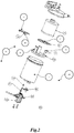
Figure 2 is an exploded view of the fuel filter ofFigure 1 ; -
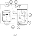
Figure 3 is a schematic representation of a drain off system incorporating the fuel filter ofFigure 1 ; and -
Figure 4 is a view of the fuel filter in use. - A fuel filter and a drain off system to separate and drain contaminants from a fuel filter according to an embodiment of the present invention are described below with reference to accompanying drawings
FIGS. 1 to 4 . - The
fuel filter 100 consists of afilter media 10 located inside afuel filter housing 12 generally towards the top thereof, abaffle 40 located inside the fuel filter housing and generally towards the bottom thereof afloat 20 incorporating amagnet 30, a switch 90, a protecting cover or stem 70 for the switch 90, asolenoid valve 80 and a faucet 110 for automatic drain water and, in this embodiment, afaucet 60 for manual drain water. Thebaffle 40, switch 90,solenoid valve 80 and faucet 110, collectively form adrainage assembly 25. The said switch 90 may, for example, be a Namur sensor, reed switch, proximity sensor, electromagnetic sensor, hall effect sensor or combination of thereof. - In this embodiment, the
baffle 40 includes a base 50 that is generally circular and is intended to conform to the internal diameter of the base of the housing so is pressed into location and retained as a press-fit or interference fit. In other embodiments alternate retaining arrangements may be employed however, such as fasteners or adhesives. Three retainer legs 52 extend upwardly generally parallel to the side wall of thehousing 12 and terminate at their upper ends with radially outwardly extending stops 54. The retainer legs have a degree of flex to enable the fitting of the float over the stops. Thebaffle 40 defines two regions inside thefuel filter housing 12, the upper compartment consisting of thefilter media 10 whereas the bottom compartment consisting of thedrainage assembly 25. - The
float 20 is dimensioned so as to be externally guided on thebaffles 40 and is able to move vertically in an unimpeded manner between the base 50 of thebaffle 40 and thestops 54. The specific gravity of thefloat 20 along with themagnet 30 incorporated therein, is less than the specific gravity of water but more than the specific gravity of the fuel used in the particular engine. In this embodiment thefloat 20 has a generallycircular arm 22 connected to acentral hub 24 by is multiple spokes 26. However thefloat 20 may be of any suitable geometrical shape and the shape of thefloat 20 that does not restrict the performance of the present invention. Thefloat 20 is dimensioned with such a clearance that thefloat 20 can move vertically with respect to thebaffles 40 even if there is a degree of contaminant build-up on the retainer legs 52 and therim 22. - The
magnet 30 is incorporated inside thefloat 20 at the radiallycentral hub 24 location of thefloat 20. Themagnet 30 placed inside thefloat 20 in a manner that it is sealed from the fluid inside the filter 100 (e.g. by being overmoulded). Themagnet 30, being protected inside thefloat 20, may increase working efficiency of the magnet, life span of the magnet and furthermore saved from external damage. The spokes provided on thefloat 20 also helps in regulating movement of thefloat 20 and themagnet 30 incorporated inside it. - The
filter housing 12 has a central aperture in its bottom wall. A combinedassembly 75 that incorporates the switch 90,stem 70,solenoid valve 80, and faucet 110 is mounted to an underside of the bottom wall such that thestem 70 projects up through the aperture and the switch is positioned in general vertical alignment with themagnet 30 when in its uppermost position restrained by the stops. Thestem 70 is offset from a central axis of the housing so as to be adjacent to thehub 24 but not impede motion of thefloat 20. - The switch 90 is protected by the protective cover or
stem 70. In this embodiment theassembly 75 is secured via threaded fasteners to the bottom wall and an O-ring type seal inhibits leakage. - A
fluid passage 82 extends through theassembly 75 from the base wall of the housing to the faucet 110 and is selectively closed by thesolenoid valve 80. Thesolenoid valve 80 is normally closed, and only permits fluid to flow through the passage when energised. Anadditional faucet 60 is optionally provided at the base of thefuel filter housing 50 to manually drain of water if required. - Referring to
FIG. 3 , in one embodiment of the present invention, the automatic water drain off system haselectrical system 300 which is connected to the switch 90 and thesolenoid valve 80. The electrical system optionally comprises an audio or visual indication means 340, atimer module 330 and arelay switch 320 andsecond relay switch 350. - Referring to
FIG. 4 , operation of the drain off system 400 is as follows. At the initial condition with no water contamination thefloat 20 rests on the base of thehousing 50 as its specific gravity is less than the fuel. As the engine operates, fuel enters thefuel filter 100 frominput port 410. The fuel is filtered through thefilter media 10 and water or other fluid present in the fuel accumulates in the lower region of thehousing 50. As the level of the accumulated water increases, thefloat 20 also rises. Thefloat 20 floats on the water surface because of specific gravity of the float along with themagnet 30 is less than the specific gravity of water. - Once the water reaches approximately the same level as the
stops 54 the magnet has risen to the level of the switch 90 and triggers the switch. - The switch 90 activates the
solenoid valve 80 to open thepassage 82 and allows water under gravity to drain from the faucet 110. - Referring to
FIG. 1 ,2 ,3 &4 ; in one embodiment the automatic water drain off system has anelectrical system 300 which is connected to the switch 90. When the engine is operating or the ignition switch is on and when electromagnetic connection is formed between themagnet 30 and the switch 90, then the circuit further energises an audio-visual type indicator 340 throughrelay switch 320. Activation of the audio-visual type indicator 340 indicates to the operator that the accumulated water has reached the upper limit and hence needs to drain it. This may act as a prompt for the operator to bring the vehicle to a halt before draining commences automatically as described above. Alternatively, a manual activation of asecond relay switch 350, energises a timer module of theelectrical system 300 which activates thesolenoid valve 80 for the pre-determined time to drain water (determined by how long is required for water to drain substantially from the housing from its maximum level). - When the engine is not operating but the ignition is on and when electromagnetic connection is formed between the
magnet 30 and the switch 90, then the switch 90 signals therelay switch 350. This automatically activates therelay switch 350 and further transfer signals to thetimer module 330 which activates thesolenoid valve 80 for the pre-determined time to drain water. - In another embodiment of the present invention, the
timer module 330 may be activated from therelay switch 350 provided in the said electrical system of the drainage system. Based on the audio-visual type indication 340 of the integrated auto drainage system, the operator may activate therelay switch 350 which further activates thetimer module 330. Thetimer module 330 further activates thesolenoid valve 80 for the pre-determined time to drain water from the fuel filter housing. - In another embodiment, when the operator switches on the vehicle with the
vehicle key 310 and at the same time the audio-visual indicator 340 is also in indication mode then the operator may switch on therelay switch 350 which further activates thesolenoid valve 80 for certain pre-determined time and hence all the accumulated water may drain out from the fuel filter housing during this operation. - In another embodiment of the present invention, as the accumulated water level goes down due to the activation of the
solenoid valve 80 for the pre-determined time, thefloat 20 also goes down along with water level. When all the accumulated water drains out from the fuel filter housing thereafter thefloat 20 rests on the base of thehousing 50. During this condition, thefloat 20 rests on the base of thehousing 50 in such manner that it closes thefluid passage 82 ormanual faucet 60 or both. Hence although thetimer module 330 and therelay switch 350 activate thesolenoid valve 80 for the pre-determined time but if all the accumulated water drains out from the fuel filter housing prior to the pre-determined time or prior to deactivation of thesolenoid valve 80, thereafter thefloat 20 closes the faucet 110 ormanual faucet 60 or both. This ensures no wastage of fuel and prevents fuel escaping into the environment. - In a further alternative embodiment a second switch may be provided proximate to the base of the housing so such that when the water has fully drained, closure of the valve is automatically triggered.
- It will be appreciated that, as described above, the drain off system may be incorporated within an existing fuel filter present in a vehicle with little or no adaptation because the
baffle 40 andfloat 20 may be push-fitted in a simple operation from above and the assembly may be secured by fasteners or other securement from below. Alternatively the housing may instead be adapted to internally include stops. Further, the housing may integrally incorporate the fluid passage and other components of theassembly 75. - In other embodiments the solenoid valve may be replaced by a pump or other suitable valve arrangement.
- The abovementioned description describes the exemplary embodiments of the present invention. One skilled in the art will easily understand from the description and from the accompanying drawings and claims that various changes, modifications and variations can be made therein without changing scope of the invention as defined by the following claims.
Claims (15)
- A fluid drain off system for a fuel filter, the system comprising a float, movable together with a trigger device for a switch, such as a magnet, in response to the level of fluid contaminant, a switch arranged to be selectively triggered by the trigger device upon the fluid contaminant reaching a predetermined level, and a fluid passage configured to be selectively opened in response to the triggering of the switch to allow fluid contaminants to be drained from the filter.
- A fluid drain off system according to claim 1, further comprising a baffle, wherein the float comprises a portion radially spaced from an axial centre of the housing in use, wherein the baffle comprises a guide radially spaced from an axial centre of the housing to guide the corresponding portion of the float, and wherein the trigger device is arranged substantially at the axial centre of the housing in use.
- A fluid drain off system according to claim 2 wherein the baffle comprises a stop for preventing or inhibiting the movement of the float past a predetermined position.
- A fluid drain off system according to claim 2 or claim 3 wherein the baffle comprises a plurality of guides, preferably three guides, spaced angularly with respect to the axial centre.
- A fluid drain off system according to claim 3 or claim 4 wherein the baffle comprises a plurality of stops, preferably three stops, spaced angularly with respect to the axial centre.
- A fluid drain off system according to any one of claims 2 to 5 wherein a radially outer surface of the guide guides the float, preferably wherein a radial clearance is provided between the guide and the float.
- A fluid drain off system according to any one of claims 2 to 6 wherein the baffle comprises a base arranged to seat on an inner base surface of the filter.
- A fluid drain off system according to any one of claims 2 to 7 wherein a portion of the baffle is configured for frictional, form-fitting or interference engagement with a corresponding surface of the filter such that the baffle may be retained in a desired position with respect to the baffle.
- A fluid drain off system according to any preceding claim wherein the fluid passage is arranged for mounting on a base of the filter at least partially selectively closing an aperture in the base of the filter.
- A fluid drain off system according to any preceding claim wherein the system further comprises a controller, the controller being configured to only open the fluid passage upon receipt of a signal indicating that a vehicle to which the system is fitted is stationary, and preferably further comprising an audio/visual indicator to indicate to an operator of a vehicle to which the system is fitted that fluid contaminant has reached the predetermined level, so as to prompt the user to bring the vehicle to a halt.
- A fluid drain off system according to any preceding claim, wherein shape of the float may be either of circular, square, triangle, rectangular, round, ring, hexagonal or any other geometric shape or combination of thereof having at least one spoke connected interior or exterior of the float which restrict movement or misalignment of the float over the baffles due to tilting of the filter in use.
- A fluid drain off system according to any preceding claim wherein the trigger device is substantially sealed from fluid ingress within the float.
- A fuel filter incorporating a fluid drain-off system according to any preceding claim.
- An IC engine incorporating a fluid drain-off system according to any one of claims 1 to 12.
- A vehicle, such as a working machine, or an electric generator incorporating a fluid drain-off system according to any one of claims 1 to 12.
Applications Claiming Priority (1)
| Application Number | Priority Date | Filing Date | Title |
|---|---|---|---|
| GB1701029.9A GB2561530B (en) | 2017-01-20 | 2017-01-20 | A fuel filter |
Publications (2)
| Publication Number | Publication Date |
|---|---|
| EP3351786A1 true EP3351786A1 (en) | 2018-07-25 |
| EP3351786B1 EP3351786B1 (en) | 2021-10-13 |
Family
ID=58463001
Family Applications (1)
| Application Number | Title | Priority Date | Filing Date |
|---|---|---|---|
| EP18151032.2A Active EP3351786B1 (en) | 2017-01-20 | 2018-01-10 | Fuel filter with fluid drain off system |
Country Status (5)
| Country | Link |
|---|---|
| US (1) | US10641220B2 (en) |
| EP (1) | EP3351786B1 (en) |
| JP (1) | JP6979886B2 (en) |
| CN (1) | CN108331688B (en) |
| GB (1) | GB2561530B (en) |
Cited By (2)
| Publication number | Priority date | Publication date | Assignee | Title |
|---|---|---|---|---|
| CN112023505A (en) * | 2020-08-11 | 2020-12-04 | 孙悦 | Cleaning device for wastewater treatment pool for rare earth oxide production and implementation method thereof |
| EP3816592A4 (en) * | 2018-08-30 | 2022-01-19 | Gree Electric Appliances, Inc. of Zhuhai | WATER TANK AND GAS HANDLER ASSEMBLY |
Families Citing this family (4)
| Publication number | Priority date | Publication date | Assignee | Title |
|---|---|---|---|---|
| EP3467295B1 (en) * | 2017-10-03 | 2021-09-08 | Rotex Automation Limited | A solenoid operated unit for detecting and removing undesired fluid with diagnostic metering |
| US10753330B2 (en) * | 2018-04-23 | 2020-08-25 | Caterpillar Inc. | Fuel-water separator self-draining valve with release member |
| US11797032B2 (en) * | 2019-09-05 | 2023-10-24 | Rotex Automation Limited | Auto drain valve |
| CN114061703B (en) * | 2021-11-17 | 2023-07-21 | 河北机电职业技术学院 | Oil level monitoring alarm device of automobile hydraulic system |
Citations (6)
| Publication number | Priority date | Publication date | Assignee | Title |
|---|---|---|---|---|
| GB1600271A (en) * | 1978-04-25 | 1981-10-14 | Gough D V | Separating devices |
| GB2097927A (en) * | 1981-04-18 | 1982-11-10 | Bosch Gmbh Robert | Liquid level indication |
| FR2533667A1 (en) * | 1982-09-24 | 1984-03-30 | Thibonnet Bernard | Automatic bleed. |
| EP1287252A1 (en) * | 2000-06-05 | 2003-03-05 | UFI Universal Filter International S.p.A. | Apparatus for automatically draining water accumulated in a fuel filter of a vehicle, particularly for diesel engines |
| US20080150552A1 (en) * | 2006-12-21 | 2008-06-26 | Straub Robert D | Apparatus and method for sensing water within a fuel-water separator assembly |
| US20140365101A1 (en) * | 2012-01-16 | 2014-12-11 | Hitachi Construction Machinery Co., Ltd. | Industrial Machine |
Family Cites Families (13)
| Publication number | Priority date | Publication date | Assignee | Title |
|---|---|---|---|---|
| GB1408291A (en) * | 1972-04-19 | 1975-10-01 | Gough D V | Liquid separators |
| JPS5912981Y2 (en) * | 1979-03-16 | 1984-04-18 | 東京濾器株式会社 | fuel filter |
| JPS5738656A (en) * | 1980-08-13 | 1982-03-03 | Toyota Motor Corp | Automatic drawing for water separator of automobile fuel system |
| JPH0634884B2 (en) * | 1986-10-06 | 1994-05-11 | 三信工業株式会社 | Fuel filter drainage system |
| KR100349638B1 (en) * | 1999-08-31 | 2002-08-21 | 현대자동차주식회사 | Fuel filter equiped auto draining device |
| IT1311043B1 (en) * | 1999-11-03 | 2002-02-28 | Ufi Universal Filter Int Spa | GROUP FOR THE AUTOMATIC PURIFICATION OF SEPARATE WATER IN A VEHICLE FUEL FILTER, IN PARTICULAR FOR DIESEL ENGINES. |
| US6645372B2 (en) * | 2000-06-05 | 2003-11-11 | Ufi Universal Filter International S.P.A | Unit for draining water from a fuel filter |
| KR100384298B1 (en) * | 2000-11-20 | 2003-05-16 | 현대자동차주식회사 | Water drain apparatus in fuel filter |
| ITTO20030097A1 (en) * | 2003-02-11 | 2004-08-12 | Fiat Ricerche | LEVEL SENSOR DEVICE FOR A TANK OF |
| US20080110812A1 (en) * | 2006-11-13 | 2008-05-15 | Mahle Tennex Industries, Inc. | Separated water treatment system for diesel fuel engine |
| US8409446B2 (en) * | 2009-08-21 | 2013-04-02 | Cummins Filtration Ip, Inc. | Automatic draining system to drain fluid from a filter |
| EP2872348B1 (en) * | 2012-07-12 | 2020-01-15 | Eaton Corporation | Flapper valve with guide legs |
| CN205207213U (en) * | 2015-12-18 | 2016-05-04 | 山东鲁泰控股集团有限公司鹿洼煤矿 | Colliery sump automatic drainage system |
-
2017
- 2017-01-20 GB GB1701029.9A patent/GB2561530B/en active Active
-
2018
- 2018-01-10 EP EP18151032.2A patent/EP3351786B1/en active Active
- 2018-01-18 JP JP2018006100A patent/JP6979886B2/en active Active
- 2018-01-19 CN CN201810054889.XA patent/CN108331688B/en active Active
- 2018-01-19 US US15/875,946 patent/US10641220B2/en active Active
Patent Citations (6)
| Publication number | Priority date | Publication date | Assignee | Title |
|---|---|---|---|---|
| GB1600271A (en) * | 1978-04-25 | 1981-10-14 | Gough D V | Separating devices |
| GB2097927A (en) * | 1981-04-18 | 1982-11-10 | Bosch Gmbh Robert | Liquid level indication |
| FR2533667A1 (en) * | 1982-09-24 | 1984-03-30 | Thibonnet Bernard | Automatic bleed. |
| EP1287252A1 (en) * | 2000-06-05 | 2003-03-05 | UFI Universal Filter International S.p.A. | Apparatus for automatically draining water accumulated in a fuel filter of a vehicle, particularly for diesel engines |
| US20080150552A1 (en) * | 2006-12-21 | 2008-06-26 | Straub Robert D | Apparatus and method for sensing water within a fuel-water separator assembly |
| US20140365101A1 (en) * | 2012-01-16 | 2014-12-11 | Hitachi Construction Machinery Co., Ltd. | Industrial Machine |
Cited By (2)
| Publication number | Priority date | Publication date | Assignee | Title |
|---|---|---|---|---|
| EP3816592A4 (en) * | 2018-08-30 | 2022-01-19 | Gree Electric Appliances, Inc. of Zhuhai | WATER TANK AND GAS HANDLER ASSEMBLY |
| CN112023505A (en) * | 2020-08-11 | 2020-12-04 | 孙悦 | Cleaning device for wastewater treatment pool for rare earth oxide production and implementation method thereof |
Also Published As
| Publication number | Publication date |
|---|---|
| CN108331688B (en) | 2022-03-08 |
| JP2018135879A (en) | 2018-08-30 |
| US20180209387A1 (en) | 2018-07-26 |
| CN108331688A (en) | 2018-07-27 |
| US10641220B2 (en) | 2020-05-05 |
| EP3351786B1 (en) | 2021-10-13 |
| JP6979886B2 (en) | 2021-12-15 |
| GB201701029D0 (en) | 2017-03-08 |
| GB2561530B (en) | 2022-01-12 |
| GB2561530A (en) | 2018-10-24 |
Similar Documents
| Publication | Publication Date | Title |
|---|---|---|
| US10641220B2 (en) | Fuel filter | |
| US8871084B2 (en) | Fluid filter comprising a protected liquid sensor | |
| US4602605A (en) | Entering fuel injection system of a diesel engine | |
| JP2614364B2 (en) | Fuel supply device | |
| US5755252A (en) | Control valve with two-stage shutoff and peel away opening action | |
| JP3909231B2 (en) | Vent valve and fuel pump module | |
| EP2969109B1 (en) | Automatic drain for fuel processor | |
| KR20010042195A (en) | Automotive evaporative leak detection system | |
| JP2006103677A (en) | Valve assembly and oil supply sensor | |
| EP3789605B1 (en) | Auto drain valve | |
| US8763626B2 (en) | Valve for the venting circuit of a liquid tank | |
| US8479763B2 (en) | Electronic venting and mechanical roll over valve | |
| AU2005202776A1 (en) | Rapid response fuel tank rollover/vent valve | |
| JP4864937B2 (en) | Oil level regulator for liquid fuel combustion equipment | |
| JP3954155B2 (en) | Liquid outflow prevention valve device | |
| US20170241309A1 (en) | Drainage device | |
| JPS5929739A (en) | Fuel purifier with electric water-level indicator | |
| IE950554A1 (en) | Liquid level monitoring apparatus | |
| JP2011043272A (en) | Storage water heater | |
| US6895990B1 (en) | Water heater fail safe apparatus | |
| JP3994286B2 (en) | Fuel tank level detection valve | |
| US9494114B2 (en) | Water discharge device | |
| US20100224538A1 (en) | Method Of Filtering And Filter Device | |
| JP4487915B2 (en) | Fuel shut-off valve | |
| JPS60175761A (en) | Fuel system for internal combustion engine |
Legal Events
| Date | Code | Title | Description |
|---|---|---|---|
| PUAI | Public reference made under article 153(3) epc to a published international application that has entered the european phase |
Free format text: ORIGINAL CODE: 0009012 |
|
| STAA | Information on the status of an ep patent application or granted ep patent |
Free format text: STATUS: THE APPLICATION HAS BEEN PUBLISHED |
|
| AK | Designated contracting states |
Kind code of ref document: A1 Designated state(s): AL AT BE BG CH CY CZ DE DK EE ES FI FR GB GR HR HU IE IS IT LI LT LU LV MC MK MT NL NO PL PT RO RS SE SI SK SM TR |
|
| AX | Request for extension of the european patent |
Extension state: BA ME |
|
| STAA | Information on the status of an ep patent application or granted ep patent |
Free format text: STATUS: REQUEST FOR EXAMINATION WAS MADE |
|
| 17P | Request for examination filed |
Effective date: 20190111 |
|
| RBV | Designated contracting states (corrected) |
Designated state(s): AL AT BE BG CH CY CZ DE DK EE ES FI FR GB GR HR HU IE IS IT LI LT LU LV MC MK MT NL NO PL PT RO RS SE SI SK SM TR |
|
| STAA | Information on the status of an ep patent application or granted ep patent |
Free format text: STATUS: EXAMINATION IS IN PROGRESS |
|
| 17Q | First examination report despatched |
Effective date: 20190412 |
|
| GRAP | Despatch of communication of intention to grant a patent |
Free format text: ORIGINAL CODE: EPIDOSNIGR1 |
|
| STAA | Information on the status of an ep patent application or granted ep patent |
Free format text: STATUS: GRANT OF PATENT IS INTENDED |
|
| GRAJ | Information related to disapproval of communication of intention to grant by the applicant or resumption of examination proceedings by the epo deleted |
Free format text: ORIGINAL CODE: EPIDOSDIGR1 |
|
| STAA | Information on the status of an ep patent application or granted ep patent |
Free format text: STATUS: EXAMINATION IS IN PROGRESS |
|
| INTG | Intention to grant announced |
Effective date: 20210322 |
|
| GRAP | Despatch of communication of intention to grant a patent |
Free format text: ORIGINAL CODE: EPIDOSNIGR1 |
|
| STAA | Information on the status of an ep patent application or granted ep patent |
Free format text: STATUS: GRANT OF PATENT IS INTENDED |
|
| INTC | Intention to grant announced (deleted) | ||
| INTG | Intention to grant announced |
Effective date: 20210504 |
|
| GRAS | Grant fee paid |
Free format text: ORIGINAL CODE: EPIDOSNIGR3 |
|
| GRAA | (expected) grant |
Free format text: ORIGINAL CODE: 0009210 |
|
| STAA | Information on the status of an ep patent application or granted ep patent |
Free format text: STATUS: THE PATENT HAS BEEN GRANTED |
|
| AK | Designated contracting states |
Kind code of ref document: B1 Designated state(s): AL AT BE BG CH CY CZ DE DK EE ES FI FR GB GR HR HU IE IS IT LI LT LU LV MC MK MT NL NO PL PT RO RS SE SI SK SM TR |
|
| REG | Reference to a national code |
Ref country code: GB Ref legal event code: FG4D |
|
| REG | Reference to a national code |
Ref country code: CH Ref legal event code: EP |
|
| REG | Reference to a national code |
Ref country code: DE Ref legal event code: R096 Ref document number: 602018024863 Country of ref document: DE |
|
| REG | Reference to a national code |
Ref country code: IE Ref legal event code: FG4D |
|
| REG | Reference to a national code |
Ref country code: AT Ref legal event code: REF Ref document number: 1438372 Country of ref document: AT Kind code of ref document: T Effective date: 20211115 |
|
| REG | Reference to a national code |
Ref country code: LT Ref legal event code: MG9D |
|
| REG | Reference to a national code |
Ref country code: NL Ref legal event code: MP Effective date: 20211013 |
|
| REG | Reference to a national code |
Ref country code: AT Ref legal event code: MK05 Ref document number: 1438372 Country of ref document: AT Kind code of ref document: T Effective date: 20211013 |
|
| PG25 | Lapsed in a contracting state [announced via postgrant information from national office to epo] |
Ref country code: RS Free format text: LAPSE BECAUSE OF FAILURE TO SUBMIT A TRANSLATION OF THE DESCRIPTION OR TO PAY THE FEE WITHIN THE PRESCRIBED TIME-LIMIT Effective date: 20211013 Ref country code: LT Free format text: LAPSE BECAUSE OF FAILURE TO SUBMIT A TRANSLATION OF THE DESCRIPTION OR TO PAY THE FEE WITHIN THE PRESCRIBED TIME-LIMIT Effective date: 20211013 Ref country code: FI Free format text: LAPSE BECAUSE OF FAILURE TO SUBMIT A TRANSLATION OF THE DESCRIPTION OR TO PAY THE FEE WITHIN THE PRESCRIBED TIME-LIMIT Effective date: 20211013 Ref country code: BG Free format text: LAPSE BECAUSE OF FAILURE TO SUBMIT A TRANSLATION OF THE DESCRIPTION OR TO PAY THE FEE WITHIN THE PRESCRIBED TIME-LIMIT Effective date: 20220113 Ref country code: AT Free format text: LAPSE BECAUSE OF FAILURE TO SUBMIT A TRANSLATION OF THE DESCRIPTION OR TO PAY THE FEE WITHIN THE PRESCRIBED TIME-LIMIT Effective date: 20211013 |
|
| PG25 | Lapsed in a contracting state [announced via postgrant information from national office to epo] |
Ref country code: IS Free format text: LAPSE BECAUSE OF FAILURE TO SUBMIT A TRANSLATION OF THE DESCRIPTION OR TO PAY THE FEE WITHIN THE PRESCRIBED TIME-LIMIT Effective date: 20220213 Ref country code: SE Free format text: LAPSE BECAUSE OF FAILURE TO SUBMIT A TRANSLATION OF THE DESCRIPTION OR TO PAY THE FEE WITHIN THE PRESCRIBED TIME-LIMIT Effective date: 20211013 Ref country code: PT Free format text: LAPSE BECAUSE OF FAILURE TO SUBMIT A TRANSLATION OF THE DESCRIPTION OR TO PAY THE FEE WITHIN THE PRESCRIBED TIME-LIMIT Effective date: 20220214 Ref country code: PL Free format text: LAPSE BECAUSE OF FAILURE TO SUBMIT A TRANSLATION OF THE DESCRIPTION OR TO PAY THE FEE WITHIN THE PRESCRIBED TIME-LIMIT Effective date: 20211013 Ref country code: NO Free format text: LAPSE BECAUSE OF FAILURE TO SUBMIT A TRANSLATION OF THE DESCRIPTION OR TO PAY THE FEE WITHIN THE PRESCRIBED TIME-LIMIT Effective date: 20220113 Ref country code: NL Free format text: LAPSE BECAUSE OF FAILURE TO SUBMIT A TRANSLATION OF THE DESCRIPTION OR TO PAY THE FEE WITHIN THE PRESCRIBED TIME-LIMIT Effective date: 20211013 Ref country code: LV Free format text: LAPSE BECAUSE OF FAILURE TO SUBMIT A TRANSLATION OF THE DESCRIPTION OR TO PAY THE FEE WITHIN THE PRESCRIBED TIME-LIMIT Effective date: 20211013 Ref country code: HR Free format text: LAPSE BECAUSE OF FAILURE TO SUBMIT A TRANSLATION OF THE DESCRIPTION OR TO PAY THE FEE WITHIN THE PRESCRIBED TIME-LIMIT Effective date: 20211013 Ref country code: GR Free format text: LAPSE BECAUSE OF FAILURE TO SUBMIT A TRANSLATION OF THE DESCRIPTION OR TO PAY THE FEE WITHIN THE PRESCRIBED TIME-LIMIT Effective date: 20220114 Ref country code: ES Free format text: LAPSE BECAUSE OF FAILURE TO SUBMIT A TRANSLATION OF THE DESCRIPTION OR TO PAY THE FEE WITHIN THE PRESCRIBED TIME-LIMIT Effective date: 20211013 |
|
| REG | Reference to a national code |
Ref country code: DE Ref legal event code: R097 Ref document number: 602018024863 Country of ref document: DE |
|
| PG25 | Lapsed in a contracting state [announced via postgrant information from national office to epo] |
Ref country code: SM Free format text: LAPSE BECAUSE OF FAILURE TO SUBMIT A TRANSLATION OF THE DESCRIPTION OR TO PAY THE FEE WITHIN THE PRESCRIBED TIME-LIMIT Effective date: 20211013 Ref country code: SK Free format text: LAPSE BECAUSE OF FAILURE TO SUBMIT A TRANSLATION OF THE DESCRIPTION OR TO PAY THE FEE WITHIN THE PRESCRIBED TIME-LIMIT Effective date: 20211013 Ref country code: RO Free format text: LAPSE BECAUSE OF FAILURE TO SUBMIT A TRANSLATION OF THE DESCRIPTION OR TO PAY THE FEE WITHIN THE PRESCRIBED TIME-LIMIT Effective date: 20211013 Ref country code: EE Free format text: LAPSE BECAUSE OF FAILURE TO SUBMIT A TRANSLATION OF THE DESCRIPTION OR TO PAY THE FEE WITHIN THE PRESCRIBED TIME-LIMIT Effective date: 20211013 Ref country code: DK Free format text: LAPSE BECAUSE OF FAILURE TO SUBMIT A TRANSLATION OF THE DESCRIPTION OR TO PAY THE FEE WITHIN THE PRESCRIBED TIME-LIMIT Effective date: 20211013 Ref country code: CZ Free format text: LAPSE BECAUSE OF FAILURE TO SUBMIT A TRANSLATION OF THE DESCRIPTION OR TO PAY THE FEE WITHIN THE PRESCRIBED TIME-LIMIT Effective date: 20211013 |
|
| PLBE | No opposition filed within time limit |
Free format text: ORIGINAL CODE: 0009261 |
|
| STAA | Information on the status of an ep patent application or granted ep patent |
Free format text: STATUS: NO OPPOSITION FILED WITHIN TIME LIMIT |
|
| PG25 | Lapsed in a contracting state [announced via postgrant information from national office to epo] |
Ref country code: MC Free format text: LAPSE BECAUSE OF FAILURE TO SUBMIT A TRANSLATION OF THE DESCRIPTION OR TO PAY THE FEE WITHIN THE PRESCRIBED TIME-LIMIT Effective date: 20211013 |
|
| REG | Reference to a national code |
Ref country code: CH Ref legal event code: PL |
|
| 26N | No opposition filed |
Effective date: 20220714 |
|
| REG | Reference to a national code |
Ref country code: BE Ref legal event code: MM Effective date: 20220131 |
|
| PG25 | Lapsed in a contracting state [announced via postgrant information from national office to epo] |
Ref country code: LU Free format text: LAPSE BECAUSE OF NON-PAYMENT OF DUE FEES Effective date: 20220110 Ref country code: AL Free format text: LAPSE BECAUSE OF FAILURE TO SUBMIT A TRANSLATION OF THE DESCRIPTION OR TO PAY THE FEE WITHIN THE PRESCRIBED TIME-LIMIT Effective date: 20211013 |
|
| PG25 | Lapsed in a contracting state [announced via postgrant information from national office to epo] |
Ref country code: SI Free format text: LAPSE BECAUSE OF FAILURE TO SUBMIT A TRANSLATION OF THE DESCRIPTION OR TO PAY THE FEE WITHIN THE PRESCRIBED TIME-LIMIT Effective date: 20211013 Ref country code: BE Free format text: LAPSE BECAUSE OF NON-PAYMENT OF DUE FEES Effective date: 20220131 |
|
| PG25 | Lapsed in a contracting state [announced via postgrant information from national office to epo] |
Ref country code: LI Free format text: LAPSE BECAUSE OF NON-PAYMENT OF DUE FEES Effective date: 20220131 Ref country code: CH Free format text: LAPSE BECAUSE OF NON-PAYMENT OF DUE FEES Effective date: 20220131 |
|
| PG25 | Lapsed in a contracting state [announced via postgrant information from national office to epo] |
Ref country code: IE Free format text: LAPSE BECAUSE OF NON-PAYMENT OF DUE FEES Effective date: 20220110 |
|
| P01 | Opt-out of the competence of the unified patent court (upc) registered |
Effective date: 20230525 |
|
| PG25 | Lapsed in a contracting state [announced via postgrant information from national office to epo] |
Ref country code: HU Free format text: LAPSE BECAUSE OF FAILURE TO SUBMIT A TRANSLATION OF THE DESCRIPTION OR TO PAY THE FEE WITHIN THE PRESCRIBED TIME-LIMIT; INVALID AB INITIO Effective date: 20180110 |
|
| PG25 | Lapsed in a contracting state [announced via postgrant information from national office to epo] |
Ref country code: MK Free format text: LAPSE BECAUSE OF FAILURE TO SUBMIT A TRANSLATION OF THE DESCRIPTION OR TO PAY THE FEE WITHIN THE PRESCRIBED TIME-LIMIT Effective date: 20211013 Ref country code: CY Free format text: LAPSE BECAUSE OF FAILURE TO SUBMIT A TRANSLATION OF THE DESCRIPTION OR TO PAY THE FEE WITHIN THE PRESCRIBED TIME-LIMIT Effective date: 20211013 |
|
| PG25 | Lapsed in a contracting state [announced via postgrant information from national office to epo] |
Ref country code: TR Free format text: LAPSE BECAUSE OF FAILURE TO SUBMIT A TRANSLATION OF THE DESCRIPTION OR TO PAY THE FEE WITHIN THE PRESCRIBED TIME-LIMIT Effective date: 20211013 |
|
| PG25 | Lapsed in a contracting state [announced via postgrant information from national office to epo] |
Ref country code: MT Free format text: LAPSE BECAUSE OF FAILURE TO SUBMIT A TRANSLATION OF THE DESCRIPTION OR TO PAY THE FEE WITHIN THE PRESCRIBED TIME-LIMIT Effective date: 20211013 |
|
| PGFP | Annual fee paid to national office [announced via postgrant information from national office to epo] |
Ref country code: GB Payment date: 20260116 Year of fee payment: 9 |
|
| PGFP | Annual fee paid to national office [announced via postgrant information from national office to epo] |
Ref country code: DE Payment date: 20260121 Year of fee payment: 9 |
|
| PGFP | Annual fee paid to national office [announced via postgrant information from national office to epo] |
Ref country code: IT Payment date: 20260123 Year of fee payment: 9 |
|
| PGFP | Annual fee paid to national office [announced via postgrant information from national office to epo] |
Ref country code: FR Payment date: 20260123 Year of fee payment: 9 |