EP3351456A1 - Electric power steering device - Google Patents
Electric power steering device Download PDFInfo
- Publication number
- EP3351456A1 EP3351456A1 EP16846579.7A EP16846579A EP3351456A1 EP 3351456 A1 EP3351456 A1 EP 3351456A1 EP 16846579 A EP16846579 A EP 16846579A EP 3351456 A1 EP3351456 A1 EP 3351456A1
- Authority
- EP
- European Patent Office
- Prior art keywords
- angle
- motor
- electric power
- power steering
- steering apparatus
- Prior art date
- Legal status (The legal status is an assumption and is not a legal conclusion. Google has not performed a legal analysis and makes no representation as to the accuracy of the status listed.)
- Granted
Links
Images






Classifications
-
- B—PERFORMING OPERATIONS; TRANSPORTING
- B62—LAND VEHICLES FOR TRAVELLING OTHERWISE THAN ON RAILS
- B62D—MOTOR VEHICLES; TRAILERS
- B62D5/00—Power-assisted or power-driven steering
- B62D5/04—Power-assisted or power-driven steering electrical, e.g. using an electric servo-motor connected to, or forming part of, the steering gear
- B62D5/0457—Power-assisted or power-driven steering electrical, e.g. using an electric servo-motor connected to, or forming part of, the steering gear characterised by control features of the drive means as such
- B62D5/0481—Power-assisted or power-driven steering electrical, e.g. using an electric servo-motor connected to, or forming part of, the steering gear characterised by control features of the drive means as such monitoring the steering system, e.g. failures
- B62D5/0487—Power-assisted or power-driven steering electrical, e.g. using an electric servo-motor connected to, or forming part of, the steering gear characterised by control features of the drive means as such monitoring the steering system, e.g. failures detecting motor faults
-
- B—PERFORMING OPERATIONS; TRANSPORTING
- B62—LAND VEHICLES FOR TRAVELLING OTHERWISE THAN ON RAILS
- B62D—MOTOR VEHICLES; TRAILERS
- B62D5/00—Power-assisted or power-driven steering
- B62D5/04—Power-assisted or power-driven steering electrical, e.g. using an electric servo-motor connected to, or forming part of, the steering gear
- B62D5/0457—Power-assisted or power-driven steering electrical, e.g. using an electric servo-motor connected to, or forming part of, the steering gear characterised by control features of the drive means as such
- B62D5/0481—Power-assisted or power-driven steering electrical, e.g. using an electric servo-motor connected to, or forming part of, the steering gear characterised by control features of the drive means as such monitoring the steering system, e.g. failures
-
- B—PERFORMING OPERATIONS; TRANSPORTING
- B62—LAND VEHICLES FOR TRAVELLING OTHERWISE THAN ON RAILS
- B62D—MOTOR VEHICLES; TRAILERS
- B62D5/00—Power-assisted or power-driven steering
- B62D5/04—Power-assisted or power-driven steering electrical, e.g. using an electric servo-motor connected to, or forming part of, the steering gear
- B62D5/043—Power-assisted or power-driven steering electrical, e.g. using an electric servo-motor connected to, or forming part of, the steering gear characterised by clutch means between driving element, e.g. motor, and driven element, e.g. steering column or steering gear
-
- B—PERFORMING OPERATIONS; TRANSPORTING
- B62—LAND VEHICLES FOR TRAVELLING OTHERWISE THAN ON RAILS
- B62D—MOTOR VEHICLES; TRAILERS
- B62D5/00—Power-assisted or power-driven steering
- B62D5/04—Power-assisted or power-driven steering electrical, e.g. using an electric servo-motor connected to, or forming part of, the steering gear
- B62D5/0457—Power-assisted or power-driven steering electrical, e.g. using an electric servo-motor connected to, or forming part of, the steering gear characterised by control features of the drive means as such
- B62D5/0481—Power-assisted or power-driven steering electrical, e.g. using an electric servo-motor connected to, or forming part of, the steering gear characterised by control features of the drive means as such monitoring the steering system, e.g. failures
- B62D5/0484—Power-assisted or power-driven steering electrical, e.g. using an electric servo-motor connected to, or forming part of, the steering gear characterised by control features of the drive means as such monitoring the steering system, e.g. failures for reaction to failures, e.g. limp home
-
- B—PERFORMING OPERATIONS; TRANSPORTING
- B62—LAND VEHICLES FOR TRAVELLING OTHERWISE THAN ON RAILS
- B62D—MOTOR VEHICLES; TRAILERS
- B62D5/00—Power-assisted or power-driven steering
- B62D5/04—Power-assisted or power-driven steering electrical, e.g. using an electric servo-motor connected to, or forming part of, the steering gear
- B62D5/0457—Power-assisted or power-driven steering electrical, e.g. using an electric servo-motor connected to, or forming part of, the steering gear characterised by control features of the drive means as such
- B62D5/0481—Power-assisted or power-driven steering electrical, e.g. using an electric servo-motor connected to, or forming part of, the steering gear characterised by control features of the drive means as such monitoring the steering system, e.g. failures
- B62D5/049—Power-assisted or power-driven steering electrical, e.g. using an electric servo-motor connected to, or forming part of, the steering gear characterised by control features of the drive means as such monitoring the steering system, e.g. failures detecting sensor failures
-
- B—PERFORMING OPERATIONS; TRANSPORTING
- B62—LAND VEHICLES FOR TRAVELLING OTHERWISE THAN ON RAILS
- B62D—MOTOR VEHICLES; TRAILERS
- B62D6/00—Arrangements for automatically controlling steering depending on driving conditions sensed and responded to, e.g. control circuits
-
- B—PERFORMING OPERATIONS; TRANSPORTING
- B62—LAND VEHICLES FOR TRAVELLING OTHERWISE THAN ON RAILS
- B62D—MOTOR VEHICLES; TRAILERS
- B62D6/00—Arrangements for automatically controlling steering depending on driving conditions sensed and responded to, e.g. control circuits
- B62D6/08—Arrangements for automatically controlling steering depending on driving conditions sensed and responded to, e.g. control circuits responsive only to driver input torque
- B62D6/10—Arrangements for automatically controlling steering depending on driving conditions sensed and responded to, e.g. control circuits responsive only to driver input torque characterised by means for sensing or determining torque
-
- H—ELECTRICITY
- H02—GENERATION; CONVERSION OR DISTRIBUTION OF ELECTRIC POWER
- H02P—CONTROL OR REGULATION OF ELECTRIC MOTORS, ELECTRIC GENERATORS OR DYNAMO-ELECTRIC CONVERTERS; CONTROLLING TRANSFORMERS, REACTORS OR CHOKE COILS
- H02P27/00—Arrangements or methods for the control of AC motors characterised by the kind of supply voltage
- H02P27/04—Arrangements or methods for the control of AC motors characterised by the kind of supply voltage using variable-frequency supply voltage, e.g. inverter or converter supply voltage
- H02P27/06—Arrangements or methods for the control of AC motors characterised by the kind of supply voltage using variable-frequency supply voltage, e.g. inverter or converter supply voltage using DC to AC converters or inverters
-
- H—ELECTRICITY
- H02—GENERATION; CONVERSION OR DISTRIBUTION OF ELECTRIC POWER
- H02P—CONTROL OR REGULATION OF ELECTRIC MOTORS, ELECTRIC GENERATORS OR DYNAMO-ELECTRIC CONVERTERS; CONTROLLING TRANSFORMERS, REACTORS OR CHOKE COILS
- H02P27/00—Arrangements or methods for the control of AC motors characterised by the kind of supply voltage
- H02P27/04—Arrangements or methods for the control of AC motors characterised by the kind of supply voltage using variable-frequency supply voltage, e.g. inverter or converter supply voltage
- H02P27/06—Arrangements or methods for the control of AC motors characterised by the kind of supply voltage using variable-frequency supply voltage, e.g. inverter or converter supply voltage using DC to AC converters or inverters
- H02P27/08—Arrangements or methods for the control of AC motors characterised by the kind of supply voltage using variable-frequency supply voltage, e.g. inverter or converter supply voltage using DC to AC converters or inverters with pulse width modulation
- H02P27/085—Arrangements or methods for the control of AC motors characterised by the kind of supply voltage using variable-frequency supply voltage, e.g. inverter or converter supply voltage using DC to AC converters or inverters with pulse width modulation wherein the PWM mode is adapted on the running conditions of the motor, e.g. the switching frequency
-
- H—ELECTRICITY
- H02—GENERATION; CONVERSION OR DISTRIBUTION OF ELECTRIC POWER
- H02P—CONTROL OR REGULATION OF ELECTRIC MOTORS, ELECTRIC GENERATORS OR DYNAMO-ELECTRIC CONVERTERS; CONTROLLING TRANSFORMERS, REACTORS OR CHOKE COILS
- H02P29/00—Arrangements for regulating or controlling electric motors, appropriate for both AC and DC motors
- H02P29/02—Providing protection against overload without automatic interruption of supply
- H02P29/024—Detecting a fault condition, e.g. short circuit, locked rotor, open circuit or loss of load
- H02P29/028—Detecting a fault condition, e.g. short circuit, locked rotor, open circuit or loss of load the motor continuing operation despite the fault condition, e.g. eliminating, compensating for or remedying the fault
-
- H—ELECTRICITY
- H02—GENERATION; CONVERSION OR DISTRIBUTION OF ELECTRIC POWER
- H02P—CONTROL OR REGULATION OF ELECTRIC MOTORS, ELECTRIC GENERATORS OR DYNAMO-ELECTRIC CONVERTERS; CONTROLLING TRANSFORMERS, REACTORS OR CHOKE COILS
- H02P29/00—Arrangements for regulating or controlling electric motors, appropriate for both AC and DC motors
- H02P29/02—Providing protection against overload without automatic interruption of supply
- H02P29/032—Preventing damage to the motor, e.g. setting individual current limits for different drive conditions
-
- H—ELECTRICITY
- H02—GENERATION; CONVERSION OR DISTRIBUTION OF ELECTRIC POWER
- H02P—CONTROL OR REGULATION OF ELECTRIC MOTORS, ELECTRIC GENERATORS OR DYNAMO-ELECTRIC CONVERTERS; CONTROLLING TRANSFORMERS, REACTORS OR CHOKE COILS
- H02P6/00—Arrangements for controlling synchronous motors or other dynamo-electric motors using electronic commutation dependent on the rotor position; Electronic commutators therefor
- H02P6/14—Electronic commutators
- H02P6/16—Circuit arrangements for detecting position
- H02P6/18—Circuit arrangements for detecting position without separate position detecting elements
-
- H—ELECTRICITY
- H02—GENERATION; CONVERSION OR DISTRIBUTION OF ELECTRIC POWER
- H02P—CONTROL OR REGULATION OF ELECTRIC MOTORS, ELECTRIC GENERATORS OR DYNAMO-ELECTRIC CONVERTERS; CONTROLLING TRANSFORMERS, REACTORS OR CHOKE COILS
- H02P25/00—Arrangements or methods for the control of AC motors characterised by the kind of AC motor or by structural details
- H02P25/16—Arrangements or methods for the control of AC motors characterised by the kind of AC motor or by structural details characterised by the circuit arrangement or by the kind of wiring
- H02P25/22—Multiple windings; Windings for more than three phases
-
- H—ELECTRICITY
- H02—GENERATION; CONVERSION OR DISTRIBUTION OF ELECTRIC POWER
- H02P—CONTROL OR REGULATION OF ELECTRIC MOTORS, ELECTRIC GENERATORS OR DYNAMO-ELECTRIC CONVERTERS; CONTROLLING TRANSFORMERS, REACTORS OR CHOKE COILS
- H02P6/00—Arrangements for controlling synchronous motors or other dynamo-electric motors using electronic commutation dependent on the rotor position; Electronic commutators therefor
- H02P6/14—Electronic commutators
- H02P6/16—Circuit arrangements for detecting position
- H02P6/17—Circuit arrangements for detecting position and for generating speed information
Definitions
- the present invention relates to an electric power steering apparatus that applies an assist torque to a steering system of a vehicle by a motor by means of a current command value calculated based on at least a steering torque, and in particular to the electric power steering apparatus, for a brushless motor to be necessary to control by obtaining a motor rotational angle, that continues to assist-control by accurately estimating the motor rotational angle when an angle detecting system is failed (including an abnormality).
- An electric power steering apparatus which provides a steering system of a vehicle with a steering assist torque (an assist torque) by a rotational torque of a motor, applies the steering assist torque to a steering shaft or a rack shaft by means of a transmission mechanism such as gears by using a driving force of the motor which is controlled by electric power supplied from an electric power supplying section (an inverter).
- an electric power steering apparatus performs a feed-back control of a motor current.
- the feed-back control adjusts a voltage supplied to the motor so that a difference between a steering assist command value (a current command value) and a detected motor current value becomes small, and the adjustment of the voltage supplied to the motor is generally performed by an adjustment of duty command values of a pulse width modulation (PWM) control.
- PWM pulse width modulation
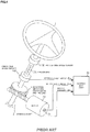
- a column shaft (a steering shaft or a handle shaft) 2 connected to a handle 1 is connected to steered wheels 8L and 8R through reduction gears 3, universal joints 4a and 4b, a pinion-and-rack mechanism 5, and tie rods 6a and 6b, further via hub units 7a and 7b.
- the steering shaft 2 is provided with a torque sensor 10 for detecting a steering torque Th of the handle 1 and a steering angle sensor 14 for detecting a steering angle ⁇ , and a motor 20 for assisting the steering torque of the handle 1 is connected to the column shaft 2 through the reduction gears 3.
- the electric power is supplied to a control unit (ECU) 30 for controlling the electric power steering apparatus from a battery 13, and an ignition key signal is inputted into the control unit 30 through an ignition key 11.
- the control unit 30 calculates a current command value of an assist command (a steering assist command) on the basis of the steering torque Th detected by the torque sensor 10 and a vehicle speed Vs detected by a vehicle speed sensor 12, and controls a current supplied to the motor 20 for the EPS by means of a voltage control command value Vref obtained by performing a compensation or the like to the current command value.
- the steering angle ⁇ is detected from the steering angle sensor 14, and it is possible to obtain the steering angle from a rotational sensor such as a resolver which is connected to the motor 20.
- a controller area network (CAN) 40 to send/receive various information and signals on the vehicle is connected to the control unit 100, and it is also possible to receive the vehicle speed Vel from the CAN 40. Further, a Non-CAN 41 is also possible to connect to the control unit 30, and the Non-CAN 41 sends and receives a communication, analogue/digital signals, electric wave or the like except for the CAN 40.
- CAN controller area network
- the control unit 30 mainly comprises a CPU (Central Processing Unit) (including an MPU (Micro Processor Unit) and an MCU (Micro Controller Unit)), and general functions performed by programs within the CPU are, for example, shown in FIG.2 .
- CPU Central Processing Unit
- MPU Micro Processor Unit
- MCU Micro Controller Unit
- the control unit 30 will be described with reference to FIG.2 .
- the steering torque Th detected by the torque sensor 10 and the vehicle speed Vs detected by the vehicle speed sensor 12 are inputted into a current command value calculating section 31 which calculates the current command value Iref1.
- the current command value calculating section 31 calculates the current command value Irefl, based on the steering torque Th and the vehicle speed Vs with reference to an assist map or the like, which is a control target value of a current supplied to the motor 20.
- the calculated current command value Iref1 is inputted into a current limiting section 33 via an adding section 32A, and the current command value Irefm whose maximum current is limited is inputted into a subtracting section 32B.
- the voltage control command value Vref that the characteristic is improved at the PI-control section 34 is inputted into a PWM-control section 35, and the motor 20 is PWM-driven through an inverter 36.
- the current value Im of the motor 20 is detected by a motor current detector 37 and is fed-back to the subtracting section 32B.
- the inverter 36 is constituted by a bridge circuit of field-effect transistors (FETs) as a semiconductor switching device.
- the rotational sensor 21 such as the resolver is connected to the motor 20 and a motor rotational angle ⁇ is outputted. Further, a motor velocity ⁇ is calculated at a motor velocity calculating section 22.
- a compensation signal CM from a compensation signal generating section 38 is added at the adding section 32A.
- a characteristic compensation of the steering system is performed by adding the compensation signal CM, and a convergence, an inertia characteristic, and the like are improved.
- the compensation signal generating section 38 adds a self-aligning torque (SAT) 38-1 to an inertia 38-2 at an adding section 38-4.
- the adding result is further added with a convergence 38-3 at an adding section 38-5.
- the adding result at the adding section 38-5 is treated as the compensation signal CM.
- the PWM-control section 35 comprises a duty calculating section 35A that calculates the PWM-duty values D1 to D6 which are used in a three-phase PWM-control by using the voltage control command value Vref in accordance with a predetermined equation, and a gate driving section 35B that drives gates of the FETs as the driving device by means of the PWM-duty values D1 to D6 and turns-ON or turns-OFF the gates of the FETs for compensating a dead time.
- the inverter 36 is constituted by the three-phase bridge of the FETs (FET 1 to FET 6) as the semiconductor switching device, and the motor 20 is driven by turning-ON or turning-OFF the gates of the FETs with the PWM-duty values D1 to D6.
- Motor relays 23 for supplying (ON) the electric power or blocking off (OFF) the electric power are connected to respective phases in the electric power source lines between the inverter 36 and the motor 20.
- the sensor which precisely detects the motor angle is required.
- the resolver, a Hall sensor, a magneto resistive sensor (an MR sensor) and the like are used as the angle sensor, and any of the above sensors have a function that detects the motor angle with a required accuracy.
- FIG.4 shows an overall configuration of an angle detecting system, and a torsion bar 2A is provided with the steering shaft (the column shaft) 2 which is connected to the handle 1.
- a handle-side angle sensor 14H is disposed at the handle 1 side of the torsion bar 2A and a pinion-side angle sensor 14P is disposed at the pinion side of the torsion bar 2A.
- the rotational sensor 21 such as the resolver is attached to the motor 20 which is provided with the steering shaft 2 through the reduction gears 3.
- a pinion-side angle ⁇ p detected at the pinion-side angle sensor 14P, a motor angle ⁇ m detected from the rotational sensor 21 and a motor current Im detected at a current detecting circuit are inputted into the control unit 30.
- the electric power steering apparatus using the brushless motor is used to the vehicles which have a relatively large rack thrust force due to reasons of a high motor efficiency and so on. Therefore, since it is impossible to control the motor current when the motor angle sensor is failed, there is a problem that the assist function is failed and the driver feels a quite different steering feeling relative to the steering feeling in a normal operation. Further, since the failure of the assist function means that the force assisted by the motor till then is suddenly lost, the driver receives a force, which is corresponding to the assist force of the motor, as a sudden reaction force from the handle. This causes the driver to receive an impact from the handle. In a case that the impact is in a range to be controlled by the driver, the problem is small. Reversely, in a case that the impact is out of the range to be controlled by the driver, since not only an influence to the driver, but also the influence to the vehicle behavior can be occurred, this can cause the problem of the safety.
- the electric power steering apparatus adopting the brushless motor is strongly required to be equipped with an alternative means which can perform the angle detection even when the angle sensor of the motor is failed.
- the angle (the electrical angle) of the motor is estimated by monitoring and calculating, in the ECU, a motor back-EMF which is mainly generated when the motor is rotated.
- a motor back-EMF which is mainly generated when the motor is rotated.
- the angle estimating is difficult in a steering holding state or the low speed steering state (for example, 100 [deg/s] or less) and an erroneous angle is estimated.
- the angle estimating has been performed by means of complicate operations such that an operation is performed so as to generate the motor rotational number to obtain the sufficient motor back-EMF by intentionally flowing the current to the motor in order for the motor back-EMF to have the sufficient amplitude, or an operation is performed so as to measure the amplitude and the phase (the vector) of the flowing motor current by applying a high frequency voltage (200 [Hz] and the like) to stators of the motor and by utilizing an inductance difference at a d-axis and a q-axis in the vector control.
- a high frequency voltage 200 [Hz] and the like
- the motor structure is not manufactured on the assumption that the angle estimating is performed.
- the present invention has been developed in view of the above-described circumstances, and an object of the present invention is to provide the electric power steering apparatus that can perform the angle estimating by using a motor regenerative current so as to accurately perform the angle estimating even in the low speed steering.
- the present invention relates to an electric power steering apparatus that calculates a current command value based on at least a steering torque, driving-controls a motor, which applies an assist torque to a steering system based on the current command value, by an inverter with respective phase duties of a pulse width modulation (PWM), and detects an angle of the steering system or the motor, the above-described object of the present invention is achieved by that comprising: an angle estimating section to estimate the angle when a detecting system of the angle is failed, wherein the electric power steering apparatus performs an assist-control based on an estimating angle that is estimated at the angle estimating section.
- PWM pulse width modulation
- the angle estimating section fixes the respective phase duties to 0% or 100% in order to detect a regenerative current of the motor; or wherein fixed duties are 0% in a case that a motor current detecting circuit is connected to lower-stage switching devices of the inverter; or wherein fixed duties are 100% in a case that a motor current detecting circuit is connected to upper-stage switching devices of the inverter; or wherein fixed duties are selected from 0% or 100% in a case that a motor current detecting circuit is disposed on a motor phase; or wherein the angle estimating section detects a current of the motor while all of the respective phase duties are fixed; or wherein the angle estimating section estimates the angle from a detected motor current; or wherein the angle estimating section corrects an estimating angle from a rotational direction of a steering shaft angle; or wherein the angle estimating section uses a sign of the steering torque or a sign of a differential value of the steering torque instead of a rotational direction of
- the present invention relates to an electric power steering apparatus that calculates a current command value based on at least a steering torque, driving-controls a motor, which has dual-system windings and applies an assist torque to a steering system based on the current command value, by respective system inverters with respective phase duties of a pulse width modulation (PWM), and detects an angle of the steering system or the motor, the above-described object of the present invention is achieved by that comprising: an angle estimating section for respective systems to estimate the angle when a detecting system of the angle is failed, wherein the electric power steering apparatus performs assist-control for respective systems based on an estimating angle that is estimated at the angle estimating section.
- PWM pulse width modulation
- the angle estimating section of the respective systems fixes the respective phase duties to 0% or 100% in order to detect a regenerative current of the dual-system windings; or wherein fixed duties are 0% in a case that a motor current detecting circuit is connected to lower-stage switching devices of the respective system inverters; or wherein fixed duties are 100% in a case that a motor current detecting circuit is connected to upper-stage switching devices of the respective system inverters; or wherein fixed duties are selected from 0% or 100% in a case that a motor current detecting circuit is disposed on a motor phase; or wherein the assist-control is performed by dual-systems and one system stops the assist-control only when an angle estimating is required; or wherein a deficient assist amount while the assist-control is performed by one system and an angle estimating is performed by the other system, is compensated by increasing an assist amount of the one system which performs the assist-control; or wherein a motor release relay controls a turning-
- the electric power steering apparatus since the angle estimating which uses the motor regenerative current is performed, the accurate angle estimating can be performed even in the low speed steering. Thereby, even when the angle detecting system is failed, it is possible to continue the assist-control.
- a brushless motor is used to a driving device of an electric power steering apparatus (EPS)
- EPS electric power steering apparatus
- the angle is detected by using a resolver, a Hall sensor, a magneto resistive sensor (an MR sensor) and the like. Therefore, in a case that these angle detecting means are failed (including an abnormality), since the electric power steering apparatus cannot generate the accurate motor torque, there is a problem that a steering assist function which is a main function of the electric power steering apparatus cannot be continued.
- an angle estimating means to estimate the angle is disposed, and a steering assist function is continued by using an estimating angle.
- a concrete means of the angle estimating intentionally sets to fix all of duty command values in U-phase, V-phase and W-phase to "0%" at timing when a failure of the angle sensor is occurred and an angle estimating is required.
- the above case that all phases of the duties are fixed to 0% is a case that a current detecting method is a downstream shunt method in the ECU.
- the current detecting method is an upstream shunt method in the ECU, it is possible to apply the damping and to detect the regenerative current by fixing the all phases of the duties to 100%. Further, in a case that the current detecting method is a phase current detecting method in the ECU, it may fix the all phases of the duties to 0% or 100%.
- the assist control equivalent to a normal operation is performed based on the estimated angle information instead of the angle information of the angle sensor, and the assist function is continued. Since the angle information is not obtained while the assist function is continued, the angle estimating (the duties are fixed to 0% or 100%) and the assist control alternately is repeated, and then it is possible to perform the assist control during performing the angle estimating.
- the angle estimating by using the motor regenerative current is performed at timing when the angle detecting system is failed.
- This method utilizes the fact that an internal impedance (a resistance component) of the ECU and impedances (resistance components) of motor windings are sufficiently low. Normally, since the impedances of the ECU and the motor are about 10 [m ⁇ ], it is possible to obtain a sufficient detecting current value even in the low speed steering region that the measuring is difficult as an amplitude of a motor back-EMF of the motor is too small, and to enable to accurately perform the angle estimating.
- the duties may be fixed to 100% or 0%.
- the duties even in the extremely slow steering speed (for example, 10 [deg/s] or less), it is possible to accurately detect the motor regenerative current and to estimate the electrical angle from a magnitude relationship of the three phase currents.
- FIG.5 shows a configuration example of the present invention, and the angle detecting system is the same as that of FIG.4 .
- the ECU 200 comprises a micro controller unit (MCU) 230, a stabilized power source circuit 201, an analog/digital (A/D) converting section 202 and the like.
- the MCU 230 comprises functions of a failure judging section 210, an angle estimating section 220, a torque direction judging section 221 and a correcting section 222.
- the ECU 200 inputs the calculated respective phase duties into a field-effect transistor (FET) gate driving circuit 130, and drives the motor 100 via the inverter 140.
- Electric power is supplied from a battery 105 to the inverter 140 via a switching section 131.
- the switching section 131 is turned-ON or turned-OFF by the ECU 200.
- the electric power is supplied from the battery 105 to the ECU 200, and an ignition key signal from an ignition key 104 is also inputted into the ECU 200 and the switching section
- the resolver 101 as a rotational sensor is connected to the rotor of the motor 100.
- a detecting signal from the resolver 101 is inputted into a rotor rotational angle detecting circuit 102, and the detected rotational angle ⁇ is inputted into the ECU 200.
- the phase currents of the motor 100 are detected at the current detecting circuit 103, and the detected phase current Ip is inputted into the ECU 200.
- the steering torque Th that is detected by the torque sensor 110 is converted into a digital value at the A/D converting section 202, the digital value is inputted into the MCU 230, and a vehicle speed Vs from a vehicle sensor 111 is inputted into the MCU 230.
- the steering torque Th from the torque sensor 110 and the vehicle speed Vs from the vehicle speed sensor 111 are inputted into the ECU 200 (Step S1).
- the ECU 200 calculates the current command value based on the steering torque Th and the vehicle speed Vs (Step S2), and calculates the respective phase duties (StepS3).
- the motor 100 is driven through the gate driving circuit 130 and the inverter 140 (Step S4).
- the phase current Ip is detected at the current detecting circuit 103 and the rotational angle ⁇ is detected at the rotor rotational angle detecting circuit 102, and the detected phase current Ip and the detected rotational angle ⁇ are respectively inputted into the ECU 200.
- the failure judging section 210 in the MCU 230 judges whether the angle sensor (the resolver 101 and the like) is failed or not during performing the above assist-control (Step S5).
- Step S10 in a case that the failure judging section 210 judges that the failure is occurred at the angle sensor, the duties are fixed to 0% and the driving of the motor 100 is stopped (Step S10), and it is judged whether the amplitude of the phase current Ip detected by the current detecting circuit 103 is a threshold Pth or more or not (Step S11).
- the threshold Pth is set to a value that is larger than the amplitude of the noise of the current detecting value after the A/D conversion. By reducing the noise by means of the filter process and the like, the threshold Pth which is less than the above value can be set.
- Step S12 the angle estimating section 220 in the MCU 230 estimates the electrical angle from the phase current Ip (Step S12).
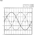
- An embodiment for estimating the electrical angle from the phase current Ip has a characteristic as shown in FIG.7 . That is, for example, when the U-phase and the V-phase are a positive value and the W-phase is a negative value, the estimating angle is estimated in the range of 0° to 60°. More finely, when the V-phase is larger than the U-phase, the estimating angle is estimated in the range of 0° to 30°.
- the estimating angle is estimated in the range of 30° to 60°.
- Other angles can be similarly estimated at a 30°-pitch from the sign of the currents and the magnitude relationship among the currents by the similar procedure.
- the torque direction judging section 221 in the ECU 200 judges the torque direction applied to the motor 100 from the moving of the pinion-side angle (Step S13). Since the estimating angle estimated at the above Step S12 is shifted by 180° when the direction of the torque applied to (generated at) the motor 100 is reversed, the direction of the torque applied to the motor 100 is estimated from the varying direction (here, the varying direction of the angle means the rotational direction) of the steering shaft angle ⁇ p being the pinion-side angle (the output shaft angle) of the column shaft, and a 180°-correction is performed if necessary.
- the steering shaft angle ⁇ p is rotated in a clock wise (CW) direction
- the brake torque is generated against the CW rotation.
- the direction of this brake torque is a reverse direction of the rotational direction
- the direction of the torque of the motor 100 is a counter clock wise (CCW) direction.
- the direction of the torque of the motor 100 is the CW direction.
- the correcting section 222 in the MCU 230 corrects the estimating electrical angle from the direction of the torque which is judged at the torque direction judging section 221 (Step S14).
- the phase current of the motor 100 has a characteristic that a polarity is reversed. That is, the sign and the magnitude relationship of the phase currents are the same in cases that the motor torque in the CW direction is occurred at the angle 90° and the motor torque in the CCW direction is occurred at the angle 270°.
- the ECU 200 releases that all of the respective phase duties are fixed to 0% (Step S15), and performs the normal assist-control by using the corrected estimating angle (Step S16).
- the duties may be fixed to 100%.
- the current detecting device such as the shunt resistor for detecting the current is disposed adjacent to the lower-stage FETs (Q2, Q4 and Q6) of the inverter 140
- the duties are fixed to 0% and all motor regenerative currents are passed through the shunt resistor.
- the current detecting device is disposed adjacent to the upper-stage FETs (Q1, Q3 and Q5) of the inverter 140, the duties are fixed to 100%.
- the angle estimating section 220 may judge the torque direction by using the sign of the steering torque Th or the sign of the differential value of the steering torque Th instead of the steering shaft angle (pinion-side angle), and the fixed time (the time which is required for the angle estimating) of the respective phase duties is changeable depending on the steering velocity, the assist torque and the like. Furthermore, the angle estimating section 220 rotates the motor by passing the current to the motor 100 in a case that the motor 100 is not rotated and an angle estimating is indefinite, and just after may perform an angle estimating by detecting the current by means of fixing the respective phase duties.
- FIG.8 shows the three-phase motor with a Y-connection.
- One system comprises the U-phase winding UW1, the V-phase winding VW1 and the W-phase winding WW1
- the other system comprises the U-phase winding UW2, the V-phase winding VW2 and the W-phase winding WW2.
- the motor is driven by passing the three-phase current through the windings UW1 to WW1 and the windings UW2 to WW2.
- FIG.9 shows the three-phase motor with a delta-connection.
- One system comprises the U-phase winding UW1, the V-phase winding VW1 and the W-phase winding WW1, and the other system comprises the U-phase winding UW2, the V-phase winding VW2 and the W-phase winding WW2.
- the motor is driven by passing the three-phase current through the windings UW1 to WW1 and the windings UW2 to WW2.
- the present invention can be also adapted to the electric power steering apparatus that is driven by the motor which has such the multi-system windings.
- FIG.10 shows a configuration example corresponding to FIG.5 .
- the driving-control of the motor 150 which has the dual-system windings with the Y-connection (L1: L1u to L1w, and L2: L2u to L2w) will be described.
- the motor controlling section that drives the motor 150 which has the dual-system motor windings comprises a control section 150A to driving-control the winding L1 (L1u to L1w), and a control section 150B to driving-control the winding L2 (L2u to L2w).
- the configuration of the control section 150A is the same as that of the control section 150B.
- the control sections 150A and 150B are controlled by the ECUs 200A and 200B, respectively.
- the ECUs 200A and 200B have the functions of at least the failure judging sections 210A and 210B, the angle estimating sections 220A and 220B, the torque direction judging sections 221A and 221B, and the correcting sections 222A and 222B, respectively.
- the steering torque Th, the vehicle speed Vs and the rotational angle ⁇ from the rotor rotational angle detecting circuit 102 are inputted into the ECUs 200A and 200B.
- the motor current I1d (Iu1, Iv1 and Iw1) detected from the respective coils of the first system motor winding L1 is inputted into the ECU 200A.
- the motor current I2d (Iu2, Iv2 and Iw2) detected from the respective coils of the second system motor winding L2 is inputted into the ECU 200B.
- a driving signal GtA of the duties which are calculated in the above manner at the ECU 200A is inputted into the gate driving circuit 130A.
- the driving signal GtB of the duties which are calculated at the ECU 200B is inputted into the gate driving circuit 130B.
- a failure signal SAa which is judged at the failure judging section 210A in the ECU 200A is inputted into the gate driving circuit 130A
- a failure signal SAb which is judged at the failure judging section 210B in the ECU 200B is inputted into the gate driving circuit 130B.
- Direct currents are supplied to the control sections 150A and 150B from the battery 105 as a DC power source through the noise filter 106 and power source blocking circuits 131A and 131B that are turned-ON or are turned-OFF by the gate driving circuits 130A and 130B, respectively.
- the power source blocking circuits 131A has a series circuit configuration that the source of the FET QC1 is connected to that of the FET QC2, and a connection direction of the parasitic diodes is opposite.
- the power source blocking circuits 131B has a series circuit configuration that the source of the FET QD1 is connected to that of the FET QD2, and the connection direction of the parasitic diodes is opposite.
- the drain of the FET QC1 is connected to that of the FET QD1 and both the drains are connected to an output side of the noise filter 106.
- the drain of the FET QC2 is connected to the sources of the FETs Q1, Q2 and Q3 of the inverter 122A.
- the drain of the FET QD2 is connected to the sources of the FETs Q1, Q2 and Q3 of the inverter 122B.
- the power-source supplying sections of the inverters 140A and 140B are connected to electrolytic capacitors CA and CB for a power source smoothing in parallel, respectively.
- a motor release relay 132A which comprises the FETs for the current blocking QA1, QA2 and QA3, is connected between the inverter 140A and the winding L1 of the motor 150.
- the motor release relay 132B which comprises the FETs for the current blocking QB1, QB2 and QB3, is connected between the inverter 140B and the winding L2 of the motor 150.
- the FETs QA1 to QA3 of the motor release relay 132A and the FETs QB1 to QB3 of the motor release relay 132B are connected to the parasitic diodes D such that the connection direction is the same by connecting the cathodes to the inverter 140A side and the inverter 140B side, respectively.
- the ECU 200A drives the winding L1 of the motor 150 through the gate driving circuit 130A and the inverter 140A based on the calculated driving signal GtA.
- the ECU 200B drives the winding L2 of the motor 150 through the gate driving circuit 130B and the inverter 140B based on the calculated driving signal GtB.
- the gate driving circuit 130A fixes the duties to 0% or 100%, and controls that the power source blocking circuit 131A and the motor release relay 132A are turned-ON or turned-OFF as needed.
- the gate driving circuit 130B fixes the duties to 0% or 100%, and controls that the power source blocking circuit 131B and the motor opening relay 132B are turned-ON or turned-OFF as needed.
- one system can be exclusively used for the driving, and the other system can be exclusively used for estimating the angle from the motor current.
- one system by fixing the duties to 0% or 100%, always detects the motor current and continues to estimate the angle, and the other system performs the assist-control by using the estimated angle. In this manner, the configuration enables to perform the angle estimating and the assist-control, simultaneously, and the driver can feel smoother steering feeling. Further, since the motor of the system fixed the duties always generates the brake torque, in the system side to perform the assist control, it is possible to cancel the change of the steering feeling each other by generating the assist torque so as to cancel the brake torque each other.
- the value of the fixed duties is not limited, the duties of the three phases are the same value, and the duties may be the value that the required current value can be measured.
Landscapes
- Engineering & Computer Science (AREA)
- Chemical & Material Sciences (AREA)
- Combustion & Propulsion (AREA)
- Transportation (AREA)
- Mechanical Engineering (AREA)
- Power Engineering (AREA)
- Steering Control In Accordance With Driving Conditions (AREA)
- Power Steering Mechanism (AREA)
- Control Of Ac Motors In General (AREA)
- Control Of Motors That Do Not Use Commutators (AREA)
Description
- The present invention relates to an electric power steering apparatus that applies an assist torque to a steering system of a vehicle by a motor by means of a current command value calculated based on at least a steering torque, and in particular to the electric power steering apparatus, for a brushless motor to be necessary to control by obtaining a motor rotational angle, that continues to assist-control by accurately estimating the motor rotational angle when an angle detecting system is failed (including an abnormality).
- An electric power steering apparatus (EPS) which provides a steering system of a vehicle with a steering assist torque (an assist torque) by a rotational torque of a motor, applies the steering assist torque to a steering shaft or a rack shaft by means of a transmission mechanism such as gears by using a driving force of the motor which is controlled by electric power supplied from an electric power supplying section (an inverter). In order to accurately generate the steering assist torque, such a conventional electric power steering apparatus performs a feed-back control of a motor current. The feed-back control adjusts a voltage supplied to the motor so that a difference between a steering assist command value (a current command value) and a detected motor current value becomes small, and the adjustment of the voltage supplied to the motor is generally performed by an adjustment of duty command values of a pulse width modulation (PWM) control.
- A general configuration of the conventional electric power steering apparatus will be described with reference to
FIG.1 . As shown inFIG.1 , a column shaft (a steering shaft or a handle shaft) 2 connected to ahandle 1 is connected to steeredwheels reduction gears 3,universal joints rack mechanism 5, andtie rods 6a and 6b, further viahub units steering shaft 2 is provided with atorque sensor 10 for detecting a steering torque Th of thehandle 1 and asteering angle sensor 14 for detecting a steering angle θ, and amotor 20 for assisting the steering torque of thehandle 1 is connected to thecolumn shaft 2 through thereduction gears 3. The electric power is supplied to a control unit (ECU) 30 for controlling the electric power steering apparatus from abattery 13, and an ignition key signal is inputted into thecontrol unit 30 through anignition key 11. Thecontrol unit 30 calculates a current command value of an assist command (a steering assist command) on the basis of the steering torque Th detected by thetorque sensor 10 and a vehicle speed Vs detected by avehicle speed sensor 12, and controls a current supplied to themotor 20 for the EPS by means of a voltage control command value Vref obtained by performing a compensation or the like to the current command value. - As well, the steering angle θ is detected from the
steering angle sensor 14, and it is possible to obtain the steering angle from a rotational sensor such as a resolver which is connected to themotor 20. - A controller area network (CAN) 40 to send/receive various information and signals on the vehicle is connected to the
control unit 100, and it is also possible to receive the vehicle speed Vel from the CAN 40. Further, a Non-CAN 41 is also possible to connect to thecontrol unit 30, and the Non-CAN 41 sends and receives a communication, analogue/digital signals, electric wave or the like except for the CAN 40. - The
control unit 30 mainly comprises a CPU (Central Processing Unit) (including an MPU (Micro Processor Unit) and an MCU (Micro Controller Unit)), and general functions performed by programs within the CPU are, for example, shown inFIG.2 . - The
control unit 30 will be described with reference toFIG.2 . As shown inFIG.2 , the steering torque Th detected by thetorque sensor 10 and the vehicle speed Vs detected by the vehicle speed sensor 12 (or from the CAN 40) are inputted into a current commandvalue calculating section 31 which calculates the current command value Iref1. The current commandvalue calculating section 31 calculates the current command value Irefl, based on the steering torque Th and the vehicle speed Vs with reference to an assist map or the like, which is a control target value of a current supplied to themotor 20. The calculated current command value Iref1 is inputted into a current limitingsection 33 via an addingsection 32A, and the current command value Irefm whose maximum current is limited is inputted into a subtractingsection 32B. A deviation I (=Irefm-Im) between the current command value Irefm and a motor current value Im which is fed-back is calculated at thesubtracting section 32B, and the deviation I is inputted into a proportional-integral-control section (PI-control section) 34 for improving a current characteristic of the steering operation. The voltage control command value Vref that the characteristic is improved at the PI-control section 34, is inputted into a PWM-control section 35, and themotor 20 is PWM-driven through aninverter 36. The current value Im of themotor 20 is detected by a motorcurrent detector 37 and is fed-back to the subtractingsection 32B. Theinverter 36 is constituted by a bridge circuit of field-effect transistors (FETs) as a semiconductor switching device. - The
rotational sensor 21 such as the resolver is connected to themotor 20 and a motor rotational angle θ is outputted. Further, a motor velocity ω is calculated at a motorvelocity calculating section 22. - Further, a compensation signal CM from a compensation
signal generating section 38 is added at the addingsection 32A. A characteristic compensation of the steering system is performed by adding the compensation signal CM, and a convergence, an inertia characteristic, and the like are improved. The compensationsignal generating section 38 adds a self-aligning torque (SAT) 38-1 to an inertia 38-2 at an adding section 38-4. The adding result is further added with a convergence 38-3 at an adding section 38-5. The adding result at the adding section 38-5 is treated as the compensation signal CM. - In a case that the
motor 20 is a three-phase brushless motor, details of the PWM-control section 35 and theinverter 36 have a configuration as shown inFIG.3 , and the PWM-control section 35 comprises aduty calculating section 35A that calculates the PWM-duty values D1 to D6 which are used in a three-phase PWM-control by using the voltage control command value Vref in accordance with a predetermined equation, and agate driving section 35B that drives gates of the FETs as the driving device by means of the PWM-duty values D1 to D6 and turns-ON or turns-OFF the gates of the FETs for compensating a dead time. Theinverter 36 is constituted by the three-phase bridge of the FETs (FET 1 to FET 6) as the semiconductor switching device, and themotor 20 is driven by turning-ON or turning-OFF the gates of the FETs with the PWM-duty values D1 to D6. Motor relays 23 for supplying (ON) the electric power or blocking off (OFF) the electric power are connected to respective phases in the electric power source lines between theinverter 36 and themotor 20. - When the motor current is not accurately controlled in the electric power steering apparatus which uses such a brushless motor, the generated torque by the motor cannot be accurately obtained. Thus, the sensor which precisely detects the motor angle is required. The resolver, a Hall sensor, a magneto resistive sensor (an MR sensor) and the like are used as the angle sensor, and any of the above sensors have a function that detects the motor angle with a required accuracy.
-
FIG.4 shows an overall configuration of an angle detecting system, and atorsion bar 2A is provided with the steering shaft (the column shaft) 2 which is connected to thehandle 1. A handle-side angle sensor 14H is disposed at thehandle 1 side of thetorsion bar 2A and a pinion-side angle sensor 14P is disposed at the pinion side of thetorsion bar 2A. Therotational sensor 21 such as the resolver is attached to themotor 20 which is provided with thesteering shaft 2 through thereduction gears 3. A pinion-side angle θp detected at the pinion-side angle sensor 14P, a motor angle θm detected from therotational sensor 21 and a motor current Im detected at a current detecting circuit are inputted into thecontrol unit 30. - However, the electric power steering apparatus using the brushless motor is used to the vehicles which have a relatively large rack thrust force due to reasons of a high motor efficiency and so on. Therefore, since it is impossible to control the motor current when the motor angle sensor is failed, there is a problem that the assist function is failed and the driver feels a quite different steering feeling relative to the steering feeling in a normal operation. Further, since the failure of the assist function means that the force assisted by the motor till then is suddenly lost, the driver receives a force, which is corresponding to the assist force of the motor, as a sudden reaction force from the handle. This causes the driver to receive an impact from the handle. In a case that the impact is in a range to be controlled by the driver, the problem is small. Reversely, in a case that the impact is out of the range to be controlled by the driver, since not only an influence to the driver, but also the influence to the vehicle behavior can be occurred, this can cause the problem of the safety.
- In this connection, the electric power steering apparatus adopting the brushless motor is strongly required to be equipped with an alternative means which can perform the angle detection even when the angle sensor of the motor is failed.
-
- Patent Document 1: Japanese Patent No.
5614598 B2 - Patent Document 2: Japanese Patent No.
5168057 B2 - Conventionally, the angle (the electrical angle) of the motor is estimated by monitoring and calculating, in the ECU, a motor back-EMF which is mainly generated when the motor is rotated. However, there are problems that it is difficult to obtain a sufficient voltage amplitude in the low speed steering region by using the motor back-EMF, the angle estimating is difficult in a steering holding state or the low speed steering state (for example, 100 [deg/s] or less) and an erroneous angle is estimated. Consequently, the angle estimating has been performed by means of complicate operations such that an operation is performed so as to generate the motor rotational number to obtain the sufficient motor back-EMF by intentionally flowing the current to the motor in order for the motor back-EMF to have the sufficient amplitude, or an operation is performed so as to measure the amplitude and the phase (the vector) of the flowing motor current by applying a high frequency voltage (200 [Hz] and the like) to stators of the motor and by utilizing an inductance difference at a d-axis and a q-axis in the vector control.
- However, the motor structure is not manufactured on the assumption that the angle estimating is performed. Thus, even when these estimating means are used, the problems that the influences of a deterioration of the estimating accuracy, the erroneous estimating and the like are significant in the low speed steering region and a state which the sufficient steering assist current is flowed, and the driver feels the quite different steering feeling compared with the normal operation of the motor angle sensor, are remained.
- The present invention has been developed in view of the above-described circumstances, and an object of the present invention is to provide the electric power steering apparatus that can perform the angle estimating by using a motor regenerative current so as to accurately perform the angle estimating even in the low speed steering.
- The present invention relates to an electric power steering apparatus that calculates a current command value based on at least a steering torque, driving-controls a motor, which applies an assist torque to a steering system based on the current command value, by an inverter with respective phase duties of a pulse width modulation (PWM), and detects an angle of the steering system or the motor, the above-described object of the present invention is achieved by that comprising: an angle estimating section to estimate the angle when a detecting system of the angle is failed, wherein the electric power steering apparatus performs an assist-control based on an estimating angle that is estimated at the angle estimating section.
- The above-described object of the present invention is efficiently achieved by that: wherein the angle estimating section fixes the respective phase duties to 0% or 100% in order to detect a regenerative current of the motor; or wherein fixed duties are 0% in a case that a motor current detecting circuit is connected to lower-stage switching devices of the inverter; or wherein fixed duties are 100% in a case that a motor current detecting circuit is connected to upper-stage switching devices of the inverter; or wherein fixed duties are selected from 0% or 100% in a case that a motor current detecting circuit is disposed on a motor phase; or wherein the angle estimating section detects a current of the motor while all of the respective phase duties are fixed; or wherein the angle estimating section estimates the angle from a detected motor current; or wherein the angle estimating section corrects an estimating angle from a rotational direction of a steering shaft angle; or wherein the angle estimating section uses a sign of the steering torque or a sign of a differential value of the steering torque instead of a rotational direction of a steering shaft angle; or wherein fixed time of the respective phase duties is changeable depending on circumstances such as a steering velocity and an assist torque; or wherein the angle estimating section drives the motor by passing a current to the motor in a circumstance that the motor is not entirely rotated and in a case that an angle estimating is indefinite, and just after performs an angle estimating by detecting a current by means of fixing the respective phase duties.
- The present invention relates to an electric power steering apparatus that calculates a current command value based on at least a steering torque, driving-controls a motor, which has dual-system windings and applies an assist torque to a steering system based on the current command value, by respective system inverters with respective phase duties of a pulse width modulation (PWM), and detects an angle of the steering system or the motor, the above-described object of the present invention is achieved by that comprising: an angle estimating section for respective systems to estimate the angle when a detecting system of the angle is failed, wherein the electric power steering apparatus performs assist-control for respective systems based on an estimating angle that is estimated at the angle estimating section.
- The above-described object of the present invention is efficiently achieved by that: wherein the angle estimating section of the respective systems fixes the respective phase duties to 0% or 100% in order to detect a regenerative current of the dual-system windings; or wherein fixed duties are 0% in a case that a motor current detecting circuit is connected to lower-stage switching devices of the respective system inverters; or wherein fixed duties are 100% in a case that a motor current detecting circuit is connected to upper-stage switching devices of the respective system inverters; or wherein fixed duties are selected from 0% or 100% in a case that a motor current detecting circuit is disposed on a motor phase; or wherein the assist-control is performed by dual-systems and one system stops the assist-control only when an angle estimating is required; or wherein a deficient assist amount while the assist-control is performed by one system and an angle estimating is performed by the other system, is compensated by increasing an assist amount of the one system which performs the assist-control; or wherein a motor release relay controls a turning-ON or a turning-OFF such that a regenerative current of a system which performs an angle estimating is not excess; or wherein a duty fixed mode and a zero ampere [A] control alternately switches with a high speed such that a regenerative current of a system which performs an angle estimating is not excess; or wherein one system which performs the assist-control generates an assist torque so as to cancel each other a brake torque that is generated from the other system which performs an angle estimating; or wherein in a case that an influence of dead times of the respective system inverters is not considered, fixed duties are not limited, three phases have a same duty and the duties have an amount to measure a required current value.
- According to the electric power steering apparatus in accordance with the present invention, since the angle estimating which uses the motor regenerative current is performed, the accurate angle estimating can be performed even in the low speed steering. Thereby, even when the angle detecting system is failed, it is possible to continue the assist-control.
- In the accompanying drawings:
-
FIG.1 is a configuration diagram showing a general outline of an electric power steering apparatus; -
FIG.2 is a block diagram showing a configuration example of a control unit (ECU) of the electric power steering apparatus; -
FIG.3 is a wiring diagram showing a configuration example of a motor control section of the electric power steering apparatus; -
FIG.4 is a schematic diagram showing an overall configuration of an angle detecting system; -
FIG.5 is a block diagram showing a configuration example of the present invention; -
FIG.6 is a flowchart showing an operation example of the present invention; -
FIG.7 is a characteristic diagram showing an example to estimate an electrical angle from phase currents; -
FIG.8 is a connection diagram showing a motor having dual-system windings (Y-connection); -
FIG.9 is a connection diagram showing the motor having dual-system windings (delta-connection); and -
FIG.10 is a block diagram showing a particular configuration example of the present invention to driving-control the motor having dual-system windings (Y-connection). - In a case that a brushless motor is used to a driving device of an electric power steering apparatus (EPS), it is necessary to obtain a motor rotational angle in order to generate an accurate motor torque. Normally, the angle is detected by using a resolver, a Hall sensor, a magneto resistive sensor (an MR sensor) and the like. Therefore, in a case that these angle detecting means are failed (including an abnormality), since the electric power steering apparatus cannot generate the accurate motor torque, there is a problem that a steering assist function which is a main function of the electric power steering apparatus cannot be continued.
- In this connection, in the present invention, even when an angle detecting system including an angle sensor is failed, an angle estimating means to estimate the angle is disposed, and a steering assist function is continued by using an estimating angle. A concrete means of the angle estimating intentionally sets to fix all of duty command values in U-phase, V-phase and W-phase to "0%" at timing when a failure of the angle sensor is occurred and an angle estimating is required. This means that: it is an object to avoid an instability state (a divergence of a yaw rate, an increase of a sudden steering torque during a turning, an occurrence of a sudden lateral acceleration and so on) of a vehicle behavior due to a changing of a sudden steering velocity by applying a damping component to a steering system by means of setting the motor to an electromagnetic brake mode, and to perform the angle estimating by accurately and immediately detecting a regenerative current, at an ECU, which is generated by rotating the motor. The above case that all phases of the duties are fixed to 0% is a case that a current detecting method is a downstream shunt method in the ECU. In a case that the current detecting method is an upstream shunt method in the ECU, it is possible to apply the damping and to detect the regenerative current by fixing the all phases of the duties to 100%. Further, in a case that the current detecting method is a phase current detecting method in the ECU, it may fix the all phases of the duties to 0% or 100%.
- When the angle estimating is completed, the all phases whose duties are fixed to 0% are released, the assist control equivalent to a normal operation is performed based on the estimated angle information instead of the angle information of the angle sensor, and the assist function is continued. Since the angle information is not obtained while the assist function is continued, the angle estimating (the duties are fixed to 0% or 100%) and the assist control alternately is repeated, and then it is possible to perform the assist control during performing the angle estimating.
- In the present invention, in order to accurately perform the angle estimating even in the low speed steering, the angle estimating by using the motor regenerative current is performed at timing when the angle detecting system is failed. This method utilizes the fact that an internal impedance (a resistance component) of the ECU and impedances (resistance components) of motor windings are sufficiently low. Normally, since the impedances of the ECU and the motor are about 10 [mΩ], it is possible to obtain a sufficient detecting current value even in the low speed steering region that the measuring is difficult as an amplitude of a motor back-EMF of the motor is too small, and to enable to accurately perform the angle estimating. In order to accurately detect the regenerative current of the motor at the ECU, it is necessary to keep all duties of the three phases to the same value. This reason is that an excessive current from the ECU to the motor is not passed and the ECU detects only the regenerative current. However, since a circuit configuration used in the normal motor driving is an inverter configuration that respective phases have two switching devices, a dead time serving as a guard time not to be short-circuited the two switching devices is set. This setting of the dead time causes a decrease in the accuracy of the current detecting. In order to prevent from a deterioration of the detecting accuracy due to the dead time, all duties of the three phases are fixed to 0% or 100%. This setting enables to eliminate the influence of the dead time.
- However, it is necessary to keep in mind that optimal fixed duties are different depending on the detecting method of the motor current. For example, in a case that the current detecting device such as a shunt resistor for detecting the current is disposed adjacent to lower-stage switching devices, the duties are fixed to 0%, and all motor regenerative currents are flowed through the shunt resistor. On the contrary, in a case that the current detecting device is disposed adjacent to upper-stage switching devices, the duties are fixed to 100%.
- Furthermore, in a case that the current detecting device is directly disposed on a motor phase between the upper-stage and the lower-stage, the duties may be fixed to 100% or 0%. By setting the above duties, even in the extremely slow steering speed (for example, 10 [deg/s] or less), it is possible to accurately detect the motor regenerative current and to estimate the electrical angle from a magnitude relationship of the three phase currents.
- Embodiments according to the present invention will be described in detail with reference to the drawings.
-
FIG.5 shows a configuration example of the present invention, and the angle detecting system is the same as that ofFIG.4 . TheECU 200 comprises a micro controller unit (MCU) 230, a stabilizedpower source circuit 201, an analog/digital (A/D) convertingsection 202 and the like. TheMCU 230 comprises functions of afailure judging section 210, anangle estimating section 220, a torquedirection judging section 221 and a correctingsection 222. TheECU 200 inputs the calculated respective phase duties into a field-effect transistor (FET)gate driving circuit 130, and drives themotor 100 via theinverter 140. Electric power is supplied from abattery 105 to theinverter 140 via aswitching section 131. Theswitching section 131 is turned-ON or turned-OFF by theECU 200. The electric power is supplied from thebattery 105 to theECU 200, and an ignition key signal from anignition key 104 is also inputted into theECU 200 and theswitching section 131. - The
resolver 101 as a rotational sensor is connected to the rotor of themotor 100. A detecting signal from theresolver 101 is inputted into a rotor rotationalangle detecting circuit 102, and the detected rotational angle θ is inputted into theECU 200. The phase currents of themotor 100 are detected at the current detectingcircuit 103, and the detected phase current Ip is inputted into theECU 200. Further, the steering torque Th that is detected by thetorque sensor 110 is converted into a digital value at the A/D converting section 202, the digital value is inputted into theMCU 230, and a vehicle speed Vs from a vehicle sensor 111 is inputted into theMCU 230. - In such a configuration, an operation example will be described with reference to a flowchart of
FIG.6 . - When the operation is started, the steering torque Th from the
torque sensor 110 and the vehicle speed Vs from the vehicle speed sensor 111 are inputted into the ECU 200 (Step S1). The ECU 200 (the MCU 230) calculates the current command value based on the steering torque Th and the vehicle speed Vs (Step S2), and calculates the respective phase duties (StepS3). Themotor 100 is driven through thegate driving circuit 130 and the inverter 140 (Step S4). In this assist control state, the phase current Ip is detected at the current detectingcircuit 103 and the rotational angle θ is detected at the rotor rotationalangle detecting circuit 102, and the detected phase current Ip and the detected rotational angle θ are respectively inputted into theECU 200. - The
failure judging section 210 in theMCU 230 judges whether the angle sensor (theresolver 101 and the like) is failed or not during performing the above assist-control (Step S5). The failure judging of the angle sensor (theresolver 101 and the like) is used to a general method that judges whether an equation "sinθ2+cosθ2=1" is satisfied or not or the like. In a case that the failure is not occurred, the operation returns to the above Step S1 and iterates the above-described steps. - At the above Step S5, in a case that the
failure judging section 210 judges that the failure is occurred at the angle sensor, the duties are fixed to 0% and the driving of themotor 100 is stopped (Step S10), and it is judged whether the amplitude of the phase current Ip detected by the current detectingcircuit 103 is a threshold Pth or more or not (Step S11). In a case that the amplitude of the phase current Ip is less than the threshold Pth, the operation returns to the above Step S10. As well, the threshold Pth is set to a value that is larger than the amplitude of the noise of the current detecting value after the A/D conversion. By reducing the noise by means of the filter process and the like, the threshold Pth which is less than the above value can be set. - At the above Step S11, in a case that it is judged that the amplitude of the phase current Ip is larger than or equal to the threshold Pth, the
angle estimating section 220 in theMCU 230 estimates the electrical angle from the phase current Ip (Step S12). An embodiment for estimating the electrical angle from the phase current Ip has a characteristic as shown inFIG.7 . That is, for example, when the U-phase and the V-phase are a positive value and the W-phase is a negative value, the estimating angle is estimated in the range of 0° to 60°. More finely, when the V-phase is larger than the U-phase, the estimating angle is estimated in the range of 0° to 30°. On the contrary, when the U-phase is larger than the V-phase, the estimating angle is estimated in the range of 30° to 60°. Other angles can be similarly estimated at a 30°-pitch from the sign of the currents and the magnitude relationship among the currents by the similar procedure. - Next, the torque
direction judging section 221 in theECU 200 judges the torque direction applied to themotor 100 from the moving of the pinion-side angle (Step S13). Since the estimating angle estimated at the above Step S12 is shifted by 180° when the direction of the torque applied to (generated at) themotor 100 is reversed, the direction of the torque applied to themotor 100 is estimated from the varying direction (here, the varying direction of the angle means the rotational direction) of the steering shaft angle θp being the pinion-side angle (the output shaft angle) of the column shaft, and a 180°-correction is performed if necessary. For example, in a case that the steering shaft angle θp is rotated in a clock wise (CW) direction, since it means that the three phases of themotor 100 are short-circuited, the brake torque is generated against the CW rotation. Then, since the direction of this brake torque is a reverse direction of the rotational direction, the direction of the torque of themotor 100 is a counter clock wise (CCW) direction. Alternatively, in a case that the steering shaft angle θp is rotated in the CCW direction, the direction of the torque of themotor 100 is the CW direction. - The correcting
section 222 in theMCU 230 corrects the estimating electrical angle from the direction of the torque which is judged at the torque direction judging section 221 (Step S14). When the direction of the torque of themotor 100 is reversed, the phase current of themotor 100 has a characteristic that a polarity is reversed. That is, the sign and the magnitude relationship of the phase currents are the same in cases that the motor torque in the CW direction is occurred at the angle 90° and the motor torque in the CCW direction is occurred at theangle 270°. Therefore, assuming that the relationship between the current and the angle, for example, as shown inFIG.7 is the case that the direction of the torque generated from themotor 100 is the CW direction, in the case that the direction of the torque of themotor 100 is the CCW direction, it is possible to obtain a right angle by correcting the estimating angle by 180°- offset correction. - As described above, when the estimation and the correction of the electrical angle are completed, the
ECU 200 releases that all of the respective phase duties are fixed to 0% (Step S15), and performs the normal assist-control by using the corrected estimating angle (Step S16). - In the above operation, although the current detecting
circuit 103 is disposed on the motor phase and the duties are fixed to 0%, the duties may be fixed to 100%. In a case that the current detecting device such as the shunt resistor for detecting the current is disposed adjacent to the lower-stage FETs (Q2, Q4 and Q6) of theinverter 140, the duties are fixed to 0% and all motor regenerative currents are passed through the shunt resistor. On the contrary, in a case that the current detecting device is disposed adjacent to the upper-stage FETs (Q1, Q3 and Q5) of theinverter 140, the duties are fixed to 100%. - Further, the
angle estimating section 220 may judge the torque direction by using the sign of the steering torque Th or the sign of the differential value of the steering torque Th instead of the steering shaft angle (pinion-side angle), and the fixed time (the time which is required for the angle estimating) of the respective phase duties is changeable depending on the steering velocity, the assist torque and the like. Furthermore, theangle estimating section 220 rotates the motor by passing the current to themotor 100 in a case that themotor 100 is not rotated and an angle estimating is indefinite, and just after may perform an angle estimating by detecting the current by means of fixing the respective phase duties. - Recently, in order to enhance the security of the motor, the motor which has the multi-system motor windings is emerged.
FIG.8 shows the three-phase motor with a Y-connection. One system comprises the U-phase winding UW1, the V-phase winding VW1 and the W-phase winding WW1, and the other system comprises the U-phase winding UW2, the V-phase winding VW2 and the W-phase winding WW2. The motor is driven by passing the three-phase current through the windings UW1 to WW1 and the windings UW2 to WW2.FIG.9 shows the three-phase motor with a delta-connection. One system comprises the U-phase winding UW1, the V-phase winding VW1 and the W-phase winding WW1, and the other system comprises the U-phase winding UW2, the V-phase winding VW2 and the W-phase winding WW2. The motor is driven by passing the three-phase current through the windings UW1 to WW1 and the windings UW2 to WW2. - The present invention can be also adapted to the electric power steering apparatus that is driven by the motor which has such the multi-system windings.
FIG.10 shows a configuration example corresponding toFIG.5 . In the present embodiment, the driving-control of themotor 150 which has the dual-system windings with the Y-connection (L1: L1u to L1w, and L2: L2u to L2w) will be described. - The motor controlling section that drives the
motor 150 which has the dual-system motor windings, comprises acontrol section 150A to driving-control the winding L1 (L1u to L1w), and acontrol section 150B to driving-control the winding L2 (L2u to L2w). The configuration of thecontrol section 150A is the same as that of thecontrol section 150B. Thecontrol sections ECUs ECUs failure judging sections angle estimating sections direction judging sections sections - The steering torque Th, the vehicle speed Vs and the rotational angle θ from the rotor rotational
angle detecting circuit 102 are inputted into theECUs ECU 200A. The motor current I2d (Iu2, Iv2 and Iw2) detected from the respective coils of the second system motor winding L2 is inputted into theECU 200B. A driving signal GtA of the duties which are calculated in the above manner at theECU 200A is inputted into thegate driving circuit 130A. The driving signal GtB of the duties which are calculated at theECU 200B is inputted into thegate driving circuit 130B. Further, a failure signal SAa which is judged at thefailure judging section 210A in theECU 200A is inputted into thegate driving circuit 130A, and a failure signal SAb which is judged at thefailure judging section 210B in theECU 200B is inputted into thegate driving circuit 130B. - Direct currents (DC) are supplied to the
control sections battery 105 as a DC power source through thenoise filter 106 and powersource blocking circuits 131A and 131B that are turned-ON or are turned-OFF by thegate driving circuits source blocking circuits 131A has a series circuit configuration that the source of the FET QC1 is connected to that of the FET QC2, and a connection direction of the parasitic diodes is opposite. The power source blocking circuits 131B has a series circuit configuration that the source of the FET QD1 is connected to that of the FET QD2, and the connection direction of the parasitic diodes is opposite. The drain of the FET QC1 is connected to that of the FET QD1 and both the drains are connected to an output side of thenoise filter 106. The drain of the FET QC2 is connected to the sources of the FETs Q1, Q2 and Q3 of the inverter 122A. The drain of the FET QD2 is connected to the sources of the FETs Q1, Q2 and Q3 of the inverter 122B. - The power-source supplying sections of the
inverters motor release relay 132A, which comprises the FETs for the current blocking QA1, QA2 and QA3, is connected between theinverter 140A and the winding L1 of themotor 150. Themotor release relay 132B, which comprises the FETs for the current blocking QB1, QB2 and QB3, is connected between theinverter 140B and the winding L2 of themotor 150. The FETs QA1 to QA3 of themotor release relay 132A and the FETs QB1 to QB3 of themotor release relay 132B are connected to the parasitic diodes D such that the connection direction is the same by connecting the cathodes to theinverter 140A side and theinverter 140B side, respectively. - When the failure of the angle detecting system is not judged and the failure signal SAa is not outputted, the
ECU 200A drives the winding L1 of themotor 150 through thegate driving circuit 130A and theinverter 140A based on the calculated driving signal GtA. When the failure of the angle detecting system is not judged and the failure signal SAb is not outputted, theECU 200B drives the winding L2 of themotor 150 through thegate driving circuit 130B and theinverter 140B based on the calculated driving signal GtB. Then, when the failure signal SAa is inputted from theECU 200A to thegate driving circuit 130A, thegate driving circuit 130A fixes the duties to 0% or 100%, and controls that the powersource blocking circuit 131A and themotor release relay 132A are turned-ON or turned-OFF as needed. When the failure signal SAb is inputted from theECU 200B to thegate driving circuit 130B, thegate driving circuit 130B fixes the duties to 0% or 100%, and controls that the power source blocking circuit 131B and themotor opening relay 132B are turned-ON or turned-OFF as needed. - In a case of such a dual-system hardware configuration, one system can be exclusively used for the driving, and the other system can be exclusively used for estimating the angle from the motor current. Concretely, one system, by fixing the duties to 0% or 100%, always detects the motor current and continues to estimate the angle, and the other system performs the assist-control by using the estimated angle. In this manner, the configuration enables to perform the angle estimating and the assist-control, simultaneously, and the driver can feel smoother steering feeling. Further, since the motor of the system fixed the duties always generates the brake torque, in the system side to perform the assist control, it is possible to cancel the change of the steering feeling each other by generating the assist torque so as to cancel the brake torque each other. In addition, in order to avoid the deficiency of the assist and unnecessary viscous feeling due to the excess brake torque, it is also possible to control the steering by turning-ON or turning-OFF the motor release relay of the system fixed the duties so as not be the excess brake torque. Or, a similar effect can be obtained by fast and alternately switching between the duty fixed mode and the 0-ampere [A] control.
- In a case of not considering the influence of the dead time of the inverters of the respective systems, the value of the fixed duties is not limited, the duties of the three phases are the same value, and the duties may be the value that the required current value can be measured.
-
- 1
- handle
- 2A
- torsion bar
- 2
- column shaft (steering shaft, handle shaft)
- 10, 110
- torque sensor
- 12, 111
- vehicle speed sensor
- 14H
- handle-side angle sensor
- 14P
- pinion-side angle sensor
- 20, 100, 150
- motor
- 23
- motor release switch
- 30, 200
- control unit (ECU)
- 31
- current command value calculating section
- 34
- proportional-integral (PI) control section
- 35
- pulse width modulation (PWM) control section
- 36, 140
- inverter
- 101
- resolver
- 102
- rotor rotational angle detecting circuit
- 103
- current detecting circuit
- 130
- field-effect transistor (FET) gate driving circuit
- 210
- failure judging section
- 220
- angle estimating section
- 221
- torque direction judging section
- 222
- correcting section
- 230
- MCU
Claims (22)
- An electric power steering apparatus that calculates a current command value based on at least a steering torque, driving-controls a motor, which applies an assist torque to a steering system based on said current command value, by an inverter with respective phase duties of a pulse width modulation (PWM), and detects an angle of said steering system or said motor, comprising:an angle estimating section to estimate said angle when a detecting system of said angle is failed,wherein said electric power steering apparatus performs an assist-control based on an estimating angle that is estimated at said angle estimating section.
- The electric power steering apparatus according to Claim 1, wherein said angle estimating section fixes said respective phase duties to 0% or 100% in order to detect a regenerative current of said motor.
- The electric power steering apparatus according to Claim 2, wherein fixed duties are 0% in a case that a motor current detecting circuit is connected to lower-stage switching devices of said inverter.
- The electric power steering apparatus according to Claim 2, wherein fixed duties are 100% in a case that a motor current detecting circuit is connected to upper-stage switching devices of said inverter.
- The electric power steering apparatus according to Claim 2, wherein fixed duties are selected from 0% or 100% in a case that a motor current detecting circuit is disposed on a motor phase.
- The electric power steering apparatus according to any one of Claims 1 to 5, wherein said angle estimating section detects a current of said motor while all of said respective phase duties are fixed.
- The electric power steering apparatus according to Claim 6, wherein said angle estimating section estimates said angle from a detected motor current.
- The electric power steering apparatus according to any one of Claims 1 to 7, wherein said angle estimating section corrects an estimating angle from a rotational direction of a steering shaft angle.
- The electric power steering apparatus according to any one of Claims 1 to 7, wherein said angle estimating section uses a sign of said steering torque or a sign of a differential value of said steering torque instead of a rotational direction of a steering shaft angle.
- The electric power steering apparatus according to any one of Claims 1 to 9, wherein a fixed time of said respective phase duties is changeable depending on circumstances such as a steering velocity and an assist torque.
- The electric power steering apparatus according to any one of Claims 6 to 9, wherein said angle estimating section drives said motor by passing a current to said motor in a circumstance that said motor is not entirely rotated and in a case that an angle estimating is indefinite, and just after performs an angle estimating by detecting a current by means of fixing said respective phase duties.
- An electric power steering apparatus that calculates a current command value based on at least a steering torque, driving-controls a motor, which has dual-system windings and applies an assist torque to a steering system based on said current command value, by respective system inverters with respective phase duties of a pulse width modulation (PWM), and detects an angle of said steering system or said motor, comprising:an angle estimating section for respective systems to estimate said angle when a detecting system of said angle is failed,wherein said electric power steering apparatus performs an assist-control for respective systems based on an estimating angle that is estimated at said angle estimating section.
- The electric power steering apparatus according to Claim 12, wherein said angle estimating section of said respective systems fixes said respective phase duties to 0% or 100% in order to detect a regenerative current of said dual-system windings.
- The electric power steering apparatus according to Claim 12 or 13, wherein fixed duties are 0% in a case that a motor current detecting circuit is connected to lower-stage switching devices of said respective system inverters.
- The electric power steering apparatus according to Claim 12 or 13, wherein fixed duties are 100% in a case that a motor current detecting circuit is connected to upper-stage switching devices of said respective system inverters.
- The electric power steering apparatus according to Claim 12 or 13, wherein fixed duties are selected from 0% or 100% in a case that a motor current detecting circuit is disposed on a motor phase.
- The electric power steering apparatus according to any one of Claims 12 to 16, wherein said assist-control is performed by dual-systems and one system stops said assist-control only when an angle estimating is required.
- The electric power steering apparatus according to any one of Claims 12 to 16, wherein a deficient assist amount while said assist-control is performed by one system and an angle estimating is performed by other system, is compensated by increasing an assist amount of said one system which performs said assist-control.
- The electric power steering apparatus according to any one of Claims 12 to 18, wherein a motor release relay controls a turning-ON or a turning-OFF such that a regenerative current of a system which performs an angle estimating is not excess.
- The electric power steering apparatus according to any one of Claims 12 to 18, wherein a duty fixed mode and a zero ampere [A] control alternately switches with a high speed such that a regenerative current of a system which performs an angle estimating is not excess.
- The electric power steering apparatus according to any one of Claims 12 to 16, wherein one system which performs said assist-control generates an assist torque so as to cancel each other a brake torque that is generated from the other system which performs an angle estimating.
- The electric power steering apparatus according to Claim 21, wherein in a case that an influence of dead times of said respective system inverters is not considered, fixed duties are not limited, three phases have a same duty and said duties have an amount to measure a required current value.
Applications Claiming Priority (3)
| Application Number | Priority Date | Filing Date | Title |
|---|---|---|---|
| JP2015185871 | 2015-09-18 | ||
| JP2016010958 | 2016-01-22 | ||
| PCT/JP2016/077311 WO2017047708A1 (en) | 2015-09-18 | 2016-09-15 | Electric power steering device |
Publications (3)
| Publication Number | Publication Date |
|---|---|
| EP3351456A1 true EP3351456A1 (en) | 2018-07-25 |
| EP3351456A4 EP3351456A4 (en) | 2018-11-21 |
| EP3351456B1 EP3351456B1 (en) | 2020-03-04 |
Family
ID=58289370
Family Applications (1)
| Application Number | Title | Priority Date | Filing Date |
|---|---|---|---|
| EP16846579.7A Active EP3351456B1 (en) | 2015-09-18 | 2016-09-15 | Electric power steering device |
Country Status (7)
| Country | Link |
|---|---|
| US (1) | US10286949B2 (en) |
| EP (1) | EP3351456B1 (en) |
| JP (5) | JP6281665B2 (en) |
| KR (1) | KR101885842B1 (en) |
| CN (1) | CN107922001B (en) |
| BR (1) | BR112018013744A2 (en) |
| WO (1) | WO2017047708A1 (en) |
Cited By (1)
| Publication number | Priority date | Publication date | Assignee | Title |
|---|---|---|---|---|
| EP3483036A1 (en) * | 2017-11-09 | 2019-05-15 | Jtekt Corporation | Steering control apparatus |
Families Citing this family (16)
| Publication number | Priority date | Publication date | Assignee | Title |
|---|---|---|---|---|
| JP6944657B2 (en) * | 2017-09-14 | 2021-10-06 | 日本精工株式会社 | Motor control device and electric power steering device equipped with it |
| US11267528B2 (en) | 2017-10-20 | 2022-03-08 | Shimano Inc. | Bicycle device and brake system |
| JP6922669B2 (en) * | 2017-11-07 | 2021-08-18 | 株式会社ジェイテクト | Steering control device |
| JP6988492B2 (en) * | 2018-01-11 | 2022-01-05 | 株式会社デンソー | Electric power steering device |
| KR102631269B1 (en) * | 2019-04-03 | 2024-01-30 | 에이치엘만도 주식회사 | Apparatus for controlling motor for electronic power steering and method thereof |
| CN110104058B (en) * | 2019-04-26 | 2024-06-11 | 淮阴工学院 | An automobile power steering system based on electromagnetic linear actuator |
| US11485407B2 (en) | 2019-05-16 | 2022-11-01 | Lightning Systems, Inc. | Smart electronic power steering system and method for a retrofitted electric vehicle |
| JP7211515B2 (en) * | 2020-02-13 | 2023-01-24 | 日本精工株式会社 | Phase adjustment method, correction value calculation device, motor control device, electric actuator product, and electric power steering device |
| JP7540920B2 (en) * | 2020-09-07 | 2024-08-27 | 株式会社ジェイテクト | Motor control device |
| JP7565788B2 (en) | 2020-12-23 | 2024-10-11 | 富士フイルム株式会社 | Magnetic tape device, magnetic tape and magnetic tape cartridge |
| BR112023025760A2 (en) * | 2021-06-28 | 2024-02-27 | Jfe Steel Corp | METHOD FOR ESTIMATION OF AMOUNT OF HEAT SUPPLIES, DEVICE FOR ESTIMATION OF AMOUNT OF HEAT SUPPLIES, PROGRAM FOR ESTIMATION OF AMOUNT OF HEAT SUPPLIES AND METHOD OF OPERATION OF BLAST FURNACE |
| WO2023275914A1 (en) | 2021-06-28 | 2023-01-05 | 三菱電機株式会社 | Autonomous driving assistance device |
| JP7586008B2 (en) * | 2021-07-14 | 2024-11-19 | 株式会社デンソー | Motor Control Device |
| KR102634428B1 (en) * | 2021-12-27 | 2024-02-06 | 디와이씨스 주식회사 | Motor control method and apparatus |
| JP7721016B2 (en) * | 2022-11-01 | 2025-08-08 | 三菱電機モビリティ株式会社 | Electric power steering device |
| KR102888522B1 (en) * | 2025-08-12 | 2025-11-24 | 주식회사 이에스피 | Vehicle steering control device based on dc motor torque control for driving safety |
Family Cites Families (29)
| Publication number | Priority date | Publication date | Assignee | Title |
|---|---|---|---|---|
| JPS5168057A (en) | 1974-12-10 | 1976-06-12 | Mitsubishi Electric Corp | Erebeetano senpatsukagoshiteisochi |
| JPS5822078B2 (en) | 1979-07-17 | 1983-05-06 | 旭化成株式会社 | Advanced refining method for wool wax |
| JP2722750B2 (en) | 1990-02-14 | 1998-03-09 | 松下電器産業株式会社 | Drive device for brushless motor |
| JP3381408B2 (en) * | 1993-10-26 | 2003-02-24 | トヨタ自動車株式会社 | Electric angle detecting device and synchronous motor driving device using the same |
| JP3636340B2 (en) | 1997-06-30 | 2005-04-06 | 富士電機機器制御株式会社 | Power converter for AC rotating machine |
| JP3353664B2 (en) * | 1997-07-30 | 2002-12-03 | トヨタ自動車株式会社 | Electrical angle detector |
| JP3598909B2 (en) * | 1998-09-30 | 2004-12-08 | 株式会社日立製作所 | Synchronous motor control device, electric vehicle control device, and synchronous motor control method |
| US6979975B1 (en) | 2000-03-27 | 2005-12-27 | Mitsubishi Denki Kabushiki Kaisha | Rotation state detecting apparatus of a synchronous machine |
| JP4269686B2 (en) | 2003-01-09 | 2009-05-27 | 株式会社明電舎 | Sensorless measurement method and position sensorless variable speed device for synchronous motor position, speed and voltage amplitude |
| JP4103051B2 (en) | 2003-11-28 | 2008-06-18 | 富士電機機器制御株式会社 | Power converter for AC motor |
| JP3981102B2 (en) | 2004-06-08 | 2007-09-26 | 本田技研工業株式会社 | Motor drive circuit and electric power steering device |
| JP2007174721A (en) * | 2005-12-19 | 2007-07-05 | Mitsubishi Heavy Ind Ltd | Apparatus and method for detecting initial rotational position in brushless dc motor |
| JP4858006B2 (en) | 2006-08-23 | 2012-01-18 | 日本精工株式会社 | Electric power steering control device |
| JP5012258B2 (en) | 2006-09-07 | 2012-08-29 | 日本精工株式会社 | Electric power steering device |
| JP5174596B2 (en) * | 2008-09-18 | 2013-04-03 | 三菱電機株式会社 | Electric power steering device |
| JP5168057B2 (en) | 2008-09-29 | 2013-03-21 | 日本精工株式会社 | Electric power steering device |
| JP2011010401A (en) * | 2009-06-24 | 2011-01-13 | Jtekt Corp | Motor controller and motor-driven power steering device |
| JP5263079B2 (en) | 2009-08-26 | 2013-08-14 | トヨタ自動車株式会社 | Electric power steering device |
| JP4831503B2 (en) * | 2009-09-30 | 2011-12-07 | 株式会社デンソー | Control device for multi-phase rotating machine and electric power steering device using the same |
| JP5433657B2 (en) * | 2011-09-15 | 2014-03-05 | 株式会社東芝 | Motor control device |
| JP5449429B2 (en) * | 2012-02-24 | 2014-03-19 | 三菱電機株式会社 | AC rotating machine control device and method, and electric power steering device |
| JP5502126B2 (en) | 2012-03-26 | 2014-05-28 | 三菱電機株式会社 | Drive device for multi-winding rotating machine |
| JP5897450B2 (en) | 2012-10-25 | 2016-03-30 | 株式会社クボタ | Motor control device |
| JP5614598B2 (en) | 2012-12-26 | 2014-10-29 | 株式会社ジェイテクト | Motor control device |
| JP6022951B2 (en) * | 2013-01-18 | 2016-11-09 | トヨタ自動車株式会社 | Electric power steering device |
| WO2014126563A1 (en) * | 2013-02-14 | 2014-08-21 | Otis Elevator Company | Elevator car speed control in a battery powered elevator system |
| JP2015039256A (en) | 2013-03-15 | 2015-02-26 | 日本精工株式会社 | Motor control device, electric power steering device using the same, and vehicle |
| JP6129677B2 (en) | 2013-08-05 | 2017-05-17 | 日立オートモティブシステムズ株式会社 | Electric motor drive control device |
| JP6108043B2 (en) * | 2014-09-04 | 2017-04-05 | 日本精工株式会社 | Motor control device, failure detection method, electric power steering device equipped with them, and vehicle |
-
2016
- 2016-09-15 CN CN201680048717.0A patent/CN107922001B/en active Active
- 2016-09-15 US US15/751,315 patent/US10286949B2/en active Active
- 2016-09-15 WO PCT/JP2016/077311 patent/WO2017047708A1/en not_active Ceased
- 2016-09-15 BR BR112018013744A patent/BR112018013744A2/en unknown
- 2016-09-15 EP EP16846579.7A patent/EP3351456B1/en active Active
- 2016-09-15 KR KR1020187007173A patent/KR101885842B1/en not_active Expired - Fee Related
- 2016-09-15 JP JP2017539976A patent/JP6281665B2/en active Active
-
2018
- 2018-01-23 JP JP2018008990A patent/JP6635129B2/en active Active
- 2018-01-23 JP JP2018008988A patent/JP6635127B2/en active Active
- 2018-01-23 JP JP2018008987A patent/JP6624213B2/en active Active
- 2018-01-23 JP JP2018008989A patent/JP6635128B2/en active Active
Cited By (1)
| Publication number | Priority date | Publication date | Assignee | Title |
|---|---|---|---|---|
| EP3483036A1 (en) * | 2017-11-09 | 2019-05-15 | Jtekt Corporation | Steering control apparatus |
Also Published As
| Publication number | Publication date |
|---|---|
| JP6624213B2 (en) | 2019-12-25 |
| JP2018088809A (en) | 2018-06-07 |
| CN107922001A (en) | 2018-04-17 |
| JP6281665B2 (en) | 2018-02-21 |
| EP3351456B1 (en) | 2020-03-04 |
| WO2017047708A1 (en) | 2017-03-23 |
| KR101885842B1 (en) | 2018-08-06 |
| JP2018088810A (en) | 2018-06-07 |
| KR20180032656A (en) | 2018-03-30 |
| BR112018013744A2 (en) | 2019-02-05 |
| US20180229764A1 (en) | 2018-08-16 |
| CN107922001B (en) | 2020-10-27 |
| JPWO2017047708A1 (en) | 2018-04-19 |
| US10286949B2 (en) | 2019-05-14 |
| JP2018088808A (en) | 2018-06-07 |
| JP2018088807A (en) | 2018-06-07 |
| JP6635129B2 (en) | 2020-01-22 |
| JP6635127B2 (en) | 2020-01-22 |
| JP6635128B2 (en) | 2020-01-22 |
| EP3351456A4 (en) | 2018-11-21 |
Similar Documents
| Publication | Publication Date | Title |
|---|---|---|
| EP3351456B1 (en) | Electric power steering device | |
| EP3113355B1 (en) | Motor control device and electric power-steering device and vehicle using said motor control device | |
| US7141948B2 (en) | Electromotive power steering system | |
| US8710775B2 (en) | Electric power steering apparatus | |
| US10300940B2 (en) | Electric power steering apparatus | |
| US9248852B2 (en) | Electric power steering system | |
| EP3219579A1 (en) | Motor control device and steering control device | |
| EP3020615B1 (en) | Electric power steering device | |
| US9906174B2 (en) | Power steering device and control device for power steering device | |
| EP3171507A1 (en) | Motor control device, electric power steering device mounted with same, and vehicle | |
| US8981690B2 (en) | Electric power steering system | |
| JP2016096608A (en) | Motor control device, electric power steering device using the same, and vehicle | |
| JP6641908B2 (en) | Motor control device, motor control method, motor control program, electric motor, electric power steering device, and vehicle |
Legal Events
| Date | Code | Title | Description |
|---|---|---|---|
| STAA | Information on the status of an ep patent application or granted ep patent |
Free format text: STATUS: THE INTERNATIONAL PUBLICATION HAS BEEN MADE |
|
| PUAI | Public reference made under article 153(3) epc to a published international application that has entered the european phase |
Free format text: ORIGINAL CODE: 0009012 |
|
| STAA | Information on the status of an ep patent application or granted ep patent |
Free format text: STATUS: REQUEST FOR EXAMINATION WAS MADE |
|
| 17P | Request for examination filed |
Effective date: 20180215 |
|
| AK | Designated contracting states |
Kind code of ref document: A1 Designated state(s): AL AT BE BG CH CY CZ DE DK EE ES FI FR GB GR HR HU IE IS IT LI LT LU LV MC MK MT NL NO PL PT RO RS SE SI SK SM TR |
|
| AX | Request for extension of the european patent |
Extension state: BA ME |
|
| REG | Reference to a national code |
Ref country code: DE Ref legal event code: R079 Ref document number: 602016031265 Country of ref document: DE Free format text: PREVIOUS MAIN CLASS: B62D0006000000 Ipc: B62D0005040000 |
|
| A4 | Supplementary search report drawn up and despatched |
Effective date: 20181024 |
|
| RIC1 | Information provided on ipc code assigned before grant |
Ipc: B62D 113/00 20060101ALI20181018BHEP Ipc: H02P 6/18 20160101ALI20181018BHEP Ipc: H02P 29/028 20160101ALI20181018BHEP Ipc: B62D 5/04 20060101AFI20181018BHEP |
|
| DAV | Request for validation of the european patent (deleted) | ||
| DAX | Request for extension of the european patent (deleted) | ||
| GRAP | Despatch of communication of intention to grant a patent |
Free format text: ORIGINAL CODE: EPIDOSNIGR1 |
|
| STAA | Information on the status of an ep patent application or granted ep patent |
Free format text: STATUS: GRANT OF PATENT IS INTENDED |
|
| INTG | Intention to grant announced |
Effective date: 20190823 |
|
| GRAS | Grant fee paid |
Free format text: ORIGINAL CODE: EPIDOSNIGR3 |
|
| GRAA | (expected) grant |
Free format text: ORIGINAL CODE: 0009210 |
|
| STAA | Information on the status of an ep patent application or granted ep patent |
Free format text: STATUS: THE PATENT HAS BEEN GRANTED |
|
| AK | Designated contracting states |
Kind code of ref document: B1 Designated state(s): AL AT BE BG CH CY CZ DE DK EE ES FI FR GB GR HR HU IE IS IT LI LT LU LV MC MK MT NL NO PL PT RO RS SE SI SK SM TR |
|
| REG | Reference to a national code |
Ref country code: GB Ref legal event code: FG4D |
|
| REG | Reference to a national code |
Ref country code: CH Ref legal event code: EP |
|
| REG | Reference to a national code |
Ref country code: AT Ref legal event code: REF Ref document number: 1240050 Country of ref document: AT Kind code of ref document: T Effective date: 20200315 |
|
| REG | Reference to a national code |
Ref country code: DE Ref legal event code: R096 Ref document number: 602016031265 Country of ref document: DE |
|
| REG | Reference to a national code |
Ref country code: IE Ref legal event code: FG4D |
|
| PG25 | Lapsed in a contracting state [announced via postgrant information from national office to epo] |
Ref country code: RS Free format text: LAPSE BECAUSE OF FAILURE TO SUBMIT A TRANSLATION OF THE DESCRIPTION OR TO PAY THE FEE WITHIN THE PRESCRIBED TIME-LIMIT Effective date: 20200304 Ref country code: FI Free format text: LAPSE BECAUSE OF FAILURE TO SUBMIT A TRANSLATION OF THE DESCRIPTION OR TO PAY THE FEE WITHIN THE PRESCRIBED TIME-LIMIT Effective date: 20200304 Ref country code: NO Free format text: LAPSE BECAUSE OF FAILURE TO SUBMIT A TRANSLATION OF THE DESCRIPTION OR TO PAY THE FEE WITHIN THE PRESCRIBED TIME-LIMIT Effective date: 20200604 |
|
| REG | Reference to a national code |
Ref country code: NL Ref legal event code: MP Effective date: 20200304 |
|
| PG25 | Lapsed in a contracting state [announced via postgrant information from national office to epo] |
Ref country code: SE Free format text: LAPSE BECAUSE OF FAILURE TO SUBMIT A TRANSLATION OF THE DESCRIPTION OR TO PAY THE FEE WITHIN THE PRESCRIBED TIME-LIMIT Effective date: 20200304 Ref country code: LV Free format text: LAPSE BECAUSE OF FAILURE TO SUBMIT A TRANSLATION OF THE DESCRIPTION OR TO PAY THE FEE WITHIN THE PRESCRIBED TIME-LIMIT Effective date: 20200304 Ref country code: HR Free format text: LAPSE BECAUSE OF FAILURE TO SUBMIT A TRANSLATION OF THE DESCRIPTION OR TO PAY THE FEE WITHIN THE PRESCRIBED TIME-LIMIT Effective date: 20200304 Ref country code: BG Free format text: LAPSE BECAUSE OF FAILURE TO SUBMIT A TRANSLATION OF THE DESCRIPTION OR TO PAY THE FEE WITHIN THE PRESCRIBED TIME-LIMIT Effective date: 20200604 Ref country code: GR Free format text: LAPSE BECAUSE OF FAILURE TO SUBMIT A TRANSLATION OF THE DESCRIPTION OR TO PAY THE FEE WITHIN THE PRESCRIBED TIME-LIMIT Effective date: 20200605 |
|
| REG | Reference to a national code |
Ref country code: LT Ref legal event code: MG4D |
|
| PG25 | Lapsed in a contracting state [announced via postgrant information from national office to epo] |
Ref country code: NL Free format text: LAPSE BECAUSE OF FAILURE TO SUBMIT A TRANSLATION OF THE DESCRIPTION OR TO PAY THE FEE WITHIN THE PRESCRIBED TIME-LIMIT Effective date: 20200304 |
|
| PG25 | Lapsed in a contracting state [announced via postgrant information from national office to epo] |
Ref country code: RO Free format text: LAPSE BECAUSE OF FAILURE TO SUBMIT A TRANSLATION OF THE DESCRIPTION OR TO PAY THE FEE WITHIN THE PRESCRIBED TIME-LIMIT Effective date: 20200304 Ref country code: IS Free format text: LAPSE BECAUSE OF FAILURE TO SUBMIT A TRANSLATION OF THE DESCRIPTION OR TO PAY THE FEE WITHIN THE PRESCRIBED TIME-LIMIT Effective date: 20200704 Ref country code: SK Free format text: LAPSE BECAUSE OF FAILURE TO SUBMIT A TRANSLATION OF THE DESCRIPTION OR TO PAY THE FEE WITHIN THE PRESCRIBED TIME-LIMIT Effective date: 20200304 Ref country code: CZ Free format text: LAPSE BECAUSE OF FAILURE TO SUBMIT A TRANSLATION OF THE DESCRIPTION OR TO PAY THE FEE WITHIN THE PRESCRIBED TIME-LIMIT Effective date: 20200304 Ref country code: SM Free format text: LAPSE BECAUSE OF FAILURE TO SUBMIT A TRANSLATION OF THE DESCRIPTION OR TO PAY THE FEE WITHIN THE PRESCRIBED TIME-LIMIT Effective date: 20200304 Ref country code: PT Free format text: LAPSE BECAUSE OF FAILURE TO SUBMIT A TRANSLATION OF THE DESCRIPTION OR TO PAY THE FEE WITHIN THE PRESCRIBED TIME-LIMIT Effective date: 20200729 Ref country code: EE Free format text: LAPSE BECAUSE OF FAILURE TO SUBMIT A TRANSLATION OF THE DESCRIPTION OR TO PAY THE FEE WITHIN THE PRESCRIBED TIME-LIMIT Effective date: 20200304 Ref country code: ES Free format text: LAPSE BECAUSE OF FAILURE TO SUBMIT A TRANSLATION OF THE DESCRIPTION OR TO PAY THE FEE WITHIN THE PRESCRIBED TIME-LIMIT Effective date: 20200304 Ref country code: LT Free format text: LAPSE BECAUSE OF FAILURE TO SUBMIT A TRANSLATION OF THE DESCRIPTION OR TO PAY THE FEE WITHIN THE PRESCRIBED TIME-LIMIT Effective date: 20200304 |
|
| REG | Reference to a national code |
Ref country code: AT Ref legal event code: MK05 Ref document number: 1240050 Country of ref document: AT Kind code of ref document: T Effective date: 20200304 |
|
| REG | Reference to a national code |
Ref country code: DE Ref legal event code: R097 Ref document number: 602016031265 Country of ref document: DE |
|
| PLBE | No opposition filed within time limit |
Free format text: ORIGINAL CODE: 0009261 |
|
| STAA | Information on the status of an ep patent application or granted ep patent |
Free format text: STATUS: NO OPPOSITION FILED WITHIN TIME LIMIT |
|
| PG25 | Lapsed in a contracting state [announced via postgrant information from national office to epo] |
Ref country code: AT Free format text: LAPSE BECAUSE OF FAILURE TO SUBMIT A TRANSLATION OF THE DESCRIPTION OR TO PAY THE FEE WITHIN THE PRESCRIBED TIME-LIMIT Effective date: 20200304 Ref country code: DK Free format text: LAPSE BECAUSE OF FAILURE TO SUBMIT A TRANSLATION OF THE DESCRIPTION OR TO PAY THE FEE WITHIN THE PRESCRIBED TIME-LIMIT Effective date: 20200304 Ref country code: IT Free format text: LAPSE BECAUSE OF FAILURE TO SUBMIT A TRANSLATION OF THE DESCRIPTION OR TO PAY THE FEE WITHIN THE PRESCRIBED TIME-LIMIT Effective date: 20200304 |
|
| 26N | No opposition filed |
Effective date: 20201207 |
|
| PG25 | Lapsed in a contracting state [announced via postgrant information from national office to epo] |
Ref country code: PL Free format text: LAPSE BECAUSE OF FAILURE TO SUBMIT A TRANSLATION OF THE DESCRIPTION OR TO PAY THE FEE WITHIN THE PRESCRIBED TIME-LIMIT Effective date: 20200304 Ref country code: SI Free format text: LAPSE BECAUSE OF FAILURE TO SUBMIT A TRANSLATION OF THE DESCRIPTION OR TO PAY THE FEE WITHIN THE PRESCRIBED TIME-LIMIT Effective date: 20200304 |
|
| REG | Reference to a national code |
Ref country code: CH Ref legal event code: PL |
|
| GBPC | Gb: european patent ceased through non-payment of renewal fee |
Effective date: 20200915 |
|
| REG | Reference to a national code |
Ref country code: BE Ref legal event code: MM Effective date: 20200930 |
|
| PG25 | Lapsed in a contracting state [announced via postgrant information from national office to epo] |
Ref country code: LU Free format text: LAPSE BECAUSE OF NON-PAYMENT OF DUE FEES Effective date: 20200915 |
|
| PG25 | Lapsed in a contracting state [announced via postgrant information from national office to epo] |
Ref country code: FR Free format text: LAPSE BECAUSE OF NON-PAYMENT OF DUE FEES Effective date: 20200930 |
|
| PG25 | Lapsed in a contracting state [announced via postgrant information from national office to epo] |
Ref country code: BE Free format text: LAPSE BECAUSE OF NON-PAYMENT OF DUE FEES Effective date: 20200930 Ref country code: CH Free format text: LAPSE BECAUSE OF NON-PAYMENT OF DUE FEES Effective date: 20200930 Ref country code: LI Free format text: LAPSE BECAUSE OF NON-PAYMENT OF DUE FEES Effective date: 20200930 Ref country code: IE Free format text: LAPSE BECAUSE OF NON-PAYMENT OF DUE FEES Effective date: 20200915 Ref country code: GB Free format text: LAPSE BECAUSE OF NON-PAYMENT OF DUE FEES Effective date: 20200915 |
|
| PG25 | Lapsed in a contracting state [announced via postgrant information from national office to epo] |
Ref country code: TR Free format text: LAPSE BECAUSE OF FAILURE TO SUBMIT A TRANSLATION OF THE DESCRIPTION OR TO PAY THE FEE WITHIN THE PRESCRIBED TIME-LIMIT Effective date: 20200304 Ref country code: MT Free format text: LAPSE BECAUSE OF FAILURE TO SUBMIT A TRANSLATION OF THE DESCRIPTION OR TO PAY THE FEE WITHIN THE PRESCRIBED TIME-LIMIT Effective date: 20200304 Ref country code: CY Free format text: LAPSE BECAUSE OF FAILURE TO SUBMIT A TRANSLATION OF THE DESCRIPTION OR TO PAY THE FEE WITHIN THE PRESCRIBED TIME-LIMIT Effective date: 20200304 |
|
| PG25 | Lapsed in a contracting state [announced via postgrant information from national office to epo] |
Ref country code: MK Free format text: LAPSE BECAUSE OF FAILURE TO SUBMIT A TRANSLATION OF THE DESCRIPTION OR TO PAY THE FEE WITHIN THE PRESCRIBED TIME-LIMIT Effective date: 20200304 Ref country code: MC Free format text: LAPSE BECAUSE OF FAILURE TO SUBMIT A TRANSLATION OF THE DESCRIPTION OR TO PAY THE FEE WITHIN THE PRESCRIBED TIME-LIMIT Effective date: 20200304 Ref country code: AL Free format text: LAPSE BECAUSE OF FAILURE TO SUBMIT A TRANSLATION OF THE DESCRIPTION OR TO PAY THE FEE WITHIN THE PRESCRIBED TIME-LIMIT Effective date: 20200304 |
|
| PGFP | Annual fee paid to national office [announced via postgrant information from national office to epo] |
Ref country code: DE Payment date: 20250730 Year of fee payment: 10 |