EP3350906B1 - Method and two-part tool arrangement for producing a stator for an electrical machine - Google Patents
Method and two-part tool arrangement for producing a stator for an electrical machine Download PDFInfo
- Publication number
- EP3350906B1 EP3350906B1 EP16760089.9A EP16760089A EP3350906B1 EP 3350906 B1 EP3350906 B1 EP 3350906B1 EP 16760089 A EP16760089 A EP 16760089A EP 3350906 B1 EP3350906 B1 EP 3350906B1
- Authority
- EP
- European Patent Office
- Prior art keywords
- conductor
- tool
- normal
- interconnection
- selective
- Prior art date
- Legal status (The legal status is an assumption and is not a legal conclusion. Google has not performed a legal analysis and makes no representation as to the accuracy of the status listed.)
- Active
Links
- 238000000034 method Methods 0.000 title claims description 79
- 239000004020 conductor Substances 0.000 claims description 264
- 238000004804 winding Methods 0.000 claims description 44
- 238000004519 manufacturing process Methods 0.000 claims description 8
- 238000007493 shaping process Methods 0.000 claims description 3
- 238000011161 development Methods 0.000 description 14
- 230000018109 developmental process Effects 0.000 description 14
- 230000007704 transition Effects 0.000 description 4
- 238000005452 bending Methods 0.000 description 3
- 238000003466 welding Methods 0.000 description 3
- 238000003780 insertion Methods 0.000 description 2
- 230000037431 insertion Effects 0.000 description 2
- 238000005476 soldering Methods 0.000 description 2
- RYGMFSIKBFXOCR-UHFFFAOYSA-N Copper Chemical compound [Cu] RYGMFSIKBFXOCR-UHFFFAOYSA-N 0.000 description 1
- 230000004323 axial length Effects 0.000 description 1
- 229910052802 copper Inorganic materials 0.000 description 1
- 239000010949 copper Substances 0.000 description 1
- 230000001419 dependent effect Effects 0.000 description 1
- 238000003475 lamination Methods 0.000 description 1
- 230000013011 mating Effects 0.000 description 1
- 239000007858 starting material Substances 0.000 description 1
Images


Classifications
-
- H—ELECTRICITY
- H02—GENERATION; CONVERSION OR DISTRIBUTION OF ELECTRIC POWER
- H02K—DYNAMO-ELECTRIC MACHINES
- H02K15/00—Methods or apparatus specially adapted for manufacturing, assembling, maintaining or repairing of dynamo-electric machines
- H02K15/0056—Manufacturing winding connections
- H02K15/0068—Connecting winding sections; Forming leads; Connecting leads to terminals
- H02K15/0081—Connecting winding sections; Forming leads; Connecting leads to terminals for form-wound windings
- H02K15/0087—Connecting winding sections; Forming leads; Connecting leads to terminals for form-wound windings characterised by the method or apparatus for simultaneously twisting a plurality of hairpins open ends after insertion into the machine
-
- H—ELECTRICITY
- H02—GENERATION; CONVERSION OR DISTRIBUTION OF ELECTRIC POWER
- H02K—DYNAMO-ELECTRIC MACHINES
- H02K1/00—Details of the magnetic circuit
- H02K1/06—Details of the magnetic circuit characterised by the shape, form or construction
- H02K1/12—Stationary parts of the magnetic circuit
- H02K1/16—Stator cores with slots for windings
-
- H—ELECTRICITY
- H02—GENERATION; CONVERSION OR DISTRIBUTION OF ELECTRIC POWER
- H02K—DYNAMO-ELECTRIC MACHINES
- H02K15/00—Methods or apparatus specially adapted for manufacturing, assembling, maintaining or repairing of dynamo-electric machines
- H02K15/02—Methods or apparatus specially adapted for manufacturing, assembling, maintaining or repairing of dynamo-electric machines of stator or rotor bodies
- H02K15/024—Methods or apparatus specially adapted for manufacturing, assembling, maintaining or repairing of dynamo-electric machines of stator or rotor bodies with slots
-
- H—ELECTRICITY
- H02—GENERATION; CONVERSION OR DISTRIBUTION OF ELECTRIC POWER
- H02K—DYNAMO-ELECTRIC MACHINES
- H02K3/00—Details of windings
- H02K3/04—Windings characterised by the conductor shape, form or construction, e.g. with bar conductors
- H02K3/12—Windings characterised by the conductor shape, form or construction, e.g. with bar conductors arranged in slots
- H02K3/14—Windings characterised by the conductor shape, form or construction, e.g. with bar conductors arranged in slots with transposed conductors, e.g. twisted conductors
Definitions
- the invention provides a method for manufacturing a stator.
- a stator In a manner known per se, in grooves a laminated core for a radially outer layer and a radially inner layer of a two-layer winding arranged one electrical conductor element per layer.
- Each conductor element can be, for example, an insulated wire or an insulated copper rod. It is therefore a bar development. It is also possible for two conductor elements to be provided by a wire in a U-shape, which is also referred to as the hairpin technique.
- the invention also includes developments whose features result in additional advantages.
- the helix angles 22 of all helix areas 21 of the conductor sections 20 are the same. As a result, the conductor pieces 20 are particularly close together.
- the conductor pieces 20 are part of a winding head 25 on the end face 18 of the laminated core 2.
- the rods 28 can have been inserted into the grooves 4 along the axial direction 3 . This results in a plug-in winding of the electrical coils of the stator 1.
- a positioning process first takes place, in which all the conductor ends 6 of the layer 10 are brought into a relative end position with respect to one another, which is also the case in the finished stator 1 according to FIG 1 exhibit. Likewise, the conductor ends 23 of the conductor elements 7 of the inner layer 11 are in turn brought into a relative end position, which they also correspond to in the finished stator 1 1 exhibit.
- the conductor ends 23 for the normal area 14' are picked up by axially moving the normal bevel tool 30.
- the conductor ends 23 of the normal area 14' are then positioned in the direction of twist rotation by radially moving the normal bevel tool 30 by half the rotation angle of the selective twist.
- the conductor ends 23 for the interconnection area 14 are then positioned by half the angle of rotation of the selective twist by axially moving the selective twisting tool 34 with the insertion bevels of the beveled pocket walls 37.
- the actual twisting process for forming the end winding 25 takes place.
Description
Die Erfindung betrifft ein Verfahren zum Herstellen eines Stators einer elektrischen Maschine sowie eine Werkzeuganordnung zum Durchführen des Verfahrens. Der Stator soll eine Zweischichtwicklung aufweisen, welche pro Nut eines Blechpakets jeweils ein elektrisches Leiterelement für eine radial au-βenliegende Schicht und ein elektrisches Leiterelement für eine radial innenliegende Schicht der Zweischichtwicklung aufweist. Bei jedem Leiterelement kann es sich beispielsweise jeweils um einen isolierten Draht handeln. Zu der Erfindung gehört schließlich auch der fertige Stator.The invention relates to a method for producing a stator of an electrical machine and a tool arrangement for carrying out the method. The stator should have a two-layer winding, which has an electrical conductor element for a radially outer layer and an electrical conductor element for a radially inner layer of the two-layer winding per slot of a laminated core. Each conductor element can be an insulated wire, for example. Finally, the invention also includes the finished stator.
Ein Stator einer elektrischen Maschine weist zum Erzeugen eines magnetischen Drehfelds ein Blechpaket sowie elektrische Spulen auf. Das Blechpaket besteht aus elektrisch gegeneinander isolierten weichmagnetischen Blechschichten. In dem Blechpaket sind Nuten angeordnet, in denen wiederum jeweils elektrische Leiterelemente der Spulen angeordnet sind.A stator of an electrical machine has a laminated core and electrical coils for generating a rotating magnetic field. The laminated core consists of soft-magnetic laminated layers that are electrically insulated from one another. Grooves are arranged in the laminated core, in which in turn electrical conductor elements of the coils are arranged.
Die Gesamtheit der Spulen wird als Wicklung bezeichnet. Bei der genannten Zweischichtwicklung sind pro Nut jeweils zwei Leiterelemente angeordnet, beispielsweise zwei Drähte. Die in den Nuten radial außenliegenden Leiterelemente bilden einen äußeren Ring oder eine äußere Schicht der Zweischichtwicklung. Die radial innenliegenden Leiterelemente bilden die radial innenliegende Schicht. Die aus der Stirnseite eines Blechpakets herausragenden Leiterstücke der Leiterelemente einer Schicht werden mit den Leiterelementen der aus der Stirnseite herausragenden Leiterstücke der anderen Schicht in Umfangsrichtung gekreuzt oder verschränkt. Durch anschließendes elektrisches Verbinden von Leiterenden einer Schicht mit einem korrespondierenden Leiterende der anderen Schicht können gezielt die einzelnen Leiterelemente miteinander elektrisch verschaltet werden und so die elektrischen Spulen gebildet werden.The entirety of the coils is called a winding. In the two-layer winding mentioned, two conductor elements, for example two wires, are arranged per slot. The conductor elements lying radially on the outside in the slots form an outer ring or an outer layer of the two-layer winding. The radially inner conductor elements form the radially inner layer. The conductor pieces of the conductor elements of one layer protruding from the end face of a laminated core are crossed or interlaced in the circumferential direction with the conductor elements of the conductor pieces of the other layer protruding from the end face. By subsequently electrically connecting the conductor ends of one layer to a corresponding conductor end of the other layer, the individual conductor elements can be electrically interconnected in a targeted manner and the electrical coils can thus be formed.
Um auch elektrische Anschlussenden für die elektrischen Spulen sowie mehrere Schleifen oder Windungen pro Spule zu erhalten, ist es nötig, für besondere, selektive Leiterenden die Verschränkung unregelmäßig zu wählen, damit sich hierdurch zum einen freistehende Spulenanschlüsse und zum anderen ein Windungsübergang von einer Windung der Spule zur nächsten Windung ergibt. Aufgrund solcher Verschaltungsbereiche weist das Muster der Verschränkung entlang des Umfangs eine Unregelmäßigkeit auf, die bei einer maschinellen automatisierten Herstellung eines Stators das Problem mit sich bringt, dass die Leiterenden aufwendig relativ zueinander positioniert werden müssen. Dies ist insbesondere deshalb aufwendig, da sämtliche aus der Stirnseite des Blechpakets herausragenden Leiterstücke für die Verschränkung noch einmal geknickt werden.In order to obtain electrical connection ends for the electrical coils as well as several loops or turns per coil, it is necessary to select the entanglement irregularly for special, selective conductor ends, so that on the one hand free-standing coil connections and on the other hand a turn transition of one turn of the coil are created to the next turn. Due to such interconnection areas, the pattern of the entanglement has an irregularity along the circumference, which brings with it the problem in the automated manufacture of a stator by machine that the conductor ends have to be positioned relative to one another in a complex manner. This is particularly complex because all of the conductor pieces protruding from the end face of the laminated core are bent again for the twisting.
Bekannte Lösungen sehen vor, die Leiterelemente vorzubiegen, bevor sie in den Nuten angeordnet werden. Hierdurch sind aber Toleranzmaße nötig, durch welche sich eine ungünstige oder suboptimale axiale Wickelkopfhöhe des Wickelkopfes ergibt.Known solutions provide for the conductor elements to be pre-bent before they are arranged in the grooves. This, however, requires tolerance dimensions which result in an unfavorable or suboptimal axial end winding height of the end winding.
Die
Der Erfindung liegt die Aufgabe zugrunde, einen Stator mit Zweischichtwicklung und kompaktem Wickelkopf bereitzustellen. Die Aufgabe wird durch die Gegenstände der unabhängigen Patentansprüche gelöst. Vorteilhafte Weiterbildungen der Erfindung sind durch die Merkmale der abhängigen Patentansprüche gegeben.The object of the invention is to provide a stator with a two-layer winding and a compact end winding. The object is solved by the subject matter of the independent patent claims. Advantageous developments of the invention are given by the features of the dependent patent claims.
Durch die Erfindung ist ein Verfahren zum Herstellen eines Stators bereitgestellt. In an sich bekannter Weise wird in Nuten eines Blechpakets für eine radial außenliegende Schicht und eine radial innenliegenden Schicht einer Zweischichtwicklung jeweils ein elektrisches Leiterelement pro Schicht angeordnet. Bei jedem Leiterelement kann es sich beispielsweise um einen isolierten Draht oder eine isolierte Kupferstange handeln. Es handelt sich also um eine Stabwicklung. Es können auch jeweils zwei Leiterelemente durch einen Draht in U-Form bereitgestellt sein, was auch als Haarnadeltechnik bezeichnet wird.The invention provides a method for manufacturing a stator. In a manner known per se, in grooves a laminated core for a radially outer layer and a radially inner layer of a two-layer winding arranged one electrical conductor element per layer. Each conductor element can be, for example, an insulated wire or an insulated copper rod. It is therefore a bar development. It is also possible for two conductor elements to be provided by a wire in a U-shape, which is also referred to as the hairpin technique.
Jede der Schichten, das heißt jeder Ring aus Leiterelementen, kann dann getrennt prozessiert werden. Bei einer oder beiden der Schichten werden gemäß dem Verfahren an einer Stirnseite des Blechpakets jeweils in einem Positionierprozess in einem Normalbereich durch axiales Zusammenstecken eines Normalschrägungswerkzeugs mit axialen Leiterenden der Leiterelemente des Normalbereichs und anschließendes relatives Drehen des Normalschrägungswerkzeugs bezüglich des Blechpakets sowie des Weiteren in einem Verschaltungsbereich durch axiales Zusammenstecken eines Selektivschrägungswerkzeugs mit axialen Leiterenden der Leiterelemente des Verschaltungsbereichs insgesamt die Leiterenden aller Leiterelemente der Schicht relativ zueinander bewegt. Durch die relative Bewegung werden die Leiterenden derart zueinander angeordnet, dass sie bereits eine für eine Verschaltung eines Teils der Leiterenden mit korrespondierenden Leiterenden der anderen Schicht vorgesehene relative Endstellung zueinander aufweisen. Mit anderen Worten werden durch den Positionierprozess die Leiterenden bereits in ihre Endstellung gebracht, die sie für die Verschaltung mit Leiterenden der anderen Schicht aufweisen müssen. Hierzu sind das Normalschrägungswerkzeug und das Selektivschrägungswerkzeug vorgesehen. Mittels dieser beiden Schrägungswerkzeuge ist es möglich, diejenigen selektiven Leiterenden, die im Verschaltungsbereich für das Bilden der Spulenanschlüsse und das Verschalten mehrerer Windungen einer Spule nötig sind, unabhängig von den Leiterenden des Normalbereichs zu positionieren.Each of the layers, ie each ring of conductor elements, can then be processed separately. According to the method, one or both of the layers are positioned on an end face of the laminated core in a positioning process in a normal area by axially mating a normal bevel tool with axial conductor ends of the conductor elements of the normal area and then rotating the normal bevel tool relative to the laminated core and also in an interconnection area axial plugging together of a selective beveling tool with axial conductor ends of the conductor elements of the interconnection area as a whole moves the conductor ends of all conductor elements of the layer relative to one another. As a result of the relative movement, the conductor ends are arranged in relation to one another in such a way that they already have an end position relative to one another that is provided for interconnection of some of the conductor ends with corresponding conductor ends of the other layer. In other words, as a result of the positioning process, the conductor ends are already brought into their end position, which they must have for the interconnection with conductor ends of the other layer. The normal bevel tool and the selective bevel tool are provided for this purpose. Using these two beveling tools, it is possible to position those selective conductor ends that are necessary in the interconnection area for forming the coil connections and interconnecting several turns of a coil, independently of the conductor ends in the normal area.
Durch die Erfindung ergibt sich der Vorteil, dass nach dem Positionierprozess die Leiterenden in den beiden Werkzeugen, das heißt dem Normalschrägungswerkzeug und dem Selektivschrägungswerkzeug, stecken und hierbei bereits ihre relative Endstellung zueinander aufweisen. Anschließend kann deshalb der Wickelkopf geformt werden, indem die aus dem Blechpaket herausstehenden Pins oder Leiterstücke der Leiterelemente verschränkt werden, ohne dass sich hierbei die relative Endstellung verändert. Die Leiterenden werden durch die beiden Werkzeuge in ihrer relativen Endstellung zueinander gehalten. Somit lässt sich ein kompakter Wickelkopf formen, ohne dass danach die Leiterenden neu positioniert werden müssten. Die genannten Werkzeuge können mehrteilige ausgestaltet sein.The advantage of the invention is that after the positioning process, the conductor ends in the two tools, i.e. the normal bevel tool and the selective bevel tool, stuck and here already have their relative end position to each other. The end winding can therefore subsequently be formed by interlacing the pins or conductor pieces of the conductor elements protruding from the laminated core without the relative end position changing in the process. The conductor ends are held by the two tools in their end position relative to one another. A compact end winding can thus be formed without having to reposition the conductor ends afterwards. The tools mentioned can be designed in multiple parts.
Erfindungsgemäß wird im Positionierprozess mittels des Selektivschrägungswerkzeugs auch die relative Lage der Anschlussenden für die Spulen einerseits und der Leiterenden für die Windungsübergänge der Spulen andererseits eingestellt. Hierbei sieht die Weiterbildung vor, dass das Selektivschrägungswerkzeug mehrere Aufnahmebereiche oder Taschen zum jeweiligen Aufnehmen eines Leiterendes eines der Leiterelemente des Verschaltungsbereichs aufweist. Beim Zusammenstecken des Selektivschrägungswerkzeugs mit den Leiterenden der Leiterelemente des Verschaltungsbereichs bewegt eine bezüglich einer Steckrichtung schräg angeordnete Taschenwand einer oder einiger der Taschen (aber nicht aller Taschen) das hineinbewegte Leiterende in Umfangsrichtung, sodass die Leiterenden der Leiterelemente des Verschaltungsbereichs relativ zueinander bewegt werden. Die schräge Taschenwand bewegt also beim Aufstecken oder Zusammenstecken des Selektivschrägungswerkzeugs mit den Leiterenden eine zusätzliche Bewegung des Leiterendes entlang der Umfangsrichtung. Hierdurch werden diese Leiterenden (für den Spulenanschluss und die Windungsübergänge) aufeinander zu bewegt. Dies gibt in Umfangsrichtung einen räumlichen Versatz, durch welchen die Leiterenden für die Windungsübergänge dann jeweils mit einem Leiterende der anderen Schicht zusammengeführt wird, das nicht zur selben Windung, sondern zur nächsten Windung der Spule gehört.According to the invention, the relative position of the connection ends for the coils on the one hand and the conductor ends for the winding transitions of the coils on the other hand is also adjusted in the positioning process using the selective beveling tool. Here, the development provides that the selective bevel tool has a plurality of receiving areas or pockets for receiving a conductor end of one of the conductor elements of the interconnection area. When the selective bevel tool is plugged together with the conductor ends of the conductor elements of the interconnection area, a pocket wall of one or some of the pockets (but not all pockets) that is arranged at an angle with respect to a plug-in direction moves the conductor end that has been moved in in the circumferential direction, so that the conductor ends of the conductor elements of the interconnection area are moved relative to one another. When the selective beveling tool is attached or plugged together with the conductor ends, the sloping pocket wall thus causes an additional movement of the conductor end along the circumferential direction. As a result, these conductor ends (for the coil connection and the winding transitions) are moved towards one another. This results in a spatial offset in the circumferential direction, as a result of which the conductor ends for the turn transitions are then brought together with a conductor end of the other layer that does not belong to the same turn but to the next turn of the coil.
Zu der Erfindung gehören auch Weiterbildungen, durch deren Merkmale sich zusätzliche Vorteile ergeben.The invention also includes developments whose features result in additional advantages.
Um die Leiterenden günstig zu positionieren, ist gemäß einer Weiterbildung vorgesehen, dass in dem Positionierprozess die durch das Normalschrägungswerkzeug bewegten Leiterenden in Umfangsrichtung um einen vorbestimmten ersten Drehwinkel bewegt werden und die durch das Selektivschrägungswerkzeug bewegten Leiterenden in Umfangsrichtung um einen jeweiligen Drehwinkel versetzt werden, der kleiner als der erste Drehwinkel ist. Diese relative Anordnung der selektiven Leiterenden wird als negativer Twist bezeichnet, der bei der Verschaltung der Windungen vorteilhaft ist.In order to position the conductor ends favorably, according to a further development it is provided that in the positioning process the conductor ends moved by the normal bevel tool are moved in the circumferential direction by a predetermined first angle of rotation and the conductor ends moved by the selective bevel tool are offset in the circumferential direction by a respective angle of rotation that is smaller than the first rotation angle. This relative arrangement of the selective conductor ends is referred to as a negative twist, which is advantageous when connecting the windings.
Gemäß einer Weiterbildung wird mittels der beiden Werkzeuge, das heißt des Normalschrägungswerkzeugs und des Selektivschrägungswerkzeugs, auch gleich der Wickelkopf geformt, das heißt die Schrägung der Leiterstücke vorgenommen. Bei dieser Weiterbildung ragt nach dem Anordnen der Leiterelemente in den Nuten, also zu Beginn des Positionierprozesses, ein Teil jedes Leiterelements der Schicht aus der Stirnseite als gerades Leiterstück axial heraus. Nach dem Positionierprozess, wenn also die Leiterenden ihre relative Endstellung zueinander aufweisen, werden dann in einem Twistprozess durch relatives Drehen und gleichzeitiges axiales Zusammenführen der beiden Werkzeuge einerseits und des Blechpakets andererseits insgesamt alle diese geraden Leiterstücke gemeinsam gebogen oder geknickt, sodass ein hierdurch gebildeter jeweiliger Schrägungsbereich aller Leiterstücke den gleichen Schrägungswinkel bezüglich der Stirnseite aufweist. Dies ergibt eine besonders kompakte Anordnung der Schrägungsbereiche im Wickelkopf.According to a further development, the winding overhang is also formed at the same time by means of the two tools, that is to say the normal beveling tool and the selective beveling tool, that is to say the beveling of the conductor sections is carried out. In this development, after the conductor elements have been arranged in the grooves, that is to say at the start of the positioning process, part of each conductor element of the layer protrudes axially from the end face as a straight conductor piece. After the positioning process, i.e. when the conductor ends are in their final position relative to one another, all of these straight conductor sections are then bent or kinked together in a twisting process by relative turning and simultaneous axial bringing together of the two tools on the one hand and the laminated core on the other hand, so that a respective bevel area is formed as a result of all conductor sections has the same helix angle with respect to the end face. This results in a particularly compact arrangement of the beveled areas in the end winding.
Bevorzugt werden beide Schichten der Zweischichtenwicklung in der beschriebenen Weise prozessiert. Gemäß einer Weiterbildung ist hierbei vorgesehen, dass in dem Twistprozess die Leiterstücke der außenliegenden Schicht in eine Umfangsrichtung und die Leiterstücke der innenliegenden Schicht in eine entgegengesetzte Umfangsrichtung geknickt werden, sodass die Leiterstücke der beiden Schichten gekreuzt oder zueinander verschränkt angeordnet sind. Indem für jede Schicht der Positionierprozess und der Twistprozess durchgeführt werden, weisen die Leiterstücke an der Stirnseite des Blechpakets bereits ihre Endform auf und können beispielsweise durch Löten oder Schweißen elektrisch miteinander zu Spulen verbunden werden.Both layers of the two-layer winding are preferably processed in the manner described. According to a development, it is provided that in the twisting process the conductor pieces of the outer layer are bent in one circumferential direction and the conductor pieces of the inner layer are bent in an opposite circumferential direction, so that the conductor pieces of the two layers are arranged crossed or intertwined with one another. By for each layer the positioning process and the Twisting process are carried out, the conductor pieces on the front side of the laminated core already have their final shape and can be electrically connected to coils, for example by soldering or welding.
Damit auch jede einzelne Windung der Spulen in sich direkt nach dem Twistprozess durch elektrisches Verbinden von Leiterenden gebildet werden kann, sieht eine Weiterbildung vor, dass durch den Twistprozess die durch das Normalschrägungswerkzeug bewegten Leiterenden einer der Schichten jeweils radial fluchtend zu korrespondierenden Leiterenden der anderen Schicht angeordnet werden.So that each individual turn of the coils can be formed directly after the twisting process by electrically connecting conductor ends, a further development provides that the conductor ends of one of the layers moved by the normal bevel tool are arranged radially aligned with the corresponding conductor ends of the other layer through the twisting process will.
Dagegen ist gemäß einer Weiterbildung vorgesehen, dass nach dem Twistprozess nur ein Teil der durch das Selektivschrägungswerkzeug bewegten Leiterenden einer der Schichten zu korrespondierenden Leiterenden der anderen Schicht radial fluchtend angeordnet ist und zusätzlich pro vorgesehener elektrischer Spule jeweils ein Leiterende zwischen zwei benachbarten Leiterenden der anderen Schicht angeordnet ist. Hierdurch steht in jeder Schicht pro Spule ein Leiterende frei, das eben nicht radial fluchtend mit einem anderen Leiterende angeordnet ist. Dieses freie Leiterende bildet dann in vorteilhafter Weise einen Spulenanschluss, der insbesondere leicht zugänglich ist.On the other hand, according to a further development, it is provided that after the twisting process, only part of the conductor ends of one of the layers moved by the selective bevel tool are arranged radially aligned with the corresponding conductor ends of the other layer and, in addition, one conductor end is arranged between two adjacent conductor ends of the other layer for each electrical coil provided is. As a result, one conductor end is free in each layer per coil and is not arranged in radial alignment with another conductor end. This free end of the conductor then advantageously forms a coil connection which is particularly easily accessible.
Gemäß einer Weiterbildung werden die frei aus dem Blechpaket herausstehenden Leiterstücke der Leiterenden nicht einfach geknickt oder geschrägt, sondern gekröpft. Hierzu sieht die Weiterbildung vor, dass im Positionierprozess alle Leiterenden jeweils in einem Aufnahmebereich oder einer Tasche des jeweiligen Werkzeugs angeordnet werden. Unter Aufnahmebereich oder Tasche ist insbesondere ein Loch, beispielsweise ein Sackloch, in einem Körper des jeweiligen Werkzeugs zu verstehen, also des Normalschrägungswerkzeugs beziehungsweise des Selektivschrägungswerkzeugs. Durch den Twistprozess wird jedes herausragende Leiterstück der Leiterelemente zwischen dem Schrägungsbereich und dem Leiterende gekröpft, sodass das Leiterende weiterhin axial ausgerichtet oder achsparallel zur Statorachse oder Rotationsachse ausgerichtet bleibt. Hierdurch ergibt sich der Vorteil, dass die Leiterenden der beiden Schichten einfach miteinander verschaltet werden können.According to a development, the conductor pieces of the conductor ends protruding freely from the laminated core are not simply kinked or beveled, but cranked. For this purpose, the development provides that in the positioning process all conductor ends are each arranged in a receiving area or a pocket of the respective tool. A receiving area or pocket is to be understood in particular as a hole, for example a blind hole, in a body of the respective tool, ie the normal bevel tool or the selective bevel tool. Through the twisting process, each protruding piece of conductor of the conductor elements is bent between the bevel area and the end of the conductor, so that the end of the conductor continues to be aligned axially or parallel to the stator axis or axis of rotation remains aligned. This results in the advantage that the conductor ends of the two layers can be easily connected to one another.
Um auch den ersten Verfahrensschritt, nämlich das Anordnen der Leiterelemente in den Nuten, zu vereinfachen, ist erfindungsgemäß vorgesehen, dass die Leiterelemente als gerade Stäbe oder als U-förmige Drähte bereitgestellt werden, beispielsweise als gerade Drähte. Die Leiterelemente werden zum jeweiligen Anordnen in einer der Nuten in ein axiales Ende der Nut gesteckt und in axialer Richtung in die Nut hineingeschoben. Hierdurch ergibt sich der Vorteil, dass zum Herstellen des Stators von gleichförmigen, geraden Stäben als Leiterelementen ausgegangen werden kann. Es ist also keine weitere Vorformung der Leiterelemente nötig, sondern alle Umformschritte werden durch den Positionierprozess und den Twistprozess durchgeführt. Weiterer Vorteil ist, dass eine Nutbreite der Nuten in Umfangsrichtung kleiner sein kann als eine Abmessung der Leiterelemente entlang der Umfangsrichtung. Mit anderen Worten lassen sich die Leiterelemente der Länge nach von einer Stirnseite aus in die Nut hineinstecken.In order to also simplify the first method step, namely the arrangement of the conductor elements in the grooves, it is provided according to the invention that the conductor elements are provided as straight rods or as U-shaped wires, for example as straight wires. For the respective arrangement in one of the slots, the conductor elements are inserted into an axial end of the slot and pushed into the slot in the axial direction. This results in the advantage that uniform, straight rods can be used as conductor elements to produce the stator. No further preforming of the conductor elements is therefore necessary, but all forming steps are carried out by the positioning process and the twisting process. A further advantage is that a groove width of the grooves in the circumferential direction can be smaller than a dimension of the conductor elements in the circumferential direction. In other words, the conductor elements can be inserted lengthwise into the groove from one end face.
Zu der Erfindung gehört auch eine Werkzeuganordnung zum Herstellen des Stators. Die Werkzeuganordnung ist in vorteilhafter Weise dazu geeignet, eine Ausführungsform des erfindungsgemäßen Verfahrens durchzuführen. Die Werkzeuganordnung weist hierzu ein Normalschrägungswerkzeug mit jeweiligen Aufnahmebereichen oder Taschen zum Einstecken eines Leiterendes eines Leiterelements auf. Das Normalschrägungswerkzeug kann einteilig oder mehrteilig ausgestaltet sein. Des Weiteren ist ein Selektivschrägungswerkzeug mit jeweiligen Aufnahmebereichen oder Taschen zum Einstecken jeweils eines Leiterendes eines Leiterelements bereitgestellt. Auch das Selektivwerkzeug kann einteilig oder mehrteilig ausgestaltet sein. Das Normalschrägungswerkzeug und das Selektivschrägungswerkzeug sind zum Kaltumformen von Leiterelementen einer radial außenliegenden Schicht und/oder einer radial innenliegenden Schicht einer Zweischichtwicklung für einen Stator vorgesehen. Bei der Werkzeuganordnung ist auch eine Halteeinrichtung zum Halten eines Blechpakets des Stators bereitgestellt. Das Blechpaket ist durch die Halteeinrichtung dabei derart anordenbar, dass eine Stirnseite des Blechpakets dem Normalschrägungswerkzeug und dem Selektivschrägungswerkzeug zugewandt ist. Des Weiteren ist eine Bewegungsrichtung bereitgestellt, die dazu ausgelegt ist, bei in der Halteeinrichtung angeordnetem und mit Leiterelementen bestücktem Blechpaket in einem Positionierprozess jeweils ein Leiterende eines der Leiterelemente in jeweils einer der Taschen anzuordnen und hierzu zuerst das Normalschrägungswerkzeug entlang der axialen Richtung des Stators an die Stirnseite des Blechpakets heran zu bewegen und dann in Umfangsrichtung bezüglich der Stirnseite zu drehen und dann das Selektivschrägungswerkzeug entlang der axialen Richtung an die Stirnseite heran zu bewegen. Hierbei werden dann in der beschriebenen Weise die Leiterenden aller Leiterelemente in eine vorbestimmte relative Endstellung zueinander gebracht, die sie auch beim fertigen Stator aufweisen.The invention also includes a tooling arrangement for manufacturing the stator. The tool arrangement is advantageously suitable for carrying out an embodiment of the method according to the invention. For this purpose, the tool arrangement has a normal bevel tool with respective receiving areas or pockets for inserting a conductor end of a conductor element. The normal bevel tool can be designed in one piece or in multiple pieces. Furthermore, a selective beveling tool is provided with respective receiving areas or pockets for inserting a respective conductor end of a conductor element. The selective tool can also be configured in one piece or in multiple pieces. The normal skew tool and the selective skew tool are provided for cold forming of conductor elements of a radially outer layer and/or a radially inner layer of a two-layer winding for a stator. With the tool arrangement is also provided a holding device for holding a laminated core of the stator. The laminated core can be arranged by the holding device in such a way that an end face of the laminated core faces the normal bevel tool and the selective bevel tool. Furthermore, a direction of movement is provided which is designed to arrange a conductor end of one of the conductor elements in each case in one of the pockets in a positioning process when the laminated core is arranged in the holding device and equipped with conductor elements, and for this purpose first the normal skew tool along the axial direction of the stator to the To move the face of the laminated core up and then to rotate in the circumferential direction with respect to the face and then to move the selective drafting tool along the axial direction to the face. In this case, the conductor ends of all conductor elements are then brought into a predetermined relative end position to one another in the manner described, which they also have in the finished stator.
Erfindungsgemäß weist bei dem Selektivschrägungswerkzeug ein Teil der Taschen eine bezüglich der axialen Richtung schräg angeordnete Taschenwand auf, durch welche beim Zusammenstecken des Selektivschrägungswerkzeugs einerseits und der darin anzuordnenden Leiterenden andererseits jeweils eine Gleitfläche für das jeweilige in die Tasche hineinfahrende Leiterende gebildet ist, die das Leiterende in Umfangsrichtung abdrängt oder mit einer Biegekraft beaufschlagt. Hierdurch wird eine Relativposition der Leiterenden innerhalb des Selektivschrägungswerkzeugs im selben Arbeitsschritt vorgegeben.According to the invention, in the case of the selective beveling tool, some of the pockets have a pocket wall arranged at an angle in relation to the axial direction, through which, when the selective beveling tool on the one hand and the conductor ends to be arranged therein are plugged together, on the other hand, a sliding surface is formed for the respective conductor end moving into the pocket, which slides the conductor end into Circumferentially pushed away or subjected to a bending force. As a result, a relative position of the conductor ends within the selective bevel tool is specified in the same work step.
Gemäß einer Weiterbildung ist die Bewegungseinrichtung dazu ausgelegt, nach dem Positionierprozess in einem Twistprozess das Normalschrägungswerkzeug und das Selektivschrägungswerkzeug einerseits und das Blechpaket andererseits zusammenzuführen und währenddessen das Normalschrägungswerkzeug und das Selektivschrägungswerkzeug gemeinsam (d.h. um denselben Drehwinkel) relativ zum Blechpaket zu drehen, sodass die Leiterelemente gleichmäßig bezüglich der Stirnseite um denselben Schrägungswinkel geknickt werden. Hierdurch lassen sich diejenigen Leiterstücke der Leiterelemente, die aus der Stirnseite herausstehen oder herausragen, besonders dicht anordnen.According to a further development, the movement device is designed to, after the positioning process in a twisting process, bring the normal bevel tool and the selective bevel tool on the one hand and the laminated core on the other hand together and meanwhile rotate the normal bevel tool and the selective bevel tool together (ie by the same angle of rotation) relative to the laminated core so that the conductor elements are rotated evenly be bent by the same helix angle with respect to the end face. This allows those Arrange conductor sections of the conductor elements that protrude or protrude from the front side particularly closely.
Bei einem Stator, der mittels einer Ausführungsform des erfindungsgemäßen Verfahrens und/oder mittels einer Werkzeuganordnung gemäß der Erfindung hergestellt ist, ist gemäß einer Weiterbildung vorgesehen, dass radial innenliegende Nutöffnungen der Nuten in Umfangsrichtung eine Spaltbreite oder Nutbreite aufweisen, die kleiner ist als eine Abmessung der in den Nuten jeweils angeordneten Leiterelemente. Die Abmessung ist dabei in dieselbe Umfangsrichtung gemessen wie die Nutbreite. Mit anderen Worten lassen sich die Leiterelemente nicht entlang der radialen Richtung aus der Nut herausnehmen, sondern nur über eine der Stirnseiten hineinstecken. Eine solche geringe Nutbreite mit gleichzeitig verschränkten Leiterelementen im Wicklungskopf ist nur mittels des erfindungsgemäßen Verfahrens und/oder der erfindungsgemäßen Werkzeuganordnung möglich.In a stator that is produced by means of an embodiment of the method according to the invention and/or by means of a tool arrangement according to the invention, one development provides that radially inner slot openings of the slots have a gap width or slot width in the circumferential direction that is smaller than a dimension of the conductor elements arranged in each case in the grooves. The dimension is measured in the same circumferential direction as the groove width. In other words, the conductor elements cannot be removed from the groove along the radial direction, but can only be inserted via one of the end faces. Such a small slot width with simultaneously twisted conductor elements in the winding overhang is only possible using the method according to the invention and/or the tool arrangement according to the invention.
Im Folgenden ist ein Ausführungsbeispiel der Erfindung beschrieben. Hierzu zeigt:
- Fig. 1
- eine schematische Darstellung einer perspektivischen Ansicht einer Ausführungsform des erfindungsgemäßen Stators,
- Fig. 2
- eine schematische Darstellung einer einzelnen elektrischen Spule des Stators von
Fig. 1 , - Fig. 3
- eine schematische Darstellung einer perspektivischen Ansicht eines Verschaltungsbereichs von Windungen der Spule von
Fig. 2 sowie elektrischen Anschlüssen der Spule, - Fig. 4
- eine schematische Darstellung des Verschaltungsbereichs von
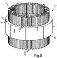
Fig. 3 in einer Draufsicht, - Fig. 5
- eine schematische Darstellung einer perspektivischen Ansicht des Stators von
Fig. 1 zu Beginn seiner Herstellung, wobei ein Perspektive bezüglichFig. 1 gedreht ist, - Fig. 6
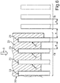
- eine schematische Darstellung eines Normalschrägungswerkzeugs beim Zusammenführen mit Leiterenden von elektrischen Leiterelementen des Stators,
- Fig. 7
- eine schematische Darstellung des Normalschrägungswerkzeugs von
Fig. 6 während einer Bewegung in Umfangsrichtung, - Fig. 8
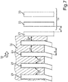
- eine schematische Darstellung eines Selektivschrägungswerkzeugs beim Zusammenführen mit den Leiterenden,
- Fig. 9
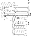
- eine schematische Darstellung des Normalschrägungswerkzeugs und des Selektivschrägungswerkzeugs zu Beginn eines Twistprozesses,
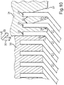
- Fig. 10
- eine schematische Darstellung des Normalschrägungswerkzeugs und des Selektivschrägungswerkzeugs während des Twistprozesses, und
- Fig. 11
- eine schematische Darstellung einer Ausführungsform der erfindungsgemäßen Werkzeuganordnung mit dem Normalschrägungswerkzeug und dem Selektivschrägungswerkzeugs für zwei Schichten einer Zweischichtwicklung.
- 1
- a schematic representation of a perspective view of an embodiment of the stator according to the invention,
- 2
- a schematic representation of a single electrical coil of the stator of
1 , - 3
- a schematic representation of a perspective view of an interconnection area of turns of the coil of FIG
2 as well as electrical connections of the coil, - 4
- a schematic representation of the interconnection area of FIG
3 in a top view, - figure 5
- a schematic representation of a perspective view of the stator of
1 at the beginning of its manufacture, taking a perspective regarding1 is rotated - 6
- a schematic representation of a normal bevel tool when it is brought together with conductor ends of electrical conductor elements of the stator,
- 7
- a schematic representation of the normal draft tool of FIG
6 during a movement in the circumferential direction, - 8
- a schematic representation of a selective bevel tool when brought together with the conductor ends,
- 9
- a schematic representation of the normal skew tool and the selective skew tool at the beginning of a twisting process,
- 10
- a schematic representation of the normal draft tool and the selective draft tool during the twisting process, and
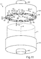
- 11
- a schematic representation of an embodiment of the tool arrangement according to the invention with the normal skew tool and the selective skew tool for two layers of a two-layer winding.
Bei dem im Folgenden erläuterten Ausführungsbeispiel handelt es sich um eine bevorzugte Ausführungsform der Erfindung.The exemplary embodiment explained below is a preferred embodiment of the invention.
In den Figuren sind funktionsgleiche Elemente jeweils mit denselben Bezugszeichen versehen.Elements with the same function are each provided with the same reference symbols in the figures.
In Nuten 4 des Blechpakets 3 sind jeweils durch eine axiale Nutöffnung 5 zwei Leiterelemente 6, 7 eingesteckt worden. Der Übersichtlichkeit halber sind von den genannten Elementen jeweils nur einige mit einem Bezugszeichen versehen. Die Leiterelemente 6, 7 jeder Nut 4 sind in einer radialen Richtung 8 fluchtend hintereinander angeordnet. Die radiale Richtung 8 ist jeweils von einer Achse 9, durch welche die axiale Richtung 3 festgelegt ist, senkrecht nach außen gerichtet. Die Achse 9 entspricht der bestimmungsgemäßen Rotationsachse eines Rotors, der in dem Stator angeordnet werden kann.Two
Durch die unterschiedlichen radialen Abstände der Leiterelemente 6, 7 entstehen zwei Ringe oder Schichten 10, 11, wobei die radial außenliegenden Leiterelemente 6 die Schicht 10 und die radial innenliegenden Leiterelemente 7 die Schicht 11 darstellen. Die Schichten 10, 11 sind Bestandteil einer Zweischichtwicklung 12 des Stators 1. Die Zweischichtwicklung 12 umfasst in dem gezeigten Beispiel sechs elektrische Spulen, von denen sich jede durch Verschalten einer jeweiligen Teilmenge der Leiterelemente 6, 7 ergibt. Jeweils ein Leiterelement der äußeren Schicht 10 und ein Leiterelement der inneren Schicht 11 bildet einen Phasenanschluss oder Spulenanschluss 13 einer der Spulen. Die Spulenanschlüsse 13 einer Spule sind jeweils in einem Verschaltungsbereich 14 angeordnet.The different radial distances between the
Zum Bilden der Windungen 16 der Spule 15 sind die Leiterelemente 6 der äußeren Schicht 11 entlang einer Umfangsrichtung U1 geschrägt oder geknickt worden, während die Leiterelemente 7 der inneren Schicht 11 in eine entgegengesetzte Umfangsrichtung U2 geknickt worden sind. Hierdurch sind die Leiterelemente 6, 7 der beiden Schichten 10, 11 miteinander verschränkt.To form the
Für das Gestalten der Spulenanschlüsse 13 und der Windungsverschaltung 17 müssen die Leiterelemente 6, 7 im Verschaltungsbereich 14 in spezieller Weise selektiv geformt sein. Die Verschaltungen der Leiterelemente 6, 7, außerhalb des Verschaltungsbereichs 14 stellen zusammen einen Normalbereich 14' dar, in welchem keine selektive Formung nötig ist.For the configuration of the
Der Verschaltungsbereich 14 ist in
In
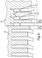
Die Leiterstücke 20 weisen des Weiteren Leiterenden 23 auf, die parallel zur Achse 9 ausgerichtet sind. Die Leiterstücke 20 weisen hierzu eine Kröpfung 24 auf.The
Die Schrägungswinkel 22 aller Schrägungsbereiche 21 der Leiterstücke 20 sind gleich. Hierdurch liegen die Leiterstücke 20 besonders dicht aufeinander. Die Leiterstücke 20 sind Bestandteil eines Wickelkopfes 25 an der Stirnseite 18 des Blechpakets 2.The helix angles 22 of all
Im Verschaltungsbereich 14 sind paarweise jeweils ein Leiterende 23 der äußeren Schicht 10 und ein Leiterende 23 der inneren Schicht 11 axial fluchtend angeordnet und elektrisch miteinander verschaltet. Die elektrische Verschaltung kann beispielsweise durch Verschweißen oder Verlöten der Leiterenden 23 erfolgt sein. Über die Leiterenden 23 im Verschaltungsbereich 14 sind die Windungen 16 miteinander verschaltet. Die Leiterenden 23 im Verschaltungsbereich 14 werden deshalb im Folgenden als Verschaltungsenden 26 bezeichnet. Die Spulenanschlüsse 13 sind jeweils durch ein Leiterende 23 gebildet, das zwischen zwei benachbarten Leiterenden 27 der jeweils anderen Schicht 10, 11 angeordnet ist.In the
Außerhalb der Verschaltungsbereiche 14 im Normalbereich 14' sind die Leiterenden 23 in gleichmäßigen Winkelabständen zueinander angeordnet. In den Verschaltungsbereichen 14 ist es dagegen notwendig, wie in
Um den Wickelkopf 25 bei dem Stator 1 auszugestalten, sind die Leiterelemente 6, 7 derart verformt worden, dass sich die Schrägungsbereiche 21 und die Kröpfung 24 ergeben und die Leiterenden 23 in den beschriebenen Relativpositionen zueinander angeordnet sind, sodass die Leiterenden 23 im Normalbereich 14' regelmäßige oder gleichmäßige Winkelabstände zueinander aufweisen und im Verschaltungsbereich 14 die Leiterenden 23 zu den Spulenanschlüssen 13 und den Verschaltungsenden 26 geformt sind.In order to design the end winding 25 in the
In
Die Stäbe 28 können entlang der axialen Richtung 3 in die Nuten 4 eingesteckt worden sein. Hierdurch ergibt sich eine Steckwicklung der elektrischen Spulen des Stators 1.The
Ausgehend von dem Stator 1 im Zustand, wie er in
Hierzu findet zunächst ein Positionierprozess statt, in welchem alle Leiterenden 6 der Schicht 10 in eine relative Endstellung zueinander gebracht werden, die sie auch bei dem fertigen Stator 1 gemäß
Nach dem Zusammenstecken der Leiterenden 23 und des Normalschrägungswerkzeugs 30 sowie des Selektivschrägungswerkzeugs 34 ist der Positionierprozess beendet, und die Leiterenden 23 aller Leiterelemente 6, 7 weisen ihre relative Endstellung auf.After the conductor ends 23 and the
In
Die Halteeinrichtung 42 kann mechanische Halteelemente aufweisen. Die Bewegungseinrichtung 43 kann zumindest einen Elektromotor und/oder eine Hydraulik aufweisen.The holding
Jeder Werkzeugbereich 44, 45 kann für jede der Spulen jeweils einen Werkzeugteil 46 aufweisen, durch welchen insgesamt für die Werkzeugbereiche 44, 45 das Selektivschrägungswerkzeug 34 gebildet ist. Weitere Werkzeugteile 47 bilden zusammen das Normalschrägungswerkzeug 30. Die Taschen der Werkzeuge 30, 34 sind in
In die Halteeinrichtung 42 kann der Stator 1 in dem in
Danach sind die Spule 15 und die übrigen Spulen im Stator 1 bereitgestellt.Thereafter, the
Für die gegenüberliegende Stirnseite 29 kann ein einfacheres Werkzeug vorgesehen sein, welches lediglich den Twistprozess ausführt, bei welchem alle Leiterenden 23 an der Stirnseite 29 um denselben Drehwinkel in die Umfangsrichtungen U1, U2 gedreht werden und hierdurch die Leiterstücke an der Stirnseite 29 miteinander gleichmäßig verschränkt werden.A simpler tool can be provided for the
Durch die Werkzeuganordnung 41 und die Prozessreihenfolge des Positionierprozesses und des Twistprozesses werden bei dem Stator 1 die aus der Stirnseite 18 herausragenden Leiterstücke 20 verschränkt. Besondere Merkmale hierbei sind das selektive Twisten zum Ausbilden der Verschaltungsbereiche 14 bei gleichzeitiger kompakter oder geringer Wickelkopfhöhe, da alle Schrägungsbereiche 21 der Leiterstücke 20 denselben Biegewinkel oder Schrägungswinkel 22 bezüglich der Stirnseite 18 aufweisen. Durch das selektive Twisten, das heißt ein unterschiedliches Behandeln der Leiterenden 23 im Normalbereich 14' und im Verschaltungsbereich 14, weisen die Leiterenden 23 bereits ihre relative Endstellung auf, bevor der Twistprozess begonnen wird. Innerhalb der Verschaltungsbereiche 14 wird durch Einführschrägen, die durch die schrägen Taschenwandungen 37 gebildet sind, auch innerhalb jedes Verschaltungsbereichs 14 bereits die relative Endstellung der Leiterenden 23 bewirkt.Due to the
Beim Positionierprozess und anschließenden Twistprozess werden die Leiterenden 23 im Verschaltungsbereich um einen Betrag weniger verschränkt als die Leiterenden 23 im Normalbereich 14'. Dies wird als negativer selektiver Twist bezeichnet. Falls die Leiterenden 23 im Verschaltungsbereich um den Betrag mehr verschränkt sind, ergibt sich dagegen ein positiver Twist. Der Verschränkungsprozess dient allgemein zur Bildung von Spulen im Statorblechpaket 2. Durch den selektiven Twist entsteht die Möglichkeit, den Wickelkopf unterschiedlich zu verschalten, indem die relative Endstellung der Leiterenden 23 im Verschaltungsbereich 14 jeweils festgelegt wird.During the positioning process and subsequent twisting process, the conductor ends 23 in the interconnection area are twisted by an amount less than the conductor ends 23 in the normal area 14'. This is called a negative selective twist. On the other hand, if the conductor ends 23 are twisted more in the wiring area by the amount, a positive twist results. The twisting process is generally used to form coils in the
Allgemein ergibt sich folgende Prozessbeschreibung. Die Leiterenden 23 der Leiterelemente 6, 7 jeder Lage oder Schicht 10, 11 werden axial in den Werkzeugbereichen 44, 45 in die dort angeordneten Taschen aufgenommen. Die Fixierung der Leiterenden 23 in den Taschen erfolgt während des Twistprozesses durch passive Klemmung. Diese wird gewährleistet durch entsprechend geringes Spiel zwischen den Leiterenden 23 und den Taschen. Die Werkzeugbereiche 44, 45 werden dann für den Twistprozess für Innen- und Außenschicht 10, 11 gegenläufig rotiert und verschränken dabei alle Leiterenden 23 gleichmäßig um einen identischen Drehwinkel entlang der Umfangsrichtung.In general, the following process description results. The conductor ends 23 of the
Durch die beschriebene Ausgestaltung der Taschen weisen die Leiterenden 23 bereits relativ zueinander fertig ausgerichtete Positionen vor dem eigentlichen Twistprozess auf. Um zu erreichen, dass die Leiterenden 23 bereits relativ zueinander fertig ausgerichtet sind, bevor durch die Werkzeuganordnung 41 der Twistprozess durchgeführt wird, müssen die Leiterenden 23 in zwei unterschiedlichen Prozessschritten in den Taschen der Werkzeugbereiche 44 beziehungsweise 45 aufgenommen werden. Der Ablauf des Umformvorganges ist dann wie folgt, wobei Bewegungen, die aufgrund von Verspannung und Rückfederung notwendig sind, hier nicht beschrieben worden sind.Due to the configuration of the pockets described, the conductor ends 23 already have positions that are completely aligned relative to one another before the actual twisting process. In order to achieve that the conductor ends 23 are already completely aligned relative to one another before the twisting process is carried out by the
Es erfolgt die Aufnahme der Leiterenden 23 für den Normalbereich 14' durch axiales Verfahren des Normalschrägungswerkzeugs 30. Dann erfolgt eine Positionierung der Leiterenden 23 des Normalbereichs 14` in Twist-Drehrichtung durch radiales Verfahren des Normalschrägungswerkzeugs 30 um den halben Drehwinkel des selektiven Twist. Anschließend erfolgt die Positionierung der Leiterenden 23 für den Verschaltungsbereich 14 um den halben Drehwinkel des selektiven Twists durch axiales Verfahren des Selektivschrägungswerkzeugs 34 mit den Einführschrägen der geschrägten Taschenwände 37. Abschließend erfolgt dann der eigentliche Twistprozess zum Ausbilden des Wickelkopfes 25.The conductor ends 23 for the normal area 14' are picked up by axially moving the
Insgesamt zeigt das Beispiel, wie durch die Erfindung eine Werkzeugvariante für das selektive Twisten beim Verschränken von Pin-Enden in der Herstellung von Motorwicklungen bereitgestellt werden kann.Overall, the example shows how the invention can provide a tool variant for selective twisting when twisting pin ends in the manufacture of motor windings.
Claims (9)
- Method for producing a stator (1), in each case one electric conductor element (6, 7) per layer (10, 11) being arranged in grooves (4) of a laminated core (2) for a radially outer layer (10) and a radially inner layer (11) of a double-layer winding (12), the conductor elements (6, 7) being provided as straight rods (28) or as U-shaped wires which, for the respective arrangement in one of the grooves (4), are plugged into an axial end of the groove (4) and are pushed in the axial direction (3) into the groove (4), and, for the configuration of coil connectors (13) of coils and a winding interconnection (17) of the coils, the conductor elements (6, 7) being in each case shaped selectively in an interconnection region (14), and the interconnections of the conductor elements (6, 7) outside the interconnection region (14) together constituting a normal region (14'), in which selective shaping is not necessary, and the conductor ends (23) of all the conductor elements (6, 7) of the layer (10, 11) then being moved relative to one another on an end side (18) of the laminated core (2) in the case of one of or the two layers (10, 11) in each case in a positioning process in the normal region (14') by way of axial plugging together of a normal bevel tool (30) with axial conductor ends (23) of the conductor elements (6, 7) of the normal region (14') and subsequent relative rotation (33) of the normal bevel tool (30) with regard to the laminated core (2), and in the interconnection region (14) by way of axial plugging together of a selective bevel tool (34) with axial conductor ends (23) of the conductor elements (6, 7) of the interconnection region (14), in such a way that the said conductor ends (23) have a relative end position with respect to one another, which relative end position is provided for the interconnection of part of the conductor ends (23) with corresponding conductor ends (23) of the other layer (11, 10), characterized in that the conductor ends (23) are to be arranged at uniform angular spacings from one another outside the interconnection regions (14) of the coils in the normal region (14'), and the angular spacings of the conductor ends (23) are to be varied in every interconnection region (14), in order to form firstly the coil connectors (13) and secondly interconnection ends (26), by way of which windings (16) of the coils are interconnected with one another, and, to this end, the normal bevel tool (30) has pockets (31) for plugging in a conductor end (23) of a conductor element (6, 7), and the selective bevel tool (34) has a plurality of pockets (35, 36) for respectively receiving the respective conductor end (23) of one of the conductor elements (6, 7) of the interconnection region (14), a pocket wall (37), arranged obliquely with regard to a plugging direction (3), of one or some of the pockets (36) moving the conductor end (23), moved into the respective pocket (36) during the plugging-together operation, along a circumferential direction (U1, U2) during the plugging-together operation of the selective bevel tool (34) with the conductor ends (23) of the conductor elements (6, 7) of the interconnection region (14), with the result that the conductor ends (23) of the conductor elements (6, 7) of the interconnection region (14) are moved relative to one another.
- Method according to Claim 1, the conductor ends (23) of the normal region (14') being moved in the circumferential direction (U1, U2) by a predetermined first rotary angle in the positioning process, and the conductor ends (23) of the interconnection region (14) being moved in the circumferential direction (U1, U2) by a respective rotary angle which is smaller in each case than the first rotary angle.
- Method according to either of the preceding claims, each conductor element (6, 7) of the layer (10, 11) protruding axially out of the end side (18) as a straight conductor piece (20) after the arranging of the conductor elements (6, 7) in the grooves (4), and then, after the positioning process, all the straight conductor pieces (20) being jointly bent in a twisting process by way of relative rotating (40) and axial bringing together (39) of the tools (30, 34) firstly and of the laminated core (2) secondly, with the result that a respective bevel region (21), formed as a result, of all the conductor pieces (20) has the same bevel angle (22) with regard to the end side (18).
- Method according to Claim 3, the conductor pieces (20) of the outer layer (10) being bent in one circumferential direction (U1), and the conductor pieces (20) of the inner layer (11) being bent in an opposite circumferential direction (U2) in the twisting process, with the result that the conductor pieces (20) of the two layers (10, 11) are arranged in a crossed manner with respect to one another.
- Method according to Claim 3 or 4, the conductor ends (23), moved by way of the normal bevel tool (30), of one of the layers (10) being arranged as a result of the twisting process in each case in a radially aligned manner with respect to corresponding conductor ends (23) of the other layer (11).
- Method according to one of Claims 3 to 5, only part of the conductor ends (26), moved by way of the selective bevel tool (23), of one of the layers (10) being arranged in a radially aligned manner with respect to corresponding conductor ends (26) of the other layer (11) after the twisting process, and one conductor end (13) of the conductor elements (6, 7) of the interconnection region (14) being arranged between two adjacent conductor ends (27) of the other layer (11) per provided electric coil (15) of the stator (1), in each case per layer.
- Method according to one of Claims 3 to 6, the conductor ends (23) being arranged in the positioning process in each case in a pocket (31, 35, 36) of the respective tool (30, 34), and each conductor element (6, 7) being bent at right angles between the bevel region (21) and the conductor end (23) by way of the twisting process, with the result that the conductor end (23) remains oriented axially.
- Tool arrangement (41) for producing a stator (1) for an electric machine, in the case of which, for the configuration of coil connectors (13) of coils and a winding interconnection (17) of the coils, conductor elements (6, 7) are in each case shaped selectively in an interconnection region (14), and interconnections of the conductor elements (6, 7) outside the interconnection region (14) together constitute a normal region (14'), in which selective shaping is not necessary, the conductor elements (6, 7) being straight rods (28) or U-shaped wires which are plugged into an axial end of a respective groove (4) of a laminated core (2) and are pushed in the axial direction (3) into the groove (4), the tool arrangement (41) having:- a normal bevel tool (30) with respective pockets (31) for plugging in a conductor end (23) of one of the conductor elements (6, 7),- a selective bevel tool (34) with respective pockets (35, 36) for plugging in a conductor end (23) of one of the conductor elements (6, 7),- a holding device (42) for holding the laminated core (2) in such a way that an end side (18) of the laminated core (2) faces the normal bevel tool (30) and the selective bevel tool (34),- a movement device (43) which is designed, in the case of a laminated core (2) which is arranged in the holding device (42) and is fitted with conductor elements (6, 7), to arrange, in a positioning process, in each case one conductor end (23) of one of the conductor elements (6, 7) in in each case one of the pockets (31, 35, 36) and, to this end, to first of all move the normal bevel tool (30) along an axial direction (3) up to the end side (18), and then to rotate it in the circumferential direction (U1, U2) with regard to the end side (18), and then to move the selective bevel tool (34) along the axial direction (3) up to the end side (18), characterized in that the conductor ends (23) are to be arranged at uniform angular spacings from one another outside the interconnection regions (14) in the normal region (14'), and the angular spacings of the conductor ends (23) are to be varied in every interconnection region (14), in order to form firstly the coil connectors (13) and secondly interconnection ends (26), by way of which windings (16) of the coils are interconnected with one another, and, to this end, in the case of the selective bevel tool (34), some of the pockets (36) have a pocket wall (37) which is arranged obliquely with regard to the axial direction (3) and by way of which, during the plugging-together operation, in each case one sliding face is formed for the respective conductor end (34) which is moved into the pocket (36), which sliding face pushes the conductor end (23) away along the circumferential direction (U1, U2).
- Tool arrangement (41) according to Claim 8, the movement device (43) being designed, after the positioning process, to bring together the normal bevel tool (30) and the selective bevel tool (34) firstly and the laminated core (2) secondly in a twisting process and, during this, to rotate the normal bevel tool (30) and the selective bevel tool (34) together relative to the laminated core (2), with the result that the conductor elements (6, 7) are bent by the same bevel angle (22) uniformly with regard to the end side (18).
Applications Claiming Priority (2)
| Application Number | Priority Date | Filing Date | Title |
|---|---|---|---|
| DE102015217922.2A DE102015217922A1 (en) | 2015-09-18 | 2015-09-18 | Method and two-part tool assembly for manufacturing a stator for an electric machine |
| PCT/EP2016/070795 WO2017045940A1 (en) | 2015-09-18 | 2016-09-05 | Method and two-part tool arrangement for producing a stator for an electrical machine |
Publications (2)
| Publication Number | Publication Date |
|---|---|
| EP3350906A1 EP3350906A1 (en) | 2018-07-25 |
| EP3350906B1 true EP3350906B1 (en) | 2022-08-31 |
Family
ID=56853643
Family Applications (1)
| Application Number | Title | Priority Date | Filing Date |
|---|---|---|---|
| EP16760089.9A Active EP3350906B1 (en) | 2015-09-18 | 2016-09-05 | Method and two-part tool arrangement for producing a stator for an electrical machine |
Country Status (5)
| Country | Link |
|---|---|
| US (1) | US10916995B2 (en) |
| EP (1) | EP3350906B1 (en) |
| CN (1) | CN107925319B (en) |
| DE (1) | DE102015217922A1 (en) |
| WO (1) | WO2017045940A1 (en) |
Families Citing this family (19)
| Publication number | Priority date | Publication date | Assignee | Title |
|---|---|---|---|---|
| DE102017114021B4 (en) * | 2017-06-23 | 2019-10-02 | Strama-Mps Maschinenbau Gmbh & Co. Kg | Device and method for processing at least one conductor segment of a winding support of an electrical machine |
| DE102017211937A1 (en) * | 2017-07-12 | 2019-01-17 | Thyssenkrupp Ag | Receiving device for positioning copper rods and assembly plant with receiving device |
| DE102017213967A1 (en) * | 2017-08-10 | 2019-02-14 | Bayerische Motoren Werke Aktiengesellschaft | Device for processing windings |
| AT520311B1 (en) * | 2017-09-01 | 2019-03-15 | Miba Ag | Method and device for the automated production of a stator of an electrical machine |
| AT519956B1 (en) * | 2017-09-01 | 2018-12-15 | Miba Ag | Process and apparatus for stator production |
| AT520356A1 (en) * | 2017-09-01 | 2019-03-15 | Miba Ag | Method and device for the automated production of a component of a stator or rotor of an electrical machine |
| DE102018206003A1 (en) * | 2018-04-19 | 2019-10-24 | Zf Friedrichshafen Ag | Device and method for aligning a hairpin winding |
| CN113039709A (en) * | 2018-11-16 | 2021-06-25 | 株式会社东芝 | Method for manufacturing stator |
| US20220060091A1 (en) * | 2018-12-21 | 2022-02-24 | Atop S.P.A. | Device and method for widening and twisting |
| CN109746345B (en) * | 2018-12-30 | 2024-03-22 | 苏州阿福机器人有限公司 | Flat wire bending device for flat wire motor winding |
| DE102019201037A1 (en) * | 2019-01-28 | 2020-01-02 | Thyssenkrupp Ag | Positioning device for positioning copper bars |
| DE102019116235A1 (en) * | 2019-06-14 | 2020-12-17 | Grob-Werke Gmbh & Co. Kg | Pick-up and rotating unit, wire end forming device provided with it, and wire end forming process |
| DE102019131995A1 (en) * | 2019-11-26 | 2021-05-27 | Grob-Werke Gmbh & Co. Kg | Pick-up and rotating unit, wire end forming device provided with it, as well as wire end forming process |
| DE102019219481A1 (en) * | 2019-12-12 | 2021-06-17 | Robert Bosch Gmbh | Tool for separating and setting wire ends of a winding as well as a method for producing a winding |
| CN115004526A (en) * | 2020-01-22 | 2022-09-02 | 小田原机械工程株式会社 | Method for twisting coil segments, twisting fixture and twisting device |
| DE102020205351A1 (en) * | 2020-04-28 | 2021-10-28 | Vitesco Technologies Germany Gmbh | Stator for an electrical machine and electrical machine with a stator |
| KR20220162291A (en) * | 2021-06-01 | 2022-12-08 | 현대자동차주식회사 | Widing device of hair pin type stator coil |
| FR3128075A1 (en) | 2021-09-20 | 2023-04-14 | Nidec Psa Emotors | Manufacturing method and stator of a rotating electrical machine with asymmetrical winding |
| WO2023062313A1 (en) | 2021-10-12 | 2023-04-20 | Nidec Psa Emotors | Manufacturing method and stator of a rotating electrical machine with asymmetric winding |
Family Cites Families (36)
| Publication number | Priority date | Publication date | Assignee | Title |
|---|---|---|---|---|
| US3834014A (en) * | 1969-06-09 | 1974-09-10 | Photocircuits Corp | Method of making laminated wire wound/armatures |
| US3641648A (en) * | 1970-08-20 | 1972-02-15 | Bell Telephone Labor Inc | Piece part handling apparatus |
| US4160926A (en) * | 1975-06-20 | 1979-07-10 | The Epoxylite Corporation | Materials and impregnating compositions for insulating electric machines |
| JPS56148812A (en) * | 1980-04-22 | 1981-11-18 | Hitachi Ltd | Winding method and apparatus |
| US4449293A (en) * | 1982-01-08 | 1984-05-22 | Hitachi, Ltd. | Coil winding and inserting machine |
| US4491281A (en) * | 1982-09-13 | 1985-01-01 | Ikari Machine Tools Co., Ltd. | Method and apparatus for winding wires |
| DE4031276A1 (en) * | 1990-10-04 | 1992-04-09 | Bosch Gmbh Robert | STAND FOR ELECTRICAL MACHINES AND METHOD FOR THE PRODUCTION THEREOF |
| US5118153A (en) * | 1991-03-06 | 1992-06-02 | H-Square Corporation | Hand-operated reciprocating bellows for electronic component pickup |
| US5778512A (en) * | 1994-12-19 | 1998-07-14 | Nippondenso Co., Ltd. | Manufacturing method for a rotor of an electric rotary machine |
| JP3309319B2 (en) * | 1995-01-20 | 2002-07-29 | フィン,デイヴィット | Apparatus and method for manufacturing coil configuration |
| US6192574B1 (en) * | 1996-11-11 | 2001-02-27 | Metget Ab | Method of manufacturing and attaching a coil to an electric circuit using a circuit fixture |
| JP3199068B2 (en) * | 1999-03-31 | 2001-08-13 | 株式会社デンソー | Stator manufacturing equipment |
| US6944932B2 (en) * | 1999-08-27 | 2005-09-20 | Giovanni Fortuna | Method for making a self-locking knot in a stator lacing machine |
| JP3589134B2 (en) * | 2000-01-12 | 2004-11-17 | 株式会社デンソー | Stator manufacturing method and apparatus |
| JP3551378B2 (en) * | 2001-12-26 | 2004-08-04 | 株式会社デンソー | Coil of rotating electric machine and method of manufacturing the same |
| JP3783659B2 (en) * | 2002-06-25 | 2006-06-07 | 株式会社デンソー | Manufacturing method of segment sequential stator coil of rotating electrical machine |
| KR20050084781A (en) * | 2002-12-11 | 2005-08-29 | 마츠시타 덴끼 산교 가부시키가이샤 | Rotary compressor |
| JP3975947B2 (en) * | 2003-03-07 | 2007-09-12 | 株式会社デンソー | Manufacturing method of winding of rotating electric machine |
| US7343662B2 (en) * | 2003-09-18 | 2008-03-18 | Denso Corporation | Manufacturing method of stator coil composed of conductor segments |
| JP2006136082A (en) * | 2004-11-04 | 2006-05-25 | Toyota Motor Corp | Method of forming twist in coil, and twisting jig, and twister |
| KR100795020B1 (en) * | 2006-08-08 | 2008-01-15 | 삼성전기주식회사 | Motor and method of manufacturing thereof |
| US8302286B2 (en) * | 2008-09-30 | 2012-11-06 | Denso Corporation | Method for manufacturing a stator winding |
| JP5361898B2 (en) * | 2008-10-06 | 2013-12-04 | 株式会社日立製作所 | Rotating electric machine |
| JP5278541B2 (en) * | 2009-04-15 | 2013-09-04 | トヨタ自動車株式会社 | Stator manufacturing method |
| JP5428763B2 (en) * | 2009-10-30 | 2014-02-26 | アイシン・エィ・ダブリュ株式会社 | Stator manufacturing method and manufacturing apparatus |
| US8661868B2 (en) * | 2010-07-28 | 2014-03-04 | Tecnomatic S.P.A. | Apparatus for twisting electrical bar conductors, in particular for bar windings of electrical machines, with conductor's clamping system |
| JP5461709B2 (en) * | 2010-12-14 | 2014-04-02 | 三菱電機株式会社 | Rotating electric machine for vehicle and manufacturing method of stator used therefor |
| CN103314508B (en) * | 2011-01-04 | 2016-02-17 | 泰克马奇有限公司 | For winding method and the fixture of the sliver end of motor bar shaped winding |
| JP5702179B2 (en) * | 2011-02-09 | 2015-04-15 | 本田技研工業株式会社 | Coil segment manufacturing method |
| JP2012205344A (en) * | 2011-03-24 | 2012-10-22 | Toyota Motor Corp | Method for manufacturing stator |
| JP5648611B2 (en) * | 2011-09-06 | 2015-01-07 | 株式会社豊田自動織機 | Manufacturing apparatus for stator of rotating electrical machine |
| US10003232B2 (en) * | 2011-12-28 | 2018-06-19 | Toyota Jidosha Kabushiki Kaisha | Rotary electric machine and stator manufacturing method |
| JP5848156B2 (en) * | 2012-02-21 | 2016-01-27 | トヨタ自動車株式会社 | Stator manufacturing method and stator manufacturing apparatus |
| WO2013190860A1 (en) * | 2012-06-22 | 2013-12-27 | 本田技研工業株式会社 | Stator manufacturing device and stator manufacturing method |
| JP5997589B2 (en) * | 2012-11-15 | 2016-09-28 | 山洋電気株式会社 | Split core type motor and method of manufacturing armature of split core type motor |
| JP5680159B1 (en) * | 2013-08-29 | 2015-03-04 | 本田技研工業株式会社 | Manufacturing method of rotating electrical machine |
-
2015
- 2015-09-18 DE DE102015217922.2A patent/DE102015217922A1/en active Pending
-
2016
- 2016-09-05 CN CN201680046448.4A patent/CN107925319B/en active Active
- 2016-09-05 WO PCT/EP2016/070795 patent/WO2017045940A1/en unknown
- 2016-09-05 EP EP16760089.9A patent/EP3350906B1/en active Active
-
2018
- 2018-03-19 US US15/924,537 patent/US10916995B2/en active Active
Also Published As
| Publication number | Publication date |
|---|---|
| EP3350906A1 (en) | 2018-07-25 |
| DE102015217922A1 (en) | 2017-03-23 |
| WO2017045940A1 (en) | 2017-03-23 |
| US20180212496A1 (en) | 2018-07-26 |
| CN107925319A (en) | 2018-04-17 |
| CN107925319B (en) | 2020-01-03 |
| US10916995B2 (en) | 2021-02-09 |
Similar Documents
| Publication | Publication Date | Title |
|---|---|---|
| EP3350906B1 (en) | Method and two-part tool arrangement for producing a stator for an electrical machine | |
| EP3642933B1 (en) | Pre-pinning nest and method for forming a ring from a plurality of u-shaped electrically conductive hairpins in order to be able to subsequently install the ring in a machine element of an electrical machine | |
| EP1614212B1 (en) | Method for producing coils and coil circuits | |
| EP2647109B1 (en) | Method for producing a stator winding of an electric machine, in particular for producing an ac generator | |
| WO2017045946A1 (en) | Method and one-piece tool assembly for producing a stator for an electrical machine | |
| EP2436102B1 (en) | Method for producing a stator winding of an electric machine, in particular for producing an alternator | |
| EP3542446B1 (en) | Wave winding coil for a stator laminated core of an electrical machine | |
| WO2007006668A1 (en) | Method for producing a winding of an electrical machine | |
| EP3534498B1 (en) | Method and device for producing a stator with a coil with skewed air coils | |
| DE102006013712A1 (en) | Method for producing a stator of a rotating electrical machine | |
| DE112009000568T5 (en) | Method for producing a sator coil | |
| EP1494338B1 (en) | Manufacturing method for a core of an electic machine | |
| DE102010053719A1 (en) | Method for manufacturing stator winding of alternating current generator for motor car, involves providing grooves with material-deforming tool, where grooves are suitable to receive coils, and arranging coils in grooves | |
| EP3167540B1 (en) | Method for producing an electrical machine using pre-formed coils and electrical machine and production tool | |
| AT522206B1 (en) | Process for providing shaped rods from an electrical conductor wire and corresponding shaped rods | |
| EP2680414B1 (en) | Method for manufacturing a coil for the generator of a wind turbine | |
| EP3084930B1 (en) | Method for producing a multi-phase winding for a stator of an electrical machine | |
| EP3446397A1 (en) | Production method for producing a stator for a synchronous or asynchronous machine | |
| WO2022069289A1 (en) | Method for producing a skewed stator | |
| EP4239868A1 (en) | Method and device for reforming conductor ends | |
| EP4233159A1 (en) | Wire-end bending apparatus and method for bending wire ends when producing an electrical machine component provided with coils | |
| WO2022161885A1 (en) | Method and tool for producing a machine component for an electric machine, machine component and electric machine | |
| DE102019220173A1 (en) | Process for bending copper rods | |
| EP3534514A1 (en) | Coil winding for a stator of a rotating electrical machine |
Legal Events
| Date | Code | Title | Description |
|---|---|---|---|
| STAA | Information on the status of an ep patent application or granted ep patent |
Free format text: STATUS: THE INTERNATIONAL PUBLICATION HAS BEEN MADE |
|
| PUAI | Public reference made under article 153(3) epc to a published international application that has entered the european phase |
Free format text: ORIGINAL CODE: 0009012 |
|
| STAA | Information on the status of an ep patent application or granted ep patent |
Free format text: STATUS: REQUEST FOR EXAMINATION WAS MADE |
|
| 17P | Request for examination filed |
Effective date: 20180418 |
|
| AK | Designated contracting states |
Kind code of ref document: A1 Designated state(s): AL AT BE BG CH CY CZ DE DK EE ES FI FR GB GR HR HU IE IS IT LI LT LU LV MC MK MT NL NO PL PT RO RS SE SI SK SM TR |
|
| AX | Request for extension of the european patent |
Extension state: BA ME |
|
| DAV | Request for validation of the european patent (deleted) | ||
| DAX | Request for extension of the european patent (deleted) | ||
| RAP1 | Party data changed (applicant data changed or rights of an application transferred) |
Owner name: VITESCO TECHNOLOGIES GMBH |
|
| STAA | Information on the status of an ep patent application or granted ep patent |
Free format text: STATUS: EXAMINATION IS IN PROGRESS |
|
| STAA | Information on the status of an ep patent application or granted ep patent |
Free format text: STATUS: EXAMINATION IS IN PROGRESS |
|
| 17Q | First examination report despatched |
Effective date: 20201222 |
|
| STAA | Information on the status of an ep patent application or granted ep patent |
Free format text: STATUS: EXAMINATION IS IN PROGRESS |
|
| RAP3 | Party data changed (applicant data changed or rights of an application transferred) |
Owner name: VITESCO TECHNOLOGIES GMBH |
|
| GRAP | Despatch of communication of intention to grant a patent |
Free format text: ORIGINAL CODE: EPIDOSNIGR1 |
|
| STAA | Information on the status of an ep patent application or granted ep patent |
Free format text: STATUS: GRANT OF PATENT IS INTENDED |
|
| INTG | Intention to grant announced |
Effective date: 20220527 |
|
| GRAS | Grant fee paid |
Free format text: ORIGINAL CODE: EPIDOSNIGR3 |
|
| GRAA | (expected) grant |
Free format text: ORIGINAL CODE: 0009210 |
|
| STAA | Information on the status of an ep patent application or granted ep patent |
Free format text: STATUS: THE PATENT HAS BEEN GRANTED |
|
| AK | Designated contracting states |
Kind code of ref document: B1 Designated state(s): AL AT BE BG CH CY CZ DE DK EE ES FI FR GB GR HR HU IE IS IT LI LT LU LV MC MK MT NL NO PL PT RO RS SE SI SK SM TR |
|
| REG | Reference to a national code |
Ref country code: CH Ref legal event code: EP Ref country code: GB Ref legal event code: FG4D Free format text: NOT ENGLISH |
|
| REG | Reference to a national code |
Ref country code: AT Ref legal event code: REF Ref document number: 1516034 Country of ref document: AT Kind code of ref document: T Effective date: 20220915 Ref country code: DE Ref legal event code: R096 Ref document number: 502016015227 Country of ref document: DE |
|
| REG | Reference to a national code |
Ref country code: IE Ref legal event code: FG4D Free format text: LANGUAGE OF EP DOCUMENT: GERMAN |
|
| REG | Reference to a national code |
Ref country code: LT Ref legal event code: MG9D |
|
| REG | Reference to a national code |
Ref country code: NL Ref legal event code: MP Effective date: 20220831 |
|
| PG25 | Lapsed in a contracting state [announced via postgrant information from national office to epo] |
Ref country code: SE Free format text: LAPSE BECAUSE OF FAILURE TO SUBMIT A TRANSLATION OF THE DESCRIPTION OR TO PAY THE FEE WITHIN THE PRESCRIBED TIME-LIMIT Effective date: 20220831 Ref country code: RS Free format text: LAPSE BECAUSE OF FAILURE TO SUBMIT A TRANSLATION OF THE DESCRIPTION OR TO PAY THE FEE WITHIN THE PRESCRIBED TIME-LIMIT Effective date: 20220831 Ref country code: NO Free format text: LAPSE BECAUSE OF FAILURE TO SUBMIT A TRANSLATION OF THE DESCRIPTION OR TO PAY THE FEE WITHIN THE PRESCRIBED TIME-LIMIT Effective date: 20221130 Ref country code: LV Free format text: LAPSE BECAUSE OF FAILURE TO SUBMIT A TRANSLATION OF THE DESCRIPTION OR TO PAY THE FEE WITHIN THE PRESCRIBED TIME-LIMIT Effective date: 20220831 Ref country code: LT Free format text: LAPSE BECAUSE OF FAILURE TO SUBMIT A TRANSLATION OF THE DESCRIPTION OR TO PAY THE FEE WITHIN THE PRESCRIBED TIME-LIMIT Effective date: 20220831 Ref country code: FI Free format text: LAPSE BECAUSE OF FAILURE TO SUBMIT A TRANSLATION OF THE DESCRIPTION OR TO PAY THE FEE WITHIN THE PRESCRIBED TIME-LIMIT Effective date: 20220831 |
|
| PG25 | Lapsed in a contracting state [announced via postgrant information from national office to epo] |
Ref country code: PL Free format text: LAPSE BECAUSE OF FAILURE TO SUBMIT A TRANSLATION OF THE DESCRIPTION OR TO PAY THE FEE WITHIN THE PRESCRIBED TIME-LIMIT Effective date: 20220831 Ref country code: IS Free format text: LAPSE BECAUSE OF FAILURE TO SUBMIT A TRANSLATION OF THE DESCRIPTION OR TO PAY THE FEE WITHIN THE PRESCRIBED TIME-LIMIT Effective date: 20221231 Ref country code: HR Free format text: LAPSE BECAUSE OF FAILURE TO SUBMIT A TRANSLATION OF THE DESCRIPTION OR TO PAY THE FEE WITHIN THE PRESCRIBED TIME-LIMIT Effective date: 20220831 Ref country code: GR Free format text: LAPSE BECAUSE OF FAILURE TO SUBMIT A TRANSLATION OF THE DESCRIPTION OR TO PAY THE FEE WITHIN THE PRESCRIBED TIME-LIMIT Effective date: 20221201 |
|
| PG25 | Lapsed in a contracting state [announced via postgrant information from national office to epo] |
Ref country code: SM Free format text: LAPSE BECAUSE OF FAILURE TO SUBMIT A TRANSLATION OF THE DESCRIPTION OR TO PAY THE FEE WITHIN THE PRESCRIBED TIME-LIMIT Effective date: 20220831 Ref country code: RO Free format text: LAPSE BECAUSE OF FAILURE TO SUBMIT A TRANSLATION OF THE DESCRIPTION OR TO PAY THE FEE WITHIN THE PRESCRIBED TIME-LIMIT Effective date: 20220831 Ref country code: PT Free format text: LAPSE BECAUSE OF FAILURE TO SUBMIT A TRANSLATION OF THE DESCRIPTION OR TO PAY THE FEE WITHIN THE PRESCRIBED TIME-LIMIT Effective date: 20230102 Ref country code: ES Free format text: LAPSE BECAUSE OF FAILURE TO SUBMIT A TRANSLATION OF THE DESCRIPTION OR TO PAY THE FEE WITHIN THE PRESCRIBED TIME-LIMIT Effective date: 20220831 Ref country code: DK Free format text: LAPSE BECAUSE OF FAILURE TO SUBMIT A TRANSLATION OF THE DESCRIPTION OR TO PAY THE FEE WITHIN THE PRESCRIBED TIME-LIMIT Effective date: 20220831 Ref country code: CZ Free format text: LAPSE BECAUSE OF FAILURE TO SUBMIT A TRANSLATION OF THE DESCRIPTION OR TO PAY THE FEE WITHIN THE PRESCRIBED TIME-LIMIT Effective date: 20220831 |
|
| REG | Reference to a national code |
Ref country code: CH Ref legal event code: PL |
|
| REG | Reference to a national code |
Ref country code: BE Ref legal event code: MM Effective date: 20220930 |
|
| PG25 | Lapsed in a contracting state [announced via postgrant information from national office to epo] |
Ref country code: SK Free format text: LAPSE BECAUSE OF FAILURE TO SUBMIT A TRANSLATION OF THE DESCRIPTION OR TO PAY THE FEE WITHIN THE PRESCRIBED TIME-LIMIT Effective date: 20220831 Ref country code: MC Free format text: LAPSE BECAUSE OF FAILURE TO SUBMIT A TRANSLATION OF THE DESCRIPTION OR TO PAY THE FEE WITHIN THE PRESCRIBED TIME-LIMIT Effective date: 20220831 Ref country code: EE Free format text: LAPSE BECAUSE OF FAILURE TO SUBMIT A TRANSLATION OF THE DESCRIPTION OR TO PAY THE FEE WITHIN THE PRESCRIBED TIME-LIMIT Effective date: 20220831 |
|
| REG | Reference to a national code |
Ref country code: DE Ref legal event code: R097 Ref document number: 502016015227 Country of ref document: DE |
|
| PG25 | Lapsed in a contracting state [announced via postgrant information from national office to epo] |
Ref country code: NL Free format text: LAPSE BECAUSE OF FAILURE TO SUBMIT A TRANSLATION OF THE DESCRIPTION OR TO PAY THE FEE WITHIN THE PRESCRIBED TIME-LIMIT Effective date: 20220831 Ref country code: LU Free format text: LAPSE BECAUSE OF NON-PAYMENT OF DUE FEES Effective date: 20220905 Ref country code: AL Free format text: LAPSE BECAUSE OF FAILURE TO SUBMIT A TRANSLATION OF THE DESCRIPTION OR TO PAY THE FEE WITHIN THE PRESCRIBED TIME-LIMIT Effective date: 20220831 |
|
| PLBE | No opposition filed within time limit |
Free format text: ORIGINAL CODE: 0009261 |
|
| STAA | Information on the status of an ep patent application or granted ep patent |
Free format text: STATUS: NO OPPOSITION FILED WITHIN TIME LIMIT |
|
| P01 | Opt-out of the competence of the unified patent court (upc) registered |
Effective date: 20230530 |
|
| GBPC | Gb: european patent ceased through non-payment of renewal fee |
Effective date: 20221130 |
|
| PG25 | Lapsed in a contracting state [announced via postgrant information from national office to epo] |
Ref country code: LI Free format text: LAPSE BECAUSE OF NON-PAYMENT OF DUE FEES Effective date: 20220930 Ref country code: IE Free format text: LAPSE BECAUSE OF NON-PAYMENT OF DUE FEES Effective date: 20220905 Ref country code: FR Free format text: LAPSE BECAUSE OF NON-PAYMENT OF DUE FEES Effective date: 20221031 Ref country code: CH Free format text: LAPSE BECAUSE OF NON-PAYMENT OF DUE FEES Effective date: 20220930 |
|
| 26N | No opposition filed |
Effective date: 20230601 |
|
| PG25 | Lapsed in a contracting state [announced via postgrant information from national office to epo] |
Ref country code: SI Free format text: LAPSE BECAUSE OF FAILURE TO SUBMIT A TRANSLATION OF THE DESCRIPTION OR TO PAY THE FEE WITHIN THE PRESCRIBED TIME-LIMIT Effective date: 20220831 |
|
| PG25 | Lapsed in a contracting state [announced via postgrant information from national office to epo] |
Ref country code: BE Free format text: LAPSE BECAUSE OF NON-PAYMENT OF DUE FEES Effective date: 20220930 |
|
| PG25 | Lapsed in a contracting state [announced via postgrant information from national office to epo] |
Ref country code: GB Free format text: LAPSE BECAUSE OF NON-PAYMENT OF DUE FEES Effective date: 20221130 |
|
| REG | Reference to a national code |
Ref country code: AT Ref legal event code: MM01 Ref document number: 1516034 Country of ref document: AT Kind code of ref document: T Effective date: 20220905 |
|
| PGFP | Annual fee paid to national office [announced via postgrant information from national office to epo] |
Ref country code: DE Payment date: 20230930 Year of fee payment: 8 |
|
| PG25 | Lapsed in a contracting state [announced via postgrant information from national office to epo] |
Ref country code: AT Free format text: LAPSE BECAUSE OF NON-PAYMENT OF DUE FEES Effective date: 20220905 |
|
| PG25 | Lapsed in a contracting state [announced via postgrant information from national office to epo] |
Ref country code: HU Free format text: LAPSE BECAUSE OF FAILURE TO SUBMIT A TRANSLATION OF THE DESCRIPTION OR TO PAY THE FEE WITHIN THE PRESCRIBED TIME-LIMIT; INVALID AB INITIO Effective date: 20160905 |