EP3350552B1 - Methode de mesure du niveau de remplissage d'un materiau dans un conteneur - Google Patents
Methode de mesure du niveau de remplissage d'un materiau dans un conteneur Download PDFInfo
- Publication number
- EP3350552B1 EP3350552B1 EP16731583.7A EP16731583A EP3350552B1 EP 3350552 B1 EP3350552 B1 EP 3350552B1 EP 16731583 A EP16731583 A EP 16731583A EP 3350552 B1 EP3350552 B1 EP 3350552B1
- Authority
- EP
- European Patent Office
- Prior art keywords
- microwave
- pulse
- microwave pulse
- time
- reflected
- Prior art date
- Legal status (The legal status is an assumption and is not a legal conclusion. Google has not performed a legal analysis and makes no representation as to the accuracy of the status listed.)
- Active
Links
Images


Classifications
-
- G—PHYSICS
- G01—MEASURING; TESTING
- G01F—MEASURING VOLUME, VOLUME FLOW, MASS FLOW OR LIQUID LEVEL; METERING BY VOLUME
- G01F23/00—Indicating or measuring liquid level or level of fluent solid material, e.g. indicating in terms of volume or indicating by means of an alarm
- G01F23/22—Indicating or measuring liquid level or level of fluent solid material, e.g. indicating in terms of volume or indicating by means of an alarm by measuring physical variables, other than linear dimensions, pressure or weight, dependent on the level to be measured, e.g. by difference of heat transfer of steam or water
- G01F23/28—Indicating or measuring liquid level or level of fluent solid material, e.g. indicating in terms of volume or indicating by means of an alarm by measuring physical variables, other than linear dimensions, pressure or weight, dependent on the level to be measured, e.g. by difference of heat transfer of steam or water by measuring the variations of parameters of electromagnetic or acoustic waves applied directly to the liquid or fluent solid material
- G01F23/284—Electromagnetic waves
-
- G—PHYSICS
- G01—MEASURING; TESTING
- G01S—RADIO DIRECTION-FINDING; RADIO NAVIGATION; DETERMINING DISTANCE OR VELOCITY BY USE OF RADIO WAVES; LOCATING OR PRESENCE-DETECTING BY USE OF THE REFLECTION OR RERADIATION OF RADIO WAVES; ANALOGOUS ARRANGEMENTS USING OTHER WAVES
- G01S13/00—Systems using the reflection or reradiation of radio waves, e.g. radar systems; Analogous systems using reflection or reradiation of waves whose nature or wavelength is irrelevant or unspecified
- G01S13/02—Systems using reflection of radio waves, e.g. primary radar systems; Analogous systems
- G01S13/06—Systems determining position data of a target
- G01S13/08—Systems for measuring distance only
- G01S13/10—Systems for measuring distance only using transmission of interrupted, pulse modulated waves
- G01S13/12—Systems for measuring distance only using transmission of interrupted, pulse modulated waves wherein the pulse-recurrence frequency is varied to provide a desired time relationship between the transmission of a pulse and the receipt of the echo of a preceding pulse
-
- G—PHYSICS
- G01—MEASURING; TESTING
- G01S—RADIO DIRECTION-FINDING; RADIO NAVIGATION; DETERMINING DISTANCE OR VELOCITY BY USE OF RADIO WAVES; LOCATING OR PRESENCE-DETECTING BY USE OF THE REFLECTION OR RERADIATION OF RADIO WAVES; ANALOGOUS ARRANGEMENTS USING OTHER WAVES
- G01S13/00—Systems using the reflection or reradiation of radio waves, e.g. radar systems; Analogous systems using reflection or reradiation of waves whose nature or wavelength is irrelevant or unspecified
- G01S13/88—Radar or analogous systems specially adapted for specific applications
-
- G—PHYSICS
- G01—MEASURING; TESTING
- G01S—RADIO DIRECTION-FINDING; RADIO NAVIGATION; DETERMINING DISTANCE OR VELOCITY BY USE OF RADIO WAVES; LOCATING OR PRESENCE-DETECTING BY USE OF THE REFLECTION OR RERADIATION OF RADIO WAVES; ANALOGOUS ARRANGEMENTS USING OTHER WAVES
- G01S7/00—Details of systems according to groups G01S13/00, G01S15/00, G01S17/00
- G01S7/02—Details of systems according to groups G01S13/00, G01S15/00, G01S17/00 of systems according to group G01S13/00
- G01S7/28—Details of pulse systems
- G01S7/285—Receivers
- G01S7/292—Extracting wanted echo-signals
Definitions
- the invention relates to a method for measuring the level of a filling material located in a container by means of microwave pulses, as well as a suitable for carrying out this method level gauge.
- field devices are often used which serve to detect and / or influence process variables.
- Sensors that are used, for example, in level gauges, flowmeters, pressure and temperature measuring devices, pH redox potential measuring devices, conductivity meters, etc., which contain the corresponding process variables level, flow, pressure, temperature, pH, Detect redox potential or conductivity.
- actuators such as valves or pumps, via which the flow of a liquid in a pipe section or the level in a container can be changed.
- Field devices are in principle all those devices that are used close to the process and that provide or process process-relevant information. In the context of the invention, field devices are thus also understood as remote I / Os, radio adapters or generally electronic components which are arranged on the field level. A variety of such field devices is manufactured and sold by the company Endress + Hauser.
- non-contact measuring methods have become established, as they are robust and require little maintenance.
- Another advantage is the ability to measure steplessly.
- radar-based measuring methods which work according to the pulse transit time principle, have prevailed here.
- this measurement method also known as pulse radar, short microwave pulses are periodically sampled at a predefined repetition rate, e.g. in the order of 1 to 2 MHz and natural frequencies in the gigahertz range in the direction of the contents sent. Their reflected back in the direction of the transmitting and receiving device signal components are then received after a dependent of the distance covered in the container travel time.
- a time extension of the reflected signal can alternatively be carried out by performing a sampling of the received signal.
- a time extension of the received signal by a factor of up to 10 5 can be effected. This dramatically reduces the requirement on the meter.
- Such a method for time expansion is now the standard method in the field of pulse radar-based level measurement.
- a corresponding method is for example in the document EP 1 324 067 A2 described.
- the resulting signal is usually subsequently rectified and fed via a low-pass filter and an analog-to-digital converter to an evaluation unit.
- the duration of the microwave pulses is determined on the basis of the resulting signal.
- a disadvantage of this method is its complicated circuitry implementation, in which especially the time expansion and the evaluation of the envelope are comparatively extensive.
- the invention is therefore based on the object to provide a radar-based method for level measurement, which can be realized with reduced circuit complexity.
- the fill level in the method according to the invention is not determined on the basis of the measured transit time, but on the basis of the self-adjusting repetition frequency with which the microwave pulses are emitted become.
- the repetition frequency is set according to the invention in that the emission of a microwave pulse is triggered by the last received microwave pulse. This results in the advantage that only the repetition frequency must be detected for level determination.
- it does not require either a highly accurate time measurement or a complex analog evaluation circuit.
- Complex digital data processing, as required by the FMCW-based method for level measurement, can also be dispensed with.
- the repetition frequency is directly proportional to the reciprocal of the transit time.
- the emission of a microwave pulse is triggered without delay after receiving the last reflected on the surface of the medium level microwave pulse. If the signal propagation time within the level gauge is neglected, the distance in this embodiment is determined directly from the reciprocal of the determined frequency multiplied by the propagation speed.
- the repetition frequency is proportional to the reciprocal of the sum of the transit time and a predefined time delay. This makes it possible to hide the near range of the level gauge. As a result, originating from there sturgeon echoes can be hidden. The depth of the hidden short range depends on the length of the time delay.
- an initiating microwave pulse is emitted in the direction of the filling material to start the measurement or in the event that no reflected on the surface of the filling material microwave pulse is received within a predetermined maximum time interval. This prevents that in these cases, the measurement is stopped, so that even without a received microwave pulse, the triggering of another microwave pulse is caused.
- the received microwave pulse is the microwave pulse reflected on the surface of the filling material, by determining the signal strength of the received microwave pulse.
- the received microwave pulse is filtered out if the signal strength is outside a predefined range. This predefined range can be determined for example by one or more calibration measurements in which the signal strength z. B. when completely empty or completely full container is measured.
- the microwave pulse to be transmitted and / or the reflected microwave pulse are amplified in this way in that the gain is increased as the repetition frequency decreases, and that the gain is reduced as the repetition frequency increases.
- This type of control also contributes to a reduced power consumption of the level gauge. This is relevant in that very high demands are placed on the explosion safety, especially in field devices in process automation, whereby the maximum allowable power consumption is severely limited.
- This advantageous type of reinforcement can thus contribute significantly, for example, to ensuring that the level gauge complies with the explosion protection regulations according to the relevant standard family EN 60079-0: 2009.
- the level measuring device further comprises a modulation unit that delays the triggering of the pulse generation unit by a delay time.
- the modulation unit By means of the modulation unit, it is possible to hide the near range, with the depth of the near range depending on the length of the time delay.
- the time delay may be a predefined impressed time delay.
- the modulation unit can also be based on hiding certain temporal segments in the form of the received signal within the transmission cycle in the form of a delay time.
- a predefined time delay can be realized in an analogous manner by logarithmically connecting line sections or by digital conversion.
- the modulation unit may be realized by means of a flip-flop based circuit or a pulse gate based circuit. This allows a temporary attenuation or complete suppression of the receive signal received by the antenna unit 4.
- the level measuring device in a further embodiment comprises an initial trigger. This serves to emit an initiating microwave pulse in the direction of the filling material for starting the measurement or in the event that no reflected on the surface of the filling material microwave pulse is received within a predetermined maximum time interval.
- At least one filter unit is provided, which checks according to one of the methods described above, whether the received microwave pulse is the microwave pulse reflected on the surface of the filling material.
- the filling level measuring device comprises at least one amplifier for amplifying the transmitted microwave pulses and / or the reflected microwave pulses.
- the amplifier amplifies the reflected microwave pulses in such a way that the amplification becomes smaller at lower frequencies Refresh rate is increased, and that the gain is reduced with increasing repetition frequency.
- overdriving of the received microwave pulses can be suppressed if they are very strongly reflected due to high fill levels. Also, this ensures a sufficient signal strength at low levels and correspondingly weakly reflected microwave pulses.
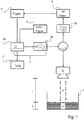
- FIG. 1 a block diagram of a level measuring device according to the invention is shown, the operation of the method according to the invention for measuring the level L of a filling material 2 located in a container 1 is illustrated.
- the level gauge is mounted in the illustration shown at a predefined height I above the bottom of the container 1. From the level gauge are cyclically emitted with a repetition frequency f pulse microwave pulses through an antenna unit 4 in the direction of the filling material 2. The microwave pulses are excited via a pulse generating unit 3 and passed through a duplexer in the antenna unit 4, where they are emitted in the direction of the filling material 2.
- the pulse generation unit 3 consists of two partial components, as is already known from the prior art in the field of pulse radar: a pulse generator 3a and a high-frequency generator 3b, which preferably has a low quality factor.
- the temporal length of the microwave pulse is regulated by the pulse generator 3a, for example a pulse shortener or a monostable flip-flop.
- the regulation takes place here taking into account the starting time, which results from the quality factor.
- the natural frequency of the microwave pulse lying in the GHz range is determined by the high frequency generator 3b, for example a Gunn or semiconductor reflex oscillator.
- the triggering of the pulse generator 3 a that is to say the time-dependent triggering of a microwave pulse, is controlled by a trigger 6.
- the microwave pulse After reflection on the surface of the medium 2, the microwave pulse is detected at a dependent on the filling level L of the filling material term t at the antenna 4 and passed through the duplexer to a filter unit 10.
- the antenna unit 4 instead of a single antenna, which operates in the transmitting and receiving direction, for separate transmission and reception also consist of two separate antennas. In this case, no duplexer is needed as a switch for the transmitted and reflected microwave pulses.
- the filter unit 10 is used to filter microwave pulses that are received by the antenna unit 4, but which are not caused by reflection on the surface of the medium 2, but for example by bluff bodies within the container 1 or by multiple echoes.
- the filtering may be based on not filtering only microwave pulses having signal strength within a predefined range. This predefined range can be determined for example by one or more calibration measurements in which the signal strength z. B. is measured at a defined level.
- the microwave pulse is detected by a detector unit 5, by which the trigger 6 is triggered.
- the repetition frequency f pulse is so depending on the Run time t that the repetition frequency increases f pulse as the running time t becomes shorter and t decreases when the running time t becomes longer.
- the filling level L which determine adjusting repetition frequency f pulse by an evaluation unit 7.
- the repetition frequency f pulse due to the direct feedback proportional to the reciprocal of the term t, if there is no relevant in-circuit propagation delay.
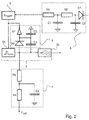
- FIG. 2 A partial detail view of the in Fig. 1 shown block diagram is in Fig. 2 shown.
- the detector unit 5 shown is composed of a rectifier diode D1 and a downstream low-pass filter, the low-pass filter consisting of two series-connected resistors R1, R2 and two capacitors C1 and C2 connected to ground.
- the initial trigger G1 is designed as a circuit of the pulse generator 3a with two capacitors C3, C4, a diode D2 and a NAND gate. In this case, the diode D2 and the capacitor also act to restart the measurement if no reflected on the surface of the filling microwave pulse was received and the cyclic transmission was interrupted accordingly.
- Evaluation unit 7 shown consists of a low-pass filter comprising a capacitor C5 connected to ground and two resistors R3, R4 located in the output path.
- the resulting DC voltage value of the output signal V out is thereby proportional to the repetition frequency f pulse , so that the output signal V out can be assigned a discrete fill level L as a result.
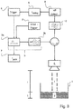
- Fig. 3 shows an advanced version of the in Fig. 1 level gauge shown.
- the extension relates to a modulation unit 8, which is arranged in the signal path between the detector unit 5 and the trigger 6.
- the modulation unit 8 By the modulation unit 8, the triggering of the trigger 6 is delayed by a delay time t delay .
- the modulation unit 8 can be constructed in an analogous manner by logarithmically connected line sections or based on digital conversion.
- the repetition frequency f pulse is proportional to the reciprocal of the sum of the transit time t and the delay time t delay .
- a temporary suppression of the received signal causes the suppression of interference echoes from the vicinity of the level gauge.
- the depth of the near range is defined by the value of the delay time t delay .
- a suitable circuitry implementation variant of the modulation unit 8 on an analog basis is disclosed in US Pat Fig. 4 shown. The circuit shown there is based on a cascade of three transistors T21, T22, T23, wherein the received signal is conducted via an input resistor R27 to the base or the gate of the input transistor T23.
- the setting of the delay time t delay is effected by an analog DC voltage V tune via a resistor R29, whereby a corresponding potential at the output of a varactor diode D21 is set.
- the capacitor C21 serves to separate this potential from the rest of the circuit.
- the delay time t delay is not configurable, but is preset by the circuit, this can be done via a corresponding dimensioning of a capacitor.
- the varactor diode D21 is replaced by a short circuit, the resistor R29 is omitted.
- transistors T21, T22, T23 are discrete bipolar transistors, since they generally have a faster response time than MOSFET transistors.
- a temporary suppression of the received signal can also be carried out on a digital basis.
- Two suitable design variants of the modulation unit 8 are shown in FIG Fig. 5a and Fig. 5b shown.
- FIG. 5a shown circuit is the blanking via a switch S11, which is switched by a flip-flop FF.
- the input signals S, R of the flip-flop are in this case formed by the received signal or the delayed with t delay received signal.
- the suppression of the received signal is achieved in that the received signal is pulled by a transistor T11 to ground.
- the control of the transistor T11 takes place via a pulse gate, whose inputs are fed by the received signal or delayed with t delay received signal.
- Fig. 5a and Fig. 5b shown variants for the digital suppression of the received signal assume that the received signal is a value discrete Has voltage level. This sets a corresponding digitization of the received signal in front of the modulation unit 8, as in Fig. 6 shown is ahead.
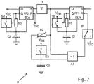
- FIGS. 7 to 9 Embodiments of the modulation unit 8 are shown, in which a digitization of the received signal is performed by an upstream gate circuit.
- the gate circuit consists of a flip-flop FF1, two switches S1, S3, an AND gate A1, a potentiometer R2 and a capacitor C2.
- the flip-flop FF1 can be triggered to the received signal or a reference pulse (in the illustrated switch position is triggered to the received signal).
- a variable dead time of the flip-flop FF1 can be effected by changing the potentiometer R2.
- the actual time delay t delay is set via the discharge curve of a resistor R1 and a capacitor C1.
- the received signal is discharged through the resistor R1 and the capacitor C1 until the level falls below a predefined threshold.
- the time delay t delay is achieved by a cascaded structure. Analogous to the first flip-flop FF1, the switch S2, the resistor R1 and the capacitor C1, a second flip-flop FF2, another RC element R3, C3 and another switch S4 are connected downstream with the same function.
- a third variant for realizing the time delay t delay is in Fig. 9 shown.
- a delay line .DELTA.t for the delay in the ns range for example suitable for this logic IC's or acoustic delay lines used.
- a signal is generated at its output Q, this signal being delayed by the delay line ⁇ t.
- a second flip-flop is triggered and a reset signal is generated for both flip-flops FF1, FF2.
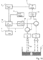
- Fig. 10 shows an expanded embodiment of the in Fig. 1 level gauge shown.
- construction includes the Antenna unit 4 two transmitting and receiving antennas, which are controlled separately via two duplexers of the pulse generating unit 3.
- the receive signals received by the two antennas are filtered in this embodiment variant in the filter unit 10 by an AND logic.
- a suppression of interference echoes can also be achieved.
- This is effected by the second additional microwave antenna emitting a second microwave pulse at the same time as the first microwave pulse in the direction of the filling material.
- the received microwave pulse is filtered out by the AND logic.
- the Fig. 11 illustrated embodiment of the level measuring device according to the invention is characterized by an additional amplifier 11, which is arranged in the receiving path between the detector unit 5 and the trigger 6 from.
- the gain A is controlled based on the repetition frequency f pulse .
- the amplifier 11 is controlled in such a way that the gain A is increased at a decreasing repetition frequency f pulse , and that the gain A is reduced at a higher repetition frequency ftrain .
- the gain is set so weak that the amplifier 11 has a signal attenuating effect.
- an equally driven amplifier can of course also be arranged in the transmission path.
- appropriately driven amplifier 11 overdriving the received microwave pulses can be suppressed if they are very strongly reflected, for example, due to high levels. This also ensures a sufficient signal strength of the received signal at low levels and correspondingly weakly reflected microwave pulses. Overall, the nature of the control also contributes to a reduced power consumption of the level gauge. This is relevant in that very high demands are placed on the explosion safety, especially in field devices in process automation, whereby the maximum allowable power consumption is severely limited.
Landscapes
- Physics & Mathematics (AREA)
- Engineering & Computer Science (AREA)
- Radar, Positioning & Navigation (AREA)
- Remote Sensing (AREA)
- General Physics & Mathematics (AREA)
- Electromagnetism (AREA)
- Computer Networks & Wireless Communication (AREA)
- Thermal Sciences (AREA)
- Fluid Mechanics (AREA)
- Radar Systems Or Details Thereof (AREA)
- Measurement Of Levels Of Liquids Or Fluent Solid Materials (AREA)
Claims (13)
- Procédé destiné à la mesure du niveau (L) d'un produit (2) se trouvant dans un réservoir, au moyen d'impulsions micro-ondes, lequel procédé comprend les étapes suivantes :- Une impulsion micro-onde est émise en direction du produit (2),- L'impulsion micro-onde est réfléchie à la surface du produit (2),- L'impulsion micro-onde réfléchie est reçue après un temps de propagation (t) dépendant du niveau (L),les étapes de procédé étant répétées de façon cyclique à une fréquence de répétition (fpuls),
caractérisé
en ce que la fréquence de répétition (fpuls) est commandée en fonction du temps de propagation (t) de telle sorte que la fréquence de répétition (fpuls) augmente à mesure que le temps de propagation (t) se raccourcit et diminue à mesure que le temps de propagation (t) s'allonge, et
procédé pour lequel le niveau (L) est déterminé au moyen de la fréquence de répétition (fpuls). - Procédé selon la revendication 1,
caractérisé
en ce que la fréquence de répétition (fpuls) est inversement proportionnelle au temps de propagation (t). - Procédé selon la revendication 1,
caractérisé
en ce que la fréquence de répétition (fpuls) est inversement proportionnelle à la somme du temps de propagation (t) et d'un temps de retard (tdelay). - Procédé selon au moins l'une des revendications précédentes,
caractérisé
en ce que, pour le démarrage de la mesure ou pour le cas où aucune impulsion micro-onde réfléchie n'est reçue à la surface du produit (2) dans un intervalle de temps maximum (Δtmax) prédéfini, une impulsion micro-onde déclenchée est émise en direction du produit (2). - Procédé selon au moins l'une des revendications précédentes,
caractérisé
en ce que l'on vérifie si, concernant l'impulsion micro-onde reçue, il s'agit d'une impulsion micro-onde réfléchie à la surface du produit (2),
en ce que- l'intensité de signal de l'impulsion micro-onde reçue est déterminée, l'impulsion micro-onde reçue étant éliminée par filtrage lorsque l'intensité du signal est en dehors d'une plage prédéfinie. - Procédé selon au moins l'une des revendications précédentes,
caractérisé
en ce que l'on vérifie si, concernant l'impulsion micro-onde reçue, il s'agit d'une impulsion micro-onde réfléchie à la surface du produit (2),
en ce que- une deuxième impulsion micro-onde est émise simultanément avec la première impulsion micro-onde en direction du produit (2),- la deuxième impulsion micro-onde est réfléchie à la surface du produit (2),- la deuxième impulsion micro-onde réfléchie est reçue après un temps de propagation (tref) dépendant du niveau (L),- le temps de propagation (tref) de la deuxième impulsion micro-onde est comparé avec le temps de propagation (t) de la première impulsion micro-onde,procédé pour lequel, dans le cas où le temps de propagation (tref) de la deuxième impulsion micro-onde ne correspond pas approximativement au temps de propagation (t) de la première impulsion micro-onde, l'impulsion micro-onde reçue est éliminée par filtrage. - Procédé selon au moins l'une des revendications précédentes,
caractérisé
en ce que l'impulsion micro-onde à émettre et/ou l'impulsion micro-onde reçue sont/est amplifiée(s) de telle sorte que l'amplification (A) diminue à mesure que la fréquence de répétition (fpuls) augmente. - Transmetteur de niveau destiné à l'exécution du procédé décrit dans au moins l'une des revendications précédentes, comprenant :- Une unité de génération d'impulsions (3) destinée à la génération d'impulsions micro-ondes,- Au moins une unité d'antenne (4) destinée à l'émission et/ou la réception d'impulsions micro-ondes,- Une unité de détection (5) destinée à la détection des impulsions micro-ondes reçues,- Un déclencheur (6) destiné au déclenchement cyclique de l'unité de génération d'impulsions (3) en fonction du temps de propagation (t), et- Une unité d'exploitation (7) destinée à la détermination de la fréquence de répétition (fpuls).
- Transmetteur de niveau selon la revendication 8, comprenant en outre- une unité de modulation (8), qui retarde le déclenchement de l'unité de génération d'impulsions (3) d'un temps de retard (tdelay).
- Transmetteur de niveau selon la revendication 8 ou 9, comprenant en outre- un déclencheur initial (9) destiné au déclenchement de l'unité de génération d'impulsions (3).
- Transmetteur de niveau selon au moins l'une des revendications 8 à 10, pour lequel est prévue au moins une unité de filtre (10), qui vérifie, d'après le procédé décrit dans la revendication 5 et/ou 6, si, concernant l'impulsion micro-onde reçue, il s'agit de l'impulsion micro-onde réfléchie à la surface du produit (2).
- Transmetteur de niveau selon au moins l'une des revendications 8 à 11,
comprenant en outre- au moins un amplificateur (11) destiné à l'amplification (A) de l'impulsion micro-onde à émettre et/ou de l'impulsion micro-onde réfléchie. - Transmetteur de niveau selon la revendication 12, pour lequel l'amplificateur (11) amplifie les impulsions micro-ondes réfléchies de telle sorte que l'amplification (A) augmente à mesure que la fréquence de répétition (fpuls) diminue et que l'amplification (A) diminue à mesure que la fréquence de répétition (fpuls) augmente.
Applications Claiming Priority (2)
| Application Number | Priority Date | Filing Date | Title |
|---|---|---|---|
| DE102015115462.5A DE102015115462A1 (de) | 2015-09-14 | 2015-09-14 | Verfahren zur Messung des Füllstands eines in einem Behälter befindlichen Füllgutes |
| PCT/EP2016/064362 WO2017045788A1 (fr) | 2015-09-14 | 2016-06-22 | Procédé de mesure du niveau d'un produit de remplissage se trouvant dans un récipient |
Publications (2)
| Publication Number | Publication Date |
|---|---|
| EP3350552A1 EP3350552A1 (fr) | 2018-07-25 |
| EP3350552B1 true EP3350552B1 (fr) | 2019-05-22 |
Family
ID=56194481
Family Applications (1)
| Application Number | Title | Priority Date | Filing Date |
|---|---|---|---|
| EP16731583.7A Active EP3350552B1 (fr) | 2015-09-14 | 2016-06-22 | Methode de mesure du niveau de remplissage d'un materiau dans un conteneur |
Country Status (5)
| Country | Link |
|---|---|
| US (1) | US20180209835A1 (fr) |
| EP (1) | EP3350552B1 (fr) |
| CN (1) | CN108139260B (fr) |
| DE (1) | DE102015115462A1 (fr) |
| WO (1) | WO2017045788A1 (fr) |
Families Citing this family (8)
| Publication number | Priority date | Publication date | Assignee | Title |
|---|---|---|---|---|
| DE102018123432A1 (de) * | 2018-09-24 | 2020-03-26 | Endress+Hauser SE+Co. KG | Detektion von Ereignis-abhängigen Zuständen bei Füllstandsmessung |
| DE102018123429A1 (de) | 2018-09-24 | 2020-03-26 | Endress+Hauser SE+Co. KG | Füllstandsmessgerät |
| DE102018127012A1 (de) * | 2018-10-30 | 2020-04-30 | Endress+Hauser SE+Co. KG | Füllstandsmessgerät |
| DE102018132870A1 (de) * | 2018-12-19 | 2020-06-25 | Endress+Hauser SE+Co. KG | Füllstandsmessgerät |
| WO2020125977A1 (fr) * | 2018-12-19 | 2020-06-25 | Rosemount Tank Radar Ab | Test d'épreuve de système de jauge de niveau radar |
| DE102019102142A1 (de) | 2019-01-29 | 2020-07-30 | Endress+Hauser SE+Co. KG | Messgerät |
| CN110879092B (zh) * | 2019-11-29 | 2020-12-01 | 安徽江淮汽车集团股份有限公司 | 一种液位监控电路 |
| DE102020114108A1 (de) | 2020-05-26 | 2021-12-02 | Endress+Hauser SE+Co. KG | Füllstandsmessgerät |
Family Cites Families (12)
| Publication number | Priority date | Publication date | Assignee | Title |
|---|---|---|---|---|
| US5233352A (en) * | 1992-05-08 | 1993-08-03 | Cournane Thomas C | Level measurement using autocorrelation |
| EP0955527B1 (fr) * | 1998-05-05 | 2007-06-27 | Endress + Hauser GmbH + Co. KG | Détecteur de niveau à micro-ondes |
| DE19949992C2 (de) * | 1999-10-15 | 2002-08-29 | Endress & Hauser Gmbh & Co Kg | Verfahren zur Erhöhung der Störfestigkeit eines Zeitbereichsreflektometers |
| DE10007187A1 (de) * | 2000-02-17 | 2001-08-23 | Endress Hauser Gmbh Co | Verfahren und Vorrichtung zur Bestimmung des Füllstandes eines Füllguts in einem Behälter |
| DE10164030A1 (de) | 2001-12-28 | 2003-07-17 | Grieshaber Vega Kg | Verfahren und Schaltungsanordnung zum Messen der Entfernung eines Gegenstandes |
| DE10360711A1 (de) * | 2003-12-19 | 2005-07-14 | Endress + Hauser Gmbh + Co. Kg | Füllstandsmeßgerät und Verfahren zur Füllstandsmessung und -überwachung |
| DE102004035757B3 (de) | 2004-07-23 | 2006-05-04 | imko Intelligente Micromodule Köhler GmbH | Anordnung zur Bestimmung der Höhe eines Flüssigkeitsstandes |
| SE0403165D0 (sv) * | 2004-12-23 | 2004-12-23 | Saab Rosemount Tank Radar Ab | A radar level gauge system |
| EP2226615B1 (fr) * | 2009-03-02 | 2018-08-22 | VEGA Grieshaber KG | Mesures de niveaux de remplissage à l'aide d'une évaluation d'une courbe d'écho |
| US9024806B2 (en) * | 2012-05-10 | 2015-05-05 | Rosemount Tank Radar Ab | Radar level gauge with MCU timing circuit |
| DE102012107146A1 (de) * | 2012-08-03 | 2014-02-20 | Endress + Hauser Gmbh + Co. Kg | Verfahren zur Bestimmung und/oder Überwachung des Füllstands eines Mediums in einem Behälter |
| DE102012109101A1 (de) * | 2012-09-26 | 2014-03-27 | Endress + Hauser Gmbh + Co. Kg | Füllstandsmessgerät |
-
2015
- 2015-09-14 DE DE102015115462.5A patent/DE102015115462A1/de not_active Withdrawn
-
2016
- 2016-06-22 EP EP16731583.7A patent/EP3350552B1/fr active Active
- 2016-06-22 WO PCT/EP2016/064362 patent/WO2017045788A1/fr not_active Ceased
- 2016-06-22 US US15/758,427 patent/US20180209835A1/en not_active Abandoned
- 2016-06-22 CN CN201680052809.6A patent/CN108139260B/zh active Active
Non-Patent Citations (1)
| Title |
|---|
| None * |
Also Published As
| Publication number | Publication date |
|---|---|
| US20180209835A1 (en) | 2018-07-26 |
| CN108139260B (zh) | 2019-12-31 |
| CN108139260A (zh) | 2018-06-08 |
| EP3350552A1 (fr) | 2018-07-25 |
| DE102015115462A1 (de) | 2017-03-16 |
| WO2017045788A1 (fr) | 2017-03-23 |
Similar Documents
| Publication | Publication Date | Title |
|---|---|---|
| EP3350552B1 (fr) | Methode de mesure du niveau de remplissage d'un materiau dans un conteneur | |
| DE69425373T2 (de) | Elektromagnetischer verdecktengegenstanddetektor | |
| EP0955527B1 (fr) | Détecteur de niveau à micro-ondes | |
| EP1324067B1 (fr) | Procédé et circuit pour la mesure de la distance d'un objet | |
| EP2942644B1 (fr) | Capteur télémétrique et procédé destiné à la détection et la détermination de l'éloignement d'objets | |
| EP3418700A1 (fr) | Appareil de radiodétection de niveau de remplissage à adaptation automatique de la fréquence | |
| EP3308110B1 (fr) | Procédé et dispositif pour contrôler la fonctionnalité d'un appareil de mesure du niveau de remplissage basé sur un radar | |
| EP1695044A2 (fr) | Appareil de mesure d'un niveau de remplissage et procede de mesure et de surveillance du niveau de remplissage | |
| WO2013092099A1 (fr) | Procédé et appareil pour mesurer le niveau de remplissage | |
| EP0535196A1 (fr) | Procede et dispositif pour la mesure de distance selon le principe de la retroreflection. | |
| DE102015107419A1 (de) | Radarvorrichtung | |
| EP2440949B1 (fr) | Procédé et dispositif pour mesurer une variation de distance | |
| DE2126917A1 (de) | Kohärenzpuls-Dopplerhöhenmesser | |
| EP3746753B1 (fr) | Procédé de détection d'états d'erreur potentiels sur un dispositif de mesure de remplissage à base de fmcw | |
| EP3258296A1 (fr) | Armoire de micro-ondes de reflexion | |
| DE102015120736B4 (de) | Verfahren und Füllstandsmessgerät zur Bestimmung des Füllstands eines in einem Behälter befindlichen Füllgutes | |
| DE102004062023B4 (de) | Radarsystem zur Überwachung von Zielen in verschiedenen Entfernungsbereichen | |
| DE102015120362A1 (de) | Verfahren zur Radar-basierten Messung des Füllstands | |
| DE102006039517A1 (de) | Verfahren zum Betreiben eines Radarsystems und Radarsystem | |
| EP1039273B1 (fr) | Procédé de mesure du niveau d' un fluide | |
| EP3009858B1 (fr) | Dispositif radar de détection des nuages | |
| DE102015109480B3 (de) | Verfahren und Vorrichtung zur Bestimmung des Füllstandes eines in einem Behälter befindlichen Füllgutes | |
| EP1449008B1 (fr) | Radar a onde continue a modulation de frequence (fmcw), avec limitation du temps d'emission pour eviter les effets de repliement de spectre | |
| EP1413896A2 (fr) | Procédé pour le fonctionnement d'un capteur radar et dispositif correspondant | |
| EP3605029B1 (fr) | Procédé de détermination d'un état de commutation d'un capteur d'impédance et capteur d'impédance |
Legal Events
| Date | Code | Title | Description |
|---|---|---|---|
| STAA | Information on the status of an ep patent application or granted ep patent |
Free format text: STATUS: THE INTERNATIONAL PUBLICATION HAS BEEN MADE |
|
| PUAI | Public reference made under article 153(3) epc to a published international application that has entered the european phase |
Free format text: ORIGINAL CODE: 0009012 |
|
| STAA | Information on the status of an ep patent application or granted ep patent |
Free format text: STATUS: REQUEST FOR EXAMINATION WAS MADE |
|
| 17P | Request for examination filed |
Effective date: 20180221 |
|
| AK | Designated contracting states |
Kind code of ref document: A1 Designated state(s): AL AT BE BG CH CY CZ DE DK EE ES FI FR GB GR HR HU IE IS IT LI LT LU LV MC MK MT NL NO PL PT RO RS SE SI SK SM TR |
|
| AX | Request for extension of the european patent |
Extension state: BA ME |
|
| DAV | Request for validation of the european patent (deleted) | ||
| DAX | Request for extension of the european patent (deleted) | ||
| GRAP | Despatch of communication of intention to grant a patent |
Free format text: ORIGINAL CODE: EPIDOSNIGR1 |
|
| STAA | Information on the status of an ep patent application or granted ep patent |
Free format text: STATUS: GRANT OF PATENT IS INTENDED |
|
| INTG | Intention to grant announced |
Effective date: 20190122 |
|
| GRAS | Grant fee paid |
Free format text: ORIGINAL CODE: EPIDOSNIGR3 |
|
| GRAA | (expected) grant |
Free format text: ORIGINAL CODE: 0009210 |
|
| STAA | Information on the status of an ep patent application or granted ep patent |
Free format text: STATUS: THE PATENT HAS BEEN GRANTED |
|
| AK | Designated contracting states |
Kind code of ref document: B1 Designated state(s): AL AT BE BG CH CY CZ DE DK EE ES FI FR GB GR HR HU IE IS IT LI LT LU LV MC MK MT NL NO PL PT RO RS SE SI SK SM TR |
|
| REG | Reference to a national code |
Ref country code: GB Ref legal event code: FG4D Free format text: NOT ENGLISH |
|
| REG | Reference to a national code |
Ref country code: CH Ref legal event code: EP |
|
| REG | Reference to a national code |
Ref country code: IE Ref legal event code: FG4D Free format text: LANGUAGE OF EP DOCUMENT: GERMAN |
|
| REG | Reference to a national code |
Ref country code: DE Ref legal event code: R096 Ref document number: 502016004804 Country of ref document: DE |
|
| REG | Reference to a national code |
Ref country code: AT Ref legal event code: REF Ref document number: 1136677 Country of ref document: AT Kind code of ref document: T Effective date: 20190615 |
|
| REG | Reference to a national code |
Ref country code: NL Ref legal event code: MP Effective date: 20190522 |
|
| REG | Reference to a national code |
Ref country code: LT Ref legal event code: MG4D |
|
| PG25 | Lapsed in a contracting state [announced via postgrant information from national office to epo] |
Ref country code: NO Free format text: LAPSE BECAUSE OF FAILURE TO SUBMIT A TRANSLATION OF THE DESCRIPTION OR TO PAY THE FEE WITHIN THE PRESCRIBED TIME-LIMIT Effective date: 20190822 Ref country code: PT Free format text: LAPSE BECAUSE OF FAILURE TO SUBMIT A TRANSLATION OF THE DESCRIPTION OR TO PAY THE FEE WITHIN THE PRESCRIBED TIME-LIMIT Effective date: 20190922 Ref country code: FI Free format text: LAPSE BECAUSE OF FAILURE TO SUBMIT A TRANSLATION OF THE DESCRIPTION OR TO PAY THE FEE WITHIN THE PRESCRIBED TIME-LIMIT Effective date: 20190522 Ref country code: AL Free format text: LAPSE BECAUSE OF FAILURE TO SUBMIT A TRANSLATION OF THE DESCRIPTION OR TO PAY THE FEE WITHIN THE PRESCRIBED TIME-LIMIT Effective date: 20190522 Ref country code: HR Free format text: LAPSE BECAUSE OF FAILURE TO SUBMIT A TRANSLATION OF THE DESCRIPTION OR TO PAY THE FEE WITHIN THE PRESCRIBED TIME-LIMIT Effective date: 20190522 Ref country code: NL Free format text: LAPSE BECAUSE OF FAILURE TO SUBMIT A TRANSLATION OF THE DESCRIPTION OR TO PAY THE FEE WITHIN THE PRESCRIBED TIME-LIMIT Effective date: 20190522 Ref country code: SE Free format text: LAPSE BECAUSE OF FAILURE TO SUBMIT A TRANSLATION OF THE DESCRIPTION OR TO PAY THE FEE WITHIN THE PRESCRIBED TIME-LIMIT Effective date: 20190522 Ref country code: ES Free format text: LAPSE BECAUSE OF FAILURE TO SUBMIT A TRANSLATION OF THE DESCRIPTION OR TO PAY THE FEE WITHIN THE PRESCRIBED TIME-LIMIT Effective date: 20190522 Ref country code: LT Free format text: LAPSE BECAUSE OF FAILURE TO SUBMIT A TRANSLATION OF THE DESCRIPTION OR TO PAY THE FEE WITHIN THE PRESCRIBED TIME-LIMIT Effective date: 20190522 |
|
| PG25 | Lapsed in a contracting state [announced via postgrant information from national office to epo] |
Ref country code: GR Free format text: LAPSE BECAUSE OF FAILURE TO SUBMIT A TRANSLATION OF THE DESCRIPTION OR TO PAY THE FEE WITHIN THE PRESCRIBED TIME-LIMIT Effective date: 20190823 Ref country code: BG Free format text: LAPSE BECAUSE OF FAILURE TO SUBMIT A TRANSLATION OF THE DESCRIPTION OR TO PAY THE FEE WITHIN THE PRESCRIBED TIME-LIMIT Effective date: 20190822 Ref country code: RS Free format text: LAPSE BECAUSE OF FAILURE TO SUBMIT A TRANSLATION OF THE DESCRIPTION OR TO PAY THE FEE WITHIN THE PRESCRIBED TIME-LIMIT Effective date: 20190522 Ref country code: LV Free format text: LAPSE BECAUSE OF FAILURE TO SUBMIT A TRANSLATION OF THE DESCRIPTION OR TO PAY THE FEE WITHIN THE PRESCRIBED TIME-LIMIT Effective date: 20190522 |
|
| PG25 | Lapsed in a contracting state [announced via postgrant information from national office to epo] |
Ref country code: CZ Free format text: LAPSE BECAUSE OF FAILURE TO SUBMIT A TRANSLATION OF THE DESCRIPTION OR TO PAY THE FEE WITHIN THE PRESCRIBED TIME-LIMIT Effective date: 20190522 Ref country code: RO Free format text: LAPSE BECAUSE OF FAILURE TO SUBMIT A TRANSLATION OF THE DESCRIPTION OR TO PAY THE FEE WITHIN THE PRESCRIBED TIME-LIMIT Effective date: 20190522 Ref country code: EE Free format text: LAPSE BECAUSE OF FAILURE TO SUBMIT A TRANSLATION OF THE DESCRIPTION OR TO PAY THE FEE WITHIN THE PRESCRIBED TIME-LIMIT Effective date: 20190522 Ref country code: DK Free format text: LAPSE BECAUSE OF FAILURE TO SUBMIT A TRANSLATION OF THE DESCRIPTION OR TO PAY THE FEE WITHIN THE PRESCRIBED TIME-LIMIT Effective date: 20190522 Ref country code: SK Free format text: LAPSE BECAUSE OF FAILURE TO SUBMIT A TRANSLATION OF THE DESCRIPTION OR TO PAY THE FEE WITHIN THE PRESCRIBED TIME-LIMIT Effective date: 20190522 |
|
| REG | Reference to a national code |
Ref country code: CH Ref legal event code: PL |
|
| REG | Reference to a national code |
Ref country code: DE Ref legal event code: R097 Ref document number: 502016004804 Country of ref document: DE |
|
| PG25 | Lapsed in a contracting state [announced via postgrant information from national office to epo] |
Ref country code: MC Free format text: LAPSE BECAUSE OF FAILURE TO SUBMIT A TRANSLATION OF THE DESCRIPTION OR TO PAY THE FEE WITHIN THE PRESCRIBED TIME-LIMIT Effective date: 20190522 Ref country code: SM Free format text: LAPSE BECAUSE OF FAILURE TO SUBMIT A TRANSLATION OF THE DESCRIPTION OR TO PAY THE FEE WITHIN THE PRESCRIBED TIME-LIMIT Effective date: 20190522 |
|
| PLBE | No opposition filed within time limit |
Free format text: ORIGINAL CODE: 0009261 |
|
| REG | Reference to a national code |
Ref country code: BE Ref legal event code: MM Effective date: 20190630 |
|
| STAA | Information on the status of an ep patent application or granted ep patent |
Free format text: STATUS: NO OPPOSITION FILED WITHIN TIME LIMIT |
|
| PG25 | Lapsed in a contracting state [announced via postgrant information from national office to epo] |
Ref country code: TR Free format text: LAPSE BECAUSE OF FAILURE TO SUBMIT A TRANSLATION OF THE DESCRIPTION OR TO PAY THE FEE WITHIN THE PRESCRIBED TIME-LIMIT Effective date: 20190522 |
|
| 26N | No opposition filed |
Effective date: 20200225 |
|
| PG25 | Lapsed in a contracting state [announced via postgrant information from national office to epo] |
Ref country code: PL Free format text: LAPSE BECAUSE OF FAILURE TO SUBMIT A TRANSLATION OF THE DESCRIPTION OR TO PAY THE FEE WITHIN THE PRESCRIBED TIME-LIMIT Effective date: 20190522 Ref country code: IE Free format text: LAPSE BECAUSE OF NON-PAYMENT OF DUE FEES Effective date: 20190622 |
|
| PG25 | Lapsed in a contracting state [announced via postgrant information from national office to epo] |
Ref country code: BE Free format text: LAPSE BECAUSE OF NON-PAYMENT OF DUE FEES Effective date: 20190630 Ref country code: LU Free format text: LAPSE BECAUSE OF NON-PAYMENT OF DUE FEES Effective date: 20190622 Ref country code: CH Free format text: LAPSE BECAUSE OF NON-PAYMENT OF DUE FEES Effective date: 20190630 Ref country code: LI Free format text: LAPSE BECAUSE OF NON-PAYMENT OF DUE FEES Effective date: 20190630 |
|
| GBPC | Gb: european patent ceased through non-payment of renewal fee |
Effective date: 20200622 |
|
| PG25 | Lapsed in a contracting state [announced via postgrant information from national office to epo] |
Ref country code: GB Free format text: LAPSE BECAUSE OF NON-PAYMENT OF DUE FEES Effective date: 20200622 |
|
| PG25 | Lapsed in a contracting state [announced via postgrant information from national office to epo] |
Ref country code: CY Free format text: LAPSE BECAUSE OF FAILURE TO SUBMIT A TRANSLATION OF THE DESCRIPTION OR TO PAY THE FEE WITHIN THE PRESCRIBED TIME-LIMIT Effective date: 20190522 |
|
| PG25 | Lapsed in a contracting state [announced via postgrant information from national office to epo] |
Ref country code: IS Free format text: LAPSE BECAUSE OF FAILURE TO SUBMIT A TRANSLATION OF THE DESCRIPTION OR TO PAY THE FEE WITHIN THE PRESCRIBED TIME-LIMIT Effective date: 20190922 |
|
| PG25 | Lapsed in a contracting state [announced via postgrant information from national office to epo] |
Ref country code: MT Free format text: LAPSE BECAUSE OF FAILURE TO SUBMIT A TRANSLATION OF THE DESCRIPTION OR TO PAY THE FEE WITHIN THE PRESCRIBED TIME-LIMIT Effective date: 20190522 Ref country code: HU Free format text: LAPSE BECAUSE OF FAILURE TO SUBMIT A TRANSLATION OF THE DESCRIPTION OR TO PAY THE FEE WITHIN THE PRESCRIBED TIME-LIMIT; INVALID AB INITIO Effective date: 20160622 |
|
| PG25 | Lapsed in a contracting state [announced via postgrant information from national office to epo] |
Ref country code: SI Free format text: LAPSE BECAUSE OF FAILURE TO SUBMIT A TRANSLATION OF THE DESCRIPTION OR TO PAY THE FEE WITHIN THE PRESCRIBED TIME-LIMIT Effective date: 20190522 |
|
| PG25 | Lapsed in a contracting state [announced via postgrant information from national office to epo] |
Ref country code: MK Free format text: LAPSE BECAUSE OF FAILURE TO SUBMIT A TRANSLATION OF THE DESCRIPTION OR TO PAY THE FEE WITHIN THE PRESCRIBED TIME-LIMIT Effective date: 20190522 |
|
| REG | Reference to a national code |
Ref country code: AT Ref legal event code: MM01 Ref document number: 1136677 Country of ref document: AT Kind code of ref document: T Effective date: 20210622 |
|
| PG25 | Lapsed in a contracting state [announced via postgrant information from national office to epo] |
Ref country code: AT Free format text: LAPSE BECAUSE OF NON-PAYMENT OF DUE FEES Effective date: 20210622 |
|
| P01 | Opt-out of the competence of the unified patent court (upc) registered |
Effective date: 20230601 |
|
| REG | Reference to a national code |
Ref country code: DE Ref legal event code: R082 Ref document number: 502016004804 Country of ref document: DE Representative=s name: DENNEMEYER & ASSOCIATES RECHTSANWALTSGESELLSCH, DE |
|
| PGFP | Annual fee paid to national office [announced via postgrant information from national office to epo] |
Ref country code: DE Payment date: 20250618 Year of fee payment: 10 |
|
| PGFP | Annual fee paid to national office [announced via postgrant information from national office to epo] |
Ref country code: FR Payment date: 20250625 Year of fee payment: 10 |
|
| PGFP | Annual fee paid to national office [announced via postgrant information from national office to epo] |
Ref country code: IT Payment date: 20250624 Year of fee payment: 10 |