EP3350552B1 - Method for measuring the fill level of a material in a container - Google Patents
Method for measuring the fill level of a material in a container Download PDFInfo
- Publication number
- EP3350552B1 EP3350552B1 EP16731583.7A EP16731583A EP3350552B1 EP 3350552 B1 EP3350552 B1 EP 3350552B1 EP 16731583 A EP16731583 A EP 16731583A EP 3350552 B1 EP3350552 B1 EP 3350552B1
- Authority
- EP
- European Patent Office
- Prior art keywords
- microwave
- pulse
- microwave pulse
- time
- reflected
- Prior art date
- Legal status (The legal status is an assumption and is not a legal conclusion. Google has not performed a legal analysis and makes no representation as to the accuracy of the status listed.)
- Active
Links
Images


Classifications
-
- G—PHYSICS
- G01—MEASURING; TESTING
- G01F—MEASURING VOLUME, VOLUME FLOW, MASS FLOW OR LIQUID LEVEL; METERING BY VOLUME
- G01F23/00—Indicating or measuring liquid level or level of fluent solid material, e.g. indicating in terms of volume or indicating by means of an alarm
- G01F23/22—Indicating or measuring liquid level or level of fluent solid material, e.g. indicating in terms of volume or indicating by means of an alarm by measuring physical variables, other than linear dimensions, pressure or weight, dependent on the level to be measured, e.g. by difference of heat transfer of steam or water
- G01F23/28—Indicating or measuring liquid level or level of fluent solid material, e.g. indicating in terms of volume or indicating by means of an alarm by measuring physical variables, other than linear dimensions, pressure or weight, dependent on the level to be measured, e.g. by difference of heat transfer of steam or water by measuring the variations of parameters of electromagnetic or acoustic waves applied directly to the liquid or fluent solid material
- G01F23/284—Electromagnetic waves
-
- G—PHYSICS
- G01—MEASURING; TESTING
- G01S—RADIO DIRECTION-FINDING; RADIO NAVIGATION; DETERMINING DISTANCE OR VELOCITY BY USE OF RADIO WAVES; LOCATING OR PRESENCE-DETECTING BY USE OF THE REFLECTION OR RERADIATION OF RADIO WAVES; ANALOGOUS ARRANGEMENTS USING OTHER WAVES
- G01S13/00—Systems using the reflection or reradiation of radio waves, e.g. radar systems; Analogous systems using reflection or reradiation of waves whose nature or wavelength is irrelevant or unspecified
- G01S13/02—Systems using reflection of radio waves, e.g. primary radar systems; Analogous systems
- G01S13/06—Systems determining position data of a target
- G01S13/08—Systems for measuring distance only
- G01S13/10—Systems for measuring distance only using transmission of interrupted, pulse modulated waves
- G01S13/12—Systems for measuring distance only using transmission of interrupted, pulse modulated waves wherein the pulse-recurrence frequency is varied to provide a desired time relationship between the transmission of a pulse and the receipt of the echo of a preceding pulse
-
- G—PHYSICS
- G01—MEASURING; TESTING
- G01S—RADIO DIRECTION-FINDING; RADIO NAVIGATION; DETERMINING DISTANCE OR VELOCITY BY USE OF RADIO WAVES; LOCATING OR PRESENCE-DETECTING BY USE OF THE REFLECTION OR RERADIATION OF RADIO WAVES; ANALOGOUS ARRANGEMENTS USING OTHER WAVES
- G01S13/00—Systems using the reflection or reradiation of radio waves, e.g. radar systems; Analogous systems using reflection or reradiation of waves whose nature or wavelength is irrelevant or unspecified
- G01S13/88—Radar or analogous systems specially adapted for specific applications
-
- G—PHYSICS
- G01—MEASURING; TESTING
- G01S—RADIO DIRECTION-FINDING; RADIO NAVIGATION; DETERMINING DISTANCE OR VELOCITY BY USE OF RADIO WAVES; LOCATING OR PRESENCE-DETECTING BY USE OF THE REFLECTION OR RERADIATION OF RADIO WAVES; ANALOGOUS ARRANGEMENTS USING OTHER WAVES
- G01S7/00—Details of systems according to groups G01S13/00, G01S15/00, G01S17/00
- G01S7/02—Details of systems according to groups G01S13/00, G01S15/00, G01S17/00 of systems according to group G01S13/00
- G01S7/28—Details of pulse systems
- G01S7/285—Receivers
- G01S7/292—Extracting wanted echo-signals
Definitions
- the invention relates to a method for measuring the level of a filling material located in a container by means of microwave pulses, as well as a suitable for carrying out this method level gauge.
- field devices are often used which serve to detect and / or influence process variables.
- Sensors that are used, for example, in level gauges, flowmeters, pressure and temperature measuring devices, pH redox potential measuring devices, conductivity meters, etc., which contain the corresponding process variables level, flow, pressure, temperature, pH, Detect redox potential or conductivity.
- actuators such as valves or pumps, via which the flow of a liquid in a pipe section or the level in a container can be changed.
- Field devices are in principle all those devices that are used close to the process and that provide or process process-relevant information. In the context of the invention, field devices are thus also understood as remote I / Os, radio adapters or generally electronic components which are arranged on the field level. A variety of such field devices is manufactured and sold by the company Endress + Hauser.
- non-contact measuring methods have become established, as they are robust and require little maintenance.
- Another advantage is the ability to measure steplessly.
- radar-based measuring methods which work according to the pulse transit time principle, have prevailed here.
- this measurement method also known as pulse radar, short microwave pulses are periodically sampled at a predefined repetition rate, e.g. in the order of 1 to 2 MHz and natural frequencies in the gigahertz range in the direction of the contents sent. Their reflected back in the direction of the transmitting and receiving device signal components are then received after a dependent of the distance covered in the container travel time.
- a time extension of the reflected signal can alternatively be carried out by performing a sampling of the received signal.
- a time extension of the received signal by a factor of up to 10 5 can be effected. This dramatically reduces the requirement on the meter.
- Such a method for time expansion is now the standard method in the field of pulse radar-based level measurement.
- a corresponding method is for example in the document EP 1 324 067 A2 described.
- the resulting signal is usually subsequently rectified and fed via a low-pass filter and an analog-to-digital converter to an evaluation unit.
- the duration of the microwave pulses is determined on the basis of the resulting signal.
- a disadvantage of this method is its complicated circuitry implementation, in which especially the time expansion and the evaluation of the envelope are comparatively extensive.
- the invention is therefore based on the object to provide a radar-based method for level measurement, which can be realized with reduced circuit complexity.
- the fill level in the method according to the invention is not determined on the basis of the measured transit time, but on the basis of the self-adjusting repetition frequency with which the microwave pulses are emitted become.
- the repetition frequency is set according to the invention in that the emission of a microwave pulse is triggered by the last received microwave pulse. This results in the advantage that only the repetition frequency must be detected for level determination.
- it does not require either a highly accurate time measurement or a complex analog evaluation circuit.
- Complex digital data processing, as required by the FMCW-based method for level measurement, can also be dispensed with.
- the repetition frequency is directly proportional to the reciprocal of the transit time.
- the emission of a microwave pulse is triggered without delay after receiving the last reflected on the surface of the medium level microwave pulse. If the signal propagation time within the level gauge is neglected, the distance in this embodiment is determined directly from the reciprocal of the determined frequency multiplied by the propagation speed.
- the repetition frequency is proportional to the reciprocal of the sum of the transit time and a predefined time delay. This makes it possible to hide the near range of the level gauge. As a result, originating from there sturgeon echoes can be hidden. The depth of the hidden short range depends on the length of the time delay.
- an initiating microwave pulse is emitted in the direction of the filling material to start the measurement or in the event that no reflected on the surface of the filling material microwave pulse is received within a predetermined maximum time interval. This prevents that in these cases, the measurement is stopped, so that even without a received microwave pulse, the triggering of another microwave pulse is caused.
- the received microwave pulse is the microwave pulse reflected on the surface of the filling material, by determining the signal strength of the received microwave pulse.
- the received microwave pulse is filtered out if the signal strength is outside a predefined range. This predefined range can be determined for example by one or more calibration measurements in which the signal strength z. B. when completely empty or completely full container is measured.
- the microwave pulse to be transmitted and / or the reflected microwave pulse are amplified in this way in that the gain is increased as the repetition frequency decreases, and that the gain is reduced as the repetition frequency increases.
- This type of control also contributes to a reduced power consumption of the level gauge. This is relevant in that very high demands are placed on the explosion safety, especially in field devices in process automation, whereby the maximum allowable power consumption is severely limited.
- This advantageous type of reinforcement can thus contribute significantly, for example, to ensuring that the level gauge complies with the explosion protection regulations according to the relevant standard family EN 60079-0: 2009.
- the level measuring device further comprises a modulation unit that delays the triggering of the pulse generation unit by a delay time.
- the modulation unit By means of the modulation unit, it is possible to hide the near range, with the depth of the near range depending on the length of the time delay.
- the time delay may be a predefined impressed time delay.
- the modulation unit can also be based on hiding certain temporal segments in the form of the received signal within the transmission cycle in the form of a delay time.
- a predefined time delay can be realized in an analogous manner by logarithmically connecting line sections or by digital conversion.
- the modulation unit may be realized by means of a flip-flop based circuit or a pulse gate based circuit. This allows a temporary attenuation or complete suppression of the receive signal received by the antenna unit 4.
- the level measuring device in a further embodiment comprises an initial trigger. This serves to emit an initiating microwave pulse in the direction of the filling material for starting the measurement or in the event that no reflected on the surface of the filling material microwave pulse is received within a predetermined maximum time interval.
- At least one filter unit is provided, which checks according to one of the methods described above, whether the received microwave pulse is the microwave pulse reflected on the surface of the filling material.
- the filling level measuring device comprises at least one amplifier for amplifying the transmitted microwave pulses and / or the reflected microwave pulses.
- the amplifier amplifies the reflected microwave pulses in such a way that the amplification becomes smaller at lower frequencies Refresh rate is increased, and that the gain is reduced with increasing repetition frequency.
- overdriving of the received microwave pulses can be suppressed if they are very strongly reflected due to high fill levels. Also, this ensures a sufficient signal strength at low levels and correspondingly weakly reflected microwave pulses.
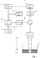
- FIG. 1 a block diagram of a level measuring device according to the invention is shown, the operation of the method according to the invention for measuring the level L of a filling material 2 located in a container 1 is illustrated.
- the level gauge is mounted in the illustration shown at a predefined height I above the bottom of the container 1. From the level gauge are cyclically emitted with a repetition frequency f pulse microwave pulses through an antenna unit 4 in the direction of the filling material 2. The microwave pulses are excited via a pulse generating unit 3 and passed through a duplexer in the antenna unit 4, where they are emitted in the direction of the filling material 2.
- the pulse generation unit 3 consists of two partial components, as is already known from the prior art in the field of pulse radar: a pulse generator 3a and a high-frequency generator 3b, which preferably has a low quality factor.
- the temporal length of the microwave pulse is regulated by the pulse generator 3a, for example a pulse shortener or a monostable flip-flop.
- the regulation takes place here taking into account the starting time, which results from the quality factor.
- the natural frequency of the microwave pulse lying in the GHz range is determined by the high frequency generator 3b, for example a Gunn or semiconductor reflex oscillator.
- the triggering of the pulse generator 3 a that is to say the time-dependent triggering of a microwave pulse, is controlled by a trigger 6.
- the microwave pulse After reflection on the surface of the medium 2, the microwave pulse is detected at a dependent on the filling level L of the filling material term t at the antenna 4 and passed through the duplexer to a filter unit 10.
- the antenna unit 4 instead of a single antenna, which operates in the transmitting and receiving direction, for separate transmission and reception also consist of two separate antennas. In this case, no duplexer is needed as a switch for the transmitted and reflected microwave pulses.
- the filter unit 10 is used to filter microwave pulses that are received by the antenna unit 4, but which are not caused by reflection on the surface of the medium 2, but for example by bluff bodies within the container 1 or by multiple echoes.
- the filtering may be based on not filtering only microwave pulses having signal strength within a predefined range. This predefined range can be determined for example by one or more calibration measurements in which the signal strength z. B. is measured at a defined level.
- the microwave pulse is detected by a detector unit 5, by which the trigger 6 is triggered.
- the repetition frequency f pulse is so depending on the Run time t that the repetition frequency increases f pulse as the running time t becomes shorter and t decreases when the running time t becomes longer.
- the filling level L which determine adjusting repetition frequency f pulse by an evaluation unit 7.
- the repetition frequency f pulse due to the direct feedback proportional to the reciprocal of the term t, if there is no relevant in-circuit propagation delay.
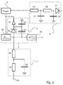
- FIG. 2 A partial detail view of the in Fig. 1 shown block diagram is in Fig. 2 shown.
- the detector unit 5 shown is composed of a rectifier diode D1 and a downstream low-pass filter, the low-pass filter consisting of two series-connected resistors R1, R2 and two capacitors C1 and C2 connected to ground.
- the initial trigger G1 is designed as a circuit of the pulse generator 3a with two capacitors C3, C4, a diode D2 and a NAND gate. In this case, the diode D2 and the capacitor also act to restart the measurement if no reflected on the surface of the filling microwave pulse was received and the cyclic transmission was interrupted accordingly.
- Evaluation unit 7 shown consists of a low-pass filter comprising a capacitor C5 connected to ground and two resistors R3, R4 located in the output path.
- the resulting DC voltage value of the output signal V out is thereby proportional to the repetition frequency f pulse , so that the output signal V out can be assigned a discrete fill level L as a result.
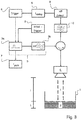
- Fig. 3 shows an advanced version of the in Fig. 1 level gauge shown.
- the extension relates to a modulation unit 8, which is arranged in the signal path between the detector unit 5 and the trigger 6.
- the modulation unit 8 By the modulation unit 8, the triggering of the trigger 6 is delayed by a delay time t delay .
- the modulation unit 8 can be constructed in an analogous manner by logarithmically connected line sections or based on digital conversion.
- the repetition frequency f pulse is proportional to the reciprocal of the sum of the transit time t and the delay time t delay .
- a temporary suppression of the received signal causes the suppression of interference echoes from the vicinity of the level gauge.
- the depth of the near range is defined by the value of the delay time t delay .
- a suitable circuitry implementation variant of the modulation unit 8 on an analog basis is disclosed in US Pat Fig. 4 shown. The circuit shown there is based on a cascade of three transistors T21, T22, T23, wherein the received signal is conducted via an input resistor R27 to the base or the gate of the input transistor T23.
- the setting of the delay time t delay is effected by an analog DC voltage V tune via a resistor R29, whereby a corresponding potential at the output of a varactor diode D21 is set.
- the capacitor C21 serves to separate this potential from the rest of the circuit.
- the delay time t delay is not configurable, but is preset by the circuit, this can be done via a corresponding dimensioning of a capacitor.
- the varactor diode D21 is replaced by a short circuit, the resistor R29 is omitted.
- transistors T21, T22, T23 are discrete bipolar transistors, since they generally have a faster response time than MOSFET transistors.
- a temporary suppression of the received signal can also be carried out on a digital basis.
- Two suitable design variants of the modulation unit 8 are shown in FIG Fig. 5a and Fig. 5b shown.
- FIG. 5a shown circuit is the blanking via a switch S11, which is switched by a flip-flop FF.
- the input signals S, R of the flip-flop are in this case formed by the received signal or the delayed with t delay received signal.
- the suppression of the received signal is achieved in that the received signal is pulled by a transistor T11 to ground.
- the control of the transistor T11 takes place via a pulse gate, whose inputs are fed by the received signal or delayed with t delay received signal.
- Fig. 5a and Fig. 5b shown variants for the digital suppression of the received signal assume that the received signal is a value discrete Has voltage level. This sets a corresponding digitization of the received signal in front of the modulation unit 8, as in Fig. 6 shown is ahead.
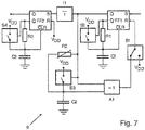
- FIGS. 7 to 9 Embodiments of the modulation unit 8 are shown, in which a digitization of the received signal is performed by an upstream gate circuit.
- the gate circuit consists of a flip-flop FF1, two switches S1, S3, an AND gate A1, a potentiometer R2 and a capacitor C2.
- the flip-flop FF1 can be triggered to the received signal or a reference pulse (in the illustrated switch position is triggered to the received signal).
- a variable dead time of the flip-flop FF1 can be effected by changing the potentiometer R2.
- the actual time delay t delay is set via the discharge curve of a resistor R1 and a capacitor C1.
- the received signal is discharged through the resistor R1 and the capacitor C1 until the level falls below a predefined threshold.
- the time delay t delay is achieved by a cascaded structure. Analogous to the first flip-flop FF1, the switch S2, the resistor R1 and the capacitor C1, a second flip-flop FF2, another RC element R3, C3 and another switch S4 are connected downstream with the same function.
- a third variant for realizing the time delay t delay is in Fig. 9 shown.
- a delay line .DELTA.t for the delay in the ns range for example suitable for this logic IC's or acoustic delay lines used.
- a signal is generated at its output Q, this signal being delayed by the delay line ⁇ t.
- a second flip-flop is triggered and a reset signal is generated for both flip-flops FF1, FF2.
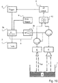
- Fig. 10 shows an expanded embodiment of the in Fig. 1 level gauge shown.
- construction includes the Antenna unit 4 two transmitting and receiving antennas, which are controlled separately via two duplexers of the pulse generating unit 3.
- the receive signals received by the two antennas are filtered in this embodiment variant in the filter unit 10 by an AND logic.
- a suppression of interference echoes can also be achieved.
- This is effected by the second additional microwave antenna emitting a second microwave pulse at the same time as the first microwave pulse in the direction of the filling material.
- the received microwave pulse is filtered out by the AND logic.
- the Fig. 11 illustrated embodiment of the level measuring device according to the invention is characterized by an additional amplifier 11, which is arranged in the receiving path between the detector unit 5 and the trigger 6 from.
- the gain A is controlled based on the repetition frequency f pulse .
- the amplifier 11 is controlled in such a way that the gain A is increased at a decreasing repetition frequency f pulse , and that the gain A is reduced at a higher repetition frequency ftrain .
- the gain is set so weak that the amplifier 11 has a signal attenuating effect.
- an equally driven amplifier can of course also be arranged in the transmission path.
- appropriately driven amplifier 11 overdriving the received microwave pulses can be suppressed if they are very strongly reflected, for example, due to high levels. This also ensures a sufficient signal strength of the received signal at low levels and correspondingly weakly reflected microwave pulses. Overall, the nature of the control also contributes to a reduced power consumption of the level gauge. This is relevant in that very high demands are placed on the explosion safety, especially in field devices in process automation, whereby the maximum allowable power consumption is severely limited.
Landscapes
- Physics & Mathematics (AREA)
- Engineering & Computer Science (AREA)
- Radar, Positioning & Navigation (AREA)
- Remote Sensing (AREA)
- General Physics & Mathematics (AREA)
- Electromagnetism (AREA)
- Computer Networks & Wireless Communication (AREA)
- Thermal Sciences (AREA)
- Fluid Mechanics (AREA)
- Radar Systems Or Details Thereof (AREA)
- Measurement Of Levels Of Liquids Or Fluent Solid Materials (AREA)
Description
Die Erfindung betrifft ein Verfahren zur Messung des Füllstands eines in einem Behälter befindlichen Füllgutes mittels Mikrowellen-Pulsen, sowie ein zur Ausführung dieses Verfahrens geeignetes Füllstandsmessgerät.The invention relates to a method for measuring the level of a filling material located in a container by means of microwave pulses, as well as a suitable for carrying out this method level gauge.
In der Automatisierungstechnik, insbesondere in der Prozessautomatisie-rungstechnik, werden vielfach Feldgeräte eingesetzt, die zur Erfassung und/oder Beeinflussung von Prozessvariablen dienen. Zur Erfassung von Prozessvariablen dienen Sensoren, die beispielsweise in Füllstandsmess-geräten, Durchflussmessgeräten, Druck- und Temperaturmessgeräten, pH-Redoxpotential-Messgeräten, Leitfähigkeitsmessgeräten, usw. integriert sind, welche die entsprechenden Prozessvariablen Füllstand, Durchfluss, Druck, Temperatur, pH-Wert, Redoxpotential bzw. Leitfähigkeit erfassen. Zur Beeinflussung von Prozessvariablen dienen Aktoren, wie zum Beispiel Ventile oder Pumpen, über die der Durchfluss einer Flüssigkeit in einem Rohrleitungsabschnitt bzw. der Füllstand in einem Behälter geändert werden kann. Als Feldgeräte werden im Prinzip alle diejenigen Geräte bezeichnet, die prozessnah eingesetzt werden und die prozessrelevante Informationen liefern oder verarbeiten. Im Zusammenhang mit der Erfindung werden unter Feldgeräten also auch Remote I/Os, Funkadapter bzw. allgemein elektronische Komponenten verstanden, die auf der Feldebene angeordnet sind. Eine Vielzahl solcher Feldgeräte wird von der Firma Endress + Hauser hergestellt und vertrieben.In automation technology, in particular in process automation technology, field devices are often used which serve to detect and / or influence process variables. Sensors that are used, for example, in level gauges, flowmeters, pressure and temperature measuring devices, pH redox potential measuring devices, conductivity meters, etc., which contain the corresponding process variables level, flow, pressure, temperature, pH, Detect redox potential or conductivity. To influence process variables are actuators, such as valves or pumps, via which the flow of a liquid in a pipe section or the level in a container can be changed. Field devices are in principle all those devices that are used close to the process and that provide or process process-relevant information. In the context of the invention, field devices are thus also understood as remote I / Os, radio adapters or generally electronic components which are arranged on the field level. A variety of such field devices is manufactured and sold by the company Endress + Hauser.
Zur Füllstandsmessung haben sich berührungslose Messverfahren etabliert, da sie robust und wartungsarm sind. Ein weiterer Vorteil besteht in der Fähigkeit, stufenlos messen zu können. Hier haben sich speziell Radar-basierte Messverfahren, die nach dem Puls-Laufzeit-Prinzip arbeiten, durchgesetzt. Bei diesem Messverfahren, welches auch unter dem Namen Pulsradar bekannt ist, werden kurze Mikrowellenpulse periodisch mit einer vordefinierten Wiederholfrequenz, z.B. in einer Größenordnung von 1 bis 2 MHz und Eigenfrequenzen im Gigahertzbereich in Richtung des Füllguts gesendet. Deren in Richtung der Sende- und Empfangseinrichtung zurück reflektierten Signalanteile werden anschließend nach einer von der im Behälter zurückgelegten Wegstrecke abhängigen Laufzeit empfangen.For level measurement, non-contact measuring methods have become established, as they are robust and require little maintenance. Another advantage is the ability to measure steplessly. Especially radar-based measuring methods, which work according to the pulse transit time principle, have prevailed here. In this measurement method, also known as pulse radar, short microwave pulses are periodically sampled at a predefined repetition rate, e.g. in the order of 1 to 2 MHz and natural frequencies in the gigahertz range in the direction of the contents sent. Their reflected back in the direction of the transmitting and receiving device signal components are then received after a dependent of the distance covered in the container travel time.
Aufgrund der hohen Ausbreitungsgeschwindigkeit der Pulse mit Lichtgeschwindigkeit ist jedoch ein sehr schneller und damit sehr komplexer Zähler in Kombination mit einer schaltungstechnisch aufwendigen Statistik erforderlich, da die Laufzeit lediglich im Bereich von Nanosekunden bis Mikrosekunden liegt. Ein nach solch einem Prinzip arbeitendes Füllstandsmessgerät ist beispielsweise in der Patentschrift
Um auf einen derart komplexen Zähler verzichten zu können, kann hilfsweise eine Zeitdehnung des reflektierten Signals durchgeführt werden, indem eine Abtastung des empfangenen Signals durchgeführt wird. Somit kann eine Zeitdehnung des empfangenen Signals um einen Faktor von bis zu 105 bewirkt werden. Hierdurch wird die Anforderung an den Zähler drastisch vermindert.In order to be able to dispense with such a complex counter, a time extension of the reflected signal can alternatively be carried out by performing a sampling of the received signal. Thus, a time extension of the received signal by a factor of up to 10 5 can be effected. This dramatically reduces the requirement on the meter.
Solch ein Verfahren zur Zeitdehnung stellt mittlerweile das Standardverfahren im Bereich der Pulsradar-basierten Füllstandsmessung dar. Ein entsprechendes Verfahren ist beispielsweise in der Druckschrift
Der Erfindung liegt daher die Aufgabe zugrunde, ein Radar-basiertes Verfahren zur Füllstandsmessung bereitzustellen, welches mit vermindertem schaltungstechnischem Aufwand realisiert werden kann.The invention is therefore based on the object to provide a radar-based method for level measurement, which can be realized with reduced circuit complexity.
Die Erfindung löst diese Aufgabe durch ein Verfahren zur Messung des Füllstands eines in einem Behälter befindlichen Füllgutes mittels Mikrowellen-Pulsen. Das Verfahren umfasst folgende Verfahrensschritte:
- Ein Mikrowellen-Puls wird in Richtung des Füllgutes ausgesendet,
- der Mikrowellen-Puls wird an der Oberfläche des Füllgutes reflektiert,
- der reflektierte Mikrowellen-Puls wird nach einer vom Füllstand abhängigen Laufzeit empfangen.
- A microwave pulse is emitted in the direction of the filling material,
- the microwave pulse is reflected at the surface of the filling material,
- the reflected microwave pulse is received after a dependent on the level of running time.
Im Gegensatz zum klassischen Pulsradar-Verfahren bestimmt sich der Füllstand beim erfindungsgemäßen Verfahren nicht anhand der gemessenen Laufzeit, sondern anhand der sich einstellenden Wiederholfrequenz, mit der die Mikrowellen-Pulse ausgesendet werden. Die Wiederholfrequenz wird erfindungsgemäß dadurch eingestellt, dass das Aussenden eines Mikrowellen-Pulses durch den zuletzt empfangenen Mikrowellen-Puls getriggert wird. Hieraus ergibt sich der Vorteil, dass zur Füllstandsbestimmung lediglich die Wiederholfrequenz erfasst werden muss. Es benötigt im Gegensatz zum klassischen Pulsradarverfahren weder eine hochgenaue Zeitmessung, noch eine aufwendige analoge Auswerteschaltung. Auch eine aufwendige digitale Datenverarbeitung, wie es beim FMCW-basierten Verfahren zur Füllstandsmessung erforderlich ist, kann entfallen.In contrast to the classical pulse radar method, the fill level in the method according to the invention is not determined on the basis of the measured transit time, but on the basis of the self-adjusting repetition frequency with which the microwave pulses are emitted become. The repetition frequency is set according to the invention in that the emission of a microwave pulse is triggered by the last received microwave pulse. This results in the advantage that only the repetition frequency must be detected for level determination. In contrast to the classical pulse radar method, it does not require either a highly accurate time measurement or a complex analog evaluation circuit. Complex digital data processing, as required by the FMCW-based method for level measurement, can also be dispensed with.
In einer ersten Ausführungsvariante ist die Wiederholfrequenz direkt proportional zu dem Kehrwert der Laufzeit. Hierdurch wird das Aussenden eines Mikrowellen-Pulses ohne Zeitverzögerung nach Empfang des zuletzt an der Oberfläche des Füllguts reflektierten Mikrowellen-Pulses getriggert. Sofern die Signallaufzeit innerhalb des Füllstandsmessgeräts vernachlässigt wird, bestimmt sich die Entfernung bei dieser Ausführungsvariante direkt aus dem Kehrwert der ermittelten Frequenz in Multiplikation mit der Ausbreitungsgeschwindigkeit.In a first embodiment variant, the repetition frequency is directly proportional to the reciprocal of the transit time. As a result, the emission of a microwave pulse is triggered without delay after receiving the last reflected on the surface of the medium level microwave pulse. If the signal propagation time within the level gauge is neglected, the distance in this embodiment is determined directly from the reciprocal of the determined frequency multiplied by the propagation speed.
Alternativ hierzu ist die Wiederholfrequenz proportional zu dem Kehrwert der Summe aus der Laufzeit und einer vordefinierten Zeitverzögerung. Dadurch ist es möglich, den Nahbereich des Füllstandsmessgeräts auszublenden. Hierdurch können von dort stammende Stör-Echos ausgeblendet werden. Die Tiefe des ausgeblendeten Nahbereichs richtet sich dabei nach der Länge der Zeitverzögerung.Alternatively, the repetition frequency is proportional to the reciprocal of the sum of the transit time and a predefined time delay. This makes it possible to hide the near range of the level gauge. As a result, originating from there sturgeon echoes can be hidden. The depth of the hidden short range depends on the length of the time delay.
In einer vorteilhaften Form des erfindungsgemäßen Verfahrens wird zum Starten der Messung oder für den Fall, dass innerhalb eines vorbestimmten maximalen Zeitintervalls kein an der Oberfläche des Füllgutes reflektierter Mikrowellen-Puls empfangen wird, ein initiierender Mikrowellen-Puls in Richtung des Füllgutes ausgesendet. Damit wird verhindert, dass in diesen Fällen die Messung gestoppt wird, so dass auch ohne empfangenen Mikrowellenpuls die Auslösung eines weiteren Mikrowellenpulses veranlasst wird.In an advantageous form of the method according to the invention, an initiating microwave pulse is emitted in the direction of the filling material to start the measurement or in the event that no reflected on the surface of the filling material microwave pulse is received within a predetermined maximum time interval. This prevents that in these cases, the measurement is stopped, so that even without a received microwave pulse, the triggering of another microwave pulse is caused.
Weiter vorteilhaft ist es, wenn zusätzlich geprüft wird, ob es sich bei dem empfangenen Mikrowellen-Puls um den an der Oberfläche des Füllgutes reflektierten Mikrowellen-Puls handelt, indem die Signalstärke des empfangenen Mikrowellen-Pulses ermittelt wird. Dabei wird der empfangene Mikrowellen-Puls herausgefiltert, wenn die Signalstärke außerhalb eines vordefinierten Bereichs liegt. Dieser vordefinierte Bereich kann beispielsweise durch eine oder mehrere Kalibrations-Messungen ermittelt werden, bei denen die Signalstärke z. B. bei komplett leerem oder komplett vollem Behälter gemessen wird.It is also advantageous if it is additionally checked whether the received microwave pulse is the microwave pulse reflected on the surface of the filling material, by determining the signal strength of the received microwave pulse. The received microwave pulse is filtered out if the signal strength is outside a predefined range. This predefined range can be determined for example by one or more calibration measurements in which the signal strength z. B. when completely empty or completely full container is measured.
Darüber hinaus kann in einer weiteren Ausgestaltungsform des Verfahrens geprüft werden, ob es sich bei dem empfangenen Mikrowellen-Puls um den an der Oberfläche des Füllgutes reflektierten Mikrowellen-Puls handelt,
indem
- ein zweiter Mikrowellen-Puls zeitgleich zum ersten Mikrowellen-Puls in Richtung des Füllgutes ausgesendet wird,
- der zweite Mikrowellen-Puls an der Oberfläche des Füllgutes reflektiert wird,
- der reflektierte zweite Mikrowellen-Puls nach einer vom Füllstand abhängigen Laufzeit empfangen wird,
- die Laufzeit des zweiten Mikrowellen-Pulses mit der Laufzeit des ersten Mikrowellen-Pulses verglichen wird.
while
- a second microwave pulse is emitted at the same time as the first microwave pulse in the direction of the filling material,
- the second microwave pulse is reflected at the surface of the filling material,
- the reflected second microwave pulse is received after a fill-dependent transit time,
- the duration of the second microwave pulse is compared with the duration of the first microwave pulse.
Um bei stark reflektierten Mikrowellen-Pulsen ein Übersteuern zu unterdrücken, und um bei schwach reflektierten Mikrowellen-Pulsen eine ausreichende Signalstärke zu gewährleisten, ist es zudem vorteilhaft, wenn der auszusendende Mikrowellen-Puls und/oder der reflektierte Mikrowellen-Puls derart verstärkt werden/wird, dass die Verstärkung bei geringer werdender Wiederholfrequenz erhöht wird, und dass die Verstärkung bei höher werdender Wiederholfrequenz verringert wird. Durch diese Art der Steuerung trägt darüber hinaus zu einem verminderten Leistungsverbrauch des Füllstandsmessgeräts bei. Dies ist insofern relevant, als dass vor allem bei Feldgeräten in der Prozessautomation sehr hohe Anforderungen an die Explosionssicherheit gestellt werden, wodurch die maximal erlaubte Leistungsaufnahme stark begrenzt ist. Diese vorteilhafte Art der Verstärkung kann also beispielsweise maßgeblich dazu beitragen, dass das Füllstandsmessgerät den Explosionsschutzbestimmungen nach der hier relevanten Normenfamilie EN 60079-0:2009 einhält.In order to suppress oversteer in the case of strongly reflected microwave pulses, and to ensure sufficient signal strength in the case of weakly reflected microwave pulses, it is also advantageous if the microwave pulse to be transmitted and / or the reflected microwave pulse are amplified in this way in that the gain is increased as the repetition frequency decreases, and that the gain is reduced as the repetition frequency increases. By this type of control also contributes to a reduced power consumption of the level gauge. This is relevant in that very high demands are placed on the explosion safety, especially in field devices in process automation, whereby the maximum allowable power consumption is severely limited. This advantageous type of reinforcement can thus contribute significantly, for example, to ensuring that the level gauge complies with the explosion protection regulations according to the relevant standard family EN 60079-0: 2009.
Die der Erfindung zugrunde liegende Aufgabe wird zudem gelöst durch ein Füllstandsmessgerät zur Ausführung des in zumindest einem der vorhergehenden Ansprüche beschriebenen Verfahrens. Hierzu umfasst das Füllstandsmessgerät:
- Eine Pulserzeugungseinheit zur zyklischen Erzeugung von Mikrowellen-Pulsen,
- zumindest eine Antennen-Einheit zum Aussenden und/oder Empfangen von Mikrowellen-Pulsen,
- eine Detektor-Einheit zur Detektion der reflektierten Mikrowellen-Pulse,
- einen Trigger zum getakteten Triggern der Pulserzeugungseinheit in Abhängigkeit der Laufzeit, und
- eine Auswerte-Einheit zur Bestimmung der Wiederholfrequenz.
- A pulse generating unit for the cyclical generation of microwave pulses,
- at least one antenna unit for transmitting and / or receiving microwave pulses,
- a detector unit for detecting the reflected microwave pulses,
- a trigger for the clocked triggering of the pulse generating unit as a function of the transit time, and
- an evaluation unit for determining the repetition frequency.
Vorteilhaft umfasst das Füllstandsmessgerät des Weiteren eine Modulations-Einheit, die die Triggerung der Pulserzeugungseinheit um eine Delay-Zeit verzögert. Mittels der Modulations-Einheit ist es möglich, den Nahbereich auszublenden, wobei sich die Tiefe des Nahbereichs nach der Länge der Zeitverzögerung richtet. Hierbei kann es sich bei der Zeitverzögerung um eine vordefiniert eingeprägte Zeitverzögerung handeln. Die Modulations-Einheit kann aber auch darauf basieren, bestimmte zeitliche Segmente in Form des Empfangssignals innerhalb des Sende-Zyklus in Form einer Delay-Zeit auszublenden. Technisch kann eine vordefinierte Zeitverzögerung auf analoge Weise durch logarithmisches Zuschalten von Leitungsstücken oder durch digitale Wandlung realisiert werden.
Alternativ kann die Modulations-Einheit mittels einer Flip-Flop basierten Schaltung oder einer Pulsgatter-basierten Schaltung realisiert sein. Dies ermöglicht eine zeitweise Dämpfung oder komplette Ausblendung des von der Antennen-Einheit 4 empfangenen Empfangssignals.Advantageously, the level measuring device further comprises a modulation unit that delays the triggering of the pulse generation unit by a delay time. By means of the modulation unit, it is possible to hide the near range, with the depth of the near range depending on the length of the time delay. Here, the time delay may be a predefined impressed time delay. However, the modulation unit can also be based on hiding certain temporal segments in the form of the received signal within the transmission cycle in the form of a delay time. Technically, a predefined time delay can be realized in an analogous manner by logarithmically connecting line sections or by digital conversion.
Alternatively, the modulation unit may be realized by means of a flip-flop based circuit or a pulse gate based circuit. This allows a temporary attenuation or complete suppression of the receive signal received by the
Zur initiierenden Triggerung der Pulserzeugungseinheit umfasst das Füllstandsmessgerät in einer weiterführenden Ausgestaltungsform einen Initial-Trigger. Dieser dient dazu, zum Starten der Messung oder für den Fall, dass innerhalb eines vorbestimmten maximalen Zeitintervalls kein an der Oberfläche des Füllgutes reflektierter Mikrowellen-Puls empfangen wird, einen initiierenden Mikrowellen-Puls in Richtung des Füllgutes auszusenden.For initiating triggering of the pulse generating unit, the level measuring device in a further embodiment comprises an initial trigger. This serves to emit an initiating microwave pulse in the direction of the filling material for starting the measurement or in the event that no reflected on the surface of the filling material microwave pulse is received within a predetermined maximum time interval.
In einer weiteren vorteilhaften Ausführungsform des Füllstandsmessgeräts ist zumindest eine Filter-Einheit vorgesehen, die nach einem der vorhergehend beschriebenen Verfahren prüft, ob es sich bei dem empfangenen Mikrowellen-Puls um den an der Oberfläche des Füllgutes reflektierten Mikrowellen-Puls handelt. Hierdurch wird gemäß dem erfindungsgemäßen Verfahren vermieden, dass aufgrund von empfangenen Mikrowellen-Pulsen, die nicht durch Reflektion an der Füllgutoberfläche hervorgerufen worden sind, ein falscher Füllstandswert ermittelt wird.In a further advantageous embodiment of the level measuring device, at least one filter unit is provided, which checks according to one of the methods described above, whether the received microwave pulse is the microwave pulse reflected on the surface of the filling material. As a result, it is avoided according to the inventive method that due to received microwave pulses, which have not been caused by reflection on the Füllgutoberfläche, a false level value is determined.
Für eine verbesserte Detektion der empfangenen Mikrowellenpulse ist es zudem von Vorteil, dass das Füllstandsmessgerät zumindest einen Verstärker zur Verstärkung der auszusendenden Mikrowellen-Pulse und/oder der reflektierten Mikrowellen-Pulse umfasst. Hierbei ist es von besonderem Vorteil, wenn der Verstärker die reflektierten Mikrowellen-Pulse derart verstärkt, dass die Verstärkung bei geringer werdender Wiederholfrequenz erhöht wird, und dass die Verstärkung bei höher werdender Wiederholfrequenz verringert wird. Hierdurch kann ein Übersteuern der empfangenen Mikrowellen-Pulse unterdrückt werden, wenn diese aufgrund von hohen Füllständen sehr stark reflektiert werden. Ebenfalls wird hierdurch bei niedrigen Füllständen und dementsprechend schwach reflektierten Mikrowellen-Pulsen eine ausreichende Signalstärke gewährleistet.For an improved detection of the received microwave pulses, it is also advantageous that the filling level measuring device comprises at least one amplifier for amplifying the transmitted microwave pulses and / or the reflected microwave pulses. In this case, it is of particular advantage if the amplifier amplifies the reflected microwave pulses in such a way that the amplification becomes smaller at lower frequencies Refresh rate is increased, and that the gain is reduced with increasing repetition frequency. As a result, overdriving of the received microwave pulses can be suppressed if they are very strongly reflected due to high fill levels. Also, this ensures a sufficient signal strength at low levels and correspondingly weakly reflected microwave pulses.
Anhand der nachfolgenden Figuren wird die Erfindung erläutert. Es zeigt:
-
Fig. 1 : Ein Blockschaltbild eines erfindungsgemäßen Füllstandsmessgeräts, -
Fig. 2 : eine ausschnittsweise Detailansicht des Blockschaltbilds, -
Fig. 3 : ein erweitertes Füllstandsmessgerät mit einer Modulations-Einheit, -
Fig. 4 : eine analoge Ausführungsform der Modulations-Einheit, -
Fig. 5a : eine digitale Ausführungsvariante der Modulations-Einheit, -
Fig. 5b : eine zweite digitale Ausführungsvariante der Modulations-Einheit, -
Fig. 6 : ein erweitertes Füllstandsmessgerät mit zwei Antennen, -
Fig. 7 : ein erweitertes Füllstandsmessgerät mit einem Verstärker, -
Fig. 8 : ein erweitertes Füllstandsmessgerät mit digitaler Verzögerungseinheit, -
Fig. 9 : eine weitere Variante einer digitalen Verzögerungseinheit, -
Fig. 10 : ein erweitertes Füllstandsmessgerät mit zwei Antennen, und -
Fig. 11 : ein erweitertes Füllstandsmessgerät mit zusätzlichem Verstärker.
-
Fig. 1 : A block diagram of a fill level measuring device according to the invention, -
Fig. 2 : a partial detail view of the block diagram, -
Fig. 3 an extended level gauge with a modulation unit, -
Fig. 4 an analogue embodiment of the modulation unit, -
Fig. 5a a digital variant of the modulation unit, -
Fig. 5b a second digital variant of the modulation unit, -
Fig. 6 : an extended level gauge with two antennas, -
Fig. 7 an extended level gauge with an amplifier, -
Fig. 8 : an extended level gauge with digital delay unit, -
Fig. 9 : another variant of a digital delay unit, -
Fig. 10 : an advanced level gauge with two antennas, and -
Fig. 11 : an advanced level gauge with additional amplifier.
Anhand von
Das Füllstandsmessgerät ist in der gezeigten Darstellung in einer vordefinierten Höhe I über dem Boden des Behälters 1 angebracht. Vom Füllstandsmessgerät werden zyklisch mit einer Wiederholfrequenz fpuls Mikrowellen-Pulse durch eine Antennen-Einheit 4 in Richtung des Füllgutes 2 ausgesendet. Die Mikrowellen-Pulse werden über eine Pulserzeugungseinheit 3 angeregt und über einen Duplexer in die Antennen-Einheit 4 geleitet, wo sie in Richtung des Füllgutes 2 abgestrahlt werden.
Die Pulserzeugungseinheit 3 besteht aus zwei Teil-Komponenten, wie es aus dem Stand der Technik im Bereich Pulsradar bereits bekannt ist: Einem Pulsgenerator 3a und einem Hochfrequenzgenerator 3b, der vorzugsweise einen geringen Gütefaktor aufweist. Hierbei wird die zeitliche Länge des Mikrowellen-Pulses durch den Pulsgenerator 3a, beispielsweise einen Pulsverkürzer oder eine monostabile Kippstufe geregelt. Die Regelung erfolgt hierbei unter Berücksichtigung der Anschwingzeit, die aus dem Gütefaktor resultiert. Die im GHz Bereich liegende Eigenfrequenz des Mikrowellen-Pulses wird durch den Hochfrequenzgenerator 3b, beispielsweise einen Gunn- oder Halbleiter-Reflex-Oszillator, festgelegt. Die Triggerung des Pulsgenerators 3a, also die zeitliche Auslösung eines Mikrowellen-Pulses, wird durch einen Trigger 6 gesteuert.
Nach Reflektion an der Oberfläche des Füllguts 2 wird des Mikrowellen-Puls nach einer von der Füllhöhe L des Füllgutes abhängigen Laufzeit t an der Antenne 4 detektiert und über den Duplexer zu einer Filter-Einheit 10 geleitet.
Alternativ zu dem in
The
After reflection on the surface of the
Alternatively to the in
Die Filter-Einheit 10 dient zur Filterung von Mikrowellen-Pulsen, die von der Antennen-Einheit 4 empfangen werden, die jedoch nicht durch Reflektion an der Oberfläche des Füllguts 2, sondern beispielsweise durch Störkörper innerhalb des Behälters 1 oder durch Mehrfachechos hervorgerufen werden. Die Filterung kann beispielsweise darauf basieren, dass nur Mikrowellen-Pulse mit einer in einem vordefinierten Bereich liegenden Signalstärke nicht gefiltert werden. Dieser vordefinierte Bereich kann beispielsweise durch eine oder mehrere Kalibrations-Messungen ermittelt werden, bei denen die Signalstärke z. B. bei einem definierten Füllstand gemessen wird. Nach der Filterung wird der Mikrowellen-Puls von einer Detektor-Einheit 5 erfasst, durch die der Trigger 6 ausgelöst wird.The
Anhand der rückgekoppelten Auslösung von Mikrowellen-Pulsen, bei dem erfindungsgemäß ein empfangener Mikrowellen-Puls jeweils den nachfolgenden Mikrowellen-Puls auslöst, stellt sich die Wiederholfrequenz fpuls derart in Abhängigkeit der Laufzeit t ein, dass sich die Wiederholfrequenz fpuls bei kürzer werdender Laufzeit t erhöht und bei länger werdender Laufzeit t verringert. Hierdurch ist es zur Ermittlung des Füllstandes L lediglich notwendig, die sich einstellende Wiederholfrequenz fpuls durch eine Auswerte-Einheit 7 zu bestimmen. Bei der in
Eine ausschnittsweise Detailansicht des in
Die gezeigte Detektor-Einheit 5 setzt sich aus einer Gleichrichterdiode D1 und einem nachgeschalteten Tiefpass zusammen, wobei der Tiefpass aus zwei in Serie geschalteten Widerständen R1, R2 und zwei gegen Masse geschalteten Kondensatoren C1 und C2 besteht.
Der Initial-Trigger ist G1 als Umbeschaltung des Pulsgenerators 3a mit zwei Kondensatoren C3, C4, einer Diode D2 und einem NAND-Gatter ausgeführt. Hierbei wirken die Diode D2 und der Kondensator zudem zum erneuten Starten der Messung, falls kein an der Oberfläche des Füllgutes reflektierter Mikrowellen-Puls empfangen wurde und das zyklische Senden dementsprechend unterbrochen wurde. Auch die in
The
The initial trigger G1 is designed as a circuit of the
Sofern durch die Modulations-Einheit 8 keine reine Verzögerung, sondern eine zeitweise Ausblendung des Empfangssignals innerhalb des Sende-Zyklus eingestellt werden soll, kann dies ebenfalls auf analoger oder digitaler Basis durch die Modulations-Einheit 8 geschehen. Die zeitweise Ausblendung des Empfangssignals, in dem neben dem reflektierten Mikrowellen-Puls auch Stör-Echos enthalten sein können, bewirkt die Ausblendung von Stör-Echos aus dem Nahbereich des Füllstandsmessgeräts. Dabei wird die Tiefe des Nahbereichs durch den Wert der Delay-Zeit tdelay definiert.
Eine hierfür geeignete schaltungstechnische Realisierungsvariante der Modulations-Einheit 8 auf analoger Basis ist in
A suitable circuitry implementation variant of the
Um der hohen Pulsfrequenz fpuls gerecht zu werden, ist es vorteilhaft, die Transistoren T21, T22, T23 als diskrete Bipolar Transistoren auszulegen, da sie generell eine schnellere Ansprechzeit als MOS-FET Transistoren aufweisen.In order to meet the high pulse frequency f pulse , it is advantageous to design the transistors T21, T22, T23 as discrete bipolar transistors, since they generally have a faster response time than MOSFET transistors.
Alternativ zu einer analogen Realisierung kann eine zeitweise Ausblendung des Empfangssignals auch auf digitaler Basis durchgeführt werden. Zwei hierfür geeignete Ausgestaltungsvarianten der Modulations-Einheit 8 sind in
Bei der in
Die in
In
In
Je nach Schalterstellung des Schalters S1 kann das Flipflop FF1 auf das Empfangssignal oder einen Referenz-Puls getriggert werden (in der dargestellten Schalterstellung wird auf das Empfangssignal getriggert). Eine veränderliche Totzeit des Flipflops FF1 kann durch Änderung des Potentiometers R2 bewirkt werden.Depending on the switch position of the switch S1, the flip-flop FF1 can be triggered to the received signal or a reference pulse (in the illustrated switch position is triggered to the received signal). A variable dead time of the flip-flop FF1 can be effected by changing the potentiometer R2.
Die eigentliche Zeitverzögerung tdelay wird über die Entladekurve eines Widerstandes R1 und einer Kapazität C1 eingestellt. Hierbei wird das Empfangssignal über den Widerstand R1 und die Kapazität C1 entladen, bis der Pegel unter eine vordefinierte Schwelle fällt.The actual time delay t delay is set via the discharge curve of a resistor R1 and a capacitor C1. Here, the received signal is discharged through the resistor R1 and the capacitor C1 until the level falls below a predefined threshold.
Bei der in
Anstellte der in
Eine dritte Variante zur Realisierung der Zeitverzögerung tdelay ist in
Die in
Durch den entsprechend angesteuerten Verstärker 11 kann ein Übersteuern der empfangenen Mikrowellen-Pulse unterdrückt werden, wenn diese beispielsweise aufgrund von hohen Füllständen sehr stark reflektiert werden. Ebenfalls wird hierdurch bei niedrigen Füllständen und entsprechend schwach reflektierten Mikrowellen-Pulsen eine ausreichende Signalstärke des Empfangssignals gewährleistet. Insgesamt trägt die Art der Steuerung auch zu einem verminderten Leistungsverbrauch des Füllstandsmessgeräts bei. Dies ist insofern relevant, als dass vor allem bei Feldgeräten in der Prozessautomation sehr hohe Anforderungen an die Explosionssicherheit gestellt werden, wodurch die maximal erlaubte Leistungsaufnahme stark begrenzt ist.In the
By appropriately driven
- 11
- Behältercontainer
- 22
- Füllgutfilling
- 33
- PulserzeugungseinheitPulse generating unit
- 44
- Antennen-EinheitAntenna unit
- 55
- Detektor-EinheitDetector unit
- 66
- Triggertrigger
- 77
- Auswerte-EinheitEvaluation unit
- 88th
- Modulations-EinheitModulation unit
- 99
- Initial-TriggerInitial trigger
- 1010
- Filter-EinheitFilter unit
- 1111
- Verstärkeramplifier
- fpuls f pulse
- Wiederholfrequenzrepetition
- LL
- Füllstandlevel
- tt
- Laufzeitrunning time
- tdelay t delay
- ZeitverzögerungTime Delay
- tref t ref
- Laufzeitrunning time
Claims (13)
- Procedure designed to measure the level (L) of a product (2) in a container using microwave pulses, said procedure comprising the following steps:- A microwave pulse is emitted in the direction of the product (2),- The microwave pulse is reflected at the surface of the product (2),- The reflected microwave pulse is received after a time-of-flight (t) that depends on the level (L),wherein the steps of the procedure are repeated cyclically at a repetition frequency (fpuls),
characterized in that
the repetition frequency (fpuls) is controlled depending on the time-of-flight (t) in such a way that the repetition frequency (fpuls) increases when the time-of-flight (t) becomes shorter and decreases when the time becomes longer (t), and
wherein the level (L) is determined based on the repetition frequency (fpuls). - Procedure as claimed in Claim 1,
characterized in that
the repetition frequency (fpuls) is proportional to the inverse of the time-of-flight (t). - Procedure as claimed in Claim 1,
characterized in that
the repetition frequency (fpuls) is proportional to the inverse of the sum of the time-of-flight (t) and a delay time (tdelay). - Procedure as claimed in at least one of the previous claims,
characterized in that
an initiating microwave pulse is emitted in the direction of the product (2) to start the measurement or in the event that no microwave pulse reflected at the surface of the surface of the product (2) is received within a predefined maximum time interval (Δtmax). - Procedure as claimed in at least one of the previous claims,
characterized in that
a check is performed to determine whether the microwave pulse received is the microwave pulse reflected at the surface of the product (2),
in that- the signal intensity of the received microwave pulse is determined, wherein the received microwave pulse is filtered out if the signal intensity is outside a predefined range. - Procedure as claimed in at least one of the previous claims,
characterized in that
a check is performed to determine whether the microwave pulse received is the microwave pulse reflected at the surface of the product (2),
in that- a second microwave pulse is emitted simultaneously with the first microwave pulse in the direction of the product (2),- the second microwave pulse is reflected at the surface of the product (2),- the reflected second microwave pulse is received after a time-of-flight (tref) dependant on the level (L),- the time-of-flight (tref) of the second microwave pulse is compared against the time-of-flight (t) of the first microwave pulse,wherein in the case that the time-of-flight (tref) of the second microwave pulse does not approximately correspond to the time-of-flight (t) of the first microwave pulse, the received microwave pulse is filtered out. - Procedure as claimed in at least one of the previous claims,
characterized in that
the microwave pulse to be emitted and/or the microwave pulse received is/are amplified in such a way that the amplification (A) is increased as the repetition frequency (fpuls) decreases and in that the amplification (A) is decreased as the repetition frequency (fpuls) increases. - Level transmitter designed to perform the procedure described in at least one of the previous claims, comprising:- A pulse generation unit (3) designed to generate microwave pulses,- At least one antenna unit (4) designed to transmit and/or receive microwave pulses,- A detector unit (5) designed to detect the reflected microwave pulses,- A trigger (6) designed to cyclically trigger the pulse generation unit (3) depending on the time-of-flight (t), and- An evaluation unit (7) designed to determine the repetition frequency (fpuls).
- Level transmitter as claimed in Claim 8, further comprising- A modulation unit (8), which delays the triggering of the pulse generation unit (3) by a delay time (tdelay).
- Level transmitter as claimed in Claim 8 or 9, further comprising- an initial trigger (9) for the initial triggering of the pulse generation unit (3).
- Level transmitter as claimed in at least one of the Claims 8 to 10, wherein at least one filter unit (10) is provided, which verifies - according to the procedure described in Claim 5 and/or 6 - whether the received microwave pulse is the microwave pulse reflected at the surface of the product (2).
- Level transmitter as claimed in at least one of the Claims 8 to 11, further comprising- at least one amplifier (11) designed for the amplification (A) of the microwave pulses to be emitted and/or of the reflected microwave pulses.
- Level transmitter as claimed in Claim 12, wherein the amplifier (11) amplifies the reflected microwave pulses in such a way that the amplification (A) increases as the repetition frequency (fpuls) decreases and in that the amplification (A) decreases as the repetition frequency (fpuls) increases.
Applications Claiming Priority (2)
| Application Number | Priority Date | Filing Date | Title |
|---|---|---|---|
| DE102015115462.5A DE102015115462A1 (en) | 2015-09-14 | 2015-09-14 | Method for measuring the level of a filling material in a container |
| PCT/EP2016/064362 WO2017045788A1 (en) | 2015-09-14 | 2016-06-22 | Method for measuring the filling level of a filling material in a container |
Publications (2)
| Publication Number | Publication Date |
|---|---|
| EP3350552A1 EP3350552A1 (en) | 2018-07-25 |
| EP3350552B1 true EP3350552B1 (en) | 2019-05-22 |
Family
ID=56194481
Family Applications (1)
| Application Number | Title | Priority Date | Filing Date |
|---|---|---|---|
| EP16731583.7A Active EP3350552B1 (en) | 2015-09-14 | 2016-06-22 | Method for measuring the fill level of a material in a container |
Country Status (5)
| Country | Link |
|---|---|
| US (1) | US20180209835A1 (en) |
| EP (1) | EP3350552B1 (en) |
| CN (1) | CN108139260B (en) |
| DE (1) | DE102015115462A1 (en) |
| WO (1) | WO2017045788A1 (en) |
Families Citing this family (8)
| Publication number | Priority date | Publication date | Assignee | Title |
|---|---|---|---|---|
| DE102018123432A1 (en) * | 2018-09-24 | 2020-03-26 | Endress+Hauser SE+Co. KG | Detection of event-dependent states during level measurement |
| DE102018123429A1 (en) | 2018-09-24 | 2020-03-26 | Endress+Hauser SE+Co. KG | Level meter |
| DE102018127012A1 (en) * | 2018-10-30 | 2020-04-30 | Endress+Hauser SE+Co. KG | Level meter |
| DE102018132870A1 (en) * | 2018-12-19 | 2020-06-25 | Endress+Hauser SE+Co. KG | Level meter |
| WO2020125977A1 (en) * | 2018-12-19 | 2020-06-25 | Rosemount Tank Radar Ab | Proof test of radar level gauge system |
| DE102019102142A1 (en) | 2019-01-29 | 2020-07-30 | Endress+Hauser SE+Co. KG | Measuring device |
| CN110879092B (en) * | 2019-11-29 | 2020-12-01 | 安徽江淮汽车集团股份有限公司 | Liquid level monitoring circuit |
| DE102020114108A1 (en) | 2020-05-26 | 2021-12-02 | Endress+Hauser SE+Co. KG | Level measuring device |
Family Cites Families (12)
| Publication number | Priority date | Publication date | Assignee | Title |
|---|---|---|---|---|
| US5233352A (en) * | 1992-05-08 | 1993-08-03 | Cournane Thomas C | Level measurement using autocorrelation |
| EP0955527B1 (en) * | 1998-05-05 | 2007-06-27 | Endress + Hauser GmbH + Co. KG | Microwave level detector |
| DE19949992C2 (en) * | 1999-10-15 | 2002-08-29 | Endress & Hauser Gmbh & Co Kg | Method for increasing the immunity of a time domain reflectometer |
| DE10007187A1 (en) * | 2000-02-17 | 2001-08-23 | Endress Hauser Gmbh Co | Method and device for determining the filling level of a filling material in a container |
| DE10164030A1 (en) | 2001-12-28 | 2003-07-17 | Grieshaber Vega Kg | Method and circuit arrangement for measuring the distance of an object |
| DE10360711A1 (en) * | 2003-12-19 | 2005-07-14 | Endress + Hauser Gmbh + Co. Kg | Level measuring device and method for level measurement and monitoring |
| DE102004035757B3 (en) | 2004-07-23 | 2006-05-04 | imko Intelligente Micromodule Köhler GmbH | Liquid level height determining arrangement, has measuring conduit with electrical conductors that are arranged at distance to each other, and two terminal resistances are arranged at conduit end, where conductors include fiber optic core |
| SE0403165D0 (en) * | 2004-12-23 | 2004-12-23 | Saab Rosemount Tank Radar Ab | A radar level gauge system |
| EP2226615B1 (en) * | 2009-03-02 | 2018-08-22 | VEGA Grieshaber KG | Measurement of fill levels by evaluating an echo curve |
| US9024806B2 (en) * | 2012-05-10 | 2015-05-05 | Rosemount Tank Radar Ab | Radar level gauge with MCU timing circuit |
| DE102012107146A1 (en) * | 2012-08-03 | 2014-02-20 | Endress + Hauser Gmbh + Co. Kg | Method for determining and / or monitoring the level of a medium in a container |
| DE102012109101A1 (en) * | 2012-09-26 | 2014-03-27 | Endress + Hauser Gmbh + Co. Kg | level meter |
-
2015
- 2015-09-14 DE DE102015115462.5A patent/DE102015115462A1/en not_active Withdrawn
-
2016
- 2016-06-22 EP EP16731583.7A patent/EP3350552B1/en active Active
- 2016-06-22 WO PCT/EP2016/064362 patent/WO2017045788A1/en not_active Ceased
- 2016-06-22 US US15/758,427 patent/US20180209835A1/en not_active Abandoned
- 2016-06-22 CN CN201680052809.6A patent/CN108139260B/en active Active
Non-Patent Citations (1)
| Title |
|---|
| None * |
Also Published As
| Publication number | Publication date |
|---|---|
| US20180209835A1 (en) | 2018-07-26 |
| CN108139260B (en) | 2019-12-31 |
| CN108139260A (en) | 2018-06-08 |
| EP3350552A1 (en) | 2018-07-25 |
| DE102015115462A1 (en) | 2017-03-16 |
| WO2017045788A1 (en) | 2017-03-23 |
Similar Documents
| Publication | Publication Date | Title |
|---|---|---|
| EP3350552B1 (en) | Method for measuring the fill level of a material in a container | |
| DE69425373T2 (en) | ELECTROMAGNETIC HIDDEN OBJECT DETECTOR | |
| EP0955527B1 (en) | Microwave level detector | |
| EP1324067B1 (en) | Method and circuit for measuring the distance of an object | |
| EP2942644B1 (en) | Distance measuring sensor and method for recording and determining the distance of an object | |
| EP3418700A1 (en) | Fill level radar apparatus with automated frequency adjustment | |
| EP3308110B1 (en) | Method and device for testing the functionality of a radar-based fill state measuring device | |
| EP1695044A2 (en) | Filling level measurement device and filling level measurement and monitoring method | |
| WO2013092099A1 (en) | Method and measuring device for fill level measurement | |
| EP0535196A1 (en) | METHOD AND DEVICE FOR MEASURING DISTANCE ACCORDING TO THE PRINCIPLE OF RETROREFLECTION. | |
| DE102015107419A1 (en) | radar device | |
| EP2440949B1 (en) | Method and device for measuring a change in distance | |
| DE2126917A1 (en) | Coherence pulse doppler altimeter | |
| EP3746753B1 (en) | Method for detecting potential faulty states on an fmcw-based filling level measuring apparatus | |
| EP3258296A1 (en) | Reflection microwave barrier | |
| DE102015120736B4 (en) | Method and level measuring device for determining the level of a product in a container | |
| DE102004062023B4 (en) | Radar system for monitoring targets in different distance ranges | |
| DE102015120362A1 (en) | Method for radar-based level measurement | |
| DE102006039517A1 (en) | Method for operating a radar system and radar system | |
| EP1039273B1 (en) | Fluid level measurement method | |
| EP3009858B1 (en) | Cloud radar | |
| DE102015109480B3 (en) | Method and device for determining the filling level of a filling material in a container | |
| EP1449008B1 (en) | Fmcw radar with restricted emission time to avoid aliasing effects | |
| EP1413896A2 (en) | Method for operation of a radar sensor and arrangement therefor | |
| EP3605029B1 (en) | Impedance sensor and method for determining the switching state of an impedance sensor |
Legal Events
| Date | Code | Title | Description |
|---|---|---|---|
| STAA | Information on the status of an ep patent application or granted ep patent |
Free format text: STATUS: THE INTERNATIONAL PUBLICATION HAS BEEN MADE |
|
| PUAI | Public reference made under article 153(3) epc to a published international application that has entered the european phase |
Free format text: ORIGINAL CODE: 0009012 |
|
| STAA | Information on the status of an ep patent application or granted ep patent |
Free format text: STATUS: REQUEST FOR EXAMINATION WAS MADE |
|
| 17P | Request for examination filed |
Effective date: 20180221 |
|
| AK | Designated contracting states |
Kind code of ref document: A1 Designated state(s): AL AT BE BG CH CY CZ DE DK EE ES FI FR GB GR HR HU IE IS IT LI LT LU LV MC MK MT NL NO PL PT RO RS SE SI SK SM TR |
|
| AX | Request for extension of the european patent |
Extension state: BA ME |
|
| DAV | Request for validation of the european patent (deleted) | ||
| DAX | Request for extension of the european patent (deleted) | ||
| GRAP | Despatch of communication of intention to grant a patent |
Free format text: ORIGINAL CODE: EPIDOSNIGR1 |
|
| STAA | Information on the status of an ep patent application or granted ep patent |
Free format text: STATUS: GRANT OF PATENT IS INTENDED |
|
| INTG | Intention to grant announced |
Effective date: 20190122 |
|
| GRAS | Grant fee paid |
Free format text: ORIGINAL CODE: EPIDOSNIGR3 |
|
| GRAA | (expected) grant |
Free format text: ORIGINAL CODE: 0009210 |
|
| STAA | Information on the status of an ep patent application or granted ep patent |
Free format text: STATUS: THE PATENT HAS BEEN GRANTED |
|
| AK | Designated contracting states |
Kind code of ref document: B1 Designated state(s): AL AT BE BG CH CY CZ DE DK EE ES FI FR GB GR HR HU IE IS IT LI LT LU LV MC MK MT NL NO PL PT RO RS SE SI SK SM TR |
|
| REG | Reference to a national code |
Ref country code: GB Ref legal event code: FG4D Free format text: NOT ENGLISH |
|
| REG | Reference to a national code |
Ref country code: CH Ref legal event code: EP |
|
| REG | Reference to a national code |
Ref country code: IE Ref legal event code: FG4D Free format text: LANGUAGE OF EP DOCUMENT: GERMAN |
|
| REG | Reference to a national code |
Ref country code: DE Ref legal event code: R096 Ref document number: 502016004804 Country of ref document: DE |
|
| REG | Reference to a national code |
Ref country code: AT Ref legal event code: REF Ref document number: 1136677 Country of ref document: AT Kind code of ref document: T Effective date: 20190615 |
|
| REG | Reference to a national code |
Ref country code: NL Ref legal event code: MP Effective date: 20190522 |
|
| REG | Reference to a national code |
Ref country code: LT Ref legal event code: MG4D |
|
| PG25 | Lapsed in a contracting state [announced via postgrant information from national office to epo] |
Ref country code: NO Free format text: LAPSE BECAUSE OF FAILURE TO SUBMIT A TRANSLATION OF THE DESCRIPTION OR TO PAY THE FEE WITHIN THE PRESCRIBED TIME-LIMIT Effective date: 20190822 Ref country code: PT Free format text: LAPSE BECAUSE OF FAILURE TO SUBMIT A TRANSLATION OF THE DESCRIPTION OR TO PAY THE FEE WITHIN THE PRESCRIBED TIME-LIMIT Effective date: 20190922 Ref country code: FI Free format text: LAPSE BECAUSE OF FAILURE TO SUBMIT A TRANSLATION OF THE DESCRIPTION OR TO PAY THE FEE WITHIN THE PRESCRIBED TIME-LIMIT Effective date: 20190522 Ref country code: AL Free format text: LAPSE BECAUSE OF FAILURE TO SUBMIT A TRANSLATION OF THE DESCRIPTION OR TO PAY THE FEE WITHIN THE PRESCRIBED TIME-LIMIT Effective date: 20190522 Ref country code: HR Free format text: LAPSE BECAUSE OF FAILURE TO SUBMIT A TRANSLATION OF THE DESCRIPTION OR TO PAY THE FEE WITHIN THE PRESCRIBED TIME-LIMIT Effective date: 20190522 Ref country code: NL Free format text: LAPSE BECAUSE OF FAILURE TO SUBMIT A TRANSLATION OF THE DESCRIPTION OR TO PAY THE FEE WITHIN THE PRESCRIBED TIME-LIMIT Effective date: 20190522 Ref country code: SE Free format text: LAPSE BECAUSE OF FAILURE TO SUBMIT A TRANSLATION OF THE DESCRIPTION OR TO PAY THE FEE WITHIN THE PRESCRIBED TIME-LIMIT Effective date: 20190522 Ref country code: ES Free format text: LAPSE BECAUSE OF FAILURE TO SUBMIT A TRANSLATION OF THE DESCRIPTION OR TO PAY THE FEE WITHIN THE PRESCRIBED TIME-LIMIT Effective date: 20190522 Ref country code: LT Free format text: LAPSE BECAUSE OF FAILURE TO SUBMIT A TRANSLATION OF THE DESCRIPTION OR TO PAY THE FEE WITHIN THE PRESCRIBED TIME-LIMIT Effective date: 20190522 |
|
| PG25 | Lapsed in a contracting state [announced via postgrant information from national office to epo] |
Ref country code: GR Free format text: LAPSE BECAUSE OF FAILURE TO SUBMIT A TRANSLATION OF THE DESCRIPTION OR TO PAY THE FEE WITHIN THE PRESCRIBED TIME-LIMIT Effective date: 20190823 Ref country code: BG Free format text: LAPSE BECAUSE OF FAILURE TO SUBMIT A TRANSLATION OF THE DESCRIPTION OR TO PAY THE FEE WITHIN THE PRESCRIBED TIME-LIMIT Effective date: 20190822 Ref country code: RS Free format text: LAPSE BECAUSE OF FAILURE TO SUBMIT A TRANSLATION OF THE DESCRIPTION OR TO PAY THE FEE WITHIN THE PRESCRIBED TIME-LIMIT Effective date: 20190522 Ref country code: LV Free format text: LAPSE BECAUSE OF FAILURE TO SUBMIT A TRANSLATION OF THE DESCRIPTION OR TO PAY THE FEE WITHIN THE PRESCRIBED TIME-LIMIT Effective date: 20190522 |
|
| PG25 | Lapsed in a contracting state [announced via postgrant information from national office to epo] |
Ref country code: CZ Free format text: LAPSE BECAUSE OF FAILURE TO SUBMIT A TRANSLATION OF THE DESCRIPTION OR TO PAY THE FEE WITHIN THE PRESCRIBED TIME-LIMIT Effective date: 20190522 Ref country code: RO Free format text: LAPSE BECAUSE OF FAILURE TO SUBMIT A TRANSLATION OF THE DESCRIPTION OR TO PAY THE FEE WITHIN THE PRESCRIBED TIME-LIMIT Effective date: 20190522 Ref country code: EE Free format text: LAPSE BECAUSE OF FAILURE TO SUBMIT A TRANSLATION OF THE DESCRIPTION OR TO PAY THE FEE WITHIN THE PRESCRIBED TIME-LIMIT Effective date: 20190522 Ref country code: DK Free format text: LAPSE BECAUSE OF FAILURE TO SUBMIT A TRANSLATION OF THE DESCRIPTION OR TO PAY THE FEE WITHIN THE PRESCRIBED TIME-LIMIT Effective date: 20190522 Ref country code: SK Free format text: LAPSE BECAUSE OF FAILURE TO SUBMIT A TRANSLATION OF THE DESCRIPTION OR TO PAY THE FEE WITHIN THE PRESCRIBED TIME-LIMIT Effective date: 20190522 |
|
| REG | Reference to a national code |
Ref country code: CH Ref legal event code: PL |
|
| REG | Reference to a national code |
Ref country code: DE Ref legal event code: R097 Ref document number: 502016004804 Country of ref document: DE |
|
| PG25 | Lapsed in a contracting state [announced via postgrant information from national office to epo] |
Ref country code: MC Free format text: LAPSE BECAUSE OF FAILURE TO SUBMIT A TRANSLATION OF THE DESCRIPTION OR TO PAY THE FEE WITHIN THE PRESCRIBED TIME-LIMIT Effective date: 20190522 Ref country code: SM Free format text: LAPSE BECAUSE OF FAILURE TO SUBMIT A TRANSLATION OF THE DESCRIPTION OR TO PAY THE FEE WITHIN THE PRESCRIBED TIME-LIMIT Effective date: 20190522 |
|
| PLBE | No opposition filed within time limit |
Free format text: ORIGINAL CODE: 0009261 |
|
| REG | Reference to a national code |
Ref country code: BE Ref legal event code: MM Effective date: 20190630 |
|
| STAA | Information on the status of an ep patent application or granted ep patent |
Free format text: STATUS: NO OPPOSITION FILED WITHIN TIME LIMIT |
|
| PG25 | Lapsed in a contracting state [announced via postgrant information from national office to epo] |
Ref country code: TR Free format text: LAPSE BECAUSE OF FAILURE TO SUBMIT A TRANSLATION OF THE DESCRIPTION OR TO PAY THE FEE WITHIN THE PRESCRIBED TIME-LIMIT Effective date: 20190522 |
|
| 26N | No opposition filed |
Effective date: 20200225 |
|
| PG25 | Lapsed in a contracting state [announced via postgrant information from national office to epo] |
Ref country code: PL Free format text: LAPSE BECAUSE OF FAILURE TO SUBMIT A TRANSLATION OF THE DESCRIPTION OR TO PAY THE FEE WITHIN THE PRESCRIBED TIME-LIMIT Effective date: 20190522 Ref country code: IE Free format text: LAPSE BECAUSE OF NON-PAYMENT OF DUE FEES Effective date: 20190622 |
|
| PG25 | Lapsed in a contracting state [announced via postgrant information from national office to epo] |
Ref country code: BE Free format text: LAPSE BECAUSE OF NON-PAYMENT OF DUE FEES Effective date: 20190630 Ref country code: LU Free format text: LAPSE BECAUSE OF NON-PAYMENT OF DUE FEES Effective date: 20190622 Ref country code: CH Free format text: LAPSE BECAUSE OF NON-PAYMENT OF DUE FEES Effective date: 20190630 Ref country code: LI Free format text: LAPSE BECAUSE OF NON-PAYMENT OF DUE FEES Effective date: 20190630 |
|
| GBPC | Gb: european patent ceased through non-payment of renewal fee |
Effective date: 20200622 |
|
| PG25 | Lapsed in a contracting state [announced via postgrant information from national office to epo] |
Ref country code: GB Free format text: LAPSE BECAUSE OF NON-PAYMENT OF DUE FEES Effective date: 20200622 |
|
| PG25 | Lapsed in a contracting state [announced via postgrant information from national office to epo] |
Ref country code: CY Free format text: LAPSE BECAUSE OF FAILURE TO SUBMIT A TRANSLATION OF THE DESCRIPTION OR TO PAY THE FEE WITHIN THE PRESCRIBED TIME-LIMIT Effective date: 20190522 |
|
| PG25 | Lapsed in a contracting state [announced via postgrant information from national office to epo] |
Ref country code: IS Free format text: LAPSE BECAUSE OF FAILURE TO SUBMIT A TRANSLATION OF THE DESCRIPTION OR TO PAY THE FEE WITHIN THE PRESCRIBED TIME-LIMIT Effective date: 20190922 |
|
| PG25 | Lapsed in a contracting state [announced via postgrant information from national office to epo] |
Ref country code: MT Free format text: LAPSE BECAUSE OF FAILURE TO SUBMIT A TRANSLATION OF THE DESCRIPTION OR TO PAY THE FEE WITHIN THE PRESCRIBED TIME-LIMIT Effective date: 20190522 Ref country code: HU Free format text: LAPSE BECAUSE OF FAILURE TO SUBMIT A TRANSLATION OF THE DESCRIPTION OR TO PAY THE FEE WITHIN THE PRESCRIBED TIME-LIMIT; INVALID AB INITIO Effective date: 20160622 |
|
| PG25 | Lapsed in a contracting state [announced via postgrant information from national office to epo] |
Ref country code: SI Free format text: LAPSE BECAUSE OF FAILURE TO SUBMIT A TRANSLATION OF THE DESCRIPTION OR TO PAY THE FEE WITHIN THE PRESCRIBED TIME-LIMIT Effective date: 20190522 |
|
| PG25 | Lapsed in a contracting state [announced via postgrant information from national office to epo] |
Ref country code: MK Free format text: LAPSE BECAUSE OF FAILURE TO SUBMIT A TRANSLATION OF THE DESCRIPTION OR TO PAY THE FEE WITHIN THE PRESCRIBED TIME-LIMIT Effective date: 20190522 |
|
| REG | Reference to a national code |
Ref country code: AT Ref legal event code: MM01 Ref document number: 1136677 Country of ref document: AT Kind code of ref document: T Effective date: 20210622 |
|
| PG25 | Lapsed in a contracting state [announced via postgrant information from national office to epo] |
Ref country code: AT Free format text: LAPSE BECAUSE OF NON-PAYMENT OF DUE FEES Effective date: 20210622 |
|
| P01 | Opt-out of the competence of the unified patent court (upc) registered |
Effective date: 20230601 |
|
| REG | Reference to a national code |
Ref country code: DE Ref legal event code: R082 Ref document number: 502016004804 Country of ref document: DE Representative=s name: DENNEMEYER & ASSOCIATES RECHTSANWALTSGESELLSCH, DE |
|
| PGFP | Annual fee paid to national office [announced via postgrant information from national office to epo] |
Ref country code: DE Payment date: 20250618 Year of fee payment: 10 |
|
| PGFP | Annual fee paid to national office [announced via postgrant information from national office to epo] |
Ref country code: FR Payment date: 20250625 Year of fee payment: 10 |
|
| PGFP | Annual fee paid to national office [announced via postgrant information from national office to epo] |
Ref country code: IT Payment date: 20250624 Year of fee payment: 10 |