EP3350376B1 - Manhole comprising a device for safety closing and locking the manhole - Google Patents
Manhole comprising a device for safety closing and locking the manhole Download PDFInfo
- Publication number
- EP3350376B1 EP3350376B1 EP16785262.3A EP16785262A EP3350376B1 EP 3350376 B1 EP3350376 B1 EP 3350376B1 EP 16785262 A EP16785262 A EP 16785262A EP 3350376 B1 EP3350376 B1 EP 3350376B1
- Authority
- EP
- European Patent Office
- Prior art keywords
- manhole
- locking
- cylinder
- safety closing
- closing
- Prior art date
- Legal status (The legal status is an assumption and is not a legal conclusion. Google has not performed a legal analysis and makes no representation as to the accuracy of the status listed.)
- Active
Links
- 230000013011 mating Effects 0.000 claims description 2
- 238000003466 welding Methods 0.000 claims description 2
- 229910001018 Cast iron Inorganic materials 0.000 description 8
- 239000010935 stainless steel Substances 0.000 description 7
- 229910001220 stainless steel Inorganic materials 0.000 description 7
- 230000002093 peripheral effect Effects 0.000 description 4
- 230000008595 infiltration Effects 0.000 description 3
- 238000001764 infiltration Methods 0.000 description 3
- 239000007788 liquid Substances 0.000 description 3
- 239000000463 material Substances 0.000 description 3
- 229910001092 metal group alloy Inorganic materials 0.000 description 3
- 229920002994 synthetic fiber Polymers 0.000 description 3
- RYGMFSIKBFXOCR-UHFFFAOYSA-N Copper Chemical compound [Cu] RYGMFSIKBFXOCR-UHFFFAOYSA-N 0.000 description 2
- XEEYBQQBJWHFJM-UHFFFAOYSA-N Iron Chemical compound [Fe] XEEYBQQBJWHFJM-UHFFFAOYSA-N 0.000 description 2
- 230000000903 blocking effect Effects 0.000 description 2
- 229910052802 copper Inorganic materials 0.000 description 2
- 239000010949 copper Substances 0.000 description 2
- 230000008878 coupling Effects 0.000 description 2
- 238000010168 coupling process Methods 0.000 description 2
- 238000005859 coupling reaction Methods 0.000 description 2
- 238000013461 design Methods 0.000 description 2
- 238000003780 insertion Methods 0.000 description 2
- 230000037431 insertion Effects 0.000 description 2
- 238000012423 maintenance Methods 0.000 description 2
- 239000002184 metal Substances 0.000 description 2
- 229910052751 metal Inorganic materials 0.000 description 2
- 229910000906 Bronze Inorganic materials 0.000 description 1
- OKTJSMMVPCPJKN-UHFFFAOYSA-N Carbon Chemical compound [C] OKTJSMMVPCPJKN-UHFFFAOYSA-N 0.000 description 1
- 229910000831 Steel Inorganic materials 0.000 description 1
- 238000013475 authorization Methods 0.000 description 1
- 230000004888 barrier function Effects 0.000 description 1
- 239000010974 bronze Substances 0.000 description 1
- 229910052799 carbon Inorganic materials 0.000 description 1
- 238000005266 casting Methods 0.000 description 1
- 238000000576 coating method Methods 0.000 description 1
- 238000002485 combustion reaction Methods 0.000 description 1
- 238000010276 construction Methods 0.000 description 1
- KUNSUQLRTQLHQQ-UHFFFAOYSA-N copper tin Chemical compound [Cu].[Sn] KUNSUQLRTQLHQQ-UHFFFAOYSA-N 0.000 description 1
- 230000007797 corrosion Effects 0.000 description 1
- 238000005260 corrosion Methods 0.000 description 1
- 239000002360 explosive Substances 0.000 description 1
- 239000000835 fiber Substances 0.000 description 1
- 239000000446 fuel Substances 0.000 description 1
- 229910052742 iron Inorganic materials 0.000 description 1
- 238000003754 machining Methods 0.000 description 1
- 238000010309 melting process Methods 0.000 description 1
- 238000000034 method Methods 0.000 description 1
- 238000012806 monitoring device Methods 0.000 description 1
- 235000019645 odor Nutrition 0.000 description 1
- 239000013307 optical fiber Substances 0.000 description 1
- 230000001681 protective effect Effects 0.000 description 1
- 230000002787 reinforcement Effects 0.000 description 1
- 239000010959 steel Substances 0.000 description 1
- 238000011282 treatment Methods 0.000 description 1
Images


Classifications
-
- E—FIXED CONSTRUCTIONS
- E02—HYDRAULIC ENGINEERING; FOUNDATIONS; SOIL SHIFTING
- E02D—FOUNDATIONS; EXCAVATIONS; EMBANKMENTS; UNDERGROUND OR UNDERWATER STRUCTURES
- E02D29/00—Independent underground or underwater structures; Retaining walls
- E02D29/12—Manhole shafts; Other inspection or access chambers; Accessories therefor
- E02D29/14—Covers for manholes or the like; Frames for covers
- E02D29/1427—Locking devices
-
- E—FIXED CONSTRUCTIONS
- E02—HYDRAULIC ENGINEERING; FOUNDATIONS; SOIL SHIFTING
- E02D—FOUNDATIONS; EXCAVATIONS; EMBANKMENTS; UNDERGROUND OR UNDERWATER STRUCTURES
- E02D29/00—Independent underground or underwater structures; Retaining walls
- E02D29/12—Manhole shafts; Other inspection or access chambers; Accessories therefor
- E02D29/14—Covers for manholes or the like; Frames for covers
- E02D29/1454—Non-circular covers, e.g. hexagonal, elliptic
-
- E—FIXED CONSTRUCTIONS
- E02—HYDRAULIC ENGINEERING; FOUNDATIONS; SOIL SHIFTING
- E02D—FOUNDATIONS; EXCAVATIONS; EMBANKMENTS; UNDERGROUND OR UNDERWATER STRUCTURES
- E02D29/00—Independent underground or underwater structures; Retaining walls
- E02D29/12—Manhole shafts; Other inspection or access chambers; Accessories therefor
- E02D29/14—Covers for manholes or the like; Frames for covers
- E02D29/149—Annular gaskets
-
- E—FIXED CONSTRUCTIONS
- E05—LOCKS; KEYS; WINDOW OR DOOR FITTINGS; SAFES
- E05B—LOCKS; ACCESSORIES THEREFOR; HANDCUFFS
- E05B13/00—Devices preventing the key or the handle or both from being used
- E05B13/002—Devices preventing the key or the handle or both from being used locking the handle
- E05B13/004—Devices preventing the key or the handle or both from being used locking the handle by locking the spindle, follower, or the like
-
- E—FIXED CONSTRUCTIONS
- E05—LOCKS; KEYS; WINDOW OR DOOR FITTINGS; SAFES
- E05B—LOCKS; ACCESSORIES THEREFOR; HANDCUFFS
- E05B65/00—Locks or fastenings for special use
- E05B65/006—Locks or fastenings for special use for covers or panels
-
- E—FIXED CONSTRUCTIONS
- E05—LOCKS; KEYS; WINDOW OR DOOR FITTINGS; SAFES
- E05C—BOLTS OR FASTENING DEVICES FOR WINGS, SPECIALLY FOR DOORS OR WINDOWS
- E05C9/00—Arrangements of simultaneously actuated bolts or other securing devices at well-separated positions on the same wing
- E05C9/10—Actuating mechanisms for bars
-
- E—FIXED CONSTRUCTIONS
- E02—HYDRAULIC ENGINEERING; FOUNDATIONS; SOIL SHIFTING
- E02D—FOUNDATIONS; EXCAVATIONS; EMBANKMENTS; UNDERGROUND OR UNDERWATER STRUCTURES
- E02D2200/00—Geometrical or physical properties
- E02D2200/16—Shapes
- E02D2200/1628—Shapes rectangular
-
- E—FIXED CONSTRUCTIONS
- E02—HYDRAULIC ENGINEERING; FOUNDATIONS; SOIL SHIFTING
- E02D—FOUNDATIONS; EXCAVATIONS; EMBANKMENTS; UNDERGROUND OR UNDERWATER STRUCTURES
- E02D2450/00—Gaskets
-
- E—FIXED CONSTRUCTIONS
- E05—LOCKS; KEYS; WINDOW OR DOOR FITTINGS; SAFES
- E05B—LOCKS; ACCESSORIES THEREFOR; HANDCUFFS
- E05B17/00—Accessories in connection with locks
- E05B17/002—Weather or dirt protection
-
- E—FIXED CONSTRUCTIONS
- E05—LOCKS; KEYS; WINDOW OR DOOR FITTINGS; SAFES
- E05B—LOCKS; ACCESSORIES THEREFOR; HANDCUFFS
- E05B17/00—Accessories in connection with locks
- E05B17/14—Closures or guards for keyholes
- E05B17/18—Closures or guards for keyholes shaped as lids or slides
-
- E—FIXED CONSTRUCTIONS
- E05—LOCKS; KEYS; WINDOW OR DOOR FITTINGS; SAFES
- E05B—LOCKS; ACCESSORIES THEREFOR; HANDCUFFS
- E05B17/00—Accessories in connection with locks
- E05B17/20—Means independent of the locking mechanism for preventing unauthorised opening, e.g. for securing the bolt in the fastening position
- E05B17/2007—Securing, deadlocking or "dogging" the bolt in the fastening position
- E05B17/2023—Loose pins, screws, or the like; Portable devices
-
- E—FIXED CONSTRUCTIONS
- E05—LOCKS; KEYS; WINDOW OR DOOR FITTINGS; SAFES
- E05B—LOCKS; ACCESSORIES THEREFOR; HANDCUFFS
- E05B35/00—Locks for use with special keys or a plurality of keys ; keys therefor
- E05B35/008—Locks for use with special keys or a plurality of keys ; keys therefor for simple tool-like keys
-
- E—FIXED CONSTRUCTIONS
- E05—LOCKS; KEYS; WINDOW OR DOOR FITTINGS; SAFES
- E05C—BOLTS OR FASTENING DEVICES FOR WINGS, SPECIALLY FOR DOORS OR WINDOWS
- E05C9/00—Arrangements of simultaneously actuated bolts or other securing devices at well-separated positions on the same wing
-
- E—FIXED CONSTRUCTIONS
- E05—LOCKS; KEYS; WINDOW OR DOOR FITTINGS; SAFES
- E05Y—INDEXING SCHEME RELATING TO HINGES OR OTHER SUSPENSION DEVICES FOR DOORS, WINDOWS OR WINGS AND DEVICES FOR MOVING WINGS INTO OPEN OR CLOSED POSITION, CHECKS FOR WINGS AND WING FITTINGS NOT OTHERWISE PROVIDED FOR, CONCERNED WITH THE FUNCTIONING OF THE WING
- E05Y2900/00—Application of doors, windows, wings or fittings thereof
- E05Y2900/60—Application of doors, windows, wings or fittings thereof for other use
- E05Y2900/612—Application of doors, windows, wings or fittings thereof for other use for manhole covers
Definitions
- the present invention refers to a manhole comprising a device for safety closing and locking the manhole.
- the present invention refers to a manhole comprising a device for safety closing and locking the manhole, of the type having its own supporting frame.
- the device can be applied in particular, but not in a restrictive manner, in manhole covers for manholes and culverts which are subject to vandalism or theft.
- a problem of the prior art is represented by theft of copper cables, fiber optic cables and the like, often causing serious inconvenience to the services and problems of order and public security.
- the manholes or wells of the prior art can be easily used as possible locations of explosive devices, for terrorist or criminal attacks.
- some known manhole covers do not present safety lock systems.
- Some others are equipped with various types of safety closure devices if they are dedicated to the safeguard of wells or manholes located in areas particularly at risk for the public safety, such as roads, railway, docks, ports, squares or generally places frequented by the public, or containing value materials, such as copper wires or optical fibers, or, in general, in the case of wells or manholes of a certain strategic importance.
- the patent FR2892752 describes a device having a lock insert carrier removably fixed in a housing of a cylindrical part integrated to a cover for preventing access to a head of a cylindrical operating axle.
- Bolt forming stems are slidingly mounted in respective strikers of a support frame between engaging and disengaging positions, where the cover is fixed to the frame by fixation screws.
- An operating key is introduced in the housing for cooperating with the head so as to rotatively drive the axle and displace the stems to the disengaging position for unlocking the stems from the strikers.
- a second solution of the paten EP2186946 describes a safety arrangement having a locking device with an actuating element. A rotation of the locking device is moved between the locking position and releasing position in back and forth manner. A removable lock and an access authorization monitoring device are fitted to block closing position of the lock.
- Scope of the present invention is to provide a manhole comprising a device for safety closing and locking the manhole which ensures high safety in closing and locking the manhole cover, preventing the opening to unauthorized personnel not in possession of specific instruction and special instruments, robust and reliable, thus having characteristics such as to overcome the limits which still affect the cover comprising a device for safety closing and locking the cover with reference to the known art.
- a manhole comprising a device for safety closing and locking the manhole is provided, as defined in claim 1.
- a manhole 50 comprising a device for safety closing and locking the manhole is shown, according to the invention.
- the manhole 50 comprising a device for safety closing and locking the manhole comprises a cover 4, for example made of cast iron, provided, in the lower portion, with threaded holes, in variable number depending on the size of the manhole 50.
- the cover 4 comprise a central hole closed by a lid 5, for example made of cast iron, whose closing edge is provided with a groove as a seat of a synthetic material gasket 11 acting as hermetic and waterproof closure to avoid infiltration of external liquids.
- the lid 5 is locked by means of an antitheft bolt 3 tightened into the threaded seat of a dice 6 having a round head, welded to a lower slab 8, mating with an anti-burglary block 1 by means of a location groove 5a, realized on the lower base of the lid 5, which defines the centering and blocks the rotation.
- the bolt 3 constitutes a first security element of the closure device, being of a burglar type, difficult to be unscrewed without using an authorized key.
- This bolt 3 can be of appropriate design, size and with the strength of materials classes, treatments and surface coatings according to application needs.
- anti-theft bolts are encoded and only be loosened with the encoded and personalized key, available in exclusive form to the purchaser or to the person responsible for the closure device, ensuring maximum privacy and secrecy of the code.
- bolts 14 can be inserted in the threaded holes of the cover 4 to mount a circular cast iron support 13, shaped to allow the coupling and maneuvering of a device for safety closing the manhole 50.
- the device for safety closing the manhole 50 is made of stainless steel.
- the safety closure device comprises a stainless steel cylinder 7 closed on the lower base and surmounted by a circular crown 9, also made of stainless steel, welded near the upper end of the cylinder along a peripheral edge of the crown 9.
- the lower base of the cylinder 7 is closed, by means of welding, by the stainless steel slab 8 having a square shape having vertices provided with holes housing supporting pins 20 configured to support locking rods 18.
- the locking rods 18 are made of stainless steel smooth rods having a diameter optimized to allow adequate resistance to the stresses caused by improper forcing attempts.
- the locking rods 18 are welded to plates 19 configured to connect the locking rods 18 to the slab 8 by means of the pins 20, having a circular head.
- the locking rods 18 are well connected to the slab 8 by means of a bronze washer 21 to ensure the perfect height alignment of the locking rods 18 with the axes of holes 26 and 27, a washer 22 and a cotter pin 23.
- Each locking rod 18 can then rotate around the axes of the pins 20.
- a rotation of the slab 8 around a main axis of rotation "a-a" of the manhole 50 imparts a roto-translational movement to each locking rod 18, allowing to advance toward or to retreat from slotted guide holes 27 provided in the edges 32 and 33 of the manhole, and to insert into holes 26 provided in the supporting frame, allowing the closing or opening of the manhole 50.
- the volume delimited by the walls of the cylinder 7 constitutes the housing of the main element of the closure device, constituted by the anti-burglary block 1, which represents the heart of the whole system and the fundamental part of the invention.
- the anti-burglary block 1 has a thickness equal to the height of the cylindrical housing, a curve lateral surface having curvature radius perfectly adaptable to the internal lateral surface of the cylinder, shape and contour devoid of corners and grooves which could offer the possibilities of using levers or burglary tools.
- the anti-burglary block 1 In the working position inside the cylindrical volume, the anti-burglary block 1 has the front side facing the center of the cylinder and it is provided with a hole 2a to house a second anti-theft bolt 2 realized ad hoc and robust to tentative burglary.
- the hole 2a passes through the entire anti-burglary block 1 and has a greater diameter on the front side, in order to allow the insertion of the anti-theft bolt 2 and of a specific key.
- the hole dimensions are equal to the nominal diameter of the anti-theft bolt plus or minus the tolerance values.
- the dimensions and the depth of the seat of the antitheft bolt 2a are designed to guarantee the mechanical resistance and, at the same time, to place the head of the anti-theft bolt more inside the anti-burglary block to make it not visible and not accessible without the specific codified key.
- the bolts 2 and 3 are anti-burglary but they have a different code.
- the bolt 2 is provided with a cylindrical hollow head in order to allow a smaller occupancy of the anti-theft key, further increasing the safety of the device.
- the anti-theft bolt 2 is screwed into a threaded spot 16 formed in the wall of the cylinder 7 and, to complete clamping, thanks to the end shape of the stem, smooth and tapered, it is housed in a locking hole 15 realized in a protrusion 13' of the circular cast iron support 13, the latter integral to the manhole 50 by means of its bolt junction. Therefore, the main anti-theft bolt 2, completely screwed into its seat, achieves the locking of the device in the closed position, in the maximum extension of the locking rods 18 in their correspondent housings 26.
- the opening of the manhole 50 necessarily requires the removal of the anti-burglary block 1 unscrewing the anti-theft bolt 2 by means of the special codified key.
- the manhole 50 comprises centering pins 17 and 17'. Removing the anti-burglary block 1 makes allowable the pin 17 which is predisposed for the application of an operating key 29 of the closure device, as shown in figure 7 , by means of which it is possible to impart a rotation to the device by leveraging on the centering pins 17 and 17'. In fact, imparting a rotation in a clockwise direction to the key 29 generates a couple of forces whose resultant act on the pins 17 and 17', producing the rotation of the assembly cylinder-lower sheet. Therefore, the roto-translatory movement of the locking rods 18 which, at that stage, withdraw from their seats allowing the opening of the manhole.
- the Fig. 9 shows the closure device respectively in the closed position ( Fig. 9a ) and in the open position ( Fig. 9b ).
- the phase of closing and locking the manhole 50 involves the counterclockwise rotation of the closing device by means of the same key 29 and, subsequently, the insertion of the anti-burglary block 1, whose correct position is determined by the presence of the pin 17 acting as centering element.
- the anti-burglary block 1 On the lower base of the anti-burglary block 1 there is a slot 1a within which the centering pin is inserted.
- the anti-theft bolt 2 When the anti-burglary block fits with its seat, the anti-theft bolt 2 is inserted and screwed till to the end of run within the locking hole 15 tightening it by means of the appropriate codified key.
- the keys necessary to unscrew the antitheft bolts 2 and 3 are encoded and delivered in one copy to the owner or operator of the manhole.
- the angle of opening and of closure of the device is calculated in an exact manner as a function of the size and geometry of the manhole to which it is applied.
- an opening and closing lock 35 shown in Figures 1 and 9 , requires the maximum turning angle calculated at the design stage.
- the manhole 50 comprises reinforcement ribs 28 to make the manhole 50 more robust, as illustrated in Figure 5 .
- the closing device is designed to facilitate the movement and removal of the manhole from the support frame. For this reason, the metal slab 8 of the closure device does not project beyond the maximum height of the ribs 28 and of the cast iron edges of the manhole 50 to allow the removal of the manhole 50 from the seat of the frame. In particular, during removal, the manhole 50 can be dragged allowing it slides on the edge 24", shown in Figures 5 and 10 , of the frame without obstacles. For this reason, both a threaded bolt 6 and pins 20 are provided with a round head, to create as little friction as possible and do not constitute barriers to the slippage of the manhole 50 on the edge of the frame. Alternatively, both the pins 20 and the threaded bolt 6 can be chosen with a countersunk head or directly welded to the lower surface of the slab 8, so as do not produce protrusions.
- the peripheral edges of the manhole 50 as shown in Figures 1 , 32 and 33, that can be made in a single block of iron casting together with the upper cover 4 and the ribs 28, are designed not only to for giving structural robustness but also to provide greater ease of removal of the manhole from the seat of the frame.
- the vertical peripheral edges 33 in addition to having a structural function have also the function of allowing the slippage of the manhole on the frame edge 24" shown in Figures 5 and 10 : the manhole can be opportunely relieved from the seat only on one side of a minimum amount equal to the thickness of the cover 4, and dragged by sliding on the edge of the frame.
- the two edges 32 orthogonal to the preceding, are inclined by an angle such as to allow both the support on the frame and both for facilitate the removal of the manhole from the seat of the frame. Consequently, the vertical edges 33 are chamfered at the ends by an angle equal to the inclination of the inclined edges 32.
- the manhole described is realized in a way do not allow infiltration of liquids from the outside, safeguarding, in particular, the volume inside the cylinder 7 of the safety closure device, protecting the anti-burglary block and the anti-theft bolt from corrosion or fouling caused by possible infiltrations.
- the manhole 50 comprises a gasket 11 shown in Figure 6 on the closing edge of the upper lid 5 made of cast iron, a washer 12 shown in Figure 6 made of synthetic material under the head of the anti-theft bolt 3 of the lid 5 and a gasket made of synthetic material applied over a gasket having a circular support crown 10 shown in Figure 6 in contact with the lower surface of the cover 4.
- the latter gasket 10 is connected with tolerance to the lower plane of the cover 4 when the safety bolt 3 of the lid 5 is loosened, allowing the cylinder 7 rotates during opening and closing operations of the manhole, while it is tightly in contact with the lower plane of the cover 4 following the tightening of the safety bolt 3 of the lid 5; at the same time, also the seal of the lid 5 ensures the hermetic closure between its contact surfaces.
- the supporting frame of the manhole shown in Figure 4 , made in cast iron or other metal alloys, presents a peripheral housing for the gasket 25, shown in Figures 5 and 10 , thus preventing seepage of liquids from the outside towards the inside of the enclosed generic compartment or leaking of any unpleasant odors into the outside environment.
- the gasket of the frame 25 is also anti-noisy for the passage of vehicles preventing collisions between metal parts.
- the gasket 10, 11, the washer 12 and 25 are all made of fireproof material in order to avoid damage by means of combustion fuels.
- the manhole here described can be applied to safety close wells, aqueducts, sewers, wells service of electrical and telephone lines, and hatches in general.
- the manhole can be spheroidal or laminated or of square shape.
- the manhole can be made of steel, or of carbon or of stainless steel, or of cast iron or different types of metallic alloys.
- All the components of the invention are realizable or by the melting process or by machining and assembly in the factory and, in general, with the methods and equipment usually employed in the common construction practice.
- the manhole 50 is easily realized and used.
- the manhole is low cost.
Landscapes
- Engineering & Computer Science (AREA)
- Environmental & Geological Engineering (AREA)
- Life Sciences & Earth Sciences (AREA)
- General Life Sciences & Earth Sciences (AREA)
- Mining & Mineral Resources (AREA)
- Paleontology (AREA)
- Civil Engineering (AREA)
- General Engineering & Computer Science (AREA)
- Structural Engineering (AREA)
- Mechanical Engineering (AREA)
- Underground Structures, Protecting, Testing And Restoring Foundations (AREA)
Description
- The present invention refers to a manhole comprising a device for safety closing and locking the manhole.
- In particular, the present invention refers to a manhole comprising a device for safety closing and locking the manhole, of the type having its own supporting frame. The device can be applied in particular, but not in a restrictive manner, in manhole covers for manholes and culverts which are subject to vandalism or theft.
- A problem of the prior art is represented by theft of copper cables, fiber optic cables and the like, often causing serious inconvenience to the services and problems of order and public security. Moreover, the manholes or wells of the prior art can be easily used as possible locations of explosive devices, for terrorist or criminal attacks. In fact, some known manhole covers do not present safety lock systems. Some others are equipped with various types of safety closure devices if they are dedicated to the safeguard of wells or manholes located in areas particularly at risk for the public safety, such as roads, railway, docks, ports, squares or generally places frequented by the public, or containing value materials, such as copper wires or optical fibers, or, in general, in the case of wells or manholes of a certain strategic importance.
- These known safety closure devices normally employed in the manhole covers of common applications do not provide adequate security and, moreover, are high cost.
- Many other existing manhole covers comprises very sophisticated safety closure devices, but they are not very reliable and robust. In addition they require excessive maintenance and, at the same time, do not offer adequate security because they can be easily tampered with easy utensils and tools.
- As an example of prior art solutions, the patent
FR2892752 - A second solution of the paten
EP2186946 describes a safety arrangement having a locking device with an actuating element. A rotation of the locking device is moved between the locking position and releasing position in back and forth manner. A removable lock and an access authorization monitoring device are fitted to block closing position of the lock. - Nevertheless, the prior art solutions don't describe a device comprising an anti-burglary block providing at the same time a first function for blocking the device and a second function which prevents the use of a specific key.
- Scope of the present invention is to provide a manhole comprising a device for safety closing and locking the manhole which ensures high safety in closing and locking the manhole cover, preventing the opening to unauthorized personnel not in possession of specific instruction and special instruments, robust and reliable, thus having characteristics such as to overcome the limits which still affect the cover comprising a device for safety closing and locking the cover with reference to the known art.
- According to the present invention, a manhole comprising a device for safety closing and locking the manhole is provided, as defined in claim 1.
- For a better understanding of the present invention it is now described a preferred embodiment, purely by way of non-limiting example, with reference to the accompanying drawings, in which:
-
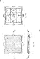
Figure 1 shows respectively a schematic top view, a section view along section 2-2' and a section view along section 1-1' of a manhole comprising a device for safety closing and locking the manhole, according to the invention; - -
Figure 2 shows a top view and two side views of the manhole comprising a device for safety closing and locking the manhole, according to the invention; - -
Figure 3 shows schematic section views and perspective views of the device for safety closing and locking the manhole, according to the invention; - -
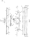
Figure 4 shows schematic views and section views of the frame of the manhole comprising a device for safety closing and locking the manhole, according to the invention; - -
Figure 5 shows the main section of the assembly manhole -frame comprising the device for safety closing and locking the manhole, according to the invention; - -
Figure 6 shows a detailed view of the device for safety closing and locking the manhole and of the coupled anti-theft bolt, according to the invention; - -
Figures 7a, 7b show a schematic section view of the work-key for closing in work position of the device for safety closing and locking the manhole and the main section views of the work-key, according to the invention; - -
Figures 8a, 8b show the anti-theft bolts used respectively for blocking the manhole to a cylinder comprised in the manhole and for the coupling to the block burglary, according to the invention; - -
Figures 9a, 9b show the cover comprising a device for safety closing and locking the manhole respectively in a closing position and in an opening position, according to the invention; - -
Figure 10 shows an exploded view of the manhole comprising a device for safety closing and locking the manhole, according to the invention. - With reference to those figures and, in particular, to the
figures 5 ,6 and10 , amanhole 50 comprising a device for safety closing and locking the manhole is shown, according to the invention. In particular, themanhole 50 comprising a device for safety closing and locking the manhole comprises a cover 4, for example made of cast iron, provided, in the lower portion, with threaded holes, in variable number depending on the size of themanhole 50. - The cover 4 comprise a central hole closed by a
lid 5, for example made of cast iron, whose closing edge is provided with a groove as a seat of a synthetic material gasket 11 acting as hermetic and waterproof closure to avoid infiltration of external liquids. - The
lid 5 is locked by means of anantitheft bolt 3 tightened into the threaded seat of a dice 6 having a round head, welded to alower slab 8, mating with an anti-burglary block 1 by means of alocation groove 5a, realized on the lower base of thelid 5, which defines the centering and blocks the rotation. - Advantageously according to the invention, the
bolt 3 constitutes a first security element of the closure device, being of a burglar type, difficult to be unscrewed without using an authorized key. Thisbolt 3 can be of appropriate design, size and with the strength of materials classes, treatments and surface coatings according to application needs. In this case, anti-theft bolts are encoded and only be loosened with the encoded and personalized key, available in exclusive form to the purchaser or to the person responsible for the closure device, ensuring maximum privacy and secrecy of the code. -
Other bolts 14 can be inserted in the threaded holes of the cover 4 to mount a circularcast iron support 13, shaped to allow the coupling and maneuvering of a device for safety closing themanhole 50. - According to an aspect of the invention, the device for safety closing the
manhole 50 is made of stainless steel. - According to another aspect of the invention, the safety closure device comprises a stainless steel cylinder 7 closed on the lower base and surmounted by a
circular crown 9, also made of stainless steel, welded near the upper end of the cylinder along a peripheral edge of thecrown 9. The lower base of the cylinder 7 is closed, by means of welding, by thestainless steel slab 8 having a square shape having vertices provided with holeshousing supporting pins 20 configured to supportlocking rods 18. - According to an aspect of the invention, the
locking rods 18 are made of stainless steel smooth rods having a diameter optimized to allow adequate resistance to the stresses caused by improper forcing attempts. - The
locking rods 18 are welded toplates 19 configured to connect thelocking rods 18 to theslab 8 by means of thepins 20, having a circular head. - According to another aspect of the invention, the
locking rods 18 are well connected to theslab 8 by means of abronze washer 21 to ensure the perfect height alignment of thelocking rods 18 with the axes ofholes washer 22 and acotter pin 23. Eachlocking rod 18 can then rotate around the axes of thepins 20. Thus, a rotation of theslab 8 around a main axis of rotation "a-a" of themanhole 50 imparts a roto-translational movement to eachlocking rod 18, allowing to advance toward or to retreat fromslotted guide holes 27 provided in theedges holes 26 provided in the supporting frame, allowing the closing or opening of themanhole 50. - The volume delimited by the walls of the cylinder 7 constitutes the housing of the main element of the closure device, constituted by the anti-burglary block 1, which represents the heart of the whole system and the fundamental part of the invention.
- Unscrewing the
safety bolt 3 and extracting thelid 5, it's possible to access to the anti-burglary block 1, for example made of stainless steel or other metal alloys with high mechanical characteristics. - According to an aspect of the invention, the anti-burglary block 1 has a thickness equal to the height of the cylindrical housing, a curve lateral surface having curvature radius perfectly adaptable to the internal lateral surface of the cylinder, shape and contour devoid of corners and grooves which could offer the possibilities of using levers or burglary tools. In the working position inside the cylindrical volume, the anti-burglary block 1 has the front side facing the center of the cylinder and it is provided with a
hole 2a to house a secondanti-theft bolt 2 realized ad hoc and robust to tentative burglary. Thehole 2a passes through the entire anti-burglary block 1 and has a greater diameter on the front side, in order to allow the insertion of theanti-theft bolt 2 and of a specific key. Instead, on the surface in contact with the cylindrical wall, the hole dimensions are equal to the nominal diameter of the anti-theft bolt plus or minus the tolerance values. The dimensions and the depth of the seat of theantitheft bolt 2a are designed to guarantee the mechanical resistance and, at the same time, to place the head of the anti-theft bolt more inside the anti-burglary block to make it not visible and not accessible without the specific codified key. - The
bolts bolt 2 is provided with a cylindrical hollow head in order to allow a smaller occupancy of the anti-theft key, further increasing the safety of the device. Thus, it's important to increase the depth of the housing of thebolt 2 in thehole 2a, by reducing as much as possible the diameter of saidhole 2a. In this way, theanti-theft bolt 2 is inaccessible and cannot be disassembled without the proper codified key. - The
anti-theft bolt 2 is screwed into a threadedspot 16 formed in the wall of the cylinder 7 and, to complete clamping, thanks to the end shape of the stem, smooth and tapered, it is housed in a locking hole 15 realized in a protrusion 13' of the circularcast iron support 13, the latter integral to themanhole 50 by means of its bolt junction. Therefore, the mainanti-theft bolt 2, completely screwed into its seat, achieves the locking of the device in the closed position, in the maximum extension of thelocking rods 18 in theircorrespondent housings 26. - Therefore, the opening of the
manhole 50 necessarily requires the removal of the anti-burglary block 1 unscrewing theanti-theft bolt 2 by means of the special codified key. - The
manhole 50 comprises centeringpins 17 and 17'. Removing the anti-burglary block 1 makes allowable thepin 17 which is predisposed for the application of anoperating key 29 of the closure device, as shown infigure 7 , by means of which it is possible to impart a rotation to the device by leveraging on the centeringpins 17 and 17'. In fact, imparting a rotation in a clockwise direction to thekey 29 generates a couple of forces whose resultant act on thepins 17 and 17', producing the rotation of the assembly cylinder-lower sheet. Therefore, the roto-translatory movement of thelocking rods 18 which, at that stage, withdraw from their seats allowing the opening of the manhole. TheFig. 9 shows the closure device respectively in the closed position (Fig. 9a ) and in the open position (Fig. 9b ). - The phase of closing and locking the
manhole 50 involves the counterclockwise rotation of the closing device by means of thesame key 29 and, subsequently, the insertion of the anti-burglary block 1, whose correct position is determined by the presence of thepin 17 acting as centering element. - On the lower base of the anti-burglary block 1 there is a
slot 1a within which the centering pin is inserted. When the anti-burglary block fits with its seat, theanti-theft bolt 2 is inserted and screwed till to the end of run within the locking hole 15 tightening it by means of the appropriate codified key. The keys necessary to unscrew theantitheft bolts - The angle of opening and of closure of the device is calculated in an exact manner as a function of the size and geometry of the manhole to which it is applied. For this purpose, an opening and closing
lock 35, shown inFigures 1 and9 , requires the maximum turning angle calculated at the design stage. - The
manhole 50 comprisesreinforcement ribs 28 to make themanhole 50 more robust, as illustrated inFigure 5 . - The closing device is designed to facilitate the movement and removal of the manhole from the support frame. For this reason, the
metal slab 8 of the closure device does not project beyond the maximum height of theribs 28 and of the cast iron edges of themanhole 50 to allow the removal of themanhole 50 from the seat of the frame. In particular, during removal, themanhole 50 can be dragged allowing it slides on theedge 24", shown inFigures 5 and10 , of the frame without obstacles. For this reason, both a threaded bolt 6 and pins 20 are provided with a round head, to create as little friction as possible and do not constitute barriers to the slippage of themanhole 50 on the edge of the frame. Alternatively, both thepins 20 and the threaded bolt 6 can be chosen with a countersunk head or directly welded to the lower surface of theslab 8, so as do not produce protrusions. - According to an aspect of the invention, the peripheral edges of the
manhole 50, as shown inFigures 1 , 32 and 33, that can be made in a single block of iron casting together with the upper cover 4 and theribs 28, are designed not only to for giving structural robustness but also to provide greater ease of removal of the manhole from the seat of the frame. The verticalperipheral edges 33 in addition to having a structural function have also the function of allowing the slippage of the manhole on theframe edge 24" shown inFigures 5 and10 : the manhole can be opportunely relieved from the seat only on one side of a minimum amount equal to the thickness of the cover 4, and dragged by sliding on the edge of the frame. The twoedges 32, orthogonal to the preceding, are inclined by an angle such as to allow both the support on the frame and both for facilitate the removal of the manhole from the seat of the frame. Consequently, thevertical edges 33 are chamfered at the ends by an angle equal to the inclination of the inclined edges 32. - The manhole described is realized in a way do not allow infiltration of liquids from the outside, safeguarding, in particular, the volume inside the cylinder 7 of the safety closure device, protecting the anti-burglary block and the anti-theft bolt from corrosion or fouling caused by possible infiltrations. For this purpose, the
manhole 50 comprises agasket 11 shown inFigure 6 on the closing edge of theupper lid 5 made of cast iron, awasher 12 shown inFigure 6 made of synthetic material under the head of theanti-theft bolt 3 of thelid 5 and a gasket made of synthetic material applied over a gasket having acircular support crown 10 shown inFigure 6 in contact with the lower surface of the cover 4. Thelatter gasket 10 is connected with tolerance to the lower plane of the cover 4 when thesafety bolt 3 of thelid 5 is loosened, allowing the cylinder 7 rotates during opening and closing operations of the manhole, while it is tightly in contact with the lower plane of the cover 4 following the tightening of thesafety bolt 3 of thelid 5; at the same time, also the seal of thelid 5 ensures the hermetic closure between its contact surfaces. Finally, also the supporting frame of the manhole, shown inFigure 4 , made in cast iron or other metal alloys, presents a peripheral housing for thegasket 25, shown inFigures 5 and10 , thus preventing seepage of liquids from the outside towards the inside of the enclosed generic compartment or leaking of any unpleasant odors into the outside environment. The gasket of theframe 25 is also anti-noisy for the passage of vehicles preventing collisions between metal parts. Thegasket washer - The manhole here described can be applied to safety close wells, aqueducts, sewers, wells service of electrical and telephone lines, and hatches in general.
- According to the invention, the manhole can be spheroidal or laminated or of square shape.
- Furthermore, according to an aspect of the invention, the manhole can be made of steel, or of carbon or of stainless steel, or of cast iron or different types of metallic alloys.
- All the components of the invention are realizable or by the melting process or by machining and assembly in the factory and, in general, with the methods and equipment usually employed in the common construction practice.
- Advantageously according to the invention, it's not necessary a particular maintenance for the
manhole 50. - Advantageously according to the invention, the
manhole 50 is easily realized and used. - Advantageously according to the invention, the manhole is low cost.
- Finally it is clear that the manhole comprising a device for safety closing and locking the manhole described and illustrated here can be modified and varied without departing from the protective scope of the present invention, as defined in the appended claims.
Claims (10)
- A manhole (50) comprising a device for safety closing and locking the manhole (50), comprising a cylinder (7), attached to a slab (8) which comprises centering pins (17, 17'), the cylinder (7) being able to rotate around an axis a-a' by the action of an operating key (29) acting on the pins (17, 17'), the manhole (50) further comprising at least one "anti-burglary block" (1), which in the locked position is positioned inside the cylinder (7) by means of one of the centering pins (17, 17'), said block (1) having a thickness equal to the height of the cylinder (7) and a curved surface in order to be adaptable to the inner wall of the cylinder (7), whose function is to hide and protect an anti-theft bolt (2) inside a hole (2a), which crosses the whole anti-burglary block (1), said hole (2a) having a larger diameter at the front and a diameter equal to the nominal diameter of the anti-theft bolt (2) in the back which supports the inner wall of the cylinder itself (7) having a tightening threaded spot (16) able to allow the placement of the anti-theft bolt (2) in the depth of the body of the anti-burglary block (1) in total tightening conditions into the threaded spot (16), wherein the end of the anti-theft bolt (2), in the closed position, is housed in a locking hole (15) on a circular support (13) of the manhole cover (4).
- A manhole (50) comprising a device for safety closing and locking the manhole (50) according to claim 1, characterized in comprising a plurality of anti-burglary blocks (1), contained within the cylinder (7).
- A manhole (50) comprising a device for safety closing and locking the manhole (50) according to claims 1 and 2, characterized in that the anti-theft bolt (2) is provided with a hollow cylindrical encoded head.
- A manhole (50) comprising a device for safety closing and locking the manhole (50) according to claim 1, characterized in comprising a further anti-theft bolt (3) tightened into the threaded seat of a dice (6) having a round head, welded to the slab (8) and a lid (5) mating with the anti- burglary block (1) by means of a location groove (5a), realized on the lower base of the lid (5), which defines the centering and blocks the rotation.
- A manhole (50) comprising a device for safety closing and locking the manhole (50) according to claim 1, characterized in that the cylinder (7) is surmounted by a circular crown (9) and is closed on the base, by means of welding, by the slab (8) .
- A manhole (50) comprising a device for safety closing and locking the manhole (50) according to claim 1, characterized in that the slab (8) is squared shaped having vertices provided with holes housing supporting pins (20) configured to support locking rods (18), able to rotate around the axis a-a' by the maximum maneuver angle delimited by a lock (35), by the action of an operating key (29) which acts on the pins (17, 17') allowing the roto-translatory movement of the locking rods (18) in the positions of opening and closing in seats (26) of the frame.
- A manhole (50) comprising a device for safety closing and locking the manhole (50) according to claims 1, 4 and 5, characterized in comprising a gasket (10) applied over the circular crown (9) and in connection with the lower plane of the cover (4) comprising a central hole closed by the lid (5) when the anti-theft bolt (3) is loosened, a gasket (11) of the lid (5) and a washer (12) of the bolt (3).
- A manhole (50) comprising a device for safety closing and locking the manhole (50) according to claims 1 and 6, characterized in that the circular support (13) connected to the cover (4) is provided with a protrusion (13') comprising the locking hole (15) .
- A manhole (50) comprising a device for safety closing and locking the manhole (50) according to claim 1 and 6, characterized in that the locking rods (18) are connected to the slab (8) by means of at least one washer (22), at least one alignment washer (21) and at least one cotter pin (23), capable of roto-translating in guide holes (27).
- A manhole (50) comprising a device for safety closing and locking the manhole (50) according to claim 1, characterized in comprising two vertical edges (33), parallel and chamfered, and two edges (32) inclined by the angle of chamfering of the previous edges, provided with guide slotted holes (27) allowing the slippage of the manhole on the frame edge (24").
Applications Claiming Priority (2)
| Application Number | Priority Date | Filing Date | Title |
|---|---|---|---|
| ITUB2015A003926A ITUB20153926A1 (en) | 2015-09-14 | 2015-09-14 | SECURITY CLOSING AND LOCKING DEVICE FOR A FRAME |
| PCT/IB2016/055440 WO2017046696A1 (en) | 2015-09-14 | 2016-09-13 | Manhole comprising a device for safety closing and locking the manhole |
Publications (2)
| Publication Number | Publication Date |
|---|---|
| EP3350376A1 EP3350376A1 (en) | 2018-07-25 |
| EP3350376B1 true EP3350376B1 (en) | 2020-12-16 |
Family
ID=55697275
Family Applications (1)
| Application Number | Title | Priority Date | Filing Date |
|---|---|---|---|
| EP16785262.3A Active EP3350376B1 (en) | 2015-09-14 | 2016-09-13 | Manhole comprising a device for safety closing and locking the manhole |
Country Status (7)
| Country | Link |
|---|---|
| US (1) | US10550540B2 (en) |
| EP (1) | EP3350376B1 (en) |
| CN (1) | CN108291379A (en) |
| CA (1) | CA2998570A1 (en) |
| EA (1) | EA033802B1 (en) |
| IT (1) | ITUB20153926A1 (en) |
| WO (1) | WO2017046696A1 (en) |
Families Citing this family (8)
| Publication number | Priority date | Publication date | Assignee | Title |
|---|---|---|---|---|
| WO2018089251A1 (en) * | 2016-11-14 | 2018-05-17 | Hubbell Incorporated | Latch locking cover for enclosures |
| US11118323B1 (en) * | 2017-06-05 | 2021-09-14 | David Putnam | Traffic-compatible vented precipitation guarding manhole cover assemblies |
| FR3080093B1 (en) * | 2018-04-17 | 2021-08-27 | Atechsys Eng Ate | INTER-LOCKING SYSTEM AND AUTONOMOUS OBJECT TRANSPORT SYSTEM |
| IT201800009233A1 (en) * | 2018-10-08 | 2020-04-08 | Dsg Srl | Well closing device or similar |
| IT201800011019A1 (en) | 2018-12-12 | 2020-06-12 | Dsg S R L | Well closing device or similar |
| CN110552373B (en) * | 2019-08-29 | 2020-06-16 | 南京达蓝自动化科技有限公司 | Rotary manhole cover anti-theft mechanism and operation method |
| CN111827797B (en) * | 2020-07-25 | 2021-11-23 | 深圳市零比特科技开发有限公司 | Intelligent household door lock |
| CH718074A1 (en) * | 2020-11-18 | 2022-05-31 | Renggli Werner | Blocking unit for a manhole structure that can be closed with a manhole cover. |
Family Cites Families (16)
| Publication number | Priority date | Publication date | Assignee | Title |
|---|---|---|---|---|
| US845182A (en) * | 1906-05-31 | 1907-02-26 | Benjamin T Letts | Lock for manhole-covers. |
| US2057866A (en) * | 1936-06-12 | 1936-10-20 | Laclede Stoker Company | Fastening device for manhole covers |
| US2363567A (en) * | 1943-06-12 | 1944-11-28 | Henry W Blakeman | Cover plate |
| US4964755A (en) * | 1989-04-18 | 1990-10-23 | Lew-Mor, Inc. | Manhole cover lock apparatus |
| US5033696A (en) * | 1989-12-15 | 1991-07-23 | Rockwell International Corporation | Flush mounted hatch opener |
| US6739796B1 (en) * | 2003-03-21 | 2004-05-25 | Philip W. Del Nero | High security manhole insert cover |
| FR2892752B1 (en) * | 2005-10-27 | 2009-01-16 | Norinco Soc Par Actions Simpli | DEVICE FOR SECURELY LOCKING A BUFFER OR COVERING A FRAME, ESPECIALLY GROUNDING LOOK |
| US7798742B2 (en) * | 2007-04-18 | 2010-09-21 | Mcgard, Llc | Security key tool for manhole access opening security device |
| DE102008057023B4 (en) * | 2008-11-12 | 2011-09-22 | Lic Langmatz Gmbh | Safety arrangement for a manhole cover |
| CN203247607U (en) * | 2012-04-16 | 2013-10-23 | 广州智天电子科技有限公司 | Wireless power supply communication technology-based wireless well lid device |
| CN203238670U (en) * | 2013-05-27 | 2013-10-16 | 湖北汽车工业学院 | Anti-theft device for inspection well |
| US9416516B2 (en) * | 2014-08-22 | 2016-08-16 | Neenah Foundry Company | Pressure responsive locking latch arrangement for manhole covers |
| GB2542506B (en) * | 2015-09-17 | 2021-03-24 | Neenah Foundry Company | Manhole cover assembly |
| GB2543642B (en) * | 2015-09-17 | 2021-01-20 | Neenah Foundry Company | Manhole cover assembly |
| US10294627B2 (en) * | 2017-02-03 | 2019-05-21 | Opw Fueling Components, Llc | Sump backfill protector |
| US20180274198A1 (en) * | 2017-03-24 | 2018-09-27 | John M. Finn | Device for Securing Covers of Drainage Holes and the Like |
-
2015
- 2015-09-14 IT ITUB2015A003926A patent/ITUB20153926A1/en unknown
-
2016
- 2016-09-13 WO PCT/IB2016/055440 patent/WO2017046696A1/en active Application Filing
- 2016-09-13 US US15/759,520 patent/US10550540B2/en active Active
- 2016-09-13 CN CN201680053424.1A patent/CN108291379A/en active Pending
- 2016-09-13 EA EA201890625A patent/EA033802B1/en not_active IP Right Cessation
- 2016-09-13 CA CA2998570A patent/CA2998570A1/en not_active Abandoned
- 2016-09-13 EP EP16785262.3A patent/EP3350376B1/en active Active
Non-Patent Citations (1)
| Title |
|---|
| None * |
Also Published As
| Publication number | Publication date |
|---|---|
| CN108291379A (en) | 2018-07-17 |
| EA201890625A1 (en) | 2018-10-31 |
| EP3350376A1 (en) | 2018-07-25 |
| CA2998570A1 (en) | 2017-03-23 |
| ITUB20153926A1 (en) | 2015-12-14 |
| WO2017046696A1 (en) | 2017-03-23 |
| US20190145079A1 (en) | 2019-05-16 |
| EA033802B1 (en) | 2019-11-27 |
| US10550540B2 (en) | 2020-02-04 |
Similar Documents
| Publication | Publication Date | Title |
|---|---|---|
| EP3350376B1 (en) | Manhole comprising a device for safety closing and locking the manhole | |
| US6739796B1 (en) | High security manhole insert cover | |
| US7201534B2 (en) | Apparatus and method to secure manhole accessways | |
| US4577478A (en) | Locking filler tube cover apparatus for underground fuel tanks | |
| US3453846A (en) | Padlock shackle guards | |
| EP3186461B1 (en) | Anti-vandalism padlock | |
| US20050103065A1 (en) | Protective cover for locking devices | |
| GB1597126A (en) | Door bolt devices | |
| US10519696B2 (en) | Padlock assembly with protective shield | |
| KR100688894B1 (en) | Multiroal Compression Manhole Cover | |
| KR200401652Y1 (en) | Locking structure of manhole cover | |
| US20210310210A1 (en) | Secured service cover assembly | |
| KR101556615B1 (en) | Assistance locking device for a manhole | |
| CN214615916U (en) | Door capable of preventing lock from being illegally opened or damaged | |
| EP3907112B1 (en) | Safety box for obd connectors | |
| CN111212952B (en) | Locking device | |
| GB2419156A (en) | Protected locking device | |
| WO2011044634A1 (en) | Security locking mechanism | |
| TW202411519A (en) | Hoop lock with welded-on armoring | |
| JP5707368B2 (en) | Lock protection device | |
| CN112502538A (en) | Door capable of preventing lock from being illegally opened or damaged | |
| JPS6040680Y2 (en) | Locking device for manhole covers etc. | |
| CA1247877A (en) | Locking filler tube cover apparatus for underground fuel tanks | |
| WO2017034430A1 (en) | Lock | |
| WO2016133418A1 (en) | Mechanism with a chain for preventing theft of street drain cover |
Legal Events
| Date | Code | Title | Description |
|---|---|---|---|
| STAA | Information on the status of an ep patent application or granted ep patent |
Free format text: STATUS: UNKNOWN |
|
| STAA | Information on the status of an ep patent application or granted ep patent |
Free format text: STATUS: THE INTERNATIONAL PUBLICATION HAS BEEN MADE |
|
| PUAI | Public reference made under article 153(3) epc to a published international application that has entered the european phase |
Free format text: ORIGINAL CODE: 0009012 |
|
| STAA | Information on the status of an ep patent application or granted ep patent |
Free format text: STATUS: REQUEST FOR EXAMINATION WAS MADE |
|
| 17P | Request for examination filed |
Effective date: 20180315 |
|
| AK | Designated contracting states |
Kind code of ref document: A1 Designated state(s): AL AT BE BG CH CY CZ DE DK EE ES FI FR GB GR HR HU IE IS IT LI LT LU LV MC MK MT NL NO PL PT RO RS SE SI SK SM TR |
|
| AX | Request for extension of the european patent |
Extension state: BA ME |
|
| DAV | Request for validation of the european patent (deleted) | ||
| DAX | Request for extension of the european patent (deleted) | ||
| GRAP | Despatch of communication of intention to grant a patent |
Free format text: ORIGINAL CODE: EPIDOSNIGR1 |
|
| STAA | Information on the status of an ep patent application or granted ep patent |
Free format text: STATUS: GRANT OF PATENT IS INTENDED |
|
| INTG | Intention to grant announced |
Effective date: 20200717 |
|
| GRAS | Grant fee paid |
Free format text: ORIGINAL CODE: EPIDOSNIGR3 |
|
| GRAA | (expected) grant |
Free format text: ORIGINAL CODE: 0009210 |
|
| STAA | Information on the status of an ep patent application or granted ep patent |
Free format text: STATUS: THE PATENT HAS BEEN GRANTED |
|
| AK | Designated contracting states |
Kind code of ref document: B1 Designated state(s): AL AT BE BG CH CY CZ DE DK EE ES FI FR GB GR HR HU IE IS IT LI LT LU LV MC MK MT NL NO PL PT RO RS SE SI SK SM TR |
|
| REG | Reference to a national code |
Ref country code: GB Ref legal event code: FG4D |
|
| REG | Reference to a national code |
Ref country code: IE Ref legal event code: FG4D |
|
| REG | Reference to a national code |
Ref country code: DE Ref legal event code: R096 Ref document number: 602016049939 Country of ref document: DE |
|
| REG | Reference to a national code |
Ref country code: AT Ref legal event code: REF Ref document number: 1345721 Country of ref document: AT Kind code of ref document: T Effective date: 20210115 |
|
| PG25 | Lapsed in a contracting state [announced via postgrant information from national office to epo] |
Ref country code: GR Free format text: LAPSE BECAUSE OF FAILURE TO SUBMIT A TRANSLATION OF THE DESCRIPTION OR TO PAY THE FEE WITHIN THE PRESCRIBED TIME-LIMIT Effective date: 20210317 Ref country code: FI Free format text: LAPSE BECAUSE OF FAILURE TO SUBMIT A TRANSLATION OF THE DESCRIPTION OR TO PAY THE FEE WITHIN THE PRESCRIBED TIME-LIMIT Effective date: 20201216 Ref country code: NO Free format text: LAPSE BECAUSE OF FAILURE TO SUBMIT A TRANSLATION OF THE DESCRIPTION OR TO PAY THE FEE WITHIN THE PRESCRIBED TIME-LIMIT Effective date: 20210316 Ref country code: RS Free format text: LAPSE BECAUSE OF FAILURE TO SUBMIT A TRANSLATION OF THE DESCRIPTION OR TO PAY THE FEE WITHIN THE PRESCRIBED TIME-LIMIT Effective date: 20201216 |
|
| REG | Reference to a national code |
Ref country code: AT Ref legal event code: MK05 Ref document number: 1345721 Country of ref document: AT Kind code of ref document: T Effective date: 20201216 |
|
| REG | Reference to a national code |
Ref country code: NL Ref legal event code: MP Effective date: 20201216 |
|
| PG25 | Lapsed in a contracting state [announced via postgrant information from national office to epo] |
Ref country code: SE Free format text: LAPSE BECAUSE OF FAILURE TO SUBMIT A TRANSLATION OF THE DESCRIPTION OR TO PAY THE FEE WITHIN THE PRESCRIBED TIME-LIMIT Effective date: 20201216 Ref country code: BG Free format text: LAPSE BECAUSE OF FAILURE TO SUBMIT A TRANSLATION OF THE DESCRIPTION OR TO PAY THE FEE WITHIN THE PRESCRIBED TIME-LIMIT Effective date: 20210316 Ref country code: LV Free format text: LAPSE BECAUSE OF FAILURE TO SUBMIT A TRANSLATION OF THE DESCRIPTION OR TO PAY THE FEE WITHIN THE PRESCRIBED TIME-LIMIT Effective date: 20201216 |
|
| PG25 | Lapsed in a contracting state [announced via postgrant information from national office to epo] |
Ref country code: NL Free format text: LAPSE BECAUSE OF FAILURE TO SUBMIT A TRANSLATION OF THE DESCRIPTION OR TO PAY THE FEE WITHIN THE PRESCRIBED TIME-LIMIT Effective date: 20201216 Ref country code: HR Free format text: LAPSE BECAUSE OF FAILURE TO SUBMIT A TRANSLATION OF THE DESCRIPTION OR TO PAY THE FEE WITHIN THE PRESCRIBED TIME-LIMIT Effective date: 20201216 |
|
| REG | Reference to a national code |
Ref country code: LT Ref legal event code: MG9D |
|
| PG25 | Lapsed in a contracting state [announced via postgrant information from national office to epo] |
Ref country code: SK Free format text: LAPSE BECAUSE OF FAILURE TO SUBMIT A TRANSLATION OF THE DESCRIPTION OR TO PAY THE FEE WITHIN THE PRESCRIBED TIME-LIMIT Effective date: 20201216 Ref country code: PT Free format text: LAPSE BECAUSE OF FAILURE TO SUBMIT A TRANSLATION OF THE DESCRIPTION OR TO PAY THE FEE WITHIN THE PRESCRIBED TIME-LIMIT Effective date: 20210416 Ref country code: RO Free format text: LAPSE BECAUSE OF FAILURE TO SUBMIT A TRANSLATION OF THE DESCRIPTION OR TO PAY THE FEE WITHIN THE PRESCRIBED TIME-LIMIT Effective date: 20201216 Ref country code: CZ Free format text: LAPSE BECAUSE OF FAILURE TO SUBMIT A TRANSLATION OF THE DESCRIPTION OR TO PAY THE FEE WITHIN THE PRESCRIBED TIME-LIMIT Effective date: 20201216 Ref country code: EE Free format text: LAPSE BECAUSE OF FAILURE TO SUBMIT A TRANSLATION OF THE DESCRIPTION OR TO PAY THE FEE WITHIN THE PRESCRIBED TIME-LIMIT Effective date: 20201216 Ref country code: SM Free format text: LAPSE BECAUSE OF FAILURE TO SUBMIT A TRANSLATION OF THE DESCRIPTION OR TO PAY THE FEE WITHIN THE PRESCRIBED TIME-LIMIT Effective date: 20201216 Ref country code: LT Free format text: LAPSE BECAUSE OF FAILURE TO SUBMIT A TRANSLATION OF THE DESCRIPTION OR TO PAY THE FEE WITHIN THE PRESCRIBED TIME-LIMIT Effective date: 20201216 |
|
| PG25 | Lapsed in a contracting state [announced via postgrant information from national office to epo] |
Ref country code: PL Free format text: LAPSE BECAUSE OF FAILURE TO SUBMIT A TRANSLATION OF THE DESCRIPTION OR TO PAY THE FEE WITHIN THE PRESCRIBED TIME-LIMIT Effective date: 20201216 Ref country code: AT Free format text: LAPSE BECAUSE OF FAILURE TO SUBMIT A TRANSLATION OF THE DESCRIPTION OR TO PAY THE FEE WITHIN THE PRESCRIBED TIME-LIMIT Effective date: 20201216 |
|
| REG | Reference to a national code |
Ref country code: DE Ref legal event code: R097 Ref document number: 602016049939 Country of ref document: DE |
|
| PG25 | Lapsed in a contracting state [announced via postgrant information from national office to epo] |
Ref country code: IS Free format text: LAPSE BECAUSE OF FAILURE TO SUBMIT A TRANSLATION OF THE DESCRIPTION OR TO PAY THE FEE WITHIN THE PRESCRIBED TIME-LIMIT Effective date: 20210416 |
|
| PLBE | No opposition filed within time limit |
Free format text: ORIGINAL CODE: 0009261 |
|
| STAA | Information on the status of an ep patent application or granted ep patent |
Free format text: STATUS: NO OPPOSITION FILED WITHIN TIME LIMIT |
|
| PG25 | Lapsed in a contracting state [announced via postgrant information from national office to epo] |
Ref country code: AL Free format text: LAPSE BECAUSE OF FAILURE TO SUBMIT A TRANSLATION OF THE DESCRIPTION OR TO PAY THE FEE WITHIN THE PRESCRIBED TIME-LIMIT Effective date: 20201216 Ref country code: IT Free format text: LAPSE BECAUSE OF FAILURE TO SUBMIT A TRANSLATION OF THE DESCRIPTION OR TO PAY THE FEE WITHIN THE PRESCRIBED TIME-LIMIT Effective date: 20201216 |
|
| 26N | No opposition filed |
Effective date: 20210917 |
|
| PG25 | Lapsed in a contracting state [announced via postgrant information from national office to epo] |
Ref country code: DK Free format text: LAPSE BECAUSE OF FAILURE TO SUBMIT A TRANSLATION OF THE DESCRIPTION OR TO PAY THE FEE WITHIN THE PRESCRIBED TIME-LIMIT Effective date: 20201216 |
|
| PG25 | Lapsed in a contracting state [announced via postgrant information from national office to epo] |
Ref country code: ES Free format text: LAPSE BECAUSE OF FAILURE TO SUBMIT A TRANSLATION OF THE DESCRIPTION OR TO PAY THE FEE WITHIN THE PRESCRIBED TIME-LIMIT Effective date: 20201216 |
|
| PG25 | Lapsed in a contracting state [announced via postgrant information from national office to epo] |
Ref country code: SI Free format text: LAPSE BECAUSE OF FAILURE TO SUBMIT A TRANSLATION OF THE DESCRIPTION OR TO PAY THE FEE WITHIN THE PRESCRIBED TIME-LIMIT Effective date: 20201216 |
|
| PG25 | Lapsed in a contracting state [announced via postgrant information from national office to epo] |
Ref country code: IS Free format text: LAPSE BECAUSE OF FAILURE TO SUBMIT A TRANSLATION OF THE DESCRIPTION OR TO PAY THE FEE WITHIN THE PRESCRIBED TIME-LIMIT Effective date: 20210416 |
|
| PG25 | Lapsed in a contracting state [announced via postgrant information from national office to epo] |
Ref country code: IE Free format text: LAPSE BECAUSE OF NON-PAYMENT OF DUE FEES Effective date: 20210913 |
|
| PG25 | Lapsed in a contracting state [announced via postgrant information from national office to epo] |
Ref country code: HU Free format text: LAPSE BECAUSE OF FAILURE TO SUBMIT A TRANSLATION OF THE DESCRIPTION OR TO PAY THE FEE WITHIN THE PRESCRIBED TIME-LIMIT; INVALID AB INITIO Effective date: 20160913 |
|
| P01 | Opt-out of the competence of the unified patent court (upc) registered |
Effective date: 20230518 |
|
| PG25 | Lapsed in a contracting state [announced via postgrant information from national office to epo] |
Ref country code: CY Free format text: LAPSE BECAUSE OF FAILURE TO SUBMIT A TRANSLATION OF THE DESCRIPTION OR TO PAY THE FEE WITHIN THE PRESCRIBED TIME-LIMIT Effective date: 20201216 |
|
| PGFP | Annual fee paid to national office [announced via postgrant information from national office to epo] |
Ref country code: LU Payment date: 20230801 Year of fee payment: 8 |
|
| PGFP | Annual fee paid to national office [announced via postgrant information from national office to epo] |
Ref country code: MC Payment date: 20230802 Year of fee payment: 8 Ref country code: GB Payment date: 20230727 Year of fee payment: 8 |
|
| PGFP | Annual fee paid to national office [announced via postgrant information from national office to epo] |
Ref country code: FR Payment date: 20230727 Year of fee payment: 8 Ref country code: DE Payment date: 20230801 Year of fee payment: 8 Ref country code: BE Payment date: 20230801 Year of fee payment: 8 |
|
| PGFP | Annual fee paid to national office [announced via postgrant information from national office to epo] |
Ref country code: CH Payment date: 20231001 Year of fee payment: 8 |