EP3350086B1 - Récipient pour produits de consommation à action de fermeture de couvercle liss - Google Patents
Récipient pour produits de consommation à action de fermeture de couvercle liss Download PDFInfo
- Publication number
- EP3350086B1 EP3350086B1 EP16766312.9A EP16766312A EP3350086B1 EP 3350086 B1 EP3350086 B1 EP 3350086B1 EP 16766312 A EP16766312 A EP 16766312A EP 3350086 B1 EP3350086 B1 EP 3350086B1
- Authority
- EP
- European Patent Office
- Prior art keywords
- inner frame
- container
- line
- lid
- cut
- Prior art date
- Legal status (The legal status is an assumption and is not a legal conclusion. Google has not performed a legal analysis and makes no representation as to the accuracy of the status listed.)
- Not-in-force
Links
Images

Classifications
-
- B—PERFORMING OPERATIONS; TRANSPORTING
- B65—CONVEYING; PACKING; STORING; HANDLING THIN OR FILAMENTARY MATERIAL
- B65D—CONTAINERS FOR STORAGE OR TRANSPORT OF ARTICLES OR MATERIALS, e.g. BAGS, BARRELS, BOTTLES, BOXES, CANS, CARTONS, CRATES, DRUMS, JARS, TANKS, HOPPERS, FORWARDING CONTAINERS; ACCESSORIES, CLOSURES, OR FITTINGS THEREFOR; PACKAGING ELEMENTS; PACKAGES
- B65D85/00—Containers, packaging elements or packages, specially adapted for particular articles or materials
- B65D85/07—Containers, packaging elements or packages, specially adapted for particular articles or materials for compressible or flexible articles
- B65D85/08—Containers, packaging elements or packages, specially adapted for particular articles or materials for compressible or flexible articles rod-shaped or tubular
- B65D85/10—Containers, packaging elements or packages, specially adapted for particular articles or materials for compressible or flexible articles rod-shaped or tubular for cigarettes
- B65D85/1036—Containers formed by erecting a rigid or semi-rigid blank
- B65D85/1045—Containers formed by erecting a rigid or semi-rigid blank having a cap-like lid hinged to an edge
-
- A—HUMAN NECESSITIES
- A24—TOBACCO; CIGARS; CIGARETTES; SIMULATED SMOKING DEVICES; SMOKERS' REQUISITES
- A24F—SMOKERS' REQUISITES; MATCH BOXES; SIMULATED SMOKING DEVICES
- A24F15/00—Receptacles or boxes specially adapted for cigars, cigarettes, simulated smoking devices or cigarettes therefor
- A24F15/12—Receptacles or boxes specially adapted for cigars, cigarettes, simulated smoking devices or cigarettes therefor for pocket use
-
- B—PERFORMING OPERATIONS; TRANSPORTING
- B65—CONVEYING; PACKING; STORING; HANDLING THIN OR FILAMENTARY MATERIAL
- B65D—CONTAINERS FOR STORAGE OR TRANSPORT OF ARTICLES OR MATERIALS, e.g. BAGS, BARRELS, BOTTLES, BOXES, CANS, CARTONS, CRATES, DRUMS, JARS, TANKS, HOPPERS, FORWARDING CONTAINERS; ACCESSORIES, CLOSURES, OR FITTINGS THEREFOR; PACKAGING ELEMENTS; PACKAGES
- B65D5/00—Rigid or semi-rigid containers of polygonal cross-section, e.g. boxes, cartons or trays, formed by folding or erecting one or more blanks made of paper
- B65D5/42—Details of containers or of foldable or erectable container blanks
- B65D5/64—Lids
- B65D5/66—Hinged lids
- B65D5/6602—Hinged lids formed by folding one or more extensions hinged to the upper edge of a tubular container body
- B65D5/662—Hinged lids formed by folding one or more extensions hinged to the upper edge of a tubular container body the container being provided with an internal frame or the like for maintaining the lid in the closed position by friction
-
- B—PERFORMING OPERATIONS; TRANSPORTING
- B65—CONVEYING; PACKING; STORING; HANDLING THIN OR FILAMENTARY MATERIAL
- B65D—CONTAINERS FOR STORAGE OR TRANSPORT OF ARTICLES OR MATERIALS, e.g. BAGS, BARRELS, BOTTLES, BOXES, CANS, CARTONS, CRATES, DRUMS, JARS, TANKS, HOPPERS, FORWARDING CONTAINERS; ACCESSORIES, CLOSURES, OR FITTINGS THEREFOR; PACKAGING ELEMENTS; PACKAGES
- B65D5/00—Rigid or semi-rigid containers of polygonal cross-section, e.g. boxes, cartons or trays, formed by folding or erecting one or more blanks made of paper
- B65D5/42—Details of containers or of foldable or erectable container blanks
- B65D5/64—Lids
- B65D5/66—Hinged lids
- B65D5/6626—Hinged lids formed by folding extensions of a side panel of a container body formed by erecting a "cross-like" blank
- B65D5/6679—Hinged lids formed by folding extensions of a side panel of a container body formed by erecting a "cross-like" blank the container being provided with an internal frame or the like for maintaining the lid in the closed position by friction
-
- B—PERFORMING OPERATIONS; TRANSPORTING
- B65—CONVEYING; PACKING; STORING; HANDLING THIN OR FILAMENTARY MATERIAL
- B65D—CONTAINERS FOR STORAGE OR TRANSPORT OF ARTICLES OR MATERIALS, e.g. BAGS, BARRELS, BOTTLES, BOXES, CANS, CARTONS, CRATES, DRUMS, JARS, TANKS, HOPPERS, FORWARDING CONTAINERS; ACCESSORIES, CLOSURES, OR FITTINGS THEREFOR; PACKAGING ELEMENTS; PACKAGES
- B65D5/00—Rigid or semi-rigid containers of polygonal cross-section, e.g. boxes, cartons or trays, formed by folding or erecting one or more blanks made of paper
- B65D5/42—Details of containers or of foldable or erectable container blanks
- B65D5/64—Lids
- B65D5/66—Hinged lids
- B65D5/6685—Hinged lids formed by extensions hinged to the upper edge of a container body formed by erecting a blank to U-shape
- B65D5/6691—Hinged lids formed by extensions hinged to the upper edge of a container body formed by erecting a blank to U-shape the container being provided with an internal frame or the like for maintaining the lid in the closed position by friction
-
- B—PERFORMING OPERATIONS; TRANSPORTING
- B65—CONVEYING; PACKING; STORING; HANDLING THIN OR FILAMENTARY MATERIAL
- B65D—CONTAINERS FOR STORAGE OR TRANSPORT OF ARTICLES OR MATERIALS, e.g. BAGS, BARRELS, BOTTLES, BOXES, CANS, CARTONS, CRATES, DRUMS, JARS, TANKS, HOPPERS, FORWARDING CONTAINERS; ACCESSORIES, CLOSURES, OR FITTINGS THEREFOR; PACKAGING ELEMENTS; PACKAGES
- B65D85/00—Containers, packaging elements or packages, specially adapted for particular articles or materials
- B65D85/07—Containers, packaging elements or packages, specially adapted for particular articles or materials for compressible or flexible articles
- B65D85/08—Containers, packaging elements or packages, specially adapted for particular articles or materials for compressible or flexible articles rod-shaped or tubular
- B65D85/10—Containers, packaging elements or packages, specially adapted for particular articles or materials for compressible or flexible articles rod-shaped or tubular for cigarettes
- B65D85/1036—Containers formed by erecting a rigid or semi-rigid blank
- B65D85/1045—Containers formed by erecting a rigid or semi-rigid blank having a cap-like lid hinged to an edge
- B65D85/1056—Containers formed by erecting a rigid or semi-rigid blank having a cap-like lid hinged to an edge characterized by the lid
Definitions
- the present invention relates to a container for consumer goods and to a blank for forming such container, which find particular application for holding consumer goods, such as smoking articles (for example cigarettes).
- Smoking articles are typically packaged in rigid hinge-lid containers formed from folded laminar blanks.
- elongate smoking articles such as cigarettes and cigars
- rigid hinged lid containers comprising a box portion and a lid connected to the box portion about a hinge line extending across a back wall of the container.
- the lid is pivotable about the hinge line between a closed position and an open position.
- Such containers are typically constructed from one-piece laminar cardboard blanks.
- One such container with a reinforcement frame mounted within the box portion.
- One such inner frame comprises a frame front wall, a portion of which extends beyond an upper edge of a front wall of the box portion. This improves the strength of the top portion of the container. Further, when the lid is in the closed position, the provision of one such inner frame makes it easy for the lid front to align with the box front wall. Thus, the container presents to the user a substantially flat front surface.
- WO 2011/054650 discloses a hinge lid package comprising an inner frame provided with tabs extending laterally from the inner frame front wall, the tabs being defined by cut lines in the inner frame side walls.
- Each cut line intersects a respective inner frame fold line along which the respective inner frame side wall depends from the inner frame front wall.
- slide-and-shell containers have been proposed that comprise tabs extending laterally from the slide portion and adapted to engage the inner surface of the side walls of the outer shell, such that it is easier to maintain the slide portion within the shell by frictional engagement.
- a container for consumer goods with an improved opening and closing mechanism, by which the overall quality and reliability of the container can be increased.
- a container for consumer articles comprising a box portion; a lid portion, wherein the lid portion is moveable about the hinge line between an open position and a closed position; and an inner frame received within the box portion.
- the inner frame comprises an inner frame front wall and first and second inner frame side walls each depending along an inner frame fold line from the inner frame front wall. Further, the inner frame comprises a first cut line and a second cut line in the first and second inner frame side walls, respectively, wherein each of the first and second cut lines intersects a respective inner frame fold line at upper and lower intersection points.
- the first and second cut lines define a first and a second locking tab.
- Each of the first and second locking tab extends outwardly from the inner frame towards a respective side wall of the container and past an edge formed by the inner frame front wall with a respective inner frame side wall, and interacts with the lid portion of the container when the lid portion is moved between the open position and the closed position.
- Each of the first and second cut lines comprises an undulated portion comprising at least two peaks and a trough, a distance between adjacent peaks of the undulated portion being at least about 0.8 mm.
- a blank for an inner frame adapted to be received within a box portion of a container for consumer articles, the container further comprising a lid portion, wherein the lid portion is moveable about the hinge line between an open position and a closed position.
- the blank comprises a blank front panel for forming an inner frame front wall and first and second blank side panels for forming inner frame side walls, each of the first and second inner frame side panels depending along a respective fold line from the blank front panel.
- the blank comprises a first cut line and a second cut line in the first and second inner frame side panels, respectively, wherein each of the first and second cut lines intersects a respective fold line at upper and lower intersection points.
- the first and second cut lines define a first and a second locking tab.
- Each of the first and second locking tabs extends outwardly from the inner frame and past an edge formed by inner frame front wall panel and a respective inner frame side panel when the first and second inner frame side panels are folded about the respective fold lines.
- the first and second locking tabs are adapted to interact with the lid portion of the container when the inner frame is received in the assembled container and the lid portion is moved between the open position and the closed position.
- Each of the first and second cut lines comprises an undulated portion comprising at least two peaks and a trough, a distance between adjacent peaks of the undulated portion being at least about 0.8 mm.
- the inner frame comprises an inner frame front wall and first and second inner frame side walls each depending along an inner frame fold line from the inner frame front wall. Further, the inner frame comprises a first cut line and a second cut line in the first and second inner frame side walls, respectively. Each of the first and second cut lines intersects a respective inner frame fold line at upper and lower intersection points, such as to define a first and a second locking tabs.
- the locking tab extend outwardly from the inner frame towards the side walls of the container and interact with the lid portion of the container when the lid portion is moved between the open position and the closed position.
- each of the first and second cut lines of the inner frame comprises an undulated portion comprising at least two peaks and a trough, a distance between adjacent peaks of the undulated portion being at least about 0.8 mm.
- the locking tabs have an undulated profile.
- the locking tabs frictionally engage the inner surface of the lid side walls and so they contribute to the force required for opening and closing the lid.
- the resistance to closing progressively increases as the lid gets closer to the closed position.
- the consumer advantageously perceives the opening and closing of the lid as particularly smooth.
- the locking tabs engage the inner surface of the lid more and more securely as when this is moved into the closed position, safe and stable closure of the container is ensured, and the occurrence of "smiling" is greatly reduced, if not eliminated altogether.
- front, “back”, “upper”, “lower”, “above”, “below”, “side”, “left”, “right”, “lateral”, “top”, “bottom” and other terms used to describe relative positions of the components of containers according to the invention refer to the container in an upright position with an open end of the box portion at the top and the consumer goods accessible from the upper end at the front.
- side and “lateral” are used with reference to side walls of the container when the container is viewed from the front in its upright position.
- upwards and downwards are used to describe a general direction along which an element or elements of a container according to the invention extend and also refer to the container in an upright position with the open end of the box portion at the top.
- an element such as a line, extending downwards shall be understood to extend in a general direction from the top to the bottom of the container.
- an element extending upwards shall be understood to extend in a general direction from the bottom to the top of the container.
- longitudinal refers to a direction from bottom to top of the container or vice versa.
- transverse refers to a direction substantially perpendicular to the longitudinal direction.
- panel is used throughout this specification to refer to a portion of the blank that is used to form a wall in the assembled container.
- a panel may depend along one or more fold lines from one or more other panels.
- fold line refers to a fold between two adjacent panels. When forming the container, adjacent panels are folded along their common fold line, which may come to define an edge of the container or of a portion thereof.
- a “wall” may be formed of one or of several overlying panels that are attached to each other, for example by means of an adhesive. Further, a wall may be formed from two or more abutting or overlapping panels.
- lid line is used throughout this specification to refer to a line common to both the lid portion and the box portion of the container, such that the lid portion is adapted to substantially pivot about said line between a closed position and an open position.
- curved is used in the present specification to describe any non-straight line, including circular arc, parabolic arc, hyperbolic arc, elliptical arc. Further, the term “curved” is construed as encompassing a broken line, that is a line made up of straight lines that join a number of given points taken in some specified order.
- the term "undulated” is used in the present specification to describe a line that has a wavelike form. In one such line, it is possible to identify at least a peak and a trough.
- peak reference is made to a region around a local maximum on a curve
- trough reference is made to a region around a local minimum on a curve.
- the highest point on a sine wave is referred to as the peak.
- the lowest point is called the trough.
- the peak of a sine wave and the trough of a sine wave are twice the sine wave's amplitude apart from each other.
- amplitude of undulation such distance between a peak and a wave in the undulated portion is referred to as "amplitude of undulation”.
- the "amplitude of undulation” corresponds to twice the amplitude of the sine wave.
- peak and trough are used to describe the shape of the "undulated" cut line defining a locking tab. In particular, such terms may be used to describe how far a point on the undulated cut line is from a central portion of the inner frame front wall.
- a "peak” generally identifies a point of the cut line that is farther from the central portion of the inner frame front wall than the adjacent points of the cut line above and below said point.
- a “trough” generally identifies a point of the cut line that is closer to the central portion of the inner frame front wall than the adjacent points of the cut line above and below said point.
- the distance of a point of the cut line from the central portion of the inner frame front wall reaches two local maxima and a local minimum.
- Containers according to the present invention comprise a box portion and a lid portion.
- the lid portion may depend along a hinge line from a back wall of the box portion, in the case of a hinge lid container.
- the lid is moveable between an open position and a closed position.
- the lid may be movable about the hinge line between the open and the closed position, where the lid closes an upper access opening of the box portion.
- containers according to the present invention comprise an inner frame received within the box portion.
- the inner frame comprises an inner frame front wall and first and second inner frame side walls each depending along an inner frame fold line from the inner frame front wall.
- the inner frame comprises a first cut line and a second cut line in the first and second inner frame side walls, respectively, wherein each of the first and second cut lines intersects a respective inner frame fold line at upper and lower intersection points.
- the first and second cut lines define a first and a second locking tab.
- Each of the first and second locking tab extends outwardly from the inner frame towards a respective side wall of the container and past an edge formed by the inner frame front wall with a respective inner frame side wall, and interacts with the lid portion of the container when the lid portion is moved into the closed position.
- each of the first and second locking tabs may extend effectively from the inner frame front wall, when the inner frame fold line substantially coincides with the edge formed by the inner frame front wall with a respective inner frame side walls.
- each of the first and second locking tabs may extend effectively from a respective inner frame side wall, when the inner frame fold line extend substantially in its entirety along an inner frame side wall.
- Each of the first and second cut lines comprises an undulated portion comprising at least two peaks and a trough, a distance between adjacent peaks of the undulated portion being at least about 0.8 mm.
- the distance between adjacent peaks of the undulated portion is at least about 1 mm. More preferably, the distance between adjacent peaks of the undulated portion is at least about 1.5 mm.
- the distance between adjacent peaks of the undulated portion is preferably less than about 40 mm. More preferably, the distance between adjacent peaks of the undulated portion is less than about 7 mm. Even more preferably, the distance between adjacent peaks of the undulated portion is less than about 3 mm.
- the distance between adjacent peaks of the undulated portion is from about 0.8 mm to about 40 mm, more preferably from about 1 mm to about 7 mm, even more preferably from 0.8 mm to 3 mm.
- An amplitude of undulation in the undulated portion is preferably at least about 0.2 mm, more preferably at least about 0.3 mm. In addition, or as an alternative, the amplitude of undulation in the undulated portion is preferably less than about 1.2 mm, more preferably less than about 0.8 mm.
- the amplitude of undulation in the undulated portion is from about 0.2 mm to about 1.2 mm, more preferably from about 0.3 mm to about 0.8 mm.
- a radius of curvature of each peak and trough in the undulated portion will depend, in general, on the distance between adjacent peaks as well as on the amplitude of undulation. In general, in containers according to the present invention the radius of curvature of each peak and trough in the undulated portion is preferably at least about 1.5 mm.
- each locking tab tapers towards an upper end of the respective cut line, and the tangent to each of the first and second cut lines at the upper intersection points forms, with the respective inner frame fold line, an angle of at least about 5 degrees.
- the tangent to each of the first and second cut lines at the upper intersection points preferably forms, with the respective inner frame side wall fold line, an angle of at less than about 30 degrees.
- each cut line comprises a top slanted portion extending outwardly and downwardly from the upper intersection point.
- the top slanted portion has preferably a length of at least about 0.5 mm.
- each cut line comprises a bottom ramp portion extending outwardly and upwardly from the lower intersection point.
- the bottom ramp portion is preferably defined by a straight line, an arc or a combination of a straight line and an arc.
- the undulated portion is preferably comprised between the top slanted portion and the bottom ramp portion.
- the distance between the upper and lower intersection points as measured along a respective inner frame side wall fold line is at least about 10 mm.
- the distance between the upper and lower intersection points as measured along a respective inner frame side wall fold line is less than about 20 mm.
- the container is preferably filled with elongate smoking articles, such as, for example, cigarettes, cigars or cigarillos.
- elongate smoking articles such as, for example, cigarettes, cigars or cigarillos.
- containers according to the invention may be designed for different numbers of conventional size, king size, super-king size, slim or super-slim cigarettes.
- containers in accordance with the present invention can also be used with a variety of consumer goods other than smoking articles.
- Containers according to the present invention can conveniently be manufactured by folding laminar blanks made from any suitable materials including, but not limited to, cardboard, paperboard, plastic, metal, or combinations thereof.
- the container is formed from a folded laminar cardboard blank.
- the cardboard has a weight of between about 100 grams per square metre and about 350 grams per square metre.
- containers according to the invention will typically be assembled in the conventional way using standard manufacturing equipment, by folding one or more laminar blanks around the consumer articles and sealing overlying panels of the laminar blanks together in order to retain the container in the assembled shape. This may be achieved using conventional glues or adhesives.
- Containers according to the invention may comprise box portions in the shape of a rectangular parallelepiped, with right-angled longitudinal and right-angled transverse edges.
- the box portion may comprise one or more rounded longitudinal edges, rounded transverse edges, bevelled longitudinal edges or bevelled transverse edges, or combinations thereof.
- the container according to the invention may comprise, without limitation:
- the container comprises one or more rounded edges and is made from one or more laminar blanks
- the blanks comprise three, four, five, six or seven scoring lines or creasing lines to form each rounded edge in the assembled container.
- the scoring lines or creasing lines may be either on the inside of the container or on the outside of the container.
- the scoring lines or creasing lines are spaced from each other by between about 0.3 mm and 4 mm.
- the spacing of the creasing lines or scoring lines is a function of the thickness of the laminar blank.
- the spacing between the creasing lines or scoring lines is between about 0.5 and about 4 times larger than the thickness of the laminar blank.
- the box portion of the container comprises one or more bevelled edge
- the bevelled edge has a width of between about 1 mm and about 10 mm, preferably between about 2 and about 6 mm.
- the container may comprise a double bevel formed by three parallel creasing or scoring lines that are spaced such that two distinct bevels are formed on the edge of the container.
- the bevel may be formed by two parallel creasing lines or scoring lines in the laminar blank.
- the creasing lines or scoring lines may be arranged symmetrically to the edge between a first wall and a second wall.
- the creasing lines or scoring lines may be arranged asymmetrically to the edge between the first wall and the second wall, such that the bevel reaches further into the first wall of the container than into the second wall of the container.
- containers according to the invention may be designed to hold different total numbers of smoking articles, or different arrangements of smoking articles.
- containers according to the invention may be designed to hold a total of between ten and twenty smoking articles.
- the smoking articles in the container may be arranged in different collations, depending on the total number of smoking articles.
- the smoking articles may be arranged in a single row of six, seven, eight, nine or ten.
- the smoking articles may be arranged in two or more rows.
- the two or more rows may contain the same number of smoking articles.
- the smoking articles may be arranged in: two rows of five, six, seven, eight, nine or ten; three rows of five or seven; or four rows of four, five or six.
- the two or more rows may include at least two rows containing different number of smoking articles to each other.
- the smoking articles may be arranged in: a row of five and a row of six (5-6); a row of six and a row of seven (6-7); a row of seven and a row of eight (7-8); a middle row of five and two outer rows of six (6-5-6); a middle row of five and two outer rows of seven (7-5-7); a middle row of six and two outer rows of five (5-6-5); a middle row of six and two outer rows of seven (7-6-7); a middle row of seven and two outer rows of six (6-7-6); a middle row of nine and two outer rows of eight (8-9-8); or a middle row of six with one outer row of five and one outer row of seven (5-6-7).
- Containers according to the present invention may hold smoking articles of the same type or brand, or of different types or brands.
- both filterless smoking articles and smoking articles with various filter tips may be contained, as well as smoking articles of differing length (for example, between about 40 mm and about 180 mm), diameter (for example, between about 4 mm and about 9 mm).
- the smoking articles may differ in strength of taste, resistance to draw and total particulate matter delivery.
- the dimensions of the container are adapted to the length of the smoking articles, and the collation of the smoking articles.
- the outer dimensions of the container are between about 0.5 mm to about 5 mm larger than the dimensions of the group or groups of smoking articles housed inside the container.
- containers according to the invention have a height of between about 60 mm and about 150 mm, more preferably a height of between about 70 mm and about 125 mm, wherein the height is measured from the top wall to the bottom wall of the container.
- containers according to the invention have a width of between about 12 mm and about 150 mm, more preferably a width of between about 70 mm and about 125 mm, wherein the width is measured from one side wall to the other side wall of the container.
- containers according to the invention have a depth of between about 6 mm and about 100 mm, more preferably a depth of between about 12 mm and about 25 mm wherein the depth is measured from the front wall to the back wall of the container (comprising the hinge between box and lid).
- the ratio of the height of the container to the depth of the container is in between about 0.3 to 1 and about 10 to 1, more preferably between about 2 to 1 and about 8 to 1, most preferably between about 3 to 1 and 5 to 1.
- the ratio of the width of the container to the depth of the container is between about 0.3 to 1 and about 10 to 1, more preferably between about 2 to 1 and about 8 to 1, most preferably between about 2 to 1 and 3 to 1.
- Containers according to the invention may be shrink-wrapped or otherwise over wrapped with a transparent polymeric film of, for example, high or low density polyethylene, polypropylene, oriented polypropylene, polyvinylidene chloride, cellulose film, or combinations thereof in a conventional manner.
- the over wrapper may include one or more a tear tapes.
- the over wrapper may be printed with images, consumer information or other data. The additional outer wrapper may advantageously protect the surface of the container for example against abrasion during handling.
- the exterior surfaces of containers according to the invention may be printed, embossed, debossed or otherwise embellished with manufacturer or brand logos, trade marks, slogans and other consumer information and indicia.
- a container according to the invention may be formed from two laminar blanks, one for forming the box portion and the lid portion, and one for forming the inner frame to be received within the box portion.
- one laminar blank may be for forming a hinge lid container and one for the inner frame to be received within the hinge lid box portion.
- the inner frame blank comprises a blank front panel for forming an inner frame front wall and first and second blank side panels for forming inner frame side walls, each of the first and second inner frame side panels depending along a respective fold line from the blank front panel.
- the inner frame blank comprises a first cut line and a second cut line in the first and second inner frame side panels, respectively, wherein each of the first and second cut lines intersects a respective fold line at upper and lower intersection points.
- the first and second cut lines define a first and a second locking tab.
- Each of the first and second locking tabs extend outwardly from the inner frame and past an edge formed by inner frame front wall panel and a respective inner frame side panel the when the first and second inner frame side panels are folded about the respective fold lines.
- the first and second locking tabs are adapted to interact with the lid portion of the container when the inner frame is received in the assembled container and the lid portion is moved between the open position and the closed position.
- Each of the first and second cut lines comprises an undulated portion comprising at least two peaks and a trough. A distance between adjacent peaks of the undulated portion is at least about 0.8 mm. Preferably, the distance between adjacent peaks of the undulated portion is less than about 40 mm.
- a box portion and a lid such as slide-and-shell containers.
- the shell (lid portion) is moveable relative to the slide (box portion) between an open position and a closed position, wherein the slide comprises first and second side walls.
- One such container is typically not provided with a reinforcement inner frame.
- one such container may comprise a first cut line and a second cut line in the first and second slide side walls, respectively, wherein each of the first and second cut lines intersects a respective side fold line at upper and lower intersection points.
- the first and second cut lines thus define a first and a second locking tab, wherein each of the first and second locking tab extend outwardly from the slide side walls towards a respective side wall of the shell and interact with the shell when the shell is moved between the open position and the closed position.
- Each of the first and second cut lines comprises an undulated portion comprising at least two peaks and a trough, a distance between adjacent peaks of the undulated portion being at least about 0.8 mm.
- a slide-and-shell container may be provided with an inner frame as described above, wherein first and second locking tab extending outwardly from the inner frame front wall or the inner frame side walls and towards side walls of the shell interact with the shell when the shell is moved between the open position and the closed position.
- the blank 100 shown in Figure 1 is for forming an inner frame of a container in accordance with the present invention.
- One such container (not shown) is shaped as a rectangular parallelepiped and comprises a lower box portion an upper lid portion that is hinged to the lower box portion along a hinge line extending along a back wall of the container.
- the box portion comprises a front wall, a back wall, two side walls extending between the front wall and the back wall, and a bottom wall.
- the lid portion has a front wall, a left side wall, a right side wall, a back wall and a top wall. The back wall and the top wall of the lid are joined at top back edge.
- the free edges of the walls of the lid portion abut the free edges of the corresponding walls of the box portion along a line of abutment.
- the walls of the lid portion therefore form extensions of the corresponding walls of the box portion to define the walls of the container.
- the inner frame 100 comprises an inner frame front wall 102 and a first and a second inner frame side walls 104, 106, each of which depends along a respective inner frame fold line 108, 110 from the inner frame front wall 102.
- a first cut line 112 and a second cut line 114 are formed in the first and second inner frame side walls 104, 106, respectively.
- Each of the first and second cut lines 112, 114 intersects a respective inner frame fold line 108, 110 at upper and lower intersection points 116, 118.
- the distance between the upper and lower intersection points 116, 118 as measured along a respective inner frame side wall fold line is about 15 mm.
- the first and second cut lines 112, 114 define a first and a second locking tab 120, 122.
- Each of the locking tabs 120, 122 extends outwardly from the inner frame front wall 102 such that, when the blank 100 is folded to form the inner frame and is inserted in the box portion of an assembled hinge lid container, each of the tabs 120, 122 extends past an edge of the inner frame formed by the inner frame front wall 102 with a respective inner frame side wall 104, 106.
- the locking tabs 120, 122 interact with the lid portion of the assembled container.
- each of the first and second cut lines 112, 114 comprises an undulated portion 124, 126 comprising peaks 128 and troughs 130.
- the distance D between adjacent peaks 128 in the undulated portion 124, 126 is about 2 mm.
- Each locking tab 120, 122 tapers towards an upper end of the respective cut line 112, 114, and the tangent to each of the first and second cut lines at the upper intersection points 116, 118 forms, with the respective inner frame fold line 108, 110 an angle ⁇ of about 20 degrees.
- Each cut line 112,114 comprises a top slanted portion 132, 134 extending outwardly and downwardly from the upper intersection point 116.
- the top slanted portion has a length L of about 0.7 mm.
- each cut line 112, 114 comprises a bottom ramp portion 136, 138 extending outwardly and upwardly from the lower intersection point 118.
- the bottom ramp portion 136, 138 is defined by an arc.
- the undulated portion 124, 126 is comprised between the top slanted portion 132, 134 and the bottom ramp portion 136, 138.
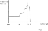
- Figure 3 illustrates how the resistance to close of the lid of a container according to the invention comprising an inner frame 100 as described above varies as a function of the angle between the lid back wall and the box back wall.
- the locking tabs 120, 122 frictionally engage the inner surface of the lid side walls and thus contribute to the force required for opening and closing the lid.
- the resistance to closing progressively increases as the lid approaches the closed position.
- the resistance to closing oscillates with a succession of local maxima and minima. Without wishing to be bound to theory, this is understood to be a consequence of the peaks 128 and troughs 130 of the undulated cut lines 112, 114.
Claims (15)
- Récipient pour articles de consommation, le récipient comprenant :une partie étui ;une partie de couvercle, où la partie de couvercle est mobile par rapport à la partie étui entre une position ouverte et une position fermée ; etun cadre intérieur (100) logé dans la partie étui,où le cadre intérieur (100) comprend :une paroi avant du cadre intérieur (102) ;les première et deuxième parois latérales du cadre intérieur (104, 106) chacune disposée le long d'une ligne de pliage de cadre intérieur (108, 110) de la paroi avant du cadre intérieur (102) ;une première ligne de coupe (112) et une deuxième ligne de coupe (114) dans les première et deuxième parois latérales du cadre intérieur (104, 106), respectivement, où chacune des première et deuxième lignes de coupe (112, 114) intersecte une ligne de pliage de cadre intérieur respective (108, 110) aux points d'intersection supérieurs et inférieurs (116, 118) ; les première et deuxième lignes de coupe (112, 114) définissant un premier et un deuxième languette de verrouillage (120, 122) ; chacun des premier et deuxième languette de verrouillage (120, 122) s'étendant à l'extérieur du cadre intérieur vers une paroi latérale respective du récipient et au-delà d'un bord formé par la paroi avant du cadre intérieur (102) avec une paroi latérale de cadre intérieur respective (104, 106), et interagissant avec la partie couvercle du récipient lorsque la partie de couvercle est déplacée entre la position ouverte et la position fermée ;caractérisé en ce que chacune des premières et deuxièmes lignes de coupe (112, 124) comprend une partie ondulée (124, 126) comprenant au moins deux pics (128) et un creux (130), une distance entre les pics adjacents (128) de la partie ondulée (124, 126) étant d'au moins environ 0,8 mm.
- Récipient selon la revendication 1, dans lequel la distance entre les pics adjacents (128) de la partie ondulée (124, 126) est inférieure à 40 mm environ.
- Récipient selon la revendication 1 ou 2, dans lequel chaque languette de verrouillage (120, 122) se rétrécit vers une extrémité supérieure de la ligne de coupe respective (112, 114), et la tangente à chacune des première et deuxième lignes de coupe (112, 114) aux points d'intersection supérieurs (116) forme, avec la ligne de pliage de cadre intérieur respective (108, 110), un angle d'au moins environ 5 degrés.
- Récipient selon la revendication 3, dans lequel la tangente à chacune des première et deuxième lignes de coupe (112, 114) aux points d'intersection supérieurs (116) forme, avec la ligne de pliage de paroi latérale de cadre intérieur respective (108, 110), un angle de moins d'environ 30 degrés.
- Récipient selon l'une quelconque des revendications précédentes, dans lequel chaque ligne de coupe (112, 114) comprend une partie supérieure inclinée (132, 134) s'étendant vers l'extérieur et vers le bas à partir du point d'intersection supérieur (116).
- Récipient selon la revendication 5, dans lequel la partie supérieure inclinée (132, 134) a une longueur d'au moins environ 0,5 mm.
- Récipient selon l'une quelconque des revendications précédentes, dans lequel chaque ligne de coupe (112, 114) comprend une partie de rampe inférieure (136, 138) s'étendant vers l'extérieur et vers le haut depuis le point d'intersection inférieur.
- Récipient selon la revendication 7, dans lequel la partie de rampe inférieure (136, 138) est définie par une ligne droite, un arc ou une combinaison d'une ligne droite et d'un arc.
- Récipient selon la revendication 7 ou 8, dans lequel la partie ondulée (124, 126) est comprise entre la partie supérieure inclinée (132, 134) et la partie inférieure de rampe (136, 138).
- Récipient selon l'une quelconque des revendications précédentes, dans lequel la distance entre les points d'intersection supérieur et inférieur (116, 118) telle que mesurée le long d'une ligne de pliage de paroi latérale de cadre intérieur respective (108, 110) est d'au moins environ 10 mm.
- Récipient selon l'une quelconque des revendications précédentes, dans lequel la distance entre les points d'intersection supérieur et inférieur (116, 118) telle que mesurée le long d'une ligne de pliage de paroi latérale de cadre intérieur respective (108, 110) est inférieure à environ 20 mm.
- Ébauche pour un cadre intérieur (100) adapté pour être logé dans une partie de boîte d'un récipient pour des articles de consommation, le récipient comprenant en outre une partie de couvercle, dans lequel la partie de couvercle est mobile autour de la ligne de charnière entre une position ouverte et une position fermée ; l'ébauche comprenant :un panneau frontal de l'ébauche pour former une paroi avant du cadre intérieur (102) et des premier et deuxième panneaux latéraux de l'ébauche pour former les parois latérales du cadre intérieur (104, 106), chacune des premier et deuxième panneaux latéraux du cadre intérieur disposés le long d'une ligne de pliage respective (108, 110) du panneau frontal de l'ébauche (102) ;une première ligne de coupe (112) et une deuxième ligne de coupe (114) dans les premier et deuxième panneaux latéraux du cadre intérieur, respectivement, où chacune des première et deuxième lignes de coupe intersecte une ligne de pliage respective (108, 110) aux points d'intersection supérieur et inférieur (116, 118) ; les première et deuxième lignes de coupe (112, 114) définissant les première et deuxième languettes de verrouillage (120, 122) ; chacun des première et deuxième languettes de verrouillage (120, 122) s'étendant à l'extérieur du cadre intérieur et au-delà d'un bord formé par le panneau de paroi avant du cadre intérieur (102) et un panneau latéral du cadre intérieur respectif (104, 106) lorsque les premier et deuxième panneaux latéraux du cadre intérieur sont pliés autour des lignes de pliage respectives (108, 110) ; les première et deuxième languettes de verrouillage (120, 122) étant adaptées pour interagir avec la partie couvercle du récipient lorsque le cadre intérieur (100) est logé dans le récipient assemblé et que la partie de couvercle est déplacée entre la position ouverte et la position fermée ;caractérisé en ce que les première et deuxième lignes de coupe (112, 114) comprennent une partie ondulée (124, 126) comprenant au moins deux pics (128) et un creux (130), une distance entre les pics adjacents (128) de la partie ondulée (124, 126) étant d'au moins environ 0,8 mm.
- Ébauche selon la revendication 12, dans laquelle la distance entre les pics adjacents (128) de la partie ondulée (124, 126) est inférieure à 40 mm environ.
- Ébauche selon la revendication 12 ou 13, dans laquelle chaque languette de verrouillage (120, 122) se rétrécit vers une extrémité supérieure de la ligne de coupe respective (112, 114), et la tangente à chacune des première et deuxième lignes de coupe (112, 114) aux points d'intersection supérieurs (116) forme, avec la ligne de pliage de cadre intérieur respective (108, 110), un angle d'au moins environ 5 degrés.
- Ébauche selon la revendication 14, dans laquelle la tangente à chacune des première et deuxième lignes de coupe (112, 114) aux points d'intersection supérieurs (116) forme, avec la ligne de pliage de paroi latérale de cadre intérieur respective (108, 110), un angle de moins d'environ 30 degrés.
Priority Applications (1)
| Application Number | Priority Date | Filing Date | Title |
|---|---|---|---|
| PL16766312T PL3350086T3 (pl) | 2015-09-18 | 2016-09-16 | Opakowanie na towary konsumpcyjne z płynnie zamykanym wieczkiem |
Applications Claiming Priority (2)
| Application Number | Priority Date | Filing Date | Title |
|---|---|---|---|
| EP15185956 | 2015-09-18 | ||
| PCT/EP2016/071963 WO2017046325A1 (fr) | 2015-09-18 | 2016-09-16 | Contenant pour articles de consommation doté d'une action de fermeture de couvercle sans à-coup |
Publications (2)
| Publication Number | Publication Date |
|---|---|
| EP3350086A1 EP3350086A1 (fr) | 2018-07-25 |
| EP3350086B1 true EP3350086B1 (fr) | 2019-07-17 |
Family
ID=54150345
Family Applications (1)
| Application Number | Title | Priority Date | Filing Date |
|---|---|---|---|
| EP16766312.9A Not-in-force EP3350086B1 (fr) | 2015-09-18 | 2016-09-16 | Récipient pour produits de consommation à action de fermeture de couvercle liss |
Country Status (10)
| Country | Link |
|---|---|
| US (1) | US20180257849A1 (fr) |
| EP (1) | EP3350086B1 (fr) |
| JP (1) | JP2018527258A (fr) |
| KR (1) | KR20180054579A (fr) |
| CN (1) | CN108025830A (fr) |
| ES (1) | ES2742521T3 (fr) |
| MX (1) | MX2018003034A (fr) |
| PL (1) | PL3350086T3 (fr) |
| RU (1) | RU2018114067A (fr) |
| WO (1) | WO2017046325A1 (fr) |
Families Citing this family (1)
| Publication number | Priority date | Publication date | Assignee | Title |
|---|---|---|---|---|
| KR20220039710A (ko) | 2019-07-23 | 2022-03-29 | 닛산 가가쿠 가부시키가이샤 | 감광성 수지 조성물 |
Family Cites Families (21)
| Publication number | Priority date | Publication date | Assignee | Title |
|---|---|---|---|---|
| US2848152A (en) * | 1956-10-31 | 1958-08-19 | Sr Clarence H Geiger | Paper container and blank for constructing same |
| US3708108A (en) * | 1971-09-22 | 1973-01-02 | Burt Co Inc F | Flip top carton |
| GB1431173A (en) * | 1972-06-30 | 1976-04-07 | Molins Ltd | Boxes or packets |
| US4392338A (en) * | 1976-03-15 | 1983-07-12 | Molins Limited | Packets and the manufacture thereof |
| US4216898A (en) * | 1976-08-06 | 1980-08-12 | Molins Limited | Cigarette packets |
| US5341925A (en) * | 1993-07-30 | 1994-08-30 | Philip Morris Incorporated | Cigarette hardpack having rounded corners and lid retaining flaps |
| GB9419304D0 (en) * | 1994-09-24 | 1994-11-09 | Imp Tobacco Co Ltd | Packs for smoking articles |
| US5964345A (en) * | 1994-11-07 | 1999-10-12 | G. D S.P.A. | Cigarette packet with a hinged lid |
| DE19648240B4 (de) * | 1996-11-21 | 2006-01-05 | Focke & Co.(Gmbh & Co. Kg) | Klappschachtel für Zigaretten und Zuschnitt zur Herstellung derselben |
| ITBO20050099A1 (it) * | 2005-02-24 | 2005-05-26 | Gd Spa | Incarto rigido per articoli da fumo con coperchio incernierato |
| GB0806700D0 (en) * | 2008-04-14 | 2008-05-14 | British American Tobacco Co | Package for smoking articles |
| US20100059395A1 (en) * | 2008-05-02 | 2010-03-11 | John England | Pack for Smoking Articles |
| IT1391000B1 (it) * | 2008-07-04 | 2011-10-27 | Marco Vecchi | Pacchetto e relativo fustellato |
| GB0822143D0 (en) * | 2008-12-04 | 2009-01-14 | British American Tobacco Co | Packet |
| CA2779032A1 (fr) * | 2009-11-04 | 2011-05-12 | Imperial Tobacco Canada Limited | Emballage a couvercle articule |
| CN103003173B (zh) * | 2010-07-19 | 2015-11-25 | 菲利普莫里斯生产公司 | 消费品容器 |
| GB201103091D0 (en) * | 2011-02-23 | 2011-04-06 | British American Tobacco Co | A package for smoking articles |
| GB2488595A (en) * | 2011-03-04 | 2012-09-05 | British American Tobacco Co | Cigarette Pack with Recess and Locking Element |
| GB201202142D0 (en) * | 2012-02-08 | 2012-03-21 | British American Tobacco Co | A pack |
| ITBO20120076A1 (it) * | 2012-02-20 | 2013-08-21 | Gd Spa | Pacchetto rigido di sigarette o simili. |
| WO2014068704A1 (fr) * | 2012-10-31 | 2014-05-08 | 日本たばこ産業株式会社 | Paquet doté d'un couvercle articulé |
-
2016
- 2016-09-16 PL PL16766312T patent/PL3350086T3/pl unknown
- 2016-09-16 RU RU2018114067A patent/RU2018114067A/ru not_active Application Discontinuation
- 2016-09-16 EP EP16766312.9A patent/EP3350086B1/fr not_active Not-in-force
- 2016-09-16 WO PCT/EP2016/071963 patent/WO2017046325A1/fr active Application Filing
- 2016-09-16 JP JP2018513598A patent/JP2018527258A/ja not_active Abandoned
- 2016-09-16 CN CN201680051438.XA patent/CN108025830A/zh active Pending
- 2016-09-16 US US15/760,407 patent/US20180257849A1/en not_active Abandoned
- 2016-09-16 KR KR1020187005366A patent/KR20180054579A/ko unknown
- 2016-09-16 ES ES16766312T patent/ES2742521T3/es active Active
- 2016-09-16 MX MX2018003034A patent/MX2018003034A/es unknown
Non-Patent Citations (1)
| Title |
|---|
| None * |
Also Published As
| Publication number | Publication date |
|---|---|
| JP2018527258A (ja) | 2018-09-20 |
| PL3350086T3 (pl) | 2020-03-31 |
| ES2742521T3 (es) | 2020-02-14 |
| WO2017046325A1 (fr) | 2017-03-23 |
| CN108025830A (zh) | 2018-05-11 |
| MX2018003034A (es) | 2018-05-02 |
| RU2018114067A3 (fr) | 2019-10-18 |
| EP3350086A1 (fr) | 2018-07-25 |
| RU2018114067A (ru) | 2019-10-18 |
| US20180257849A1 (en) | 2018-09-13 |
| KR20180054579A (ko) | 2018-05-24 |
Similar Documents
| Publication | Publication Date | Title |
|---|---|---|
| US8281922B2 (en) | Hinge lid container and blank | |
| EP2619112B1 (fr) | Contenant à couvercle articulé doté d'un signal de fermeture audible | |
| US8800761B2 (en) | Container for consumer goods | |
| WO2014206939A1 (fr) | Récipient à couvercle articulé avec bord supérieur incurvé | |
| EP2403778B1 (fr) | Récipient à couvercle articulé avec élément coulissant | |
| US20140339108A1 (en) | Container with hinged lid | |
| EP2594507A1 (fr) | Récipient avec couvercle formé d'une seule ébauche laminaire | |
| KR20050121720A (ko) | 미끄럼이동하는 뚜껑을 갖춘 포장상자 | |
| WO2015124643A1 (fr) | Contenant pour articles de consommation avec armature intérieure réglable | |
| EP3350086B1 (fr) | Récipient pour produits de consommation à action de fermeture de couvercle liss | |
| EP3240739B1 (fr) | Récipient pour produits de consommation doté d'un mécanisme d'ouverture et de fermeture | |
| WO2010003697A1 (fr) | Contenant à couvercle articulé doté de languettes de fermeture sur la paroi latérale intérieure | |
| EP3040292A1 (fr) | Récipient à couvercle articulé avec des lignes d'articulation convergentes | |
| EP3107832B1 (fr) | Conteneur pour articles de consommation avec agencement oblique | |
| US20190092560A1 (en) | Container with top curved bevelled edge | |
| EP2546158A1 (fr) | Récipient pour aliments de consommation formés d'une seule ébauche laminaire | |
| WO2013011012A1 (fr) | Contenant à étui et tiroir comportant un tiroir intérieur pivotant |
Legal Events
| Date | Code | Title | Description |
|---|---|---|---|
| STAA | Information on the status of an ep patent application or granted ep patent |
Free format text: STATUS: UNKNOWN |
|
| STAA | Information on the status of an ep patent application or granted ep patent |
Free format text: STATUS: THE INTERNATIONAL PUBLICATION HAS BEEN MADE |
|
| PUAI | Public reference made under article 153(3) epc to a published international application that has entered the european phase |
Free format text: ORIGINAL CODE: 0009012 |
|
| STAA | Information on the status of an ep patent application or granted ep patent |
Free format text: STATUS: REQUEST FOR EXAMINATION WAS MADE |
|
| 17P | Request for examination filed |
Effective date: 20171219 |
|
| AK | Designated contracting states |
Kind code of ref document: A1 Designated state(s): AL AT BE BG CH CY CZ DE DK EE ES FI FR GB GR HR HU IE IS IT LI LT LU LV MC MK MT NL NO PL PT RO RS SE SI SK SM TR |
|
| AX | Request for extension of the european patent |
Extension state: BA ME |
|
| DAV | Request for validation of the european patent (deleted) | ||
| DAX | Request for extension of the european patent (deleted) | ||
| GRAP | Despatch of communication of intention to grant a patent |
Free format text: ORIGINAL CODE: EPIDOSNIGR1 |
|
| STAA | Information on the status of an ep patent application or granted ep patent |
Free format text: STATUS: GRANT OF PATENT IS INTENDED |
|
| INTG | Intention to grant announced |
Effective date: 20190212 |
|
| GRAS | Grant fee paid |
Free format text: ORIGINAL CODE: EPIDOSNIGR3 |
|
| GRAA | (expected) grant |
Free format text: ORIGINAL CODE: 0009210 |
|
| STAA | Information on the status of an ep patent application or granted ep patent |
Free format text: STATUS: THE PATENT HAS BEEN GRANTED |
|
| AK | Designated contracting states |
Kind code of ref document: B1 Designated state(s): AL AT BE BG CH CY CZ DE DK EE ES FI FR GB GR HR HU IE IS IT LI LT LU LV MC MK MT NL NO PL PT RO RS SE SI SK SM TR |
|
| REG | Reference to a national code |
Ref country code: GB Ref legal event code: FG4D |
|
| REG | Reference to a national code |
Ref country code: CH Ref legal event code: EP |
|
| REG | Reference to a national code |
Ref country code: IE Ref legal event code: FG4D |
|
| REG | Reference to a national code |
Ref country code: DE Ref legal event code: R096 Ref document number: 602016017069 Country of ref document: DE |
|
| REG | Reference to a national code |
Ref country code: AT Ref legal event code: REF Ref document number: 1155654 Country of ref document: AT Kind code of ref document: T Effective date: 20190815 |
|
| REG | Reference to a national code |
Ref country code: NL Ref legal event code: FP Ref country code: RO Ref legal event code: EPE |
|
| REG | Reference to a national code |
Ref country code: CH Ref legal event code: NV Representative=s name: VENI GMBH, CH |
|
| PGFP | Annual fee paid to national office [announced via postgrant information from national office to epo] |
Ref country code: TR Payment date: 20190919 Year of fee payment: 4 Ref country code: NL Payment date: 20190918 Year of fee payment: 4 Ref country code: IT Payment date: 20190930 Year of fee payment: 4 Ref country code: FR Payment date: 20190927 Year of fee payment: 4 Ref country code: DE Payment date: 20190918 Year of fee payment: 4 Ref country code: RO Payment date: 20190824 Year of fee payment: 4 Ref country code: CZ Payment date: 20190827 Year of fee payment: 4 |
|
| REG | Reference to a national code |
Ref country code: LT Ref legal event code: MG4D |
|
| REG | Reference to a national code |
Ref country code: AT Ref legal event code: MK05 Ref document number: 1155654 Country of ref document: AT Kind code of ref document: T Effective date: 20190717 |
|
| REG | Reference to a national code |
Ref country code: GR Ref legal event code: EP Ref document number: 20190403092 Country of ref document: GR Effective date: 20200122 |
|
| PG25 | Lapsed in a contracting state [announced via postgrant information from national office to epo] |
Ref country code: PT Free format text: LAPSE BECAUSE OF FAILURE TO SUBMIT A TRANSLATION OF THE DESCRIPTION OR TO PAY THE FEE WITHIN THE PRESCRIBED TIME-LIMIT Effective date: 20191118 Ref country code: AT Free format text: LAPSE BECAUSE OF FAILURE TO SUBMIT A TRANSLATION OF THE DESCRIPTION OR TO PAY THE FEE WITHIN THE PRESCRIBED TIME-LIMIT Effective date: 20190717 Ref country code: HR Free format text: LAPSE BECAUSE OF FAILURE TO SUBMIT A TRANSLATION OF THE DESCRIPTION OR TO PAY THE FEE WITHIN THE PRESCRIBED TIME-LIMIT Effective date: 20190717 Ref country code: BG Free format text: LAPSE BECAUSE OF FAILURE TO SUBMIT A TRANSLATION OF THE DESCRIPTION OR TO PAY THE FEE WITHIN THE PRESCRIBED TIME-LIMIT Effective date: 20191017 Ref country code: LT Free format text: LAPSE BECAUSE OF FAILURE TO SUBMIT A TRANSLATION OF THE DESCRIPTION OR TO PAY THE FEE WITHIN THE PRESCRIBED TIME-LIMIT Effective date: 20190717 Ref country code: SE Free format text: LAPSE BECAUSE OF FAILURE TO SUBMIT A TRANSLATION OF THE DESCRIPTION OR TO PAY THE FEE WITHIN THE PRESCRIBED TIME-LIMIT Effective date: 20190717 Ref country code: NO Free format text: LAPSE BECAUSE OF FAILURE TO SUBMIT A TRANSLATION OF THE DESCRIPTION OR TO PAY THE FEE WITHIN THE PRESCRIBED TIME-LIMIT Effective date: 20191017 Ref country code: FI Free format text: LAPSE BECAUSE OF FAILURE TO SUBMIT A TRANSLATION OF THE DESCRIPTION OR TO PAY THE FEE WITHIN THE PRESCRIBED TIME-LIMIT Effective date: 20190717 |
|
| PGFP | Annual fee paid to national office [announced via postgrant information from national office to epo] |
Ref country code: CH Payment date: 20190919 Year of fee payment: 4 |
|
| REG | Reference to a national code |
Ref country code: ES Ref legal event code: FG2A Ref document number: 2742521 Country of ref document: ES Kind code of ref document: T3 Effective date: 20200214 |
|
| PG25 | Lapsed in a contracting state [announced via postgrant information from national office to epo] |
Ref country code: IS Free format text: LAPSE BECAUSE OF FAILURE TO SUBMIT A TRANSLATION OF THE DESCRIPTION OR TO PAY THE FEE WITHIN THE PRESCRIBED TIME-LIMIT Effective date: 20191117 Ref country code: RS Free format text: LAPSE BECAUSE OF FAILURE TO SUBMIT A TRANSLATION OF THE DESCRIPTION OR TO PAY THE FEE WITHIN THE PRESCRIBED TIME-LIMIT Effective date: 20190717 Ref country code: AL Free format text: LAPSE BECAUSE OF FAILURE TO SUBMIT A TRANSLATION OF THE DESCRIPTION OR TO PAY THE FEE WITHIN THE PRESCRIBED TIME-LIMIT Effective date: 20190717 Ref country code: LV Free format text: LAPSE BECAUSE OF FAILURE TO SUBMIT A TRANSLATION OF THE DESCRIPTION OR TO PAY THE FEE WITHIN THE PRESCRIBED TIME-LIMIT Effective date: 20190717 |
|
| PGFP | Annual fee paid to national office [announced via postgrant information from national office to epo] |
Ref country code: GR Payment date: 20191014 Year of fee payment: 4 |
|
| PG25 | Lapsed in a contracting state [announced via postgrant information from national office to epo] |
Ref country code: DK Free format text: LAPSE BECAUSE OF FAILURE TO SUBMIT A TRANSLATION OF THE DESCRIPTION OR TO PAY THE FEE WITHIN THE PRESCRIBED TIME-LIMIT Effective date: 20190717 Ref country code: EE Free format text: LAPSE BECAUSE OF FAILURE TO SUBMIT A TRANSLATION OF THE DESCRIPTION OR TO PAY THE FEE WITHIN THE PRESCRIBED TIME-LIMIT Effective date: 20190717 |
|
| PGFP | Annual fee paid to national office [announced via postgrant information from national office to epo] |
Ref country code: PL Payment date: 20200213 Year of fee payment: 4 |
|
| PG25 | Lapsed in a contracting state [announced via postgrant information from national office to epo] |
Ref country code: SM Free format text: LAPSE BECAUSE OF FAILURE TO SUBMIT A TRANSLATION OF THE DESCRIPTION OR TO PAY THE FEE WITHIN THE PRESCRIBED TIME-LIMIT Effective date: 20190717 Ref country code: SK Free format text: LAPSE BECAUSE OF FAILURE TO SUBMIT A TRANSLATION OF THE DESCRIPTION OR TO PAY THE FEE WITHIN THE PRESCRIBED TIME-LIMIT Effective date: 20190717 Ref country code: MC Free format text: LAPSE BECAUSE OF FAILURE TO SUBMIT A TRANSLATION OF THE DESCRIPTION OR TO PAY THE FEE WITHIN THE PRESCRIBED TIME-LIMIT Effective date: 20190717 Ref country code: IS Free format text: LAPSE BECAUSE OF FAILURE TO SUBMIT A TRANSLATION OF THE DESCRIPTION OR TO PAY THE FEE WITHIN THE PRESCRIBED TIME-LIMIT Effective date: 20200224 |
|
| REG | Reference to a national code |
Ref country code: DE Ref legal event code: R097 Ref document number: 602016017069 Country of ref document: DE |
|
| PLBE | No opposition filed within time limit |
Free format text: ORIGINAL CODE: 0009261 |
|
| STAA | Information on the status of an ep patent application or granted ep patent |
Free format text: STATUS: NO OPPOSITION FILED WITHIN TIME LIMIT |
|
| PG2D | Information on lapse in contracting state deleted |
Ref country code: IS |
|
| PG25 | Lapsed in a contracting state [announced via postgrant information from national office to epo] |
Ref country code: IE Free format text: LAPSE BECAUSE OF NON-PAYMENT OF DUE FEES Effective date: 20190916 Ref country code: LU Free format text: LAPSE BECAUSE OF NON-PAYMENT OF DUE FEES Effective date: 20190916 |
|
| 26N | No opposition filed |
Effective date: 20200603 |
|
| REG | Reference to a national code |
Ref country code: BE Ref legal event code: MM Effective date: 20190930 |
|
| PG25 | Lapsed in a contracting state [announced via postgrant information from national office to epo] |
Ref country code: SI Free format text: LAPSE BECAUSE OF FAILURE TO SUBMIT A TRANSLATION OF THE DESCRIPTION OR TO PAY THE FEE WITHIN THE PRESCRIBED TIME-LIMIT Effective date: 20190717 Ref country code: BE Free format text: LAPSE BECAUSE OF NON-PAYMENT OF DUE FEES Effective date: 20190930 |
|
| REG | Reference to a national code |
Ref country code: ES Ref legal event code: FD2A Effective date: 20210127 |
|
| REG | Reference to a national code |
Ref country code: DE Ref legal event code: R119 Ref document number: 602016017069 Country of ref document: DE |
|
| PG25 | Lapsed in a contracting state [announced via postgrant information from national office to epo] |
Ref country code: RO Free format text: LAPSE BECAUSE OF NON-PAYMENT OF DUE FEES Effective date: 20200916 Ref country code: CZ Free format text: LAPSE BECAUSE OF NON-PAYMENT OF DUE FEES Effective date: 20200916 |
|
| REG | Reference to a national code |
Ref country code: CH Ref legal event code: PL |
|
| REG | Reference to a national code |
Ref country code: NL Ref legal event code: MM Effective date: 20201001 |
|
| GBPC | Gb: european patent ceased through non-payment of renewal fee |
Effective date: 20200916 |
|
| PG25 | Lapsed in a contracting state [announced via postgrant information from national office to epo] |
Ref country code: CY Free format text: LAPSE BECAUSE OF FAILURE TO SUBMIT A TRANSLATION OF THE DESCRIPTION OR TO PAY THE FEE WITHIN THE PRESCRIBED TIME-LIMIT Effective date: 20190717 Ref country code: ES Free format text: LAPSE BECAUSE OF NON-PAYMENT OF DUE FEES Effective date: 20190917 |
|
| PG25 | Lapsed in a contracting state [announced via postgrant information from national office to epo] |
Ref country code: NL Free format text: LAPSE BECAUSE OF NON-PAYMENT OF DUE FEES Effective date: 20201001 |
|
| PG25 | Lapsed in a contracting state [announced via postgrant information from national office to epo] |
Ref country code: DE Free format text: LAPSE BECAUSE OF NON-PAYMENT OF DUE FEES Effective date: 20210401 Ref country code: MT Free format text: LAPSE BECAUSE OF FAILURE TO SUBMIT A TRANSLATION OF THE DESCRIPTION OR TO PAY THE FEE WITHIN THE PRESCRIBED TIME-LIMIT Effective date: 20190717 Ref country code: HU Free format text: LAPSE BECAUSE OF FAILURE TO SUBMIT A TRANSLATION OF THE DESCRIPTION OR TO PAY THE FEE WITHIN THE PRESCRIBED TIME-LIMIT; INVALID AB INITIO Effective date: 20160916 Ref country code: FR Free format text: LAPSE BECAUSE OF NON-PAYMENT OF DUE FEES Effective date: 20200930 Ref country code: GR Free format text: LAPSE BECAUSE OF NON-PAYMENT OF DUE FEES Effective date: 20210406 |
|
| PG25 | Lapsed in a contracting state [announced via postgrant information from national office to epo] |
Ref country code: GB Free format text: LAPSE BECAUSE OF NON-PAYMENT OF DUE FEES Effective date: 20200916 Ref country code: LI Free format text: LAPSE BECAUSE OF NON-PAYMENT OF DUE FEES Effective date: 20200930 Ref country code: CH Free format text: LAPSE BECAUSE OF NON-PAYMENT OF DUE FEES Effective date: 20200930 |
|
| PG25 | Lapsed in a contracting state [announced via postgrant information from national office to epo] |
Ref country code: IT Free format text: LAPSE BECAUSE OF NON-PAYMENT OF DUE FEES Effective date: 20200916 |
|
| PG25 | Lapsed in a contracting state [announced via postgrant information from national office to epo] |
Ref country code: TR Free format text: LAPSE BECAUSE OF NON-PAYMENT OF DUE FEES Effective date: 20200916 Ref country code: MK Free format text: LAPSE BECAUSE OF FAILURE TO SUBMIT A TRANSLATION OF THE DESCRIPTION OR TO PAY THE FEE WITHIN THE PRESCRIBED TIME-LIMIT Effective date: 20190717 |
|
| PG25 | Lapsed in a contracting state [announced via postgrant information from national office to epo] |
Ref country code: PL Free format text: LAPSE BECAUSE OF NON-PAYMENT OF DUE FEES Effective date: 20200916 |