EP3350019B1 - Système d'éclairage pour véhicules automobiles - Google Patents
Système d'éclairage pour véhicules automobiles Download PDFInfo
- Publication number
- EP3350019B1 EP3350019B1 EP16770717.3A EP16770717A EP3350019B1 EP 3350019 B1 EP3350019 B1 EP 3350019B1 EP 16770717 A EP16770717 A EP 16770717A EP 3350019 B1 EP3350019 B1 EP 3350019B1
- Authority
- EP
- European Patent Office
- Prior art keywords
- zone
- group
- optical axis
- projection
- illumination
- Prior art date
- Legal status (The legal status is an assumption and is not a legal conclusion. Google has not performed a legal analysis and makes no representation as to the accuracy of the status listed.)
- Active
Links
Images


Classifications
-
- F—MECHANICAL ENGINEERING; LIGHTING; HEATING; WEAPONS; BLASTING
- F21—LIGHTING
- F21S—NON-PORTABLE LIGHTING DEVICES; SYSTEMS THEREOF; VEHICLE LIGHTING DEVICES SPECIALLY ADAPTED FOR VEHICLE EXTERIORS
- F21S41/00—Illuminating devices specially adapted for vehicle exteriors, e.g. headlamps
- F21S41/60—Illuminating devices specially adapted for vehicle exteriors, e.g. headlamps characterised by a variable light distribution
- F21S41/67—Illuminating devices specially adapted for vehicle exteriors, e.g. headlamps characterised by a variable light distribution by acting on reflectors
- F21S41/675—Illuminating devices specially adapted for vehicle exteriors, e.g. headlamps characterised by a variable light distribution by acting on reflectors by moving reflectors
-
- B—PERFORMING OPERATIONS; TRANSPORTING
- B60—VEHICLES IN GENERAL
- B60Q—ARRANGEMENT OF SIGNALLING OR LIGHTING DEVICES, THE MOUNTING OR SUPPORTING THEREOF OR CIRCUITS THEREFOR, FOR VEHICLES IN GENERAL
- B60Q1/00—Arrangement of optical signalling or lighting devices, the mounting or supporting thereof or circuits therefor
- B60Q1/02—Arrangement of optical signalling or lighting devices, the mounting or supporting thereof or circuits therefor the devices being primarily intended to illuminate the way ahead or to illuminate other areas of way or environments
- B60Q1/04—Arrangement of optical signalling or lighting devices, the mounting or supporting thereof or circuits therefor the devices being primarily intended to illuminate the way ahead or to illuminate other areas of way or environments the devices being headlights
- B60Q1/06—Arrangement of optical signalling or lighting devices, the mounting or supporting thereof or circuits therefor the devices being primarily intended to illuminate the way ahead or to illuminate other areas of way or environments the devices being headlights adjustable, e.g. remotely-controlled from inside vehicle
- B60Q1/08—Arrangement of optical signalling or lighting devices, the mounting or supporting thereof or circuits therefor the devices being primarily intended to illuminate the way ahead or to illuminate other areas of way or environments the devices being headlights adjustable, e.g. remotely-controlled from inside vehicle automatically
- B60Q1/085—Arrangement of optical signalling or lighting devices, the mounting or supporting thereof or circuits therefor the devices being primarily intended to illuminate the way ahead or to illuminate other areas of way or environments the devices being headlights adjustable, e.g. remotely-controlled from inside vehicle automatically due to special conditions, e.g. adverse weather, type of road, badly illuminated road signs or potential dangers
-
- F—MECHANICAL ENGINEERING; LIGHTING; HEATING; WEAPONS; BLASTING
- F21—LIGHTING
- F21S—NON-PORTABLE LIGHTING DEVICES; SYSTEMS THEREOF; VEHICLE LIGHTING DEVICES SPECIALLY ADAPTED FOR VEHICLE EXTERIORS
- F21S41/00—Illuminating devices specially adapted for vehicle exteriors, e.g. headlamps
- F21S41/10—Illuminating devices specially adapted for vehicle exteriors, e.g. headlamps characterised by the light source
- F21S41/14—Illuminating devices specially adapted for vehicle exteriors, e.g. headlamps characterised by the light source characterised by the type of light source
- F21S41/141—Light emitting diodes [LED]
-
- F—MECHANICAL ENGINEERING; LIGHTING; HEATING; WEAPONS; BLASTING
- F21—LIGHTING
- F21S—NON-PORTABLE LIGHTING DEVICES; SYSTEMS THEREOF; VEHICLE LIGHTING DEVICES SPECIALLY ADAPTED FOR VEHICLE EXTERIORS
- F21S41/00—Illuminating devices specially adapted for vehicle exteriors, e.g. headlamps
- F21S41/30—Illuminating devices specially adapted for vehicle exteriors, e.g. headlamps characterised by reflectors
- F21S41/32—Optical layout thereof
- F21S41/321—Optical layout thereof the reflector being a surface of revolution or a planar surface, e.g. truncated
-
- F—MECHANICAL ENGINEERING; LIGHTING; HEATING; WEAPONS; BLASTING
- F21—LIGHTING
- F21S—NON-PORTABLE LIGHTING DEVICES; SYSTEMS THEREOF; VEHICLE LIGHTING DEVICES SPECIALLY ADAPTED FOR VEHICLE EXTERIORS
- F21S41/00—Illuminating devices specially adapted for vehicle exteriors, e.g. headlamps
- F21S41/30—Illuminating devices specially adapted for vehicle exteriors, e.g. headlamps characterised by reflectors
- F21S41/32—Optical layout thereof
- F21S41/36—Combinations of two or more separate reflectors
- F21S41/365—Combinations of two or more separate reflectors successively reflecting the light
-
- F—MECHANICAL ENGINEERING; LIGHTING; HEATING; WEAPONS; BLASTING
- F21—LIGHTING
- F21S—NON-PORTABLE LIGHTING DEVICES; SYSTEMS THEREOF; VEHICLE LIGHTING DEVICES SPECIALLY ADAPTED FOR VEHICLE EXTERIORS
- F21S41/00—Illuminating devices specially adapted for vehicle exteriors, e.g. headlamps
- F21S41/60—Illuminating devices specially adapted for vehicle exteriors, e.g. headlamps characterised by a variable light distribution
- F21S41/65—Illuminating devices specially adapted for vehicle exteriors, e.g. headlamps characterised by a variable light distribution by acting on light sources
- F21S41/663—Illuminating devices specially adapted for vehicle exteriors, e.g. headlamps characterised by a variable light distribution by acting on light sources by switching light sources
-
- B—PERFORMING OPERATIONS; TRANSPORTING
- B60—VEHICLES IN GENERAL
- B60Q—ARRANGEMENT OF SIGNALLING OR LIGHTING DEVICES, THE MOUNTING OR SUPPORTING THEREOF OR CIRCUITS THEREFOR, FOR VEHICLES IN GENERAL
- B60Q2300/00—Indexing codes for automatically adjustable headlamps or automatically dimmable headlamps
- B60Q2300/30—Indexing codes relating to the vehicle environment
- B60Q2300/31—Atmospheric conditions
- B60Q2300/312—Adverse weather
-
- B—PERFORMING OPERATIONS; TRANSPORTING
- B60—VEHICLES IN GENERAL
- B60Q—ARRANGEMENT OF SIGNALLING OR LIGHTING DEVICES, THE MOUNTING OR SUPPORTING THEREOF OR CIRCUITS THEREFOR, FOR VEHICLES IN GENERAL
- B60Q2400/00—Special features or arrangements of exterior signal lamps for vehicles
- B60Q2400/50—Projected symbol or information, e.g. onto the road or car body
-
- F—MECHANICAL ENGINEERING; LIGHTING; HEATING; WEAPONS; BLASTING
- F21—LIGHTING
- F21W—INDEXING SCHEME ASSOCIATED WITH SUBCLASSES F21K, F21L, F21S and F21V, RELATING TO USES OR APPLICATIONS OF LIGHTING DEVICES OR SYSTEMS
- F21W2102/00—Exterior vehicle lighting devices for illuminating purposes
- F21W2102/10—Arrangement or contour of the emitted light
- F21W2102/17—Arrangement or contour of the emitted light for regions other than high beam or low beam
- F21W2102/19—Arrangement or contour of the emitted light for regions other than high beam or low beam for curves
-
- F—MECHANICAL ENGINEERING; LIGHTING; HEATING; WEAPONS; BLASTING
- F21—LIGHTING
- F21W—INDEXING SCHEME ASSOCIATED WITH SUBCLASSES F21K, F21L, F21S and F21V, RELATING TO USES OR APPLICATIONS OF LIGHTING DEVICES OR SYSTEMS
- F21W2102/00—Exterior vehicle lighting devices for illuminating purposes
- F21W2102/20—Illuminance distribution within the emitted light
-
- F—MECHANICAL ENGINEERING; LIGHTING; HEATING; WEAPONS; BLASTING
- F21—LIGHTING
- F21Y—INDEXING SCHEME ASSOCIATED WITH SUBCLASSES F21K, F21L, F21S and F21V, RELATING TO THE FORM OR THE KIND OF THE LIGHT SOURCES OR OF THE COLOUR OF THE LIGHT EMITTED
- F21Y2115/00—Light-generating elements of semiconductor light sources
- F21Y2115/10—Light-emitting diodes [LED]
Definitions
- the present invention relates in particular to a lighting system.
- a preferred application concerns the automotive industry, for vehicle equipment, in particular for the production of devices capable of emitting light beams, also called lighting functions, generally meeting regulations.
- the invention can allow the production of a dipped beam type alone or in combination with a signaling and/or lighting function, of much lower intensity.
- the document US 2007/103923 A1 describes a lighting device capable of generating a dipped beam and comprising a plurality of modules generating sub-beams in order to adapt the lighting to the conditions in which the vehicle is located.
- the dipped beam is fundamental insofar as its good definition determines both the quality of the lighting and the absence, or reduction, of the inconvenience caused by the luminous flux produced for surrounding vehicles.
- dipped headlights are essentially defined with this in mind, with, in particular, the use of sometimes complex cut-offs at the top of the beam, so as to precisely limit or avoid illumination above the horizon line, and to best design a light projection zone to be prohibited because it is likely to inconvenience the driver of a vehicle passing by.
- the document JP 2014 189198 A describes a lighting system for a motor vehicle comprising a device for projecting a dipped beam.
- This device for projecting the dipped beam is designed such that the dipped beam comprises a dark area.
- the disclosed lighting system further comprises a projection device additional configured to project a pixelated beam into said dark area.
- the invention falls within this framework.
- It relates in particular to a lighting system for a motor vehicle according to claim 1, said system comprising a device for projecting a dipped beam in a projection zone.
- this system is such that the projection device is configured so that the dipped beam includes a zone of lesser illumination located inside the projection zone.
- the dipped beam has a light intensity modulated according to the projection location in the overall projection zone. This is advantageous in certain circumstances.
- the zone of lesser illumination having a less reflective effect for the driver.
- Another situation relates to the concomitant projection of an additional beam.
- the zone of lesser illumination can provide a space suitable for the projection of another beam.
- This beam can in particular allow signaling, being for example provided with a pictogram-type pattern.
- the invention offers a less energy-consuming and more flexible solution.
- the area of lower illumination of the dipped beam can be the location of an additional projection of low intensity, in particular less than that of the dipped beam.
- This characteristic also offers a range of technologies that can be used for the projection of the additional beam.
- These can be beam projection techniques in the form of pixelated rays. These techniques, which are not always powerful in terms of luminous flux, offer great flexibility in the choice of beam shapes. They can be used here, thanks to the area of lower illumination of the invention.
- the zone of lesser illumination comprises an upper limit angularly offset relative to an upper limit of the dipped beam by an angle value of at least 5°, preferably at least 6°, by relative to the point of emission of the dipped beam, in a vertical and longitudinal plane.
- the system comprises a device for projecting an additional beam formed of pixelated rays and configured to illuminate an area covering at least in part the area of lesser illumination.
- This technology offers high resolution and makes it possible to produce different shapes of additional beam.
- the area of lesser illumination preferably but not limited to an upper edge inclined by at least 5°, preferably 6°, relative to a horizontal plane.
- the invention allows an additional projection, inside the space occupied by the dipped beam. Since a zone of lower intensity is present, this additional beam can be less illuminating than the dipped beam as projected outside the zone of lower illumination.
- the dipped beam projection device comprises at least a plurality of modules each capable of producing a sub-beam participating in the dipped beam, the dipped beam projection device being configured such that the relative position of at least two sub-beams can be modified between at least one position in which the zone of lesser illumination is present and at least one other position in which the zone of lesser illumination is absent.
- the system of the invention can be placed in at least two different operating configurations.
- the first can represent the traditional dipped beam position, without a zone of lesser illumination.
- the second corresponds to the presence of a zone of lesser illumination.
- the system can evolve between two operating modes.
- the invention also relates to a vehicle equipped with at least one system as introduced above.
- the vehicle may comprise two systems, each on a different side of the vehicle's front end.
- the system can be integrated into a headlight projector block.
- verticality In the features set out below, the terms relating to verticality, horizontality and transversality, or their equivalents, are understood in relation to the position in which the lighting system is intended to be mounted in a vehicle.
- the terms “vertical” and “horizontal” are used in the present description to designate directions, following an orientation perpendicular to the plane of the horizon for the term “vertical”, and following an orientation parallel to the plane of the horizon for the term “horizontal”. They are to be considered in the operating conditions of the device in a vehicle.
- the use of these words does not mean that slight variations around the vertical and horizontal directions are excluded from the invention. For example, an inclination relative to these directions of the order of + or - 10° is here considered as a minor variation around the two preferred directions.
- bottom or lower part generally means a part of an element of the invention located, along a vertical plane, below the optical axis.
- top or upper part means a part of an element of the invention located, along a vertical plane, above the optical axis.
- parallel or the notion of coincident axes or lines is understood here in particular with manufacturing or assembly tolerances, substantially parallel directions or substantially coincident axes fall within this scope.
- crossing beam means a beam used when there are passing and/or following vehicles and/or other elements (individuals, obstacles, etc.) on or near the roadway.
- This beam has a downward average direction. It may optionally be characterized by an absence of light above a plane inclined at 1% downwards on the side of traffic in the other direction, and another plane inclined at 15 degrees relative to the previous one on the side of traffic in the same direction, these two planes defining a cut-off in accordance with European regulations. This upper cut-off The aim of the downward beam is to avoid dazzling other road users present in the road scene in front of the vehicle or on the verges of the road.
- the dipped beam formerly derived from a simple headlight, has undergone developments, the dipped beam function being able to be coupled with other lighting characteristics.
- New functions have recently been developed, designated as advanced functions and grouped under the name AFS (abbreviation for "Advanced Frontlighting System” in English), which notably offer other types of beams.
- AFS Advanced Frontlighting System
- cornering lighting functions are used when driving on a curve, and they are performed by means of projectors that emit a light beam whose horizontal orientation varies when the vehicle moves on a curved trajectory, so as to correctly illuminate the portions of road that are intended to be approached by the vehicle and which are not in the axis of the vehicle, but in the direction that it is about to take, resulting from the angle imparted to the steered wheels of the vehicle by its driver.
- Another function is called Town Light in English, for city lighting. This function ensures the widening of a dipped beam type beam while slightly reducing its range.
- the function called Motorway Light in English, for motorway lighting performs the motorway function.
- This function ensures an increase in the range of a dipped beam by concentrating the luminous flux of the dipped beam at the optical axis of the headlight device considered.
- Overhead Light in English, for gantry light.
- This function provides a modification of a typical dipped beam in such a way that signal gantries located above the road are adequately illuminated by means of the dipped beam.
- Another variant of dipped beam is the so-called AWL function (Adverse Weather Light). This function provides a modification of a dipped beam in such a way that the driver of an oncoming vehicle is not dazzled by the reflection of the headlights on the wet road.
- the vehicle attitude can be subject to more or less variable variations. significant, due for example to its state of charge, its acceleration or its deceleration, which cause a variation in the inclination of the upper cut-off of the beam, resulting either in dazzling other drivers if the cut-off is raised, or in insufficiently illuminating the road if the cut-off is lowered. It is then known to use a range corrector, with manual or automatic control, to correct the orientation of the dipped headlights.
- the dipped beam referred to by the invention comprises the dipped beam in accordance with the regulations and its developments including those described above.
- the dipped beam can be understood as any beam descending and/or illuminating the roadway without significantly exceeding the horizon line.
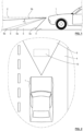
- the dipped beam 3 comprises an outer envelope with a lower limit 3a defining a limit of the envelope of the beam closest to the vehicle and corresponding to the greatest inclination relative to the horizontal plane 2 and an upper limit 3b corresponding to an upper limit of the envelope of the beam 3, the least inclined relative to the horizontal plane 2.
- one aspect of the invention is to propose a specific or evolving definition of the dipped beam 3.
- the figure 1 also schematizes the presence of a zone 5 of lesser illumination.
- zone 5 is delimited by a lower limit 5a and an upper limit 5b represented in dotted lines and defining, in a longitudinal and vertical plane perpendicular to the horizontal plane 2, the maximum and minimum inclinations respectively of the envelope of zone 5.
- the average luminous illuminance in the lesser illumination zone 5 is at least 70%, preferably at least 80%, more preferably at least 90%, preferably at least 97%, most preferably at least 99%, lower than the average luminous illuminance in the remainder of the projection zone of the dipped beam 3. In other words, it is sought to have virtually no light in this lesser illumination zone.
- Average luminous intensity values of less than 400 candelas, preferably less than 100 candelas, advantageously less than 50 candelas, more preferably less than 30 candelas will thus be noted in this lesser illumination zone while in the remainder of the beam, and in particular in the immediate vicinity of this zone, the values will be greater than at least 2000 or even 3000 candelas.
- this zone of lesser illumination 5 can vary inside the dipped beam 3, and as an example which will be repeated below, we could have a lower limit 5a of the zone 5 merged with the lower limit 3a of the dipped beam 3. It is particularly interesting, in particular in the use of this zone of lesser illumination for the projection of an additional beam 12 which we wish to make visible to the driver, that the zone of lesser illumination is arranged inside the dipped beam at a sufficient distance from the upper limit 3b of the dipped beam 3 to be bordered in its upper part by a zone of strong illumination.
- the zone of lesser illumination 5 comprises an upper limit 5b angularly offset relative to the upper limit 3b of the dipped beam 3, by an angle ⁇ (visible on the figure 1 ) relative to the emission point of the dipped beam in the longitudinal and vertical plane illustrated in the figure 1 , the angle ⁇ having a value of at least 5°.
- FIG 2 is a top view of a motor vehicle 1 and of an area located at the front of this vehicle.
- the projection of an additional beam 12 inside the dipped beam 3 is shown in dotted lines, the additional beam 12 being able to be configured so as to cover all or part of the area 5 previously presented.
- An advantage of the invention is to ensure that the additional beam 12 takes advantage of the characteristics of the zone 5 to produce specific lighting or signaling inside the dipped beam 3.
- the formation of the zone 5 is reversible in the sense that the definition of the dipped beam can be modified to eliminate this zone, or even reduce it, move it, enlarge it or modify its shape. Examples of embodiments of this beam modification are given later in the description.
- the zone 5 is of lesser illumination relative to the rest of the dipped beam 3, that is to say that it is presented in a relatively shaded form within the projection zone of the dipped beam 3.
- the additional beam 12 can carry out a projection at least at the level of this zone 5 so as, for example, to produce a complementary part of the dipped beam 3 relative to a part projected by a base projector of the dipped beam 3 or even to carry out a projection parallel to the dipped beam, for example to produce signaling as will be described in detail later.
- FIG 3 is another illustration of the insertion, in a dipped beam which may be traditional, of an additional beam 12.
- the horizontal plane 2 is represented in the form of a horizon line on a vertical plane containing a vertical axis 7 passing through the optical axis passing through the point A of the lighting system.
- the illuminated zone 6 of the dipped beam 3 may typically have an upper edge substantially at the level of the horizontal plane 2 of the horizon line and provided with a first portion corresponding to a high cut-off 6a slightly above the horizon, a second portion called a low cut-off 6c slightly below the horizon line, these two portions being joined by an intermediate portion corresponding to a bend 6b, here in the form of a bent portion, in particular linear, joining the portions 6a and 6c.
- the bend 6b passes through the optical axis illustrated by the point A.
- the illuminated zone 6 of the dipped beam 3 can generally have an envelope substantially in a convex curvilinear portion, for example in an arc of a circle or in a pseudo-elliptical portion. It is understood that this configuration generally makes it possible to illuminate an area at the front of the motor vehicle 1 which is located relatively close to the vehicle and which avoids an upward projection likely to dazzle vehicles crossed or followed by the vehicle equipped with the system of the invention.
- the present invention may allow additional functionality such as defining a specific area within the illuminated area 6 previously described, for example for the projection of an additional beam 12 schematized by the frame-shaped dotted lines in figure 3 only for the sake of explanation.
- the shape of the envelope of the additional beam 12 is in fact not limited.
- a projection device 8 which may or may not be a single-unit device and which comprises one or more optical modules 9, 10, 11 here represented in the same assembly, each nevertheless having an individual output optical element.
- the present invention may use, for all or part of the dipped beam projection device, in particular at the level of the modules 9, 10, 11, a light source for example of the light-emitting diode type also commonly called LED.
- this LED may be provided with at least one chip capable of emitting light of an intensity advantageously adjustable according to the lighting and/or signaling function to be performed.
- the term light source here means a set of at least one elementary source such as an LED capable of producing a flux leading to generating at the output of the device of the invention at least one output flux fulfilling at least one desired function.
- the source is generally associated with a support, connection means as well as heat dissipation means.
- the source is configured to emit in a mean emission direction which is perpendicular to the plane of the LED chip if this source technique is used.
- the modules may comprise an output diopter through which the beam is emitted, for example in the form of an external lens surface.
- Other types of sources are also conceivable in the invention, such as one or more laser sources, in particular for pixelated ray devices such as those with micro-mirror matrices described below.
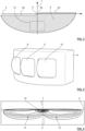
- a projection device 8 as shown in figure 4 and having three modules 9, 10, 11 allows for example the formation of a beam of which an isolux curve is represented in figure 5 .
- a first sub-beam 13 located on the right side of the isolux curve and for example in the form of closed oval and elongated curves in parallel lines substantially in a portion of the space located on one side of the vertical axis 7.
- This first sub-beam 13 can correspond to the result of the projection from the first optical module 9.
- a second sub-beam 14 is projected and is located in the case of the figure 5 on the other side of the vertical axis 7 relative to the first sub-beam 13.
- This second sub-beam 14 may correspond to the result of the projection from the second optical module 10. It is understood that the combination of the first and second sub-beams makes it possible to construct a more global assembly that is substantially enlarged.
- a third sub-beam 15 may be projected, although this example is not limiting.
- the third sub-beam 15 is here centered around the vertical axis 7 so as to produce a zone of greater intensity substantially towards the middle of the width of the dipped beam 3.
- the projection of the third sub-beam 15 is configured so that the zone of greater intensity is located in the vicinity of the horizon line of the horizontal plane 2 and slightly below it.
- the zone corresponding to the third sub-beam 15 may correspond to a height of between 20 and 50% of the height of the overall dipped beam 3 along the vertical axis 7.
- the third sub-beam 15 may be the result of the projection produced by the third optical module 11 shown in figure 4 .
- the isolux curves are constructed in such a way that an inflection is present, in the example substantially around the vertical axis 7 so that a less illuminated zone 5 or even non-illuminated zone is present in the dipped beam 3.
- zone 5 covers a part central low of the envelope of the illuminated area so that, contrary to the representation of the figure 1 , the lower limit 3a of the dipped beam 3 is merged with the lower limit 5a of the less illuminated zone 5.
- the present invention does not imply that the zone 5 is completely surrounded by a more illuminated zone.
- the less illuminated zone 5 corresponds to a central lower part of the envelope of the dipped beam 3, the lower part of the less illuminated zone 5 not being bordered by a more illuminated part of the dipped beam 3.
- the zone of lesser illumination 5 can be used to limit the visual discomfort of the driver in certain driving situations, particularly in the event of heavy precipitation. Indeed, these situations tend to produce a partial reflection of the dipped beam likely to dazzle the driver. The presence of a zone of lesser illumination, as such, makes it possible to limit this dazzling phenomenon.
- the invention makes it possible to exploit the zone of lesser illumination 5 to operate the projection of the additional beam 12 mentioned above.
- a projection device 16 of an additional beam 12 formed of pixelated rays is used.
- This device is designed to form a projection of the additional beam 12 at least in part in the zone of lesser illumination 5.
- This additional beam 12 can cover the zone 5 entirely or only partially. It is further understood that the present invention can allow the generation of a plurality of zones of lesser illumination 5 and that the explanations given with reference to the projection of an additional beam 12 can be reproduced for the projection of a plurality of additional beams 12 for example each dedicated to a zone of lesser illumination 5.
- pixelated and digital imaging system are defined as a system emitting a light beam, said light beam being formed of a plurality of light sub-beams, each light sub-beam being able to be controlled independently of the other light sub-beams. Each independently controllable sub-beam forms a pixelated ray.
- These systems can be, for example, micro-mirror matrices, in particular rotationally controllable, or liquid crystal devices.
- Another technology for forming pixelated rays is provided with a laser source whose ray is returned by a scanning device onto a surface arranged at the focus of a projection optic and composed of a plurality of elements of luminophore material, usually referred to as phosphor. These luminophore elements re-emit white light which is projected by a lens to form a lighting beam on the road in front of the vehicle.
- the segments of phosphor material are arranged between the laser source and the projection lens, at the focus of this lens.
- FIG 6 illustrates a non-limiting example of a pixelated and digital imaging system 16 called in Anglo-Saxon terms “Digital Micromirror Device” (DMD), that is to say a micro-mirror device, also called a micro-mirror matrix.
- DMD Digital Micromirror Device
- This system comprises a light source 17, which may be for example LEDs or laser diodes, or any kind of light sources.
- This light source 17 emits a light beam advantageously towards a reflector 18.
- This reflector 18 is preferably configured to concentrate the incident light flux on a surface comprising the micro-mirror matrix 19.
- the reflector 18 is configured so that all of the micro-mirrors are illuminated by the light beam reflected by the reflector 18.
- the reflector 18 may have, along at least one section plane, a pseudo-elliptical or pseudo-parabolic profile.
- this diopter 20 can be a converging lens for example.
- the micro-mirrors each have two operating positions, a so-called active position in which they reflect the incident light beam in the direction of the diopter 20, and a so-called passive position in which they reflect the incident light beam in the direction of a light radiation absorbing element not shown in the figure. figure 6 .
- each pixel or pixelated ray making up this beam corresponds to a micro-mirror, and it is then possible to activate or not these micro-pixels by simply controlling the micro-mirrors.
- This particularity then makes it possible to draw, as needed, the shape of the light beam at the output of the diopter 20 according to the needs of the invention.
- FIG 7 illustrates an example of an additional beam 12 produced by a device of the type shown in figure 6 and previously described.
- the additional beam 12 is rectangular in shape, this shape being advantageously adapted so that the surface area of the additional beam 12 covers the zone of lesser illumination 5 defined inside the dipped beam 3.
- the additional beam 12 has a length “L” and a height “H”, the length “L” being able to correspond for example to an angular sector of deflection of the additional beam 12 in a horizontal plane following an amplitude for example between 4 and 25° and in particular 20°.
- height “H” the latter can correspond, in a vertical plane, to an angular sector between 5 and 20° and in particular 12°.
- the definition of the additional beam 12 is very fine thanks to the use of the pixelated and digital imaging system.
- the first and second sub-beams 13, 14 forming the lateral wings of the dipped beam 3 as well as a zone of higher light intensity substantially at the level of the upper end of the overall beam relatively centered at the level of the optical axis corresponding to the third sub-beam 15.
- the additional beam 12 appears below the third sub-beam 15 in the form of a rectangular section making it possible to superimpose a light signal in the beam coming from the projection device 8.
- FIG. 9 presents a practical illustration of the additional beam 12.
- the projection device 16 of the additional beam in the form of pixelated rays has been controlled so as to generate a shaded area included in the additional beam 12 and corresponding to the contours of a pictogram 21.
- the projection of a pictogram can be linked to information received from a system on board the vehicle, for example a navigation system or a control system comprising triggers of safety information.
- the pictogram 21 can be defined in positive or negative in the beam 12.
- One aspect of the invention concerns the possibility of switching from a situation in which a zone of lesser illumination is present to a situation in which this zone is absent.
- the device 8 for projecting a dipped beam is configured so as to allow the production of a dipped beam 3 that can evolve at least between two configurations. This device is such that the relative position of at least two sub-beams can be modified.
- Figures 10a to 11b illustrate this ability.
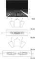
- a projection device 8 comprising a first module 9 located on one side of the optical axis, a second module 10 located on the opposite side of the optical axis and a third module 11, or central module, located between the two previous ones.
- the result of the projection from the first and second modules 9, 10 corresponds to the isolux curves schematized in figure 10b .
- the first and second sub-beams 13, 14 coming respectively from the first and second modules 9, 10 have an overlap, preferably around a vertical plane passing through the optical axis.
- the overall result of the projection is a beam which has little discontinuity in the definition of its envelope.
- FIG 11a shows a different arrangement of the modules 9, 10 of the projection device 8 in which the inclination of the modules 9, 10 has been modified relative to the position of the central module 11.
- the result of this modification of position is revealed in figure 11b .
- the isolux curves corresponding to the projection of the first sub-beam 13 and to the projection of the second sub-beam 14 respectively from the first and second modules 9, 10 are further apart along a beam width direction. In the example shown, this spacing is such that the first and second sub-beams 13, 14 no longer overlap. Consequently, a zone of lesser illumination can be created in the intermediate space.
- the curves shown in Figures 10b and 11b do not show the third sub-beam 15 from the third module 11 for the sake of simplification.
- the invention is not limited to a method of modifying the relative configuration of the sub-beams of the projection device 8 of the dipped beam 3.
- the modification can be produced by a movement of a module or a part thereof.
- the modification of the position of the output diopter of a module for example by rotation, can be sufficient to carry out the configuration modification.
- This can be a rotation applied to a projection lens or to an output reflector.
- the mobility of the module or of a part thereof can in particular be a pivot along one or more axes.
- the mobility of the sub-beam considered is oriented along a vertical axis.
- a movement of two modules 9, 10 is also carried out. These movements can be substantially symmetrical, that is to say that, following a vertical pivot, the modules 9, 10 are moved by an equivalent or symmetrical angular sector around a vertical plane containing the optical axis.
- the third module 11 could itself be mobile, for example following a mobility in pivot of horizontal axis to lower or slightly raise the projection of the third sub-beam 15 so as to modify the amplitude and/or the position of the zone of lesser illumination 5.
- this aspect of the invention makes it possible to modify the shape and the possible overlap of the sub-beams constituting the dipped beam 3. For example, it is possible to increase or decrease the width of the dipped beam 3 or increase or decrease the overlap of several sub-beams so as to vary and in particular reduce the resulting light intensity at certain locations, which ensures the creation of a zone of lesser illumination 5.
- more than three modules are present in the projection device 8 of the dipped beam 3.
- several modules are located on one side of the optical axis and several modules are located on the other side of the optical axis.
- module 9 would be replaced by a group of modules comprising at least two modules.
- the groups of modules located on either side of the optical axis have mobility along the same pivot axis, the angular sector of this mobility being able to be identical or different.
- module mobility means the mobility of at least part of each module so as to change the direction of the corresponding sub-beam.
- the projection device is equipped with a first module or group of modules 9 identical to the second module or group of modules 10, or that each of these two modules or group of modules is clearly identified and arranged to form a left module or group of modules and a right module or group of modules.
- the modules may be equipped with one or more lenses.
- the system of the invention can be positioned so as to modify the configuration of the dipped beam 3. This modification is in the direction of creating or increasing the surface area of the zone of lesser illumination 5.
- the additional beam 12 examples relating to navigation or the display of safety information have been previously given for information purposes.
- FIG. 12 to 14 also present another embodiment of the invention. It should be noted that all or part of the features presented in the embodiment of these figures can be combined with all or part of the features presented in the case of the embodiments set out above. While in the previous embodiments it was preferred to use a right group of modules and a left group of modules having substantially the same characteristics, i.e. final beams substantially identical in shape and size, the embodiment of the Figures 12 to 14 allows, in a preferred case, to differentiate the shape of a right beam and the shape of a left beam. More particularly, it is advantageous that the shape of these two beams ensures at least in part the generation of the zone of lesser illumination 5.
- the optical axis A intersects the illustration plane at an intersection with a vertical axis 7 and a horizontal line 2.
- a first beam 26, located towards the left, is illustrated and is generally positioned in a quadrant delimited by the horizontal line 2 in the upper part and the vertical axis 7 on the right edge.
- a second beam 27, located towards the right, is also illustrated and is generally positioned in a quadrant delimited by the horizontal line 2 in the upper part and the vertical axis 7 on the left edge.
- the left beam 26 and the right beam 27 are preferably but not limited to symmetrical to each other relative to a vertical plane containing the optical axis A and the vertical line 7. This plane corresponds advantageously a mid-plane of the vehicle. But the beams 26, 27 are each preferably not symmetrical in themselves to preserve a portion of lesser illumination towards the center of the final dipped beam.
- At least one, but preferably both, beams 26, 27 preserve a portion of lesser illumination in an area located in the vicinity of the optical axis A, this portion of lesser illumination participating in the zone of lesser illumination 5.
- the beams 26, 27 each produce an illumination bordered in the upper part by the horizontal line 2, corresponding to the horizon line. This illumination starts from a lateral edge, towards the outside of the vehicle, to a central edge which is preferably located at the level of the optical axis A.
- a majority portion of the illumination produced may have a convex profile directed downwards so as to produce a curved shape such as in the illustration of the figure 12 .
- this convexity does not continue to the lateral edge 28 in the vicinity of the optical axis A, so as to leave a hole in the illumination produced.
- a portion of the lateral edge 28 has at this level a narrowing, for example formed by a concave curvilinear line, or even an inclined portion, so as to release a portion of lesser illumination when the beam 26 or 27 approaches the zone located at the level of the vertical 7.
- each of these two beams produces an essentially horizontal portion of beam in the vicinity of the optical axis A, for example in the form of a handle as in the case of the illustrations of the figure 12
- the illustrated configuration is not limiting and any shape of beam 26, 27 making it possible to clear an unilluminated or less illuminated space at the lateral edge 28 of these beams near the vertical line 7 may be suitable.
- the beams 26, 27 overlap at the level of the vertical plane passing through the optical axis A.
- the beam 26 is called a left beam in the sense that it is mainly located on a left side of a plane passing vertically through the optical axis A. This does not exclude that the left beam partially illuminates a right side of said plane. It is the opposite for beam 27, called right beam.
- FIG. 13 Another representation of a result produced by the projection of the two beams 26, 27 is given in figure 13 in top view.
- the beams 26, 27 converge slightly towards infinity so as to produce a central illumination; but, it preserves a zone of lesser illumination 5 around the optical axis A near the vehicle 1.
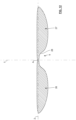
- FIG 14 give an example of a group 20 of modules that can be used to form the left beam 26 described above. It is understood that a group 20 of modules can be formed in a corresponding manner, and advantageously symmetrically, for the right beam 27.
- the group 20 comprises a fairing 25 for supporting and enveloping at least one module for generating the beam 26. In the example illustrated, three modules 21, 22, 23 are present.
- the module 23 can be used to generate the portion of the beam 26 comprising the narrowing in the direction of the vertical plane containing the optical axis.
- This narrowing can for example be obtained by means of a suitable lens and/or a cover and/or a reflector of a shape making it possible not to project light beams, or to limit such projection, in the area corresponding to the narrowing. Any technique for forming a cut-off can be used in this context.
- the other modules 21, 22 can be used to provide lighting in the remainder of the beam 26.
- the modules 21, 22, 23 are each equipped with a light source 24 for example in the form of LEDs.
- the example given to the figure 14 is not limiting and a group of a single module could suffice on each side of the vehicle 1. Furthermore, this embodiment is compatible with mobility of all or part of the modules, so as to change the configuration of the beams 26, 27 according to the desired mode of use. For example, the beams 26, 27 can be brought closer together in the direction of the optical axis A so as to reduce or eliminate the zone of lower illumination 5.
Landscapes
- Engineering & Computer Science (AREA)
- General Engineering & Computer Science (AREA)
- Physics & Mathematics (AREA)
- Microelectronics & Electronic Packaging (AREA)
- Optics & Photonics (AREA)
- Mechanical Engineering (AREA)
- Lighting Device Outwards From Vehicle And Optical Signal (AREA)
- Non-Portable Lighting Devices Or Systems Thereof (AREA)
Description
- La présente invention est relative notamment à un système d'éclairage.
- Une application préférée concerne l'industrie automobile, pour l'équipement de véhicules, en particulier pour la réalisation de dispositifs susceptibles de pouvoir émettre des faisceaux lumineux, encore appelés fonctions d'éclairage, répondant en général à des réglementations.
- Notamment l'invention peut permettre la production d'un faisceau du type croisement seul ou en combinaison avec une fonction de signalisation et/ou d'éclairage, d'intensité bien plus faible.
- Les dispositifs d'éclairage et de signalisation connus sont jusqu'à présent prévus pour émettre par exemple :
- un faisceau de croisement, dirigé vers le bas, encore parfois appelé faisceau de code et utilisé en cas de présence d'autres véhicules sur la chaussée;
- un faisceau de route dépourvu de coupure, et caractérisé par un éclairement maximal dans l'axe du véhicule ;
- un faisceau d'éclairage pour temps de brouillard, caractérisé par une coupure plate et une grande largeur d'éclairement ;
- un faisceau de signalisation pour la circulation en ville, encore appelé lampe de ville.
- Le document
US 2007/103923 A1 décrit un dispositif d'éclairage pouvant générer un faisceau de croisement et comprenant une pluralité de modules générant des sous-faisceaux afin d'adapter l'éclairage aux conditions dans lesquelles se trouve le véhicule. - Le faisceau de croisement est fondamental dans la mesure où sa bonne définition conditionne à la fois la qualité de l'éclairage et l'absence, ou la réduction, de la gêne occasionnée par le flux lumineux produit pour les véhicules alentours. Actuellement, les feux de croisement sont essentiellement définis dans cette optique, avec, en particulier, le recours à des coupures parfois complexes en haut de faisceau, de sorte à limiter précisément ou éviter l'éclairement au-dessus de la ligne d'horizon, et à concevoir au mieux une zone de projection de lumière à proscrire car susceptible de gêner le conducteur d'un véhicule croisé.
- Le document
JP 2014 189198 A - Il existe cependant un besoin pour améliorer la définition des faisceaux de croisement.
- L'invention s'inscrit dans ce cadre.
- Elle concerne en particulier un système d'éclairage pour véhicule automobile selon la revendication 1, ledit système comportant un dispositif de projection d'un faisceau de croisement dans une zone de projection.
- Selon l'invention, ce système est tel que le dispositif de projection est configuré pour que le faisceau de croisement comprenne une zone de moindre illumination située à l'intérieur de la zone de projection. Ainsi, le feu de croisement présente une intensité lumineuse modulée selon le lieu de projection dans la zone globale de projection. Cela est avantageux dans certaines circonstances. L'une d'entre-elles concerne les cas de fortes précipitations, la zone de moindre illumination ayant un effet moins réfléchissant pour le conducteur. Une autre situation est relative à la projection concomitante d'un faisceau additionnel. En effet, la zone de moindre illumination peut ménager un espace propice à la projection d'un autre faisceau. Ce faisceau peut notamment permettre une signalisation, étant par exemple doté d'un motif du type pictogramme. Alors que l'on aurait communément pensé à superposer, au-dessus du faisceau de croisement, un faisceau de plus forte intensité visant une signalisation, l'invention offre une solution moins consommatrice d'énergie et plus flexible. En effet, la zone de moindre illumination du faisceau de croisement peut être le lieu d'une projection additionnel de faible intensité, en particulier moindre que celle du feu de croisement. Cette caractéristique offre en outre un éventail de technologies utilisables pour la projection du faisceau additionnel. Il peut s'agir de techniques de projection de faisceaux sous forme de rayons pixélisés. Ces techniques, qui ne sont pas toujours puissantes en termes de flux lumineux, offrent une grande souplesse de choix de formes de faisceaux. Elles sont ici utilisables, grâce à la zone de moindre illumination de l'invention.
- Selon une caractéristique optionnelle de l'invention, on peut prévoir que la zone de moindre illumination comprend une limite supérieure décalée angulairement par rapport à une limite supérieure du faisceau de croisement d'une valeur d'angle d'au moins 5°, préférentiellement d'au moins 6°, par rapport au point d'émission du faisceau de croisement, dans un plan vertical et longitudinal.
- Selon l'invention, le système comprend un dispositif de projection d'un faisceau additionnel formé de rayons pixélisés et configuré pour illuminer une zone couvrant au moins en partie la zone de moindre illumination. Cette technologie offre une grande résolution et permet de produire différentes formes de faisceau additionnel. La zone de moindre illumination comprend de préférence mais non limitativement une bordure supérieure inclinée d'au moins 5°, préférentiellement 6°, relativement à un plan horizontal.
- Ainsi, l'invention permet une projection additionnelle, à l'intérieur de l'espace occupé par le faisceau de croisement. Comme une zone de moindre intensité est présente, ce faisceau additionnel peut être moins éclairant que le faisceau code tel que projeté en dehors de la zone de moindre illumination.
- Selon l'invention, le dispositif de projection du faisceau de croisement comporte au moins une pluralité de modules aptes chacun à produire un sous-faisceau participant au faisceau de croisement, le dispositif de projection du faisceau de croisement étant configuré de sorte que la position relative d'au moins deux sous-faisceaux soit modifiable entre au moins une position dans laquelle la zone de moindre illumination est présente et au moins une autre position dans laquelle la zone de moindre illumination est absente.
- Cette possibilité permet de placer le système de l'invention dans au moins deux configurations différentes de fonctionnement. La première peut représenter la position de feu de croisement traditionnel, sans zone de moindre illumination. La deuxième correspond à la présence de zone de moindre illumination. Ainsi, le système peut évoluer entre deux modes de fonctionnement.
- D'autres caractéristiques optionnelles du système d'éclairage et/ou de signalisation selon l'invention, qui peuvent être mises en œuvre de façon combinée selon toutes associations entre-elles ou de manière alternative, sont indiquées ci-après :
- le faisceau additionnel est configuré pour produire le contour d'au moins un pictogramme ;
- la zone de moindre illumination est entièrement couverte par le faisceau additionnel ;
- le dispositif de projection d'un faisceau additionnel comprend un système à matrice de micro miroirs ;
- la zone de moindre illumination est symétrique autour d'un plan vertical passant par l'axe optique du dispositif de projection du faisceau de croisement ;
- la zone de moindre illumination couvre un secteur angulaire de moins de 10° en section horizontale ;
- la pluralité de modules comprend au moins un module configuré pour produire un sous-faisceau mobile en rotation ;
- la pluralité de modules comprend au moins un premier groupe d'au moins un module situé d'un premier côté de l'axe optique du dispositif de projection de faisceau de croisement, et un deuxième groupe d'au moins un module situé d'un autre côté dudit l'axe optique ;
- le premier groupe est éventuellement configuré pour éclairer uniquement du premier côté de l'axe optique et le deuxième groupe est configuré pour éclairer uniquement du deuxième côté de l'axe optique
- chacun parmi le premier groupe et le deuxième groupe peut être configuré pour produire un faisceau présentant une portion de moindre illumination sur un bord latéral de faisceau situé du côté de l'axe optique, les portions de moindre illumination participant à former la zone de moindre illumination.
- chacun parmi le premier groupe et le deuxième groupe peut être configuré pour produire un faisceau présentant un profil, suivant un plan vertical perpendiculaire à l'axe optique, avec un rétrécissement en hauteur en direction de l'axe optique ;
- le premier groupe et le deuxième groupe sont éventuellement configurés pour produire des faisceaux symétriques l'un de l'autre relativement à un plan vertical passant par l'axe optique.
- la position relative des sous-faisceaux produits respectivement par les modules du premier groupe et par ceux du deuxième groupe peut être modifiable ;
- le système comprend un troisième groupe d'au moins un module situé suivant l'axe optique.
- L'invention est aussi relative à un véhicule équipé d'au moins un système tel qu'introduit ci-dessus. Le véhicule peut comprendre deux systèmes, chacun au niveau d'un côté différent de la partie frontale du véhicule.
- Le système peut être intégré dans un bloc de projecteur de phare.
- D'autres caractéristiques, buts et avantages de la présente invention apparaîtront à la lecture de la description détaillée qui suit, et en regard des dessins annexés donnés à titre d'exemples non limitatifs et sur lesquels :
- la
figure 1 montre schématiquement le lieu d'une projection d'un faisceau de croisement et la présence d'une zone de moindre illumination, en vue de profil. - la
figure 2 montre cette projection en vue de dessus ; - la
figure 3 illustre dans un plan vertical le faisceau de croisement, ici pour l'exemple à coupure ; - la
figure 4 montre un premier mode de réalisation d'un dispositif de projection du faisceau de croisement ; - la
figure 5 est une courbe isolux du résultat de la projection du faisceau de croisement ; - la
figure 6 présente un exemple de module optique à matrice de micro-miroirs ; - la
figure 7 montre une forme possible du faisceau additionnel ; - la
figure 8 représente l'association du faisceau de croisement et du faisceau additionnel ; - la
figure 9 est une vue de la projection d'un pictogramme dans le faisceau additionnel durant la projection du faisceau de croisement ; - la
figure 10a montre un deuxième mode de réalisation d'un dispositif de projection du faisceau de croisement, ce dispositif étant dans une première position ; - la
figure 10b est une courbe isolux de deux sous-faisceaux du faisceau projeté dans cette première position ; - la
figure 11a montre une deuxième position du dispositif de projection dans le deuxième mode de réalisation ; - la
figure 11b est une courbe isolux de deux sous-faisceaux du faisceau projeté dans cette deuxième position ; - la
figure 12 illustre une vue en coupe verticale d'un exemple de projection produit par un système selon un autre mode de réalisation de l'invention ; - la
figure 13 s'inscrit dans le mode de réalisation de lafigure 12 et montre le résultat d'une projection, vu de dessus ; - la
figure 14 est un exemple de réalisation d'un groupe de modules pouvant former une partie du faisceau global souhaité, pour le mode de réalisation desfigures 12 et13 notamment. - Dans les caractéristiques exposées ci-après, les termes relatifs à la verticalité, l'horizontalité et à la transversalité, ou leurs équivalents, s'entendent par rapport à la position dans laquelle le système d'éclairage est destiné à être monté dans un véhicule. Les termes « vertical » et « horizontal » sont utilisés dans la présente description pour désigner des directions, suivant une orientation perpendiculaire au plan de l'horizon pour le terme « vertical », et suivant une orientation parallèle au plan de l'horizon pour le terme « horizontal ». Elles sont à considérer dans les conditions de fonctionnement du dispositif dans un véhicule. L'emploi de ces mots ne signifie pas que de légères variations autour des directions verticale et horizontale soient exclues de l'invention. Par exemple, une inclinaison relativement à ces directions de l'ordre de + ou - 10° est ici considérée comme une variation mineure autour des deux directions privilégiées.
- Le terme « bas » ou partie basse s'entend généralement d'une partie d'un élément de l'invention située, suivant un plan vertical, en dessous de l'axe optique. Le terme « haut » ou partie haute s'entend d'une partie d'un élément de l'invention située, suivant un plan vertical, au-dessus de l'axe optique. Le terme « parallèle » ou la notion d'axes ou lignes confondus s'entend ici notamment avec les tolérances de fabrication ou de montage, des directions sensiblement parallèles ou des axes sensiblement confondus entrent dans ce cadre.
- Dans le cadre de l'invention, on entend par faisceau de croisement un faisceau employé lors de la présence de véhicules croisés et/ou suivis et/ou d'autres éléments (individus, obstacles...) sur la chaussée ou à proximité. Ce faisceau présente une direction moyenne descendante. Il peut être éventuellement caractérisé par une absence de lumière au-dessus d'un plan incliné de 1% vers le bas du côté de la circulation dans l'autre sens, et d'un autre plan incliné de 15 degrés par rapport au précédent du côté de la circulation dans le même sens, ces deux plans définissant une coupure conforme à la réglementation européenne. Cette coupure supérieure descendante a pour but d'éviter d'éblouir les autres usagers présents dans la scène de route s'étendant devant le véhicule ou sur les bas-côtés de la route.
- Le faisceau de croisement, autrefois issu d'un projecteur simple, a connu des évolutions, la fonction de croisement pouvant être couplée avec d'autres caractéristiques d'éclairage. On a ainsi récemment élaboré de nouvelles fonctions, désignées comme fonctions élaborées et regroupées sous le nom d'AFS (abréviation pour « Advanced Frontlighting System » en anglais), qui proposent notamment d'autres types de faisceaux. Il s'agit notamment de la fonction dite BL (Bending Light en anglais pour éclairage de virage), qui peut se décomposer en une fonction dite DBL (Dynamic Bending Light en anglais pour éclairage mobile de virage) et une fonction dite FBL (Fixed Bending Light en anglais pour éclairage fixe de virage). Ces fonctions d'éclairage de virage sont utilisées en cas de circulation en courbe, et elles sont réalisées au moyen de projecteurs qui émettent un faisceau lumineux dont l'orientation horizontale varie lorsque le véhicule se déplace sur une trajectoire incurvée, de façon à éclairer correctement les portions de route qui sont destinées à être abordées par le véhicule et qui se trouvent non pas dans l'axe du véhicule, mais dans la direction qu'il est sur le point d'emprunter, résultant de l'angle imprimé aux roues directrices du véhicule par son conducteur. Une autre fonction est dite Town Light en anglais, pour éclairage de ville. Cette fonction assure l'élargissement d'un faisceau de type feu de croisement tout en diminuant légèrement sa portée. La fonction dite Motorway Light en anglais, pour éclairage d'autoroute, réalise quant à elle la fonction autoroute. Cette fonction assure une augmentation de la portée d'un feu de croisement en concentrant le flux lumineux du feu de croisement au niveau de l'axe optique du dispositif projecteur considéré. On connait aussi la fonction dite Overhead Light en anglais, pour feu de portique. Cette fonction assure une modification d'un faisceau de feu de croisement typique de telle sorte que des portiques de signalisation situés au-dessus de la route soient éclairés de façon satisfaisante au moyen des feux de croisement. Une autre variante de feu de croisement est la fonction dite AWL (Adverse Weather Light en anglais, pour feu de mauvais temps). Cette fonction assure une modification d'un faisceau de feu de croisement de telle sorte que le conducteur d'un véhicule circulant en sens inverse ne soit pas ébloui par le reflet de la lumière des projecteurs sur la route mouillée. De plus, lorsque l'éclairage de croisement est en fonction, l'assiette du véhicule peut subir des variations plus ou moins importantes, dues par exemple à son état de charge, son accélération ou sa décélération, qui provoquent une variation de l'inclinaison de la coupure supérieure du faisceau, ayant pour résultat soit d'éblouir les autres conducteurs si la coupure se trouve relevée, soit d'éclairer insuffisamment la route si la coupure se trouve abaissée. Il est alors connu d'utiliser un correcteur de portée, à commande manuelle ou automatique, pour corriger l'orientation des projecteurs de croisement. D'une manière générale, le faisceau de croisement visé par l'invention comprend le faisceau code conforme à la réglementation et ses évolutions dont celles décrites ci-dessus. D'une façon générale, le faisceau de croisement peut s'entendre de tout faisceau descendant et/ou éclairant la chaussée sans dépasser significativement la ligne d'horizon.
- Dans la description qui suit, des numéros de référence similaires seront utilisés pour décrire des concepts similaires à travers des modes de réalisation différents de l'invention. Sauf indication spécifique du contraire, des caractéristiques techniques décrites en détail pour un mode de réalisation donné peuvent être combinés à tout ou partie des caractéristiques techniques décrites dans le contexte d'autres modes de réalisation décrits à titre exemplaire et non limitatif.
- La
figure 1 illustre schématiquement un exemple de projection descendante à l'avant d'un véhicule automobile 1. Dans cet exemple qui schématise la projection d'un feu de croisement 3, ce dernier est projeté en-deçà d'un plan horizontal 2 de sorte à impacter la chaussée 4 à l'avant d'un véhicule automobile 1. On peut se reporter aux indications données précédemment à propos des faisceaux de croisement en ce qui concerne les caractéristiques de projection de ce faisceau. Globalement, le faisceau de croisement 3 comporte une enveloppe extérieure avec une limite inférieure 3a définissant une limite de l'enveloppe du faisceau la plus proche du véhicule et correspondant à la plus forte inclinaison relativement au plan horizontal 2 et une limite supérieure 3b correspondant à une limite supérieure de l'enveloppe du faisceau 3, la moins inclinée relativement au plan horizontal 2. - Comme précédemment indiqué, un aspect de l'invention est de proposer une définition spécifique ou évolutive du faisceau de croisement 3. Dans ce cadre, la
figure 1 schématise également la présence d'une zone 5 de moindre illumination. Telle que schématisée, la zone 5 est délimitée par une limite inférieure 5a et une limite supérieure 5b représentées en pointillés et définissant, dans un plan longitudinal et vertical perpendiculaire au plan horizontal 2, les inclinaisons respectivement maximale et minimale de l'enveloppe de la zone 5. - Par moindre illumination, on entend que l'éclairement lumineux moyen dans la zone de moindre illumination 5 est inférieur d'au moins 70%, préférentiellement au moins 80%, plus préférentiellement au moins 90%, de préférence au moins 97%, de manière tout à fait préférée d'au moins 99%, à l'éclairement lumineux moyen dans le reste de la zone de projection du faisceau de croisement 3. Autrement dit, on cherche à n'avoir quasiment pas de lumière dans cette zone de moindre illumination. On relèvera ainsi des valeurs moyennes d'intensité lumineuse inférieures à 400 candelas, de préférence inférieures à 100 candelas, avantageusement inférieures à 50 candela, plus préférentiellement inférieures à 30 candela dans cette zone de moindre illumination tandis que dans le reste du faisceau, et en particulier à proximité immédiate de cette zone, les valeurs seront supérieures à au moins 2000 voire 3000 candelas.
- La position de cette zone de moindre illumination 5 peut varier à l'intérieur du faisceau de croisement 3, et à titre d'exemple qui sera repris ci-après, on pourrait avoir une limite inférieure 5a de la zone 5 confondue avec la limite inférieure 3a du faisceau de croisement 3. Il est particulièrement intéressant, notamment dans l'utilisation de cette zone de moindre illumination pour la projection d'un faisceau additionnel 12 que l'on souhaite rendre visible pour le conducteur, que la zone de moindre illumination soit disposée à l'intérieur du faisceau de croisement à distance suffisante de la limite supérieure 3b du faisceau de croisement 3 pour être bordée dans sa partie supérieure par une zone de forte illumination. Notamment, on pourra prévoir que la zone de moindre illumination 5 comprend une limite supérieure 5b décalée angulairement par rapport à la limite supérieure 3b du faisceau de croisement 3, d'un angle α (visible sur la
figure 1 ) par rapport au point d'émission du faisceau de croisement dans le plan longitudinal et vertical illustré sur lafigure 1 , l'angle α ayant une valeur d'au moins 5°. - La
figure 2 est une vue de dessus d'un véhicule automobile 1 et d'une zone située à l'avant de ce véhicule. Dans cet exemple, on a représenté en pointillés la projection d'un faisceau additionnel 12 à l'intérieur du faisceau de croisement 3, le faisceau additionnel 12 pouvant être configuré de sorte à recouvrir en tout ou partie la zone 5 précédemment présentée. - Un intérêt de l'invention est de faire en sorte que le faisceau additionnel 12 tire profit des caractéristiques de la zone 5 pour réaliser un éclairage ou une signalisation spécifique à l'intérieur du faisceau de croisement 3. Avantageusement, la formation de la zone 5 est réversible en ce sens que la définition du faisceau de croisement peut être modifiée pour supprimer cette zone, ou encore la réduire, la déplacer, l'agrandir ou modifier sa forme. On donne ultérieurement dans la description des exemples de réalisation de cette modification de faisceau.
- La zone 5 est de moindre illumination relativement au reste du faisceau de croisement 3, c'est-à-dire qu'elle se présente sous une forme relativement ombrée à l'intérieur de la zone de projection du faisceau de croisement 3. Le faisceau additionnel 12 peut réaliser une projection au moins au niveau de cette zone 5 de sorte par exemple à produire une partie complémentaire du faisceau de croisement 3 relativement à une partie projetée par un projecteur de base du faisceau de croisement 3 ou encore pour réaliser une projection parallèle au feu de croisement par exemple pour produire une signalisation tel que cela sera décrit en détail plus loin.
- La
figure 3 est une autre illustration de l'insertion, dans un faisceau de croisement qui peut être traditionnel, d'un faisceau additionnel 12. A cette figure, le plan horizontal 2 est représenté sous forme de ligne d'horizon sur un plan vertical contenant un axe vertical 7 passant par l'axe optique passant par le point A du système d'éclairage. De façon conventionnelle, la zone illuminée 6 du faisceau de croisement 3 peut typiquement présenter une bordure supérieure sensiblement au niveau du plan horizontal 2 de la ligne d'horizon et dotée d'une première portion correspondant à une coupure haute 6a légèrement au-dessus de l'horizon, une deuxième portion dénommée coupure basse 6c légèrement en deçà de la ligne d'horizon, ces deux portions étant jointes par une portion intermédiaire correspondant à un virage 6b, ici sous la forme d'une portion coudée, notamment linéaire, rejoignant les portions 6a et 6c. Dans l'exemple représenté mais de manière non limitative, le virage 6b passe par l'axe optique illustré par le point A. Dans sa partie basse, la zone illuminée 6 du faisceau de croisement 3 peut globalement disposer d'une enveloppe sensiblement en portion curviligne convexe, par exemple en arc de cercle ou en portion en portion pseudo-elliptique. On comprend que cette configuration permet globalement d'éclairer une zone à l'avant du véhicule automobile 1 qui est située relativement proche du véhicule et qui évite une projection ascendante susceptible d'éblouir des véhicules croisés ou suivis par le véhicule équipé du système de l'invention. - Dans le même temps, la présente invention peut permettre une fonctionnalité supplémentaire comme la définition d'une zone spécifique à l'intérieur de la zone illuminée 6 précédemment décrite, par exemple pour la projection d'un faisceau additionnel 12 schématisé par les pointillés en forme de cadre en
figure 3 uniquement par souci d'explication. La forme de l'enveloppe du faisceau additionnel 12 n'est en effet pas limitée. - En vue de réaliser la projection du faisceau de croisement 3 définissant la zone illuminée 6, une possibilité est l'utilisation d'un dispositif de projection 8 qui peut être monobloc ou non et qui comporte un ou plusieurs modules optiques 9, 10, 11 ici représentés dans un même ensemble en disposant néanmoins chacun d'un élément optique de sortie individuel.
- D'une manière générale, la présente invention peut utiliser, pour tout ou partie du dispositif de projection du faisceau de croisement, en particulier au niveau des modules 9, 10, 11, une source lumineuse par exemple du type diode électroluminescente encore communément appelée LED. Notamment, cette LED peut être dotée d'au moins une puce apte à émettre une lumière d'intensité avantageusement ajustable selon la fonction d'éclairage et/ou de signalisation à réaliser. Par ailleurs, le terme source lumineuse s'entend ici d'un ensemble d'au moins une source élémentaire telle une LED apte à produire un flux conduisant à générer en sortie du dispositif de l'invention au moins un flux de sortie remplissant au moins une fonction souhaitée. La source est associée généralement à un support, des moyens de connectique ainsi qu'à des moyens de dissipation de chaleur. Préférentiellement, la source est configurée pour émettre suivant une direction moyenne d'émission qui est perpendiculaire au plan de la puce de la LED si cette technique de source est employée. Les modules peuvent comprendre un dioptre de sortie par lequel le faisceau est émis, par exemple sous forme d'une surface externe de lentille. D'autres types de sources sont aussi envisageables dans l'invention, telle une ou plusieurs sources laser, notamment pour les dispositifs à rayons pixélisés tels ceux à matrice micro-miroirs décrits plus loin.
- Ainsi, en revenant à la définition du faisceau de croisement 3, un dispositif de projection 8 tel que représenté en
figure 4 et présentant trois modules 9, 10, 11 permet par exemple la formation d'un faisceau dont une courbe isolux est représentée enfigure 5 . A cette figure, correspondant à une projection à une distance donnée du véhicule, on note la formation d'un premier sous-faisceau 13 situé du côté droit de la courbe isolux et par exemple sous forme de courbes fermées ovales et allongées en lignes parallèles sensiblement dans une portion de l'espace située d'un côté de l'axe vertical 7. Ce premier sous-faisceau 13 peut correspondre au résultat de la projection issue du premier module optique 9. De manière relativement similaire voire symétrique, un deuxième sous-faisceau 14 est projeté et se situe dans le cas de lafigure 5 de l'autre côté de l'axe vertical 7 relativement au premier sous-faisceau 13. Ce deuxième sous-faisceau 14 peut correspondre au résultat de la projection issue du deuxième module optique 10. On comprend que la combinaison des premier et deuxième sous-faisceaux permet de construire un ensemble plus global sensiblement élargi. De sorte à obtenir une zone d'illumination plus intense, particulièrement avantageusement au niveau de l'axe optique, un troisième sous-faisceau 15 peut être projeté bien que cet exemple ne soit pas limitatif. A cet effet, le troisième sous-faisceau 15 est ici centré autour de l'axe vertical 7 de sorte à produire une zone d'intensité plus importante sensiblement vers le milieu de la largeur du faisceau de croisement 3. - Avantageusement, la projection du troisième sous-faisceau 15 est configurée pour que la zone d'intensité plus importante soit située au voisinage de la ligne d'horizon du plan horizontal 2 et légèrement en deçà de celle-ci. Par exemple, la zone correspondant au troisième sous-faisceau 15 peut correspondre à une hauteur comprise entre 20 et 50% de la hauteur du faisceau de croisement 3 globale suivant l'axe vertical 7. Le troisième sous-faisceau 15 peut être le résultat de la projection produite par le troisième module optique 11 représenté en
figure 4 . On notera que dans l'exemple de lafigure 5 , les courbes isolux sont ainsi construites qu'une inflexion est présente, dans l'exemple sensiblement autour de l'axe vertical 7 de sorte qu'une zone moins illuminée 5 voire non illuminée est présente dans le faisceau de croisement 3. Dans le cas représenté, la zone 5 couvre une partie basse centrale de l'enveloppe de la zone illuminée si bien que, contrairement à la représentation de lafigure 1 , la limite inférieure 3a du faisceau de croisement 3 y est confondue avec la limite inférieure 5a de la zone moins illuminée 5. Ainsi, la présente invention n'implique pas que la zone 5 soit intégralement entourée d'une zone plus illuminée. En l'espèce, dans le cas de lafigure 5 , la zone moins illuminée 5 correspond à une partie basse centrale de l'enveloppe du faisceau de croisement 3, la partie inférieure de la zone de moindre illumination 5 n'étant pas bordée par une partie plus illuminée du faisceau de croisement 3. - Suivant une possibilité, la zone de moindre illumination 5 peut être utilisée pour limiter l'inconfort visuel du conducteur dans certaines situations de conduite en particulier en cas de fortes précipitations. En effet, ces situations ont tendance à produire une réflexion partielle du faisceau de croisement susceptible d'éblouir le conducteur. La présence d'une zone de moindre illumination, en tant que telle, permet de limiter ce phénomène d'éblouissement.
- L'invention permet d' exploiter la zone de moindre illumination 5 pour opérer la projection du faisceau additionnel 12 évoqué précédemment. A cet effet, on emploie un dispositif de projection 16 d'un faisceau additionnel 12 formé de rayons pixélisés. Ce dispositif est conçu pour former une projection du faisceau additionnel 12 au moins en partie dans la zone de moindre illumination 5. Ce faisceau additionnel 12 peut couvrir intégralement la zone 5 ou uniquement partiellement. Il est par ailleurs entendu que la présente invention peut permettre la génération d'une pluralité de zones de moindre illumination 5 et que les explications données en référence à la projection d'un faisceau additionnel 12 peuvent être reproduites pour la projection d'une pluralité de faisceaux additionnels 12 par exemple chacun dédié à une zone de moindre illumination 5.
- A propos du dispositif de projection 16 d'un faisceau additionnel 12, les techniques actuelles permettent de réaliser une projection d'un faisceau, par exemple collimaté ou convergent, formé d'une pluralité de rayons pouvant être individuellement commandés de sorte à produire une définition de faisceaux particulièrement précise et modifiable. En ce sens, on pourra utiliser un système d'imagerie pixélisée et digitale.
- Les termes « système d'imagerie pixélisée et digitale », « système d'imagerie à rayons pixélisés » ou leurs équivalents ont pour définition un système émetteur d'un faisceau lumineux, ledit faisceau lumineux étant formé d'une pluralité de sous faisceaux lumineux, chaque sous faisceau lumineux pouvant être piloté indépendamment des autres sous faisceau lumineux. Chaque sous faisceau pilotable indépendamment forme un rayon pixélisé. Ces systèmes peuvent être par exemple des matrices à micro-miroirs, notamment pilotables en rotation, ou encore des dispositifs à cristaux liquides. Une autre technologie de formation de rayons pixélisés est munie d'une source laser dont le rayon est renvoyé par un dispositif de balayage sur une surface disposée au foyer d'une optique de projection et composée d'une pluralité d'éléments de matériau luminophore, usuellement désignés sous le terme de phosphore. Ces éléments luminophores réémettent de la lumière blanche qui est projetée par une lentille pour former un faisceau d'éclairage sur la route en avant du véhicule. Les segments de matériau luminophore sont disposés entre la source laser et la lentille de projection, au foyer de cette lentille.
- La
figure 6 illustre un exemple non limitatif de système d'imagerie pixélisée et digitale 16 appelé en termes Anglo-Saxon « Digital Micromirror Device » (DMD), c'est-à-dire un dispositif à micro-miroirs, également appelé une matrice à micro-miroirs. - Ce système comprend une source lumineuse 17, pouvant être par exemple des LEDs ou bien des diodes lasers, ou toute sorte de sources lumineuses. Cette source lumineuse 17 émet un faisceau lumineux avantageusement en direction d'un réflecteur 18. Ce réflecteur 18 est de préférence configuré pour concentrer le flux de lumière incident sur une surface comportant la matrice de micro-miroirs 19.
- De manière avantageuse, le réflecteur 18 est configuré pour que l'ensemble des micro-miroirs soient éclairés par le faisceau lumineux réfléchi par le réflecteur 18. Le réflecteur 18 peut avoir, suivant au moins un plan de section, un profil pseudo elliptique ou pseudo parabolique.
- Une fois réfléchi par une partie au moins des micro-miroirs, le faisceau lumineux passe au travers d'un dioptre 20. De manière avantageuse, ce dioptre 20 peut être une lentille convergente par exemple.
- Comme indiqué, après réflexion du faisceau lumineux sur le réflecteur 18, celui-ci vient se concentrer sur la matrice de micro-miroirs 19. De manière préférentielle, les micro-miroirs disposent chacun de deux positions de fonctionnement, une position dite active dans laquelle ils réfléchissent le faisceau lumineux incident en direction du dioptre 20, et une position dite passive dans laquelle ils réfléchissent le faisceau lumineux incident en direction d'un élément absorbeur de rayonnement lumineux non représenté dans la
figure 6 . - Ce type de dispositif permet de disposer en sortie du dioptre 20 d'un faisceau lumineux hautement résolu pixélisé et digitalisé : chaque pixel ou rayons pixélisé composant ce faisceau correspond à un micro-miroir, et il est alors possible d'activer ou non ces micro-pixels en simplement pilotant les micro-miroirs. Cette particularité permet alors de dessiner au besoin la forme du faisceau lumineux en sortie du dioptre 20 selon les besoins de l'invention.
- Par exemple, il est possible de n'activer qu'une partie des micro-miroirs afin de former une coupure au niveau du faisceau lumineux en sortie du dioptre 20. Cette coupure permet entre autre la réalisation des fonctions présentées précédemment.
- La
figure 7 illustre un exemple de faisceau additionnel 12 produit par un dispositif du type représenté à lafigure 6 et précédemment décrit. Le faisceau additionnel 12 est de forme rectangulaire, cette forme étant avantageusement adaptée de sorte que la superficie du faisceau additionnel 12 couvre la zone de moindre illumination 5 définie à l'intérieur du faisceau de croisement 3. Typiquement, le faisceau additionnel 12 présente une longueur « L » et une hauteur « H », la longueur « L » pouvant correspondre par exemple à un secteur angulaire de débattement du faisceau additionnel 12 dans un plan horizontal suivant une amplitude par exemple comprise entre 4 et 25° et notamment 20°. En termes de hauteur « H », cette dernière peut correspondre, dans un plan vertical, à un secteur angulaire compris entre 5 et 20° et notamment 12°. Tel que représentée, la définition du faisceau additionnel 12 est très fine grâce à l'emploi du système d'imagerie pixélisée et digitale. - La
figure 8 présente le fruit de l'association d'une projection issue du dispositif de projection 8 du faisceau de croisement 3 et du faisceau additionnel 12. - A cet effet, on retrouve comme dans le cas de la
figure 5 les premier et deuxième sous-faisceaux 13, 14 formant les ailes latérales du faisceau de croisement 3 ainsi qu'une zone de plus forte intensité lumineuse sensiblement au niveau de l'extrémité supérieure du faisceau global relativement centrée au niveau de l'axe optique correspondant au troisième sous-faisceau 15. Le faisceau additionnel 12 apparaît en deçà du troisième sous-faisceau 15 sous une forme de section rectangulaire permettant de superposer un signal lumineux dans le faisceau issu du dispositif de projection 8. - La
figure 9 présente une illustration pratique du faisceau additionnel 12. Le dispositif de projection 16 du faisceau additionnel sous forme de rayons pixélisés a été commandé de sorte à générer une zone ombragée incluse dans le faisceau additionnel 12 et correspondant aux contours d'un pictogramme 21. Ainsi, il suffit dans le cadre d'un dispositif DMD, de commander certains micro-miroirs en position inactive de sorte à créer une zone ombragée à l'intérieur du faisceau additionnel 12 de sorte à générer une information graphique. Il est évidemment possible de générer plusieurs pictogrammes 21 et de modifier la commande du dispositif d'imagerie pour projeter alternativement une pluralité de pictogrammes différents selon les informations souhaitées. La projection d'un pictogramme peut être liée à une information reçue d'un système embarqué dans le véhicule, par exemple un système de navigation ou un système de commande comprenant des déclenchements d'informations de sécurité. Le pictogramme 21 peut être défini en positif ou en négatif dans le faisceau 12. - Un aspect de l'invention concerne la possibilité de passer d'une situation dans laquelle une zone de moindre illumination est présente à une situation où cette zone est absente. Suivant cet aspect, on peut par ailleurs éventuellement modifier la zone de moindre illumination 5 suivant les applications souhaitées, notamment la forme du faisceau additionnel 12 à projeter à l'intérieur de la zone de moindre illumination 5. Pour réaliser cet objet, le dispositif 8 de projection d'un faisceau de croisement est configuré de sorte à permettre la production d'un faisceau de croisement 3 évolutif au moins entre deux configurations. Ce dispositif est tel que la position relative d'au moins deux sous-faisceaux soit modifiable. Les
figures 10a à 11b illustrent cette capacité. Dans le cas de lafigure 10a , on a représenté un dispositif de projection 8 comportant un premier module 9 situé d'un côté de l'axe optique, un deuxième module 10 situé du côté opposé de l'axe optique et un troisième module 11, ou module central, situé entre les deux précédents. - Dans cette configuration, le résultat de la projection issue des premier et deuxième modules 9, 10 correspond aux courbes isolux schématisées en
figure 10b . A cette figure, les premier et deuxième sous-faisceaux 13, 14 issus respectivement des premier et deuxième modules 9, 10 présentent un chevauchement, de préférence autour d'un plan vertical passant par l'axe optique. Dans cette configuration, le résultat global de la projection est un faisceau qui présente peu de discontinuité dans la définition de son enveloppe. - La
figure 11a présente une disposition différente des modules 9, 10 du dispositif de projection 8 dans laquelle l'inclinaison des modules 9, 10 a été modifiée relativement à la position du module central 11. Le résultat de cette modification de position est révélée enfigure 11b . Dans cette figure, on constate que les courbes isolux correspondant à la projection du premier sous-faisceau 13 et à la projection du deuxième sous-faisceau 14 respectivement issus des premier et deuxième modules 9, 10 sont plus éloignés suivant une direction en largeur du faisceau. Dans l'exemple représenté, cet écartement est tel que les premier et deuxième sous-faisceaux 13, 14 ne se chevauchent plus. En conséquence, une zone de moindre illumination peut être créée dans l'espace intermédiaire. Il est à noter que les courbes représentées auxfigures 10b et 11b ne font pas apparaitre le troisième sous-faisceau 15 issu du troisième module 11 par souci de simplification. - Cependant, on comprend que même avec la projection du troisième sous-faisceau 15, une zone de moindre illumination 5 resterait présente entre les premier et deuxième sous-faisceaux 13, 14, dans une portion inférieure de l'enveloppe du faisceau de croisement ainsi créée.
- L'invention n'est pas limitée à un mode de modification de la configuration relative des sous-faisceaux du dispositif de projection 8 du faisceau de croisement 3. Ainsi, la modification peut être produite par un mouvement d'un module ou d'une partie de celui-ci. Par exemple, la modification de position du dioptre de sortie d'un module, par exemple en rotation, peut suffire à réaliser la modification de configuration. Il peut s'agir d'une rotation appliquée à une lentille de projection ou à un réflecteur de sortie. La mobilité du module ou d'une partie de celui-ci peut notamment être un pivot suivant un ou plusieurs axes. Suivant une possibilité, la mobilité du sous-faisceau considéré est orientée suivant un axe vertical. Dans l'exemple des
figures 10a et 11a , on opère par ailleurs un mouvement de deux modules 9, 10. Ces mouvements peuvent être sensiblement symétriques, c'est-à-dire que, suivant un pivot vertical, les modules 9, 10 sont déplacés d'un secteur angulaire équivalent ou symétrique autour d'un plan vertical contenant l'axe optique. - Le troisième module 11 pourrait lui-même être mobile, par exemple suivant une mobilité en pivot d'axe horizontal pour abaisser ou relever légèrement la projection du troisième sous-faisceau 15 de sorte à modifier l'amplitude et/ou la position de la zone de moindre illumination 5.
- Il est par ailleurs à noter que cet aspect de l'invention permet de modifier la forme et l'éventuel chevauchement des sous-faisceaux constituant le faisceau de croisement 3. On peut par exemple augmenter ou diminuer la largeur du faisceau de croisement 3 ou augmenter ou diminuer le chevauchement de plusieurs sous-faisceaux de sorte à varier et notamment diminuer l'intensité lumineuse résultante à certains endroits, ce qui assure la réalisation d'une zone de moindre illumination 5.
- Dans un autre aspect de l'invention non illustré, plus de trois modules sont présents dans le dispositif de projection 8 du faisceau de croisement 3. Par exemple, pour augmenter la puissance lumineuse résultante des sous-faisceaux, plusieurs modules sont situés d'un côté de l'axe optique et plusieurs modules sont situés de l'autre côté de l'axe optique. Ainsi, contrairement à ce qui est représenté aux
figures 10a et 11a , le module 9 serait remplacé par un groupe de modules comprenant au moins deux modules. Une situation similaire se présenterait pour le module 10. Avantageusement, les groupes de modules situés de part et d'autre de l'axe optique présentent une mobilité suivant un même axe de pivot, le secteur angulaire de cette mobilité pouvant être identique ou différent. - Comme précédemment, la mobilité des modules s'entend de la mobilité d'au moins une partie de chaque module de sorte à modifier la direction du sous-faisceau correspondant.
- On pourra prévoir, sans sortir du contexte de l'invention que le dispositif de projection soit équipé d'un premier module ou groupe de modules 9 identique au deuxième module ou groupe de modules 10, ou bien que chacun de ces deux modules ou groupe de modules soit clairement identifié et agencé pour former un module ou groupe de modules gauche et un module ou groupe de modules droit. En fonction de la source lumineuse utilisée (source laser, diode électroluminescente...) et de la puissance d'émission de ces sources, et du flux lumineux total requis par un dispositif de projection donné, on pourra équiper les modules avec une plusieurs lentilles.
- A l'usage, on a indiqué des applications possibles de la zone de moindre illumination 5 et de la projection d'un faisceau additionnel 12. On notera que des paramètres extérieurs peuvent permettre de piloter les différentes configurations du dispositif et du système de l'invention. Par exemple lors de la détection de précipitations ou de l'allumage d'essuie-glace, le système de l'invention peut être positionné de sorte à modifier la configuration du faisceau de croisement 3. Cette modification va dans le sens de la création ou de l'augmentation de la surface de zone de moindre illumination 5. En ce qui concerne le faisceau additionnel 12, des exemples liés à la navigation ou à l'affichage d'informations de sécurité ont été précédemment données à titre indicatif.
- Les
figures 12 à 14 présentent par ailleurs un autre mode de réalisation de l'invention. À noter que tout ou partie des caractéristiques présentées dans le mode de réalisation de ces figures peuvent être combinées avec tout ou partie des caractéristiques présentées dans le cas des modes de réalisation exposés précédemment. Alors que dans les modes de réalisation précédents il était préféré d'utiliser un groupe de modules droit et un groupe de modules gauche présentant sensiblement les mêmes caractéristiques, c'est-à-dire des faisceaux finaux sensiblement identiques en forme et en dimension, le mode de réalisation desfigures 12 à 14 permet, dans un cas préférentiel, de différencier la forme d'un faisceau droit et la forme d'un faisceau gauche. Plus particulièrement, il est avantageux que la forme de ces deux faisceaux assure au moins en partie la génération de la zone de moindre illumination 5. - On a représenté à la
figure 12 une possibilité de profil de faisceau vu en coupe transversale selon un plan vertical perpendiculaire à l'axe optique A de sorte à former le faisceau de croisement 3. À cette figure, l'axe optique A coupe le plan d'illustration en une intersection avec un axe vertical 7 et une ligne horizontale 2. Un premier faisceau 26, situé vers la gauche, est illustré et se positionne globalement dans un quadrant délimité par la ligne horizontale 2 en partie supérieure et l'axe vertical 7 en bordure droite. Un deuxième faisceau 27, situé vers la droite, est également illustré et se positionne globalement dans un quadrant délimité par la ligne horizontale 2 en partie supérieure et l'axe vertical 7 en bordure gauche. - Le faisceau gauche 26 et le faisceau droit 27 sont de préférence mais non limitativement symétriques l'un l'autre relativement à un plan vertical contenant l'axe optique A et la ligne verticale 7. Ce plan correspond avantageusement un plan milieu du véhicule. Mais les faisceaux 26, 27 sont chacun de préférence non symétrique en eux-mêmes pour préserver une portion de moindre illumination vers le centre du faisceau de croisement final.
- Par ailleurs, au moins un, mais de préférence, les deux faisceaux 26, 27 préservent une portion de moindre illumination dans une aire située au voisinage de l'axe optique A, cette portion de moindre illumination participant à la zone de moindre illumination 5. Dans le mode de réalisation illustré en
figure 12 , les faisceaux 26, 27 produisent chacun une illumination bordée en partie haute par la ligne horizontale 2, correspondant à la ligne d'horizon. Cette illumination part d'un bord latéral, vers l'extérieur du véhicule, jusqu'à un bord central qui est de préférence située au niveau de l'axe optique A. Une portion majoritaire de l'illumination produite peut présenter un profil convexe dirigé vers le bas de sorte à produire une forme bombée telle que dans l'illustration de lafigure 12 . De préférence, cette convexité ne se poursuit pas jusqu'au bord latéral 28 au voisinage de l'axe optique A, de sorte à ménager un trou dans l'illumination produite. Ainsi, de préférence, une portion du bord latéral 28 comporte à ce niveau un rétrécissement, par exemple formé par une ligne curviligne concave, ou encore une portion inclinée, de sorte à dégager une portion de moindre illumination lorsque le faisceau 26 ou 27 se rapproche de la zone située au niveau de la verticale 7. - De préférence, chacun de ces deux faisceaux produit une portion essentiellement horizontale de faisceau au voisinage de l'axe optique A, par exemple sous la forme d'une poignée comme dans le cas des illustrations de la
figure 12 . La configuration illustrée n'est pas limitative et toute forme de faisceau 26, 27 permettant de dégager un espace non illuminé ou moins illuminé au niveau du bord latéral 28 de ces faisceaux à proximité de la ligne verticale 7 peut convenir. - Il est possible que les faisceaux 26, 27 se chevauchent au niveau du plan vertical passant par l'axe optique A. Ainsi, dans le cadre de l'invention, le faisceau 26 est appelé faisceau gauche en ce sens qu'il est majoritairement situé d'un côté gauche d'un plan passant verticale par l'axe optique A. Cela n'exclut pas que le faisceau gauche illumine en partie un côté droit dudit plan. C'est l'inverse pour le faisceau 27, appelé faisceau droit.
- Une autre représentation d'un résultat produit par la projection des deux faisceaux 26, 27 est donnée en
figure 13 en vue de dessus. Dans cette configuration, les faisceaux 26, 27 convergent légèrement vers l'infini de sorte à produire une illumination centrale ; mais, il préserve une zone de moindre illumination 5 autour de l'axe optique A à proximité du véhicule 1. - La
figure 14 donnent un exemple de groupe 20 de modules utilisable pour former le faisceau gauche 26 décrit précédemment. On comprend qu'un groupe 20 de modules peut être formé de manière correspondante, et avantageusement symétrique, pour le faisceau droit 27. Le groupe 20 comporte un carénage 25 permettant de supporter et d'envelopper au moins un module permettant de générer le faisceau 26. Dans l'exemple illustré, trois modules 21, 22, 23 sont présents. Par exemple, le module 23 peut permettre de générer la portion du faisceau 26 comportant le rétrécissement en direction du plan vertical contenant l'axe optique. Ce rétrécissement peut par exemple être obtenu grâce à une lentille adaptée et/ou un cache et/ou un réflecteur de forme permettant de ne pas projeter de faisceaux lumineux, ou de limiter une telle projection, dans la zone correspondant au rétrécissement. On pourra utiliser toute technique de formation d'une coupure dans ce cadre. - Toujours à titre d'exemple, les autres modules 21, 22 peuvent être employés pour réaliser l'éclairage dans le reste du faisceau 26.
- A la
figure 14 , les modules 21, 22, 23 sont chacun équipés d'une source lumineuse 24 par exemple sous forme de LEDs. - L'exemple donné à la
figure 14 n'est pas limitatif et un groupe d'un seul module pourrait suffire de chaque côté du véhicule 1. Par ailleurs, ce mode de réalisation est compatible avec une mobilité de tout ou partie des modules, de sorte à faire évoluer la configuration des faisceaux 26, 27 suivant le mode d'utilisation souhaité. Par exemple, les faisceaux 26, 27 peuvent être rapprochés en direction de l'axe optique A de sorte à amoindrir ou supprimer la zone de moindre illumination 5. - L'invention n'est pas limitée aux modes de réalisation décrits, elle est définie dans les revendications.
Claims (16)
- Système d'éclairage pour véhicule automobile (1), comportant un dispositif de projection (8) d'un faisceau de croisement (3) dans une zone de projection, le dispositif de projection (8) étant configuré pour que le faisceau de croisement (3) comprenne une zone de moindre illumination (5) située à l'intérieur de la zone de projection, le dispositif de projection comportant au moins une pluralité de modules (9, 10, 11, 21, 22, 23) apte chacun à produire un sous-faisceau (13, 14, 15) participant au faisceau de croisement (3),caractérisé en ce que le dispositif de projection (8) du faisceau de croisement (3) est configuré de sorte à ce que la position relative d'au moins deux sous-faisceaux soit modifiable entre au moins une position dans laquelle la zone de moindre illumination (5) est présente et au moins une autre position dans laquelle la zone de moindre illumination (5) est absente,en ce que le système comprend un dispositif de projection (16) d'un faisceau additionnel (12) formé de rayons pixélisés et configuré pour illuminer une zone couvrant au moins en partie la zone de moindre illumination (5),l'éclairement lumineux moyen dans la zone de moindre illumination (5) étant inférieur d'au moins 70%, préférentiellement au moins 80%, plus préférentiellement au moins 90%, de préférence au moins 97% à l'éclairement lumineux moyen dans le reste de la zone de projection du faisceau de croisement (3).
- Système d'éclairage selon la revendication 1, dans lequel la zone de moindre illumination (5) comprend une limite supérieure (5b) décalée angulairement par rapport à une limite supérieure (3b) du faisceau de croisement (3) d'une valeur d'angle d'au moins 5° par rapport au point d'émission du faisceau de croisement.
- Système selon l'une des revendications précédentes, dans lequel le faisceau additionnel (12) est configuré pour produire le contour d'au moins un pictogramme (21).
- Système selon l'une des revendications précédentes, dans lequel la zone de moindre illumination (5) est entièrement couverte par le faisceau additionnel (12).
- Système selon l'une des revendications précédentes, dans lequel le dispositif de projection (16) d'un faisceau additionnel (12) comprend un système à matrice de micro miroirs (19).
- Système selon l'une des revendications précédentes, dans lequel la zone de moindre illumination (5) est symétrique par rapport à un plan vertical passant par l'axe optique (A) du dispositif de projection (8) du faisceau de croisement (3).
- Système selon l'une des revendications précédentes, dans lequel la zone de moindre illumination (5) couvre un secteur angulaire de moins de 10° en section horizontale.
- Système selon l'une des revendications précédentes, dans lequel la pluralité de modules (9, 10, 11, 21, 22, 23) comprend au moins un premier groupe d'au moins un module situé d'un premier côté de l'axe optique (A) du dispositif de projection (8) de faisceau de croisement (3), et un deuxième groupe d'au moins un module situé d'un autre côté dudit l'axe optique (A).
- Système selon la revendication précédente, dans lequel le premier groupe est configuré pour éclairer uniquement du premier côté de l'axe optique (A) et le deuxième groupe est configuré pour éclairer uniquement du deuxième côté de l'axe optique (A).
- Système selon la revendication précédente, dans lequel chacun parmi le premier groupe et le deuxième groupe est configuré pour produire un faisceau (26, 27) présentant une portion de moindre illumination sur un bord latéral (28) de faisceau situé du côté de l'axe optique (A), les portions de moindre illumination participant à former la zone de moindre illumination (5).
- Système selon la revendication précédente, dans lequel chacun parmi le premier groupe et le deuxième groupe est configuré pour produire un faisceau (26, 27) présentant un profil, suivant un plan vertical perpendiculaire à l'axe optique (A), avec un rétrécissement en hauteur en direction de l'axe optique (A).
- Système selon l'une des revendications 9 à 11, dans lequel le premier groupe et le deuxième groupe sont configurés pour produire des faisceaux (26, 27) symétriques l'un de l'autre relativement à un plan vertical passant par l'axe optique (A).
- Système selon l'une des revendications précédentes, dans lequel la pluralité de modules (9, 10, 11) comprend au moins un module configuré pour produire un sous-faisceau mobile en rotation.
- Système selon la revendication précédente et la revendication 8 en combinaison, dans lequel la position relative des sous-faisceaux produits respectivement par les modules du premier groupe et par ceux du deuxième groupe est modifiable.
- Système selon la revendication précédente, comprenant un troisième groupe d'au moins un module situé suivant l'axe optique (A).
- Véhicule automobile (1) équipé d'au moins un système selon l'une des revendications précédentes.
Applications Claiming Priority (2)
| Application Number | Priority Date | Filing Date | Title |
|---|---|---|---|
| FR1558584A FR3040935B1 (fr) | 2015-09-14 | 2015-09-14 | Systeme d'eclairage pour vehicules automobiles |
| PCT/EP2016/071702 WO2017046168A1 (fr) | 2015-09-14 | 2016-09-14 | Système d'éclairage pour véhicules automobiles |
Publications (2)
| Publication Number | Publication Date |
|---|---|
| EP3350019A1 EP3350019A1 (fr) | 2018-07-25 |
| EP3350019B1 true EP3350019B1 (fr) | 2025-01-22 |
Family
ID=54783787
Family Applications (1)
| Application Number | Title | Priority Date | Filing Date |
|---|---|---|---|
| EP16770717.3A Active EP3350019B1 (fr) | 2015-09-14 | 2016-09-14 | Système d'éclairage pour véhicules automobiles |
Country Status (6)
| Country | Link |
|---|---|
| US (1) | US10480744B2 (fr) |
| EP (1) | EP3350019B1 (fr) |
| JP (1) | JP6971974B2 (fr) |
| CN (1) | CN108349426B (fr) |
| FR (1) | FR3040935B1 (fr) |
| WO (1) | WO2017046168A1 (fr) |
Families Citing this family (13)
| Publication number | Priority date | Publication date | Assignee | Title |
|---|---|---|---|---|
| EP3369623B1 (fr) * | 2015-10-27 | 2020-11-25 | Koito Manufacturing Co., Ltd. | Dispositif d'éclairage de véhicule, système de véhicule et véhicule |
| FR3056690B1 (fr) * | 2016-09-26 | 2019-08-02 | Valeo Vision | Module optique lumineux de vehicule automobile |
| US10295139B2 (en) * | 2017-08-23 | 2019-05-21 | Valeo North America, Inc. | Headlamp road-writing systems |
| FR3070925B1 (fr) * | 2017-09-12 | 2020-09-04 | Valeo Vision | Module lumineux pour vehicule automobile, et dispositif d'eclairage et/ou de signalisation muni d'un tel module |
| CA3117902C (fr) * | 2017-11-02 | 2025-04-08 | J.W. Speaker Corporation | Systèmes et procédés de matrice de phares pour un véhicule |
| FR3073927B1 (fr) * | 2017-11-17 | 2019-11-29 | Valeo Vision | Projecteur pour vehicule automobile avec matrice de micro-miroirs mobile |
| EP3670258A1 (fr) * | 2018-12-18 | 2020-06-24 | ZKW Group GmbH | Système de module lumineux et procédé de commande du système de module lumineux |
| CN111412432A (zh) * | 2019-01-07 | 2020-07-14 | 堤维西交通工业股份有限公司 | 多段式汽车转向灯装置 |
| EP3689678A1 (fr) * | 2019-02-01 | 2020-08-05 | Valeo Vision | Système d'éclairage d'un véhicule automobile |
| CN112140983A (zh) * | 2019-06-29 | 2020-12-29 | 长城汽车股份有限公司 | 控制明暗截止线的方法、车灯和车辆 |
| WO2021039724A1 (fr) * | 2019-08-28 | 2021-03-04 | 株式会社小糸製作所 | Phare de véhicule |
| US12319197B2 (en) * | 2020-08-05 | 2025-06-03 | Koito Manufacturing Co., Ltd. | Vehicle projection device |
| FR3123108A1 (fr) * | 2021-05-21 | 2022-11-25 | Valeo Vision | Procédé d’éclairage d’un véhicule. |
Citations (3)
| Publication number | Priority date | Publication date | Assignee | Title |
|---|---|---|---|---|
| JP2011233305A (ja) * | 2010-04-26 | 2011-11-17 | Koito Mfg Co Ltd | 車両用前照灯および車両用前照灯システム |
| EP2772682A2 (fr) * | 2013-02-27 | 2014-09-03 | Koito Manufacturing Co., Ltd. | Phare de véhicule et système d'éclairage de véhicule |
| JP2014189198A (ja) * | 2013-03-28 | 2014-10-06 | Koito Mfg Co Ltd | 車両用ランプ |
Family Cites Families (19)
| Publication number | Priority date | Publication date | Assignee | Title |
|---|---|---|---|---|
| FR2751051B1 (fr) * | 1996-07-11 | 1998-11-06 | Valeo Vision | Projecteur de vehicule automobile comportant un cache de lumiere directe a bras support vertical et un miroir adapte |
| DE19642467B4 (de) * | 1996-10-15 | 2010-04-08 | Automotive Lighting Reutlingen Gmbh | Scheinwerferanlage für Fahrzeuge zur Aussendung eines veränderlichen Lichtbündels |
| DE19834566B4 (de) * | 1998-07-31 | 2010-02-18 | Bayerische Motoren Werke Aktiengesellschaft | Scheinwerfer für Fahrzeuge |
| JP2004243794A (ja) * | 2003-02-10 | 2004-09-02 | Toyota Motor Corp | 車両用安全補助装置 |
| JP4061233B2 (ja) | 2003-04-23 | 2008-03-12 | 株式会社小糸製作所 | 車両用前照灯 |
| JP2006021633A (ja) * | 2004-07-07 | 2006-01-26 | Koito Mfg Co Ltd | 車両用照明システム |
| FR2889288B1 (fr) * | 2005-07-26 | 2015-07-31 | Valeo Vision | Dispositif d'eclairage avec plusieurs modules optiques pour vehicule automobile |
| JP2007099222A (ja) * | 2005-10-07 | 2007-04-19 | Koito Mfg Co Ltd | 車両用照明装置 |
| JP4676865B2 (ja) * | 2005-11-08 | 2011-04-27 | 株式会社小糸製作所 | 車両用照明装置 |
| ITBO20060282A1 (it) * | 2006-04-13 | 2007-10-14 | Ferrari Spa | Metodo e sitema di ausilio alla guida per un veicolo stradale |
| JP4720758B2 (ja) * | 2007-02-27 | 2011-07-13 | トヨタ自動車株式会社 | 車両用照明装置及び配光制御方法 |
| JP4964195B2 (ja) * | 2008-07-10 | 2012-06-27 | パナソニック株式会社 | 車両用照明装置 |
| DE102009054227B4 (de) * | 2009-11-21 | 2025-10-02 | Volkswagen Ag | Verfahren zum Steuern einer Scheinwerferanordnung für ein Fahrzeug und Scheinwerferanordnung |
| JP2013028274A (ja) * | 2011-07-28 | 2013-02-07 | Denso Corp | 前照灯配光制御装置 |
| JP2014015170A (ja) * | 2012-07-11 | 2014-01-30 | Koito Mfg Co Ltd | 制御装置、車両用前照灯システム |
| CN102815259B (zh) * | 2012-08-07 | 2015-05-20 | 北京经纬恒润科技有限公司 | 一种前照灯的调节方法、装置及驾驶员辅助系统 |
| US20140267415A1 (en) * | 2013-03-12 | 2014-09-18 | Xueming Tang | Road marking illuminattion system and method |
| JP6132684B2 (ja) * | 2013-07-10 | 2017-05-24 | 株式会社小糸製作所 | 車両用灯具 |
| FR3009366B1 (fr) | 2013-08-02 | 2018-03-23 | Valeo Vision | Projecteur et systeme d'eclairage notamment pour vehicule automobile |
-
2015
- 2015-09-14 FR FR1558584A patent/FR3040935B1/fr active Active
-
2016
- 2016-09-14 JP JP2018513653A patent/JP6971974B2/ja active Active
- 2016-09-14 WO PCT/EP2016/071702 patent/WO2017046168A1/fr not_active Ceased
- 2016-09-14 EP EP16770717.3A patent/EP3350019B1/fr active Active
- 2016-09-14 CN CN201680064980.9A patent/CN108349426B/zh active Active
- 2016-09-14 US US15/759,905 patent/US10480744B2/en active Active
Patent Citations (3)
| Publication number | Priority date | Publication date | Assignee | Title |
|---|---|---|---|---|
| JP2011233305A (ja) * | 2010-04-26 | 2011-11-17 | Koito Mfg Co Ltd | 車両用前照灯および車両用前照灯システム |
| EP2772682A2 (fr) * | 2013-02-27 | 2014-09-03 | Koito Manufacturing Co., Ltd. | Phare de véhicule et système d'éclairage de véhicule |
| JP2014189198A (ja) * | 2013-03-28 | 2014-10-06 | Koito Mfg Co Ltd | 車両用ランプ |
Also Published As
| Publication number | Publication date |
|---|---|
| US20180238512A1 (en) | 2018-08-23 |
| JP2018527717A (ja) | 2018-09-20 |
| FR3040935B1 (fr) | 2018-08-24 |
| CN108349426A (zh) | 2018-07-31 |
| US10480744B2 (en) | 2019-11-19 |
| FR3040935A1 (fr) | 2017-03-17 |
| CN108349426B (zh) | 2022-03-15 |
| WO2017046168A1 (fr) | 2017-03-23 |
| EP3350019A1 (fr) | 2018-07-25 |
| JP6971974B2 (ja) | 2021-11-24 |
Similar Documents
| Publication | Publication Date | Title |
|---|---|---|
| WO2017046168A1 (fr) | Système d'éclairage pour véhicules automobiles | |
| EP2690352B1 (fr) | Système d'éclairage adaptatif pour véhicule automobile | |
| EP3521691B1 (fr) | Module lumineux pour véhicule automobile, et dispositif d'éclairage et/ou de signalisation muni d'un tel module | |
| EP2060441B1 (fr) | Procédé d'adaptation automatique au trafic routier d'un faisceau lumineux de dispositif projecteur | |
| EP3115256B1 (fr) | Procede de contrôle d'un faisceau lumineux et système d'eclairage correspondant | |
| EP2006605B1 (fr) | Module optique pour dispositif d'éclairage automobile | |
| EP4281321B1 (fr) | Système d'éclairage de véhicule automobile muni d'un module lumineux apte à émettre un faisceau lumineux pixélisé | |
| EP1605202B1 (fr) | Dispositif projecteur multifonctions | |
| EP2957464B1 (fr) | Module d éclairage et/ou de signalisation rotatif | |
| EP1308669A1 (fr) | Dispositif d'éclairage de type elliptique pour véhicule automobile | |
| EP3350507B1 (fr) | Dispositif d'éclairage pour véhicules automobiles | |
| FR2979595A1 (fr) | Module optique pour projecteur de vehicule automobile | |
| EP2068071A1 (fr) | Procédé d'adaptation automatique aux conditions de circulation d'un faisceau lumineux de module optique, et projecteur associé | |
| FR3043168A1 (fr) | Dispositif de projection de faisceau lumineux d’un vehicule automobile configure pour projeter une image pixelisee | |
| EP3531010B1 (fr) | Dispositif lumineux pour véhicule automobile, et unité d'éclairage et/ou de signalisation muni d'un tel dispositif | |
| FR2560354A1 (fr) | Systeme de projecteurs | |
| FR3070925A1 (fr) | Module lumineux pour vehicule automobile, et dispositif d'eclairage et/ou de signalisation muni d'un tel module | |
| FR3042844A1 (fr) | Systeme d'eclairage pour vehicules automobiles | |
| EP1870283B1 (fr) | Ensemble projecteur à trois fonctions pour véhicule automobile | |
| EP1464890B1 (fr) | Dispositif de projecteur pour véhicule automobile éclairant des points de portique | |
| FR2871552A1 (fr) | Dispositif projecteur multifonctions de type elliptique | |
| FR3056695A1 (fr) | Dispositif d'eclairage pour vehicule automobile comportant un guide de lumiere | |
| FR2903946A1 (fr) | Systeme d'eclairage de vehicule adaptable a la circulation a gauche et a la circulation a droite. | |
| EP1466782A2 (fr) | Ensemble projecteur multifonction pour véhicule automobile | |
| WO2023031344A1 (fr) | Dispositif lumineux d'un véhicule automobile |
Legal Events
| Date | Code | Title | Description |
|---|---|---|---|
| STAA | Information on the status of an ep patent application or granted ep patent |
Free format text: STATUS: THE INTERNATIONAL PUBLICATION HAS BEEN MADE |
|
| PUAI | Public reference made under article 153(3) epc to a published international application that has entered the european phase |
Free format text: ORIGINAL CODE: 0009012 |
|
| STAA | Information on the status of an ep patent application or granted ep patent |
Free format text: STATUS: REQUEST FOR EXAMINATION WAS MADE |
|
| 17P | Request for examination filed |
Effective date: 20180313 |
|
| AK | Designated contracting states |
Kind code of ref document: A1 Designated state(s): AL AT BE BG CH CY CZ DE DK EE ES FI FR GB GR HR HU IE IS IT LI LT LU LV MC MK MT NL NO PL PT RO RS SE SI SK SM TR |
|
| AX | Request for extension of the european patent |
Extension state: BA ME |
|
| DAV | Request for validation of the european patent (deleted) | ||
| DAX | Request for extension of the european patent (deleted) | ||
| RIC1 | Information provided on ipc code assigned before grant |
Ipc: B60Q 1/08 20060101AFI20170403BHEP Ipc: F21S 8/10 20060101ALI20170403BHEP |
|
| STAA | Information on the status of an ep patent application or granted ep patent |
Free format text: STATUS: EXAMINATION IS IN PROGRESS |
|
| 17Q | First examination report despatched |
Effective date: 20211117 |
|
| P01 | Opt-out of the competence of the unified patent court (upc) registered |
Effective date: 20230528 |
|
| RIC1 | Information provided on ipc code assigned before grant |
Ipc: F21W 102/19 20180101ALI20240531BHEP Ipc: F21S 41/675 20180101ALI20240531BHEP Ipc: F21S 41/663 20180101ALI20240531BHEP Ipc: F21S 41/365 20180101ALI20240531BHEP Ipc: F21S 41/32 20180101ALI20240531BHEP Ipc: F21S 41/141 20180101ALI20240531BHEP Ipc: B60Q 1/08 20060101AFI20240531BHEP |
|
| GRAP | Despatch of communication of intention to grant a patent |
Free format text: ORIGINAL CODE: EPIDOSNIGR1 |
|
| STAA | Information on the status of an ep patent application or granted ep patent |
Free format text: STATUS: GRANT OF PATENT IS INTENDED |
|
| INTG | Intention to grant announced |
Effective date: 20240806 |
|
| GRAS | Grant fee paid |
Free format text: ORIGINAL CODE: EPIDOSNIGR3 |
|
| GRAA | (expected) grant |
Free format text: ORIGINAL CODE: 0009210 |
|
| STAA | Information on the status of an ep patent application or granted ep patent |
Free format text: STATUS: THE PATENT HAS BEEN GRANTED |
|
| AK | Designated contracting states |
Kind code of ref document: B1 Designated state(s): AL AT BE BG CH CY CZ DE DK EE ES FI FR GB GR HR HU IE IS IT LI LT LU LV MC MK MT NL NO PL PT RO RS SE SI SK SM TR |
|
| REG | Reference to a national code |
Ref country code: GB Ref legal event code: FG4D Free format text: NOT ENGLISH |
|
| REG | Reference to a national code |
Ref country code: CH Ref legal event code: EP |
|
| REG | Reference to a national code |
Ref country code: IE Ref legal event code: FG4D Free format text: LANGUAGE OF EP DOCUMENT: FRENCH |
|
| REG | Reference to a national code |
Ref country code: DE Ref legal event code: R096 Ref document number: 602016091013 Country of ref document: DE |
|
| REG | Reference to a national code |
Ref country code: NL Ref legal event code: MP Effective date: 20250122 |
|
| PG25 | Lapsed in a contracting state [announced via postgrant information from national office to epo] |
Ref country code: NL Free format text: LAPSE BECAUSE OF FAILURE TO SUBMIT A TRANSLATION OF THE DESCRIPTION OR TO PAY THE FEE WITHIN THE PRESCRIBED TIME-LIMIT Effective date: 20250122 |
|
| PG25 | Lapsed in a contracting state [announced via postgrant information from national office to epo] |
Ref country code: RS Free format text: LAPSE BECAUSE OF FAILURE TO SUBMIT A TRANSLATION OF THE DESCRIPTION OR TO PAY THE FEE WITHIN THE PRESCRIBED TIME-LIMIT Effective date: 20250422 |
|
| PG25 | Lapsed in a contracting state [announced via postgrant information from national office to epo] |
Ref country code: FI Free format text: LAPSE BECAUSE OF FAILURE TO SUBMIT A TRANSLATION OF THE DESCRIPTION OR TO PAY THE FEE WITHIN THE PRESCRIBED TIME-LIMIT Effective date: 20250122 |
|
| PG25 | Lapsed in a contracting state [announced via postgrant information from national office to epo] |
Ref country code: PL Free format text: LAPSE BECAUSE OF FAILURE TO SUBMIT A TRANSLATION OF THE DESCRIPTION OR TO PAY THE FEE WITHIN THE PRESCRIBED TIME-LIMIT Effective date: 20250122 |
|
| PG25 | Lapsed in a contracting state [announced via postgrant information from national office to epo] |
Ref country code: ES Free format text: LAPSE BECAUSE OF FAILURE TO SUBMIT A TRANSLATION OF THE DESCRIPTION OR TO PAY THE FEE WITHIN THE PRESCRIBED TIME-LIMIT Effective date: 20250122 |
|
| REG | Reference to a national code |
Ref country code: LT Ref legal event code: MG9D |
|
| PG25 | Lapsed in a contracting state [announced via postgrant information from national office to epo] |
Ref country code: NO Free format text: LAPSE BECAUSE OF FAILURE TO SUBMIT A TRANSLATION OF THE DESCRIPTION OR TO PAY THE FEE WITHIN THE PRESCRIBED TIME-LIMIT Effective date: 20250422 Ref country code: IS Free format text: LAPSE BECAUSE OF FAILURE TO SUBMIT A TRANSLATION OF THE DESCRIPTION OR TO PAY THE FEE WITHIN THE PRESCRIBED TIME-LIMIT Effective date: 20250522 |
|
| REG | Reference to a national code |
Ref country code: AT Ref legal event code: MK05 Ref document number: 1761249 Country of ref document: AT Kind code of ref document: T Effective date: 20250122 |
|
| PG25 | Lapsed in a contracting state [announced via postgrant information from national office to epo] |
Ref country code: HR Free format text: LAPSE BECAUSE OF FAILURE TO SUBMIT A TRANSLATION OF THE DESCRIPTION OR TO PAY THE FEE WITHIN THE PRESCRIBED TIME-LIMIT Effective date: 20250122 |
|
| PG25 | Lapsed in a contracting state [announced via postgrant information from national office to epo] |
Ref country code: LV Free format text: LAPSE BECAUSE OF FAILURE TO SUBMIT A TRANSLATION OF THE DESCRIPTION OR TO PAY THE FEE WITHIN THE PRESCRIBED TIME-LIMIT Effective date: 20250122 Ref country code: PT Free format text: LAPSE BECAUSE OF FAILURE TO SUBMIT A TRANSLATION OF THE DESCRIPTION OR TO PAY THE FEE WITHIN THE PRESCRIBED TIME-LIMIT Effective date: 20250522 |
|
| PG25 | Lapsed in a contracting state [announced via postgrant information from national office to epo] |
Ref country code: BG Free format text: LAPSE BECAUSE OF FAILURE TO SUBMIT A TRANSLATION OF THE DESCRIPTION OR TO PAY THE FEE WITHIN THE PRESCRIBED TIME-LIMIT Effective date: 20250122 |
|
| PG25 | Lapsed in a contracting state [announced via postgrant information from national office to epo] |
Ref country code: AT Free format text: LAPSE BECAUSE OF FAILURE TO SUBMIT A TRANSLATION OF THE DESCRIPTION OR TO PAY THE FEE WITHIN THE PRESCRIBED TIME-LIMIT Effective date: 20250122 |
|
| PG25 | Lapsed in a contracting state [announced via postgrant information from national office to epo] |
Ref country code: SE Free format text: LAPSE BECAUSE OF FAILURE TO SUBMIT A TRANSLATION OF THE DESCRIPTION OR TO PAY THE FEE WITHIN THE PRESCRIBED TIME-LIMIT Effective date: 20250122 |
|
| PG25 | Lapsed in a contracting state [announced via postgrant information from national office to epo] |
Ref country code: SM Free format text: LAPSE BECAUSE OF FAILURE TO SUBMIT A TRANSLATION OF THE DESCRIPTION OR TO PAY THE FEE WITHIN THE PRESCRIBED TIME-LIMIT Effective date: 20250122 |
|
| PG25 | Lapsed in a contracting state [announced via postgrant information from national office to epo] |
Ref country code: DK Free format text: LAPSE BECAUSE OF FAILURE TO SUBMIT A TRANSLATION OF THE DESCRIPTION OR TO PAY THE FEE WITHIN THE PRESCRIBED TIME-LIMIT Effective date: 20250122 |
|
| PGFP | Annual fee paid to national office [announced via postgrant information from national office to epo] |
Ref country code: DE Payment date: 20250916 Year of fee payment: 10 |
|
| PG25 | Lapsed in a contracting state [announced via postgrant information from national office to epo] |
Ref country code: IT Free format text: LAPSE BECAUSE OF FAILURE TO SUBMIT A TRANSLATION OF THE DESCRIPTION OR TO PAY THE FEE WITHIN THE PRESCRIBED TIME-LIMIT Effective date: 20250122 |
|
| PGFP | Annual fee paid to national office [announced via postgrant information from national office to epo] |
Ref country code: FR Payment date: 20250929 Year of fee payment: 10 |
|
| PG25 | Lapsed in a contracting state [announced via postgrant information from national office to epo] |
Ref country code: CZ Free format text: LAPSE BECAUSE OF FAILURE TO SUBMIT A TRANSLATION OF THE DESCRIPTION OR TO PAY THE FEE WITHIN THE PRESCRIBED TIME-LIMIT Effective date: 20250122 Ref country code: EE Free format text: LAPSE BECAUSE OF FAILURE TO SUBMIT A TRANSLATION OF THE DESCRIPTION OR TO PAY THE FEE WITHIN THE PRESCRIBED TIME-LIMIT Effective date: 20250122 |
|
| REG | Reference to a national code |
Ref country code: DE Ref legal event code: R097 Ref document number: 602016091013 Country of ref document: DE |
|
| PG25 | Lapsed in a contracting state [announced via postgrant information from national office to epo] |
Ref country code: RO Free format text: LAPSE BECAUSE OF FAILURE TO SUBMIT A TRANSLATION OF THE DESCRIPTION OR TO PAY THE FEE WITHIN THE PRESCRIBED TIME-LIMIT Effective date: 20250122 |
|
| PG25 | Lapsed in a contracting state [announced via postgrant information from national office to epo] |
Ref country code: SK Free format text: LAPSE BECAUSE OF FAILURE TO SUBMIT A TRANSLATION OF THE DESCRIPTION OR TO PAY THE FEE WITHIN THE PRESCRIBED TIME-LIMIT Effective date: 20250122 |
|
| PLBE | No opposition filed within time limit |
Free format text: ORIGINAL CODE: 0009261 |
|
| STAA | Information on the status of an ep patent application or granted ep patent |
Free format text: STATUS: NO OPPOSITION FILED WITHIN TIME LIMIT |
|
| REG | Reference to a national code |
Ref country code: CH Ref legal event code: L10 Free format text: ST27 STATUS EVENT CODE: U-0-0-L10-L00 (AS PROVIDED BY THE NATIONAL OFFICE) Effective date: 20251203 |
|
| 26N | No opposition filed |
Effective date: 20251023 |
|
| REG | Reference to a national code |
Ref country code: CH Ref legal event code: H13 Free format text: ST27 STATUS EVENT CODE: U-0-0-H10-H13 (AS PROVIDED BY THE NATIONAL OFFICE) Effective date: 20260504 |
|
| PG25 | Lapsed in a contracting state [announced via postgrant information from national office to epo] |
Ref country code: LU Free format text: LAPSE BECAUSE OF NON-PAYMENT OF DUE FEES Effective date: 20250914 |
|
| GBPC | Gb: european patent ceased through non-payment of renewal fee |
Effective date: 20250914 |
|
| REG | Reference to a national code |
Ref country code: BE Ref legal event code: MM Effective date: 20250930 |
|
| PG25 | Lapsed in a contracting state [announced via postgrant information from national office to epo] |
Ref country code: LT Free format text: LAPSE BECAUSE OF FAILURE TO SUBMIT A TRANSLATION OF THE DESCRIPTION OR TO PAY THE FEE WITHIN THE PRESCRIBED TIME-LIMIT Effective date: 20250122 |
|
| PG25 | Lapsed in a contracting state [announced via postgrant information from national office to epo] |
Ref country code: MC Free format text: LAPSE BECAUSE OF FAILURE TO SUBMIT A TRANSLATION OF THE DESCRIPTION OR TO PAY THE FEE WITHIN THE PRESCRIBED TIME-LIMIT Effective date: 20250122 |
|
| PG25 | Lapsed in a contracting state [announced via postgrant information from national office to epo] |
Ref country code: GB Free format text: LAPSE BECAUSE OF NON-PAYMENT OF DUE FEES Effective date: 20250914 |
|
| PG25 | Lapsed in a contracting state [announced via postgrant information from national office to epo] |
Ref country code: IE Free format text: LAPSE BECAUSE OF NON-PAYMENT OF DUE FEES Effective date: 20250914 Ref country code: BE Free format text: LAPSE BECAUSE OF NON-PAYMENT OF DUE FEES Effective date: 20250930 Ref country code: CH Free format text: LAPSE BECAUSE OF NON-PAYMENT OF DUE FEES Effective date: 20250930 |