EP3349911B1 - Kühlvorrichtung für einen antrieb einer vollmantel-schneckenzentrifuge - Google Patents
Kühlvorrichtung für einen antrieb einer vollmantel-schneckenzentrifuge Download PDFInfo
- Publication number
- EP3349911B1 EP3349911B1 EP16763232.2A EP16763232A EP3349911B1 EP 3349911 B1 EP3349911 B1 EP 3349911B1 EP 16763232 A EP16763232 A EP 16763232A EP 3349911 B1 EP3349911 B1 EP 3349911B1
- Authority
- EP
- European Patent Office
- Prior art keywords
- transmission
- drive device
- air
- air guiding
- annular body
- Prior art date
- Legal status (The legal status is an assumption and is not a legal conclusion. Google has not performed a legal analysis and makes no representation as to the accuracy of the status listed.)
- Active
Links
Images


Classifications
-
- B—PERFORMING OPERATIONS; TRANSPORTING
- B04—CENTRIFUGAL APPARATUS OR MACHINES FOR CARRYING-OUT PHYSICAL OR CHEMICAL PROCESSES
- B04B—CENTRIFUGES
- B04B15/00—Other accessories for centrifuges
- B04B15/02—Other accessories for centrifuges for cooling, heating, or heat insulating
-
- B—PERFORMING OPERATIONS; TRANSPORTING
- B04—CENTRIFUGAL APPARATUS OR MACHINES FOR CARRYING-OUT PHYSICAL OR CHEMICAL PROCESSES
- B04B—CENTRIFUGES
- B04B1/00—Centrifuges with rotary bowls provided with solid jackets for separating predominantly liquid mixtures with or without solid particles
- B04B1/20—Centrifuges with rotary bowls provided with solid jackets for separating predominantly liquid mixtures with or without solid particles discharging solid particles from the bowl by a conveying screw coaxial with the bowl axis and rotating relatively to the bowl
- B04B1/2016—Driving control or mechanisms; Arrangement of transmission gearing
-
- B—PERFORMING OPERATIONS; TRANSPORTING
- B04—CENTRIFUGAL APPARATUS OR MACHINES FOR CARRYING-OUT PHYSICAL OR CHEMICAL PROCESSES
- B04B—CENTRIFUGES
- B04B9/00—Drives specially designed for centrifuges; Arrangement or disposition of transmission gearing; Suspending or balancing rotary bowls
- B04B9/08—Arrangement or disposition of transmission gearing ; Couplings; Brakes
-
- F—MECHANICAL ENGINEERING; LIGHTING; HEATING; WEAPONS; BLASTING
- F16—ENGINEERING ELEMENTS AND UNITS; GENERAL MEASURES FOR PRODUCING AND MAINTAINING EFFECTIVE FUNCTIONING OF MACHINES OR INSTALLATIONS; THERMAL INSULATION IN GENERAL
- F16H—GEARING
- F16H57/00—General details of gearing
- F16H57/04—Features relating to lubrication or cooling or heating
- F16H57/0412—Cooling or heating; Control of temperature
- F16H57/0415—Air cooling or ventilation; Heat exchangers; Thermal insulations
- F16H57/0416—Air cooling or ventilation
-
- F—MECHANICAL ENGINEERING; LIGHTING; HEATING; WEAPONS; BLASTING
- F16—ENGINEERING ELEMENTS AND UNITS; GENERAL MEASURES FOR PRODUCING AND MAINTAINING EFFECTIVE FUNCTIONING OF MACHINES OR INSTALLATIONS; THERMAL INSULATION IN GENERAL
- F16H—GEARING
- F16H57/00—General details of gearing
- F16H57/04—Features relating to lubrication or cooling or heating
- F16H57/048—Type of gearings to be lubricated, cooled or heated
- F16H57/0482—Gearings with gears having orbital motion
- F16H57/0486—Gearings with gears having orbital motion with fixed gear ratio
-
- B—PERFORMING OPERATIONS; TRANSPORTING
- B04—CENTRIFUGAL APPARATUS OR MACHINES FOR CARRYING-OUT PHYSICAL OR CHEMICAL PROCESSES
- B04B—CENTRIFUGES
- B04B1/00—Centrifuges with rotary bowls provided with solid jackets for separating predominantly liquid mixtures with or without solid particles
- B04B1/20—Centrifuges with rotary bowls provided with solid jackets for separating predominantly liquid mixtures with or without solid particles discharging solid particles from the bowl by a conveying screw coaxial with the bowl axis and rotating relatively to the bowl
- B04B1/2016—Driving control or mechanisms; Arrangement of transmission gearing
- B04B2001/2025—Driving control or mechanisms; Arrangement of transmission gearing with drive comprising a planetary gear
-
- F—MECHANICAL ENGINEERING; LIGHTING; HEATING; WEAPONS; BLASTING
- F16—ENGINEERING ELEMENTS AND UNITS; GENERAL MEASURES FOR PRODUCING AND MAINTAINING EFFECTIVE FUNCTIONING OF MACHINES OR INSTALLATIONS; THERMAL INSULATION IN GENERAL
- F16H—GEARING
- F16H1/00—Toothed gearings for conveying rotary motion
- F16H1/28—Toothed gearings for conveying rotary motion with gears having orbital motion
Definitions
- the invention relates to a drive device for a solid bowl screw centrifuge, according to the preamble of claim 1.
- a solid bowl centrifuge - also called decanter - is from the DE 10 2006 028 804 A1 known. During operation, the rotating gear of the drive device heats up. It is known to use transmission cooling devices, with which this effect is to be counteracted.
- transmission cooling devices are known for an external oil cooler.
- the oil is passed through a rotating device in the rotating gear - which has at least one rotating gear outer part - and led out again. Furthermore, it is known that one can improve the cooling of the transmission by a stronger air circulation.
- the frictional forces of the rotating transmission surface are used to generate an air flow around the transmission, with which the air is guided at the transmission surface of this away radially outward.
- a generic construction shows the DE 20 2012 012 743 U1 , Here is a hood spaced from a gear rotatably slipped over the transmission.
- the invention has the object of counteracting the effect of a transmission heating on a transmission of a drive device for a centrifuge with simple structural means.
- the invention solves this problem by the subject matter of claim 1.
- the invention further provides a solid bowl screw centrifuge according to claim 17.
- the ring body has a ring or a plurality of rings which are preferably formed as radially aligned annular discs.
- These rings can be easily attached to the gearbox and on the other hand allow in a simple way the attachment of the louvers.
- the rings can also be used in addition to the air line.
- one or more of the louvers are formed between two axially spaced rings of the annular body, wherein the one or more formed between the two axially spaced rings of the annular body louvers act as a wing, which increase the air flow in the vicinity of the transmission and on the other air-conducting, by leading the air flow from radially further out radially radially closer to the transmission surface zoom.
- one or more of the louvers and the rings in the assembled state together form a shell around the transmission, which have at one or more locations radially outwardly arranged inlets and preferably relatively radially inward outlets.
- the transmission is designed as a planetary gear or revolving gear, which means in the context of this application that it has at least one rotating in operation gear outer part, ie a radially outwardly wholly or partially exposed part, with which the ring body during operation in a direction of rotation rotates. It is further - e.g. radially further inside - have more rotating parts.
- the drum 1 of FIG. 1 is exemplarily between a drive-side and a drive-facing drum bearing (not shown) and rotatably mounted with these drum bearings on a (not shown) machine frame / foundation. Details like a feed for a product, a distributor, and product outlets are in Fig. 1 not shown, but known.
- a product to be processed is separated into two or three phases, resulting in a solid phase and at least one clarified liquid phase. Possibly. If necessary, the liquid phase can also be separated into two or more liquid phases of different density.
- the product to be processed (mixture) is passed through a central tube in the rotating drum 1.
- this product is clarified by a solid phase or an aqueous phase.
- the solid phase must be pushed against the centrifugal force of the particles along the screw 2.
- the screw 2 is rotatably mounted, which is rotated at a low relative speed to the drum 1.
- the screw 2 causes the required promotion of the solid or the solid phase in the direction of a solids outlet (usually at a conical end of the drum 1).
- the solid bowl centrifuge has a drive system.
- a first drive motor - called main engine 3 - serves primarily for rotating the drum 1 and a second drive motor - called secondary motor 4 - serves primarily to generate a variable speed difference between the drum 1 and the screw 2.
- a gear 5 is provided be between the drive motors on the one hand and the drum 1 and the screw 2 on the other hand.
- This transmission 5 may be formed, for example, as a planetary gear with one or more stages. It can also be rotating cam gear. Such an arrangement is for example of the generic type DE 10 2006 028 804 A1 known.
- the main motor 3 is connected via a belt drive 6 with here two belts 7, 8 with the gear 5 and the drum 1, for example.
- the main engine 3 serves to supply the discharged power for clarified fluid and the solid and provides the idle power.
- the torque occurring during operation between the screw 2 and the drum 1 is generated here via the gear 5.
- the power required for the solids delivery - ie the variable differential speed between the drum 1 and the screw 2 - is fed via the secondary motor 4 in the transmission 5.
- the main motor 3 and the secondary motor 4 are - preferably upstream of them - not shown here - frequency converter - connected to an AC voltage - usually a three-phase AC power supply and so supplied with electrical energy.
- the transmission 5 heats up due to flank friction, bearing and seal friction and splashing losses.
- the transmission 5 - preferably a planetary gear - with a gear cooling device 9 ( 1a , b; Fig.3a, b ) cooled.
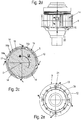
- the gearbox 5 has - see also Fig. 2b or Fig. 4b a transmission outer part 10 which rotates during operation in a direction of rotation U.
- the gear cooling device 9 is placed substantially externally on this rotating gear outer part 10 of the transmission 5 and surrounds it concentrically over part of its axial extent (not where drive belts are provided).
- the axis of rotation to which the terms "radial” and “axial” refer hereinafter, is in Fig. 2c denoted by D and extends perpendicular to the plane of Fig. 2c ,
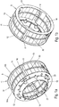
- the gear cooling device 9 is formed as an annular body 11, which is set to the transmission and the outer gear part 10 of the transmission 5 surrounds outside at least partially or even preferably envelops.
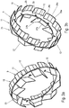
- the ring body 11 has at least one ring 12 - see Fig. 3 - or - see Fig. 1 - Two or more axially spaced rings 12, 13, on which at least one or more louvers 14, 15, 16, 25 are formed, in particular mounted.
- the rings 12, 13 are designed as radially aligned annular discs which are provided on bores 23 on the gear 5 with screws 24 (FIG. Fig. 1a or 2a) or the like. For example, be mounted on an axial portion of the transmission. But there are also other alternative types of attachment to the transmission 5 conceivable.
- louvers 14 are each integrally formed by bending from cut sheet metal strip. These are attached to one ring 12 or to several of the rings 12, 13.
- louvers 14, 15, 16, 25 of the Fig. 1 and the Fig. 3 are configured and aligned so that they lead radially radially outward radially closer to the surface of the transmission 5.
- the louvers 14, 16, 25 act on the one hand as wings that increase the flow of air in the vicinity of the transmission 5 and forward this anyway at least for the greater part due to their geometry from radially outward radially closer to the transmission surface until it returns from there flows.
- the one or more louvers 14, 15, 16, 25 may each be integrally formed or multi-piece. They are on the ring 12 ( Fig. 3 ) or the rings 12, 13 and after Fig. 1 between the rings 12, 13 attached. To Fig. 1 form the louvers 14 and the rings 12, 13 in interaction a kind of shell around the gear 5, here the rotating gear part 10, the inlets 17 and outlets 18 has in several places in the manner to be discussed below.
- Fig. 1 and 2 has the transmission cooling device 9 circumferentially distributed between the two rings 12, 13 one or preferably more - in Fig. 1 four - the louvers 14. These are shaped so as to guide air in each case in an outer blade-like air collecting region 14a at the respective inlet 17 radially inwards towards the outer surface of the gearbox, where the air is passed in a gap 19 between the gear outer surface and a personallysluftleit Scheme 14b in the circumferential direction is until the air in each case in front of a radial portion 14 c, which preferably touches the transmission outer surface or almost touched, is prevented in the circumferential direction on the further flow.
- Fig. 1 and 2 a kind of preferably almost closed shell formed around the gear 5, but at some circumferential positions, the openings or inlets 17 and outlets 18, but dammed up similar to a pitot tube effect air and through the gap 19 between the gear 5 and Case is conducted.
- the louvers 14 may be circumferentially stabilized, for example, with another ring 20 located axially between the rings 12, 13.
- the louvers 14 in particular act in a completely or largely cylindrical transmission area 5a with regard to the outer contour.
- a further - here also conically shaped - louver 15 is provided which is formed as a conical sheet metal ring.
- a conical gap 28 (FIG. Fig. 2b ) is formed between the transmission 5 and the louver 15 with at least one inlet and at least one outlet.
- the louver 15 Toward the ring 12, the louver 15 has one or more windows or recesses 22 as outlets. In this way, air is sucked through the gap 28, which can escape radially outward through the windows or recesses 22 as outlets ( Fig. 2b ).
- This optional air guiding device 15, unlike the air guiding devices 14, 16, 25, also blows the air radially to the here conical surface. It acts in addition cooling in the conical transmission portion 5b and is therefore advantageous.
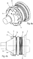
- louvers 16 and 25 are formed at the two axial sides of this ring 12.
- These louvers 16 and 25 each have a plurality on the two sides of the ring 12 circumferentially distributed air baffles 26, 27.
- These air baffles 26, 27 in turn each have at least one more in the circumferential direction or more tangentially oriented portion 26a, 27a and at least one or more adjoining further radially bent portions 26b, c; 27b. In this way, during operation, air is directed further from outside to inside the transmission.
- the air baffles 26 of the louver 16 extend at one end radially to the surface of the rotating gear part 10 zoom ( Fig. 4e ). Thus, a kind of shell is formed again, with the rotation heated by the ambient air substantially only the baffles 26 as a shell.
- the guided to the rotating gear part 10 air accumulates in front of the surface and flows laterally axially, so that the transmission surface is also cooled by the thus forming air flow.
- the louvers 16 are provided to direct air into the more cylindrical transmission portion 5a of the transmission 5 and the louvers 25 to direct air into the more conical transmission portion 5b of the transmission 5. It is air again directed radially from outside to inside the transmission 5, wherein the air axially laterally from the louvers 16, 26 can escape at the outer periphery of the transmission 5 (see Fig. 4a - e ).
Landscapes
- Engineering & Computer Science (AREA)
- General Engineering & Computer Science (AREA)
- Mechanical Engineering (AREA)
- Centrifugal Separators (AREA)
- General Details Of Gearings (AREA)
Applications Claiming Priority (2)
| Application Number | Priority Date | Filing Date | Title |
|---|---|---|---|
| DE102015115720.9A DE102015115720A1 (de) | 2015-09-17 | 2015-09-17 | Antriebsvorrichtung für eine Vollmantel-Schneckenzentrifuge |
| PCT/EP2016/070662 WO2017045929A1 (de) | 2015-09-17 | 2016-09-01 | Kühlvorrichtung für einen antrieb einer vollmantel-schneckenzentrifuge |
Publications (2)
| Publication Number | Publication Date |
|---|---|
| EP3349911A1 EP3349911A1 (de) | 2018-07-25 |
| EP3349911B1 true EP3349911B1 (de) | 2019-11-06 |
Family
ID=56893953
Family Applications (1)
| Application Number | Title | Priority Date | Filing Date |
|---|---|---|---|
| EP16763232.2A Active EP3349911B1 (de) | 2015-09-17 | 2016-09-01 | Kühlvorrichtung für einen antrieb einer vollmantel-schneckenzentrifuge |
Country Status (7)
Families Citing this family (2)
| Publication number | Priority date | Publication date | Assignee | Title |
|---|---|---|---|---|
| USD1015564S1 (en) * | 2018-10-11 | 2024-02-20 | Human Brain Wave S.R.L. | Medical vessel for a specimen |
| CN114483925B (zh) * | 2021-12-24 | 2023-06-30 | 江苏高创风电设备有限公司 | 一种外置风力发电机组齿轮箱用风冷散热系统 |
Family Cites Families (14)
| Publication number | Priority date | Publication date | Assignee | Title |
|---|---|---|---|---|
| DE2849547A1 (de) * | 1978-11-15 | 1980-05-22 | Kloeckner Humboldt Deutz Ag | Schneckenzentrifuge |
| US6589154B2 (en) * | 2001-05-30 | 2003-07-08 | Alfa Laval Inc. | Decanter centrifuge with a gear box mounted on the bowl |
| GB2393142B (en) * | 2002-09-21 | 2004-11-10 | Incentra Ltd | Centrifuge with viscous clutch for decanter drive mechanism |
| DE102006028804A1 (de) | 2006-06-23 | 2007-12-27 | Westfalia Separator Ag | Schneckenzentrifuge mit Antriebsvorrichtung |
| JP5507985B2 (ja) | 2009-12-10 | 2014-05-28 | 住友重機械工業株式会社 | 駆動装置の冷却ファン及びその冷却ファン構造 |
| CN202097039U (zh) * | 2011-05-30 | 2012-01-04 | 江油市丹阳机电设备有限责任公司 | 一种卧螺离心机主轴承冷却装置 |
| DE102011108008A1 (de) * | 2011-07-19 | 2013-01-24 | Harry Gaus | Dekanterzentrifuge |
| CN202191968U (zh) * | 2011-08-31 | 2012-04-18 | 大龙兴创实验仪器(北京)有限公司 | 一种离心机的风冷装置 |
| SE536146C2 (sv) | 2011-11-08 | 2013-05-28 | Scania Cv Ab | Remskiva för generering av kylande luftflöde mot en maskin |
| US8776930B2 (en) * | 2012-02-29 | 2014-07-15 | Arctic Cat Inc. | Fan for drive clutch |
| CN203108669U (zh) * | 2013-03-20 | 2013-08-07 | 向开兴 | 高温离心沉降分离机 |
| DE102014107294B4 (de) * | 2014-05-23 | 2017-02-09 | Andreas Hettich Gmbh & Co. Kg | Zentrifuge |
| DE102014108236A1 (de) | 2014-06-12 | 2015-12-17 | Gea Mechanical Equipment Gmbh | Vollmantel-Schneckenzentrifuge und Verfahren zu deren Betrieb |
| WO2016168439A1 (en) * | 2015-04-17 | 2016-10-20 | Dana Limited | Passive centrifugal hydraulic clamping for high-speed continuously variable planetary operation |
-
2015
- 2015-09-17 DE DE102015115720.9A patent/DE102015115720A1/de not_active Withdrawn
-
2016
- 2016-09-01 WO PCT/EP2016/070662 patent/WO2017045929A1/de active Application Filing
- 2016-09-01 EP EP16763232.2A patent/EP3349911B1/de active Active
- 2016-09-01 CN CN201680053842.0A patent/CN108025319B/zh active Active
- 2016-09-01 US US15/760,896 patent/US11219905B2/en active Active
- 2016-09-01 JP JP2018534003A patent/JP6779297B2/ja active Active
- 2016-09-01 DK DK16763232.2T patent/DK3349911T3/da active
Non-Patent Citations (1)
| Title |
|---|
| None * |
Also Published As
| Publication number | Publication date |
|---|---|
| WO2017045929A1 (de) | 2017-03-23 |
| JP6779297B2 (ja) | 2020-11-04 |
| DE102015115720A1 (de) | 2017-03-23 |
| CN108025319A (zh) | 2018-05-11 |
| JP2018527182A (ja) | 2018-09-20 |
| CN108025319B (zh) | 2020-11-06 |
| DK3349911T3 (da) | 2020-01-27 |
| EP3349911A1 (de) | 2018-07-25 |
| US20180280993A1 (en) | 2018-10-04 |
| US11219905B2 (en) | 2022-01-11 |
Similar Documents
| Publication | Publication Date | Title |
|---|---|---|
| EP3315788A1 (de) | Axiallüfterrad | |
| DE3147404A1 (de) | Zentrifuge | |
| DE102017121739A1 (de) | Ölverteilungssystem mit wenigstens einem ersten drehbar ausgeführten Bereich und einem zweiten Bereich | |
| EP2993094B1 (de) | Hydrodynamischer retarder | |
| DE102007054233B4 (de) | Vorrichtung zum Dispergieren oder Homogenisieren | |
| DE102015011863B4 (de) | Elektrische Maschine | |
| EP2271852B1 (de) | Vorrichtung zur abdichtung einer mit einem flüssigen schmiermittel geschmierten lagerung | |
| EP3349911B1 (de) | Kühlvorrichtung für einen antrieb einer vollmantel-schneckenzentrifuge | |
| EP4381206B1 (de) | Stirnradgetriebe | |
| DE3026517A1 (de) | Brandgasventilator | |
| WO2013010667A1 (de) | Dekanterzentrifuge | |
| EP3670965B1 (de) | Getriebevorrichtung für einen multicopter | |
| EP3542066B1 (de) | Zweiflutige strömungsmaschine | |
| EP3804095B1 (de) | Rotor für eine elektrische maschine, insbesondere eines kraftfahrzeugs, sowie elektrische maschine, insbesondere für ein kraftfahrzeug | |
| DE2216986A1 (de) | Mischvorrichtung zur kontinuierlichen Herstellung einer Paste, einer Creme oder dergleichen | |
| DE102019110996A1 (de) | Vollmantel-Schneckenzentrifuge | |
| DE102013222116A1 (de) | Lüfterkupplung | |
| DE102007056493B3 (de) | Lüfterrad | |
| DE1551178A1 (de) | Stroemungsmaschine | |
| DE102016115557A1 (de) | Zentrifuge mit einer Schälscheibe | |
| DE102023114169A1 (de) | Antriebseinheit | |
| DE102017112581A1 (de) | Hydrodynamische Kupplung | |
| DE102023114464A1 (de) | Antriebsvorrichtung für ein Luftfahrzeug mit einer Mantelvorrichtung zur Luftführung | |
| WO2000024516A1 (de) | Fleischverarbeitungsmaschine mit einer evakuierungseinrichtung | |
| DE1931596A1 (de) | Wirbelstromkupplung |
Legal Events
| Date | Code | Title | Description |
|---|---|---|---|
| STAA | Information on the status of an ep patent application or granted ep patent |
Free format text: STATUS: UNKNOWN |
|
| STAA | Information on the status of an ep patent application or granted ep patent |
Free format text: STATUS: THE INTERNATIONAL PUBLICATION HAS BEEN MADE |
|
| PUAI | Public reference made under article 153(3) epc to a published international application that has entered the european phase |
Free format text: ORIGINAL CODE: 0009012 |
|
| STAA | Information on the status of an ep patent application or granted ep patent |
Free format text: STATUS: REQUEST FOR EXAMINATION WAS MADE |
|
| 17P | Request for examination filed |
Effective date: 20180413 |
|
| AK | Designated contracting states |
Kind code of ref document: A1 Designated state(s): AL AT BE BG CH CY CZ DE DK EE ES FI FR GB GR HR HU IE IS IT LI LT LU LV MC MK MT NL NO PL PT RO RS SE SI SK SM TR |
|
| AX | Request for extension of the european patent |
Extension state: BA ME |
|
| RIN1 | Information on inventor provided before grant (corrected) |
Inventor name: TERHOLSEN, STEFAN Inventor name: KNOBEL, ANDREAS Inventor name: OVERBERG, MARTIN Inventor name: HERMELER, JUERGEN Inventor name: KNOSPE, VOLKER Inventor name: DRIFTSCHROEER, CHRISTIAN |
|
| DAV | Request for validation of the european patent (deleted) | ||
| DAX | Request for extension of the european patent (deleted) | ||
| GRAP | Despatch of communication of intention to grant a patent |
Free format text: ORIGINAL CODE: EPIDOSNIGR1 |
|
| STAA | Information on the status of an ep patent application or granted ep patent |
Free format text: STATUS: GRANT OF PATENT IS INTENDED |
|
| INTG | Intention to grant announced |
Effective date: 20190314 |
|
| GRAS | Grant fee paid |
Free format text: ORIGINAL CODE: EPIDOSNIGR3 |
|
| GRAJ | Information related to disapproval of communication of intention to grant by the applicant or resumption of examination proceedings by the epo deleted |
Free format text: ORIGINAL CODE: EPIDOSDIGR1 |
|
| GRAL | Information related to payment of fee for publishing/printing deleted |
Free format text: ORIGINAL CODE: EPIDOSDIGR3 |
|
| STAA | Information on the status of an ep patent application or granted ep patent |
Free format text: STATUS: REQUEST FOR EXAMINATION WAS MADE |
|
| INTC | Intention to grant announced (deleted) | ||
| GRAR | Information related to intention to grant a patent recorded |
Free format text: ORIGINAL CODE: EPIDOSNIGR71 |
|
| STAA | Information on the status of an ep patent application or granted ep patent |
Free format text: STATUS: GRANT OF PATENT IS INTENDED |
|
| INTG | Intention to grant announced |
Effective date: 20190823 |
|
| GRAA | (expected) grant |
Free format text: ORIGINAL CODE: 0009210 |
|
| STAA | Information on the status of an ep patent application or granted ep patent |
Free format text: STATUS: THE PATENT HAS BEEN GRANTED |
|
| AK | Designated contracting states |
Kind code of ref document: B1 Designated state(s): AL AT BE BG CH CY CZ DE DK EE ES FI FR GB GR HR HU IE IS IT LI LT LU LV MC MK MT NL NO PL PT RO RS SE SI SK SM TR |
|
| REG | Reference to a national code |
Ref country code: GB Ref legal event code: FG4D Free format text: NOT ENGLISH |
|
| REG | Reference to a national code |
Ref country code: CH Ref legal event code: EP Ref country code: AT Ref legal event code: REF Ref document number: 1198037 Country of ref document: AT Kind code of ref document: T Effective date: 20191115 |
|
| REG | Reference to a national code |
Ref country code: IE Ref legal event code: FG4D Free format text: LANGUAGE OF EP DOCUMENT: GERMAN |
|
| REG | Reference to a national code |
Ref country code: DE Ref legal event code: R096 Ref document number: 502016007469 Country of ref document: DE |
|
| REG | Reference to a national code |
Ref country code: DK Ref legal event code: T3 Effective date: 20200122 |
|
| REG | Reference to a national code |
Ref country code: NL Ref legal event code: MP Effective date: 20191106 |
|
| REG | Reference to a national code |
Ref country code: LT Ref legal event code: MG4D |
|
| PG25 | Lapsed in a contracting state [announced via postgrant information from national office to epo] |
Ref country code: FI Free format text: LAPSE BECAUSE OF FAILURE TO SUBMIT A TRANSLATION OF THE DESCRIPTION OR TO PAY THE FEE WITHIN THE PRESCRIBED TIME-LIMIT Effective date: 20191106 Ref country code: BG Free format text: LAPSE BECAUSE OF FAILURE TO SUBMIT A TRANSLATION OF THE DESCRIPTION OR TO PAY THE FEE WITHIN THE PRESCRIBED TIME-LIMIT Effective date: 20200206 Ref country code: GR Free format text: LAPSE BECAUSE OF FAILURE TO SUBMIT A TRANSLATION OF THE DESCRIPTION OR TO PAY THE FEE WITHIN THE PRESCRIBED TIME-LIMIT Effective date: 20200207 Ref country code: PL Free format text: LAPSE BECAUSE OF FAILURE TO SUBMIT A TRANSLATION OF THE DESCRIPTION OR TO PAY THE FEE WITHIN THE PRESCRIBED TIME-LIMIT Effective date: 20191106 Ref country code: NO Free format text: LAPSE BECAUSE OF FAILURE TO SUBMIT A TRANSLATION OF THE DESCRIPTION OR TO PAY THE FEE WITHIN THE PRESCRIBED TIME-LIMIT Effective date: 20200206 Ref country code: PT Free format text: LAPSE BECAUSE OF FAILURE TO SUBMIT A TRANSLATION OF THE DESCRIPTION OR TO PAY THE FEE WITHIN THE PRESCRIBED TIME-LIMIT Effective date: 20200306 Ref country code: LV Free format text: LAPSE BECAUSE OF FAILURE TO SUBMIT A TRANSLATION OF THE DESCRIPTION OR TO PAY THE FEE WITHIN THE PRESCRIBED TIME-LIMIT Effective date: 20191106 Ref country code: SE Free format text: LAPSE BECAUSE OF FAILURE TO SUBMIT A TRANSLATION OF THE DESCRIPTION OR TO PAY THE FEE WITHIN THE PRESCRIBED TIME-LIMIT Effective date: 20191106 Ref country code: LT Free format text: LAPSE BECAUSE OF FAILURE TO SUBMIT A TRANSLATION OF THE DESCRIPTION OR TO PAY THE FEE WITHIN THE PRESCRIBED TIME-LIMIT Effective date: 20191106 Ref country code: NL Free format text: LAPSE BECAUSE OF FAILURE TO SUBMIT A TRANSLATION OF THE DESCRIPTION OR TO PAY THE FEE WITHIN THE PRESCRIBED TIME-LIMIT Effective date: 20191106 |
|
| PG25 | Lapsed in a contracting state [announced via postgrant information from national office to epo] |
Ref country code: IS Free format text: LAPSE BECAUSE OF FAILURE TO SUBMIT A TRANSLATION OF THE DESCRIPTION OR TO PAY THE FEE WITHIN THE PRESCRIBED TIME-LIMIT Effective date: 20200306 Ref country code: RS Free format text: LAPSE BECAUSE OF FAILURE TO SUBMIT A TRANSLATION OF THE DESCRIPTION OR TO PAY THE FEE WITHIN THE PRESCRIBED TIME-LIMIT Effective date: 20191106 Ref country code: HR Free format text: LAPSE BECAUSE OF FAILURE TO SUBMIT A TRANSLATION OF THE DESCRIPTION OR TO PAY THE FEE WITHIN THE PRESCRIBED TIME-LIMIT Effective date: 20191106 |
|
| PG25 | Lapsed in a contracting state [announced via postgrant information from national office to epo] |
Ref country code: AL Free format text: LAPSE BECAUSE OF FAILURE TO SUBMIT A TRANSLATION OF THE DESCRIPTION OR TO PAY THE FEE WITHIN THE PRESCRIBED TIME-LIMIT Effective date: 20191106 |
|
| PG25 | Lapsed in a contracting state [announced via postgrant information from national office to epo] |
Ref country code: ES Free format text: LAPSE BECAUSE OF FAILURE TO SUBMIT A TRANSLATION OF THE DESCRIPTION OR TO PAY THE FEE WITHIN THE PRESCRIBED TIME-LIMIT Effective date: 20191106 Ref country code: EE Free format text: LAPSE BECAUSE OF FAILURE TO SUBMIT A TRANSLATION OF THE DESCRIPTION OR TO PAY THE FEE WITHIN THE PRESCRIBED TIME-LIMIT Effective date: 20191106 Ref country code: RO Free format text: LAPSE BECAUSE OF FAILURE TO SUBMIT A TRANSLATION OF THE DESCRIPTION OR TO PAY THE FEE WITHIN THE PRESCRIBED TIME-LIMIT Effective date: 20191106 Ref country code: CZ Free format text: LAPSE BECAUSE OF FAILURE TO SUBMIT A TRANSLATION OF THE DESCRIPTION OR TO PAY THE FEE WITHIN THE PRESCRIBED TIME-LIMIT Effective date: 20191106 |
|
| REG | Reference to a national code |
Ref country code: DE Ref legal event code: R097 Ref document number: 502016007469 Country of ref document: DE |
|
| PG25 | Lapsed in a contracting state [announced via postgrant information from national office to epo] |
Ref country code: SM Free format text: LAPSE BECAUSE OF FAILURE TO SUBMIT A TRANSLATION OF THE DESCRIPTION OR TO PAY THE FEE WITHIN THE PRESCRIBED TIME-LIMIT Effective date: 20191106 Ref country code: SK Free format text: LAPSE BECAUSE OF FAILURE TO SUBMIT A TRANSLATION OF THE DESCRIPTION OR TO PAY THE FEE WITHIN THE PRESCRIBED TIME-LIMIT Effective date: 20191106 |
|
| PLBE | No opposition filed within time limit |
Free format text: ORIGINAL CODE: 0009261 |
|
| STAA | Information on the status of an ep patent application or granted ep patent |
Free format text: STATUS: NO OPPOSITION FILED WITHIN TIME LIMIT |
|
| 26N | No opposition filed |
Effective date: 20200807 |
|
| PG25 | Lapsed in a contracting state [announced via postgrant information from national office to epo] |
Ref country code: SI Free format text: LAPSE BECAUSE OF FAILURE TO SUBMIT A TRANSLATION OF THE DESCRIPTION OR TO PAY THE FEE WITHIN THE PRESCRIBED TIME-LIMIT Effective date: 20191106 |
|
| REG | Reference to a national code |
Ref country code: CH Ref legal event code: PL |
|
| GBPC | Gb: european patent ceased through non-payment of renewal fee |
Effective date: 20200901 |
|
| REG | Reference to a national code |
Ref country code: BE Ref legal event code: MM Effective date: 20200930 |
|
| PG25 | Lapsed in a contracting state [announced via postgrant information from national office to epo] |
Ref country code: LU Free format text: LAPSE BECAUSE OF NON-PAYMENT OF DUE FEES Effective date: 20200901 |
|
| PG25 | Lapsed in a contracting state [announced via postgrant information from national office to epo] |
Ref country code: BE Free format text: LAPSE BECAUSE OF NON-PAYMENT OF DUE FEES Effective date: 20200930 Ref country code: CH Free format text: LAPSE BECAUSE OF NON-PAYMENT OF DUE FEES Effective date: 20200930 Ref country code: GB Free format text: LAPSE BECAUSE OF NON-PAYMENT OF DUE FEES Effective date: 20200901 Ref country code: IE Free format text: LAPSE BECAUSE OF NON-PAYMENT OF DUE FEES Effective date: 20200901 Ref country code: LI Free format text: LAPSE BECAUSE OF NON-PAYMENT OF DUE FEES Effective date: 20200930 |
|
| PG25 | Lapsed in a contracting state [announced via postgrant information from national office to epo] |
Ref country code: MT Free format text: LAPSE BECAUSE OF FAILURE TO SUBMIT A TRANSLATION OF THE DESCRIPTION OR TO PAY THE FEE WITHIN THE PRESCRIBED TIME-LIMIT Effective date: 20191106 Ref country code: CY Free format text: LAPSE BECAUSE OF FAILURE TO SUBMIT A TRANSLATION OF THE DESCRIPTION OR TO PAY THE FEE WITHIN THE PRESCRIBED TIME-LIMIT Effective date: 20191106 |
|
| PG25 | Lapsed in a contracting state [announced via postgrant information from national office to epo] |
Ref country code: MK Free format text: LAPSE BECAUSE OF FAILURE TO SUBMIT A TRANSLATION OF THE DESCRIPTION OR TO PAY THE FEE WITHIN THE PRESCRIBED TIME-LIMIT Effective date: 20191106 Ref country code: MC Free format text: LAPSE BECAUSE OF FAILURE TO SUBMIT A TRANSLATION OF THE DESCRIPTION OR TO PAY THE FEE WITHIN THE PRESCRIBED TIME-LIMIT Effective date: 20191106 |
|
| REG | Reference to a national code |
Ref country code: AT Ref legal event code: MM01 Ref document number: 1198037 Country of ref document: AT Kind code of ref document: T Effective date: 20210901 |
|
| PG25 | Lapsed in a contracting state [announced via postgrant information from national office to epo] |
Ref country code: AT Free format text: LAPSE BECAUSE OF NON-PAYMENT OF DUE FEES Effective date: 20210901 |
|
| P01 | Opt-out of the competence of the unified patent court (upc) registered |
Effective date: 20230415 |
|
| PGFP | Annual fee paid to national office [announced via postgrant information from national office to epo] |
Ref country code: DE Payment date: 20240926 Year of fee payment: 9 |
|
| PGFP | Annual fee paid to national office [announced via postgrant information from national office to epo] |
Ref country code: DK Payment date: 20240923 Year of fee payment: 9 |
|
| PGFP | Annual fee paid to national office [announced via postgrant information from national office to epo] |
Ref country code: FR Payment date: 20240924 Year of fee payment: 9 |
|
| PGFP | Annual fee paid to national office [announced via postgrant information from national office to epo] |
Ref country code: IT Payment date: 20240926 Year of fee payment: 9 |
|
| PGFP | Annual fee paid to national office [announced via postgrant information from national office to epo] |
Ref country code: TR Payment date: 20240826 Year of fee payment: 9 |