EP3349897B1 - Device and method for fluid separation by density gradient centrifugation - Google Patents
Device and method for fluid separation by density gradient centrifugation Download PDFInfo
- Publication number
- EP3349897B1 EP3349897B1 EP16791676.6A EP16791676A EP3349897B1 EP 3349897 B1 EP3349897 B1 EP 3349897B1 EP 16791676 A EP16791676 A EP 16791676A EP 3349897 B1 EP3349897 B1 EP 3349897B1
- Authority
- EP
- European Patent Office
- Prior art keywords
- container
- partition
- separation
- centrifugation
- density
- Prior art date
- Legal status (The legal status is an assumption and is not a legal conclusion. Google has not performed a legal analysis and makes no representation as to the accuracy of the status listed.)
- Active
Links
- 238000000926 separation method Methods 0.000 title claims description 56
- 238000000034 method Methods 0.000 title claims description 27
- 238000000432 density-gradient centrifugation Methods 0.000 title claims description 10
- 239000012530 fluid Substances 0.000 title description 22
- 238000005192 partition Methods 0.000 claims description 69
- 239000007788 liquid Substances 0.000 claims description 52
- 238000005119 centrifugation Methods 0.000 claims description 42
- 210000004369 blood Anatomy 0.000 claims description 29
- 239000008280 blood Substances 0.000 claims description 29
- 238000012360 testing method Methods 0.000 claims description 16
- 210000003743 erythrocyte Anatomy 0.000 claims description 13
- 210000000265 leukocyte Anatomy 0.000 claims description 11
- 239000013060 biological fluid Substances 0.000 claims description 9
- 239000000523 sample Substances 0.000 claims description 9
- 210000004027 cell Anatomy 0.000 claims description 8
- 238000011049 filling Methods 0.000 claims description 6
- 239000000725 suspension Substances 0.000 claims description 5
- 239000012472 biological sample Substances 0.000 claims description 4
- 238000004458 analytical method Methods 0.000 claims description 3
- 239000012503 blood component Substances 0.000 claims description 3
- 210000001772 blood platelet Anatomy 0.000 claims description 3
- 241000233866 Fungi Species 0.000 claims description 2
- 241000700605 Viruses Species 0.000 claims description 2
- 210000002798 bone marrow cell Anatomy 0.000 claims description 2
- 210000003763 chloroplast Anatomy 0.000 claims description 2
- 210000002889 endothelial cell Anatomy 0.000 claims description 2
- 210000001808 exosome Anatomy 0.000 claims description 2
- 239000012634 fragment Substances 0.000 claims description 2
- 230000008014 freezing Effects 0.000 claims description 2
- 238000007710 freezing Methods 0.000 claims description 2
- 210000003714 granulocyte Anatomy 0.000 claims description 2
- 210000004698 lymphocyte Anatomy 0.000 claims description 2
- 210000003593 megakaryocyte Anatomy 0.000 claims description 2
- 239000011859 microparticle Substances 0.000 claims description 2
- 210000003470 mitochondria Anatomy 0.000 claims description 2
- 210000002569 neuron Anatomy 0.000 claims description 2
- 210000003924 normoblast Anatomy 0.000 claims description 2
- 210000004940 nucleus Anatomy 0.000 claims description 2
- 210000003463 organelle Anatomy 0.000 claims description 2
- 210000003819 peripheral blood mononuclear cell Anatomy 0.000 description 10
- 239000000243 solution Substances 0.000 description 9
- 210000000224 granular leucocyte Anatomy 0.000 description 8
- 238000007373 indentation Methods 0.000 description 8
- 239000000463 material Substances 0.000 description 7
- KCXVZYZYPLLWCC-UHFFFAOYSA-N EDTA Chemical compound OC(=O)CN(CC(O)=O)CCN(CC(O)=O)CC(O)=O KCXVZYZYPLLWCC-UHFFFAOYSA-N 0.000 description 5
- 239000000203 mixture Substances 0.000 description 5
- 210000002381 plasma Anatomy 0.000 description 5
- 210000000601 blood cell Anatomy 0.000 description 3
- 210000001124 body fluid Anatomy 0.000 description 3
- 239000010839 body fluid Substances 0.000 description 3
- 238000002156 mixing Methods 0.000 description 3
- 239000013049 sediment Substances 0.000 description 3
- 238000004062 sedimentation Methods 0.000 description 3
- 229920001917 Ficoll Polymers 0.000 description 2
- 230000004888 barrier function Effects 0.000 description 2
- 239000012620 biological material Substances 0.000 description 2
- 239000000306 component Substances 0.000 description 2
- 238000010908 decantation Methods 0.000 description 2
- 230000000694 effects Effects 0.000 description 2
- 238000002474 experimental method Methods 0.000 description 2
- 230000005484 gravity Effects 0.000 description 2
- 238000000746 purification Methods 0.000 description 2
- 239000000126 substance Substances 0.000 description 2
- 239000012224 working solution Substances 0.000 description 2
- 108091032973 (ribonucleotides)n+m Proteins 0.000 description 1
- 206010006187 Breast cancer Diseases 0.000 description 1
- 208000026310 Breast neoplasm Diseases 0.000 description 1
- 229920002307 Dextran Polymers 0.000 description 1
- 108010010803 Gelatin Proteins 0.000 description 1
- 241001465754 Metazoa Species 0.000 description 1
- 108020005196 Mitochondrial DNA Proteins 0.000 description 1
- 108091093105 Nuclear DNA Proteins 0.000 description 1
- 108010089610 Nuclear Proteins Proteins 0.000 description 1
- 230000001133 acceleration Effects 0.000 description 1
- 238000013019 agitation Methods 0.000 description 1
- 239000000538 analytical sample Substances 0.000 description 1
- 230000004071 biological effect Effects 0.000 description 1
- 230000006727 cell loss Effects 0.000 description 1
- 150000001875 compounds Chemical class 0.000 description 1
- 238000010276 construction Methods 0.000 description 1
- 230000007423 decrease Effects 0.000 description 1
- 239000006185 dispersion Substances 0.000 description 1
- -1 e.g. Substances 0.000 description 1
- 238000001914 filtration Methods 0.000 description 1
- 239000012847 fine chemical Substances 0.000 description 1
- 238000000684 flow cytometry Methods 0.000 description 1
- 238000005194 fractionation Methods 0.000 description 1
- 229920000159 gelatin Polymers 0.000 description 1
- 239000008273 gelatin Substances 0.000 description 1
- 235000019322 gelatine Nutrition 0.000 description 1
- 235000011852 gelatine desserts Nutrition 0.000 description 1
- 230000016507 interphase Effects 0.000 description 1
- 238000002955 isolation Methods 0.000 description 1
- 210000003622 mature neutrocyte Anatomy 0.000 description 1
- GGGDNPWHMNJRFN-UHFFFAOYSA-N metrizoic acid Chemical compound CC(=O)N(C)C1=C(I)C(NC(C)=O)=C(I)C(C(O)=O)=C1I GGGDNPWHMNJRFN-UHFFFAOYSA-N 0.000 description 1
- 108091070501 miRNA Proteins 0.000 description 1
- 239000002679 microRNA Substances 0.000 description 1
- 210000005087 mononuclear cell Anatomy 0.000 description 1
- 230000007935 neutral effect Effects 0.000 description 1
- 230000002093 peripheral effect Effects 0.000 description 1
- 230000000704 physical effect Effects 0.000 description 1
- 229920000642 polymer Polymers 0.000 description 1
- 238000002360 preparation method Methods 0.000 description 1
- 102000004169 proteins and genes Human genes 0.000 description 1
- 229950000550 sodium metrizoate Drugs 0.000 description 1
- 230000001225 therapeutic effect Effects 0.000 description 1
- 210000004881 tumor cell Anatomy 0.000 description 1
Images


Classifications
-
- B—PERFORMING OPERATIONS; TRANSPORTING
- B01—PHYSICAL OR CHEMICAL PROCESSES OR APPARATUS IN GENERAL
- B01L—CHEMICAL OR PHYSICAL LABORATORY APPARATUS FOR GENERAL USE
- B01L3/00—Containers or dishes for laboratory use, e.g. laboratory glassware; Droppers
- B01L3/50—Containers for the purpose of retaining a material to be analysed, e.g. test tubes
- B01L3/502—Containers for the purpose of retaining a material to be analysed, e.g. test tubes with fluid transport, e.g. in multi-compartment structures
- B01L3/5021—Test tubes specially adapted for centrifugation purposes
-
- B—PERFORMING OPERATIONS; TRANSPORTING
- B01—PHYSICAL OR CHEMICAL PROCESSES OR APPARATUS IN GENERAL
- B01L—CHEMICAL OR PHYSICAL LABORATORY APPARATUS FOR GENERAL USE
- B01L2200/00—Solutions for specific problems relating to chemical or physical laboratory apparatus
- B01L2200/16—Reagents, handling or storing thereof
-
- B—PERFORMING OPERATIONS; TRANSPORTING
- B01—PHYSICAL OR CHEMICAL PROCESSES OR APPARATUS IN GENERAL
- B01L—CHEMICAL OR PHYSICAL LABORATORY APPARATUS FOR GENERAL USE
- B01L2300/00—Additional constructional details
- B01L2300/06—Auxiliary integrated devices, integrated components
- B01L2300/0609—Holders integrated in container to position an object
-
- B—PERFORMING OPERATIONS; TRANSPORTING
- B01—PHYSICAL OR CHEMICAL PROCESSES OR APPARATUS IN GENERAL
- B01L—CHEMICAL OR PHYSICAL LABORATORY APPARATUS FOR GENERAL USE
- B01L2300/00—Additional constructional details
- B01L2300/08—Geometry, shape and general structure
- B01L2300/0861—Configuration of multiple channels and/or chambers in a single devices
- B01L2300/087—Multiple sequential chambers
-
- B—PERFORMING OPERATIONS; TRANSPORTING
- B01—PHYSICAL OR CHEMICAL PROCESSES OR APPARATUS IN GENERAL
- B01L—CHEMICAL OR PHYSICAL LABORATORY APPARATUS FOR GENERAL USE
- B01L2400/00—Moving or stopping fluids
- B01L2400/06—Valves, specific forms thereof
- B01L2400/0633—Valves, specific forms thereof with moving parts
- B01L2400/0644—Valves, specific forms thereof with moving parts rotary valves
Definitions
- the invention relates to a centrifugation container with an insert, and a method of fluid separation using a density gradient centrifugation.
- the invention is used in the separation of body fluids, e.g. blood of animals, including humans, for diagnostic purposes.
- the solution which is the subject of the invention belongs to the field of containers for laboratory purposes, and especially to tubes specifically adapted for centrifugation purposes.
- Another aspect of the invention relates to the field of testing or analyzing materials by determining their chemical, physical or biological properties, and particularly includes analyzing liquid biological material, e.g., blood.
- Collection, purification, fractionation and/or fixation of body fluid samples, including blood play an important role, e.g. in medical diagnostics and clinical trials.
- blood samples collected from the patient can be separated into different fractions by centrifugation, filtration or elutriation, and then stored for later use or further testing.
- Separated blood components usually contain fractions of red blood cells, white blood cells, platelets and plasma. Separation of blood into its fractions can be carried out continuously, during blood collection or in the stages following its collection. Separating blood into different components under highly sterile conditions is critical for many therapeutic applications and for clinical research purposes.
- WO8805331 there is a technique known for separating white blood cells (leukocytes) from red blood cells (erythrocytes), which consists of mixing a blood sample with a working solution that aggregates red blood cells and thus increases their sedimentation rate.
- the density of the working separation fluids is selected so that the sedimentation of white blood cells is minimally changed and that the white blood cells do not sediment to the bottom, and as a result could be taken from the upper part of the separated liquid after the red blood cells have sediment to the bottom.
- the blood is layered precisely on the surfaces of separation fluids, after which the red blood cells agglutinate or aggregate under the effect of surface contact with the working separation fluids, as a result of which they sediment to the bottom of that tube.
- separation fluids There are several well-known multi-polymer compounds that agglutinate red blood cells, e.g. FICOLL 400 (Pharmacia Fine Chemicals, Sweden). Blood separation can occur under the influence of gravity or under the influence of centrifugation.
- PBMC peripheral blood mononuclear cell
- PMN polymorphonuclear leukocytes
- one known method is to isolate peripheral blood mononuclear cell (PBMC) based on a centrifugation process, wherein the first stage uses the Isopaque-Ficoll mixture (Nyegaard & Co., Norway) having the sodium metrizoate component, in the next stage, polymorphonuclear neutrophils are isolated using dextran or gelatin, which cause sedimentation of red blood cells.
- Another method uses discontinuous density gradients where two or more working separation fluids are poured in layers on top of each other. The densities are selected so that the (discontinuous) gradient is in the appropriate/required range - adjusted to the density of the separated substances.
- U.S. Patent Application No. US4824560 A discloses methods and means of centrifuging in a tubular container having at least two adjacent chambers that are connected to each other by a narrow, essentially capillary opening.
- the working fluid is placed in the bottom chamber, while the fluid to be separated into fractions is placed in the upper chamber, and there is no need for special precautions to avoid liquid mixing before starting centrifugation.
- This method has several advantages over the manual methods described above, it also has the disadvantage due to the narrow connection of both chambers which constitutes a partial barrier, even during centrifugation, This barrier prevents effective passage of blood cells between the chambers and precludes separation of the blood into fractions.
- Patent application US2014087360 A1 discloses an insert for a centrifuge tube suitable for use in density gradient separation.
- the insert includes a member sized to fit within the tube for dividing the tube into a top portion and a bottom portion.
- the insert has a support extending or depending from the member for positioning the member within the tube. At least two openings are located on the member so that a first opening is closer to a bottom end of the tube relative to a second opening when the insert is positioned in the centrifuge tube.
- Patent US5314074 A discloses layering insert within the vessel that prevents back mixing after density gradient centrifugation.
- the insert is capable of supporting the body of liquid dispersion to be centrifuged under regular gravity condition and enables bi-directional crossflow during centrifugation.
- Patent US5132232 A discloses apparatus for collecting liquid analytical samples for examination, and reproducibly separating them into two or more fractions.
- An apparatus is utilizing a container and a petter, said petter provided with an upper portion which enables attachment to the container, a lower retainer portion including a peripheral aperture, the non-apertured portion of which enables wedge-fit thereof into the container, and a body portion connecting the upper petter portion and lower retainer portion.
- Patent US5648223 A discloses a cell-trap centrifugation tube containing a specific density gradient solution adjusted to a specific density to enrich for breast tumor cells from a cell mixture.
- the tube allows the desired cell population to be collected by decantation after centrifugation to minimize cell loss and maximize efficiency.
- the aim of the solution according to the invention was to obtain a tool for fast and partially automated separation of fluids into fractions of different density, e.g. biological fluids, including blood, which additionally enable the purification, isolation and fixation of biological samples.
- fluids e.g. biological fluids, including blood
- the essence of the invention is a centrifugation container comprising an insert, especially a test tube, for separation of liquids into fractions of the desired density range by density gradient centrifugation, especially liquids constituting suspensions and/or biological fluids, the insert is equipped with a partition suitable for dividing the container's interior into at least two chambers in a vertical arrangement - the upper chamber and the bottom chamber, characterized in that the partition having an opening into which a guide adjoins, on which liquids, especially biological fluid, flow into the bottom chamber of the centrifugation container, and said partition is made of two adjacent surfaces with openings, especially in the shape of flattened discs fitted to the cross-section of the container with a cross-section similar to the circle, the surfaces being movably connected with each other, they can be freely positioned with each other enabling closing of the opening lumen.
- the guide is spiral, funnel or vertical elements in the shape of an elongated cylinder.
- the upper chamber of centrifugation container has additionally a vertical partition or partitions separating it into sub-chambers, each of the sub-chambers having an opening.
- the invention also includes a method of separating a fraction with a desired density range from a sample containing fractions of different density, especially from a biological sample, comprising:
- the step (b) is followed by an additional step or steps b) consisting of adding an additional density gradient separation medium, wherein the addition of subsequent media is from the highest to the lowest density.
- step (d) selected fractions of different density from the liquid being separated are subjected to tests and analysis, including the possibility of being fixed, especially by the freezing method.
- the individual fractions of the desired density range contain various blood components, including: leukocytes (lymphocytes and granulocytes), platelets, erythrocytes, bone marrow cells (megakaryocytes, erythroblasts), cells suspended in homogenate including endothelial cells, neurons, fungi, viruses, microparticles including exosomes, cell fragments, cell organelles including nuclei, mitochondria, chloroplasts.
- leukocytes lymphocytes and granulocytes
- platelets erythrocytes
- bone marrow cells megakaryocytes, erythroblasts
- cells suspended in homogenate including endothelial cells, neurons, fungi, viruses, microparticles including exosomes, cell fragments, cell organelles including nuclei, mitochondria, chloroplasts.
- the invention also relates to a kit comprising:
- the tube insert 6 for the centrifugation container consists of a partition 7 in the form of a flat disc tightly adhering to the inner walls of the container 1, and a disc 8 equipped with a full vertical partition 11.
- the insert in this example is placed inside a container 1 constituting a 0.23" diameter centrifugation tube.
- Insert 6 in this example is made of plastic, but could also be made of other materials.
- the insert 6 can also be placed in an additional container that can be attached to the centrifugation container 1, then the insert 6 is outside the container 1.
- the wall of the tube-shaped container 1 forms a guide 12 and widens gradually into the container 1 ( Fig. 4 and 5 ), at the same time the lumen of the tube gradually decreases towards its bottom.
- the inner wall of the container 1 is a guide 12 that allows liquids to flow from the upper chamber 2 to the bottom chamber 3 through the opening 4.
- Liquids - especially liquids that are biological fluids for separation - flow down to the bottom of the container 1 along the guide 12, constituted by container wall, and become arranged in layers on the bottom of the container 1.
- the liquid flow down along the guide 12 prevents agitation of the separation liquids, which could cause errors in the separation of the tested liquids.
- the partition 7 has the shape of a flat disc with a circular cross-section ( Fig. 11a, Fig. 11b ) and is closely fitted in shape to the cross-sectional shape of the container 1, so the diameter on its top side is greater than on the bottom side, and the longitudinal section of the partition 7 is close to a flattened inverted trapezoid.
- the partition 7 divides the container 1 into an upper chamber 2 and a bottom chamber 3.
- the partition in the example has an opening 4 constituting an indentation in the shape similar to a semi-circle.
- the vertical partition 11 may be in the shape of a rectangle that closely adheres to the inner wall of the container 1, then the vertical partition 11 located on the disc 8 divides the upper chamber 2 of the container 1 in the shape of a tube into two sub-chambers 10a, 10b .
- the indentation-shaped openings 5 in the disc 8 are semicircular.
- the liquid flow rate from the upper chamber 2 to the bottom chamber 3 depends on the shape of the openings 4, 5 and their mutual arrangement with respect to each other.
- the indentation-shaped openings 4, 5 with an indentation radius of 0.115" are of the same shape.
- the openings 4, 5 may have different shapes and may differ in shape, but their diameter should be greater than 0.1".
- the container 1 is provided with a lid 9.
- the lid 9 has a gap in which the upper part of the vertical partition 11 of the insert 6 fits and passes through. Such a position of the vertical partition 11 allows changing the position of the disc 8 relative to the partition 7 by turning the protruding part of the partition, and thus the movable part of the lid 9.
- the container 1 and the lid 9 have a thread and form a screw cap.
- the lid 9 may be made of plastic and may have a calibrated turning/twisting scale. Markings on the centrifugation container 1 and lid 9 may be provided to facilitate correct alignment/arrangement of the openings 4, 5 in relation to each other.
- the vertical partition 11 may not adhere to the walls of the container 1, then the vertical partition 11 located on the disc 8 divides the tube into two chambers only - the upper chamber 2 and the bottom chamber 3, and the upper chamber 2 is not divided into additional sub-chambers.
- disc 8 is equipped with one indentation-shaped opening 4, wherein the shape of the disc 8 in another version of the example could be limited to closing the openings 4 in the partition 7.
- the vertical partition 11 may consist of three rectangular elements connected together by longer sides, the sides of which are closely adjacent to the inner wall of the container 1, then the vertical partition 11 located on the disc 8 divides the upper chamber 2 of the container 1 in the shape of a tube into three sub-chambers.
- disc 8 is equipped with three indentations 5, one in each of the sub-chambers.
- the vertical partition 11 may consist of four rectangles connected together, the sides of which are closely adjacent to the inner wall of the container 1, then the vertical partition 11 located on the disc 8 divides the upper chamber 2 of the container 1 in the shape of a tube into four sub-chambers.
- disc 8 is equipped with four indentations 5, one in each of the sub-chambers.
- Insert 6 can also be used in containers 1 with shapes other than the centrifugation tube shown in the embodiment, but these containers must be suitable for centrifugation.
- Fig. 13 and 13a shows another embodiment of the solution according to the invention, in which the insert 6 has a partition 7, which does not have an upper chamber, but allows connection, through a tube 16, to the upper chamber partition in the form of a container (e.g. test tube, pouch) with a medium for separation or with liquid for separation.
- the partition is equipped with a guide 12 in the shape of an elongated cylinder, which is attached to the partition 7 and is located at such a distance from the opening 4 that allows liquid to flow from the upper chamber through the tube 16, then through the opening in the partition and along the guide to the bottom chamber 3.
- the elongated cylinder constituting the guide 12 is of such a length that the test material layers onto the surface of the gradient medium without causing significant disturbances in the separation medium.
- Fig. 14 and 14a shows another embodiment of the solution according to the invention, in which the insert 6 has a partition 7, equipped with a guide 12 in the shape of 8 elongated cylinders, which are attached to the partition 7 and are at a distance from the opening 4 allowing liquid to flow from the upper chamber through the opening in the partition following the guide to the bottom chamber 3.
- the elongated cylinders constituting the guide 12 are of such a length that the test material layers onto the surface of the gradient centrifuging medium without causing significant disturbances of the separation medium.
- Fig. 15 and 15a show yet another example of the solution according to the invention, in which the insert 6 has a partition 7 equipped with a spiral-shaped guide 12.
- the spiral length should be such that the test material layers onto the surface of the gradient centrifuging medium without causing significant disturbances in the separation medium.
- Fig. 16, 16a and 16b show yet another example of the solution according to the invention, in which the insert 6 has a partition 7 equipped with a funnel-shaped guide 12. At the same time, openings 4 in the partition 7 direct liquids from the upper chamber so that they flow down along the outer surface of the funnel to the bottom of the chamber 3. Similarly, to example 2, the spiral length should be such that the test material layers onto the surface of the gradient centrifuging medium without causing significant disturbances in the separation medium.
- the method of separating the fraction with the desired density range from a sample containing fractions of different density according to the invention can be carried out in such a way that in different sub-chambers 10a, 10b of upper chamber 2, there are two different separation media placed in a density gradient, the first medium has a density of 1.119 g/mL, the second medium has a density of 1.077 g/mL (Histopaque 1.119 and Histopaque 1.077 from Sigma Aldrich, respectively), with the openings 4,5 constituting indentations - of the partition 7 and disc 8, respectively - not overlapping when remaining in the closed position.
- the indentations 4, 5 overlap enough to allow the medium to flow from the upper chamber 2 to the bottom chamber 3.
- the liquids flow along the inner wall of the container 1 what constitutes the guide 12.
- the position of the openings 4,5 constituting an indentation in the partition 7 and the disc 8 from the example is adjacent to the the wall of the container 1 what constitutes the guide 12.
- the media are added in order from highest to lowest density, and a interphase is formed between the media of different density.
- a liquid or mixture intended for separation into fractions of different density under the influence of centrifugation, e.g. native or diluted blood, is added to one of the empty sub-chambers 10 with a closed flow between the upper chamber 2 and the bottom chamber 3.
- the size of the clearance formed by the openings 4, 5 being cutouts of the partition 7 and the disc 8, respectively, can be controlled by adjusting the mutual position of the partition 7 and the disc 8. Slowly twisting the upper part of the insert 11, and thus the disc 8, gradually increases the fluid flow rate until the assumed liquid flow velocity between the chambers 2, 3 is achieved. By adjusting the amount of mutual overlap between the opening 4 and the opening 5, the liquid flow can be controlled to create a continuous laminar flow along the wall 12 of the centrifugation container 1.
- the construction of the partition 7 and disc 8 according to the invention ensures very smooth down flow of fluid from the upper chamber 2 into the bottom chamber 3 of the centrifugation container 1 in such a way that the interface between liquids is intact and the subsequent liquid poured from the upper chamber 2 does not mix with the liquid present in bottom chamber 3.
- the test sample in the form of blood is added, it is also possible to use different types of fluids for separation, including native or diluted biological samples.
- the blood was first placed in the chamber 10a, and then after turning the disc 8 of the insert 6 in such a way that the opening 4 of the partition 7 matches at least in part with the corresponding opening 5 of the disc 8 of the insert 6, and allows blood to flow along the wall 12 of the container 1 from the sub-chamber 10a to the bottom chamber 3 and to layer on the surface of separation media placed there previously. Due to the structure of the insert 6, it is not necessary for the biological specimen to be placed in container 1 with extreme precision and care.
- the blood in the bottom chamber 3 of the container 1 is then centrifuged according to methods generally known in the art.
- centrifugation two-way fluid flow occurs within different compartments formed by separation fluids of different density in the bottom chamber 3, and a continuous density gradient is formed at the end of centrifugation, with red blood cells settling on the bottom forming the lowest-located layer, the higher layer is a liquid with a density of 1.119 g/mL, the next layer located above is white blood cells with segmented nuclei, above is a layer formed by liquid with a density of 1.077 g/mL, and a layer of white mononuclear cells above that, finally the plasma is located above them as the highest layer.
- each of the cell layers/or liquids can be removed by aspiration using a pipette or decantation.
- the insert and method of the invention is used, for example, to separate a desired subset of blood cells.
- ten blood samples were collected from healthy volunteers (20 mL of venous blood) into commercially available ethylenediaminetetraacetic acid (EDTA) tubes (EDTA tube, Becton Dickinson).
- EDTA ethylenediaminetetraacetic acid
- the volume of the centrifugation tube 1 constituting the invention was 50 mL
- two separation media of different density Histopaque 1.119 and Histopaque 1.077 Sigma Aldrich
- the separation media used had a neutral pH, were isotonic to body fluids, the first separation medium had a density of 1.119 g/mL, while the second had a density of 1.077 g/mL.
- PBMC peripheral blood mononuclear cells
- PMN polymorphonuclear leukocytes
- red blood cells The purity of the PBMC and PMN fractions was confirmed by flow cytometry. The purity of PBMC and PMN in their fractions was 95% and 92%, respectively. PBMC and PMN cells were not detectable in the plasma fraction. Isolated plasma, PBMC and PMN were suitable for further analysis, including but not limited to: RNA, micro-RNA, mitochondrial DNA, nuclear DNA, protein and cell phenotyping.
Description
- The invention relates to a centrifugation container with an insert, and a method of fluid separation using a density gradient centrifugation. In particular, the invention is used in the separation of body fluids, e.g. blood of animals, including humans, for diagnostic purposes. The solution which is the subject of the invention belongs to the field of containers for laboratory purposes, and especially to tubes specifically adapted for centrifugation purposes. Another aspect of the invention relates to the field of testing or analyzing materials by determining their chemical, physical or biological properties, and particularly includes analyzing liquid biological material, e.g., blood.
- Collection, purification, fractionation and/or fixation of body fluid samples, including blood, play an important role, e.g. in medical diagnostics and clinical trials. For conventional systems and methods for collecting blood samples on a large scale, blood samples collected from the patient can be separated into different fractions by centrifugation, filtration or elutriation, and then stored for later use or further testing. Separated blood components usually contain fractions of red blood cells, white blood cells, platelets and plasma. Separation of blood into its fractions can be carried out continuously, during blood collection or in the stages following its collection. Separating blood into different components under highly sterile conditions is critical for many therapeutic applications and for clinical research purposes.
- There are many methods for separating blood into its fractions. The methods known in the state of the art require using state-of-the-art specialized medical/research devices and highly qualified personnel for their proper operation.
- From International Patent Application No.
WO8805331 - In another technique, in which the working solution that aggregates red blood cells is not mixed with blood, the blood is layered precisely on the surfaces of separation fluids, after which the red blood cells agglutinate or aggregate under the effect of surface contact with the working separation fluids, as a result of which they sediment to the bottom of that tube. There are several well-known multi-polymer compounds that agglutinate red blood cells, e.g. FICOLL 400 (Pharmacia Fine Chemicals, Sweden). Blood separation can occur under the influence of gravity or under the influence of centrifugation. Most white blood cells remain at the phase boundary, but these previously developed systems are not effective in separating white blood cells into subpopulations, i.e., into peripheral blood mononuclear cell (PBMC) and polymorphonuclear leukocytes (PMN) populations. In particular, there is an ongoing search for a single-stage method that uses a density separation medium that would enable separation of whole blood cells into subpopulations.
- To perform the aforementioned separation of white blood cells into subpopulations, one known method is to isolate peripheral blood mononuclear cell (PBMC) based on a centrifugation process, wherein the first stage uses the Isopaque-Ficoll mixture (Nyegaard & Co., Norway) having the sodium metrizoate component, in the next stage, polymorphonuclear neutrophils are isolated using dextran or gelatin, which cause sedimentation of red blood cells. Another method uses discontinuous density gradients where two or more working separation fluids are poured in layers on top of each other. The densities are selected so that the (discontinuous) gradient is in the appropriate/required range - adjusted to the density of the separated substances.
- On the other hand, U.S. Patent Application No.
US4824560 A discloses methods and means of centrifuging in a tubular container having at least two adjacent chambers that are connected to each other by a narrow, essentially capillary opening. For operation, the working fluid is placed in the bottom chamber, while the fluid to be separated into fractions is placed in the upper chamber, and there is no need for special precautions to avoid liquid mixing before starting centrifugation. This method has several advantages over the manual methods described above, it also has the disadvantage due to the narrow connection of both chambers which constitutes a partial barrier, even during centrifugation, This barrier prevents effective passage of blood cells between the chambers and precludes separation of the blood into fractions. - Patent application
US2014087360 A1 discloses an insert for a centrifuge tube suitable for use in density gradient separation. The insert includes a member sized to fit within the tube for dividing the tube into a top portion and a bottom portion. Optionally the insert has a support extending or depending from the member for positioning the member within the tube. At least two openings are located on the member so that a first opening is closer to a bottom end of the tube relative to a second opening when the insert is positioned in the centrifuge tube. - Patent
US5314074 A discloses layering insert within the vessel that prevents back mixing after density gradient centrifugation. The insert is capable of supporting the body of liquid dispersion to be centrifuged under regular gravity condition and enables bi-directional crossflow during centrifugation. - Patent
US5132232 A discloses apparatus for collecting liquid analytical samples for examination, and reproducibly separating them into two or more fractions. An apparatus is utilizing a container and a petter, said petter provided with an upper portion which enables attachment to the container, a lower retainer portion including a peripheral aperture, the non-apertured portion of which enables wedge-fit thereof into the container, and a body portion connecting the upper petter portion and lower retainer portion. - Patent
US5648223 A discloses a cell-trap centrifugation tube containing a specific density gradient solution adjusted to a specific density to enrich for breast tumor cells from a cell mixture. The tube allows the desired cell population to be collected by decantation after centrifugation to minimize cell loss and maximize efficiency. - The problem arising in the manual separation methods described above is the preparation of the sample for this process, and in particular in layering of poured liquids used for different density separation and the material being tested, e.g. blood. It is important that fluids do not mix with each other and that interface is established between fluids of different densities. To achieve this state, various techniques and skills have been developed that allow for the proper layering of separation fluids and blood, which are most often carefully pipetted into a container for further separation into fractions using density gradient centrifugation. Unfortunately, these procedures are cumbersome, difficult to perform, introduce the possibility of uncontrolled human errors, and additionally require highly qualified personnel, which is associated with high operating costs, reduces the repeatability of the procedure and precludes large-scale separation/division.
- The aim of the solution according to the invention was to obtain a tool for fast and partially automated separation of fluids into fractions of different density, e.g. biological fluids, including blood, which additionally enable the purification, isolation and fixation of biological samples.
- Within the description of the invention and the claims, the following terms shall be understood in accordance with the following definitions:
- the "container" is any liquid storage container that is adapted to centrifugation, e.g. centrifugation tubes,
- the "guide" is an element of the insert that directs liquid flow from the upper chamber to the bottom chamber through the opening in the partition, the guide should be of such a size that enables the test liquid to layer on the separation medium at the bottom of the container. The guide, in accordance with foregoing definition, may be the container wall or a different structure inside the container e.g. spiral, elongated sleeve, etc.
- The essence of the invention is a centrifugation container comprising an insert, especially a test tube, for separation of liquids into fractions of the desired density range by density gradient centrifugation, especially liquids constituting suspensions and/or biological fluids, the insert is equipped with a partition suitable for dividing the container's interior into at least two chambers in a vertical arrangement - the upper chamber and the bottom chamber, characterized in that the partition having an opening into which a guide adjoins, on which liquids, especially biological fluid, flow into the bottom chamber of the centrifugation container, and said partition is made of two adjacent surfaces with openings, especially in the shape of flattened discs fitted to the cross-section of the container with a cross-section similar to the circle, the surfaces being movably connected with each other, they can be freely positioned with each other enabling closing of the opening lumen.
- Preferably, the guide is spiral, funnel or vertical elements in the shape of an elongated cylinder.
- Preferably, the upper chamber of centrifugation container has additionally a vertical partition or partitions separating it into sub-chambers, each of the sub-chambers having an opening.
- The invention also includes a method of separating a fraction with a desired density range from a sample containing fractions of different density, especially from a biological sample, comprising:
- a) providing a centrifugation container with an insert for a centrifugation container, especially a test tube, for the separation of liquids into fractions of the desired density range by density gradient centrifugation, especially liquids constituting suspensions or biological fluids,
- b) filling the bottom chamber of the container with a medium for separation on a density gradient or filling the top chamber of the container with this medium, which then flows through the opening in the partition along the guide to the bottom chamber;
- c) pouring liquid for separation containing fractions of different density to the bottom chamber by filling the upper chamber or at least one sub-chamber or attaching the upper chamber to the partition, so that the liquid can flow through the opening in the partition on the guide and layer on the surface of the separation media in bottom chamber;
- d) centrifugation of the container until the test sample is separated into fractions of different density.
- Preferably, the step (b) is followed by an additional step or steps b) consisting of adding an additional density gradient separation medium, wherein the addition of subsequent media is from the highest to the lowest density.
- It is equally advantageous if, after step (d), selected fractions of different density from the liquid being separated are subjected to tests and analysis, including the possibility of being fixed, especially by the freezing method.
- Preferably, when the fraction is separated from the blood liquid, the individual fractions of the desired density range contain various blood components, including: leukocytes (lymphocytes and granulocytes), platelets, erythrocytes, bone marrow cells (megakaryocytes, erythroblasts), cells suspended in homogenate including endothelial cells, neurons, fungi, viruses, microparticles including exosomes, cell fragments, cell organelles including nuclei, mitochondria, chloroplasts.
- The invention also relates to a kit comprising:
- a) insert (6) for the container (1) for centrifugation, in particular the tube, for the separation of liquids into fractions of the desired density range by density gradient centrifugation, especially liquids constituting suspensions or biological fluids, this device is equipped with a partition (7) dividing the inside of the container (1) into the upper chamber (2) and the bottom chamber (3), the partition (7) having an opening (4), and at the opening there is a guide (12) on which fluids flow, especially separated fluid, into the bottom chamber (3) of the container (1) for centrifugation,
- b) at least one density gradient separation medium.
- For a better understanding, the invention is illustrated in the embodiment illustrated in the drawing which is not a limitation of the protection applied for, in which:
-
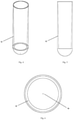
Fig. 1 illustrates a container in the shape of a centrifugation tube with an insert, intended for collecting liquids, in particular biological material, and then for its separation, which - according to the invention - allows layered arrangement of liquids placed in the container before centrifugation; -
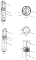
Fig. 2 and 3 illustrate a longitudinal section and a side view of a centrifugation tube container, respectively, in which, for a better understanding of the essence of the invention, the disc and the partition of the insert are spaced apart; -
Fig. 4 and 5 illustrate, the side view and longitudinal section of the tube-shaped container, respectively, with a visible narrowing tube lumen as the wall thickness increases, -
Fig. 6 illustrates a cross section through a tube-shaped container in an example without a vertical partition, but with an air channel visible, -
Fig. 7a and 7b illustrate a side view and cross-section of the upper part of the insert in the form of a disc with an incomplete partition, respectively. -
Fig. 8a and 8b illustrate a side view and cross-section of the upper part of the insert in the form of a disc with a rectangular partition, respectively. -
Fig. 9a and 9b illustrate, a side view and cross-section of the upper part of the insert in the form of a disc with a partition in the shape of three rectangles, respectively. -
Fig. 10a and 10b illustrate, a side view and cross-section of the upper part of the insert in the form of a disc with a partition in the shape of two cross intersecting rectangles, respectively. -
Fig. 11a and 11b illustrate, a cross section and a side view of a disc-shaped partition with a notch, respectively. -
Fig. 12 illustrates one embodiment of the solution of the invention in which the insert is placed on a centrifugation container, -
Fig. 13 and 13a illustrates the insert, a side and top cross-section adapted for connecting the upper chamber equipped with a guide in the shape of an elongated cylinder, respectively. -
Fig. 14 and 14 a illustrates the insert, a cross-section from the side and top, equipped with a guide in the form of eight elongated cylinders, respectively. -
Fig. 15 and 15a illustrate the insert, a side and top cross section equipped with a spiral-shaped guide, respectively. -
Fig. 16, 16a and 16b illustrate the insert cross-section from the side and top view, and enlarged guide, equipped with a funnel-shaped guide, respectively. - As shown in
Fig. 1 , in the first embodiment the tube insert 6 for the centrifugation container consists of apartition 7 in the form of a flat disc tightly adhering to the inner walls of thecontainer 1, and adisc 8 equipped with a fullvertical partition 11. The insert in this example is placed inside acontainer 1 constituting a 0.23" diameter centrifugation tube. Insert 6 in this example is made of plastic, but could also be made of other materials. As shown inFig. 12 , the insert 6 can also be placed in an additional container that can be attached to thecentrifugation container 1, then the insert 6 is outside thecontainer 1. - The wall of the tube-shaped
container 1 forms aguide 12 and widens gradually into the container 1 (Fig. 4 and 5 ), at the same time the lumen of the tube gradually decreases towards its bottom. In this embodiment, the inner wall of thecontainer 1 is aguide 12 that allows liquids to flow from theupper chamber 2 to thebottom chamber 3 through theopening 4. Liquids - especially liquids that are biological fluids for separation - flow down to the bottom of thecontainer 1 along theguide 12, constituted by container wall, and become arranged in layers on the bottom of thecontainer 1. The liquid flow down along theguide 12 prevents agitation of the separation liquids, which could cause errors in the separation of the tested liquids. - In this example, the
partition 7 has the shape of a flat disc with a circular cross-section (Fig. 11a, Fig. 11b ) and is closely fitted in shape to the cross-sectional shape of thecontainer 1, so the diameter on its top side is greater than on the bottom side, and the longitudinal section of thepartition 7 is close to a flattened inverted trapezoid. Thepartition 7 divides thecontainer 1 into anupper chamber 2 and abottom chamber 3. The partition in the example has anopening 4 constituting an indentation in the shape similar to a semi-circle. - As shown in
Fig. 8a and 8b , thevertical partition 11 may be in the shape of a rectangle that closely adheres to the inner wall of thecontainer 1, then thevertical partition 11 located on thedisc 8 divides theupper chamber 2 of thecontainer 1 in the shape of a tube into twosub-chambers disc 8 formed by thepartition 11, there is oneopening 5 in the shape of a notch that can be closed with thedisc 8. In the embodiment, the indentation-shapedopenings 5 in thedisc 8 are semicircular. In other implementations of the solution according to the invention, it is also possible to usediscs 8 with other shapes ofopenings 5. The liquid flow rate from theupper chamber 2 to thebottom chamber 3 depends on the shape of theopenings - In this example, the indentation-shaped
openings openings partition 7 anddisc 8 arranged in such a way that theopenings upper chamber 2 and thebottom chamber 3 is blocked and proper fluid down flow cannot take place. - In this embodiment, the
container 1 is provided with a lid 9. In one version of the example, the lid 9 has a gap in which the upper part of thevertical partition 11 of the insert 6 fits and passes through. Such a position of thevertical partition 11 allows changing the position of thedisc 8 relative to thepartition 7 by turning the protruding part of the partition, and thus the movable part of the lid 9. Thecontainer 1 and the lid 9 have a thread and form a screw cap. Alternatively, the use of the lid without agap 91, where thevertical partition 11 of the insert is adapted to the length of thecontainer 1 so that, after screwing the lid 9, thevertical partition 11 would tightly adhere to the inner surface of the lid 9. The lid 9 may be made of plastic and may have a calibrated turning/twisting scale. Markings on thecentrifugation container 1 and lid 9 may be provided to facilitate correct alignment/arrangement of theopenings - Alternatively, different shapes and arrangements of the
vertical partition 8 are possible in other versions of the embodiment. As shown inFig. 7a and 7b , thevertical partition 11 may not adhere to the walls of thecontainer 1, then thevertical partition 11 located on thedisc 8 divides the tube into two chambers only - theupper chamber 2 and thebottom chamber 3, and theupper chamber 2 is not divided into additional sub-chambers. In this version,disc 8 is equipped with one indentation-shapedopening 4, wherein the shape of thedisc 8 in another version of the example could be limited to closing theopenings 4 in thepartition 7. - As shown in
Fig. 9a and 9b , thevertical partition 11 may consist of three rectangular elements connected together by longer sides, the sides of which are closely adjacent to the inner wall of thecontainer 1, then thevertical partition 11 located on thedisc 8 divides theupper chamber 2 of thecontainer 1 in the shape of a tube into three sub-chambers. In this version,disc 8 is equipped with threeindentations 5, one in each of the sub-chambers. - As shown in
Fig. 10a and 10b , thevertical partition 11 may consist of four rectangles connected together, the sides of which are closely adjacent to the inner wall of thecontainer 1, then thevertical partition 11 located on thedisc 8 divides theupper chamber 2 of thecontainer 1 in the shape of a tube into four sub-chambers. In this version,disc 8 is equipped with fourindentations 5, one in each of the sub-chambers. - Insert 6 can also be used in
containers 1 with shapes other than the centrifugation tube shown in the embodiment, but these containers must be suitable for centrifugation. -
Fig. 13 and 13a shows another embodiment of the solution according to the invention, in which the insert 6 has apartition 7, which does not have an upper chamber, but allows connection, through a tube 16, to the upper chamber partition in the form of a container (e.g. test tube, pouch) with a medium for separation or with liquid for separation. Next, the partition is equipped with aguide 12 in the shape of an elongated cylinder, which is attached to thepartition 7 and is located at such a distance from theopening 4 that allows liquid to flow from the upper chamber through the tube 16, then through the opening in the partition and along the guide to thebottom chamber 3. In this embodiment, the elongated cylinder constituting theguide 12 is of such a length that the test material layers onto the surface of the gradient medium without causing significant disturbances in the separation medium. -
Fig. 14 and 14a shows another embodiment of the solution according to the invention, in which the insert 6 has apartition 7, equipped with aguide 12 in the shape of 8 elongated cylinders, which are attached to thepartition 7 and are at a distance from theopening 4 allowing liquid to flow from the upper chamber through the opening in the partition following the guide to thebottom chamber 3. In this embodiment, the elongated cylinders constituting theguide 12 are of such a length that the test material layers onto the surface of the gradient centrifuging medium without causing significant disturbances of the separation medium. - On the other hand,
Fig. 15 and 15a show yet another example of the solution according to the invention, in which the insert 6 has apartition 7 equipped with a spiral-shapedguide 12. Similarly, to example 2, the spiral length should be such that the test material layers onto the surface of the gradient centrifuging medium without causing significant disturbances in the separation medium. -
Fig. 16, 16a and 16b show yet another example of the solution according to the invention, in which the insert 6 has apartition 7 equipped with a funnel-shapedguide 12. At the same time,openings 4 in thepartition 7 direct liquids from the upper chamber so that they flow down along the outer surface of the funnel to the bottom of thechamber 3. Similarly, to example 2, the spiral length should be such that the test material layers onto the surface of the gradient centrifuging medium without causing significant disturbances in the separation medium. - The method of separating the fraction with the desired density range from a sample containing fractions of different density according to the invention can be carried out in such a way that in
different sub-chambers upper chamber 2, there are two different separation media placed in a density gradient, the first medium has a density of 1.119 g/mL, the second medium has a density of 1.077 g/mL (Histopaque 1.119 and Histopaque 1.077 from Sigma Aldrich, respectively), with theopenings partition 7 anddisc 8, respectively - not overlapping when remaining in the closed position. Next, by changing the position of thedisc 8 by turning it, theindentations upper chamber 2 to thebottom chamber 3. The liquids flow along the inner wall of thecontainer 1 what constitutes theguide 12. The position of theopenings partition 7 and thedisc 8 from the example is adjacent to the the wall of thecontainer 1 what constitutes theguide 12. The media are added in order from highest to lowest density, and a interphase is formed between the media of different density. Next, a liquid or mixture intended for separation into fractions of different density under the influence of centrifugation, e.g. native or diluted blood, is added to one of the empty sub-chambers 10 with a closed flow between theupper chamber 2 and thebottom chamber 3. - The size of the clearance formed by the
openings partition 7 and thedisc 8, respectively, can be controlled by adjusting the mutual position of thepartition 7 and thedisc 8. Slowly twisting the upper part of theinsert 11, and thus thedisc 8, gradually increases the fluid flow rate until the assumed liquid flow velocity between thechambers opening 4 and theopening 5, the liquid flow can be controlled to create a continuous laminar flow along thewall 12 of thecentrifugation container 1. The construction of thepartition 7 anddisc 8 according to the invention ensures very smooth down flow of fluid from theupper chamber 2 into thebottom chamber 3 of thecentrifugation container 1 in such a way that the interface between liquids is intact and the subsequent liquid poured from theupper chamber 2 does not mix with the liquid present inbottom chamber 3. - After pouring two working density gradient separation media, these fluids are arranged in layers one on top of the other due to different density, then the test sample in the form of blood is added, it is also possible to use different types of fluids for separation, including native or diluted biological samples. The blood was first placed in the
chamber 10a, and then after turning thedisc 8 of the insert 6 in such a way that theopening 4 of thepartition 7 matches at least in part with thecorresponding opening 5 of thedisc 8 of the insert 6, and allows blood to flow along thewall 12 of thecontainer 1 from the sub-chamber 10a to thebottom chamber 3 and to layer on the surface of separation media placed there previously. Due to the structure of the insert 6, it is not necessary for the biological specimen to be placed incontainer 1 with extreme precision and care. - The blood in the
bottom chamber 3 of thecontainer 1 is then centrifuged according to methods generally known in the art. During centrifugation, two-way fluid flow occurs within different compartments formed by separation fluids of different density in thebottom chamber 3, and a continuous density gradient is formed at the end of centrifugation, with red blood cells settling on the bottom forming the lowest-located layer, the higher layer is a liquid with a density of 1.119 g/mL, the next layer located above is white blood cells with segmented nuclei, above is a layer formed by liquid with a density of 1.077 g/mL, and a layer of white mononuclear cells above that, finally the plasma is located above them as the highest layer. After removing the insert, each of the cell layers/or liquids can be removed by aspiration using a pipette or decantation. - The insert and method of the invention is used, for example, to separate a desired subset of blood cells. In an embodiment, ten blood samples were collected from healthy volunteers (20 mL of venous blood) into commercially available ethylenediaminetetraacetic acid (EDTA) tubes (EDTA tube, Becton Dickinson). In this experiment, the volume of the
centrifugation tube 1 constituting the invention was 50 mL, two separation media of different density (Histopaque 1.119 and Histopaque 1.077 Sigma Aldrich) were also used. The separation media used had a neutral pH, were isotonic to body fluids, the first separation medium had a density of 1.119 g/mL, while the second had a density of 1.077 g/mL. - Next, 10 mL of separation medium with a density of 1.119 g/mL was placed in the sub-chamber 10a of the
upper chamber 2 of thecentrifugation container 1 equipped with the insert 6 according to the invention. A second medium with a density of 1.077 g/mL with a volume of 10 mL was placed in the sub-chamber 10b of theupper chamber 2, and then layered on the first medium using the insert 6 according to the invention described above. In the experiment, the partition wall was 0.08" thick and theindentations partition 7 anddisc 8 had a radius of 0.115". Next, the collected blood with ethylenediaminetetraacetic acid (EDTA) was placed in sub-chamber 10a ofupper chamber 2. Each blood sample was layered on the surfaces of the separation media with the insert 6 of the invention described above. - In the next step, all tubes were centrifuged at 700g (with minimal acceleration and no active braking) for 30 minutes at room temperature. As an effect of density gradient centrifugation, blood was separated into four fractions: plasma, peripheral blood mononuclear cells (PBMC), polymorphonuclear leukocytes (PMN), and red blood cells. The purity of the PBMC and PMN fractions was confirmed by flow cytometry. The purity of PBMC and PMN in their fractions was 95% and 92%, respectively. PBMC and PMN cells were not detectable in the plasma fraction. Isolated plasma, PBMC and PMN were suitable for further analysis, including but not limited to: RNA, micro-RNA, mitochondrial DNA, nuclear DNA, protein and cell phenotyping.
Claims (7)
- A centrifugation container (1) comprising an insert (6), especially a test tube, for separation of liquids into fractions of the desired density range by density gradient centrifugation, especially liquids constituting suspensions and/or biological fluids, the insert is equipped with a partition (7) suitable for dividing the container's (1) interior into at least two chambers in a vertical arrangement - the upper chamber (2) and the bottom chamber (3), characterized in that the partition (7) has an opening (4) into which a guide (12) adjoins, on which liquids, especially biological fluid, flow into the bottom chamber (3) of the centrifugation container (1), and said partition (7) is made of two adjacent surfaces with openings, especially in the shape of flattened discs fitted to the cross-section of the container (1) with a cross-section similar to the circle, the surfaces being movably connected with each other, they can be freely positioned with each other enabling closing of the opening (4) lumen.
- The centrifugation container (1) comprising the insert (6) according to claim 1 characterized in that the guide (12) is a spiral, a funnel or vertical elements in the shape of an elongated cylinder.
- The centrifugation container (1) comprising the insert (6) according to claim 1 characterized in that the upper chamber (2) has additionally a vertical partition (11) or partitions separating it into sub-chambers (10), each of the sub-chambers (10) having an opening (4, 5).
- A method of separating a fraction with a desired density range from a sample containing fractions of different density, especially from a biological sample, comprising:a) providing a centrifugation container (1) of any claim from 1 to 3 for the separation of liquids into fractions of the desired density range by density gradient centrifugation, especially liquids constituting suspensions or biological fluids,b) filling the bottom chamber (3) of the container (1) with a medium for separation in a density gradient or filling the top chamber (2) of the container (1) with this medium, which then flows through the opening in the partition along the guide (12) to the bottom chamber;c) pouring liquid for separation containing fractions of different density to the bottom chamber (3) by filling the upper chamber (2) or at least one sub-chamber (10a, 10b) or attaching the upper chamber to the partition, so that the liquid can flow through the opening (4) in the partition on the guide (12) and spill on the surface of the bottom chamber (3) separation media;d) centrifuging the container (1) until the test sample is separated into fractions of different density.
- The method according to claim 4, characterized in that after the step (b) is followed by an additional step or steps b) consisting of adding an additional density gradient separation medium, wherein the addition of subsequent media is from the highest to the lowest density.
- The method according to claim 4, characterized in that after step (d), selected fractions of different density from the liquid being separated are subjected to tests and analysis, including the possibility of being fixed, especially by the freezing method.
- The method according to claim 6, characterized in that when the fraction is separated from the blood liquid, the individual fractions of the desired density range contain various blood components, including: leukocytes (lymphocytes and granulocytes), platelets, erythrocytes, bone marrow cells (megakaryocytes, erythroblasts) suspended in cell homogenate including endothelial cells, neurons, fungi, viruses, microparticles including exosomes, cell fragments, cell organelles including nuclei, mitochondria, chloroplasts.
Applications Claiming Priority (2)
| Application Number | Priority Date | Filing Date | Title |
|---|---|---|---|
| PL413910A PL237582B1 (en) | 2015-09-15 | 2015-09-15 | Insert and method for separation of fluids, using the density gradient |
| PCT/IB2016/055503 WO2017046736A1 (en) | 2015-09-15 | 2016-09-15 | Device and method for fluids separation by density gradient |
Publications (3)
| Publication Number | Publication Date |
|---|---|
| EP3349897A1 EP3349897A1 (en) | 2018-07-25 |
| EP3349897B1 true EP3349897B1 (en) | 2022-01-26 |
| EP3349897B8 EP3349897B8 (en) | 2022-02-16 |
Family
ID=58360192
Family Applications (1)
| Application Number | Title | Priority Date | Filing Date |
|---|---|---|---|
| EP16791676.6A Active EP3349897B8 (en) | 2015-09-15 | 2016-09-15 | Device and method for fluid separation by density gradient centrifugation |
Country Status (5)
| Country | Link |
|---|---|
| EP (1) | EP3349897B8 (en) |
| CN (1) | CN108367288A (en) |
| DK (1) | DK3349897T3 (en) |
| ES (1) | ES2910923T3 (en) |
| PL (1) | PL237582B1 (en) |
Families Citing this family (5)
| Publication number | Priority date | Publication date | Assignee | Title |
|---|---|---|---|---|
| US20210220817A1 (en) * | 2018-12-08 | 2021-07-22 | Min Wei | Apparatus For Manufacturing Cell Therapy Product |
| TWI683702B (en) * | 2019-01-31 | 2020-02-01 | 瑩芳有限公司 | Specimen container |
| SE545603C2 (en) * | 2019-08-22 | 2023-11-07 | Grimaldi Dev Ab | Separating particles through centrifugal sedimentation |
| PL434517A1 (en) * | 2020-06-30 | 2022-01-03 | Spark-Tech Spółka Z Ograniczoną Odpowiedzialnością | Device for the controlled layering of liquid pouring |
| CN113358451A (en) * | 2021-03-30 | 2021-09-07 | 刘开 | Novel centrifugal chromatography extractor |
Family Cites Families (7)
| Publication number | Priority date | Publication date | Assignee | Title |
|---|---|---|---|---|
| US5132232A (en) * | 1985-07-30 | 1992-07-21 | V-Tech, Inc. | Method and apparatus for preparation of liquids for examination |
| IL100828A (en) * | 1992-01-31 | 2002-05-23 | Novamed Ltd | Method and means for density gradient centrifugation |
| US5648223A (en) * | 1994-08-31 | 1997-07-15 | Activated Cell Therapy, Inc. | Methods for enriching breast tumor cells |
| US6516953B1 (en) * | 1998-12-05 | 2003-02-11 | Becton, Dickinson And Company | Device for separating components of a fluid sample |
| US7074577B2 (en) * | 2002-10-03 | 2006-07-11 | Battelle Memorial Institute | Buffy coat tube and float system and method |
| JP4853295B2 (en) * | 2007-01-11 | 2012-01-11 | 株式会社島津製作所 | Centrifuge tube |
| BR112013028522B8 (en) * | 2011-05-05 | 2021-03-30 | Stemcell Tech Inc | insert for a centrifuge tube, centrifuge tube comprising the same, method for separating a target population of cells from a sample and kit |
-
2015
- 2015-09-15 PL PL413910A patent/PL237582B1/en unknown
-
2016
- 2016-09-15 EP EP16791676.6A patent/EP3349897B8/en active Active
- 2016-09-15 DK DK16791676.6T patent/DK3349897T3/en active
- 2016-09-15 CN CN201680065865.3A patent/CN108367288A/en active Pending
- 2016-09-15 ES ES16791676T patent/ES2910923T3/en active Active
Non-Patent Citations (1)
| Title |
|---|
| NYSTAD BENT HELGE ET AL: "Technical Condition Assessment and Remaining Useful Life Estimation of Choke Valves subject to Erosion", 1 January 2010 (2010-01-01), XP055790099, Retrieved from the Internet <URL:https://www.researchgate.net/publication/272741419_Technical_Condition_Assessment_and_Remaining_Useful_Life_Estimation_of_Choke_Valves_subject_to_Erosion#fullTextFileContent> [retrieved on 20210325], DOI: 10.13140/rg.2.1.1564.3684 * |
Also Published As
| Publication number | Publication date |
|---|---|
| DK3349897T3 (en) | 2022-04-04 |
| PL413910A1 (en) | 2017-03-27 |
| CN108367288A (en) | 2018-08-03 |
| EP3349897A1 (en) | 2018-07-25 |
| PL237582B1 (en) | 2021-05-04 |
| ES2910923T3 (en) | 2022-05-17 |
| EP3349897B8 (en) | 2022-02-16 |
Similar Documents
| Publication | Publication Date | Title |
|---|---|---|
| EP3349897B1 (en) | Device and method for fluid separation by density gradient centrifugation | |
| AU2020204565B2 (en) | Spatial separation of particles in a particle containing solution for biomedical sensing and detection | |
| US20210316299A1 (en) | Device and method for fluids separation by density gradient | |
| US9095798B2 (en) | Centrifuge separation method and apparatus using a medium density fluid | |
| US9993816B2 (en) | Apparatus and method for separating and analyzing blood | |
| US9101926B2 (en) | Method for separating a sample into density specific fractions | |
| CA2785390C (en) | A system and method for particle filtration | |
| JP5479319B2 (en) | Buoy suspension fractionation system | |
| KR101289535B1 (en) | Centrifuge tube | |
| EP0104947A2 (en) | Multiple particle washing system and method of use | |
| US8377395B2 (en) | Integrated blood specimen processor | |
| US9539570B2 (en) | Apparatus, system, and method for collecting a target material | |
| US20140349828A1 (en) | Apparatus, system, and method for collecting a target material | |
| US20130112630A1 (en) | Methods and systems for separating components of a suspension using a secondary liquid | |
| US20210170410A1 (en) | Devices, systems, and methods for specimen preparation using capillary and centrifugal forces | |
| US7727764B2 (en) | Non-isopycnic cell purification using percoll | |
| Nelson | Design principles for microfluidic biomedical diagnostics in space | |
| WO2019104637A1 (en) | Method, system and filtration unit for the isolation of particles from biological samples | |
| PL238511B3 (en) | Insert and method for separation of fluids, using the density gradient | |
| US20160354774A1 (en) | Centrifugal flow channel device and centrifugal flow channel body | |
| Yazdani | Boold Cells Sorting Using Cotton Threads | |
| WO2015119863A1 (en) | Apparatus, system, and method for collecting a target material |
Legal Events
| Date | Code | Title | Description |
|---|---|---|---|
| STAA | Information on the status of an ep patent application or granted ep patent |
Free format text: STATUS: UNKNOWN |
|
| STAA | Information on the status of an ep patent application or granted ep patent |
Free format text: STATUS: THE INTERNATIONAL PUBLICATION HAS BEEN MADE |
|
| PUAI | Public reference made under article 153(3) epc to a published international application that has entered the european phase |
Free format text: ORIGINAL CODE: 0009012 |
|
| STAA | Information on the status of an ep patent application or granted ep patent |
Free format text: STATUS: REQUEST FOR EXAMINATION WAS MADE |
|
| 17P | Request for examination filed |
Effective date: 20180412 |
|
| AK | Designated contracting states |
Kind code of ref document: A1 Designated state(s): AL AT BE BG CH CY CZ DE DK EE ES FI FR GB GR HR HU IE IS IT LI LT LU LV MC MK MT NL NO PL PT RO RS SE SI SK SM TR |
|
| AX | Request for extension of the european patent |
Extension state: BA ME |
|
| DAV | Request for validation of the european patent (deleted) | ||
| DAX | Request for extension of the european patent (deleted) | ||
| STAA | Information on the status of an ep patent application or granted ep patent |
Free format text: STATUS: EXAMINATION IS IN PROGRESS |
|
| 17Q | First examination report despatched |
Effective date: 20191029 |
|
| STAA | Information on the status of an ep patent application or granted ep patent |
Free format text: STATUS: EXAMINATION IS IN PROGRESS |
|
| GRAP | Despatch of communication of intention to grant a patent |
Free format text: ORIGINAL CODE: EPIDOSNIGR1 |
|
| STAA | Information on the status of an ep patent application or granted ep patent |
Free format text: STATUS: GRANT OF PATENT IS INTENDED |
|
| GRAJ | Information related to disapproval of communication of intention to grant by the applicant or resumption of examination proceedings by the epo deleted |
Free format text: ORIGINAL CODE: EPIDOSDIGR1 |
|
| GRAP | Despatch of communication of intention to grant a patent |
Free format text: ORIGINAL CODE: EPIDOSNIGR1 |
|
| GRAS | Grant fee paid |
Free format text: ORIGINAL CODE: EPIDOSNIGR3 |
|
| INTG | Intention to grant announced |
Effective date: 20211013 |
|
| INTG | Intention to grant announced |
Effective date: 20211026 |
|
| STAA | Information on the status of an ep patent application or granted ep patent |
Free format text: STATUS: GRANT OF PATENT IS INTENDED |
|
| GRAA | (expected) grant |
Free format text: ORIGINAL CODE: 0009210 |
|
| STAA | Information on the status of an ep patent application or granted ep patent |
Free format text: STATUS: THE PATENT HAS BEEN GRANTED |
|
| GRAT | Correction requested after decision to grant or after decision to maintain patent in amended form |
Free format text: ORIGINAL CODE: EPIDOSNCDEC |
|
| AK | Designated contracting states |
Kind code of ref document: B1 Designated state(s): AL AT BE BG CH CY CZ DE DK EE ES FI FR GB GR HR HU IE IS IT LI LT LU LV MC MK MT NL NO PL PT RO RS SE SI SK SM TR |
|
| RAP3 | Party data changed (applicant data changed or rights of an application transferred) |
Owner name: SPARK-TECH SP. Z O.O. |
|
| REG | Reference to a national code |
Ref country code: GB Ref legal event code: FG4D |
|
| REG | Reference to a national code |
Ref country code: CH Ref legal event code: EP |
|
| RIN2 | Information on inventor provided after grant (corrected) |
Inventor name: GUMANN, PATRYK Inventor name: ADAMSKI, MATEUSZ GRZEGORZ |
|
| REG | Reference to a national code |
Ref country code: AT Ref legal event code: REF Ref document number: 1464826 Country of ref document: AT Kind code of ref document: T Effective date: 20220215 |
|
| REG | Reference to a national code |
Ref country code: IE Ref legal event code: FG4D |
|
| REG | Reference to a national code |
Ref country code: DE Ref legal event code: R096 Ref document number: 602016068688 Country of ref document: DE |
|
| REG | Reference to a national code |
Ref country code: DK Ref legal event code: T3 Effective date: 20220331 |
|
| REG | Reference to a national code |
Ref country code: SE Ref legal event code: TRGR |
|
| REG | Reference to a national code |
Ref country code: NL Ref legal event code: FP |
|
| REG | Reference to a national code |
Ref country code: ES Ref legal event code: FG2A Ref document number: 2910923 Country of ref document: ES Kind code of ref document: T3 Effective date: 20220517 |
|
| REG | Reference to a national code |
Ref country code: LT Ref legal event code: MG9D |
|
| REG | Reference to a national code |
Ref country code: AT Ref legal event code: MK05 Ref document number: 1464826 Country of ref document: AT Kind code of ref document: T Effective date: 20220126 |
|
| PG25 | Lapsed in a contracting state [announced via postgrant information from national office to epo] |
Ref country code: SK Free format text: LAPSE BECAUSE OF FAILURE TO SUBMIT A TRANSLATION OF THE DESCRIPTION OR TO PAY THE FEE WITHIN THE PRESCRIBED TIME-LIMIT Effective date: 20220126 Ref country code: RS Free format text: LAPSE BECAUSE OF FAILURE TO SUBMIT A TRANSLATION OF THE DESCRIPTION OR TO PAY THE FEE WITHIN THE PRESCRIBED TIME-LIMIT Effective date: 20220126 Ref country code: PT Free format text: LAPSE BECAUSE OF FAILURE TO SUBMIT A TRANSLATION OF THE DESCRIPTION OR TO PAY THE FEE WITHIN THE PRESCRIBED TIME-LIMIT Effective date: 20220526 Ref country code: NO Free format text: LAPSE BECAUSE OF FAILURE TO SUBMIT A TRANSLATION OF THE DESCRIPTION OR TO PAY THE FEE WITHIN THE PRESCRIBED TIME-LIMIT Effective date: 20220426 Ref country code: LT Free format text: LAPSE BECAUSE OF FAILURE TO SUBMIT A TRANSLATION OF THE DESCRIPTION OR TO PAY THE FEE WITHIN THE PRESCRIBED TIME-LIMIT Effective date: 20220126 Ref country code: HR Free format text: LAPSE BECAUSE OF FAILURE TO SUBMIT A TRANSLATION OF THE DESCRIPTION OR TO PAY THE FEE WITHIN THE PRESCRIBED TIME-LIMIT Effective date: 20220126 Ref country code: BG Free format text: LAPSE BECAUSE OF FAILURE TO SUBMIT A TRANSLATION OF THE DESCRIPTION OR TO PAY THE FEE WITHIN THE PRESCRIBED TIME-LIMIT Effective date: 20220426 |
|
| PG25 | Lapsed in a contracting state [announced via postgrant information from national office to epo] |
Ref country code: PL Free format text: LAPSE BECAUSE OF FAILURE TO SUBMIT A TRANSLATION OF THE DESCRIPTION OR TO PAY THE FEE WITHIN THE PRESCRIBED TIME-LIMIT Effective date: 20220126 Ref country code: LV Free format text: LAPSE BECAUSE OF FAILURE TO SUBMIT A TRANSLATION OF THE DESCRIPTION OR TO PAY THE FEE WITHIN THE PRESCRIBED TIME-LIMIT Effective date: 20220126 Ref country code: GR Free format text: LAPSE BECAUSE OF FAILURE TO SUBMIT A TRANSLATION OF THE DESCRIPTION OR TO PAY THE FEE WITHIN THE PRESCRIBED TIME-LIMIT Effective date: 20220427 Ref country code: FI Free format text: LAPSE BECAUSE OF FAILURE TO SUBMIT A TRANSLATION OF THE DESCRIPTION OR TO PAY THE FEE WITHIN THE PRESCRIBED TIME-LIMIT Effective date: 20220126 Ref country code: AT Free format text: LAPSE BECAUSE OF FAILURE TO SUBMIT A TRANSLATION OF THE DESCRIPTION OR TO PAY THE FEE WITHIN THE PRESCRIBED TIME-LIMIT Effective date: 20220126 |
|
| PG25 | Lapsed in a contracting state [announced via postgrant information from national office to epo] |
Ref country code: IS Free format text: LAPSE BECAUSE OF FAILURE TO SUBMIT A TRANSLATION OF THE DESCRIPTION OR TO PAY THE FEE WITHIN THE PRESCRIBED TIME-LIMIT Effective date: 20220526 |
|
| REG | Reference to a national code |
Ref country code: DE Ref legal event code: R097 Ref document number: 602016068688 Country of ref document: DE |
|
| PG25 | Lapsed in a contracting state [announced via postgrant information from national office to epo] |
Ref country code: SM Free format text: LAPSE BECAUSE OF FAILURE TO SUBMIT A TRANSLATION OF THE DESCRIPTION OR TO PAY THE FEE WITHIN THE PRESCRIBED TIME-LIMIT Effective date: 20220126 Ref country code: RO Free format text: LAPSE BECAUSE OF FAILURE TO SUBMIT A TRANSLATION OF THE DESCRIPTION OR TO PAY THE FEE WITHIN THE PRESCRIBED TIME-LIMIT Effective date: 20220126 Ref country code: EE Free format text: LAPSE BECAUSE OF FAILURE TO SUBMIT A TRANSLATION OF THE DESCRIPTION OR TO PAY THE FEE WITHIN THE PRESCRIBED TIME-LIMIT Effective date: 20220126 Ref country code: CZ Free format text: LAPSE BECAUSE OF FAILURE TO SUBMIT A TRANSLATION OF THE DESCRIPTION OR TO PAY THE FEE WITHIN THE PRESCRIBED TIME-LIMIT Effective date: 20220126 |
|
| PGFP | Annual fee paid to national office [announced via postgrant information from national office to epo] |
Ref country code: SE Payment date: 20220922 Year of fee payment: 7 Ref country code: NL Payment date: 20220922 Year of fee payment: 7 Ref country code: IE Payment date: 20220919 Year of fee payment: 7 Ref country code: DK Payment date: 20220926 Year of fee payment: 7 |
|
| PG25 | Lapsed in a contracting state [announced via postgrant information from national office to epo] |
Ref country code: AL Free format text: LAPSE BECAUSE OF FAILURE TO SUBMIT A TRANSLATION OF THE DESCRIPTION OR TO PAY THE FEE WITHIN THE PRESCRIBED TIME-LIMIT Effective date: 20220126 |
|
| PGFP | Annual fee paid to national office [announced via postgrant information from national office to epo] |
Ref country code: FR Payment date: 20220920 Year of fee payment: 7 Ref country code: BE Payment date: 20220921 Year of fee payment: 7 |
|
| PLBE | No opposition filed within time limit |
Free format text: ORIGINAL CODE: 0009261 |
|
| STAA | Information on the status of an ep patent application or granted ep patent |
Free format text: STATUS: NO OPPOSITION FILED WITHIN TIME LIMIT |
|
| 26N | No opposition filed |
Effective date: 20221027 |
|
| PGFP | Annual fee paid to national office [announced via postgrant information from national office to epo] |
Ref country code: IT Payment date: 20220930 Year of fee payment: 7 Ref country code: ES Payment date: 20221018 Year of fee payment: 7 |
|
| PG25 | Lapsed in a contracting state [announced via postgrant information from national office to epo] |
Ref country code: SI Free format text: LAPSE BECAUSE OF FAILURE TO SUBMIT A TRANSLATION OF THE DESCRIPTION OR TO PAY THE FEE WITHIN THE PRESCRIBED TIME-LIMIT Effective date: 20220126 |
|
| PG25 | Lapsed in a contracting state [announced via postgrant information from national office to epo] |
Ref country code: MC Free format text: LAPSE BECAUSE OF FAILURE TO SUBMIT A TRANSLATION OF THE DESCRIPTION OR TO PAY THE FEE WITHIN THE PRESCRIBED TIME-LIMIT Effective date: 20220126 |
|
| REG | Reference to a national code |
Ref country code: CH Ref legal event code: PL |
|
| P01 | Opt-out of the competence of the unified patent court (upc) registered |
Effective date: 20230301 |
|
| PG25 | Lapsed in a contracting state [announced via postgrant information from national office to epo] |
Ref country code: LU Free format text: LAPSE BECAUSE OF NON-PAYMENT OF DUE FEES Effective date: 20220915 |
|
| PG25 | Lapsed in a contracting state [announced via postgrant information from national office to epo] |
Ref country code: LI Free format text: LAPSE BECAUSE OF NON-PAYMENT OF DUE FEES Effective date: 20220930 Ref country code: CH Free format text: LAPSE BECAUSE OF NON-PAYMENT OF DUE FEES Effective date: 20220930 |
|
| PGFP | Annual fee paid to national office [announced via postgrant information from national office to epo] |
Ref country code: GB Payment date: 20230921 Year of fee payment: 8 |
|
| PGFP | Annual fee paid to national office [announced via postgrant information from national office to epo] |
Ref country code: DE Payment date: 20230919 Year of fee payment: 8 |
|
| PG25 | Lapsed in a contracting state [announced via postgrant information from national office to epo] |
Ref country code: HU Free format text: LAPSE BECAUSE OF FAILURE TO SUBMIT A TRANSLATION OF THE DESCRIPTION OR TO PAY THE FEE WITHIN THE PRESCRIBED TIME-LIMIT; INVALID AB INITIO Effective date: 20160915 |