EP3349843B1 - Flexible tubing management system for pharmaceutical, bioprocess applications, and food/dairy applications - Google Patents
Flexible tubing management system for pharmaceutical, bioprocess applications, and food/dairy applications Download PDFInfo
- Publication number
- EP3349843B1 EP3349843B1 EP16847224.9A EP16847224A EP3349843B1 EP 3349843 B1 EP3349843 B1 EP 3349843B1 EP 16847224 A EP16847224 A EP 16847224A EP 3349843 B1 EP3349843 B1 EP 3349843B1
- Authority
- EP
- European Patent Office
- Prior art keywords
- conduit
- tracks
- connector
- channel
- track
- Prior art date
- Legal status (The legal status is an assumption and is not a legal conclusion. Google has not performed a legal analysis and makes no representation as to the accuracy of the status listed.)
- Active
Links
Images




Classifications
-
- F—MECHANICAL ENGINEERING; LIGHTING; HEATING; WEAPONS; BLASTING
- F16—ENGINEERING ELEMENTS AND UNITS; GENERAL MEASURES FOR PRODUCING AND MAINTAINING EFFECTIVE FUNCTIONING OF MACHINES OR INSTALLATIONS; THERMAL INSULATION IN GENERAL
- F16K—VALVES; TAPS; COCKS; ACTUATING-FLOATS; DEVICES FOR VENTING OR AERATING
- F16K27/00—Construction of housing; Use of materials therefor
-
- A—HUMAN NECESSITIES
- A23—FOODS OR FOODSTUFFS; TREATMENT THEREOF, NOT COVERED BY OTHER CLASSES
- A23C—DAIRY PRODUCTS, e.g. MILK, BUTTER OR CHEESE; MILK OR CHEESE SUBSTITUTES; PREPARATION THEREOF
- A23C7/00—Other dairy technology
-
- A—HUMAN NECESSITIES
- A61—MEDICAL OR VETERINARY SCIENCE; HYGIENE
- A61J—CONTAINERS SPECIALLY ADAPTED FOR MEDICAL OR PHARMACEUTICAL PURPOSES; DEVICES OR METHODS SPECIALLY ADAPTED FOR BRINGING PHARMACEUTICAL PRODUCTS INTO PARTICULAR PHYSICAL OR ADMINISTERING FORMS; DEVICES FOR ADMINISTERING FOOD OR MEDICINES ORALLY; BABY COMFORTERS; DEVICES FOR RECEIVING SPITTLE
- A61J3/00—Devices or methods specially adapted for bringing pharmaceutical products into particular physical or administering forms
-
- A—HUMAN NECESSITIES
- A61—MEDICAL OR VETERINARY SCIENCE; HYGIENE
- A61M—DEVICES FOR INTRODUCING MEDIA INTO, OR ONTO, THE BODY; DEVICES FOR TRANSDUCING BODY MEDIA OR FOR TAKING MEDIA FROM THE BODY; DEVICES FOR PRODUCING OR ENDING SLEEP OR STUPOR
- A61M25/00—Catheters; Hollow probes
- A61M25/0021—Catheters; Hollow probes characterised by the form of the tubing
- A61M25/0023—Catheters; Hollow probes characterised by the form of the tubing by the form of the lumen, e.g. cross-section, variable diameter
-
- A—HUMAN NECESSITIES
- A61—MEDICAL OR VETERINARY SCIENCE; HYGIENE
- A61M—DEVICES FOR INTRODUCING MEDIA INTO, OR ONTO, THE BODY; DEVICES FOR TRANSDUCING BODY MEDIA OR FOR TAKING MEDIA FROM THE BODY; DEVICES FOR PRODUCING OR ENDING SLEEP OR STUPOR
- A61M39/00—Tubes, tube connectors, tube couplings, valves, access sites or the like, specially adapted for medical use
- A61M39/08—Tubes; Storage means specially adapted therefor
-
- A—HUMAN NECESSITIES
- A61—MEDICAL OR VETERINARY SCIENCE; HYGIENE
- A61M—DEVICES FOR INTRODUCING MEDIA INTO, OR ONTO, THE BODY; DEVICES FOR TRANSDUCING BODY MEDIA OR FOR TAKING MEDIA FROM THE BODY; DEVICES FOR PRODUCING OR ENDING SLEEP OR STUPOR
- A61M39/00—Tubes, tube connectors, tube couplings, valves, access sites or the like, specially adapted for medical use
- A61M39/10—Tube connectors; Tube couplings
-
- A—HUMAN NECESSITIES
- A61—MEDICAL OR VETERINARY SCIENCE; HYGIENE
- A61M—DEVICES FOR INTRODUCING MEDIA INTO, OR ONTO, THE BODY; DEVICES FOR TRANSDUCING BODY MEDIA OR FOR TAKING MEDIA FROM THE BODY; DEVICES FOR PRODUCING OR ENDING SLEEP OR STUPOR
- A61M5/00—Devices for bringing media into the body in a subcutaneous, intra-vascular or intramuscular way; Accessories therefor, e.g. filling or cleaning devices, arm-rests
- A61M5/14—Infusion devices, e.g. infusing by gravity; Blood infusion; Accessories therefor
- A61M5/1414—Hanging-up devices
- A61M5/1418—Clips, separators or the like for supporting tubes or leads
-
- F—MECHANICAL ENGINEERING; LIGHTING; HEATING; WEAPONS; BLASTING
- F16—ENGINEERING ELEMENTS AND UNITS; GENERAL MEASURES FOR PRODUCING AND MAINTAINING EFFECTIVE FUNCTIONING OF MACHINES OR INSTALLATIONS; THERMAL INSULATION IN GENERAL
- F16K—VALVES; TAPS; COCKS; ACTUATING-FLOATS; DEVICES FOR VENTING OR AERATING
- F16K7/00—Diaphragm valves or cut-off apparatus, e.g. with a member deformed, but not moved bodily, to close the passage ; Pinch valves
- F16K7/02—Diaphragm valves or cut-off apparatus, e.g. with a member deformed, but not moved bodily, to close the passage ; Pinch valves with tubular diaphragm
- F16K7/04—Diaphragm valves or cut-off apparatus, e.g. with a member deformed, but not moved bodily, to close the passage ; Pinch valves with tubular diaphragm constrictable by external radial force
- F16K7/07—Diaphragm valves or cut-off apparatus, e.g. with a member deformed, but not moved bodily, to close the passage ; Pinch valves with tubular diaphragm constrictable by external radial force by means of fluid pressure
-
- F—MECHANICAL ENGINEERING; LIGHTING; HEATING; WEAPONS; BLASTING
- F16—ENGINEERING ELEMENTS AND UNITS; GENERAL MEASURES FOR PRODUCING AND MAINTAINING EFFECTIVE FUNCTIONING OF MACHINES OR INSTALLATIONS; THERMAL INSULATION IN GENERAL
- F16L—PIPES; JOINTS OR FITTINGS FOR PIPES; SUPPORTS FOR PIPES, CABLES OR PROTECTIVE TUBING; MEANS FOR THERMAL INSULATION IN GENERAL
- F16L3/00—Supports for pipes, cables or protective tubing, e.g. hangers, holders, clamps, cleats, clips, brackets
- F16L3/08—Supports for pipes, cables or protective tubing, e.g. hangers, holders, clamps, cleats, clips, brackets substantially surrounding the pipe, cable or protective tubing
- F16L3/12—Supports for pipes, cables or protective tubing, e.g. hangers, holders, clamps, cleats, clips, brackets substantially surrounding the pipe, cable or protective tubing comprising a member substantially surrounding the pipe, cable or protective tubing
- F16L3/13—Supports for pipes, cables or protective tubing, e.g. hangers, holders, clamps, cleats, clips, brackets substantially surrounding the pipe, cable or protective tubing comprising a member substantially surrounding the pipe, cable or protective tubing and engaging it by snap action
-
- F—MECHANICAL ENGINEERING; LIGHTING; HEATING; WEAPONS; BLASTING
- F16—ENGINEERING ELEMENTS AND UNITS; GENERAL MEASURES FOR PRODUCING AND MAINTAINING EFFECTIVE FUNCTIONING OF MACHINES OR INSTALLATIONS; THERMAL INSULATION IN GENERAL
- F16L—PIPES; JOINTS OR FITTINGS FOR PIPES; SUPPORTS FOR PIPES, CABLES OR PROTECTIVE TUBING; MEANS FOR THERMAL INSULATION IN GENERAL
- F16L3/00—Supports for pipes, cables or protective tubing, e.g. hangers, holders, clamps, cleats, clips, brackets
- F16L3/24—Supports for pipes, cables or protective tubing, e.g. hangers, holders, clamps, cleats, clips, brackets with special member for attachment to profiled girders
-
- F—MECHANICAL ENGINEERING; LIGHTING; HEATING; WEAPONS; BLASTING
- F16—ENGINEERING ELEMENTS AND UNITS; GENERAL MEASURES FOR PRODUCING AND MAINTAINING EFFECTIVE FUNCTIONING OF MACHINES OR INSTALLATIONS; THERMAL INSULATION IN GENERAL
- F16L—PIPES; JOINTS OR FITTINGS FOR PIPES; SUPPORTS FOR PIPES, CABLES OR PROTECTIVE TUBING; MEANS FOR THERMAL INSULATION IN GENERAL
- F16L3/00—Supports for pipes, cables or protective tubing, e.g. hangers, holders, clamps, cleats, clips, brackets
- F16L3/24—Supports for pipes, cables or protective tubing, e.g. hangers, holders, clamps, cleats, clips, brackets with special member for attachment to profiled girders
- F16L3/245—Supports for pipes, cables or protective tubing, e.g. hangers, holders, clamps, cleats, clips, brackets with special member for attachment to profiled girders the special member embracing the entire profiled girder
-
- A—HUMAN NECESSITIES
- A61—MEDICAL OR VETERINARY SCIENCE; HYGIENE
- A61M—DEVICES FOR INTRODUCING MEDIA INTO, OR ONTO, THE BODY; DEVICES FOR TRANSDUCING BODY MEDIA OR FOR TAKING MEDIA FROM THE BODY; DEVICES FOR PRODUCING OR ENDING SLEEP OR STUPOR
- A61M39/00—Tubes, tube connectors, tube couplings, valves, access sites or the like, specially adapted for medical use
- A61M39/10—Tube connectors; Tube couplings
- A61M2039/1066—Tube connectors; Tube couplings having protection means, e.g. sliding sleeve to protect connector itself, shrouds to protect a needle present in the connector, protective housing, isolating sheath
-
- A—HUMAN NECESSITIES
- A61—MEDICAL OR VETERINARY SCIENCE; HYGIENE
- A61M—DEVICES FOR INTRODUCING MEDIA INTO, OR ONTO, THE BODY; DEVICES FOR TRANSDUCING BODY MEDIA OR FOR TAKING MEDIA FROM THE BODY; DEVICES FOR PRODUCING OR ENDING SLEEP OR STUPOR
- A61M39/00—Tubes, tube connectors, tube couplings, valves, access sites or the like, specially adapted for medical use
- A61M39/22—Valves or arrangement of valves
- A61M2039/229—Stopcocks
-
- A—HUMAN NECESSITIES
- A61—MEDICAL OR VETERINARY SCIENCE; HYGIENE
- A61M—DEVICES FOR INTRODUCING MEDIA INTO, OR ONTO, THE BODY; DEVICES FOR TRANSDUCING BODY MEDIA OR FOR TAKING MEDIA FROM THE BODY; DEVICES FOR PRODUCING OR ENDING SLEEP OR STUPOR
- A61M39/00—Tubes, tube connectors, tube couplings, valves, access sites or the like, specially adapted for medical use
- A61M39/22—Valves or arrangement of valves
- A61M39/28—Clamping means for squeezing flexible tubes, e.g. roller clamps
-
- A—HUMAN NECESSITIES
- A61—MEDICAL OR VETERINARY SCIENCE; HYGIENE
- A61M—DEVICES FOR INTRODUCING MEDIA INTO, OR ONTO, THE BODY; DEVICES FOR TRANSDUCING BODY MEDIA OR FOR TAKING MEDIA FROM THE BODY; DEVICES FOR PRODUCING OR ENDING SLEEP OR STUPOR
- A61M5/00—Devices for bringing media into the body in a subcutaneous, intra-vascular or intramuscular way; Accessories therefor, e.g. filling or cleaning devices, arm-rests
- A61M5/14—Infusion devices, e.g. infusing by gravity; Blood infusion; Accessories therefor
- A61M5/1413—Modular systems comprising interconnecting elements
-
- F—MECHANICAL ENGINEERING; LIGHTING; HEATING; WEAPONS; BLASTING
- F16—ENGINEERING ELEMENTS AND UNITS; GENERAL MEASURES FOR PRODUCING AND MAINTAINING EFFECTIVE FUNCTIONING OF MACHINES OR INSTALLATIONS; THERMAL INSULATION IN GENERAL
- F16L—PIPES; JOINTS OR FITTINGS FOR PIPES; SUPPORTS FOR PIPES, CABLES OR PROTECTIVE TUBING; MEANS FOR THERMAL INSULATION IN GENERAL
- F16L3/00—Supports for pipes, cables or protective tubing, e.g. hangers, holders, clamps, cleats, clips, brackets
- F16L3/26—Supports for pipes, cables or protective tubing, e.g. hangers, holders, clamps, cleats, clips, brackets specially adapted for supporting the pipes all along their length, e.g. pipe channels or ducts
Definitions
- the field of the invention generally relates to conduit or tubing management systems used in connection with pharmaceutical, bioprocess, or food/dairy applications.
- Patent document published US 2,825,524 discloses a valve for a compressible flexible tube.
- the actuator 20 may be moved using any number approaches.
- the actuator 20 may be pneumatically actuated valves using air ports 21.
- the actuator 20 may also be manually advanced/retracted using a bonnet or the like that is manually rotated.
- the actuator 20 may also be actuated using a manually-activated toggle-type mechanism that does not require rotation of a bonnet or the like. This enables one to rapidly switch the valve between on/off states.
- conduit tracks 30, 32 are illustrated adjacent to the valve 12 with each conduit track 30, 32 being located on opposing sides of the valve 12.
- the conduit tracks 30, 32 are used to hold the flexible conduit 60 in place in the desired spatial configuration (e.g., length, shape, and the like).
- the conduit tracks 30, 32 may be made of any material (e.g., polymer or plastic-based) and are typically rigid or semi-rigid.
- the conduit tracks 30, 32 are straight segments of track although other shapes may be used (e.g., curves, bends and the like may be integrated into the track).
- Each conduit track 30, 32 includes a respective conduit channel 34, 36 that extends along the length of each conduit track 30, 32 and is dimensioned to receive the flexible conduit 60.
- the valve body 14 includes a mounting channel 15 that is located in in the valve body 14 and configured to mate with the retaining members 54 and tab 56 of the connector 50.
- the mounting channel 15 as illustrated in FIGS. 1A and 1B is a notched channel located in one of the two halves 14a, 14b of the valve body 14 that has notched surfaces that engage with the retaining members 54 and tab 56.
- the connector 50 can be inserted laterally into the connector channels 38, 40 and the mounting channel 15.
- the connector 50 may be pressed directly into the connector channels 38, 40 and mounting channel 15 whereby the retaining members 54 flex and then lock into place (e.g., the connector 50 snaps into place after being pressed into the mounting channel 15 and connector channels 38, 40).
- multiple connectors 50 can be used to connect the conduit tracks to the valve body 14.
- a first connector 50 that is secured to the conduit track 30 could partially extend into the mounting channel 15 while a second connector 50 that is secured to the other conduit track 32 could partially extend into the mounting channel 15.
- conduit tracks 84, 86, 88, 90, 92, 93 that are connected to the valve assembly 70 and contain the flexible conduit 60 within respective conduit channels (as described previously, for example, in FIGS. 1A , 1B , 2A , 2B ).
- there are six (6) separate connectors 94 (as described previously, for example, in FIGS. 1A , 1B , 2A , 2B ) that connect the various conduit tracks 84, 86, 88, 90, 92, 93 to the valve assembly 70.
- mounting channels 15 are located in the valve assembly half 70b.
- the connectors 94 could be omitted from the interface between the valve assembly 70 and the conduit tracks 84, 86, 88, 90, 92, 93.
- the valve assembly 70 could have "connectors" integrated in the valve assembly 70. These, for example, could include “male” extensions that are formed integrally into the valve assembly 70 and insert into the connector channels of the conduit tracks 84, 86, 88, 90, 92, 93.
- the conduit tracks 84, 86, 88, 90, 92, 93 that interface with the valve assembly 70 could have "male" ends that integrate with the mounting channels 15.
- conduit tracks 106 connects with the curved segment of conduit track 106.
- this example just illustrates a very small portion of the overall hierarchy of the system. Once can imaging that a full manufacturing process will have many different components that are connected together. Thus, many conduit tracks of a variety of different sizes, shapes, and geometries can be employed. Further, while the embodiments described herein have utilized a valve or multiple valves positioned between different conduit tracks there could be other components that are connected to conduit tracks. This includes, for example, pumps, sensors, filters, chromatography columns, reaction volumes (e.g., reactor), reservoirs, manifolds, and the like.
- the various conduit tracks are seen as being located adjacent to the valve body or valve assembly. Note that these adjacent conduit tracks need not necessarily abut with the valve body or valve assembly. There may be a gap between an adjacent conduit track and the valve body/valve assembly. Of course, in other embodiments, the conduit tracks may physically abut with the valve body/valve assembly. Moreover, while the valve body/valve assembly has been described as interfacing with a connector, in some alternative embodiments, the valve body/valve assembly may be secured directly to the conduit track without the need for a separate connector. In addition, in the illustrated embodiments, a clamp 22, 78 is shown connecting the various valves 12, 74 and actuators 20, 76 to the valve body 14 or valve assembly 70. In some alternative embodiments, there are not clamps and the valves 12, 74 with associated actuators 20, 76 are directly secured to the valve body 14 or valve assembly 70.
- the process component may have a mounting channel or other slot that receives the connector so that a conduit channel can be secured relative to the process component.
- the connector acts as a tongue that is inserted into a slot or channel on a conduit track or other process component.
- Various lengths of flexible conduits can be used. For example, multiple segments of flexible conduit may be connected to one another using standard connectors such as clamps can be used. Alternatively, a long length of flexible conduit that traverses many conduit tracks and process components can be used.
Landscapes
- Engineering & Computer Science (AREA)
- General Engineering & Computer Science (AREA)
- Health & Medical Sciences (AREA)
- Mechanical Engineering (AREA)
- Life Sciences & Earth Sciences (AREA)
- Heart & Thoracic Surgery (AREA)
- Animal Behavior & Ethology (AREA)
- General Health & Medical Sciences (AREA)
- Public Health (AREA)
- Veterinary Medicine (AREA)
- Anesthesiology (AREA)
- Biomedical Technology (AREA)
- Hematology (AREA)
- Pulmonology (AREA)
- Physics & Mathematics (AREA)
- Fluid Mechanics (AREA)
- Chemical & Material Sciences (AREA)
- Vascular Medicine (AREA)
- Pharmacology & Pharmacy (AREA)
- Food Science & Technology (AREA)
- Polymers & Plastics (AREA)
- Medicinal Chemistry (AREA)
- Biophysics (AREA)
- Infusion, Injection, And Reservoir Apparatuses (AREA)
- Supports For Pipes And Cables (AREA)
- General Preparation And Processing Of Foods (AREA)
Description
- The field of the invention generally relates to conduit or tubing management systems used in connection with pharmaceutical, bioprocess, or food/dairy applications.
- Many commercial products are produced using chemical as well as biological processes. Pharmaceuticals, for example, are produced in commercial quantities using scaled-up reactors and other equipment. So-called biologics are drugs or other compounds that are produced or isolated from living entities such as cells or tissue. Biologics can be composed of proteins, nucleic acids, or complex combinations of these substances. They may even include living entities such as cells. In order to produce biologics on a commercial scale, sophisticated and expensive equipment is needed. In both pharmaceutical and biologics, for example, various processes need to occur before the final product is obtained. For example, in the case of biologics, cells may be grown in a growth chamber or the like and nutrients may need to be carefully modulated into the growth chamber. Waste products produced by cells may also have to be removed on a controlled basis from the fermentation chamber. As another example, biologic products produced by living cells or other organisms may need to be extracted and concentrated. This process may involve a variety of filtration and separation techniques.
- Because there are a number of individual processes required to be produce the final product, various reactants, solutions, and washes are often pumped or otherwise transported to various subsystems using conduits and associated valves. This same organizational complexity may also be found in some commercial food and dairy applications. These systems may be quite cumbersome and organizationally complex due to the large numbers of conduits, valves, sensors, and the like that may be needed in such systems. Not only are these systems visually complex (e.g., resembling spaghetti) they also include many components that are required to be sterilized between uses to avoid cross-contamination issues. Indeed, the case of drug and biologic preparation, the Federal Food and Drug Administration (FDA) is becoming increasingly strict on cleaning, sterilization or bio-burden reduction procedures that are required for drug and pharmaceutical preparations. This is particularly of a concern because many of these products are often produced in batches which would require repeated cleaning, sterilization or bio-burden reduction activities on a variety of components.
- More recently, disposable solutions have been proposed that utilize flexible (e.g., silicone) tubing during the manufacturing process. The flexible tubing may be discarded after use and replaced with new tubing, thereby avoiding the need to sterilize some or all of the equipment. While the use of flexible, disposable tubing provides advantages there is still the problem of managing the tubing and connected components within the overall system. As noted above, the process operations involved in pharmaceutical manufacturing and other bioprocess operations and the like are organizationally complex which require a number of different conduit segment lengths or runs that go between various components such as valves, sensors, filters, pumps, chromatography columns, elution columns, reactors, and the like. Without proper management (or even with organization) of the various tubing segments and associated process components, the system may still resemble spaghetti. Not only is this visually complex, there often are components within the system that may need to be to be adjusted, inspected, or changed-out. If there is poor organization of the system, this may interfere with the ability to properly and efficiently operate and maintain the manufacturing system. There thus is a need for a solution to better organize and manage tubing and process operations that are used in connection with pharmaceutical, bioprocess, and food/dairy manufacturing systems.
- Patent document published
DE 42 24 167 A - Patent document published
FR 2 970 315 A - Patent document published
US 2,825,524 discloses a valve for a compressible flexible tube. - The invention is directed to a system for managing flexible conduit (e.g., tubing) used in pharmaceutical, bioprocess, or food/dairy applications , according to claim 1, including a plurality of conduit tracks which are connected end-to-end to each other . Further developments of the invention are according to dependent claims 2-13. The invention is also directed to a method of using the system of the invention, according to
claim 14. Organizational complexity is reduced by using the conduit tracks to spatially position the flexible tubing and other components. The system is modular and can be connected in any number of desired configurations. The flexible tubing can be easily inserted into or removed from the conduit tracks which contain open channels that receive the flexible tubing. Process components such as valves, sensors, filters, elution columns, pumps, reservoirs, and the like can be integrated at appropriate points within the fluid pathway using a common mounting scheme that interfaces with the conduit tracks. The conduit tracks (and other components) can be mounted to a scaffold or support. The scaffold or support may be stationary or it may be mobile (e.g., a cart). The conduit tracks may have a number of shapes and lengths so that the fluid flow paths can be created and established in an organized and clean fashion that aids in the setup, operation, and maintenance of the system. For example, the flexible conduit or tubing that is used may be disposable and quickly swapped out and replaced with another flexible conduit or tubing. Downtime before setup and between runs is thus minimized. -
-
FIG. 1A illustrates a system for managing flexible tubing according to one embodiment. An exploded, perspective view of a single valve that is located between two segments of conduit track is illustrated. Also seen is the connector member that connects the two segments of conduit track and the valve. -
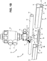
FIG. 1B illustrates another exploded, perspective view of the system for managing flexible tubing illustrated inFIG. 1A . -
FIG. 1C illustrates a schematic view of a valve actuator that is used to pinch flexible tubing. The pinching element extends and pinches the flexible tubing and creates a "Closed" state. When the actuator is retracted, the flexible tubing is not pinched and creates an "Open" state. -
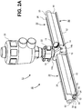
FIG. 2A illustrates a perspective view of the system for managing flexible tubing according to the embodiment ofFIGS. 1A and1B . The flexible conduit is passing through the passageway of the valve and being positioned within the conduit channel of the two conduit tracks that book-end the valve. A connector extends the length of conduit tracks and valve body. -
FIG. 2B illustrates an end view of the system ofFIG. 2A . The flexible conduit can be seen within the conduit channel. The connector is inserted into the connector channel which is located on the opposing side of the conduit channel. -
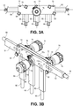
FIG. 3A illustrates another embodiment of a system for managing flexible tubing that incorporates multiple valves. -
FIG. 3B is a perspective view of the system ofFIG. 3A . This illustrates one valve located on one side of the valve assembly while two valves are located on an opposing side. -
FIG. 4A illustrates a perspective view of another multi-valve embodiment. -
FIG. 4B illustrates another perspective view of the multi-valve embodiment ofFIG. 4A . -
FIG. 4C illustrates yet another perspective view of the multi-valve embodiment ofFIG. 4A . -
FIGS. 5A illustrates an embodiment in which multiple different shapes (or lengths) of conduit tracks can be combined with other process components (e.g., a valve is illustrated) to manage the location and direction of the flexible conduit.FIG. 5A illustrates the modular components prior to assembly. -
FIG. 5B illustrates the assembled components ofFIG. 5A . -
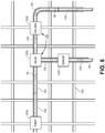
FIG. 6 illustrates an embodiment where multiple conduit tracks are connected to one another as well as different process components and hold a flexible conduit or tubing. A scaffold or support structure is illustrated which can be used to mount the conduit tracks and/or process components. -
FIGS. 1A and1B illustrate asystem 10 for managing flexible conduit (e.g., tubing) according to one embodiment. As noted herein, thesystem 10 has particular applicability for pharmaceutical, chemical, bioprocess, and food/diary manufacturing operations. Thesystem 10 is used, for example, to manage the layout and physical location of various components used in a fluid-based manufacturing process.FIGS. 1A and1B illustrate avalve 12 being interposed between and connected to two segments ofconduit track flexible conduit 60 is illustrated and passes through thevalve 12 and is secured in place to the two segments ofconduit track flexible conduit 60 is used to carry a fluid, typically although not exclusively at low pressures. Theflexible conduit 60 may include silicone however other materials may be used. These include, for example, a polymer such as thermoplastic elastomers (TPE), thermoplastic rubber (TPR), or the like. Theflexible conduit 60 may be unreinforced or reinforced. Theflexible conduit 60 includes a central lumen through which fluid passes. Theflexible conduit 60 may have a variety of sizes. For example, without limiting the invention, theflexible conduit 60 may have an internal diameter of 9.53 mm (0.375 inches) and an outer diameter of 15.88 mm (0.625 inches). Of course, this is just illustrative and other diameters may also be used. The invention is not limited by the size of theflexible conduit 60 that is used. - Still referring to
FIGS. 1A and1B , avalve 12 is illustrated being secured around theflexible conduit 60. Thevalve 12 includes avalve body 14 that is hinged viahinge 16 and forms first andsecond body portions valve body 14 is typically made from a metallic material but it could also be formed from a suitably hard plastic or other polymer material. The first andsecond body portions FIG. 1A and1B ), define apassageway 18 that extends through thevalve body 14 that receives theflexible conduit 60. The first andsecond body portions fastener 19. Thefastener 19 as illustrated inFIG. 1A and1B may include a threaded latch and knob that can be tightened or loosened on the threaded latch to selectively close/open thevalve body 14. The size and shape of thepassageway 18 is such that theflexible conduit 60 fits snuggly therein. For example, the inner diameter of thepassageway 18 may closely match the outer diameter of theflexible conduit 60. As seen inFIG. 1A , avalve actuator 20 is disposed on thevalve body 14. In this embodiment, aclamp 22 is used to secure thevalve actuator 20 to thevalve body 14. The use of theclamp 22 is optional, however. In some embodiments, thevalve actuator 20 may be directly integrated with thevalve body 14. Theactuator 20 includes a pinchingelement 24 as seen inFIG. 1C that moves in the direction of the arrow to selectively close/open thecentral lumen 62 of theflexible conduit 60. Theactuator 20 may be moved using any number approaches. For example, theactuator 20 may be pneumatically actuated valves usingair ports 21. Theactuator 20 may also be manually advanced/retracted using a bonnet or the like that is manually rotated. Theactuator 20 may also be actuated using a manually-activated toggle-type mechanism that does not require rotation of a bonnet or the like. This enables one to rapidly switch the valve between on/off states. - Still referring to
FIGS. 1A and1B , conduit tracks 30, 32 are illustrated adjacent to thevalve 12 with eachconduit track valve 12. The conduit tracks 30, 32 are used to hold theflexible conduit 60 in place in the desired spatial configuration (e.g., length, shape, and the like). The conduit tracks 30, 32 may be made of any material (e.g., polymer or plastic-based) and are typically rigid or semi-rigid. In this example, the conduit tracks 30, 32 are straight segments of track although other shapes may be used (e.g., curves, bends and the like may be integrated into the track). Eachconduit track respective conduit channel conduit track flexible conduit 60. Theconduit channels conduit channels flexible conduit 60 can be clipped into position. Theflexible conduit 60 is pressed into theconduit channels flexible conduit 60 during insertion and removal may occur). The opening of eachconduit channel flexible conduit 60 so that theflexible conduit 60 is securely retained therein. Eachconduit track respective connector channel FIGS. 1A and1B . Theconnector channel conduit channels connector channel walls conduit channels respective retaining tabs tabs connector channels - As seen in
FIGS. 1A and1B , aconnector 50 is used to connect thevalve body 14 to the conduit tracks 30, 32. Theconnector 50 may be formed from a rigid piece of material (e.g., polymer, plastic-based, or even metal) that is used to connect thevalve 12 to the adjacent conduit tracks 30, 32. As seen inFIG. 1A and1B , theconnector 50 includes a base 52 with a pair of retainingmembers 54 that extend along a length of theconnector 50. The pair of retainingmembers 54 includes angled walls or edges as seen inFIG. 1A . The retainingmembers 54 may be continuous along the length of theconnector 50 or they may be interrupted. The retainingmembers 54 inFIGS. 1A and1B have acorresponding tab 56 along their length that engages with thecorresponding tabs connector channels connector 50 is secured securely to theconnector channels valve body 14. Thevalve body 14 includes a mountingchannel 15 that is located in in thevalve body 14 and configured to mate with the retainingmembers 54 andtab 56 of theconnector 50. The mountingchannel 15 as illustrated inFIGS. 1A and1B is a notched channel located in one of the twohalves valve body 14 that has notched surfaces that engage with the retainingmembers 54 andtab 56. Theconnector 50 can be inserted laterally into theconnector channels channel 15. Alternatively, in some embodiments, theconnector 50 may be pressed directly into theconnector channels channel 15 whereby the retainingmembers 54 flex and then lock into place (e.g., theconnector 50 snaps into place after being pressed into the mountingchannel 15 andconnector channels 38, 40). -
FIGS. 2A and2B illustrate the embodiment ofFIGS. 1A and1B with theflexible conduit 60 shown inserted into theconduit channels flexible conduit 60 is thus clipped or otherwise secured into place. Theflexible conduit 60 may be removed from theconduit channels valve body 14 using by unlocking thefastener 19. Theflexible conduit 60 can then be pulled out of theconduit channels channels flexible conduit 60 from the clipping structure of theconduit channels FIG. 2A , in this embodiment the length of theconnector 50 is such that it traverses thevalve body 14 as well as the conduit tracks 30, 32. The length of theconnector 50 may vary. In an alternative embodiment,multiple connectors 50 can be used to connect the conduit tracks to thevalve body 14. For example, afirst connector 50 that is secured to theconduit track 30 could partially extend into the mountingchannel 15 while asecond connector 50 that is secured to theother conduit track 32 could partially extend into the mountingchannel 15. -
FIGS. 3A and 3B illustrate another embodiment of asystem 10 that uses avalve assembly 70 that holdsmultiple valves 74 secured to thevalve assembly 70 usingclamps 78. Thevalve assembly 70 is similar to the prior embodiment in that it includes a valve body having afirst half 70a and asecond half 70b that are connected via ahinge 72 or multiple hinges 72. The internal surfaces of thevalve assembly 70 define a passageway that holds theflexible conduit 60. In this embodiment, theflexible conduit 60 includes several branches along with a main line. The passages within the first andsecond halves flexible conduit 60. Thevalve assembly 70 is secured in the closed state usingmultiple fasteners 80 like thefasteners 19 described in the prior embodiment. - In this embodiment, there are three
valves 74 that are secured to thevalve assembly 70. Eachvalve 74 has itsown actuator 76 and operates a pinching element (not shown) that works as described with respect to the embodiment ofFIGS. 1A ,1B to pinch theflexible conduit 60. In this embodiment, thevalves 76 are located so that fluid can be selectively switched into the various branch channels depending on which valves are opened or closed. As seen inFIGS. 3A and 3B , there are five (5) conduit tracks 84, 86, 88, 90, 92 that are connected to thevalve assembly 70 and contain theflexible conduit 60 within respective conduit channels (as described previously). In this embodiment, there areseparate connectors 94 that connect the various conduit tracks 84, 86, 88, 90, 92 to thevalve assembly 70. Alternatively, there could be fewer connectors if one or more connectors are lengthened and inserted into multiple conduit tracks 84, 86, 88, 90, 92. Theconnectors 94 may formed as described above in the prior embodiments and may interface with thevalve assembly 70 and the conduit tracks 84, 86, 88, 90, 92 as explained previously. Alternatively, thevalve assembly 70 may haveconnectors 94 that are permanently formed in thevalve assembly 70 and interface with the conduit tracks 84, 86, 88, 90, 92. For example, theconnector 94 may include a "male" extension or connector that interfaces with corresponding "female" channels or slots formed in the conduit tracks 84, 86, 88, 90, 92 (e.g.,connector channel FIGS. 1A and1B ). In still another alternative construction, the conduit tracks 84, 86, 88, 90, 92 may have a male extension orconnector 94 that is fixed to the respective track and interfaces with a female slot or channel (e.g., mountingchannel 15 ofFIGS. 1A and1B ) formed in thevalve assembly 70. These alternative designs of theconnectors 94 may also be used with the embodiments described inFIGS. 1A ,1B ,2A , and2B . While three (3)valves 76 are illustrated, there could be additional orfewer valves 76 and the invention is not limited by the number ofvalves 76. -
FIGS. 4A-4C illustrate another embodiment of asystem 10 that has avalve assembly 70 that includesmultiple valves 74 positioned thereon. In this embodiment, there are six (6)valves 74 that are disposed on or otherwise connected to thevalve assembly 70. Eachvalve 74 has itsown actuator 76 and operates a pinching element (not shown) that works as described with respect to the embodiment ofFIGS. 1A ,1B to pinch theflexible conduit 60 that is positioned between twohalves valve assembly 70 that are connected viahinge 72. Fasteners 80 (e.g., latches with knobs as described previously) may be used to secure the twohalves valve assembly 70 together. In addition,optional clamps 78 may be used to secure thevalves 74 to thevalve assembly 70 as illustrated. Alternatively, thevalves 76 may be directly incorporated into thevalve assembly 70. In this embodiment, thevalves 76 are located so that fluid can be selectively switched into the various branch channels depending on which valves are opened or closed. As best seen inFIG. 4A , there areapertures 77 located invalve assembly half 70a that allow passage of the pinching element (e.g., pinchingelement 24 ofFIG. 1C ) so that theflexible conduit 60 can be pinched (closed) or un-pinched (open). Twosuch apertures 77 are located in themain passageway 18a while fourapertures 77 are located inbranch passageways 18b. - As seen in
FIGS. 4A-4C , there are six (6) conduit tracks 84, 86, 88, 90, 92, 93 that are connected to thevalve assembly 70 and contain theflexible conduit 60 within respective conduit channels (as described previously, for example, inFIGS. 1A ,1B ,2A ,2B ). In this embodiment, there are six (6) separate connectors 94 (as described previously, for example, inFIGS. 1A ,1B ,2A ,2B ) that connect the various conduit tracks 84, 86, 88, 90, 92, 93 to thevalve assembly 70. As best seen inFIGS. 4B and4C , mountingchannels 15 are located in thevalve assembly half 70b. The mountingchannels 15 are formed as a notched channel that has notched surfaces that engage with corresponding surfaces and tabs of the connectors 94 (described previously). Theconnectors 94 connect the respective conduit tracks 84, 86, 88, 90, 92, 93 to thevalve assembly 70 via the mountingchannels 15. Note that in one alternative embodiment, a singlelong connector 94 could be used that connects both conduit tracks 84 and 93. - In another alternative embodiment, the
connectors 94 could be omitted from the interface between thevalve assembly 70 and the conduit tracks 84, 86, 88, 90, 92, 93. For example, thevalve assembly 70 could have "connectors" integrated in thevalve assembly 70. These, for example, could include "male" extensions that are formed integrally into thevalve assembly 70 and insert into the connector channels of the conduit tracks 84, 86, 88, 90, 92, 93. In yet another alternative, the conduit tracks 84, 86, 88, 90, 92, 93 that interface with thevalve assembly 70 could have "male" ends that integrate with the mountingchannels 15. These alternative embodiments would eliminate the need to haveconnectors 94 at the interface between the conduit tracks 84, 86, 88, 90, 92, 93 and thevalve assembly 70. Note that these alternative designs may also apply to the embodiments ofFIGS. 1A ,1B ,2A , and2B . -
FIGS. 5A and 5B illustrate the modular nature of thesystem 10 that is described herein. Various components can be mixed and matched in various combinations and setups to achieve the desired of spatial arrangement of components. In the very basic example ofFIGS. 5A and 5B asingle valve 100 is illustrated along with two straight conduit tracks 102, 104 and a curved segment ofconduit track 106. Twoconnectors FIG. 5B , the two straight conduit tracks 102, 104 are connected to one another using theconnector 108. Theother connector 110 connects to one end of the straight conduit track (e.g., conduit track 104) and extends through the valve 100 (e.g. using amount channel 15 of the type illustrated inFIG. 1A ) and connects with the curved segment ofconduit track 106. Of course, this example just illustrates a very small portion of the overall hierarchy of the system. Once can imaging that a full manufacturing process will have many different components that are connected together. Thus, many conduit tracks of a variety of different sizes, shapes, and geometries can be employed. Further, while the embodiments described herein have utilized a valve or multiple valves positioned between different conduit tracks there could be other components that are connected to conduit tracks. This includes, for example, pumps, sensors, filters, chromatography columns, reaction volumes (e.g., reactor), reservoirs, manifolds, and the like. - The conduit tracks with the
flexible conduit 60 contained therein may be optionally mounted on a support or scaffold to further aid in spatially arranging components. The support of scaffold may be secured to the ground, ceiling (e.g., hung), or on the walls of a manufacturing facility. The scaffolding or support could also be located on a moveable cart or the like for other applications. The conduit tracks could be mounted using a variety of different fasteners such as zip ties, clips, screws, or even adhesives.FIG. 6 illustrates an embodiment where multiple conduit tracks 120 are connected to one another as well asdifferent process components 122.Illustrated process components 122 include apump 122a,valve 122b,sensor 122c, andcolumn 122d, although other process components may be included. A flexible conduit ortubing 60 is illustrated being mounted in the conduit tracks 120 and passing through thevarious process components 122. In this embodiment, a scaffold orsupport 130 is also illustrated that can be used to mount the conduit tracks 120 and/or theprocess components 122. - As seen in the embodiments described herein, the various conduit tracks are seen as being located adjacent to the valve body or valve assembly. Note that these adjacent conduit tracks need not necessarily abut with the valve body or valve assembly. There may be a gap between an adjacent conduit track and the valve body/valve assembly. Of course, in other embodiments, the conduit tracks may physically abut with the valve body/valve assembly. Moreover, while the valve body/valve assembly has been described as interfacing with a connector, in some alternative embodiments, the valve body/valve assembly may be secured directly to the conduit track without the need for a separate connector. In addition, in the illustrated embodiments, a
clamp various valves actuators valve body 14 orvalve assembly 70. In some alternative embodiments, there are not clamps and thevalves actuators valve body 14 orvalve assembly 70. - Applicant has thus described a flexible conduit management system that can be used to organize and layout flexible conduit that is used as part of a liquid-based manufacturing process. The conduit tracks are used to secure the flexible conduit in a fixed location and desired shape. Each conduit track includes a conduit channel for holding the flexible conduit. The flexible conduit can easily be loaded into and out of the conduit channel. For example, for aspetic or sterile applications, the flexible conduit can quickly be replaced with another flexible conduit while using the same conduit tracks. The conduit tracks include on an opposing side a connector channel that has walls or the like to define a slot that receives a rigid or semi-rigid connector. The connector enables the conduit tracks to be connected to other conduit tracks or other process components such as valves, pumps, filters, columns, reservoirs, sensors, and the like. For example, the process component may have a mounting channel or other slot that receives the connector so that a conduit channel can be secured relative to the process component. The connector acts as a tongue that is inserted into a slot or channel on a conduit track or other process component. Various lengths of flexible conduits can be used. For example, multiple segments of flexible conduit may be connected to one another using standard connectors such as clamps can be used. Alternatively, a long length of flexible conduit that traverses many conduit tracks and process components can be used.
- In the embodiments described herein the connectors may be separate in which case they are inserted into the various connector channels on the conduit tracks or mounting channels on process components. Alternatively, the connector may be fixed to a conduit track or process component and inserted into the connector channel or mounting channel of an adjacent component. It should be understood that while various embodiments are described herein various feature of one embodiment may be combined or used with another embodiment. That is to say, features of one embodiment may be substituted or used in another embodiment. While embodiments of the present invention have been shown and described, various modifications may be made without departing from the scope of the present invention. The invention, therefore, should not be limited, except to the following claims.
Claims (14)
- A system (10) for managing flexible conduit or tubing (60) used in pharmaceutical, bioprocess, or food/dairy applications comprising:a segment of flexible conduit or tubing (60); anda plurality of conduit tracks (30, 32; 84, 86, 88, 90, 92; 102, 104, 106), each conduit track including a conduit channel (34,36) disposed on a first side thereof and extending along the length of each respective conduit track and dimensioned to receive the segment of flexible conduit or tubing (60) therein, each conduit track (30, 32, 102, 104, 106) further including a connector channel (38, 40) disposed on a second, opposing side and extending along the length of each respective conduit track, wherein each connector channel (38, 40) is formed by a pair of walls (42, 44) that extend from the conduit channels (34, 36) and terminate at respective retaining tabs (46, 48), characterized in that each connector channel (38, 40) contains one or more connectors (50; 94; 108, 110) that connect adjacent conduit tracks (30, 32; 84, 86, 88, 90, 92; 102, 104, 106) in an end-to-end fashion, each of the one or more connectors (50; 94; 108, 110) comprising a base (52) with a pair of retaining members (54) that extend along a length of the connector (50; 94; 108, 110), wherein the pair of retaining members (54) includes angled walls or edges having tabs (56) formed along their length that engage with the corresponding retaining tabs (46, 48) in the connector channels (38, 40).
- The system (10) of claim 1, further including one or more of a pump (122a), valve (12, 122b), sensor (122c), filter, chromatography column, elution column, reactor, reservoir, and manifold interposed between at least two conduit tracks (30, 32; 84, 86, 88, 90, 92; 102, 104, 106).
- The system (10) of any one of claims 1 and 2, wherein the conduit channels (34, 36) are C-shaped or semi-annular.
- The system (10) of any one of claims 1-3, wherein the plurality of conduit tracks (30, 32; 84, 86, 88, 90, 92; 102, 104, 106) and the segment of flexible conduit or tubing (60) are mounted on a scaffold or support structure using fasteners.
- The system (10) of claim 4, wherein the scaffold or support structure is located on a cart.
- The system (10) of any one of claims 1-5, wherein the plurality of conduit tracks (30, 32; 84, 86, 88, 90, 92; 102, 104, 106) comprise conduit tracks of different shapes.
- The system (10) of claim 6, wherein the plurality of conduit tracks (102, 104, 106) comprises straight conduits tracks (102, 104) and curved conduit tracks (106).
- The system (10) of any one of claims 1-7, further comprising a valve body (14) or valve assembly (12; 74; 100) containing the flexible conduit or tubing (60) therein and interfacing with one or more of the conduit tracks (30, 32; 84, 86, 88, 90, 92; 102, 104, 106).
- The system (10) of claim 8, wherein the valve body (14) or valve assembly (12; 74; 100) comprises a mounting channel (15) and wherein the pair of angled walls or edges (54) of the retaining members (54) are configured to mate with the mounting channel (15).
- The system (10) of claim 9, wherein the mounting channel (15) comprises a notched channel and the angled walls or edges (54) with the respective retaining tabs (56) engage with the notched channel to secure the valve body (14) or valve assembly (12; 74, 100) to the connector.
- The system (10) of any one of claims 8-10, wherein the valve body (14) or valve assembly (12) interfaces with a first conduit track (30) and a second conduit track (32) and a single connector (50), wherein the length of the connector (5) is such that it traverses the valve bodoy (14) as well as the first and second conduit tracks (30, 32).
- The system (10) of any one of claims 1-11, wherein each conduit channel (34,36) is continuous along the length of the respective conduit track.
- The system (10) of any one of claims 1-11, wherein each conduit channel (34,36) is interrupted along the length of the respective conduit track.
- A method of using the system of any one of claims 1-13 comprising removing and inserting the segment of flexible conduit or tubing into the conduit channels of the plurality of conduit tracks.
Priority Applications (1)
| Application Number | Priority Date | Filing Date | Title |
|---|---|---|---|
| EP21174602.9A EP3950042A1 (en) | 2015-09-15 | 2016-09-14 | Flexible tubing management system for pharmaceutical, bioprocess applications, and food/dairy applications |
Applications Claiming Priority (2)
| Application Number | Priority Date | Filing Date | Title |
|---|---|---|---|
| US201562218974P | 2015-09-15 | 2015-09-15 | |
| PCT/US2016/051714 WO2017048831A1 (en) | 2015-09-15 | 2016-09-14 | Flexible tubing management system for pharmaceutical, bioprocess applications, and food/dairy applications |
Related Child Applications (2)
| Application Number | Title | Priority Date | Filing Date |
|---|---|---|---|
| EP21174602.9A Division EP3950042A1 (en) | 2015-09-15 | 2016-09-14 | Flexible tubing management system for pharmaceutical, bioprocess applications, and food/dairy applications |
| EP21174602.9A Division-Into EP3950042A1 (en) | 2015-09-15 | 2016-09-14 | Flexible tubing management system for pharmaceutical, bioprocess applications, and food/dairy applications |
Publications (3)
| Publication Number | Publication Date |
|---|---|
| EP3349843A1 EP3349843A1 (en) | 2018-07-25 |
| EP3349843A4 EP3349843A4 (en) | 2019-05-15 |
| EP3349843B1 true EP3349843B1 (en) | 2021-06-30 |
Family
ID=58289848
Family Applications (2)
| Application Number | Title | Priority Date | Filing Date |
|---|---|---|---|
| EP16847224.9A Active EP3349843B1 (en) | 2015-09-15 | 2016-09-14 | Flexible tubing management system for pharmaceutical, bioprocess applications, and food/dairy applications |
| EP21174602.9A Withdrawn EP3950042A1 (en) | 2015-09-15 | 2016-09-14 | Flexible tubing management system for pharmaceutical, bioprocess applications, and food/dairy applications |
Family Applications After (1)
| Application Number | Title | Priority Date | Filing Date |
|---|---|---|---|
| EP21174602.9A Withdrawn EP3950042A1 (en) | 2015-09-15 | 2016-09-14 | Flexible tubing management system for pharmaceutical, bioprocess applications, and food/dairy applications |
Country Status (6)
| Country | Link |
|---|---|
| US (3) | US10612681B2 (en) |
| EP (2) | EP3349843B1 (en) |
| JP (2) | JP6955769B2 (en) |
| KR (1) | KR102653403B1 (en) |
| CN (1) | CN108025168B (en) |
| WO (1) | WO2017048831A1 (en) |
Families Citing this family (9)
| Publication number | Priority date | Publication date | Assignee | Title |
|---|---|---|---|---|
| EP3349843B1 (en) | 2015-09-15 | 2021-06-30 | Repligen Corporation | Flexible tubing management system for pharmaceutical, bioprocess applications, and food/dairy applications |
| SG11201906632WA (en) | 2017-01-31 | 2019-08-27 | Alphinity Llc | Bioprocess vessels with integrated pump |
| EP3381530A1 (en) | 2017-03-29 | 2018-10-03 | EMD Millipore Corporation | Facility for treating a biological fluid |
| EP3381529A1 (en) | 2017-03-29 | 2018-10-03 | EMD Millipore Corporation | Facility for treating a biological fluid |
| CN109578691B (en) * | 2018-12-25 | 2020-07-24 | 嵊州市越通非开挖建设有限公司 | Be used for inclined plane pipeline integral erection device |
| HUE068931T2 (en) * | 2019-01-22 | 2025-02-28 | Adventia Pharma S L | Feeding cap, drive head, and drive system |
| WO2022066668A1 (en) * | 2020-09-22 | 2022-03-31 | Alphinity Usa, Inc. | Systems and methods for the preparation of fluids for bioprocess and pharmaceutical applications |
| CN114576387B (en) * | 2022-02-17 | 2024-08-13 | 马俊 | Fluid hose clamp pipe valve |
| WO2025080456A1 (en) * | 2023-10-09 | 2025-04-17 | Repligen Corporation | Pneumatic actuator assembly for reduced dead leg |
Family Cites Families (55)
| Publication number | Priority date | Publication date | Assignee | Title |
|---|---|---|---|---|
| US2825524A (en) * | 1956-12-17 | 1958-03-04 | Knox P Fox | Pinch valve |
| US2931387A (en) | 1957-08-22 | 1960-04-05 | Robertson Co H H | Control apparatus for domestic water distribution system |
| GB1055426A (en) | 1963-11-22 | 1967-01-18 | Kelsto Engineering Company Ltd | Improvements in or relating to pinch valves |
| US4254797A (en) | 1979-01-26 | 1981-03-10 | Bi-M Instrument Company | Apparatus for producing calibration gases suitable for analytical instrumentation |
| US4993456A (en) | 1982-03-02 | 1991-02-19 | Akos Sule | Pinch valve assembly |
| US4618114A (en) * | 1982-09-29 | 1986-10-21 | Lof Plastics Inc. | Conduit spacer and support |
| FR2576386B1 (en) * | 1985-01-18 | 1987-03-20 | Lesourd Hugues | TAP CONNECTED TO AT LEAST TWO SUPPLY PIPES, IN PARTICULAR FOR SANITARY FACILITIES AND SERVING SEPARATE OR MIXED OF AT LEAST TWO DIFFERENT LIQUIDS |
| JPS647979U (en) | 1987-07-03 | 1989-01-17 | ||
| US4895341A (en) | 1988-09-30 | 1990-01-23 | Whitey Co. | Pinch valve |
| US5165874A (en) * | 1990-05-04 | 1992-11-24 | Block Medical, Inc. | Disposable infusion apparatus and peristaltic pump for use therewith |
| US5078683A (en) * | 1990-05-04 | 1992-01-07 | Block Medical, Inc. | Programmable infusion system |
| DE4224167C2 (en) | 1992-07-22 | 1994-11-24 | Bundesrep Deutschland | Device for holding catheter connections |
| US5197708A (en) | 1992-08-11 | 1993-03-30 | Flow-Rite Controls, Ltd. | Tubing pinch valve device |
| US5402823A (en) * | 1992-12-07 | 1995-04-04 | George S. Cole & Associates, Incorporated | Pinch valve |
| US5350290A (en) | 1993-01-19 | 1994-09-27 | Amf Machinery Systems, Inc. | Manifold and valving arrangement for dough divider |
| US5549134A (en) | 1994-05-27 | 1996-08-27 | Marcvalve Corporation | Diaphragm valve |
| JP3486238B2 (en) * | 1994-09-21 | 2004-01-13 | Smc株式会社 | Switching valve |
| AU713503B2 (en) | 1995-09-21 | 1999-12-02 | Abbott Laboratories | Tension responsive pinch valve |
| US6068751A (en) | 1995-12-18 | 2000-05-30 | Neukermans; Armand P. | Microfluidic valve and integrated microfluidic system |
| US5901745A (en) * | 1997-06-19 | 1999-05-11 | The Hoover Company | Multi-solution dispensing valve |
| EP1009944A4 (en) | 1997-07-03 | 2004-06-30 | Prec Dispensing Systems Ltd | FLEXIBLE TUBE PINCHING MECHANISM |
| JP4023638B2 (en) * | 1997-09-17 | 2007-12-19 | 因幡電機産業株式会社 | Piping cover |
| US6036166A (en) | 1997-09-25 | 2000-03-14 | Imi Cornelius Inc. | Chamber valve |
| IT1297329B1 (en) | 1997-11-26 | 1999-09-01 | Teseo Srl | SYSTEM OF ELEMENTS FOR THE FORMATION OF MODULAR PIPES IN EXTRUDED PROFILE |
| WO1999045302A1 (en) | 1998-03-05 | 1999-09-10 | The Swagelok Company | Modular surface mount manifold |
| US6502601B2 (en) * | 1998-03-05 | 2003-01-07 | Swagelok Company | Modular surface mount manifold assemblies |
| US6036107A (en) * | 1998-03-31 | 2000-03-14 | Spraying System Co. | Control valve arrangement for spraying systems |
| AU4002699A (en) * | 1998-05-18 | 1999-12-06 | Swagelok Company, The | Modular surface mount manifold assemblies |
| WO2000025049A1 (en) | 1998-10-23 | 2000-05-04 | Chemand Corporation | Fluid handling port array |
| DE10035763B4 (en) | 2000-07-22 | 2006-07-27 | Nucellsys Gmbh | Device for dosing a gaseous medium |
| US7500949B2 (en) * | 2002-03-01 | 2009-03-10 | Medtronic Minimed, Inc. | Multilumen catheter |
| US7104275B2 (en) | 2002-04-01 | 2006-09-12 | Emerson Electric Co. | Pinch valve |
| US20040163711A1 (en) | 2003-02-20 | 2004-08-26 | Graham Packaging Company, L.P. | Fluid regulating pinch valve |
| JP2004293769A (en) | 2003-03-28 | 2004-10-21 | Japan Aviation Electronics Industry Ltd | Flow controller |
| US6799607B1 (en) | 2003-06-18 | 2004-10-05 | Pbm, Inc. | Sanitary conduit support systems and methods |
| US6976664B2 (en) | 2003-08-11 | 2005-12-20 | Mitos Technologies, Inc. | Free flow valve and element |
| US8038639B2 (en) | 2004-11-04 | 2011-10-18 | Baxter International Inc. | Medical fluid system with flexible sheeting disposable unit |
| US7048008B2 (en) * | 2004-04-13 | 2006-05-23 | Ultra Clean Holdings, Inc. | Gas-panel assembly |
| JP4597564B2 (en) * | 2004-04-28 | 2010-12-15 | 矢崎総業株式会社 | Clip structure and fixing method |
| US7383853B2 (en) | 2004-09-07 | 2008-06-10 | Parker-Hannifin Corp. | Multi-port free flow valve and element |
| US7819139B2 (en) | 2005-07-14 | 2010-10-26 | Pdc Facilities, Inc. | Liner for a flow meter |
| US20070295867A1 (en) | 2006-06-21 | 2007-12-27 | Hennon John | Conduit support apparatus |
| EP2049821A4 (en) | 2006-07-21 | 2013-09-04 | Amgen Inc | BREAKING VALVE |
| JP4994082B2 (en) | 2007-03-30 | 2012-08-08 | 旭有機材工業株式会社 | Piping material |
| US8091455B2 (en) * | 2008-01-30 | 2012-01-10 | Cummins Filtration Ip, Inc. | Apparatus, system, and method for cutting tubes |
| FR2939348B1 (en) * | 2008-12-10 | 2014-10-10 | Sartorius Stedim Biotech Sa | SECTIONING A FLEXIBLE TUBE FOR BIOPHARMACEUTICAL APPLICATIONS |
| US8282046B2 (en) * | 2009-02-12 | 2012-10-09 | Becton, Dickinson And Company | Systems and methods for organizing and priming an IV administration set |
| US8235067B2 (en) | 2009-05-15 | 2012-08-07 | Alphabio, Inc. | Encapsulated valve system |
| JP5364493B2 (en) * | 2009-07-29 | 2013-12-11 | 株式会社ブリヂストン | Header fixing tool and header fixing structure |
| DE102010043865A1 (en) * | 2009-11-30 | 2011-07-14 | Horiba Stec Co., Ltd. | Fluid device |
| FR2961711B1 (en) * | 2010-06-23 | 2012-08-17 | Millipore Corp | POCKET FOR CIRCUIT OF A BIOLOGICAL LIQUID TREATMENT FACILITY |
| US8979070B2 (en) * | 2010-09-10 | 2015-03-17 | William Keizer | Clamshell housing for dispensing tube of metering dispenser |
| FR2970315A1 (en) * | 2011-01-07 | 2012-07-13 | Peugeot Citroen Automobiles Sa | Reinforcement device for flexible element i.e. hose, of brake fluid reservoir for connecting reservoir to master cylinder within engine compartment of car, has reinforcement unit mounted on flexible element in removable manner |
| US20120286110A1 (en) * | 2011-05-10 | 2012-11-15 | Hill Douglas C | Conduit support |
| EP3349843B1 (en) * | 2015-09-15 | 2021-06-30 | Repligen Corporation | Flexible tubing management system for pharmaceutical, bioprocess applications, and food/dairy applications |
-
2016
- 2016-09-14 EP EP16847224.9A patent/EP3349843B1/en active Active
- 2016-09-14 WO PCT/US2016/051714 patent/WO2017048831A1/en not_active Ceased
- 2016-09-14 US US15/759,794 patent/US10612681B2/en active Active
- 2016-09-14 CN CN201680053229.9A patent/CN108025168B/en active Active
- 2016-09-14 KR KR1020187010190A patent/KR102653403B1/en active Active
- 2016-09-14 JP JP2018513355A patent/JP6955769B2/en not_active Expired - Fee Related
- 2016-09-14 EP EP21174602.9A patent/EP3950042A1/en not_active Withdrawn
-
2020
- 2020-02-18 US US16/794,160 patent/US11231120B2/en not_active Expired - Fee Related
-
2021
- 2021-08-17 US US17/404,495 patent/US11578809B2/en active Active
- 2021-09-27 JP JP2021156313A patent/JP7278639B2/en active Active
Non-Patent Citations (1)
| Title |
|---|
| None * |
Also Published As
| Publication number | Publication date |
|---|---|
| CN108025168B (en) | 2021-05-04 |
| JP2022003272A (en) | 2022-01-11 |
| US11578809B2 (en) | 2023-02-14 |
| JP6955769B2 (en) | 2021-10-27 |
| WO2017048831A1 (en) | 2017-03-23 |
| US11231120B2 (en) | 2022-01-25 |
| US20180252326A1 (en) | 2018-09-06 |
| EP3950042A1 (en) | 2022-02-09 |
| US10612681B2 (en) | 2020-04-07 |
| KR20180052716A (en) | 2018-05-18 |
| US20200326004A1 (en) | 2020-10-15 |
| JP2018534491A (en) | 2018-11-22 |
| JP7278639B2 (en) | 2023-05-22 |
| US20210372540A1 (en) | 2021-12-02 |
| CN108025168A (en) | 2018-05-11 |
| EP3349843A4 (en) | 2019-05-15 |
| EP3349843A1 (en) | 2018-07-25 |
| KR102653403B1 (en) | 2024-04-02 |
Similar Documents
| Publication | Publication Date | Title |
|---|---|---|
| US11578809B2 (en) | Flexible tubing management system for pharmaceutical, bioprocess applications, and food/dairy applications | |
| US12460731B2 (en) | Valve assembly with directional flow path | |
| US12253189B2 (en) | Encapsulated valve system and method of use | |
| KR102400420B1 (en) | Encapsulated system for pressurized fluid processes | |
| IL207221A (en) | Sealing between a cannula part and a fluid path |
Legal Events
| Date | Code | Title | Description |
|---|---|---|---|
| STAA | Information on the status of an ep patent application or granted ep patent |
Free format text: STATUS: THE INTERNATIONAL PUBLICATION HAS BEEN MADE |
|
| PUAI | Public reference made under article 153(3) epc to a published international application that has entered the european phase |
Free format text: ORIGINAL CODE: 0009012 |
|
| STAA | Information on the status of an ep patent application or granted ep patent |
Free format text: STATUS: REQUEST FOR EXAMINATION WAS MADE |
|
| 17P | Request for examination filed |
Effective date: 20180316 |
|
| AK | Designated contracting states |
Kind code of ref document: A1 Designated state(s): AL AT BE BG CH CY CZ DE DK EE ES FI FR GB GR HR HU IE IS IT LI LT LU LV MC MK MT NL NO PL PT RO RS SE SI SK SM TR |
|
| AX | Request for extension of the european patent |
Extension state: BA ME |
|
| DAV | Request for validation of the european patent (deleted) | ||
| DAX | Request for extension of the european patent (deleted) | ||
| A4 | Supplementary search report drawn up and despatched |
Effective date: 20190412 |
|
| RIC1 | Information provided on ipc code assigned before grant |
Ipc: F16L 3/12 20060101ALI20190408BHEP Ipc: F16L 3/26 20060101ALI20190408BHEP Ipc: A61M 39/28 20060101AFI20190408BHEP Ipc: F16L 3/24 20060101ALI20190408BHEP Ipc: F16L 3/10 20060101ALI20190408BHEP Ipc: A61M 5/14 20060101ALI20190408BHEP Ipc: F16L 3/08 20060101ALI20190408BHEP Ipc: F16L 3/02 20060101ALI20190408BHEP |
|
| STAA | Information on the status of an ep patent application or granted ep patent |
Free format text: STATUS: EXAMINATION IS IN PROGRESS |
|
| 17Q | First examination report despatched |
Effective date: 20200319 |
|
| GRAP | Despatch of communication of intention to grant a patent |
Free format text: ORIGINAL CODE: EPIDOSNIGR1 |
|
| STAA | Information on the status of an ep patent application or granted ep patent |
Free format text: STATUS: GRANT OF PATENT IS INTENDED |
|
| INTG | Intention to grant announced |
Effective date: 20210112 |
|
| GRAS | Grant fee paid |
Free format text: ORIGINAL CODE: EPIDOSNIGR3 |
|
| GRAA | (expected) grant |
Free format text: ORIGINAL CODE: 0009210 |
|
| STAA | Information on the status of an ep patent application or granted ep patent |
Free format text: STATUS: THE PATENT HAS BEEN GRANTED |
|
| RAP1 | Party data changed (applicant data changed or rights of an application transferred) |
Owner name: REPLIGEN CORPORATION |
|
| AK | Designated contracting states |
Kind code of ref document: B1 Designated state(s): AL AT BE BG CH CY CZ DE DK EE ES FI FR GB GR HR HU IE IS IT LI LT LU LV MC MK MT NL NO PL PT RO RS SE SI SK SM TR |
|
| REG | Reference to a national code |
Ref country code: CH Ref legal event code: EP |
|
| REG | Reference to a national code |
Ref country code: AT Ref legal event code: REF Ref document number: 1405771 Country of ref document: AT Kind code of ref document: T Effective date: 20210715 |
|
| REG | Reference to a national code |
Ref country code: DE Ref legal event code: R096 Ref document number: 602016060108 Country of ref document: DE |
|
| REG | Reference to a national code |
Ref country code: IE Ref legal event code: FG4D |
|
| REG | Reference to a national code |
Ref country code: SE Ref legal event code: TRGR |
|
| REG | Reference to a national code |
Ref country code: LT Ref legal event code: MG9D |
|
| PG25 | Lapsed in a contracting state [announced via postgrant information from national office to epo] |
Ref country code: FI Free format text: LAPSE BECAUSE OF FAILURE TO SUBMIT A TRANSLATION OF THE DESCRIPTION OR TO PAY THE FEE WITHIN THE PRESCRIBED TIME-LIMIT Effective date: 20210630 Ref country code: HR Free format text: LAPSE BECAUSE OF FAILURE TO SUBMIT A TRANSLATION OF THE DESCRIPTION OR TO PAY THE FEE WITHIN THE PRESCRIBED TIME-LIMIT Effective date: 20210630 Ref country code: BG Free format text: LAPSE BECAUSE OF FAILURE TO SUBMIT A TRANSLATION OF THE DESCRIPTION OR TO PAY THE FEE WITHIN THE PRESCRIBED TIME-LIMIT Effective date: 20210930 |
|
| REG | Reference to a national code |
Ref country code: NL Ref legal event code: MP Effective date: 20210630 |
|
| REG | Reference to a national code |
Ref country code: AT Ref legal event code: MK05 Ref document number: 1405771 Country of ref document: AT Kind code of ref document: T Effective date: 20210630 |
|
| PG25 | Lapsed in a contracting state [announced via postgrant information from national office to epo] |
Ref country code: NO Free format text: LAPSE BECAUSE OF FAILURE TO SUBMIT A TRANSLATION OF THE DESCRIPTION OR TO PAY THE FEE WITHIN THE PRESCRIBED TIME-LIMIT Effective date: 20210930 Ref country code: RS Free format text: LAPSE BECAUSE OF FAILURE TO SUBMIT A TRANSLATION OF THE DESCRIPTION OR TO PAY THE FEE WITHIN THE PRESCRIBED TIME-LIMIT Effective date: 20210630 Ref country code: LV Free format text: LAPSE BECAUSE OF FAILURE TO SUBMIT A TRANSLATION OF THE DESCRIPTION OR TO PAY THE FEE WITHIN THE PRESCRIBED TIME-LIMIT Effective date: 20210630 Ref country code: GR Free format text: LAPSE BECAUSE OF FAILURE TO SUBMIT A TRANSLATION OF THE DESCRIPTION OR TO PAY THE FEE WITHIN THE PRESCRIBED TIME-LIMIT Effective date: 20211001 |
|
| PG25 | Lapsed in a contracting state [announced via postgrant information from national office to epo] |
Ref country code: SM Free format text: LAPSE BECAUSE OF FAILURE TO SUBMIT A TRANSLATION OF THE DESCRIPTION OR TO PAY THE FEE WITHIN THE PRESCRIBED TIME-LIMIT Effective date: 20210630 Ref country code: SK Free format text: LAPSE BECAUSE OF FAILURE TO SUBMIT A TRANSLATION OF THE DESCRIPTION OR TO PAY THE FEE WITHIN THE PRESCRIBED TIME-LIMIT Effective date: 20210630 Ref country code: EE Free format text: LAPSE BECAUSE OF FAILURE TO SUBMIT A TRANSLATION OF THE DESCRIPTION OR TO PAY THE FEE WITHIN THE PRESCRIBED TIME-LIMIT Effective date: 20210630 Ref country code: CZ Free format text: LAPSE BECAUSE OF FAILURE TO SUBMIT A TRANSLATION OF THE DESCRIPTION OR TO PAY THE FEE WITHIN THE PRESCRIBED TIME-LIMIT Effective date: 20210630 Ref country code: AT Free format text: LAPSE BECAUSE OF FAILURE TO SUBMIT A TRANSLATION OF THE DESCRIPTION OR TO PAY THE FEE WITHIN THE PRESCRIBED TIME-LIMIT Effective date: 20210630 Ref country code: NL Free format text: LAPSE BECAUSE OF FAILURE TO SUBMIT A TRANSLATION OF THE DESCRIPTION OR TO PAY THE FEE WITHIN THE PRESCRIBED TIME-LIMIT Effective date: 20210630 Ref country code: PT Free format text: LAPSE BECAUSE OF FAILURE TO SUBMIT A TRANSLATION OF THE DESCRIPTION OR TO PAY THE FEE WITHIN THE PRESCRIBED TIME-LIMIT Effective date: 20211102 Ref country code: RO Free format text: LAPSE BECAUSE OF FAILURE TO SUBMIT A TRANSLATION OF THE DESCRIPTION OR TO PAY THE FEE WITHIN THE PRESCRIBED TIME-LIMIT Effective date: 20210630 Ref country code: ES Free format text: LAPSE BECAUSE OF FAILURE TO SUBMIT A TRANSLATION OF THE DESCRIPTION OR TO PAY THE FEE WITHIN THE PRESCRIBED TIME-LIMIT Effective date: 20210630 |
|
| PG25 | Lapsed in a contracting state [announced via postgrant information from national office to epo] |
Ref country code: PL Free format text: LAPSE BECAUSE OF FAILURE TO SUBMIT A TRANSLATION OF THE DESCRIPTION OR TO PAY THE FEE WITHIN THE PRESCRIBED TIME-LIMIT Effective date: 20210630 |
|
| REG | Reference to a national code |
Ref country code: DE Ref legal event code: R097 Ref document number: 602016060108 Country of ref document: DE |
|
| PG25 | Lapsed in a contracting state [announced via postgrant information from national office to epo] |
Ref country code: DK Free format text: LAPSE BECAUSE OF FAILURE TO SUBMIT A TRANSLATION OF THE DESCRIPTION OR TO PAY THE FEE WITHIN THE PRESCRIBED TIME-LIMIT Effective date: 20210630 |
|
| PLBE | No opposition filed within time limit |
Free format text: ORIGINAL CODE: 0009261 |
|
| STAA | Information on the status of an ep patent application or granted ep patent |
Free format text: STATUS: NO OPPOSITION FILED WITHIN TIME LIMIT |
|
| REG | Reference to a national code |
Ref country code: BE Ref legal event code: MM Effective date: 20210930 |
|
| PG25 | Lapsed in a contracting state [announced via postgrant information from national office to epo] |
Ref country code: MC Free format text: LAPSE BECAUSE OF FAILURE TO SUBMIT A TRANSLATION OF THE DESCRIPTION OR TO PAY THE FEE WITHIN THE PRESCRIBED TIME-LIMIT Effective date: 20210630 Ref country code: AL Free format text: LAPSE BECAUSE OF FAILURE TO SUBMIT A TRANSLATION OF THE DESCRIPTION OR TO PAY THE FEE WITHIN THE PRESCRIBED TIME-LIMIT Effective date: 20210630 |
|
| 26N | No opposition filed |
Effective date: 20220331 |
|
| PG25 | Lapsed in a contracting state [announced via postgrant information from national office to epo] |
Ref country code: LU Free format text: LAPSE BECAUSE OF NON-PAYMENT OF DUE FEES Effective date: 20210914 Ref country code: IT Free format text: LAPSE BECAUSE OF FAILURE TO SUBMIT A TRANSLATION OF THE DESCRIPTION OR TO PAY THE FEE WITHIN THE PRESCRIBED TIME-LIMIT Effective date: 20210630 Ref country code: BE Free format text: LAPSE BECAUSE OF NON-PAYMENT OF DUE FEES Effective date: 20210930 |
|
| PG25 | Lapsed in a contracting state [announced via postgrant information from national office to epo] |
Ref country code: LT Free format text: LAPSE BECAUSE OF FAILURE TO SUBMIT A TRANSLATION OF THE DESCRIPTION OR TO PAY THE FEE WITHIN THE PRESCRIBED TIME-LIMIT Effective date: 20210630 |
|
| PG25 | Lapsed in a contracting state [announced via postgrant information from national office to epo] |
Ref country code: HU Free format text: LAPSE BECAUSE OF FAILURE TO SUBMIT A TRANSLATION OF THE DESCRIPTION OR TO PAY THE FEE WITHIN THE PRESCRIBED TIME-LIMIT; INVALID AB INITIO Effective date: 20160914 |
|
| PG25 | Lapsed in a contracting state [announced via postgrant information from national office to epo] |
Ref country code: CY Free format text: LAPSE BECAUSE OF FAILURE TO SUBMIT A TRANSLATION OF THE DESCRIPTION OR TO PAY THE FEE WITHIN THE PRESCRIBED TIME-LIMIT Effective date: 20210630 |
|
| P01 | Opt-out of the competence of the unified patent court (upc) registered |
Effective date: 20230608 |
|
| PGFP | Annual fee paid to national office [announced via postgrant information from national office to epo] |
Ref country code: IE Payment date: 20230710 Year of fee payment: 8 Ref country code: GB Payment date: 20230727 Year of fee payment: 8 |
|
| PGFP | Annual fee paid to national office [announced via postgrant information from national office to epo] |
Ref country code: SE Payment date: 20230710 Year of fee payment: 8 Ref country code: FR Payment date: 20230710 Year of fee payment: 8 Ref country code: DE Payment date: 20230718 Year of fee payment: 8 |
|
| PGFP | Annual fee paid to national office [announced via postgrant information from national office to epo] |
Ref country code: CH Payment date: 20231001 Year of fee payment: 8 |
|
| PG25 | Lapsed in a contracting state [announced via postgrant information from national office to epo] |
Ref country code: MK Free format text: LAPSE BECAUSE OF FAILURE TO SUBMIT A TRANSLATION OF THE DESCRIPTION OR TO PAY THE FEE WITHIN THE PRESCRIBED TIME-LIMIT Effective date: 20210630 |
|
| PG25 | Lapsed in a contracting state [announced via postgrant information from national office to epo] |
Ref country code: TR Free format text: LAPSE BECAUSE OF FAILURE TO SUBMIT A TRANSLATION OF THE DESCRIPTION OR TO PAY THE FEE WITHIN THE PRESCRIBED TIME-LIMIT Effective date: 20210630 |
|
| PG25 | Lapsed in a contracting state [announced via postgrant information from national office to epo] |
Ref country code: MT Free format text: LAPSE BECAUSE OF FAILURE TO SUBMIT A TRANSLATION OF THE DESCRIPTION OR TO PAY THE FEE WITHIN THE PRESCRIBED TIME-LIMIT Effective date: 20210630 |
|
| REG | Reference to a national code |
Ref country code: DE Ref legal event code: R119 Ref document number: 602016060108 Country of ref document: DE |
|
| REG | Reference to a national code |
Ref country code: SE Ref legal event code: EUG |
|
| REG | Reference to a national code |
Ref country code: CH Ref legal event code: PL |
|
| GBPC | Gb: european patent ceased through non-payment of renewal fee |
Effective date: 20240914 |
|
| PG25 | Lapsed in a contracting state [announced via postgrant information from national office to epo] |
Ref country code: DE Free format text: LAPSE BECAUSE OF NON-PAYMENT OF DUE FEES Effective date: 20250401 |
|
| PG25 | Lapsed in a contracting state [announced via postgrant information from national office to epo] |
Ref country code: GB Free format text: LAPSE BECAUSE OF NON-PAYMENT OF DUE FEES Effective date: 20240914 |
|
| PG25 | Lapsed in a contracting state [announced via postgrant information from national office to epo] |
Ref country code: FR Free format text: LAPSE BECAUSE OF NON-PAYMENT OF DUE FEES Effective date: 20240930 |
|
| PG25 | Lapsed in a contracting state [announced via postgrant information from national office to epo] |
Ref country code: CH Free format text: LAPSE BECAUSE OF NON-PAYMENT OF DUE FEES Effective date: 20240930 |
|
| PG25 | Lapsed in a contracting state [announced via postgrant information from national office to epo] |
Ref country code: IE Free format text: LAPSE BECAUSE OF NON-PAYMENT OF DUE FEES Effective date: 20240914 |
|
| PG25 | Lapsed in a contracting state [announced via postgrant information from national office to epo] |
Ref country code: SE Free format text: LAPSE BECAUSE OF NON-PAYMENT OF DUE FEES Effective date: 20240915 |