EP3349478B1 - Control system and management apparatus - Google Patents
Control system and management apparatus Download PDFInfo
- Publication number
- EP3349478B1 EP3349478B1 EP15903545.0A EP15903545A EP3349478B1 EP 3349478 B1 EP3349478 B1 EP 3349478B1 EP 15903545 A EP15903545 A EP 15903545A EP 3349478 B1 EP3349478 B1 EP 3349478B1
- Authority
- EP
- European Patent Office
- Prior art keywords
- data
- facility
- protocol
- management apparatus
- remote monitoring
- Prior art date
- Legal status (The legal status is an assumption and is not a legal conclusion. Google has not performed a legal analysis and makes no representation as to the accuracy of the status listed.)
- Active
Links
- 238000012544 monitoring process Methods 0.000 claims description 127
- 230000005540 biological transmission Effects 0.000 claims description 101
- 230000006870 function Effects 0.000 description 18
- 238000010586 diagram Methods 0.000 description 10
- 238000006243 chemical reaction Methods 0.000 description 9
- 239000000284 extract Substances 0.000 description 9
- 230000001012 protector Effects 0.000 description 9
- 230000004044 response Effects 0.000 description 8
- 238000004891 communication Methods 0.000 description 7
- 230000009365 direct transmission Effects 0.000 description 6
- 238000000034 method Methods 0.000 description 6
- 238000012545 processing Methods 0.000 description 6
- 238000012546 transfer Methods 0.000 description 6
- 238000000605 extraction Methods 0.000 description 4
- 238000005516 engineering process Methods 0.000 description 3
- 230000001276 controlling effect Effects 0.000 description 2
- 239000004973 liquid crystal related substance Substances 0.000 description 2
- 230000001105 regulatory effect Effects 0.000 description 2
- 238000004378 air conditioning Methods 0.000 description 1
- 238000001816 cooling Methods 0.000 description 1
- 238000001514 detection method Methods 0.000 description 1
- 230000000694 effects Effects 0.000 description 1
- 238000010438 heat treatment Methods 0.000 description 1
- 238000009434 installation Methods 0.000 description 1
- 238000012423 maintenance Methods 0.000 description 1
- 230000000737 periodic effect Effects 0.000 description 1
- 230000001960 triggered effect Effects 0.000 description 1
- 238000012795 verification Methods 0.000 description 1
Images


Classifications
-
- H—ELECTRICITY
- H04—ELECTRIC COMMUNICATION TECHNIQUE
- H04L—TRANSMISSION OF DIGITAL INFORMATION, e.g. TELEGRAPHIC COMMUNICATION
- H04L12/00—Data switching networks
- H04L12/28—Data switching networks characterised by path configuration, e.g. LAN [Local Area Networks] or WAN [Wide Area Networks]
- H04L12/2803—Home automation networks
- H04L12/2823—Reporting information sensed by appliance or service execution status of appliance services in a home automation network
- H04L12/2825—Reporting to a device located outside the home and the home network
-
- H—ELECTRICITY
- H04—ELECTRIC COMMUNICATION TECHNIQUE
- H04L—TRANSMISSION OF DIGITAL INFORMATION, e.g. TELEGRAPHIC COMMUNICATION
- H04L67/00—Network arrangements or protocols for supporting network services or applications
- H04L67/01—Protocols
- H04L67/12—Protocols specially adapted for proprietary or special-purpose networking environments, e.g. medical networks, sensor networks, networks in vehicles or remote metering networks
- H04L67/125—Protocols specially adapted for proprietary or special-purpose networking environments, e.g. medical networks, sensor networks, networks in vehicles or remote metering networks involving control of end-device applications over a network
-
- H—ELECTRICITY
- H04—ELECTRIC COMMUNICATION TECHNIQUE
- H04L—TRANSMISSION OF DIGITAL INFORMATION, e.g. TELEGRAPHIC COMMUNICATION
- H04L12/00—Data switching networks
- H04L12/28—Data switching networks characterised by path configuration, e.g. LAN [Local Area Networks] or WAN [Wide Area Networks]
- H04L12/2803—Home automation networks
- H04L12/283—Processing of data at an internetworking point of a home automation network
- H04L12/2836—Protocol conversion between an external network and a home network
-
- H—ELECTRICITY
- H04—ELECTRIC COMMUNICATION TECHNIQUE
- H04L—TRANSMISSION OF DIGITAL INFORMATION, e.g. TELEGRAPHIC COMMUNICATION
- H04L69/00—Network arrangements, protocols or services independent of the application payload and not provided for in the other groups of this subclass
- H04L69/08—Protocols for interworking; Protocol conversion
-
- H—ELECTRICITY
- H04—ELECTRIC COMMUNICATION TECHNIQUE
- H04L—TRANSMISSION OF DIGITAL INFORMATION, e.g. TELEGRAPHIC COMMUNICATION
- H04L69/00—Network arrangements, protocols or services independent of the application payload and not provided for in the other groups of this subclass
- H04L69/18—Multiprotocol handlers, e.g. single devices capable of handling multiple protocols
-
- H—ELECTRICITY
- H04—ELECTRIC COMMUNICATION TECHNIQUE
- H04M—TELEPHONIC COMMUNICATION
- H04M11/00—Telephonic communication systems specially adapted for combination with other electrical systems
-
- H—ELECTRICITY
- H04—ELECTRIC COMMUNICATION TECHNIQUE
- H04M—TELEPHONIC COMMUNICATION
- H04M11/00—Telephonic communication systems specially adapted for combination with other electrical systems
- H04M11/007—Telephonic communication systems specially adapted for combination with other electrical systems with remote control systems
-
- H—ELECTRICITY
- H04—ELECTRIC COMMUNICATION TECHNIQUE
- H04M—TELEPHONIC COMMUNICATION
- H04M3/00—Automatic or semi-automatic exchanges
-
- H—ELECTRICITY
- H04—ELECTRIC COMMUNICATION TECHNIQUE
- H04Q—SELECTING
- H04Q9/00—Arrangements in telecontrol or telemetry systems for selectively calling a substation from a main station, in which substation desired apparatus is selected for applying a control signal thereto or for obtaining measured values therefrom
-
- H—ELECTRICITY
- H04—ELECTRIC COMMUNICATION TECHNIQUE
- H04W—WIRELESS COMMUNICATION NETWORKS
- H04W4/00—Services specially adapted for wireless communication networks; Facilities therefor
- H04W4/30—Services specially adapted for particular environments, situations or purposes
- H04W4/33—Services specially adapted for particular environments, situations or purposes for indoor environments, e.g. buildings
Definitions
- the present disclosure relates to a control system and a facility-device management apparatus.
- facility devices such as air conditioners and lighting
- a terminal connected, via a network, to the facility devices.
- Patent Literature 1 discloses a configuration of facility management apparatus for collecting data of air-conditioning equipment and periodically transmitting the data, via a network, to a server computer in a remote location.
- Network-connected devices present an ever-increasing security risk as information technology continues to advance. Therefore, an administrator often imposes security restrictions on a system and network as he/she sees fit in order to protect devices and information from the threat of external unauthorized access.
- an objective of the present disclosure is to provide an easily implementable configuration that enables monitoring of facility devices via a network while ensuring security.
- a control system of the present disclosure is a system for transmitting to a remote monitoring server, first-protocol transmission data generated based on operation data acquired from a facility device.
- the control system includes a facility-device management apparatus according to claim 1 configured to generate the first-protocol transmission data based on the operation data; and a relay device configured to communicate with the remote monitoring server via a network configured based on a first protocol, the relay device further configured to communicate with the facility-device management apparatus via a connection configured based on a second protocol.
- the facility-device management apparatus includes setting means for setting whether or not to transmit the first-protocol transmission data to the remote monitoring server; first transmission means for transmitting, when the first-protocol transmission data is set to be transmitted to the remote monitoring server, the first-protocol transmission data to the remote monitoring server; and second transmission means for, when the first-protocol transmission data is set not to be transmitted to the remote monitoring server, converting the first-protocol transmission data into second-protocol transmission data, and transmitting the second-protocol transmission data to the relay device.
- the relay device includes forwarding means for receiving the second-protocol transmission data from the facility-device management apparatus, converting the second-protocol transmission data into the first-protocol transmission data, and transmitting the first-protocol transmission data to the network.
- the present disclosure provides an easily implementable configuration that enables monitoring of facility devices via a network while ensuring security.
- a control system 1 of the present background example includes a facility-device management apparatus 100 for managing facility devices (facility devices 2a and 2b to 2n) and a relay device 200 that is connected to the facility-device management apparatus 100.
- the facility-device management apparatus 100 acquires, from each of the facility devices (facility devices 2a and 2b to 2n) targeted for monitoring, operation data indicating an operation state pertaining to the facility device, and stores the acquired operation data. Also, the facility-device management apparatus 100 periodically reports the stored operation data to a remote monitoring server 300.
- the relay 200 receives the operation data from the facility-device management apparatus 100 and then transmits the received operation data to the remote monitoring server 300 to which the operation data is to be reported.
- the facility-device management apparatus 100 is connected, via a facility device network 90, with each of the facility devices (facility devices 2a and 2b to 2n) installed in a facility 3, and transmits and receives data to and from each of the facility devices via the facility device network 90. More particularly, the facility-device management apparatus 100 acquires, from each of the facility devices, data indicating the running state of the corresponding facility device, and then stores the data as the operation data.
- the operation data contains, for example, information regarding power consumption, running environment (set temperature and airflow strength) and error events that occurred, in the targeted facility device.
- the facility device network 90 may be configured in accordance with any standard, for example by a general-purpose wired network such as a wired local area network (LAN) and/or by a dedicated line.
- LAN local area network
- the facility device (facility devices 2a and 2b to 2n) connected to the facility-device management apparatus 100 is installed in a room or a facility and is used as needed.
- facility devices include air conditioners, lighting, and room-entry management devices.
- the facility device is not restricted to these examples.
- the present background example is applicable to any kind of facility device.
- the example in FIG. 1 explicitly indicates that three facility devices 2a, 2b and 2n are connected to the facility-device management apparatus 100.
- the facility-device management apparatus 100 is connected to the relay device 200 by a connection line 91.
- the connection line 91 that is configured by a cable connection utilizing Universal Serial Bus (USB) protocol is described as an example in the present background example.
- USB Universal Serial Bus
- the relay device 200 is connected to the facility-device management apparatus 100 via the connection line 91, and data may be transmitted and received between both of the device and the apparatus. Further, the relay device 200 is connected to an intra-facility LAN 92.
- the intra-facility LAN 92 is a LAN in conformity to a protocol such as Ethernet (registered trademark) and Transmission Control Protocol and Internet Protocol (TCP/IP), and is connected to the Internet 93.
- the relay device 200 is connected, via the intra-facility LAN 92, to the Internet 93 and communicates with an external device connected to another LAN that is connected to the Internet.
- the remote monitoring server 300 is a computer device that receives, from the facility-device management apparatus 100, the operation data stored therein.
- the remote monitoring server 300 is connected to the Internet 93 via a server LAN 94.
- the remote monitoring server 300 by way of the LAN 94, the Internet 93, and the intra-facility LAN 92, receives the operation data transmitted by the relay device 200 and transmits any necessary data (instructions requesting operation data, for example) to the relay device 200.
- the facility-device management apparatus 100 has a function to transmit operation data to the remote monitoring server 300 via the intra-facility LAN 92 when the facility-device management apparatus 100 is directly connected to the intra-facility LAN 92.
- the facility-device management apparatus 100 is capable of generating, based on the operation data, LAN protocol-based data (first-protocol transmission data) to be transmitted to the remote monitoring server 300, and transmitting the LAN protocol-based data to the remote monitoring server 300.
- LAN protocol-based data first-protocol transmission data
- the facility-device management apparatus 100 might become exposed to a threat via the network.
- the facility-device management apparatus 100 is not directly connected to the intra-facility LAN 92.
- the facility-device management apparatus 100 via the relay device 200, is indirectly connected to the intra-facility LAN 92 and performs data communication with the remote monitoring server 300 via the relay device 200.
- the relay device 200 transfers, to the remote monitoring server 300, data received from the facility-device management apparatus 100 via the connection line 91.
- the connection line 91 connection in accordance with the USB standard regulated protocol
- the intra-facility LAN 92 connection in accordance with Ethernet (registered trademark) regulated protocol
- the relay device 200 converts the data (second-protocol transmission data) received from the facility-device management apparatus 100 via the connection line 91 into data (first-protocol transmission data) in conformity to the protocol of the intra-facility LAN 92, and transmits the converted data to the remote monitoring server 300 via the intra-facility LAN 92.
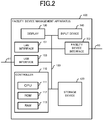
- the hardware configuration of the facility-device management apparatus 100 includes components illustrated in FIG. 2 . That is, the facility-device management apparatus 100 includes a controller 110 that controls overall operations of the facility-device management apparatus 100, a storage device 120 that stores data necessary for the controller 110 operations, a display 130 for providing information necessary for an operator of the facility-device management apparatus 100, and an input device 140 for accepting operation inputs made by the operator. For interfacing with other devices, the facility-device management apparatus 100 further includes a LAN interface 151, a facility device interface 152, and a USB interface 153. Each of the components (controller 110, storage device 120, display 130, input device 140, LAN interface 151, facility device interface 152, and USB interface 153) of the facility-device management apparatus 100 is mutually connected with one another via an internal bus 190.
- the controller 110 includes, for example, a central processing unit (CPU) 111, a read only memory (ROM) 112, and a random access memory (RAM) 113.
- the controller 110 controls the overall operations of the facility-device management apparatus 100 by executing the program stored in the ROM 112 or the RAM 113. As necessary, the controller 110 retrieves data such as a program from the storage device 120, or saves data onto the storage device 120.
- the storage device 120 includes a storage device such as a hard disk drive, flash memory, and/or the like and stores, in accordance with a control of the controller 110, data necessary for running the facility-device management apparatus 100.
- the display 130 includes a display device that is a liquid crystal display, a cathode ray tube, or the like and displays information to be presented to the operator of the facility-device management apparatus 100.
- the input device 140 includes a keyboard, mouse, and/or the like and accepts operation inputs made by the operator and provides the controller 110 with the operation inputs.
- the display 130 presents, to the operator of the facility-device management apparatus 100, information necessary for monitoring and controlling the facility devices.
- the input device 140 accepts operation inputs made by the operator for monitoring and controlling the facility devices and provides the controller 110 with the operation inputs.
- the facility-device management apparatus 100 includes a device, represented by the liquid crystal touch panel, that realizes both the function of displaying a screen and the function of accepting an operation with respect to the screen that is displayed, and this device may provide the function of the display 130 together with the function of the input device 140.
- the LAN interface 151 has a function of connecting the facility-device management apparatus 100 to a LAN that is compliant with protocol such as Ethernet (registered trademark) and TCP/IP.
- the facility-device management apparatus 100 transmits the operation data to the remote monitoring server 300 via the LAN interface 151.
- the facility device interface 152 connects the facility-device management apparatus 100 to the facility device network 90.
- the facility-device management apparatus 100 is connected to each of the facility devices via the facility device network 90 and acquires operation data of each of the facility devices.
- the facility device network 90 may be a general-use LAN configurable using any protocol or may be a network using a specific protocol.
- the USB interface 153 connects the facility-device management apparatus 100 to the relay device 200 via the connection line 91.
- the connection line 91 is a USB standard based general-purpose cable.
- the facility-device management apparatus 100 via the connection line 91, transmits data to the relay device 200 and receives data transmitted by the relay device 200.
- the controller 110 implements the functional components illustrated in FIG 3 , as internal functions of the facility-device management apparatus 100. That is, the controller 110 includes a facility device manager 11 for managing each of the facility devices via the facility device interface 152, a transmission destination setter 12 for setting a transmission destination for the operation data, a server communicator 13 for communicating with the remote monitoring server 300 via the LAN interface 151, and a relay device communicator 14 for communicating with the relay device 200 via the USB interface 153.
- the facility device manager 11 manages each of the facility devices connected via the facility device interface 152 and the facility device network 90 to the facility device manager 11. Specifically, the facility device manager 11, on a cyclical basis, acquires, from each of the facility devices, data indicating the running state (power consumption, running environment (set temperature and airflow strength), and the like) of the corresponding facility device and stores the acquired data as operation data.
- the facility device manager 11 acquires error information transmitted by a facility device when an error occurs in the facility device, and stores the error information as operation data and also stores the error information as operation data.
- facility device manager 11 may acquire data indicating the running state from each of the facility devices based on operation details inputted via the input device 140.
- the facility device manager 11 may also display the operation data on the display 130 based on inputted operation details.
- the transmission destination setter 12 sets the transmission destination for the operation data of the facility-device management apparatus 100.
- the storage device 120 which is described in detail below, stores information indicating the destination of the operation data.
- the server communicator 13 transmits the stored operation data to the remote monitoring server 300 via the LAN interface 151.
- the server communicator 13 includes a data generator 13a that generates TCP/IP protocol-compliant data (first-protocol transmission data) based on the stored operation data, a transmitter 13b that transmits data of the TCP/IP protocol via the LAN interface 151, and a receiver 13c that receives data of the TCP/IP protocol via the LAN interface 151.
- the data generator 13a extracts, from the operation data stored in the storage device 120, data to be reported to the remote monitoring server 300. Any extraction criteria may be used.
- the data generator 13a for example, extracts from the stored operation data, data of a particular period of time including the point of time when extraction processing is performed (for example, a period of time from one week before the point of time of extraction to the point of time of extraction) or data not yet reported to the remote monitoring server 300.
- the data generator 13a generates data (first-protocol transmission data) based on TCP/IP protocol to be transmitted to the remote monitoring server 300 by modifying the data to conform to the format of TCP/IP protocol (affixing a header that conforms to TCP/IP protocol, for example).
- the transmitter 13b transmits data of the TCP/IP protocol via the LAN interface 151. More particularly, the transmitter 13b transmits the data that is generated by the data generator 13a based on the operation data. Further, the receiver 13c receives data of TCP/IP protocol via the LAN interface 151.
- the server communicator 13 Upon the data generator 13a generating the TCP/IP protocol-compliant data that is to be transmitted remote monitoring server 300, the server communicator 13 fetches, from the storage device 120, the information indicating the transmission destination of the operation data set by the transmission destination setter 12. As long as fetched information contains the information indicating the remote monitoring servicer 300 as the transmission destination, the data generated by the data generator 13a is transmitted by the server communicator 13, via the transmitter 13b. Conversely, when the fetched information does not contain the information indicating the remote monitoring server 300 as the transmission destination, the server communicator 13 transmits the data generated by the data generator 13a to the relay device communicator 14.
- the relay device communicator 14 performs communication with the relay device 200 via the USB interface 153 and the connection line 91. More particularly, the relay device communicator 14 receives the data transmitted by the server communicator 13, performs protocol conversion, and then transmits the converted data to the relay device 200. In order to implement these functions, the relay device communicator 14 includes a data converter 14a that converts TCP/IP protocol-compliant data into USB protocol-compliant data and vice versa. The relay device communicator 14 also includes a transmitter 14b that transmits data by USB protocol to the relay device 200 via the USB interface 153 and a receiver 14c that receives data by USB protocol from the relay device 200 via the USB interface 153.
- the data converter 14a receives the data (TCP/IP protocol-compliant data) transmitted by the server communicator 13 and converts the received data into USB protocol format data.
- the data transmitted by the server communicator 13 is TCP/IP protocol-compliant data generated by the data generator 13a.
- the data converter 14a analyzes the received data, and separates, from among the analyzed data, a portion corresponding to the operation data to be transmitted to the remote monitoring server 300 and a portion that is distinctly TCP/IP protocol (TCP/IP protocol header, delimiters and the like).
- the data converter 14a discards the portion that is distinctly TCP/IP protocol, and then adds a header to the portion corresponding to the operation data to be transmitted to the remote monitoring server 300, so as to be data in a USB protocol compliant format. In this manner, the data converter 14a converts the TCP/IP-compliant protocol data into USB protocol-compliant data.
- the transmitter 14b and the receiver 14c communicate with the relay device 200 via the USB interface 153 and the connection line 91 using USB protocol. More particularly, the transmitter 14b transmits to the relay device 200 the data converted by the data converter 14a into USB protocol data. Also, the receiver 14c receives the data transmitted by the relay device 200.
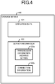
- the facility-device management apparatus 100 stores the data indicated in FIG. 4 into the storage device 120. That is, the storage device 120 stores operation data 121 containing the operation information of the facility device, and stores server information 122 containing the information regarding the remote monitoring server 300 that is the report destination of operation data.
- the operation data 121 is data containing operation information of facility devices managed by the facility-device management apparatus 100.
- the facility-device management apparatus 100 uses the function of the facility device manager 11 to acquire information regarding operation from each of the facility devices and store the acquired information into the operation data 121.
- the operation data 121 contains information of, for example, a facility device regarding the starting of operation and stopping of operation, operation modes (cooling and heating, for example), setting temperature, indoor temperature, and event information indicating when an event, such as an error, occurred, and also contains detail data that is used when performing maintenance on a facility device.
- the facility device manager 11, on a periodic basis or when an event occurs acquires operation-related information from a facility device, and then updates the operation data 121.
- the data generator 13a refers to the operation data 121 to generate report data to be reported to the remote monitoring server 300.
- the server information 122 is data containing information for transmitting report data generated based on the operation data 121 to the remote monitoring server 300 by the facility-device management apparatus 100.
- the server information 122 contains a transmission destination address setting 122a and connection information 122b.
- the transmission destination address setting 122a is data indicating information set as a destination of the report data. For example, when an Internet Protocol (IP) address of the remote monitoring server 300 is contained in the transmission destination address setting 122a, the server communicator 13 transmits data of TCP/IP protocol generated based on the operation data 121, via the LAN interface 151. Also, the data contained in the transmission destination address setting 122a is not limited to IP addresses. A uniform resource locator (URL), indicating the location of the remote monitoring server 300 on the Internet, may be contained in the transmission destination address setting 122a, for example.
- IP Internet Protocol
- URL uniform resource locator
- the server communicator 13 does not transmit report data generated by the data generator 13a to the outside via the LAN interface 151.
- the local loopback address is a type of IP address that indicates the transmission destination is the apparatus itself.
- the server communicator 13 transmits the report data generated by the data generator 13a to the relay device communicator 14 inside the apparatus itself (facility-device management apparatus 100).
- the relay device communicator 14 receives and converts the report data TCP/IP protocol-compliant report data into data of USB protocol-compliant format and then forwards the data by USB protocol to the relay device 200 via the USB interface 153 (and connection line 91). That is, when the local loopback address is contained in the transmission destination address setting 122a, the facility-device management apparatus 100a transmits the report data to the relay device 200 via the USB interface 153, instead of transmitting the report data to the remote monitoring server 300 via the LAN interface 151.
- the facility-device management apparatus 100 includes the previously described transmission destination setter 12 and provides the operator with a way to input data of the transmission destination address setting 122a. That is, the transmission destination setter 12 contains information input by the operator via the input device 140 into the transmission destination address setting 122a.
- the transmission destination setter 12 sets the facility-device management apparatus 100 to transmit the report data to the remote monitoring server 300.
- the transmission destination setter 12 sets the facility-device management apparatus 100 not to transmit the report data to the remote monitoring server 300.
- the transmission destination setter 12 functions as setting means for setting whether or not the facility-device management apparatus 100 is to transmit report data to the remote monitoring server 300. Also, the transmission destination setter 12 may be regarded as selection means for selecting which of the remote monitoring server 300 and the relay device 200 is to be transmitted the report data.
- the connection information 122b is data necessary for transmitting report data to the remote monitoring server 300.
- the connection information 122b contains information necessary for connecting to the remote monitoring server 300, for example, authentication information (username and password) a port number, an application layer protocol such as Hypertext Transfer Protocol (HTTP) or Simple Mail Transfer Protocol (SMTP), and the host name of the facility-device management apparatus 100.
- HTTP Hypertext Transfer Protocol
- SMTP Simple Mail Transfer Protocol
- the transmitter 13b of the server communicator 13 When the transmitter 13b of the server communicator 13 is to transmit the report data to the remote monitoring server 300, the transmitter 13b appropriately refers to the connection information 122b and either adds to the report data any data that is necessary, or transmits the necessary data prior to transmitting the report data.
- the transmitter 14b of the relay device communicator 14 when the transmitter 14b of the relay device communicator 14 is to transmit report data to the relay device 200, the transmitter 14b likewise refers to the connection information 122b and either adds to the report data any data that is necessary, or transmits the necessary data prior to transmitting the report data.
- the hardware configuration of the relay device 200 includes components illustrated in FIG. 5 . That is, the relay device 200 includes a controller 210 that controls overall operations of the relay device 200, a storage device 220 that stores data information necessary for the controller 210 operations, a display 230 for providing information necessary for an operator of the relay device 200, and an input device 240 for accepting operation inputs made by the operator. For interfacing with other devices, the relay device 200 also includes a LAN interface 251 and a USB interface 252. Each of the components (controller 210, storage device 220, display 230, input device 240, LAN interface 251, and USB interface 252) of the relay device 200 is mutually connected with one another via an internal bus 290.
- the controller 210, the display 230, the input device 240, and the internal bus 290 are the same as the identically named hardware components in the facility-device management apparatus 100, and a description thereof is therefore omitted.
- the LAN interface 251 has a function of connecting the relay device 200 to a LAN that is compliant with protocol such as Ethernet (registered trademark) and TCP/IP.
- the relay device 200 transmits report data to the remote monitoring server 300 via the LAN interface 251. Further, the relay device 200 receives data, via the LAN interface 251, from another device connected to the intra-facility LAN 92 or from yet another device connected with the relay device 200 via the Internet 93.
- the USB interface 252 connects the relay device 200 with the facility-device management apparatus 100 via the connection line 91.
- the facility-device management apparatus 100 via the connection line 91, transmits data to the relay device 200 and receives data transmitted by the relay device 200.
- the storage device 220 includes a storage device such as a hard disk drive, flash memory, and/or the like and stores, in accordance with a control of the controller 210, data necessary for running the relay device 200. More particularly, the storage device 220 stores security criteria 221 and a server address setting 222.
- the security criteria 221 contains information indicating what data among the data received by the relay device 200 via the LAN interface 251 may be forwarded to the facility-device management apparatus 100.
- the security criteria may be set such that only acknowledgement data from the remote monitoring server 300 in response to report data transmitted by the relay device 200, via the LAN interface 251, to the remote monitoring server 300 may be forwarded to the facility-device management apparatus 100.
- only data associated with verification of the remote monitoring server 300 may be forwarded to the relay-device management apparatus 100.
- the relay device 200 may use any criteria as the security criteria 221.
- the server address setting 222 is information indicating the location on the Internet of the remote monitoring server 300 that is the destination of the report data.
- the server address setting 222 contains the IP address or the URL of the remote monitoring server 300.
- the controller 210 implements each of the functional components illustrated in FIG. 6 , as the internal functions of the relay device 200. That is, the controller 210 includes a forwarder 21 that converts report data received from the relay device 200 into a TCP protocol format and transmits the data of TCP protocol to the remote monitoring server 300. Further, the controller 210 includes a protector 22 that extracts, from the data received by the LAN interface 251, data (secure data) that meets the security criteria 221, converts the extracted data into the USB protocol format, and then transmits the USB protocol format data via the USB interface 252.
- the forwarder 21 receives report data from the relay device 200 via the USB interface 252. Further, upon receipt of the report data, the forwarder 21 fetches the server address setting 222 of the storage device 220 and acquires the IP address of the remote monitoring server 300. The forwarder 21 converts the received report data (USB protocol format) into TCP/IP protocol format. When doing so, the IP address acquired from the remote monitoring server 300 is added to the portion, indicating the transmission destination IP address, in the header of the report data. The forwarder 21 transmits the report data that is in TCP/IP protocol format to the network via the LAN interface 251. The transmitted report data reaches the remote monitoring server 300 via the intra-facility LAN 92.
- the protector 22 extracts the data (secure data) that meets the security criteria 221 from the data received by the LAN interface 251 and transmits the extracted data to the facility-device management apparatus 100 via the USB interface 252.
- the security criteria 221 is set such that only acknowledgement data from the remote monitoring server 300, in response to report data transmitted by the relay device 200, may be forwarded to the remote monitoring server 300
- the protector 22 transmits, via the USB interface 252, data received only when the received data is acknowledgement data from the remote monitoring server 300.
- the protector 22 fetches the data from the storage device 220 when, for example, the relay device 200 is powered on.
- the protector 22 Upon receipt of data via the LAN interface 251, the protector 22 extracts data that meets the fetched secure data criteria and transmits the extracted data via the USB interface 252 to the facility-device management apparatus 100.
- the control system 1 transmits, to the remote monitoring server 300, the report data (first protocol data) generated based on the operation data acquired from the facility device .
- the relay device 200 that includes the protector 22 extracts data that meets the security criteria 221 and transmits the extracted data to the facility-device management apparatus 100. Since the facility-device management apparatus 100 is not directly connected to the Internet 93 and only receives data extracted in the relay device 200, a high security level can be easily maintained.
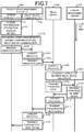
- FIG. 7 is a diagram illustrating the flow of data occurring when the facility-device management apparatus 100 reports operation data to the remote monitoring server 300 via the relay device 200.
- the transmission destination address setting 122a of the facility-device management apparatus 100 contains data indicating the local loopback address. That is, for the case indicated in FIG. 7 , the facility-device management apparatus 100 is set not to transmit the first protocol report data to the remote monitoring server 300.
- the facility-device management apparatus 100 When an event (such as arrival of a transmission deadline, an operation input by the operator requesting transmission of report data, or detection of an error) setting for report data to be generated occurs, the facility-device management apparatus 100 generates, based on the operation data 121, report data (first protocol data) that is to be reported to the remote monitoring server 300. The facility-device management apparatus 100 transmits the operation data to the remote monitoring server 300 via the relay device 200 in accordance with the data flow illustrated in FIG. 7 .
- report data first protocol data
- the server communicator 13 of the facility-device management apparatus 100 acquires the transmission destination address setting (step S101).
- the server communicator 13 refers to the transmission address setting 122a in the storage device 120 and acquires information (in this case, the local loopback address) indicating the transmission destination of the report data.
- the server communicator 13 establishes a connection with the relay device communicator 14 (step S102). Since the acquired information indicating the transmission destination of the report data is information indicating the apparatus itself (that is, the relay device communicator 14), the server communicator 13 transmits, to the relay device communicator 14 in the apparatus itself, a signal indicating connection request. The relay device communicator 14 acknowledges the received signal indicating connection request and transmits a signal indicating connection permission. The server communicator 13 establishes connection with the relay device communicator 14 upon completion of this process.
- the server communicator 13 transmits the operation data to the relay device communicator 14 (step S103).
- the server communicator 13 transmits report data generated based on TCP/IP protocol to the relay device communicator 14.
- the relay device communicator 14 performs protocol conversion on the received report data (step S104).
- the relay device communicator 14 extracts, from the report data that is TCP/IP protocol format, the data corresponding to the operation data.
- the relay device communicator 14 modifies (affixes a proper header, for example) the extracted data such that the data conforms to USB protocol.
- the relay device communicator 14 transmits the operation data that is in a format compliant with USB protocol to the relay device 200 via the connection line 91 (step S105).
- the relay device 200 Upon receipt of the operation data, the relay device 200 performs protocol conversion on the received operation data (step S106).
- the relay device 200 modifies (deletes the USB protocol header and affixes the proper header) the USB protocol-compliant formatted operation data (second-protocol transmission data) to conform to TCP/IP protocol.
- the relay device 200 also fetches the server address setting 222 from the storage device 220 and inserts the server address setting 222 into the transmission destination address of the TCP/IP header.
- the relay device 200 establishes connection with the remote monitoring server 300 (step S107).
- the relay device 200 fetches the server address setting 222 from the storage device 220 and acquires information indicating the location of the remote monitoring server 300 on the Internet.
- the relay device 200 transmits, based on the acquired information, a signal indicating a connection request, to the remote monitoring server 300.
- the remote monitoring server 300 acknowledges the received signal indicating a connection request and transmits a signal indicating connection permission.
- the relay device 200 establishes connection with the remote monitoring server 300.
- the relay device 200 transmits, to the remote monitoring server 300, the operation data converted into a format that conforms to TCP/IP protocol (step S108).
- the remote monitoring server 300 having received the operation data from the relay device 200 transmits an acknowledgement signal in response to the received operation data (step S109).
- the relay device 200 Upon receipt of the acknowledgement signal from the remote monitoring server 300, the relay device 200 performs protocol conversion on the acknowledgement signal (step S110). The relay device 200 converts the acknowledgement signal from TCP/IP protocol format to USB protocol format.
- the relay device 200 transmits the acknowledgement signal converted into USB protocol to the relay device communicator 14 of the facility-device management apparatus 100 via the connection line 91 (step S111).
- the relay device communicator 14 Upon receipt of the acknowledgement signal from the relay device 200, the relay device communicator 14 performs protocol conversion on the acknowledgement signal (step S112). The relay device communicator 14 converts the received acknowledgement signal from USB protocol format to TCP/IP protocol format.
- the relay device communicator 14 transmits, to the server communicator 13, the acknowledgement signal converted into TCP/IP protocol format (step S113).
- the server communicator 13 transmits, to the remote monitoring server 300, the report data (first-protocol transmission data) generated based on the operation data and receives the acknowledgement signal from the remote monitoring server 300. That is, the control system 1 reports the report data generated based on the operation data to the remote monitoring server 300 by performing this processing.
- the server communicator 13 performs a process corresponding to the aforementioned steps S101 to S103 and step S113. That is, the server communicator 13, in this case, acquires the IP address or URL of the remote monitoring server 300 from the transmission destination address setting 122a (corresponding to step S101), establishes connection with the remote monitoring server 300 (corresponding to step S102), and transmits the report data to the remote monitoring server 300 (corresponding to step S103). Upon receipt of the transmitted report data, the remote monitoring server 300 transmits an acknowledgement signal to the server communicator 13 (corresponding to step S113).
- the server communicator 13 When the transmission destination address setting 122a contains information (IP address or URL) indicating the location of the remote monitoring server 300 on the Internet (that is, when a setting is made to transmit report data by TCP/IP protocol to the remote monitoring server 300), the server communicator 13 transmits the report data via the LAN interface 151 to the remote monitoring server 300. Conversely, when the transmission destination address setting 122a contains a local loopback address (that is, when a setting is made not to transmit the report data by TCP/IP protocol to the remote monitoring server 300), the server communicator 13 transmits the report data to the relay device communicator 14. The relay device communicator 14 converts the received report data received in TCP/IP protocol into report data compliant with USB protocol, and transmits the report data by USB protocol to the relay device 200 via the USB interface 153.
- any protocol may be used in the application layer.
- acceptable protocols include Hypertext Transfer Protocol (HTTP), Simple Mail Transfer Protocol (SMTP), and File Transfer Protocol (FTP).
- HTTP Hypertext Transfer Protocol
- SMTP Simple Mail Transfer Protocol
- FTP File Transfer Protocol
- the control system 1 according to the present background example may implement a protocol that uses User Datagram Protocol (UDP) instead of TCP.
- UDP User Datagram Protocol
- the transmission destination setter 12 adds, to the transmission destination address setting 122a, the content inputted via the input device 140 by the operator of the facility-device management apparatus 100, and thereby sets whether or not the facility-device management apparatus 100 is to transmit the report data to the remote monitoring server 300.
- the transmission destination setter 12 may instead determine whether the LAN interface 151 of the facility-device management apparatus 100 is connectable or not-connectable to the remote monitoring server 300, and when determining that connection is not possible, the transmission destination setter 12 may set such that the facility-device management apparatus 100 does not transmit the report data to the remote monitoring server 300.
- the facility-device management apparatus 100 in addition to the transmission destination address setting 122a, the facility-device management apparatus 100 also stores, into the storage device 120, direct transmission flag data indicating whether or not the facility-device management apparatus 100 is to transmit the report data to the remote monitoring server 300.
- the transmission destination setter 12 also stores the IP address or the URL of the remote monitoring server 300 into the transmission destination address setter 122a.
- the transmission destination setter 12 verifies connectivity with the remote monitoring server 300 via the LAN interface 151. Specifically, the transmission destination setter 12 issues a type of command called ping-command to the IP address stored in the transmission destination address setting 122a.
- the transmission destination setter 12 When an arrival acknowledgement in response to the issued ping-command is returned from the destination address, the transmission destination setter 12 sets the direct transmission flag data to ON. Conversely, if an arrival acknowledgement is not returned from the destination address in response to the ping-command within a given time period, the transmission destination setter 12 sets the direct transmission flag data to OFF.
- the server communication 13 After generating the report data, the server communication 13 refers to the direct transmission flag data and determines whether or not the facility-device management apparatus 100 is to transmit the report data to the remote monitoring server 300. When the direct transmission flag data is set as ON, the server communicator 13 transmits the report data via the LAN interface 151. Conversely, when the direct transmission flag data is set as OFF, the server communicator 13 transmits the report data to the relay device communicator 14.
- the transmission destination setter 12 stores, into the storage 120, information indicating whether or not the facility-device management apparatus 100 is to transmit the report data to the remote monitoring server 300.
- the transmission destination setter 12 may include a physical switch that may be toggled between ON and OFF to switch between a transmission and a non-transmission of the report data to the remote monitoring server 300.
- the operator of the facility-device management apparatus 100 for example, can toggle the switch to switch between transmission via the relay device 200 and transmission via the LAN interface 151, of the report data.
- the relay device 200 that ensures security connects to the network (intra-facility LAN 92) connected to the Internet, whereas the facility-device management apparatus 100 does not connect directly to the intra-facility LAN 92.
- Using the control system 1 according to the present background example therefore can reduce the risk of the facility-device management apparatus 100 being attacked directly by an unauthorized user from an external device.
- connection line 91 is a USB protocol dedicated connector that makes hacking into communications between the facility-device management apparatus 100 and the relay device 200 difficult from another device. Therefore, a high security level can be maintained in the network (connection line 91, facility-device management apparatus 100, and facility device network 90, and each facility device) beyond the relay device 200.
- the facility-device management apparatus 100 does not have an IP address in the intra-facility LAN 92. Therefore, replacing the facility-device management apparatus 100 does not result in extra work for the network administrator of the intra-facility LAN 92, thereby reducing the administration workload.
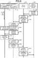
- Embodiment 1 In the background example, an example is described in which the control system 1, triggered by the occurrence of an internal event (such as arrival of a transmission deadline, an operation input by an operator, or occurrence of an event, for example), generates report data and transmits the report data to the remote monitoring server 300. However, the control system 1 may generate report data in response to a request from the remote monitoring server 300 instead and transmit the report data to the remote monitoring server 300. In an embodiment of the invention, an example is described in which the control system 1 transmits report data in response to a request from remote monitoring server 300.
- an internal event such as arrival of a transmission deadline, an operation input by an operator, or occurrence of an event, for example
- the relay device 200 receives the transmitted request command.
- the relay device 200 refers to the security criteria 221 and when the received request command meets the security criteria 221, the relay device 200 performs protocol conversion on the received request command (step S202).
- the relay device 200 converts the received request command from TCP/IP protocol format to USB protocol format.
- the relay device 200 transmits the request command converted into USB protocol format to the relay device communicator 14 via the connection line 91 (step S203).
- the relay device communicator 14 Upon receipt of the request command, the relay device communicator 14 performs protocol conversion on the received request command (step S204). The relay device communicator 14 converts the received request command from USB protocol format into TCP/IP protocol format.
- the relay device communicator 14 establishes connection with the server communicator 13 (step S205).
- the relay device communicator 14 transmits to the server communicator 13 a signal indicating a connection request.
- the server communicator 13 acknowledges the received signal indicating the connection request and transmits a signal indicating connection permission.
- the relay device communicator 14 establishes connection with the server communicator 13.
- the relay device communicator 14 transmits the request command converted into TCP/IP protocol format to the server communicator 13 (step S206).
- the server communicator 13 receives the request command, generates operation data in accordance with the request command, and transmits the operation data to the relay device communicator 14 (step S207).
- the server communicator 13 analyzes the received request command and determines the kind of data the remote monitoring server 300 is requesting to be extracted based on the operation data 121 and transmitted.
- the server communicator 13 generates, based on the operation data 121, operation data in accordance with the request command and generates TCP/IP protocol operation data.
- the server communicator 13 transmits the generated operation data to the relay device communicator 14.
- the relay device communicator 14 Upon receipt of the operation data, the relay device communicator 14 performs protocol conversion on the received operation data (step S208). The relay device communicator 14 converts the received operation data from TCP/IP protocol format to USB protocol format.
- the relay device communicator 14 transmits the operation data converted into USB protocol format to the relay device 200 via the connection line 91 (step S209).
- the relay device 200 Upon receipt of the operation data, the relay device 200 performs protocol conversion on the received operation data (step S210). The relay device 200 converts the received operation data from USB protocol format into TCP/IP protocol format.
- the relay device 200 transmits the operation data converted into TCP/IP protocol format to the remote monitoring servicer 300 (step S211). Through this process, the operation data requested by the remote monitoring server 300 is transmitted from the control system 1 to the remote monitoring server 300.
- the relay device 200 extracts, from the data received via the LAN interface 251, secure data that meets the security criteria 221 and transmits the extracted secure data to the facility-device management apparatus 100. This enables the facility-device management apparatus 100 to be protected from outside threats.
- the relay device 200 includes a function to appropriately accept request commands from the outside.
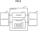
- the controller 210 of the relay device 200 according to Embodiment 1 implements a web server functioner 22a as a portion of the protector 22 as indicated in FIG. 9 .
- the web server functioner 22a communicates with the web browser running on another device (remote monitoring server 300) and accepts a request command directed to the facility-device management apparatus 100.
- the web server functioner 22a extracts, from the received request command, the secure data that meets the security criteria 221 and transmits the extracted secure data to the facility-device management apparatus 100.
- the inclusion of the web server functioner 22a within the protector 22 enables, for example, easy implementation of a security framework used by a common web server.
- an existing web server already includes username and password-based authentication system.
- the web server functioner 22a By implementing a username and password-based authentication system with the web server functioner 22a, any request command without a correct username and password is discarded, thereby protecting the facility-device management apparatus 100.
- the correct username and password are stored as a set in the security criteria 221.
- common web servers can communicate information not only with other devices via a network but also through a web browser running on a device itself.
- setting the web server functioner 22a to communicate with a web browser running by the device itself (relay device 200) enables not the remote monitoring server 300 but rather the relay device 200 to acquire operation data.
- the operator of the relay device 200 can conveniently confirm the operation data of each facility device, via the display 130 provided by the relay device 200.
- connection line 91 is a USB-based cable connection.
- any universal standard-based connection can be used as the connection line 91.
- acceptable connections may include Institute of Electrical and Electronics Engineers (IEEE)-based connections 1394, Recommended Standard (RS) 232C-based connections, and Bluetooth (registered trademark)-based connections.
- IEEE Institute of Electrical and Electronics Engineers
- RS Recommended Standard
- Bluetooth registered trademark
- the remote monitoring server 300 receives operation data transmitted by the relay device 200.
- a proxy server may be installed between the relay device 200 and the remote monitoring server 300.
- the relay device 200 transmits operation data to the proxy server and the proxy server transmits the received operation data to the remote monitoring server 300.
- the programs executed by the facility-device management apparatus 100 or the relay device 200 in the aforementioned embodiments may be stored in a computer-readable recording medium such as a compact disk read-only memory (CD-ROM), a digital versatile disc (DVD), a magneto-optical disk (MO), a universal serial bus (USB) memory and a memory card and distributed
- a computer-readable recording medium such as a compact disk read-only memory (CD-ROM), a digital versatile disc (DVD), a magneto-optical disk (MO), a universal serial bus (USB) memory and a memory card and distributed
- CD-ROM compact disk read-only memory
- DVD digital versatile disc
- MO magneto-optical disk
- USB universal serial bus
- the above-described program may be stored on a storage device of a server device on a communication network, such as the Internet, to enable the program to be downloaded to the computer, for example by superimposing the program onto a carrier wave.
- the above-described processing can be achieved even by execution while the program is transferred through the communication network.
- the above-described processing can be achieved by executing all or part of the program on the server device, and executing the program while sending and receiving by the computer the information relating to such processing through the communication network.
- the non-OS portion alone may be stored in the above-described recording medium and distributed, or alternatively, may be, for example, downloaded to the computer.
- the present disclosure is suitable for a control system for reporting operation data of facility devices installed in a facility such as a building.
Description
- The present disclosure relates to a control system and a facility-device management apparatus.
- Technology for managing, via a network, facility devices such as air conditioners and lighting is becoming more widespread. In particular, in some buildings with numerous facility devices, the facility devices installed are monitored by a terminal connected, via a network, to the facility devices.
- For example, in Patent Literature, 1 discloses a configuration of facility management apparatus for collecting data of air-conditioning equipment and periodically transmitting the data, via a network, to a server computer in a remote location.
-
- Patent Literature 1: Unexamined Japanese Patent Application Kokai Publication
2005-17815 - Patent Literature 2 :
US 2006/031457 - Patent Literature 3 :
US 2005/246408 - However, conventional technology poses a problem in that, work performed to establish a configuration for communicating data over a network while ensuring security, is costly.
- Network-connected devices present an ever-increasing security risk as information technology continues to advance. Therefore, an administrator often imposes security restrictions on a system and network as he/she sees fit in order to protect devices and information from the threat of external unauthorized access.
- In the case of a network managed with a high-security standard, when a facility device is newly installed, the device must be configured so that the settings are in compliance with the security standard. This requires a worker having sufficient knowledge of security to spend time and effort configuring facility devices to be security-standard compliant, consequently increasing work-related costs.
- In order to solve the aforementioned problem, an objective of the present disclosure is to provide an easily implementable configuration that enables monitoring of facility devices via a network while ensuring security.
- In order to achieve the aforementioned objective, a control system of the present disclosure is a system for transmitting to a remote monitoring server, first-protocol transmission data generated based on operation data acquired from a facility device. The control system includes a facility-device management apparatus according to claim 1 configured to generate the first-protocol transmission data based on the operation data; and a relay device configured to communicate with the remote monitoring server via a network configured based on a first protocol, the relay device further configured to communicate with the facility-device management apparatus via a connection configured based on a second protocol. The facility-device management apparatus includes setting means for setting whether or not to transmit the first-protocol transmission data to the remote monitoring server; first transmission means for transmitting, when the first-protocol transmission data is set to be transmitted to the remote monitoring server, the first-protocol transmission data to the remote monitoring server; and second transmission means for, when the first-protocol transmission data is set not to be transmitted to the remote monitoring server, converting the first-protocol transmission data into second-protocol transmission data, and transmitting the second-protocol transmission data to the relay device. The relay device includes forwarding means for receiving the second-protocol transmission data from the facility-device management apparatus, converting the second-protocol transmission data into the first-protocol transmission data, and transmitting the first-protocol transmission data to the network.
- The present disclosure provides an easily implementable configuration that enables monitoring of facility devices via a network while ensuring security.
-
-
FIG. 1 is a schematic diagram illustrating a control system according to Embodiment 1; -
FIG. 2 is a block diagram illustrating hardware a configuration of a facility-device management apparatus; -
FIG. 3 is a block diagram illustrating a functional configuration implemented by a controller of the facility-device management apparatus; -
FIG. 4 is a diagram illustrating data content stored in the storage device; -
FIG. 5 is a block diagram illustrating a hardware configuration of a relay device; -
FIG. 6 is a block diagram illustrating a function configuration to be implemented by a controller of the relay device according to Embodiment 1; -
FIG. 7 is a diagram illustrating a data flow example occurring when the control system transmits operation data to a remote monitoring server; -
FIG. 8 is a diagram illustrating another data flow example occurring when the control system transmits operation data to the remote monitoring server; and -
FIG. 9 is a block diagram illustrating a function configuration implemented by the controller of relay device according to Modified Embodiment 1. - The embodiments of the present disclosure are described in detail below with reference to the drawings. However the same reference signs are used for the same parts throughout the drawings. The terms "up", "down", "left", and "right" are used in the below description with respect to the drawings. These terms are used merely to facilitate understanding and in no way limit the scope of the present disclosure.
- Background Example A control system 1 of the present background example, as illustrated in
FIG. 1 , includes a facility-device management apparatus 100 for managing facility devices (facility devices relay device 200 that is connected to the facility-device management apparatus 100. The facility-device management apparatus 100 acquires, from each of the facility devices (facility devices device management apparatus 100 periodically reports the stored operation data to aremote monitoring server 300. Therelay 200 receives the operation data from the facility-device management apparatus 100 and then transmits the received operation data to theremote monitoring server 300 to which the operation data is to be reported. - The facility-
device management apparatus 100 is connected, via afacility device network 90, with each of the facility devices (facility devices facility 3, and transmits and receives data to and from each of the facility devices via thefacility device network 90. More particularly, the facility-device management apparatus 100 acquires, from each of the facility devices, data indicating the running state of the corresponding facility device, and then stores the data as the operation data. The operation data contains, for example, information regarding power consumption, running environment (set temperature and airflow strength) and error events that occurred, in the targeted facility device. Thefacility device network 90 may be configured in accordance with any standard, for example by a general-purpose wired network such as a wired local area network (LAN) and/or by a dedicated line. - The facility device (
facility devices device management apparatus 100 is installed in a room or a facility and is used as needed. Examples of facility devices include air conditioners, lighting, and room-entry management devices. However, the facility device is not restricted to these examples. The present background example is applicable to any kind of facility device. The example inFIG. 1 explicitly indicates that threefacility devices device management apparatus 100. However, there is no limit to the number of the facility devices that may be connected to facility-device management apparatus 100. That is, any number of the facility devices may be connected to the facility-device management apparatus 100. - The facility-
device management apparatus 100 is connected to therelay device 200 by aconnection line 91. Theconnection line 91 that is configured by a cable connection utilizing Universal Serial Bus (USB) protocol is described as an example in the present background example. - The
relay device 200 is connected to the facility-device management apparatus 100 via theconnection line 91, and data may be transmitted and received between both of the device and the apparatus. Further, therelay device 200 is connected to anintra-facility LAN 92. Theintra-facility LAN 92 is a LAN in conformity to a protocol such as Ethernet (registered trademark) and Transmission Control Protocol and Internet Protocol (TCP/IP), and is connected to the Internet 93. Therelay device 200 is connected, via theintra-facility LAN 92, to the Internet 93 and communicates with an external device connected to another LAN that is connected to the Internet. - The
remote monitoring server 300 is a computer device that receives, from the facility-device management apparatus 100, the operation data stored therein. Theremote monitoring server 300 is connected to the Internet 93 via aserver LAN 94. Theremote monitoring server 300, by way of theLAN 94, the Internet 93, and theintra-facility LAN 92, receives the operation data transmitted by therelay device 200 and transmits any necessary data (instructions requesting operation data, for example) to therelay device 200. - The facility-
device management apparatus 100 has a function to transmit operation data to theremote monitoring server 300 via theintra-facility LAN 92 when the facility-device management apparatus 100 is directly connected to theintra-facility LAN 92. In other words, the facility-device management apparatus 100 is capable of generating, based on the operation data, LAN protocol-based data (first-protocol transmission data) to be transmitted to theremote monitoring server 300, and transmitting the LAN protocol-based data to theremote monitoring server 300. However, when a network (Internet 93) connectable to the outside exists between theremote monitoring server 300 and the facility-device management apparatus 100, conceivably, the facility-device management apparatus 100 might become exposed to a threat via the network. Therefore, in the present background example, the facility-device management apparatus 100, as illustrated inFIG. 1 , is not directly connected to theintra-facility LAN 92. The facility-device management apparatus 100, via therelay device 200, is indirectly connected to theintra-facility LAN 92 and performs data communication with theremote monitoring server 300 via therelay device 200. - The
relay device 200 transfers, to theremote monitoring server 300, data received from the facility-device management apparatus 100 via theconnection line 91. Here, the connection line 91 (connection in accordance with the USB standard regulated protocol) and the intra-facility LAN 92 (connection in accordance with Ethernet (registered trademark) regulated protocol) do not use the same protocol. Therefore, during transferring, therelay device 200 converts the data (second-protocol transmission data) received from the facility-device management apparatus 100 via theconnection line 91 into data (first-protocol transmission data) in conformity to the protocol of theintra-facility LAN 92, and transmits the converted data to theremote monitoring server 300 via theintra-facility LAN 92. - The hardware configuration of the facility-
device management apparatus 100 includes components illustrated inFIG. 2 . That is, the facility-device management apparatus 100 includes acontroller 110 that controls overall operations of the facility-device management apparatus 100, astorage device 120 that stores data necessary for thecontroller 110 operations, adisplay 130 for providing information necessary for an operator of the facility-device management apparatus 100, and aninput device 140 for accepting operation inputs made by the operator. For interfacing with other devices, the facility-device management apparatus 100 further includes aLAN interface 151, afacility device interface 152, and aUSB interface 153. Each of the components (controller 110,storage device 120,display 130,input device 140,LAN interface 151,facility device interface 152, and USB interface 153) of the facility-device management apparatus 100 is mutually connected with one another via aninternal bus 190. - The
controller 110 includes, for example, a central processing unit (CPU) 111, a read only memory (ROM) 112, and a random access memory (RAM) 113. Thecontroller 110 controls the overall operations of the facility-device management apparatus 100 by executing the program stored in theROM 112 or theRAM 113. As necessary, thecontroller 110 retrieves data such as a program from thestorage device 120, or saves data onto thestorage device 120. - The
storage device 120 includes a storage device such as a hard disk drive, flash memory, and/or the like and stores, in accordance with a control of thecontroller 110, data necessary for running the facility-device management apparatus 100. - The
display 130 includes a display device that is a liquid crystal display, a cathode ray tube, or the like and displays information to be presented to the operator of the facility-device management apparatus 100. Also, theinput device 140 includes a keyboard, mouse, and/or the like and accepts operation inputs made by the operator and provides thecontroller 110 with the operation inputs. For example, thedisplay 130 presents, to the operator of the facility-device management apparatus 100, information necessary for monitoring and controlling the facility devices. Also, theinput device 140 accepts operation inputs made by the operator for monitoring and controlling the facility devices and provides thecontroller 110 with the operation inputs. - The facility-
device management apparatus 100 includes a device, represented by the liquid crystal touch panel, that realizes both the function of displaying a screen and the function of accepting an operation with respect to the screen that is displayed, and this device may provide the function of thedisplay 130 together with the function of theinput device 140. - The
LAN interface 151 has a function of connecting the facility-device management apparatus 100 to a LAN that is compliant with protocol such as Ethernet (registered trademark) and TCP/IP. The facility-device management apparatus 100 transmits the operation data to theremote monitoring server 300 via theLAN interface 151. - The
facility device interface 152 connects the facility-device management apparatus 100 to thefacility device network 90. The facility-device management apparatus 100 is connected to each of the facility devices via thefacility device network 90 and acquires operation data of each of the facility devices. Thefacility device network 90 may be a general-use LAN configurable using any protocol or may be a network using a specific protocol. - The
USB interface 153 connects the facility-device management apparatus 100 to therelay device 200 via theconnection line 91. Theconnection line 91 is a USB standard based general-purpose cable. The facility-device management apparatus 100, via theconnection line 91, transmits data to therelay device 200 and receives data transmitted by therelay device 200. - The
controller 110 implements the functional components illustrated inFIG 3 , as internal functions of the facility-device management apparatus 100. That is, thecontroller 110 includes afacility device manager 11 for managing each of the facility devices via thefacility device interface 152, atransmission destination setter 12 for setting a transmission destination for the operation data, aserver communicator 13 for communicating with theremote monitoring server 300 via theLAN interface 151, and arelay device communicator 14 for communicating with therelay device 200 via theUSB interface 153. - The
facility device manager 11 manages each of the facility devices connected via thefacility device interface 152 and thefacility device network 90 to thefacility device manager 11. Specifically, thefacility device manager 11, on a cyclical basis, acquires, from each of the facility devices, data indicating the running state (power consumption, running environment (set temperature and airflow strength), and the like) of the corresponding facility device and stores the acquired data as operation data. Thefacility device manager 11 acquires error information transmitted by a facility device when an error occurs in the facility device, and stores the error information as operation data and also stores the error information as operation data. Also,facility device manager 11 may acquire data indicating the running state from each of the facility devices based on operation details inputted via theinput device 140. Thefacility device manager 11 may also display the operation data on thedisplay 130 based on inputted operation details. - The
transmission destination setter 12 sets the transmission destination for the operation data of the facility-device management apparatus 100. Specifically, thestorage device 120, which is described in detail below, stores information indicating the destination of the operation data. - The
server communicator 13 transmits the stored operation data to theremote monitoring server 300 via theLAN interface 151. Specifically, theserver communicator 13 includes adata generator 13a that generates TCP/IP protocol-compliant data (first-protocol transmission data) based on the stored operation data, atransmitter 13b that transmits data of the TCP/IP protocol via theLAN interface 151, and areceiver 13c that receives data of the TCP/IP protocol via theLAN interface 151. - The
data generator 13a extracts, from the operation data stored in thestorage device 120, data to be reported to theremote monitoring server 300. Any extraction criteria may be used. Thedata generator 13a, for example, extracts from the stored operation data, data of a particular period of time including the point of time when extraction processing is performed (for example, a period of time from one week before the point of time of extraction to the point of time of extraction) or data not yet reported to theremote monitoring server 300. Thedata generator 13a generates data (first-protocol transmission data) based on TCP/IP protocol to be transmitted to theremote monitoring server 300 by modifying the data to conform to the format of TCP/IP protocol (affixing a header that conforms to TCP/IP protocol, for example). - The
transmitter 13b transmits data of the TCP/IP protocol via theLAN interface 151. More particularly, thetransmitter 13b transmits the data that is generated by thedata generator 13a based on the operation data. Further, thereceiver 13c receives data of TCP/IP protocol via theLAN interface 151. - Upon the
data generator 13a generating the TCP/IP protocol-compliant data that is to be transmittedremote monitoring server 300, theserver communicator 13 fetches, from thestorage device 120, the information indicating the transmission destination of the operation data set by thetransmission destination setter 12. As long as fetched information contains the information indicating theremote monitoring servicer 300 as the transmission destination, the data generated by thedata generator 13a is transmitted by theserver communicator 13, via thetransmitter 13b. Conversely, when the fetched information does not contain the information indicating theremote monitoring server 300 as the transmission destination, theserver communicator 13 transmits the data generated by thedata generator 13a to therelay device communicator 14. - The
relay device communicator 14 performs communication with therelay device 200 via theUSB interface 153 and theconnection line 91. More particularly, therelay device communicator 14 receives the data transmitted by theserver communicator 13, performs protocol conversion, and then transmits the converted data to therelay device 200. In order to implement these functions, therelay device communicator 14 includes adata converter 14a that converts TCP/IP protocol-compliant data into USB protocol-compliant data and vice versa. Therelay device communicator 14 also includes atransmitter 14b that transmits data by USB protocol to therelay device 200 via theUSB interface 153 and areceiver 14c that receives data by USB protocol from therelay device 200 via theUSB interface 153. - The
data converter 14a receives the data (TCP/IP protocol-compliant data) transmitted by theserver communicator 13 and converts the received data into USB protocol format data. The data transmitted by theserver communicator 13 is TCP/IP protocol-compliant data generated by thedata generator 13a. Thedata converter 14a analyzes the received data, and separates, from among the analyzed data, a portion corresponding to the operation data to be transmitted to theremote monitoring server 300 and a portion that is distinctly TCP/IP protocol (TCP/IP protocol header, delimiters and the like). From the received data, thedata converter 14a discards the portion that is distinctly TCP/IP protocol, and then adds a header to the portion corresponding to the operation data to be transmitted to theremote monitoring server 300, so as to be data in a USB protocol compliant format. In this manner, thedata converter 14a converts the TCP/IP-compliant protocol data into USB protocol-compliant data. - The
transmitter 14b and thereceiver 14c communicate with therelay device 200 via theUSB interface 153 and theconnection line 91 using USB protocol. More particularly, thetransmitter 14b transmits to therelay device 200 the data converted by thedata converter 14a into USB protocol data. Also, thereceiver 14c receives the data transmitted by therelay device 200. - The facility-
device management apparatus 100 stores the data indicated inFIG. 4 into thestorage device 120. That is, thestorage device 120stores operation data 121 containing the operation information of the facility device, and storesserver information 122 containing the information regarding theremote monitoring server 300 that is the report destination of operation data. - The
operation data 121 is data containing operation information of facility devices managed by the facility-device management apparatus 100. The facility-device management apparatus 100 uses the function of thefacility device manager 11 to acquire information regarding operation from each of the facility devices and store the acquired information into theoperation data 121. Theoperation data 121 contains information of, for example, a facility device regarding the starting of operation and stopping of operation, operation modes (cooling and heating, for example), setting temperature, indoor temperature, and event information indicating when an event, such as an error, occurred, and also contains detail data that is used when performing maintenance on a facility device. Thefacility device manager 11, on a periodic basis or when an event occurs, acquires operation-related information from a facility device, and then updates theoperation data 121. Also, thedata generator 13a refers to theoperation data 121 to generate report data to be reported to theremote monitoring server 300. - The
server information 122 is data containing information for transmitting report data generated based on theoperation data 121 to theremote monitoring server 300 by the facility-device management apparatus 100. Theserver information 122 contains a transmission destination address setting 122a andconnection information 122b. - The transmission destination address setting 122a is data indicating information set as a destination of the report data. For example, when an Internet Protocol (IP) address of the
remote monitoring server 300 is contained in the transmission destination address setting 122a, theserver communicator 13 transmits data of TCP/IP protocol generated based on theoperation data 121, via theLAN interface 151. Also, the data contained in the transmission destination address setting 122a is not limited to IP addresses. A uniform resource locator (URL), indicating the location of theremote monitoring server 300 on the Internet, may be contained in the transmission destination address setting 122a, for example. - Also, when a local loopback address that is different from the IP address of the
remote monitoring server 300 is contained in the transmission address setting 122a, theserver communicator 13 does not transmit report data generated by thedata generator 13a to the outside via theLAN interface 151. The local loopback address is a type of IP address that indicates the transmission destination is the apparatus itself. When the local loopback address is contained in the transmission destination address setting 122a, theserver communicator 13 transmits the report data generated by thedata generator 13a to therelay device communicator 14 inside the apparatus itself (facility-device management apparatus 100). Therelay device communicator 14 receives and converts the report data TCP/IP protocol-compliant report data into data of USB protocol-compliant format and then forwards the data by USB protocol to therelay device 200 via the USB interface 153 (and connection line 91). That is, when the local loopback address is contained in the transmission destination address setting 122a, the facility-device management apparatus 100a transmits the report data to therelay device 200 via theUSB interface 153, instead of transmitting the report data to theremote monitoring server 300 via theLAN interface 151. - The facility-
device management apparatus 100 includes the previously describedtransmission destination setter 12 and provides the operator with a way to input data of the transmission destination address setting 122a. That is, thetransmission destination setter 12 contains information input by the operator via theinput device 140 into the transmission destination address setting 122a. When the operator inputs data (IP address or URL of the remote monitoring server 300) directly indicating the location of theremote monitoring server 300 on the Internet, thetransmission destination setter 12 sets the facility-device management apparatus 100 to transmit the report data to theremote monitoring server 300. Conversely, when the operator inputs the local loopback address, thetransmission destination setter 12 sets the facility-device management apparatus 100 not to transmit the report data to theremote monitoring server 300. That is, thetransmission destination setter 12 functions as setting means for setting whether or not the facility-device management apparatus 100 is to transmit report data to theremote monitoring server 300. Also, thetransmission destination setter 12 may be regarded as selection means for selecting which of theremote monitoring server 300 and therelay device 200 is to be transmitted the report data. - The
connection information 122b is data necessary for transmitting report data to theremote monitoring server 300. Theconnection information 122b contains information necessary for connecting to theremote monitoring server 300, for example, authentication information (username and password) a port number, an application layer protocol such as Hypertext Transfer Protocol (HTTP) or Simple Mail Transfer Protocol (SMTP), and the host name of the facility-device management apparatus 100. When thetransmitter 13b of theserver communicator 13 is to transmit the report data to theremote monitoring server 300, thetransmitter 13b appropriately refers to theconnection information 122b and either adds to the report data any data that is necessary, or transmits the necessary data prior to transmitting the report data. Also, when thetransmitter 14b of therelay device communicator 14 is to transmit report data to therelay device 200, thetransmitter 14b likewise refers to theconnection information 122b and either adds to the report data any data that is necessary, or transmits the necessary data prior to transmitting the report data. - The hardware configuration of the
relay device 200 includes components illustrated inFIG. 5 . That is, therelay device 200 includes acontroller 210 that controls overall operations of therelay device 200, astorage device 220 that stores data information necessary for thecontroller 210 operations, adisplay 230 for providing information necessary for an operator of therelay device 200, and aninput device 240 for accepting operation inputs made by the operator. For interfacing with other devices, therelay device 200 also includes aLAN interface 251 and aUSB interface 252. Each of the components (controller 210,storage device 220,display 230,input device 240,LAN interface 251, and USB interface 252) of therelay device 200 is mutually connected with one another via aninternal bus 290. Thecontroller 210, thedisplay 230, theinput device 240, and theinternal bus 290 are the same as the identically named hardware components in the facility-device management apparatus 100, and a description thereof is therefore omitted. - The
LAN interface 251 has a function of connecting therelay device 200 to a LAN that is compliant with protocol such as Ethernet (registered trademark) and TCP/IP. Therelay device 200 transmits report data to theremote monitoring server 300 via theLAN interface 251. Further, therelay device 200 receives data, via theLAN interface 251, from another device connected to theintra-facility LAN 92 or from yet another device connected with therelay device 200 via theInternet 93. - The
USB interface 252 connects therelay device 200 with the facility-device management apparatus 100 via theconnection line 91. The facility-device management apparatus 100, via theconnection line 91, transmits data to therelay device 200 and receives data transmitted by therelay device 200. - The
storage device 220 includes a storage device such as a hard disk drive, flash memory, and/or the like and stores, in accordance with a control of thecontroller 210, data necessary for running therelay device 200. More particularly, thestorage device 220 storessecurity criteria 221 and a server address setting 222. - The
security criteria 221 contains information indicating what data among the data received by therelay device 200 via theLAN interface 251 may be forwarded to the facility-device management apparatus 100. For example, the security criteria may be set such that only acknowledgement data from theremote monitoring server 300 in response to report data transmitted by therelay device 200, via theLAN interface 251, to theremote monitoring server 300 may be forwarded to the facility-device management apparatus 100. As another acceptable alternative, only data associated with verification of theremote monitoring server 300 may be forwarded to the relay-device management apparatus 100. Therelay device 200 may use any criteria as thesecurity criteria 221. - The server address setting 222 is information indicating the location on the Internet of the
remote monitoring server 300 that is the destination of the report data. The server address setting 222 contains the IP address or the URL of theremote monitoring server 300. - The
controller 210 implements each of the functional components illustrated inFIG. 6 , as the internal functions of therelay device 200. That is, thecontroller 210 includes a forwarder 21 that converts report data received from therelay device 200 into a TCP protocol format and transmits the data of TCP protocol to theremote monitoring server 300. Further, thecontroller 210 includes aprotector 22 that extracts, from the data received by theLAN interface 251, data (secure data) that meets thesecurity criteria 221, converts the extracted data into the USB protocol format, and then transmits the USB protocol format data via theUSB interface 252. - The forwarder 21 receives report data from the
relay device 200 via theUSB interface 252. Further, upon receipt of the report data, the forwarder 21 fetches the server address setting 222 of thestorage device 220 and acquires the IP address of theremote monitoring server 300. The forwarder 21 converts the received report data (USB protocol format) into TCP/IP protocol format. When doing so, the IP address acquired from theremote monitoring server 300 is added to the portion, indicating the transmission destination IP address, in the header of the report data. The forwarder 21 transmits the report data that is in TCP/IP protocol format to the network via theLAN interface 251. The transmitted report data reaches theremote monitoring server 300 via theintra-facility LAN 92. - The
protector 22 extracts the data (secure data) that meets thesecurity criteria 221 from the data received by theLAN interface 251 and transmits the extracted data to the facility-device management apparatus 100 via theUSB interface 252. For example, in a case where thesecurity criteria 221 is set such that only acknowledgement data from theremote monitoring server 300, in response to report data transmitted by therelay device 200, may be forwarded to theremote monitoring server 300, theprotector 22 transmits, via theUSB interface 252, data received only when the received data is acknowledgement data from theremote monitoring server 300. Theprotector 22 fetches the data from thestorage device 220 when, for example, therelay device 200 is powered on. Upon receipt of data via theLAN interface 251, theprotector 22 extracts data that meets the fetched secure data criteria and transmits the extracted data via theUSB interface 252 to the facility-device management apparatus 100. - By the heretofore described facility-
device management apparatus 100 and therelay device 200 operating cooperatively, the control system 1 according to the present background example transmits, to theremote monitoring server 300, the report data (first protocol data) generated based on the operation data acquired from the facility device . Therelay device 200 that includes theprotector 22 extracts data that meets thesecurity criteria 221 and transmits the extracted data to the facility-device management apparatus 100. Since the facility-device management apparatus 100 is not directly connected to theInternet 93 and only receives data extracted in therelay device 200, a high security level can be easily maintained. -
FIG. 7 is a diagram illustrating the flow of data occurring when the facility-device management apparatus 100 reports operation data to theremote monitoring server 300 via therelay device 200. In such a case, the transmission destination address setting 122a of the facility-device management apparatus 100 contains data indicating the local loopback address. That is, for the case indicated inFIG. 7 , the facility-device management apparatus 100 is set not to transmit the first protocol report data to theremote monitoring server 300. - When an event (such as arrival of a transmission deadline, an operation input by the operator requesting transmission of report data, or detection of an error) setting for report data to be generated occurs, the facility-
device management apparatus 100 generates, based on theoperation data 121, report data (first protocol data) that is to be reported to theremote monitoring server 300. The facility-device management apparatus 100 transmits the operation data to theremote monitoring server 300 via therelay device 200 in accordance with the data flow illustrated inFIG. 7 . - The
server communicator 13 of the facility-device management apparatus 100 acquires the transmission destination address setting (step S101). Theserver communicator 13 refers to the transmission address setting 122a in thestorage device 120 and acquires information (in this case, the local loopback address) indicating the transmission destination of the report data. - Next, the
server communicator 13 establishes a connection with the relay device communicator 14 (step S102). Since the acquired information indicating the transmission destination of the report data is information indicating the apparatus itself (that is, the relay device communicator 14), theserver communicator 13 transmits, to therelay device communicator 14 in the apparatus itself, a signal indicating connection request. Therelay device communicator 14 acknowledges the received signal indicating connection request and transmits a signal indicating connection permission. Theserver communicator 13 establishes connection with therelay device communicator 14 upon completion of this process. - Next, the
server communicator 13 transmits the operation data to the relay device communicator 14 (step S103). Theserver communicator 13 transmits report data generated based on TCP/IP protocol to therelay device communicator 14. - The
relay device communicator 14 performs protocol conversion on the received report data (step S104). Therelay device communicator 14 extracts, from the report data that is TCP/IP protocol format, the data corresponding to the operation data. Therelay device communicator 14 modifies (affixes a proper header, for example) the extracted data such that the data conforms to USB protocol. - Next, the
relay device communicator 14 transmits the operation data that is in a format compliant with USB protocol to therelay device 200 via the connection line 91 (step S105). - Upon receipt of the operation data, the
relay device 200 performs protocol conversion on the received operation data (step S106). Therelay device 200 modifies (deletes the USB protocol header and affixes the proper header) the USB protocol-compliant formatted operation data (second-protocol transmission data) to conform to TCP/IP protocol. Therelay device 200 also fetches the server address setting 222 from thestorage device 220 and inserts the server address setting 222 into the transmission destination address of the TCP/IP header. - Next, the
relay device 200 establishes connection with the remote monitoring server 300 (step S107). Therelay device 200 fetches the server address setting 222 from thestorage device 220 and acquires information indicating the location of theremote monitoring server 300 on the Internet. Therelay device 200 transmits, based on the acquired information, a signal indicating a connection request, to theremote monitoring server 300. Theremote monitoring server 300 acknowledges the received signal indicating a connection request and transmits a signal indicating connection permission. Upon completion of this process, therelay device 200 establishes connection with theremote monitoring server 300. - Next, the
relay device 200 transmits, to theremote monitoring server 300, the operation data converted into a format that conforms to TCP/IP protocol (step S108). - The
remote monitoring server 300 having received the operation data from therelay device 200 transmits an acknowledgement signal in response to the received operation data (step S109). - Upon receipt of the acknowledgement signal from the
remote monitoring server 300, therelay device 200 performs protocol conversion on the acknowledgement signal (step S110). Therelay device 200 converts the acknowledgement signal from TCP/IP protocol format to USB protocol format. - Next, the
relay device 200 transmits the acknowledgement signal converted into USB protocol to therelay device communicator 14 of the facility-device management apparatus 100 via the connection line 91 (step S111). - Upon receipt of the acknowledgement signal from the
relay device 200, therelay device communicator 14 performs protocol conversion on the acknowledgement signal (step S112). Therelay device communicator 14 converts the received acknowledgement signal from USB protocol format to TCP/IP protocol format. - Next, the
relay device communicator 14 transmits, to theserver communicator 13, the acknowledgement signal converted into TCP/IP protocol format (step S113). - In the process from step S101 through step S113, the
server communicator 13 transmits, to theremote monitoring server 300, the report data (first-protocol transmission data) generated based on the operation data and receives the acknowledgement signal from theremote monitoring server 300. That is, the control system 1 reports the report data generated based on the operation data to theremote monitoring server 300 by performing this processing. - In a case where the facility-
device management apparatus 100 transmits the report data via theLAN interface 151 directly to theremote monitoring server 300 without relaying of the report data by therelay device 200, theserver communicator 13 performs a process corresponding to the aforementioned steps S101 to S103 and step S113. That is, theserver communicator 13, in this case, acquires the IP address or URL of theremote monitoring server 300 from the transmission destination address setting 122a (corresponding to step S101), establishes connection with the remote monitoring server 300 (corresponding to step S102), and transmits the report data to the remote monitoring server 300 (corresponding to step S103). Upon receipt of the transmitted report data, theremote monitoring server 300 transmits an acknowledgement signal to the server communicator 13 (corresponding to step S113). - When the transmission destination address setting 122a contains information (IP address or URL) indicating the location of the
remote monitoring server 300 on the Internet (that is, when a setting is made to transmit report data by TCP/IP protocol to the remote monitoring server 300), theserver communicator 13 transmits the report data via theLAN interface 151 to theremote monitoring server 300. Conversely, when the transmission destination address setting 122a contains a local loopback address (that is, when a setting is made not to transmit the report data by TCP/IP protocol to the remote monitoring server 300), theserver communicator 13 transmits the report data to therelay device communicator 14. Therelay device communicator 14 converts the received report data received in TCP/IP protocol into report data compliant with USB protocol, and transmits the report data by USB protocol to therelay device 200 via theUSB interface 153. - When the
relay device 200 or theserver communicator 13 transmits report data to theremote monitoring server 300, any protocol may be used in the application layer. Examples of acceptable protocols include Hypertext Transfer Protocol (HTTP), Simple Mail Transfer Protocol (SMTP), and File Transfer Protocol (FTP). Also, the control system 1 according to the present background example may implement a protocol that uses User Datagram Protocol (UDP) instead of TCP. - In the present background example, the
transmission destination setter 12 adds, to the transmission destination address setting 122a, the content inputted via theinput device 140 by the operator of the facility-device management apparatus 100, and thereby sets whether or not the facility-device management apparatus 100 is to transmit the report data to theremote monitoring server 300. However, the present background example is not limited to this example. Thetransmission destination setter 12 may instead determine whether theLAN interface 151 of the facility-device management apparatus 100 is connectable or not-connectable to theremote monitoring server 300, and when determining that connection is not possible, thetransmission destination setter 12 may set such that the facility-device management apparatus 100 does not transmit the report data to theremote monitoring server 300. - Specifically, in addition to the transmission destination address setting 122a, the facility-
device management apparatus 100 also stores, into thestorage device 120, direct transmission flag data indicating whether or not the facility-device management apparatus 100 is to transmit the report data to theremote monitoring server 300. Thetransmission destination setter 12 also stores the IP address or the URL of theremote monitoring server 300 into the transmissiondestination address setter 122a. When the facility-device management apparatus 100 generates the report data, thetransmission destination setter 12 verifies connectivity with theremote monitoring server 300 via theLAN interface 151. Specifically, thetransmission destination setter 12 issues a type of command called ping-command to the IP address stored in the transmission destination address setting 122a. When an arrival acknowledgement in response to the issued ping-command is returned from the destination address, thetransmission destination setter 12 sets the direct transmission flag data to ON. Conversely, if an arrival acknowledgement is not returned from the destination address in response to the ping-command within a given time period, thetransmission destination setter 12 sets the direct transmission flag data to OFF. - After generating the report data, the
server communication 13 refers to the direct transmission flag data and determines whether or not the facility-device management apparatus 100 is to transmit the report data to theremote monitoring server 300. When the direct transmission flag data is set as ON, theserver communicator 13 transmits the report data via theLAN interface 151. Conversely, when the direct transmission flag data is set as OFF, theserver communicator 13 transmits the report data to therelay device communicator 14. - In the example described thus far, the
transmission destination setter 12 stores, into thestorage 120, information indicating whether or not the facility-device management apparatus 100 is to transmit the report data to theremote monitoring server 300. However, the present background example is not limited to this example. Thetransmission destination setter 12, for example, may include a physical switch that may be toggled between ON and OFF to switch between a transmission and a non-transmission of the report data to theremote monitoring server 300. In this case, the operator of the facility-device management apparatus 100, for example, can toggle the switch to switch between transmission via therelay device 200 and transmission via theLAN interface 151, of the report data. - In the control system 1 according to the present background example the
relay device 200 that ensures security connects to the network (intra-facility LAN 92) connected to the Internet, whereas the facility-device management apparatus 100 does not connect directly to theintra-facility LAN 92. Using the control system 1 according to the present background example therefore can reduce the risk of the facility-device management apparatus 100 being attacked directly by an unauthorized user from an external device. - Also, the facility-
device management apparatus 100 and therelay device 200 are connected to each other by the USBprotocol connection line 91. Theconnection line 91 is a USB protocol dedicated connector that makes hacking into communications between the facility-device management apparatus 100 and therelay device 200 difficult from another device. Therefore, a high security level can be maintained in the network (connection line 91, facility-device management apparatus 100, andfacility device network 90, and each facility device) beyond therelay device 200. - Also, the facility-
device management apparatus 100 does not have an IP address in theintra-facility LAN 92. Therefore, replacing the facility-device management apparatus 100 does not result in extra work for the network administrator of theintra-facility LAN 92, thereby reducing the administration workload. - Embodiment 1 In the background example, an example is described in which the control system 1, triggered by the occurrence of an internal event (such as arrival of a transmission deadline, an operation input by an operator, or occurrence of an event, for example), generates report data and transmits the report data to the
remote monitoring server 300. However, the control system 1 may generate report data in response to a request from theremote monitoring server 300 instead and transmit the report data to theremote monitoring server 300. In an embodiment of the invention, an example is described in which the control system 1 transmits report data in response to a request fromremote monitoring server 300. - A data flow involving the control system 1 according to Embodiment 1, occurring when the control system 1 reports operation data in response to a request from the
remote monitoring server 300, is described with reference toFIG. 8 . - After the
remote monitoring server 300 transmits the request command (step S201), therelay device 200 receives the transmitted request command. - The
relay device 200 refers to thesecurity criteria 221 and when the received request command meets thesecurity criteria 221, therelay device 200 performs protocol conversion on the received request command (step S202). Therelay device 200 converts the received request command from TCP/IP protocol format to USB protocol format. - Next, the
relay device 200 transmits the request command converted into USB protocol format to therelay device communicator 14 via the connection line 91 (step S203). - Upon receipt of the request command, the
relay device communicator 14 performs protocol conversion on the received request command (step S204). Therelay device communicator 14 converts the received request command from USB protocol format into TCP/IP protocol format. - Next, the
relay device communicator 14 establishes connection with the server communicator 13 (step S205). Therelay device communicator 14 transmits to theserver communicator 13 a signal indicating a connection request. Theserver communicator 13 acknowledges the received signal indicating the connection request and transmits a signal indicating connection permission. Upon completion of this process, therelay device communicator 14 establishes connection with theserver communicator 13. - Next, the
relay device communicator 14 transmits the request command converted into TCP/IP protocol format to the server communicator 13 (step S206). - The
server communicator 13 receives the request command, generates operation data in accordance with the request command, and transmits the operation data to the relay device communicator 14 (step S207). Theserver communicator 13 analyzes the received request command and determines the kind of data theremote monitoring server 300 is requesting to be extracted based on theoperation data 121 and transmitted. Theserver communicator 13 generates, based on theoperation data 121, operation data in accordance with the request command and generates TCP/IP protocol operation data. Theserver communicator 13 transmits the generated operation data to therelay device communicator 14. - Upon receipt of the operation data, the
relay device communicator 14 performs protocol conversion on the received operation data (step S208). Therelay device communicator 14 converts the received operation data from TCP/IP protocol format to USB protocol format. - Next, the
relay device communicator 14 transmits the operation data converted into USB protocol format to therelay device 200 via the connection line 91 (step S209). - Upon receipt of the operation data, the
relay device 200 performs protocol conversion on the received operation data (step S210). Therelay device 200 converts the received operation data from USB protocol format into TCP/IP protocol format. - Next, the
relay device 200 transmits the operation data converted into TCP/IP protocol format to the remote monitoring servicer 300 (step S211). Through this process, the operation data requested by theremote monitoring server 300 is transmitted from the control system 1 to theremote monitoring server 300. - When the operation data is transmitted to the
remote monitoring server 300 in accordance with the data flow illustrated inFIG. 8 , therelay device 200 extracts, from the data received via theLAN interface 251, secure data that meets thesecurity criteria 221 and transmits the extracted secure data to the facility-device management apparatus 100. This enables the facility-device management apparatus 100 to be protected from outside threats. - Further, the
relay device 200 includes a function to appropriately accept request commands from the outside. As one specific example, thecontroller 210 of therelay device 200 according to Embodiment 1 implements aweb server functioner 22a as a portion of theprotector 22 as indicated inFIG. 9 . Theweb server functioner 22a communicates with the web browser running on another device (remote monitoring server 300) and accepts a request command directed to the facility-device management apparatus 100. Theweb server functioner 22a extracts, from the received request command, the secure data that meets thesecurity criteria 221 and transmits the extracted secure data to the facility-device management apparatus 100. - The inclusion of the
web server functioner 22a within theprotector 22 enables, for example, easy implementation of a security framework used by a common web server. For example, an existing web server already includes username and password-based authentication system. By implementing a username and password-based authentication system with theweb server functioner 22a, any request command without a correct username and password is discarded, thereby protecting the facility-device management apparatus 100. In this case, the correct username and password are stored as a set in thesecurity criteria 221. - Also, common web servers can communicate information not only with other devices via a network but also through a web browser running on a device itself. For example, setting the
web server functioner 22a to communicate with a web browser running by the device itself (relay device 200) enables not theremote monitoring server 300 but rather therelay device 200 to acquire operation data. In this case, the operator of therelay device 200 can conveniently confirm the operation data of each facility device, via thedisplay 130 provided by therelay device 200. - In the embodiment described above, the
connection line 91 is a USB-based cable connection. However, any universal standard-based connection can be used as theconnection line 91. Examples of acceptable connections may include Institute of Electrical and Electronics Engineers (IEEE)-based connections 1394, Recommended Standard (RS) 232C-based connections, and Bluetooth (registered trademark)-based connections. - Also, in the embodiment described above, the
remote monitoring server 300 receives operation data transmitted by therelay device 200. However, a proxy server may be installed between therelay device 200 and theremote monitoring server 300. In this case, therelay device 200 transmits operation data to the proxy server and the proxy server transmits the received operation data to theremote monitoring server 300. - The programs executed by the facility-
device management apparatus 100 or therelay device 200 in the aforementioned embodiments may be stored in a computer-readable recording medium such as a compact disk read-only memory (CD-ROM), a digital versatile disc (DVD), a magneto-optical disk (MO), a universal serial bus (USB) memory and a memory card and distributed By installation of this program in a dedicated or general-purpose computer, the computer can function as a device of the above-described embodiments. - The above-described program may be stored on a storage device of a server device on a communication network, such as the Internet, to enable the program to be downloaded to the computer, for example by superimposing the program onto a carrier wave. Moreover, the above-described processing can be achieved even by execution while the program is transferred through the communication network. Furthermore, the above-described processing can be achieved by executing all or part of the program on the server device, and executing the program while sending and receiving by the computer the information relating to such processing through the communication network.
- Moreover, if the above-described functions are executed by sharing the functions between an operating system (OS) and application programs, or are executed by both the OS and the application programs in cooperation with each other, the non-OS portion alone may be stored in the above-described recording medium and distributed, or alternatively, may be, for example, downloaded to the computer.
- The foregoing describes some example embodiments for explanatory purposes. Accordingly, the specification and drawings are to be regarded in an illustrative rather than a restrictive sense. This detailed description, therefore, is not to be taken in a limiting sense, and the scope of the invention is defined only by the included claims.
- The present disclosure is suitable for a control system for reporting operation data of facility devices installed in a facility such as a building.
-
- 1
- Control system
- 2a to 2n
- Facility device
- 3
- Facility
- 11
- Facility device manager
- 12
- Transmission destination setter
- 13
- Server communicator
- 13a
- Data generator
- 13b
- Transmitter
- 13c
- Receiver
- 14
- Relay device communicator
- 14a
- Data converter
- 14b
- Transmitter
- 14c
- Receiver
- 21
- Forwarder
- 22
- Protector
- 90
- Facility device network
- 91
- Connection line
- 92
- Intra-facility LAN
- 93
- Internet
- 94
- Server LAN
- 100
- Facility-device management apparatus
- 110, 210
- Controller
- 111, 211
- CPU
- 112, 212
- ROM
- 113, 213
- RAM
- 120, 220
- Storage device
- 121
- Operation data
- 122
- Server information
- 122a
- Transmission destination address setting
- 122b
- Connection information
- 130, 230
- Display
- 140, 240
- Input device
- 151, 251
- LAN interface
- 152
- Facility device interface
- 153, 252
- USB interface
- 190, 290
- Internal bus
- 200
- Relay device
- 221
- Security criteria
- 222
- Server address setting
- 300
- Remote monitoring server
Claims (8)
- A facility-device management apparatus (100) comprising:setting means (12) for setting whether or not to transmit first-protocol transmission data generated based on operation data acquired from a facility device and compliant with a first protocol to a remote monitoring server (300);first transmission means (13) for transmitting, when the first-protocol transmission data is set to be transmitted to the remote monitoring server (300), the first-protocol transmission data to the remote monitoring server (300); andsecond transmission means (14) for, when the first-protocol transmission data is set not to be transmitted to the remote monitoring server (300), converting the first-protocol transmission data into second-protocol transmission data compliant with a second protocol, and transmitting the second-protocol transmission data to a relay device (200) connected to the remote monitoring server (300) via a network (92) configured based on the first protocol,characterized in that the facility-device management apparatus further comprises:receiving means (14c) for receiving secure data extracted by the relay device (200) based on security criteria, the secure data being extracted from reception data received by the relay device (200) via the network (92); anddata generation means (13a) for generating the first-protocol transmission data when the secure data received contains a command signal directed to the facility-device management apparatus (100).
- The facility-device management apparatus (100) according to claim 1, characterized in that the setting means (12) is configured to determine whether or not the first transmission means (13) is connectable to the remote monitoring server (300), and when determining that the first transmission means (13) is not connectable to the remote monitoring server (300), set not to transmit the first-protocol transmission data to the remote monitoring server (300).
- The facility-device management apparatus (100) according to claim 1 or 2, characterized in that the second transmission means (14) is configured to transmit the second-protocol transmission data to the relay device (200) by a dedicated connection configured based on the second protocol.
- A control system (1) characterized by comprising:the facility-device management apparatus (100) according to any one of claims 1 to 3; andthe relay device (200) configured to communicate with the remote monitoring server (300) via a network (92) configured based on the first protocol, the relay device (200) further configured to communicate with the facility-device management apparatus (100) via a connection configured based on the second protocol,wherein the relay device (200) comprisesforwarding means (21) for receiving the second-protocol transmission data from the facility-device management apparatus (100), converting the second-protocol transmission data into the first-protocol transmission data, and transmitting the first-protocol transmission data to the network (92).
- The control system (1) according to claim 4, characterized in that
the relay device (200) further comprises protection means (22) for extracting, from first-protocol reception data received via the network (92), secure data that meets security criteria, and transmitting the secure data to the facility-device management apparatus (100), and
the facility-device management apparatus (100) further comprises reception means (14c) for receiving the secure data from the protection means (22). - The control system (1) according to claim 5, characterized in that
the protection means (22) comprises command accepting means (22a) for extracting, from the first-protocol reception data, the secure data containing a command signal directed to the facility-device management apparatus (100), and transmitting the secure data to the facility-device management apparatus (100), and
the facility-device management apparatus (100) is configured to generate the first-protocol transmission upon receipt of the secure data containing the command signal. - The control system (1) according to any one of claims 4 to 6, characterized in that the relay device (200) is configured to communicate with the facility-device management apparatus (100) by a dedicated connection configured based on the second protocol.
- The control system (1) according to any one of claims 4 to 7, characterized in that the relay device (200) further comprises a storage (220) that is configured to store information indicating a location of the remote monitoring server (300).
Applications Claiming Priority (1)
| Application Number | Priority Date | Filing Date | Title |
|---|---|---|---|
| PCT/JP2015/075447 WO2017042879A1 (en) | 2015-09-08 | 2015-09-08 | Control system and facility device management apparatus |
Publications (3)
| Publication Number | Publication Date |
|---|---|
| EP3349478A1 EP3349478A1 (en) | 2018-07-18 |
| EP3349478A4 EP3349478A4 (en) | 2018-09-12 |
| EP3349478B1 true EP3349478B1 (en) | 2020-06-10 |
Family
ID=58239313
Family Applications (1)
| Application Number | Title | Priority Date | Filing Date |
|---|---|---|---|
| EP15903545.0A Active EP3349478B1 (en) | 2015-09-08 | 2015-09-08 | Control system and management apparatus |
Country Status (5)
| Country | Link |
|---|---|
| US (1) | US10764080B2 (en) |
| EP (1) | EP3349478B1 (en) |
| JP (1) | JP6611810B2 (en) |
| CN (1) | CN108028970B (en) |
| WO (1) | WO2017042879A1 (en) |
Families Citing this family (15)
| Publication number | Priority date | Publication date | Assignee | Title |
|---|---|---|---|---|
| US10178206B2 (en) * | 2015-11-10 | 2019-01-08 | Microsoft Technology Licensing, Llc | Multi-protocol gateway for connecting sensor devices to cloud |
| JP7122159B2 (en) * | 2018-05-25 | 2022-08-19 | 三菱重工業株式会社 | Data processing system, data processing method and program |
| JP7084218B2 (en) * | 2018-06-13 | 2022-06-14 | 三菱重工業株式会社 | Information relay device, remote service system, information relay method and program |
| WO2020026452A1 (en) * | 2018-08-03 | 2020-02-06 | 三菱電機株式会社 | Equipment management device, equipment management system, equipment management method, and program |
| CN109379368B (en) * | 2018-11-06 | 2021-07-06 | 国电电力发展股份有限公司 | Physically isolated data exchange equipment and method between double networks |
| JP7280477B2 (en) * | 2019-01-30 | 2023-05-24 | スター精密株式会社 | Communication log management system in repeater, repeater and host device |
| CN110531943B (en) * | 2019-08-07 | 2023-01-13 | 北京数衍科技有限公司 | USB data bridging method based on FPGA |
| JP7191271B2 (en) * | 2020-06-03 | 2022-12-16 | 三菱電機ビルソリューションズ株式会社 | Communication relay device and its connection setting method |
| US11488457B2 (en) | 2020-06-08 | 2022-11-01 | Zurn Industries, Llc | Cloud-connected occupancy lights and status indication |
| US11108865B1 (en) * | 2020-07-27 | 2021-08-31 | Zurn Industries, Llc | Battery powered end point device for IoT applications |
| US11153945B1 (en) | 2020-12-14 | 2021-10-19 | Zurn Industries, Llc | Facility occupancy detection with thermal grid sensor |
| US11594119B2 (en) | 2021-05-21 | 2023-02-28 | Zurn Industries, Llc | System and method for providing a connection status of a battery powered end point device |
| US11543791B1 (en) | 2022-02-10 | 2023-01-03 | Zurn Industries, Llc | Determining operations for a smart fixture based on an area status |
| US11555734B1 (en) | 2022-02-18 | 2023-01-17 | Zurn Industries, Llc | Smart and cloud connected detection mechanism and real-time internet of things (IoT) system management |
| US11514679B1 (en) | 2022-02-18 | 2022-11-29 | Zurn Industries, Llc | Smart method for noise rejection in spatial human detection systems for a cloud connected occupancy sensing network |
Family Cites Families (14)
| Publication number | Priority date | Publication date | Assignee | Title |
|---|---|---|---|---|
| AU2002211822A1 (en) * | 2000-09-29 | 2002-04-08 | Lifelink, Inc. | System and method for wireless communication of sensed data to a central server |
| US7136914B2 (en) * | 2001-08-06 | 2006-11-14 | Ricoh Company, Ltd. | System, computer program product and method for managing and controlling a local network of electronic devices |
| HK1052830A2 (en) * | 2003-02-26 | 2003-09-05 | Intexact Technologies Ltd | An integrated programmable system for controlling the operation of electrical and/or electronic appliances of a premises |
| JP4479173B2 (en) | 2003-06-27 | 2010-06-09 | ダイキン工業株式会社 | Display system, display program, and display method |
| US20070143456A1 (en) | 2003-12-10 | 2007-06-21 | Alex Mashinsky | Exchange of centralized control data |
| JP4433935B2 (en) * | 2004-08-19 | 2010-03-17 | パナソニック電工株式会社 | Relay master device and remote monitoring control system |
| JP4337891B2 (en) | 2007-03-01 | 2009-09-30 | セイコーエプソン株式会社 | Storage terminal and information processing system |
| JP2013219656A (en) * | 2012-04-11 | 2013-10-24 | Sony Corp | Protocol conversion device and protocol conversion method |
| JP6022201B2 (en) * | 2012-05-07 | 2016-11-09 | シャープ株式会社 | REMOTE CONTROL SYSTEM, SETTING METHOD FOR THE REMOTE CONTROL SYSTEM, COMMUNICATION TERMINAL DEVICE, AND SERVER DEVICE |
| US11610674B2 (en) * | 2013-03-14 | 2023-03-21 | Embecta Corp. | Direct CGM connectivity to a cloud storage network |
| JP6229142B2 (en) * | 2013-03-29 | 2017-11-15 | パナソニックIpマネジメント株式会社 | Refrigerator and refrigerator system |
| JP5976210B2 (en) * | 2013-05-22 | 2016-08-23 | 三菱電機株式会社 | Monitoring system, facility management apparatus, monitoring method and program |
| JP6343908B2 (en) * | 2013-10-30 | 2018-06-20 | 東芝ライテック株式会社 | Communications system |
| JP6354145B2 (en) * | 2013-12-12 | 2018-07-11 | 富士通株式会社 | Relay device, relay control method, and relay control program |
-
2015
- 2015-09-08 US US15/741,062 patent/US10764080B2/en active Active
- 2015-09-08 CN CN201580082819.XA patent/CN108028970B/en active Active
- 2015-09-08 WO PCT/JP2015/075447 patent/WO2017042879A1/en unknown
- 2015-09-08 JP JP2017538503A patent/JP6611810B2/en active Active
- 2015-09-08 EP EP15903545.0A patent/EP3349478B1/en active Active
Non-Patent Citations (1)
| Title |
|---|
| None * |
Also Published As
| Publication number | Publication date |
|---|---|
| WO2017042879A1 (en) | 2017-03-16 |
| EP3349478A4 (en) | 2018-09-12 |
| JP6611810B2 (en) | 2019-11-27 |
| CN108028970A (en) | 2018-05-11 |
| US20180198639A1 (en) | 2018-07-12 |
| JPWO2017042879A1 (en) | 2018-06-14 |
| CN108028970B (en) | 2021-03-16 |
| EP3349478A1 (en) | 2018-07-18 |
| US10764080B2 (en) | 2020-09-01 |
Similar Documents
| Publication | Publication Date | Title |
|---|---|---|
| EP3349478B1 (en) | Control system and management apparatus | |
| CN101461194B (en) | A method and system for remotely accessing devices in a network | |
| EP3300331B1 (en) | Response method, apparatus and system in virtual network computing authentication, and proxy server | |
| JP5976210B2 (en) | Monitoring system, facility management apparatus, monitoring method and program | |
| WO2012118639A4 (en) | Remote monitoring systems for monitoring medical devices via wireless communication networks | |
| KR100960586B1 (en) | Network system | |
| US20190373062A1 (en) | Terminal for remote monitoring system, program for remote monitoring, and remote monitoring system | |
| KR101996896B1 (en) | Method for sharing resource using a virtual device driver and electronic device thereof | |
| JP6996097B2 (en) | Mediation equipment, information processing systems and programs | |
| KR100357045B1 (en) | Development of Home Automation and Monitoring System based on HomePNA on the Internet | |
| US20180084058A1 (en) | Communication device, communication method, controlled device, and non-transitory computer readable medium | |
| US10225738B2 (en) | Remote operation system, relay apparatus, mobile communication apparatus, in-terminal server control method, and relay processing method | |
| JP3864743B2 (en) | Firewall device, information device, and information device communication method | |
| KR20160046710A (en) | Apparatus for providing home network service and method thereof | |
| US9087185B2 (en) | Server device for transmitting and receiving data to and from client device through access point | |
| JP2013088995A (en) | Maintenance operation assisting apparatus | |
| CN104468497A (en) | Data isolation method and device of monitoring system | |
| US9923769B2 (en) | Methods and systems for verifying installation of a device | |
| US10511671B2 (en) | Communication device, communication method, controlled device, and non-transitory computer readable medium | |
| CN106528074B (en) | Information terminal control method, program, and application system | |
| EP4116831A1 (en) | Communication device, program, communication method, information processing method, information processing device, and communication system | |
| EP2819349A1 (en) | Communication device, communication method, and management device | |
| KR20160112845A (en) | Method of data enterchange between standrd/non-standard application protocol and Middleware with dynamic control from user-defined condition | |
| US20060282523A1 (en) | System and method for non-obtrusive monitoring and control of remote services and control gateways | |
| JP2021522635A (en) | Remote support device |
Legal Events
| Date | Code | Title | Description |
|---|---|---|---|
| STAA | Information on the status of an ep patent application or granted ep patent |
Free format text: STATUS: THE INTERNATIONAL PUBLICATION HAS BEEN MADE |
|
| PUAI | Public reference made under article 153(3) epc to a published international application that has entered the european phase |
Free format text: ORIGINAL CODE: 0009012 |
|
| STAA | Information on the status of an ep patent application or granted ep patent |
Free format text: STATUS: REQUEST FOR EXAMINATION WAS MADE |
|
| 17P | Request for examination filed |
Effective date: 20180215 |
|
| AK | Designated contracting states |
Kind code of ref document: A1 Designated state(s): AL AT BE BG CH CY CZ DE DK EE ES FI FR GB GR HR HU IE IS IT LI LT LU LV MC MK MT NL NO PL PT RO RS SE SI SK SM TR |
|
| AX | Request for extension of the european patent |
Extension state: BA ME |
|
| A4 | Supplementary search report drawn up and despatched |
Effective date: 20180813 |
|
| RIC1 | Information provided on ipc code assigned before grant |
Ipc: H04M 11/00 20060101ALI20180807BHEP Ipc: H04Q 9/00 20060101AFI20180807BHEP Ipc: H04L 29/08 20060101ALI20180807BHEP Ipc: H04L 12/28 20060101ALI20180807BHEP Ipc: H04M 3/00 20060101ALI20180807BHEP Ipc: H04L 29/06 20060101ALI20180807BHEP |
|
| DAV | Request for validation of the european patent (deleted) | ||
| DAX | Request for extension of the european patent (deleted) | ||
| STAA | Information on the status of an ep patent application or granted ep patent |
Free format text: STATUS: EXAMINATION IS IN PROGRESS |
|
| 17Q | First examination report despatched |
Effective date: 20190718 |
|
| RIC1 | Information provided on ipc code assigned before grant |
Ipc: H04M 11/00 20060101ALI20191112BHEP Ipc: H04M 3/00 20060101ALI20191112BHEP Ipc: H04L 12/28 20060101ALI20191112BHEP Ipc: H04L 29/08 20060101ALI20191112BHEP Ipc: H04Q 9/00 20060101AFI20191112BHEP Ipc: H04L 29/06 20060101ALI20191112BHEP |
|
| GRAP | Despatch of communication of intention to grant a patent |
Free format text: ORIGINAL CODE: EPIDOSNIGR1 |
|
| STAA | Information on the status of an ep patent application or granted ep patent |
Free format text: STATUS: GRANT OF PATENT IS INTENDED |
|
| INTG | Intention to grant announced |
Effective date: 20200107 |
|
| GRAS | Grant fee paid |
Free format text: ORIGINAL CODE: EPIDOSNIGR3 |
|
| GRAA | (expected) grant |
Free format text: ORIGINAL CODE: 0009210 |
|
| STAA | Information on the status of an ep patent application or granted ep patent |
Free format text: STATUS: THE PATENT HAS BEEN GRANTED |
|
| AK | Designated contracting states |
Kind code of ref document: B1 Designated state(s): AL AT BE BG CH CY CZ DE DK EE ES FI FR GB GR HR HU IE IS IT LI LT LU LV MC MK MT NL NO PL PT RO RS SE SI SK SM TR |
|
| REG | Reference to a national code |
Ref country code: GB Ref legal event code: FG4D |
|
| REG | Reference to a national code |
Ref country code: CH Ref legal event code: EP Ref country code: AT Ref legal event code: REF Ref document number: 1280114 Country of ref document: AT Kind code of ref document: T Effective date: 20200615 |
|
| REG | Reference to a national code |
Ref country code: DE Ref legal event code: R096 Ref document number: 602015054214 Country of ref document: DE |
|
| REG | Reference to a national code |
Ref country code: IE Ref legal event code: FG4D |
|
| REG | Reference to a national code |
Ref country code: LT Ref legal event code: MG4D |
|
| PG25 | Lapsed in a contracting state [announced via postgrant information from national office to epo] |
Ref country code: NO Free format text: LAPSE BECAUSE OF FAILURE TO SUBMIT A TRANSLATION OF THE DESCRIPTION OR TO PAY THE FEE WITHIN THE PRESCRIBED TIME-LIMIT Effective date: 20200910 Ref country code: GR Free format text: LAPSE BECAUSE OF FAILURE TO SUBMIT A TRANSLATION OF THE DESCRIPTION OR TO PAY THE FEE WITHIN THE PRESCRIBED TIME-LIMIT Effective date: 20200911 Ref country code: LT Free format text: LAPSE BECAUSE OF FAILURE TO SUBMIT A TRANSLATION OF THE DESCRIPTION OR TO PAY THE FEE WITHIN THE PRESCRIBED TIME-LIMIT Effective date: 20200610 Ref country code: SE Free format text: LAPSE BECAUSE OF FAILURE TO SUBMIT A TRANSLATION OF THE DESCRIPTION OR TO PAY THE FEE WITHIN THE PRESCRIBED TIME-LIMIT Effective date: 20200610 Ref country code: FI Free format text: LAPSE BECAUSE OF FAILURE TO SUBMIT A TRANSLATION OF THE DESCRIPTION OR TO PAY THE FEE WITHIN THE PRESCRIBED TIME-LIMIT Effective date: 20200610 |
|
| REG | Reference to a national code |
Ref country code: NL Ref legal event code: MP Effective date: 20200610 |
|
| PG25 | Lapsed in a contracting state [announced via postgrant information from national office to epo] |
Ref country code: HR Free format text: LAPSE BECAUSE OF FAILURE TO SUBMIT A TRANSLATION OF THE DESCRIPTION OR TO PAY THE FEE WITHIN THE PRESCRIBED TIME-LIMIT Effective date: 20200610 Ref country code: LV Free format text: LAPSE BECAUSE OF FAILURE TO SUBMIT A TRANSLATION OF THE DESCRIPTION OR TO PAY THE FEE WITHIN THE PRESCRIBED TIME-LIMIT Effective date: 20200610 Ref country code: BG Free format text: LAPSE BECAUSE OF FAILURE TO SUBMIT A TRANSLATION OF THE DESCRIPTION OR TO PAY THE FEE WITHIN THE PRESCRIBED TIME-LIMIT Effective date: 20200910 Ref country code: RS Free format text: LAPSE BECAUSE OF FAILURE TO SUBMIT A TRANSLATION OF THE DESCRIPTION OR TO PAY THE FEE WITHIN THE PRESCRIBED TIME-LIMIT Effective date: 20200610 |
|
| REG | Reference to a national code |
Ref country code: AT Ref legal event code: MK05 Ref document number: 1280114 Country of ref document: AT Kind code of ref document: T Effective date: 20200610 |
|
| PG25 | Lapsed in a contracting state [announced via postgrant information from national office to epo] |
Ref country code: AL Free format text: LAPSE BECAUSE OF FAILURE TO SUBMIT A TRANSLATION OF THE DESCRIPTION OR TO PAY THE FEE WITHIN THE PRESCRIBED TIME-LIMIT Effective date: 20200610 Ref country code: NL Free format text: LAPSE BECAUSE OF FAILURE TO SUBMIT A TRANSLATION OF THE DESCRIPTION OR TO PAY THE FEE WITHIN THE PRESCRIBED TIME-LIMIT Effective date: 20200610 |
|
| PG25 | Lapsed in a contracting state [announced via postgrant information from national office to epo] |
Ref country code: PT Free format text: LAPSE BECAUSE OF FAILURE TO SUBMIT A TRANSLATION OF THE DESCRIPTION OR TO PAY THE FEE WITHIN THE PRESCRIBED TIME-LIMIT Effective date: 20201012 Ref country code: RO Free format text: LAPSE BECAUSE OF FAILURE TO SUBMIT A TRANSLATION OF THE DESCRIPTION OR TO PAY THE FEE WITHIN THE PRESCRIBED TIME-LIMIT Effective date: 20200610 Ref country code: CZ Free format text: LAPSE BECAUSE OF FAILURE TO SUBMIT A TRANSLATION OF THE DESCRIPTION OR TO PAY THE FEE WITHIN THE PRESCRIBED TIME-LIMIT Effective date: 20200610 Ref country code: ES Free format text: LAPSE BECAUSE OF FAILURE TO SUBMIT A TRANSLATION OF THE DESCRIPTION OR TO PAY THE FEE WITHIN THE PRESCRIBED TIME-LIMIT Effective date: 20200610 Ref country code: SM Free format text: LAPSE BECAUSE OF FAILURE TO SUBMIT A TRANSLATION OF THE DESCRIPTION OR TO PAY THE FEE WITHIN THE PRESCRIBED TIME-LIMIT Effective date: 20200610 Ref country code: EE Free format text: LAPSE BECAUSE OF FAILURE TO SUBMIT A TRANSLATION OF THE DESCRIPTION OR TO PAY THE FEE WITHIN THE PRESCRIBED TIME-LIMIT Effective date: 20200610 Ref country code: IT Free format text: LAPSE BECAUSE OF FAILURE TO SUBMIT A TRANSLATION OF THE DESCRIPTION OR TO PAY THE FEE WITHIN THE PRESCRIBED TIME-LIMIT Effective date: 20200610 Ref country code: AT Free format text: LAPSE BECAUSE OF FAILURE TO SUBMIT A TRANSLATION OF THE DESCRIPTION OR TO PAY THE FEE WITHIN THE PRESCRIBED TIME-LIMIT Effective date: 20200610 |
|
| PG25 | Lapsed in a contracting state [announced via postgrant information from national office to epo] |
Ref country code: PL Free format text: LAPSE BECAUSE OF FAILURE TO SUBMIT A TRANSLATION OF THE DESCRIPTION OR TO PAY THE FEE WITHIN THE PRESCRIBED TIME-LIMIT Effective date: 20200610 Ref country code: SK Free format text: LAPSE BECAUSE OF FAILURE TO SUBMIT A TRANSLATION OF THE DESCRIPTION OR TO PAY THE FEE WITHIN THE PRESCRIBED TIME-LIMIT Effective date: 20200610 Ref country code: IS Free format text: LAPSE BECAUSE OF FAILURE TO SUBMIT A TRANSLATION OF THE DESCRIPTION OR TO PAY THE FEE WITHIN THE PRESCRIBED TIME-LIMIT Effective date: 20201010 |
|
| REG | Reference to a national code |
Ref country code: DE Ref legal event code: R097 Ref document number: 602015054214 Country of ref document: DE |
|
| PLBE | No opposition filed within time limit |
Free format text: ORIGINAL CODE: 0009261 |
|
| STAA | Information on the status of an ep patent application or granted ep patent |
Free format text: STATUS: NO OPPOSITION FILED WITHIN TIME LIMIT |
|
| PG25 | Lapsed in a contracting state [announced via postgrant information from national office to epo] |
Ref country code: DK Free format text: LAPSE BECAUSE OF FAILURE TO SUBMIT A TRANSLATION OF THE DESCRIPTION OR TO PAY THE FEE WITHIN THE PRESCRIBED TIME-LIMIT Effective date: 20200610 |
|
| REG | Reference to a national code |
Ref country code: CH Ref legal event code: PL |
|
| 26N | No opposition filed |
Effective date: 20210311 |
|
| PG25 | Lapsed in a contracting state [announced via postgrant information from national office to epo] |
Ref country code: SI Free format text: LAPSE BECAUSE OF FAILURE TO SUBMIT A TRANSLATION OF THE DESCRIPTION OR TO PAY THE FEE WITHIN THE PRESCRIBED TIME-LIMIT Effective date: 20200610 |
|
| REG | Reference to a national code |
Ref country code: BE Ref legal event code: MM Effective date: 20200930 |
|
| PG25 | Lapsed in a contracting state [announced via postgrant information from national office to epo] |
Ref country code: LU Free format text: LAPSE BECAUSE OF NON-PAYMENT OF DUE FEES Effective date: 20200908 |
|
| PG25 | Lapsed in a contracting state [announced via postgrant information from national office to epo] |
Ref country code: BE Free format text: LAPSE BECAUSE OF NON-PAYMENT OF DUE FEES Effective date: 20200930 Ref country code: CH Free format text: LAPSE BECAUSE OF NON-PAYMENT OF DUE FEES Effective date: 20200930 Ref country code: LI Free format text: LAPSE BECAUSE OF NON-PAYMENT OF DUE FEES Effective date: 20200930 Ref country code: IE Free format text: LAPSE BECAUSE OF NON-PAYMENT OF DUE FEES Effective date: 20200908 |
|
| PG25 | Lapsed in a contracting state [announced via postgrant information from national office to epo] |
Ref country code: TR Free format text: LAPSE BECAUSE OF FAILURE TO SUBMIT A TRANSLATION OF THE DESCRIPTION OR TO PAY THE FEE WITHIN THE PRESCRIBED TIME-LIMIT Effective date: 20200610 Ref country code: MT Free format text: LAPSE BECAUSE OF FAILURE TO SUBMIT A TRANSLATION OF THE DESCRIPTION OR TO PAY THE FEE WITHIN THE PRESCRIBED TIME-LIMIT Effective date: 20200610 Ref country code: CY Free format text: LAPSE BECAUSE OF FAILURE TO SUBMIT A TRANSLATION OF THE DESCRIPTION OR TO PAY THE FEE WITHIN THE PRESCRIBED TIME-LIMIT Effective date: 20200610 |
|
| PG25 | Lapsed in a contracting state [announced via postgrant information from national office to epo] |
Ref country code: MK Free format text: LAPSE BECAUSE OF FAILURE TO SUBMIT A TRANSLATION OF THE DESCRIPTION OR TO PAY THE FEE WITHIN THE PRESCRIBED TIME-LIMIT Effective date: 20200610 Ref country code: MC Free format text: LAPSE BECAUSE OF FAILURE TO SUBMIT A TRANSLATION OF THE DESCRIPTION OR TO PAY THE FEE WITHIN THE PRESCRIBED TIME-LIMIT Effective date: 20200610 |
|
| P01 | Opt-out of the competence of the unified patent court (upc) registered |
Effective date: 20230512 |
|
| REG | Reference to a national code |
Ref country code: DE Ref legal event code: R084 Ref document number: 602015054214 Country of ref document: DE |
|
| PGFP | Annual fee paid to national office [announced via postgrant information from national office to epo] |
Ref country code: GB Payment date: 20230727 Year of fee payment: 9 |
|
| PGFP | Annual fee paid to national office [announced via postgrant information from national office to epo] |
Ref country code: FR Payment date: 20230808 Year of fee payment: 9 Ref country code: DE Payment date: 20230802 Year of fee payment: 9 |